
Motors and Compressed Air MAE 406 Energy Conservation in Industry Stephen Terry.
Upload
mohammed-kaziCategory
view
441download
0
CASE STUDY ON ENERGY
CONSERVATION IN AIR COMPRESSOR
SYSTEMS

INTRODUCTION In recent times, compressed air systems
(CAS) are being rightfully criticized for poor energy efficiency.
It is actually the compressed air application that is defining the energy efficiency of the CAS, which also means that any further effort related to the energy savings must be focused on the application (end-use) side.
The study reveals inefficient usage, leak problems and also poor system control and monitoring, which is clearly not consistent with established best practice

CAS ANALYSIS : EXERGY
APPROACH

EXERGY The exergy represents the amount of
useful energy, which can be theoretically converted to mechanical energy.
In order to emphasize the inefficiency of the typical end-use a simplified system analysis based on work ability (exergy) of the compressed air was carried out.
It can be easily shown that in case of CAS only the pressure dependent term is crucial.

EXERGY
The equation above shows the mathematical formulation of exergy based on ideal gas approach.
This approach is suitable for further investigation of the work ability change of compressed air over each of the key elements of the compressed air system characterized by relevant efficiency.

COMPONENTS OF COMPRESSED AIR SYSTEM Key components of Compressed Air
Systems are as follows:Compressor Dryer Pressure regulator

COMPRESSOR The efficiency of conversion of the input electric
power to the output compressed air power can be described by Equation
The long term averaged values of the existing oil free centrifugal compressor installed in the company : Pout = 6.75 bar(a), Va = 0.45 Nm3/s, Eel = 220 kW.
Thus, the efficiency of the process is 0.39.

DRYER The efficiency of the dryer is expressed by Equation
The outlet exergy of CA can be modified by the dryer pressure drop only or a combination of purge air loss and the pressure drop depending on the dryer type.
Purge air loss in Company A is approximately 5% of the inlet mass rate and a pressure drop of 2% of the inlet pressure.
Under these conditions, dryer efficiency is 0.94.

PRESSURE REGULATOR Important element of the CAS is the pressure
regulator which stabilize the pressure level before final application by reducing pressure of the incoming compressed air
The efficiency of the process can be also described by Equation given below depending on the pressure regulator type.
Pressure regulator has an efficiency of 0.95.

APPLICATION SIDE Two important compressed air
applications i.e. pneumatic actuation and pure cooling/drying, are discussed from the point of the view of the usage of the useful energy.
Pneumatic actuation, which is supposed to be a relatively efficient CA application, will be detailed for the example of the double acting rodless cylinder.
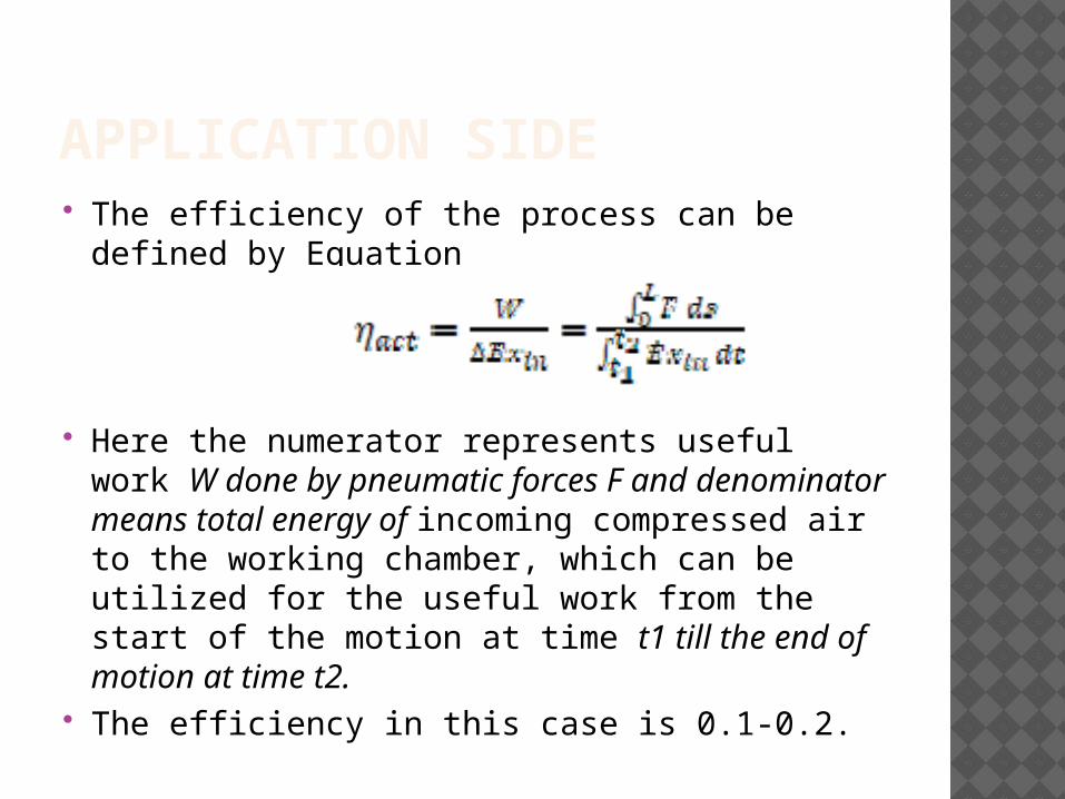
APPLICATION SIDE The efficiency of the process can be defined by
Equation
Here the numerator represents useful work W done by pneumatic forces F and denominator means total energy of incoming compressed air to the working chamber, which can be utilized for the useful work from the start of the motion at time t1 till the end of motion at time t2.
The efficiency in this case is 0.1-0.2.
OUTCOME OF ANALYSIS Dryers and pressure regulators have
efficiencies in an acceptable range The efficiency of compressor though not
very good is considerable Efficiency of applications of compressed
air is very poor Although the efficiency of the actuation
can vary depending on the situation under investigation, any results will make the total efficiency of the CAS (product of particular efficiencies) tend towards zero.

OUTCOME OF ANALYSIS As a considerable part of electric energy
is transferred into pressure energy of the medium and this high pressure energy is not utilized at the application side, compressed air usage leads to the most of the energy being wasted.
The application of the exergy analysis has shown that the critical point of the compressed air system is the application side, which is a limiting factor of the efficiency of the whole compressed air system.

SOLUTION FOR ENERGY
CONSERVATION IN VARIOUS
APPLICATIONS OF COMPRESSED AIR

AIM Future optimization of the compressed air
system should be focused on the application side, where a high potential of energy savings is projected.
In order to quantify air consumption of the CAS, different types of pneumatic actuators are modeled and the overall air consumption is compared to the real data available.
The process includes collection of available information such as pressure level of the particular end application, geometric parameters, working time/cycling, shift patterns etc. which is necessary for a mathematical model.

DETAILED STUDY OF COMPRESSED AIR APPLICATIONS There is a multi-purpose usage of compressed air
in the company The breakdown of air usage is:
fluidizing (conveying/cleaning – at two different pressure levels) - 67.12%
open blow applications (e.g. bowl feeding, index sensor blow-off) - 12.76%
filter pulsing - 5.92% actuation - 3.82% controllers sealing - 3.5% hoisting - 3.46% air whip cleaning - 1.77% PLC sealing 1.53% air gun 0.12%.

SOLUTION Based on the available information company has
applied leak elimination technique and pressure decay measurement
The difference between the model and measured values was initially almost 30%.
However, based on the leak estimation technique described below, the difference has been reduced to 6.7%, as summarized in Table below

SOLUTION The company also implements a
pressure decay measurement, which can be related to the leakage effect.
At end of a production period, all machines are stopped and the system is pressurized up to a pressure of 6.6 bar.
The estimate of leak flow rate is directly proportional to Volume, and so has a sensitivity of 1, thus, there is a potential for improvement of the technique by detailed volume estimation.

SOLUTION Based on the model, almost 80% of the
fluidizing air is used at pressure slightly higher than atmospheric and this air has been generated with considerably higher pressure level than actually required, thus a more detailed study of the process and possible local blower implementation could result in a substantial energy saving opportunity.

CONCLUSION The compressed air systems are complex and
any simplified approach will naturally lead to the differences between reality and the model.
However, it has been shown that it is possible to understand system behavior based on a suitable mathematical tool.
The investigation revealed poor compressed air energy utilization on the application side resulting in low overall system efficiency and several energy savings opportunities are suggested for specific applications found in the investigated companies.