Energy Automation SICAM P850 Power Monitoring Device SICAM ...DE_Edition_2)_CHAP_XX... · Products...
24
Answers for infrastructure and cities. Energy Automation SICAM P850 Power Monitoring Device SICAM P855 Power Monitoring Device and Power Quality Recorder
Transcript of Energy Automation SICAM P850 Power Monitoring Device SICAM ...DE_Edition_2)_CHAP_XX... · Products...
Answers for infrastructure and cities.
Energy Automation
SICAM P850 Power Monitoring DeviceSICAM P855 Power Monitoring Device and Power Quality Recorder
1/2 Power Quality and Measurements Product Catalog · Siemens SR 10 · Edition 2
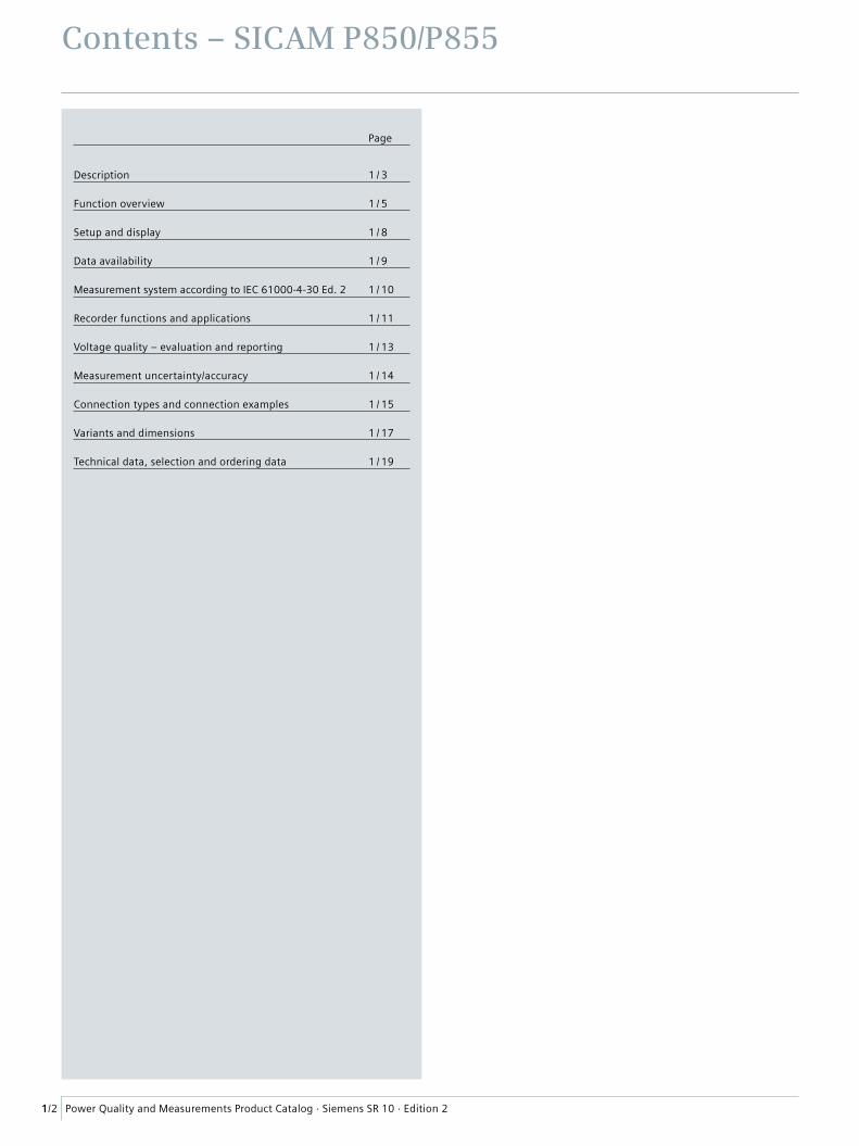
Contents – SICAM P850/P855
Page
Description 1 / 3
Function overview 1 / 5
Setup and display 1 / 8
Data availability 1 / 9
Measurement system according to IEC 61000-4-30 Ed. 2 1 / 10
Recorder functions and applications 1 / 11
Voltage quality – evaluation and reporting 1 / 13
Measurement uncertainty/accuracy 1 / 14
Connection types and connection examples 1 / 15
Variants and dimensions 1 / 17
Technical data, selection and ordering data 1 / 19
1/3Power Quality and Measurements Product Catalog · Siemens SR 10 · Edition 2
Description
Products – SICAM P850 / P855
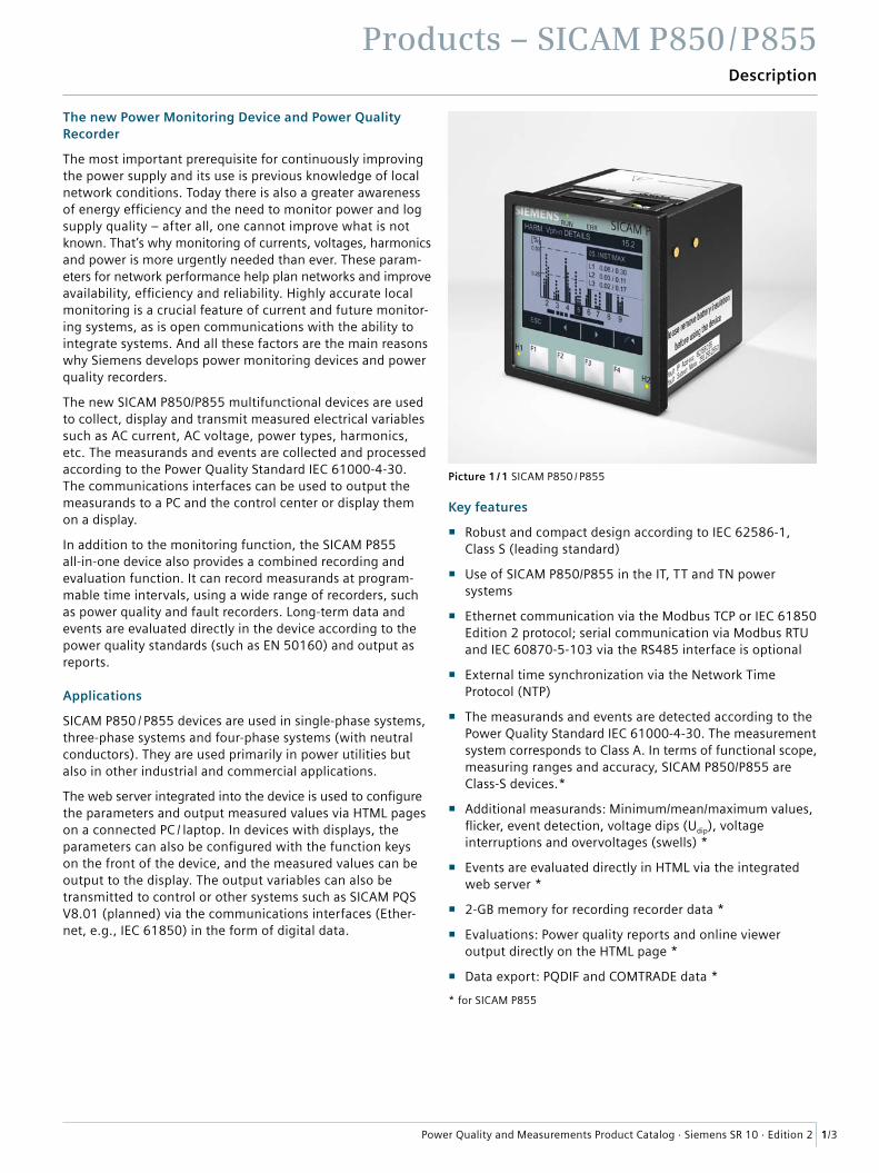
The new Power Monitoring Device and Power Quality Recorder
The most important prerequisite for continuously improving the power supply and its use is previous knowledge of local network conditions. Today there is also a greater awareness of energy efficiency and the need to monitor power and log supply quality – after all, one cannot improve what is not known. That’s why monitoring of currents, voltages, harmonics and power is more urgently needed than ever. These param-eters for network performance help plan networks and improve availability, efficiency and reliability. Highly accurate local monitoring is a crucial feature of current and future monitor-ing systems, as is open communications with the ability to integrate systems. And all these factors are the main reasons why Siemens develops power monitoring devices and power quality recorders.
The new SICAM P850/P855 multifunctional devices are used to collect, display and transmit measured electrical variables such as AC current, AC voltage, power types, harmonics, etc. The measurands and events are collected and processed according to the Power Quality Standard IEC 61000-4-30. The communications interfaces can be used to output the measurands to a PC and the control center or display them on a display.
In addition to the monitoring function, the SICAM P855 all-in-one device also provides a combined recording and evaluation function. It can record measurands at program-mable time intervals, using a wide range of recorders, such as power quality and fault recorders. Long-term data and events are evaluated directly in the device according to the power quality standards (such as EN 50160) and output as reports.
Applications
SICAM P850 / P855 devices are used in single-phase systems, three-phase systems and four-phase systems (with neutral conductors). They are used primarily in power utilities but also in other industrial and commercial applications.
The web server integrated into the device is used to configure the parameters and output measured values via HTML pages on a connected PC / laptop. In devices with displays, the parameters can also be configured with the function keys on the front of the device, and the measured values can be output to the display. The output variables can also be transmitted to control or other systems such as SICAM PQS V8.01 (planned) via the communications interfaces (Ether-net, e.g., IEC 61850) in the form of digital data.
Key features
� Robust and compact design according to IEC 62586-1, Class S (leading standard)
� Use of SICAM P850/P855 in the IT, TT and TN power systems
� Ethernet communication via the Modbus TCP or IEC 61850 Edition 2 protocol; serial communication via Modbus RTU and IEC 60870-5-103 via the RS485 interface is optional
� External time synchronization via the Network Time Protocol (NTP)
� The measurands and events are detected according to the Power Quality Standard IEC 61000-4-30. The measurement system corresponds to Class A. In terms of functional scope, measuring ranges and accuracy, SICAM P850/P855 are Class-S devices.*
� Additional measurands: Minimum/mean/maximum values, flicker, event detection, voltage dips (Udip), voltage interruptions and overvoltages (swells) *
� Events are evaluated directly in HTML via the integrated web server *
� 2-GB memory for recording recorder data *
� Evaluations: Power quality reports and online viewer output directly on the HTML page *
� Data export: PQDIF and COMTRADE data *
* for SICAM P855
Picture 1 / 1 SICAM P850 / P855
Products – SICAM P850 / P855
1/4 Power Quality and Measurements Product Catalog · Siemens SR 10 · Edition 2
Description
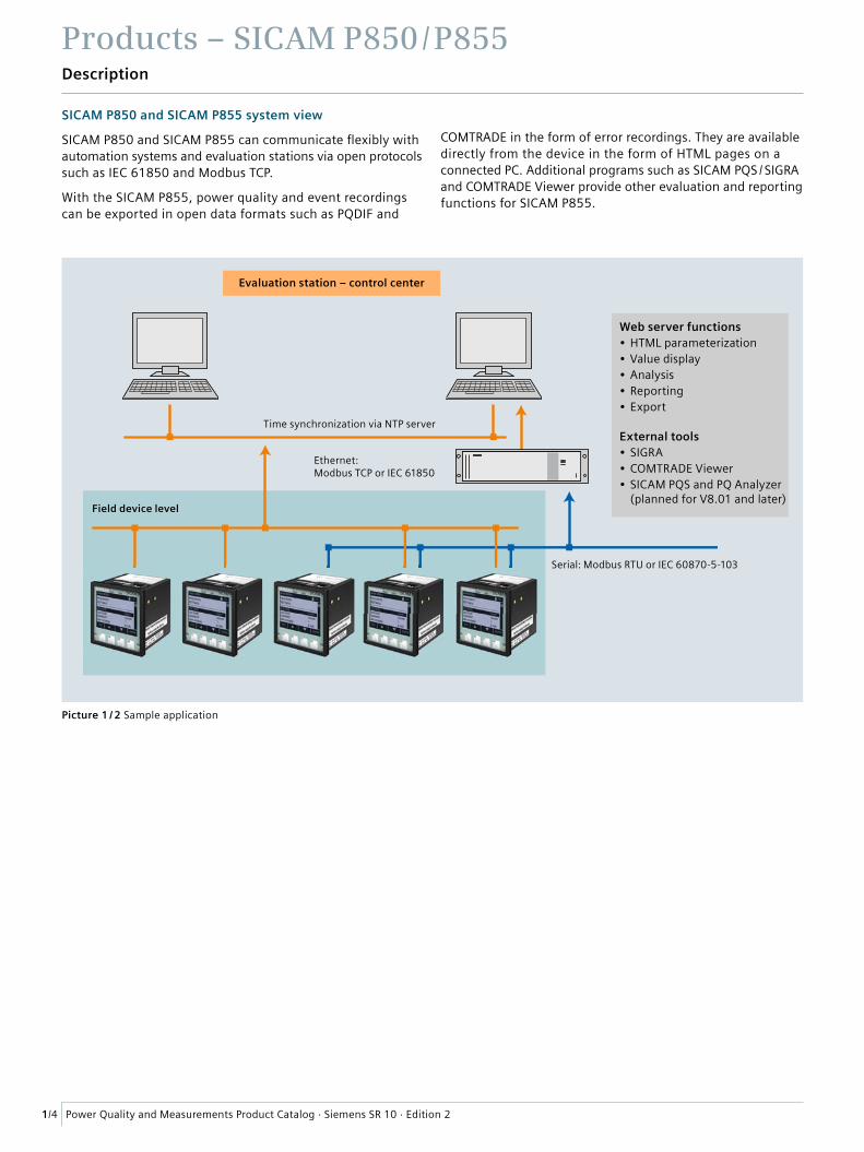
SICAM P850 and SICAM P855 system view
SICAM P850 and SICAM P855 can communicate flexibly with automation systems and evaluation stations via open protocols such as IEC 61850 and Modbus TCP.
With the SICAM P855, power quality and event recordings can be exported in open data formats such as PQDIF and
COMTRADE in the form of error recordings. They are available directly from the device in the form of HTML pages on a connected PC. Additional programs such as SICAM PQS / SIGRA and COMTRADE Viewer provide other evaluation and reporting functions for SICAM P855.
Picture 1 / 2 Sample application
Serial: Modbus RTU or IEC 60870-5-103
Ethernet: Modbus TCP or IEC 61850
Time synchronization via NTP server
Field device level
Evaluation station – control center
Web server functions• HTML parameterization• Value display• Analysis• Reporting• Export
External tools• SIGRA• COMTRADE Viewer• SICAM PQS and PQ Analyzer (planned for V8.01 and later)
1/5Power Quality and Measurements Product Catalog · Siemens SR 10 · Edition 2
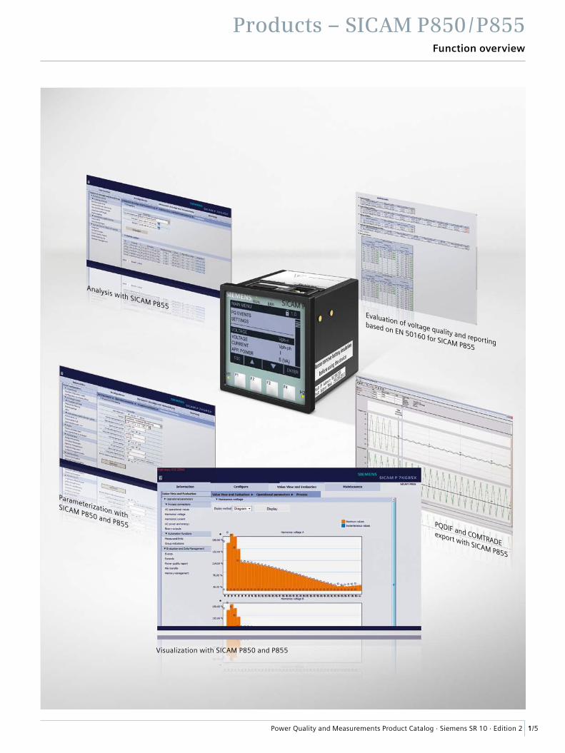
Products – SICAM P850 / P855Function overview
Analysis with SICAM P855Evaluation of voltage quality and reporting
based on EN 50160 for SICAM P855
Visualization with SICAM P850 and P855
Parameterization with SICAM P850 and P855 PQDIF and COMTRADE
export with SICAM P855
Products – SICAM P850 / P855Function overview
1/6 Power Quality and Measurements Product Catalog · Siemens SR 10 · Edition 2
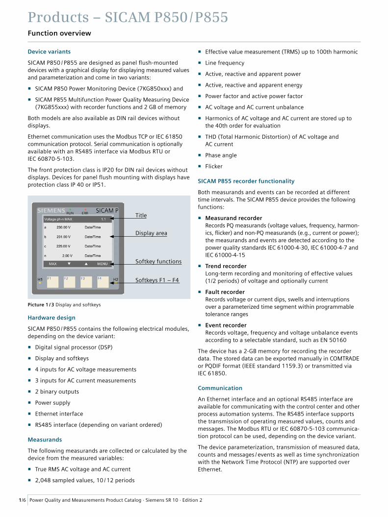
Device variants
SICAM P850 / P855 are designed as panel flush-mounted devices with a graphical display for displaying measured values and parameterization and come in two variants:
� SICAM P850 Power Monitoring Device (7KG850xxx) and
� SICAM P855 Multifunction Power Quality Measuring Device (7KG855xxx) with recorder functions and 2 GB of memory
Both models are also available as DIN rail devices without displays.
Ethernet communication uses the Modbus TCP or IEC 61850 communication protocol. Serial communication is optionally available with an RS485 interface via Modbus RTU or IEC 60870-5-103.
The front protection class is IP20 for DIN rail devices without displays. Devices for panel flush mounting with displays have protection class IP 40 or IP51.
Hardware design
SICAM P850 / P855 contains the following electrical modules, depending on the device variant:
� Digital signal processor (DSP)
� Display and softkeys
� 4 inputs for AC voltage measurements
� 3 inputs for AC current measurements
� 2 binary outputs
� Power supply
� Ethernet interface
� RS485 interface (depending on variant ordered)
Measurands
The following measurands are collected or calculated by the device from the measured variables:
� True RMS AC voltage and AC current
� 2,048 sampled values, 10 / 12 periods
� Effective value measurement (TRMS) up to 100th harmonic
� Line frequency
� Active, reactive and apparent power
� Active, reactive and apparent energy
� Power factor and active power factor
� AC voltage and AC current unbalance
� Harmonics of AC voltage and AC current are stored up to the 40th order for evaluation
� THD (Total Harmonic Distortion) of AC voltage and AC current
� Phase angle
� Flicker
SICAM P855 recorder functionality
Both measurands and events can be recorded at different time intervals. The SICAM P855 device provides the following functions:
� Measurand recorder Records PQ measurands (voltage values, frequency, harmon-ics, flicker) and non-PQ measurands (e.g., current or power); the measurands and events are detected according to the power quality standards IEC 61000-4-30, IEC 61000-4-7 and IEC 61000-4-15
� Trend recorder Long-term recording and monitoring of effective values (1/2 periods) of voltage and optionally current
� Fault recorder Records voltage or current dips, swells and interruptions over a parameterized time segment within programmable tolerance ranges
� Event recorder Records voltage, frequency and voltage unbalance events according to a selectable standard, such as EN 50160
The device has a 2-GB memory for recording the recorder data. The stored data can be exported manually in COMTRADE or PQDIF format (IEEE standard 1159.3) or transmitted via IEC 61850.
Communication
An Ethernet interface and an optional RS485 interface are available for communicating with the control center and other process automation systems. The RS485 interface supports the transmission of operating measured values, counts and messages. The Modbus RTU or IEC 60870-5-103 communica-tion protocol can be used, depending on the device variant.
The device parameterization, transmission of measured data, counts and messages / events as well as time synchronization with the Network Time Protocol (NTP) are supported over Ethernet.
Title
Softkey functions
Softkeys F1 – F4
Display area
Picture 1 / 3 Display and softkeys
Products – SICAM P850 / P855Function overview
1/7Power Quality and Measurements Product Catalog · Siemens SR 10 · Edition 2
The SICAM P850 and P855 devices support the transmission of operating measured values with the two Ethernet protocol options – via both Modbus TCP and IEC 61850.
With SICAM P855, it is also possible to transmit voltage events via Modbus TCP. The power quality data can also be exported via IEC 61850 (as standard PQDIF/COMTRADE data).
Time synchronization
The devices need to have the date and time during operation for all time-relevant processes. SICAM P850 / P855 therefore uses time synchronization while communicating with periph-eral devices to guarantee a common time basis and to permit time stamping of the process data. The following types of time synchronization can be carried out:
� Time synchronization via Ethernet NTP (preferred) SICAM P850/P855 has an SNTP client (Simple Network Time Protocol) that can be connected to two NTP servers (Network Time Protocol) for external time synchronization: the primary and secondary (redundant) NTP servers.
� External time synchronization via the field bus using the Modbus RTU or IEC 60870-5-103 communication protocol
� Real Time Clock (RTC) If external time synchronization is not possible, data can be synchronized with the time pulse of an internal clock.
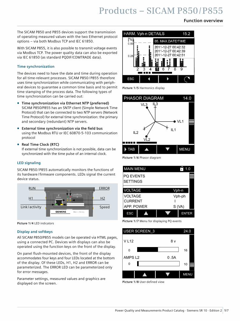
LED signaling
SICAM P850 / P855 automatically monitors the functions of its hardware / firmware components. LEDs signal the current device status.
Display and softkeys
All SICAM P850/P855 models can be operated via HTML pages, using a connected PC. Devices with displays can also be operated using the function keys on the front of the display.
On panel flush-mounted devices, the front of the display accommodates four keys and four LEDs located at the bottom of the display. Of these LEDs, H1, H2 and ERROR can be parameterized. The ERROR LED can be parameterized only for error messages.
Parameter settings, measured values and graphics are displayed on the screen. Picture 1 / 8 User-defined view
AMPS L2 0 .5A
V L12 8 v
MENU
USER SCREEN_3 24.0
0 16
0 10
Picture 1 / 5 Harmonics display
TAB MENU
PHASOR DIAGRAM 14.0
VL1
VL2
VL3
IL1IL2
IL3
Picture 1 / 6 Phasor diagram
ESC ENTER
VOLTAGE Vph-ph
SETTINGS
VOLTAGE Vph-n
MAIN MENU 1.0
PQ EVENTS
CURRENT IAPP. POWER S (VA)
Picture 1 / 7 Menu for displaying PQ events
RUN
Link / activity
H2
Speed
ERROR
H1
Picture 1 / 4 LED indicators
Products – SICAM P850 / P855Setup and display
1/8 Power Quality and Measurements Product Catalog · Siemens SR 10 · Edition 2
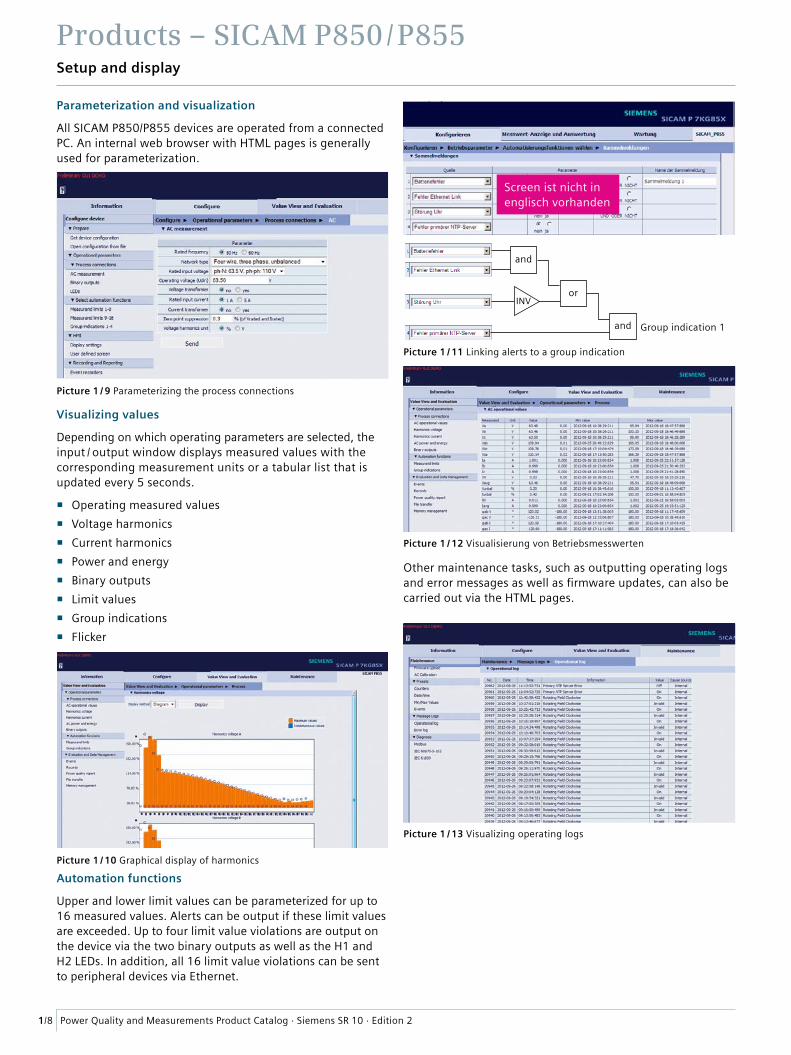
Parameterization and visualization
All SICAM P850/P855 devices are operated from a connected PC. An internal web browser with HTML pages is generally used for parameterization.
Visualizing values
Depending on which operating parameters are selected, the input / output window displays measured values with the corresponding measurement units or a tabular list that is updated every 5 seconds.
� Operating measured values
� Voltage harmonics
� Current harmonics
� Power and energy
� Binary outputs
� Limit values
� Group indications
� Flicker
Automation functions
Upper and lower limit values can be parameterized for up to 16 measured values. Alerts can be output if these limit values are exceeded. Up to four limit value violations are output on the device via the two binary outputs as well as the H1 and H2 LEDs. In addition, all 16 limit value violations can be sent to peripheral devices via Ethernet.
Other maintenance tasks, such as outputting operating logs and error messages as well as firmware updates, can also be carried out via the HTML pages.
Picture 1 / 9 Parameterizing the process connections
Picture 1 / 10 Graphical display of harmonics
Group indication 1
and
and
orINV
Picture 1 / 11 Linking alerts to a group indication
Picture 1 / 12 Visualisierung von Betriebsmesswerten
Picture 1 / 13 Visualizing operating logs
Screen ist nicht in englisch vorhanden
Products – SICAM P850 / P855
1/9Power Quality and Measurements Product Catalog · Siemens SR 10 · Edition 2
Data availability
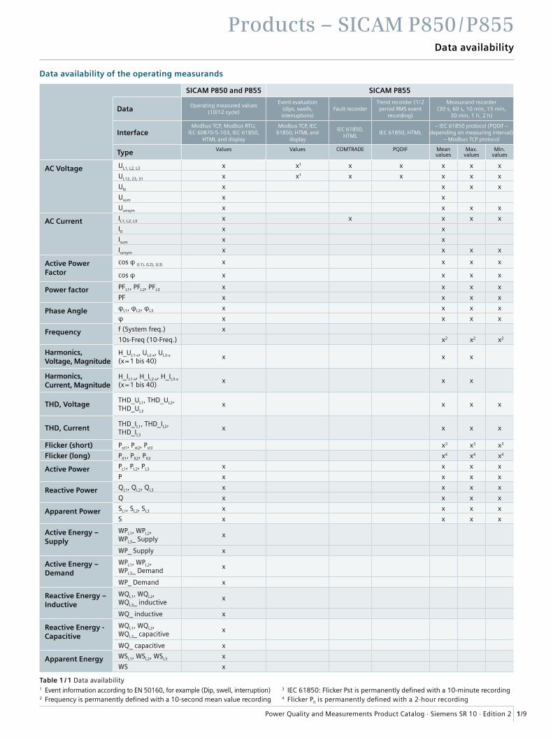
Data availability of the operating measurands
Table 1 / 1 Data availability
SICAM P850 and P855 SICAM P855
Data Operating measured values (10/12 cycle)
Event evaluation(dips, swells, interruptions)
Fault recorderTrend recorder (1/ 2 period RMS event
recording)
Measurand recorder(30 s, 60 s, 10 min, 15 min,
30 min, 1 h, 2 h)
InterfaceModbus TCP, Modbus RTU,
IEC 60870-5-103, IEC 61850,HTML and display
Modbus TCP, IEC 61850, HTML and
display
IEC 61850, HTML
IEC 61850, HTML– IEC 61850 protocol (PQDif –
depending on measuring interval)– Modbus TCP protocol
Type Values Values COMTRADE PQDIF Mean values
Max. values
Min. values
AC Voltage UL1, L2, L3 x x1 x x x x x
UL12, 23, 31 x x1 x x x x x
UN x x x x
Usum x x
Uunsym x x x x
AC Current IL1, L2, L3 x x x x x
I0 x x
Isum x x
Iunsym x x x x
Active Power Factor
cos φ (L1), (L2), (L3) x x x x
cos φ x x x x
Power factor PFL1, PFL2, PFL3 x x x x
PF x x x x
Phase Angle φL1, φL2, φL3 x x x x
φ x x x x
Frequency f (System freq.) x
10s-Freq (10-Freq.) x2 x2 x2
Harmonics, Voltage, Magnitude
H_UL1-x, UL2-x, UL3-x
(x = 1 bis 40)x x x
Harmonics, Current, Magnitude
H_IL1-x, H_IL2-x, H_IL3-x
(x = 1 bis 40)x x x
THD, Voltage THD_UL1, THD_UL2, THD_UL3
x x x x
THD, Current THD_IL1, THD_IL2, THD_IL3
x x x x
Flicker (short) Pst1, Pst2, Pst3 x3 x3 x3
Flicker (long) Plt1, Plt2, Plt3 x4 x4 x4
Active Power PL1, PL2, PL3 x x x x
P x x x x
Reactive Power QL1, QL2, QL3 x x x x
Q x x x x
Apparent Power SL1, SL2, SL3 x x x x
S x x x x
Active Energy – Supply
WPL1, WPL2, WPL3_ Supply
x
WP_ Supply x
Active Energy – Demand
WPL1, WPL2, WPL3_ Demand
x
WP_ Demand x
Reactive Energy – Inductive
WQL1, WQL2, WQL3_ inductive
x
WQ_ inductive x
Reactive Energy - Capacitive
WQL1, WQL2, WQL3_ capacitive
x
WQ_ capacitive x
Apparent Energy WSL1, WSL2, WSL3 x
WS x
1 Event information according to EN 50160, for example (Dip, swell, interruption)2 Frequency is permanently defined with a 10-second mean value recording
3 IEC 61850: Flicker Pst is permanently defined with a 10-minute recording 4 Flicker Plt is permanently defined with a 2-hour recording
1/10 Power Quality and Measurements Product Catalog · Siemens SR 10 · Edition 2
Products – SICAM P855Measurement system according to IEC 61000-4-30 Ed. 2
Functions of the measurement system
SICAM P850 / P855 are devices for measuring voltage quality according to IEC 61000-4-30 Ed. 2 and other measurands in single-phase or multi-phase supply systems. The measure-ment system is implemented according to Class A. In terms of functional scope, measuring ranges and accuracy, SICAM P850 / P855 devices are Class-S measuring devices.
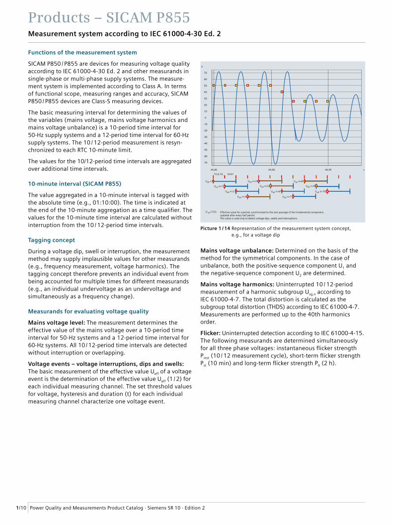
The basic measuring interval for determining the values of the variables (mains voltage, mains voltage harmonics and mains voltage unbalance) is a 10-period time interval for 50-Hz supply systems and a 12-period time interval for 60-Hz supply systems. The 10 / 12-period measurement is resyn-chronized to each RTC 10-minute limit.
The values for the 10/12-period time intervals are aggregated over additional time intervals.
10-minute interval (SICAM P855)
The value aggregated in a 10-minute interval is tagged with the absolute time (e.g., 01:10:00). The time is indicated at the end of the 10-minute aggregation as a time qualifier. The values for the 10-minute time interval are calculated without interruption from the 10 / 12-period time intervals.
Tagging concept
During a voltage dip, swell or interruption, the measurement method may supply implausible values for other measurands (e.g., frequency measurement, voltage harmonics). The tagging concept therefore prevents an individual event from being accounted for multiple times for different measurands (e.g., an individual undervoltage as an undervoltage and simultaneously as a frequency change).
Measurands for evaluating voltage quality
Mains voltage level: The measurement determines the effective value of the mains voltage over a 10-period time interval for 50-Hz systems and a 12-period time interval for 60-Hz systems. All 10 / 12-period time intervals are detected without interruption or overlapping.
Voltage events – voltage interruptions, dips and swells: The basic measurement of the effective value Ueff of a voltage event is the determination of the effective value Ueff (1 / 2) for each individual measuring channel. The set threshold values for voltage, hysteresis and duration (t) for each individual measuring channel characterize one voltage event.
Mains voltage unbalance: Determined on the basis of the method for the symmetrical components. In the case of unbalance, both the positive-sequence component U1 and the negative-sequence component U2 are determined.
Mains voltage harmonics: Uninterrupted 10 / 12-period measurement of a harmonic subgroup Usg,n according to IEC 61000-4-7. The total distortion is calculated as the subgroup total distortion (THDS) according to IEC 61000-4-7. Measurements are performed up to the 40th harmonics order.
Flicker: Uninterrupted detection according to IEC 61000-4-15. The following measurands are determined simultaneously for all three phase voltages: instantaneous flicker strength Pinst (10 / 12 measurement cycle), short-term flicker strength Pst (10 min) and long-term flicker strength Plt (2 h).
Effective value for a period, synchronized to the zero passage of the fundamental component, updated after every half period.This value is used only to detect voltage dips, swells and interruptions
70
60
50
40
30
20
10
0
-10
-20
-30
-40
-50
-60
-70
44,85
15.6.10, 16:47
U eff (1/2):
Uoff n
Uoff n+1
Uoff n+2
Uoff n+3
Uoff n+4
Uoff n+5
Uoff n+6
Uoff n+7
Uoff n+8
Uoff n+9
Uoff n+10
44,90 44,95
V
s
Picture 1 / 14 Representation of the measurement system concept, e.g., for a voltage dip
1/11Power Quality and Measurements Product Catalog · Siemens SR 10 · Edition 2
Products – SICAM P855Recorder functions and applications
SICAM P855: Recording measured values and events
SICAM P855 provides a variety of recording options for monitoring and analyzing voltage quality.
Measurand recorder
The measurand recorder records not only measured values for determining the power quality but also various other meas-ured values (e.g., minimum / maximum values). The recording of the following measurands can be parameterized in the user interface:
� PQ measurands for determining power quality: – Averaging intervals for frequency (permanently set to 10 s) – Averaging intervals for voltage, voltage unbalance and harmonics (30 s, 60 s, 10 min, 15 min, 30 min, 1 h, 2 h) – Flicker: Short-term flicker strength Pst (10 min) and
long-term flicker strength Plt (2 h)
� Additional data: Current, current unbalance, active power, apparent power, reactive power, THD of voltage, THD of current, power factor, active power factor, phase angle, energy values
� Recording of minimum values (mean values)
� Recording of maximum values (mean values)
The measuring interval can be set in various increments from 30 seconds to 2 hours. The interval for measuring frequency is permanently set to 10 seconds.
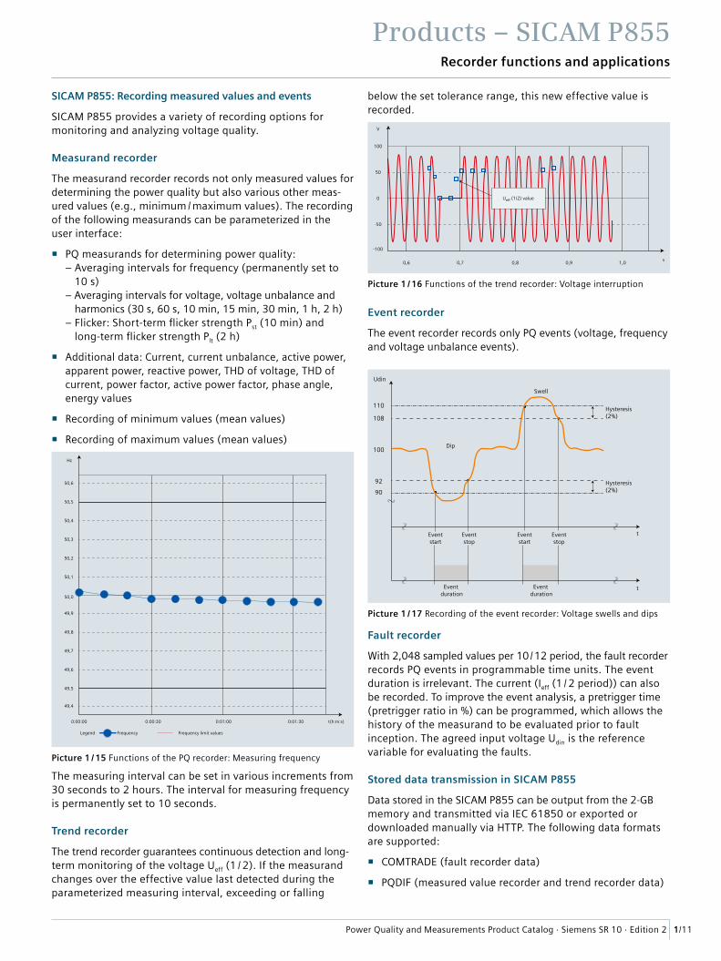
Trend recorder
The trend recorder guarantees continuous detection and long- term monitoring of the voltage Ueff (1 / 2). If the measurand changes over the effective value last detected during the parameterized measuring interval, exceeding or falling
below the set tolerance range, this new effective value is recorded.
Event recorder
The event recorder records only PQ events (voltage, frequency and voltage unbalance events).
Fault recorder
With 2,048 sampled values per 10 / 12 period, the fault recorder records PQ events in programmable time units. The event duration is irrelevant. The current (Ieff (1 / 2 period)) can also be recorded. To improve the event analysis, a pretrigger time (pretrigger ratio in %) can be programmed, which allows the history of the measurand to be evaluated prior to fault inception. The agreed input voltage Udin is the reference variable for evaluating the faults.
Stored data transmission in SICAM P855
Data stored in the SICAM P855 can be output from the 2-GB memory and transmitted via IEC 61850 or exported or downloaded manually via HTTP. The following data formats are supported:
� COMTRADE (fault recorder data)
� PQDIF (measured value recorder and trend recorder data)
Swell
Dip
Eventstart
Eventstop
Eventstart
Eventstop
Event duration
Event duration
Hysteresis(2%)
Hysteresis(2%)
t
Udin
t
110
108
100
92
90
100
50
0
-50
-100
0,6 0,7 0,8 0,9 1,0
V
s
Ueff (1/2) value
Picture 1 / 16 Functions of the trend recorder: Voltage interruption
Picture 1 / 17 Recording of the event recorder: Voltage swells and dips
0:00:00
Legend Frequency Frequency limit values
0:00:30 0:01:00 0:01:30 t(h:m:s)
50,6
50,5
50,4
50,3
50,2
50,1
50,0
49,9
49,8
49,7
49,6
49,5
49,4
Hz
Picture 1 / 15 Functions of the PQ recorder: Measuring frequency
1/12 Power Quality and Measurements Product Catalog · Siemens SR 10 · Edition 2
Products – SICAM P855Recorder functions and applications
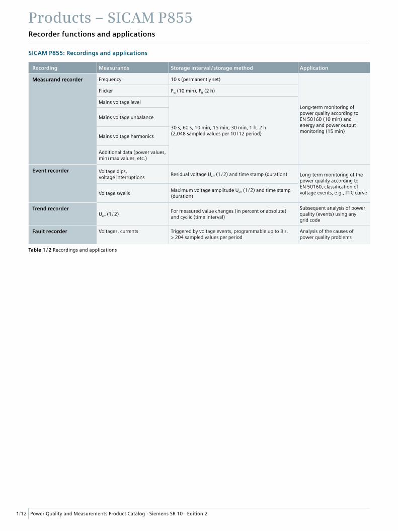
SICAM P855: Recordings and applications
Table 1 / 2 Recordings and applications
Recording Measurands Storage interval / storage method Application
Measurand recorder Frequency 10 s (permanently set)
Long-term monitoring of power quality according to EN 50160 (10 min) and energy and power output monitoring (15 min)
Flicker Pst (10 min), Plt (2 h)
Mains voltage level
30 s, 60 s, 10 min, 15 min, 30 min, 1 h, 2 h (2,048 sampled values per 10 / 12 period)
Mains voltage unbalance
Mains voltage harmonics
Additional data (power values, min / max values, etc.)
Event recorder Voltage dips, voltage interruptions
Residual voltage Ueff (1 / 2) and time stamp (duration) Long-term monitoring of the power quality according to EN 50160, classification of voltage events, e.g., ITIC curveVoltage swells
Maximum voltage amplitude Ueff (1 / 2) and time stamp (duration)
Trend recorderUeff (1 / 2)
For measured value changes (in percent or absolute) and cyclic (time interval)
Subsequent analysis of power quality (events) using any grid code
Fault recorder Voltages, currents Triggered by voltage events, programmable up to 3 s, > 204 sampled values per period
Analysis of the causes of power quality problems
Products – SICAM P855Voltage quality – evaluation and reporting
1/13Power Quality and Measurements Product Catalog · Siemens SR 10 · Edition 2
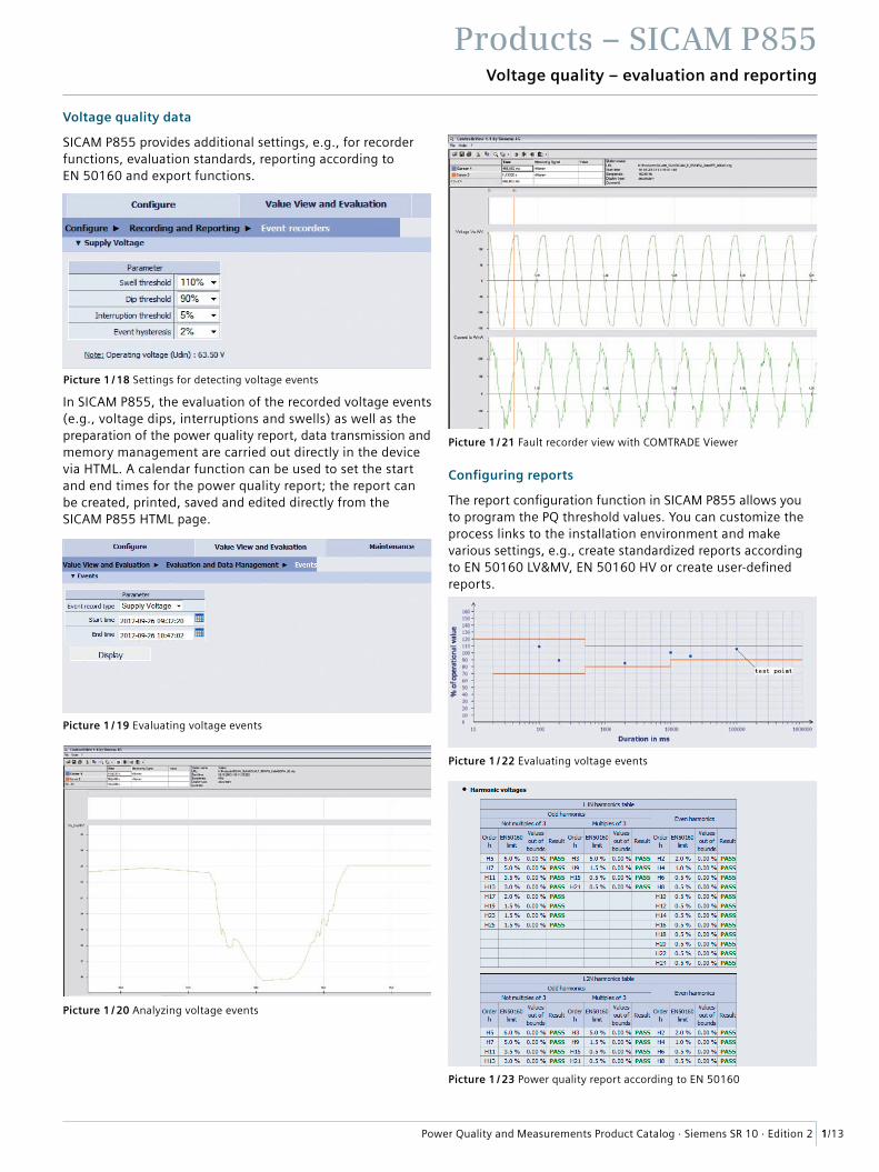
Voltage quality data
SICAM P855 provides additional settings, e.g., for recorder functions, evaluation standards, reporting according to EN 50160 and export functions.
In SICAM P855, the evaluation of the recorded voltage events (e.g., voltage dips, interruptions and swells) as well as the preparation of the power quality report, data transmission and memory management are carried out directly in the device via HTML. A calendar function can be used to set the start and end times for the power quality report; the report can be created, printed, saved and edited directly from the SICAM P855 HTML page.
Configuring reports
The report configuration function in SICAM P855 allows you to program the PQ threshold values. You can customize the process links to the installation environment and make various settings, e.g., create standardized reports according to EN 50160 LV&MV, EN 50160 HV or create user-defined reports.
Picture 1 / 18 Settings for detecting voltage events
Picture 1 / 19 Evaluating voltage events
Picture 1 / 20 Analyzing voltage events
Picture 1 / 23 Power quality report according to EN 50160
Picture 1 / 22 Evaluating voltage events
Picture 1 / 21 Fault recorder view with COMTRADE Viewer
Products – SICAM P850 / P855
1/14 Power Quality and Measurements Product Catalog · Siemens SR 10 · Edition 2
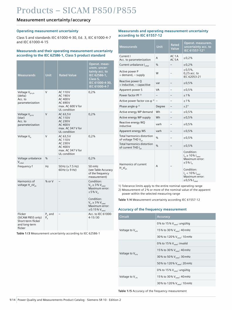
Measurement uncertainty / accuracy
Operating measurement uncertainty
Class S and standards IEC 61000-4-30, Ed. 3, IEC 61000-4-7 and IEC 61000-4-15
Measurands and their operating measurement uncertainty according to the IEC 62586-1, Class S product standard
Measurands and operating measurement uncertainty according to IEC 61557-12
Accuracy of the frequency measurement
1) Tolerance limits apply to the entire nominal operating range 2) Measurement of 2 % or more of the nominal value of the apparent
power within the selected measuring range
Table 1 / 4 Measurement uncertainty according IEC 61557-12
Measurands UnitRated Value
Operat. measurem.uncertainty acc. to IEC 61557-121)
Current IAcc. to parameterization
AAC 1 AAC 5 A
± 0,2 %
Current unbalance Iunbal % – ± 0,2 %
Active power P+ demand, – supply
W –± 0,5 %,0,2 S acc. to IEC 62053-21
Reactive power Q+ inductive, – capacitive
var – ± 0,5 %
Apparent power S VA – ± 0,5 %
Power factor PF 2) – – ± 1 %
Active power factor cos φ 2) – – ± 1 %
Phase angle φ 2) Degree – ± 2 °
Active energy WP demand Wh – ± 0,5 %
Active energy WP supply Wh – ± 0,5 %
Reactive energy WQ inductive
varh – ± 0,5 %
Apparent energy WS varh – ± 0,5 %
Total harmonics distortion of voltage THD Vph
% – ± 0,5 %
Total harmonics distortion of current THD Iph
% – ± 0,5 %
Harmonics of current H_xIph
A –
Condition:Im ≥ 10 % Irated
Maximum error:± 5 % Im
Condition:Im < 10 % Irated
Maximum error:± 0,5 % Irated
Circuit Accuracy
Voltage to Va-N
0 % to 15 % Vrated: ungültig
15 % to 30 % Vrated: 40 mHz
30 % to 120 % Vrated: 10 mHz
Voltage to Vb-N
0 % to 15 % Vrated: invalid
15 % to 30 % Vrated: 40 mHz
30 % to 50 % Vrated: 30 mHz
50 % to 120 % Vrated: 20 mHz
Voltage to Vc-N
0 % to 15 % Vrated: ungültig
15 % to 30 % Vrated: 40 mHz
30 % to 120 % Vrated: 10 mHz
Table 1 / 3 Measurement uncertainty according to IEC 62586-1
Table 1 / 5 Accuracy of the frequency measurement
Measurands Unit Rated Value
Operat. meas-urem. uncer-tainty acc. to IEC 62586-1, Class S, IEC 61000-4-30, IEC 61000-4-7
Voltage Vph-ph
(delta)Acc. to parameterization
V AC 110 VAC 190 VAC 400 VAC 690 Vmax. AC 600 V for UL condition
0,2 %
Voltage Vph-N
(star)Acc. to parameterization
V AC 63,5 VAC 110 VAC 230 VAC 400 Vmax. AC 347 V for UL condition
0,2 %
Voltage VN V AC 63,5 VAC 110 VAC 230 VAC 400 Vmax. AC 347 V for UL condition
0,2 %
Voltage unbalance Vunbal
% – 0,2 %
Frequency f Hz 50 Hz (± 7.5 Hz)60 Hz (± 9 Hz)
50 mHz(see Table Accuracy of the frequency measurement)
Harmonics of voltage H_xVph
% or V – Condition:Vm ≥ 3 % Vrated
Maximum error:± 5 % Vm
Condition:Vm ≥ 3 % Vrated
Maximum error:± 0.15 % Vrated
Flicker (SICAM P855 only) Short-term flicker and long-term flicker
Pst and Plt
– Acc. to IEC 61000-4-15 / 30
Products – SICAM P850 / P855
1/15Power Quality and Measurements Product Catalog · Siemens SR 10 · Edition 2
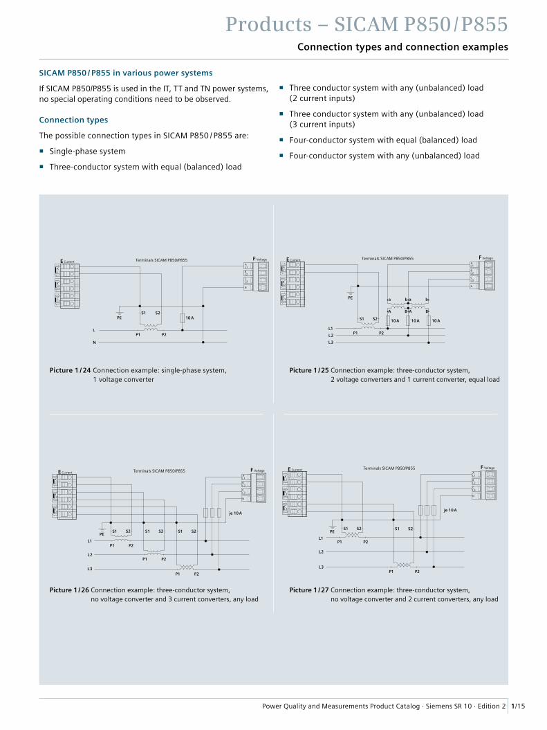
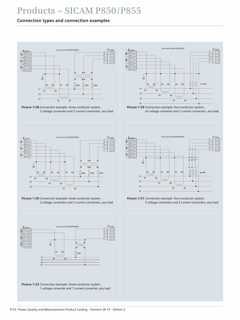
Connection types and connection examples
SICAM P850 / P855 in various power systems
If SICAM P850/P855 is used in the IT, TT and TN power systems, no special operating conditions need to be observed.
Connection types
The possible connection types in SICAM P850 / P855 are:
� Single-phase system
� Three-conductor system with equal (balanced) load
� Three conductor system with any (unbalanced) load (2 current inputs)
� Three conductor system with any (unbalanced) load (3 current inputs)
� Four-conductor system with equal (balanced) load
� Four-conductor system with any (unbalanced) load
Terminals SICAM P850/P855
N
F Voltage
AL 1
BL 2
CL 3
S1 S2PE
L
N
P1 P2
AL 1
E Current
BL 2
CL 3
10 A
Picture 1 / 24 Connection example: single-phase system, 1 voltage converter
Terminals SICAM P850/P855
N
F Voltage
AL 1
BL 2
CL 3
S1 S2
L1
L2
L3
AL 1
E Current
BL 2
CL 3
PE
je 10 A
S1 S2
P1 P2
P1 P2
Picture 1 / 27 Connection example: three-conductor system, no voltage converter and 2 current converters, any load
AL 1
E Current Terminals SICAM P850/P855
BL 2
CL 3
N
F Voltage
AL 1
BL 2
CL 3
S1 S2
L1P1 P2L2
L3
A AB B
a ab bPE
10 A 10 A 10 A
Picture 1 / 25 Connection example: three-conductor system, 2 voltage converters and 1 current converter, equal load
Terminals SICAM P850/P855
N
F Voltage
AL 1
BL 2
CL 3
S1 S2
L1P1 P2
L2
L3
S1 S2 S1 S2
AL 1
E Current
BL 2
CL 3
PE
P1 P2
P1 P2
je 10 A
Picture 1 / 26 Connection example: three-conductor system, no voltage converter and 3 current converters, any load
Products – SICAM P850 / P855
1/16 Power Quality and Measurements Product Catalog · Siemens SR 10 · Edition 2
Connection types and connection examples
Picture 1 / 32 Connection example: three-conductor system, 1 voltage converter and 1 current converter, any load
AL 1
E Current
N
F VoltageTerminals SICAM P850/P855
BL 2
CL 3
AL 1
BL 2
CL 3
S1 S2
PE
L1
N
P1 P2L2L3
a b
A B
10 A
Picture 1 / 31 Connection example: four-conductor system, 3 voltage converters and 3 current converters, any load
Terminals SICAM P850/P855
AL 1
E Current
BL 2
CL 3
S1 S2
L1
L2
L3
P1 P2
P1 P2
S1 S2
PE
P1 P2
N
F Voltage
AL 1
BL 2
CL 3
S1 S2
N
a
b
A
B
a a
b b
B B
A A
je 10 A
Terminals SICAM P850/P855
N
F Voltage
AL 1
BL 2
CL 3
S1 S2
L1
L2
L3
AL 1
E Current
BL 2
CL 3
P1 P2
P1 P2
S1 S2
PE
a ab b
A AB B
10 A 10 A 10 A
Picture 1 / 28 Connection example: three-conductor system, 2 voltage converters and 2 current converters, any load
Terminals SICAM P850/P855
N
F Voltage
AL 1
BL 2
CL 3
a ab b
A AB B
AL 1
E Current
BL 2
CL 3
S1 S2
L1
L2
L3
P1 P2
P1 P2
S1 S2
PE
P1 P2
S1 S2 10 A 10 A 10 A
Picture 1 / 30 Connection example: three-conductor system, 2 voltage converters and 3 current converters, any load
Terminals SICAM P850/P855
AL 1
E Current
BL 2
CL 3
S1 S2
L1
L2
L3
P1 P2
P1 P2
S1 S2
PE
P1 P2
N
F Voltage
AL 1
BL 2
CL 3
S1 S2
N
je 10 A
Picture 1 / 29 Connection example: four-conductor system, no voltage converter and 3 current converters, any load
Products – SICAM P850 / P855
1/17Power Quality and Measurements Product Catalog · Siemens SR 10 · Edition 2
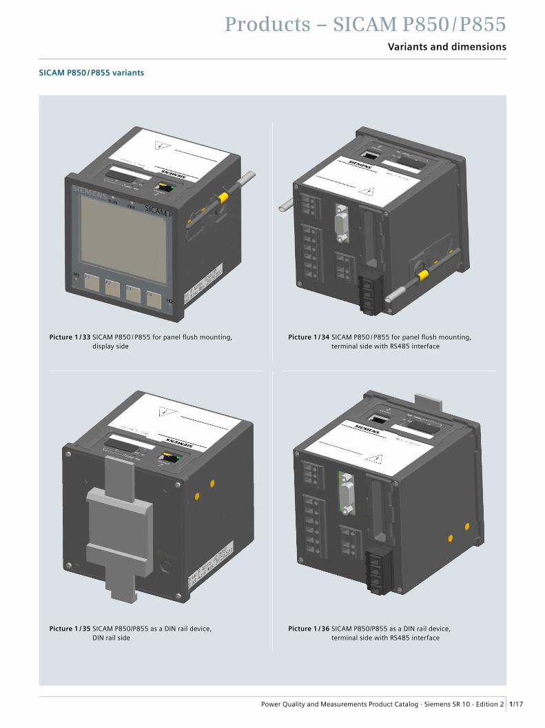
Variants and dimensions
SICAM P850 / P855 variants
Picture 1 / 33 SICAM P850 / P855 for panel flush mounting, display side
Picture 1 / 34 SICAM P850 / P855 for panel flush mounting, terminal side with RS485 interface
Picture 1 / 35 SICAM P850/P855 as a DIN rail device, DIN rail side
Picture 1 / 36 SICAM P850/P855 as a DIN rail device, terminal side with RS485 interface
Products – SICAM P850 / P855
1/18 Power Quality and Measurements Product Catalog · Siemens SR 10 · Edition 2
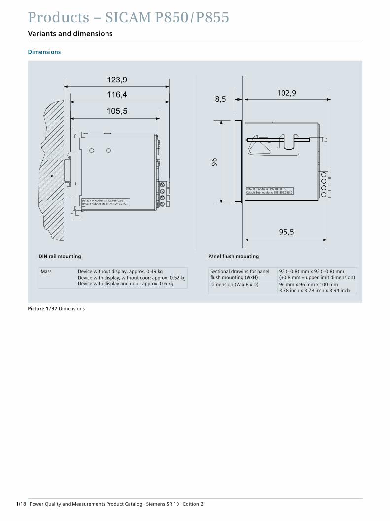
Variants and dimensions
Dimensions
123,9
116,4
105,5
Default IP Address: 192.168.0.55Default Subnet Mask: 255.255.255.0
Default P Address: 192188.0.55Default Subnet Mask: 255.255.255.0
102,9
95,5
8,5
96
Mass Device without display: approx. 0.49 kgDevice with display, without door: approx. 0.52 kgDevice with display and door: approx. 0.6 kg
Sectional drawing for panel flush mounting (WxH)
92 (+0.8) mm x 92 (+0.8) mm (+0.8 mm = upper limit dimension)
Dimension (W x H x D) 96 mm x 96 mm x 100 mm3.78 inch x 3.78 inch x 3.94 inch
Picture 1 / 37 Dimensions
DIN rail mounting Panel flush mounting
Products – SICAM P850 / P855
1/19Power Quality and Measurements Product Catalog · Siemens SR 10 · Edition 2
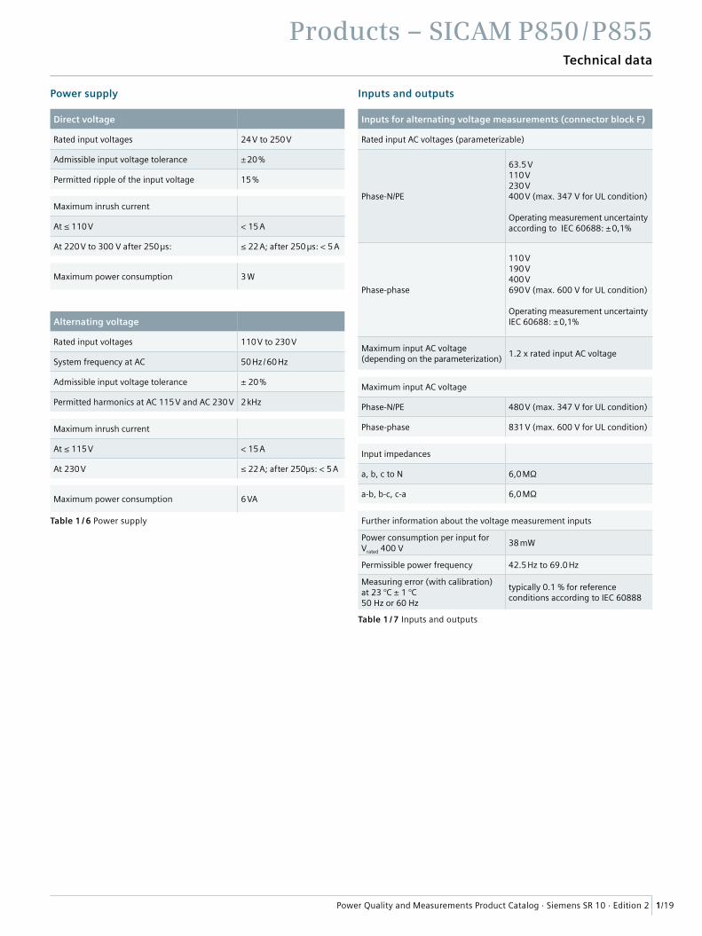
Technical data
Power supply Inputs and outputs
Direct voltage
Rated input voltages 24 V to 250 V
Admissible input voltage tolerance ± 20 %
Permitted ripple of the input voltage 15 %
Maximum inrush current
At ≤ 110 V < 15 A
At 220 V to 300 V after 250 µs: ≤ 22 A; after 250 µs: < 5 A
Maximum power consumption 3 W
Alternating voltage
Rated input voltages 110 V to 230 V
System frequency at AC 50 Hz / 60 Hz
Admissible input voltage tolerance ± 20 %
Permitted harmonics at AC 115 V and AC 230 V 2 kHz
Maximum inrush current
At ≤ 115 V < 15 A
At 230 V ≤ 22 A; after 250µs: < 5 A
Maximum power consumption 6 VA
Inputs for alternating voltage measurements (connector block F)
Rated input AC voltages (parameterizable)
Phase-N/PE
63.5 V110 V230 V400 V (max. 347 V for UL condition)
Operating measurement uncertainty according to IEC 60688: ± 0,1%
Phase-phase
110 V190 V400 V690 V (max. 600 V for UL condition)
Operating measurement uncertainty IEC 60688: ± 0,1%
Maximum input AC voltage (depending on the parameterization)
1.2 x rated input AC voltage
Maximum input AC voltage
Phase-N/PE 480 V (max. 347 V for UL condition)
Phase-phase 831 V (max. 600 V for UL condition)
Input impedances
a, b, c to N 6,0 MΩ
a-b, b-c, c-a 6,0 MΩ
Further information about the voltage measurement inputs
Power consumption per input for Vrated 400 V
38 mW
Permissible power frequency 42.5 Hz to 69.0 Hz
Measuring error (with calibration) at 23 °C ± 1 °C50 Hz or 60 Hz
typically 0.1 % for reference conditions according to IEC 60888
Table 1 / 6 Power supply
Table 1 / 7 Inputs and outputs
Products – SICAM P850 / P855
1/20 Power Quality and Measurements Product Catalog · Siemens SR 10 · Edition 2
Technical data
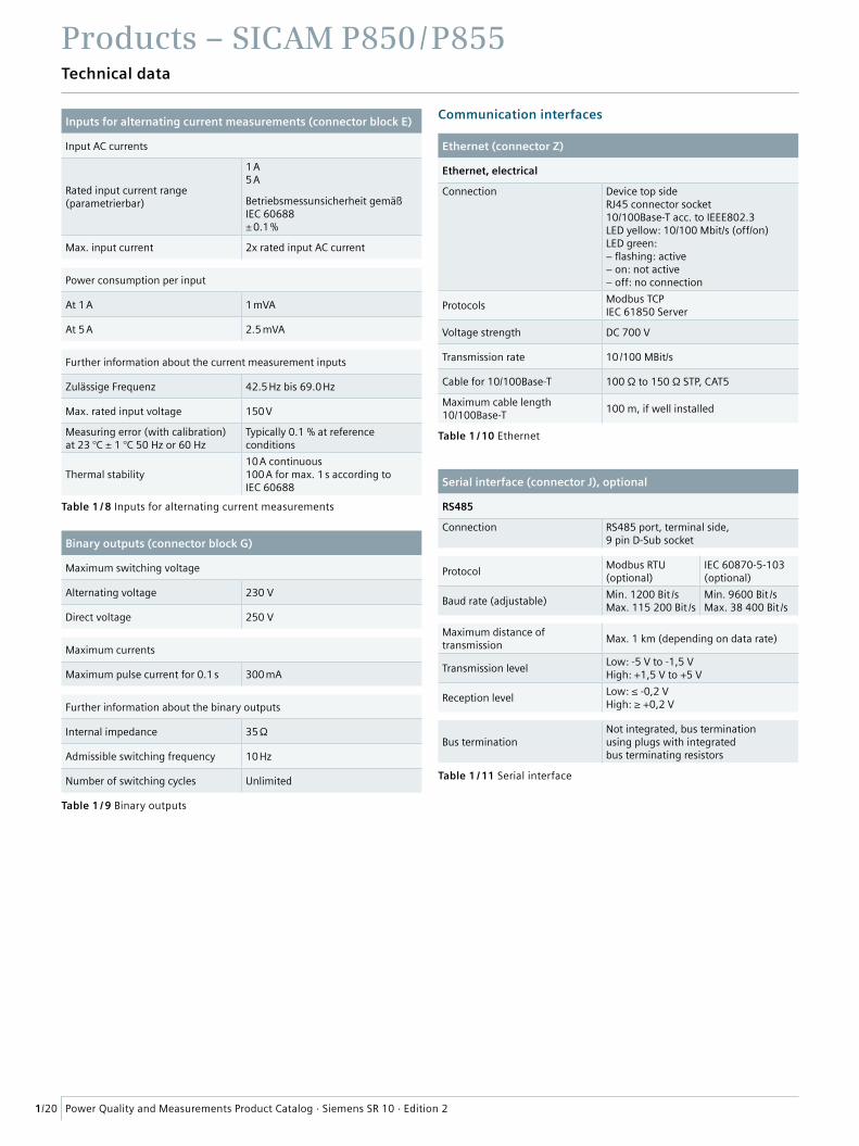
Communication interfacesInputs for alternating current measurements (connector block E)
Input AC currents
Rated input current range (parametrierbar)
1 A5 A
Betriebsmessunsicherheit gemäß IEC 60688± 0.1 %
Max. input current 2x rated input AC current
Power consumption per input
At 1 A 1 mVA
At 5 A 2.5 mVA
Further information about the current measurement inputs
Zulässige Frequenz 42.5 Hz bis 69.0 Hz
Max. rated input voltage 150 V
Measuring error (with calibration) at 23 °C ± 1 °C 50 Hz or 60 Hz
Typically 0.1 % at reference conditions
Thermal stability10 A continuous100 A for max. 1 s according to IEC 60688
Binary outputs (connector block G)
Maximum switching voltage
Alternating voltage 230 V
Direct voltage 250 V
Maximum currents
Maximum pulse current for 0.1 s 300 mA
Further information about the binary outputs
Internal impedance 35 Ω
Admissible switching frequency 10 Hz
Number of switching cycles Unlimited
Ethernet (connector Z)
Ethernet, electrical
Connection Device top sideRJ45 connector socket10/100Base-T acc. to IEEE802.3LED yellow: 10/100 Mbit/s (off/on)LED green:− flashing: active− on: not active− off: no connection
ProtocolsModbus TCPIEC 61850 Server
Voltage strength DC 700 V
Transmission rate 10 /100 MBit/s
Cable for 10/100Base-T 100 Ω to 150 Ω STP, CAT5
Maximum cable length10/100Base-T
100 m, if well installed
Serial interface (connector J), optional
RS485
Connection RS485 port, terminal side, 9 pin D-Sub socket
ProtocolModbus RTU(optional)
IEC 60870-5-103(optional)
Baud rate (adjustable)Min. 1200 Bit /sMax. 115 200 Bit /s
Min. 9600 Bit /sMax. 38 400 Bit /s
Maximum distance of transmission
Max. 1 km (depending on data rate)
Transmission levelLow: -5 V to -1,5 VHigh: +1,5 V to +5 V
Reception levelLow: ≤ -0,2 VHigh: ≥ +0,2 V
Bus terminationNot integrated, bus termination using plugs with integratedbus terminating resistors
Table 1 / 8 Inputs for alternating current measurements
Table 1 / 10 Ethernet
Table 1 / 11 Serial interface
Table 1 / 9 Binary outputs
Products – SICAM P850 / P855
1/21Power Quality and Measurements Product Catalog · Siemens SR 10 · Edition 2
Technical data
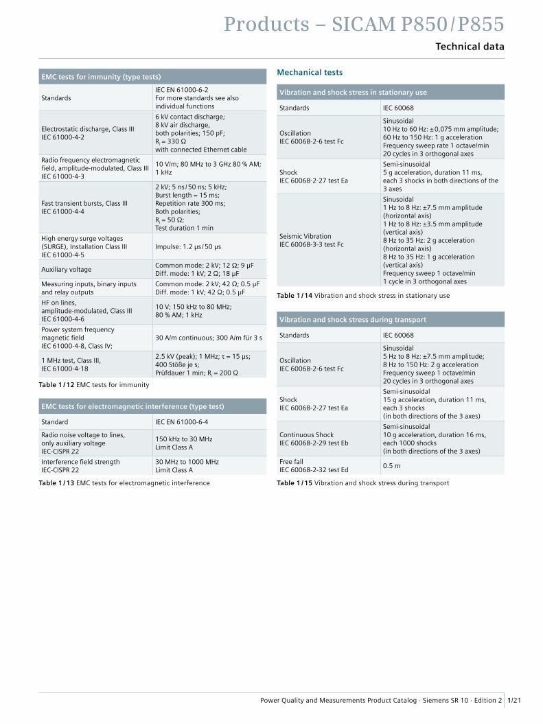
Mechanical testsEMC tests for immunity (type tests)
StandardsIEC EN 61000-6-2For more standards see also individual functions
Electrostatic discharge, Class IIIIEC 61000-4-2
6 kV contact discharge; 8 kV air discharge,both polarities; 150 pF; Ri = 330 Ωwith connected Ethernet cable
Radio frequency electromagnetic field, amplitude-modulated, Class IIIIEC 61000-4-3
10 V/m; 80 MHz to 3 GHz 80 % AM; 1 kHz
Fast transient bursts, Class IIIIEC 61000-4-4
2 kV; 5 ns / 50 ns; 5 kHz;Burst length = 15 ms;Repetition rate 300 ms;Both polarities;Ri = 50 Ω;Test duration 1 min
High energy surge voltages (SURGE), Installation Class IIIIEC 61000-4-5
Impulse: 1.2 μs / 50 μs
Auxiliary voltageCommon mode: 2 kV; 12 Ω; 9 μFDiff. mode: 1 kV; 2 Ω; 18 μF
Measuring inputs, binary inputs and relay outputs
Common mode: 2 kV; 42 Ω; 0.5 μFDiff. mode: 1 kV; 42 Ω; 0.5 μF
HF on lines, amplitude-modulated, Class IIIIEC 61000-4-6
10 V; 150 kHz to 80 MHz; 80 % AM; 1 kHz
Power system frequency magnetic fieldIEC 61000-4-8, Class IV;
30 A/m continuous; 300 A/m für 3 s
1 MHz test, Class III, IEC 61000-4-18
2.5 kV (peak); 1 MHz; τ = 15 μs;400 Stöße je s;Prüfdauer 1 min; Ri = 200 Ω
EMC tests for electromagnetic interference (type test)
Standard IEC EN 61000-6-4
Radio noise voltage to lines, only auxiliary voltageIEC-CISPR 22
150 kHz to 30 MHz Limit Class A
Interference field strengthIEC-CISPR 22
30 MHz to 1000 MHz Limit Class A
Vibration and shock stress in stationary use
Standards IEC 60068
OscillationIEC 60068-2-6 test Fc
Sinusoidal10 Hz to 60 Hz: ± 0,075 mm amplitude; 60 Hz to 150 Hz: 1 g accelerationFrequency sweep rate 1 octave/min 20 cycles in 3 orthogonal axes
ShockIEC 60068-2-27 test Ea
Semi-sinusoidal5 g acceleration, duration 11 ms, each 3 shocks in both directions of the 3 axes
Seismic VibrationIEC 60068-3-3 test Fc
Sinusoidal1 Hz to 8 Hz: ±7.5 mm amplitude (horizontal axis)1 Hz to 8 Hz: ±3.5 mm amplitude (vertical axis)8 Hz to 35 Hz: 2 g acceleration (horizontal axis)8 Hz to 35 Hz: 1 g acceleration (vertical axis)Frequency sweep 1 octave/min1 cycle in 3 orthogonal axes
Vibration and shock stress during transport
Standards IEC 60068
OscillationIEC 60068-2-6 test Fc
Sinusoidal5 Hz to 8 Hz: ±7.5 mm amplitude;8 Hz to 150 Hz: 2 g accelerationFrequency sweep 1 octave/min20 cycles in 3 orthogonal axes
ShockIEC 60068-2-27 test Ea
Semi-sinusoidal15 g acceleration, duration 11 ms,each 3 shocks (in both directions of the 3 axes)
Continuous ShockIEC 60068-2-29 test Eb
Semi-sinusoidal10 g acceleration, duration 16 ms,each 1000 shocks (in both directions of the 3 axes)
Free fallIEC 60068-2-32 test Ed
0.5 m
Table 1 / 12 EMC tests for immunity
Table 1 / 13 EMC tests for electromagnetic interference Table 1 / 15 Vibration and shock stress during transport
Table 1 / 14 Vibration and shock stress in stationary use
Products – SICAM P850 / P855
1/22 Power Quality and Measurements Product Catalog · Siemens SR 10 · Edition 2
Technical data
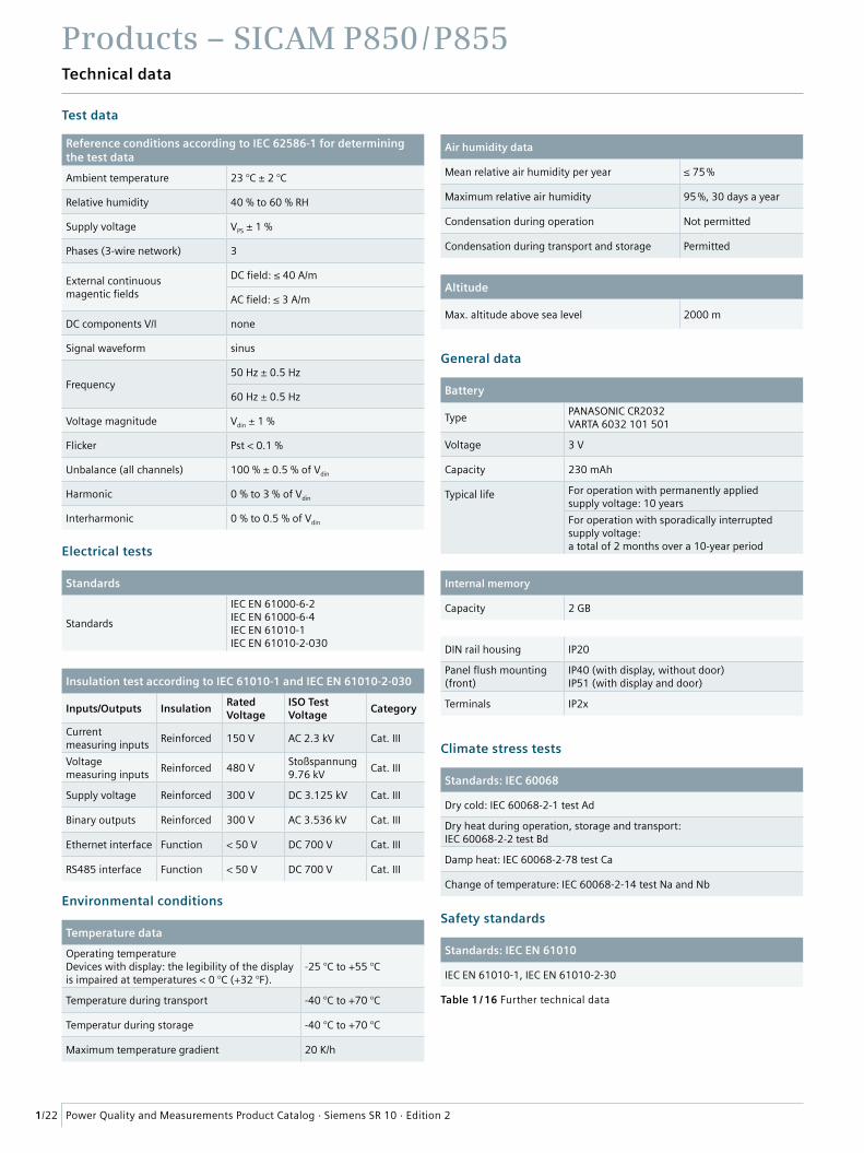
Test data
Reference conditions according to IEC 62586-1 for determining the test data
Ambient temperature 23 °C ± 2 °C
Relative humidity 40 % to 60 % RH
Supply voltage VPS ± 1 %
Phases (3-wire network) 3
External continuous magentic fields
DC field: ≤ 40 A/m
AC field: ≤ 3 A/m
DC components V/I none
Signal waveform sinus
Frequency50 Hz ± 0.5 Hz
60 Hz ± 0.5 Hz
Voltage magnitude Vdin ± 1 %
Flicker Pst < 0.1 %
Unbalance (all channels) 100 % ± 0.5 % of Vdin
Harmonic 0 % to 3 % of Vdin
Interharmonic 0 % to 0.5 % of Vdin
Environmental conditions
Temperature data
Operating temperatureDevices with display: the legibility of the display is impaired at temperatures < 0 °C (+32 °F).
-25 °C to +55 °C
Temperature during transport -40 °C to +70 °C
Temperatur during storage -40 °C to +70 °C
Maximum temperature gradient 20 K/h
General data
Battery
TypePANASONIC CR2032VARTA 6032 101 501
Voltage 3 V
Capacity 230 mAh
Typical life For operation with permanently applied supply voltage: 10 years
For operation with sporadically interruptedsupply voltage:a total of 2 months over a 10-year period
Internal memory
Capacity 2 GB
DIN rail housing IP20
Panel flush mounting (front)
IP40 (with display, without door)IP51 (with display and door)
Terminals IP2x
Climate stress tests
Standards: IEC 60068
Dry cold: IEC 60068-2-1 test Ad
Dry heat during operation, storage and transport:IEC 60068-2-2 test Bd
Damp heat: IEC 60068-2-78 test Ca
Change of temperature: IEC 60068-2-14 test Na and Nb
Safety standards
Standards: IEC EN 61010
IEC EN 61010-1, IEC EN 61010-2-30
Electrical tests
Standards
Standards
IEC EN 61000-6-2IEC EN 61000-6-4IEC EN 61010-1IEC EN 61010-2-030
Insulation test according to IEC 61010-1 and IEC EN 61010-2-030
Inputs/Outputs InsulationRatedVoltage
ISO Test Voltage
Category
Current measuring inputs
Reinforced 150 V AC 2.3 kV Cat. III
Voltage measuring inputs
Reinforced 480 VStoßspannung9.76 kV
Cat. III
Supply voltage Reinforced 300 V DC 3.125 kV Cat. III
Binary outputs Reinforced 300 V AC 3.536 kV Cat. III
Ethernet interface Function < 50 V DC 700 V Cat. III
RS485 interface Function < 50 V DC 700 V Cat. III
Air humidity data
Mean relative air humidity per year ≤ 75 %
Maximum relative air humidity 95 %, 30 days a year
Condensation during operation Not permitted
Condensation during transport and storage Permitted
Altitude
Max. altitude above sea level 2000 m
Table 1 / 16 Further technical data
Products – SICAM P850 / P855
1/23Power Quality and Measurements Product Catalog · Siemens SR 10 · Edition 2
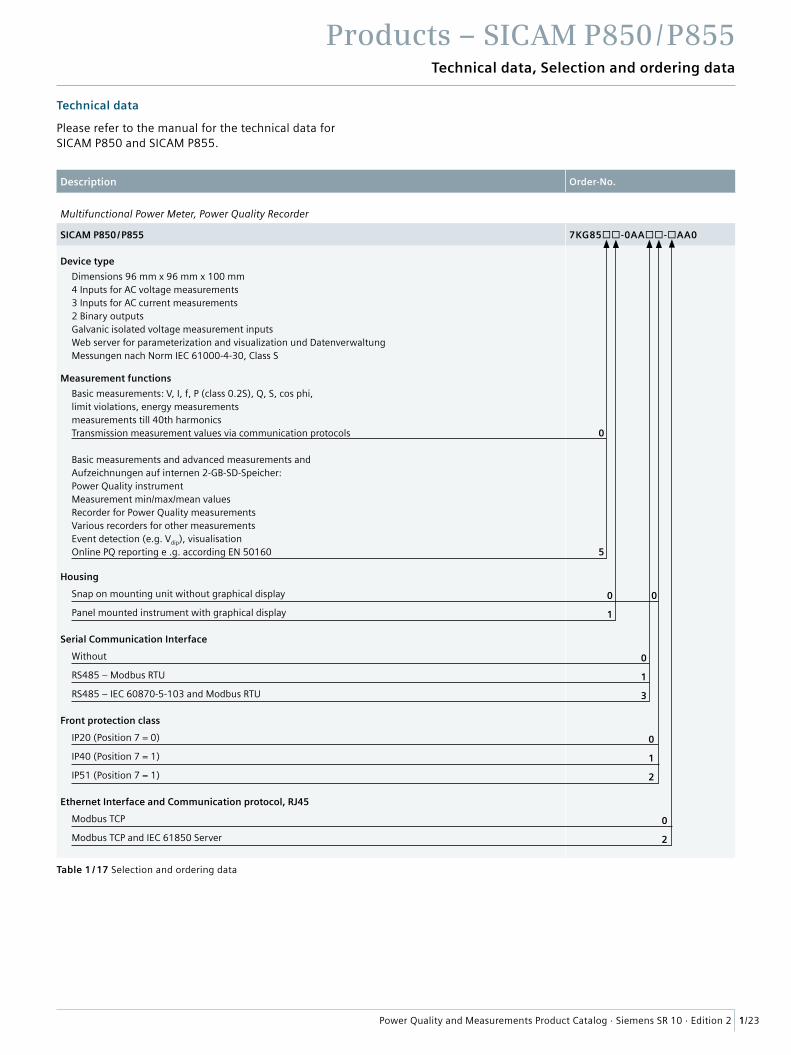
Technical data, Selection and ordering data
Description Order-No.
Multifunctional Power Meter, Power Quality Recorder
SICAM P850 / P855 7KG85-0AA-AA0
Device type
Dimensions 96 mm x 96 mm x 100 mm4 Inputs for AC voltage measurements3 Inputs for AC current measurements2 Binary outputsGalvanic isolated voltage measurement inputsWeb server for parameterization and visualization und Datenverwaltung Messungen nach Norm IEC 61000-4-30, Class S
Measurement functions
Basic measurements: V, I, f, P (class 0.2S), Q, S, cos phi, limit violations, energy measurementsmeasurements till 40th harmonicsTransmission measurement values via communication protocols 0
Basic measurements and advanced measurements and Aufzeichnungen auf internen 2-GB-SD-Speicher: Power Quality instrumentMeasurement min/max/mean valuesRecorder for Power Quality measurementsVarious recorders for other measurementsEvent detection (e.g. Vdip), visualisationOnline PQ reporting e .g. according EN 50160 5
Housing
Snap on mounting unit without graphical display 0 0
Panel mounted instrument with graphical display 1
Serial Communication Interface
Without 0
RS485 – Modbus RTU 1
RS485 – IEC 60870-5-103 and Modbus RTU 3
Front protection class
IP20 (Position 7 = 0) 0
IP40 (Position 7 = 1) 1
IP51 (Position 7 = 1) 2
Ethernet Interface and Communication protocol, RJ45
Modbus TCP 0
Modbus TCP and IEC 61850 Server 2
Table 1 / 17 Selection and ordering data
Technical data
Please refer to the manual for the technical data for SICAM P850 and SICAM P855.
Products – SICAM P850 / P855
1/24 Power Quality and Measurements Product Catalog · Siemens SR 10 · Edition 2