ENERGY AND SYSTEM SCALING LAWS FOR A HIGH …
23
Particle Accelerators 1984 Vol. 15 pp. 221-243 0031-2460/84/1504/0221 $18.50/0 © Gordon and Breach, Science Publishers, Inc. Printed in the United States of America ENERGY AND SYSTEM SCALING LAWS FOR A HIGH-CURRENT RACETRACK INDUCTION ACCELERATOR A. A. MONDELLI, Science Applications, Inc., McLean, VA 22102 and c. W. ROBERSON, Office of Naval Research, Arlington, VA 22217 (Received May 20, 1983; in final form December 30, 1983) A high-current cyclic electron accelerator capable of accelerating several kiloamperes of electron current is described. The accelerating elements of the device are linear induction modules, which match well to high- current operation. A racetrack configuration is utilized to return the electrons to the induction modules, thereby providing electron acceleration to an energy given by the gap voltage multiplied by the number of electron transits during the total pulse duration of the induction modules. The bends are stabilized against toroidal drifts due to field curvature and gradients by imposing an I = 2 stellaratorfield to average the drift motion. This field is analogous to an alternating-gradient focusing field. It provides containment of particles up to a maximum energy E MAX above which the orbits become too large to fit within the toroidal chamber. For a IO-cm diameter chamber on a I-meter radius bend, the maximum energy is approximately 1 MeV per kilogauss of guide field. For a 3-meter bend, E MAX 2.3 MeV/kG. This scaling sets an upper limit of 50 MeV for this configuration, before the size or field required becomes excessive. To move beyond this limit, a vertical magnetic field may be utilized to cancel the toroidal forces at a particular energy. This field must be increased as the particles are accelerated. In this configuration, the stellarator windings provide a tolerance in the allowed mismatch between the vertical field and the particle energy. At high energy, the stellarator field provides a bandwidth of stability for the vertical field around its matched value, B zo = 34 KG· E/R, where E is the particle energy in GeV and R is the major radius in meters. A simple model for a racetrack induction accelerator (RIA) has been used to derive the system scaling for size and weight as a function of beam particle energy. I. INTRODUCTION Particle accelerators have been developed as low-current high-energy machines or as low-voltage high-current devices such as Marx pulse-line systems. Induction ac- celerators have the potential of both high-current and high-voltage operation. In this paper, the energy scaling laws of the Racetrack Induction Accelerator! (RIA) are determined and its operating principles are discussed. This device is a cyclic accelerator that is capable of high-current operation. Long-pulse induction-linac technology is used to obtain short acceleration times. The RIA,circulates a high-current beam through a linear induction module. The voltage gain relation isV == V M TM/t, where V M is the voltage gain per pass, T M is the module pulse duration and t is the transit time of the beam around the accelerator. 221
Transcript of ENERGY AND SYSTEM SCALING LAWS FOR A HIGH …

Particle Accelerators1984 Vol. 15 pp. 221-2430031-2460/84/1504/0221 $18.50/0
© Gordon and Breach, Science Publishers, Inc.Printed in the United States of America
ENERGY AND SYSTEM SCALING LAWSFOR A HIGH-CURRENT RACETRACK
INDUCTION ACCELERATOR
A. A. MONDELLI,
Science Applications, Inc., McLean, VA 22102
and
c. W. ROBERSON,
Office of Naval Research, Arlington, VA 22217
(Received May 20, 1983; in final form December 30, 1983)
A high-current cyclic electron accelerator capable of accelerating several kiloamperes of electron current isdescribed. The accelerating elements of the device are linear induction modules, which match well to highcurrent operation. A racetrack configuration is utilized to return the electrons to the induction modules,thereby providing electron acceleration to an energy given by the gap voltage multiplied by the number ofelectron transits during the total pulse duration of the induction modules.
The bends are stabilized against toroidal drifts due to field curvature and gradients by imposing an I = 2stellarator field to average the drift motion. This field is analogous to an alternating-gradient focusing field. Itprovides containment of particles up to a maximum energy EMAX above which the orbits become too large tofit within the toroidal chamber. For a IO-cm diameter chamber on a I-meter radius bend, the maximumenergy is approximately 1 MeV per kilogauss of guide field. For a 3-meter bend, EMAX ~ 2.3 MeV/kG. Thisscaling sets an upper limit of ~ 50 MeV for this configuration, before the size or field required becomesexcessive.
To move beyond this limit, a vertical magnetic field may be utilized to cancel the toroidal forces at aparticular energy. This field must be increased as the particles are accelerated. In this configuration, thestellarator windings provide a tolerance in the allowed mismatch between the vertical field and the particleenergy. At high energy, the stellarator field provides a bandwidth of stability for the vertical field around itsmatched value, Bzo = 34 KG· E/R, where E is the particle energy in GeV and R is the major radius inmeters.
A simple model for a racetrack induction accelerator (RIA) has been used to derive the system scaling forsize and weight as a function of beam particle energy.
I. INTRODUCTION
Particle accelerators have been developed as low-current high-energy machines or aslow-voltage high-current devices such as Marx pulse-line systems. Induction accelerators have the potential of both high-current and high-voltage operation.
In this paper, the energy scaling laws of the Racetrack Induction Accelerator! (RIA)are determined and its operating principles are discussed. This device is a cyclicaccelerator that is capable of high-current operation. Long-pulse induction-linactechnology is used to obtain short acceleration times. The RIA ,circulates a high-currentbeam through a linear induction module. The voltage gain relation isV == VM TM/t,where VM is the voltage gain per pass, TM is the module pulse duration and t is thetransit time of the beam around the accelerator.
221
222 A. A. MONDELLI AND C. W. ROBERSON
At present, the linear induction accelerator is the most common high-voltage andhigh-current system in existence. Typically, iron or ferrite-core induction accelerationmodules are matched at a beam current of 1-2 kA. To achieve particle acceleration tohigh energy is mainly a matter of length and cost. Accelerating gradients are typically0.5 MeV/m, with some designs reaching as high as 1.0 MeV/m. The size of these machines implies large cost and requires large commitments of real estate. Costs in excessof $l/Volt are now common. Very high-current linear induction accelerators arepossible through the use of radial pulselines to drive the accelerating gaps, as has beenshown in the RADLAC2 accelerator at Sandia National Laboratories.
Various folded or cyclic accelerator designs have been proposed and studied in aneffort to achieve high-voltage and high-current systems without the~ huge cost andspace requirements of the induction linac. A conventional betatron, for example, iscurrent limited at injection, when the energy is low and the betatron fields are too smallto contain the beam space charge. A betatron with high-energy injector has beenstudied at Livermore and Berkeley in an effort to overcome the space-charge limit. Amore radical modification to the betatron, the so-called modified betatron, is understudy at the Naval Research Laboratory3 and at DC Irvine.4 In this approach, atoroidal magnetic field is used to contain the space charge at early times in theaccelerating cycle. The need for high-energy injection and a costly preaccelerator isthereby removed.
One approach for utilizing a linear induction accelerator to reach high energy is therecirculating linac concept, 5 which has been studied at the National Bureau ofStandards. In this approach, the· accelerator is in fact a folded linac, with the totalcharge carried through a linear induction module several times. On each transit thebeamlets are enclosed by drift tubes, which isolate them from each other while passingthrough the module. Since each induction module can accommodate only a smallnumber of these drift tubes, modules must be stacked to reach high voltage. Theracetrack induction accelerator, which is the subject of this report, is in fact a cyclicaccelerator in which the entire beam current circulates around a racetrack passingthrough linear induction modules on the straight legs of the racetrack.
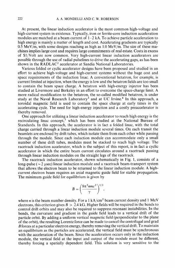
The racetrack induction accelerator, shown schematically in Fig. 1, consists of along-pulse (~ 2 Jlsec) linear induction module and a racetrack beam-transport systemthat allows the electron beam to be returned to the linear induction module. A highcurrent electron beam requires an axial magnetic guide field for stable propagation.The minimum guide field for equilibrium is given by
where n is the beam number density. For a 1 kA/cm2 beam current density and 1 MeVelectrons, this criterion gives B > 2.4 kG. Higher fields will be required in the bends tocontrol drift orbits and may also be· required to suppress resonant instabilities. In thebends, the curvature· and gradient in the guide field leads to a vertical drift of theparticle orbit. By adding a uniform vertical magnetic field (perpendicular to the planeof the orbit), the resulting Lorentz force can be made to cancel the centrifugal and gradB forces at a particular electron energy, thereby removing the vertical drift. To maintainan equilibrium as the particles are accelerated, the vertical field must be synchronouswith the acceleration of the beam. Since the acceleration occurs only in the inductionmodule, the vertical field at the input and output of the module must be different,thereby forcing a spatially dependent field. This solution is very sensitive to the

RACETRACK INDUCTION ACCELERATOR
RACETRACK INDUCTION ACCELERATOR
TOROIDALMAGNETICFIELD
223
FIGURE 1 Schematic of Racetrack Induction Accelerator. Inset shows cross section of the field coilswhich generate toroidal, helical and vertical magnetic fields in the bends.
accuracy to which the vertical magnetic field can be made synchronous with theacceleration. Small field errors can result in rapid loss of particles.
The poor stability of the vertical-field solution is due to its requirement of exact localforce cancellation at a particular energy. Instead, it is possible to design a magneticfield configuration that provides cancellation of the spatially averaged force felt by anelectron in the bend over a band of particle energies. This configuration is provided bya quadrupole field that is twisted into a helix, as in an 1 = 2 stellarator. The helical fieldcauses the particle to circulate about the minor axis of the bend, so that in driftingvertically, it drifts toward the axis for half the time in the bend and away from the axisfor the other half. The net effect of this motion is to average the net drift displacement tozero. All particles with energies up to some maximum are contained within this fieldconfiguration. Very energetic particles will have drift orbits too large to fit within theminor cross-section of the device and will therefore not be contained. The stellaratorwinding in conjunction with the long-pulse induction module makes a fixed-fieldaccelerator up to the maximum particle energy. Since the focusing and confining fieldscan be independent of time, the pulse shape of the induction module can be arbitrary.
To accelerate particles to energies in excess of the maximum contained in a fixedfield system, a time-dependent vertical magnetic field may be employed on the bends, asdescribed above. In this configuration, having combined vertical and stellarator fields,the time-independent stellarator component provides an energy bandwidth of approximately the maximum energy of the fixed-field system, thereby relaxing the requirements on the vertical field in matching the particle energy in both space and time.
These two configurations allow two classes of accelerators to be identified. The fixedfield configuration is best suited for accelerating a multi-kiloamp beam to modest

224 A. A. MONDELLI AND C. W. ROBERSON
energies (up to 50 MeV). The combined vertical and stellarator field configurations is ahigh-energy system, capable of reaching energies several hundred MeV.
II. ENERGY SCALING FOR THE RACETRACKINDUCTION ACCELERATOR
In conventional low-current cyclic accelerators, the bending magnetic fields must besynchronous with the particle energy. To contain the space charge in a high-currentaccelerator requires an axial magnetic field, which introduces curvature and grad Bdrifts. These drifts can be canceled by imposing a vertical magnetic field synchronouswith the particle acceleration. Unlike a conventional accelerator, where an asynchronism in the bending field causes the particle to adjust its radial equilibrium position,an asynchronism in the vertical field of a high-current accelerator causes a verticaldisplacement which offers no new equilibrium.
In place of the vertical field, a twisted quadrupole field provides a cancellation of theaverage force felt by a particle in traversing a bend. This technique avoids the problemsof field synchronism because the particle drifts average to zero for all energies below amaximum. The bending and confining fields in this case are independent of time. Thetwisted quadrupole configuration is analogous to an alternating-gradient strongfocusing system. This configuration, including the axial magnetic field, is an I == 2stellarator field, which was designed to control particle drifts in magnetic-confinementfusion. 6 ,7
F or detailed studies of the particle dynamics in a racetrack, a numerical model isrequired to integrate the fully relativistic single-particle equations of motion,
d edt (ymv) == - ~v x B,
where y == (1 - v2/ c2 ) -1/2 and B is the externally applied magnetic field. The actual
structure of B(x) may be found in several ways, but the first approach has been to use ananalytical approximation for the field.
The magnetic scalar potential for a toroidal stellarator field, to first order in theinverse aspect ratio, is given by8
«1>k,9,s) = BO{S + ~11(x)sin[I(9 - ets)]
- k€12 [x 21/(x) - x(1 + l)11(x)]sin[(1 + 1)9 - lets]4/rt
- k€12 [x 21,'(x) - x(1 - 1)II(x)]sin[(l - 1)9 - lets]4/rt
*+ €I + 1 II + 1(x)sin[(l + 1)8 - Irts]rt
+ €~ 1 11- 1 (x)sin[(l - 1)9 - letS]},

RACETRACK INDUCTION ACCELERATOR 225
where x = Irlvr, rlv = 2nlL, L is the pitch length of the helical field, k = IIRo, and Ro isthe major radius of the torus. €[± 1 is given by
* _ k€l [€1±1 X02J
€1+1-- --+-4 '- rlv €l
€l± 1
€l
where Xo = Irlvr0 and r0 is the minor radius of the helical current sheet that generatesthe field. A more general form of the potential would consist of a summation over I. Thenumerical work described here has been carried out entirely for the I = 2 stellaratorfield. The parameter €l measures the relative strength of the helical and solenoidal fieldcontributions. The helical field strength b is simply b = EIBo.
The magnetic field is found from this scalar potential by taking the toroidal gradient
B = a<Plr ar
1 a<PlBe =-;:88
a<PlBs = (1 - kr cos 8) &'
to first order in kr.The straight sections are modeled as regions of pure solenoidal field, Br = Be = 0,
Bz = Bs = Bo. The toroidal stellarator field is assumed to apply over the entire bend,which is modeled as a semi-circular region. A region of straight section adjacent to eachend of the bends is used to force a transition from a solenoidal to a stellarator fieldconfiguration. If the transition occurs in the regions S 1 ~ S ~ S2' the prescriptionfollowed is
El(S) = .E1[1 - _S_-_S_1 ]
S1 - S2
k(s) = k[l - S - Sl ]S2 - S1
in order to linearly remove the helical and toroidal field contributions. Other modeltransitions, such as parabolic and cosine, have also been tried with no observable effecton the particle trajectories. This model transition section does not satisfy Maxwell'sequations, however, and therefore introduces some non-adiabatic behavior in theparticle trajectories.
In a cylindrical stellarator field, given above with k = 0, some of the basic fieldstructure can be identified analytically. 7 The magnetic field lines migrate about amagnetic axis and ergotically fill a surface, called the magnetic surface. In an 1 = 1stellarator, the magnetic surfaces are approximately circles near a magnetic axis thathelically winds about the geometrical axis. For 1 2:: 2, the magnetic axis in a cylindrical
226 A. A. MONDELLI AND C. W. ROBERSON
stellarator coincides with the geometrical axis of the cylinder. For I == 2, the magneticsurfaces near the axis are elliptical, while for I == 3, the surfaces have a trefoil shape.Away from the magnetic axis a separatrix occurs, beyond which the surfaces are nolonger closed. As a magnetic field line propagates in the system, it migrates an angle t onthe magnetic surface as it moves a distance 2rcR along the axis. The angle t is therotational transform, given by
t(r) = ~ €? RP !£ (Il(X)I/(X))2rc 2 r dx x
~ €12C~l!YZSClRo(lClr)2(I-2{(l- 1) + (h;)2 + ...JFor I == 1 or 2, the rotational transform has a finite value at r == a and rises slowly withr. For I ~ 3, the rotational transform is zero at r == 0, and rises faster (higher shear) forlarger I as r increases.
The average radius rs of the separatrix for a straight helix is given by
and the ellipticity of the separatrix for I == 2 is given by
11. .. 1 + £l
E IptIClty == --1 - £l
near the magnetic axis. The volume enclosed by the separatrix is the useful volume ofthe accelerator. For I == 2, the separatrix radius rs goes to zero as £l goes to unity.
For high rotational transform, which is needed to cancel the particle drifts, a largevalue of £l is desired. The radius of the separatrix, however, becomes small (crrs ~ 0) for£l near unity, and has no real solution for £l > 1. The design is therefore a compromisebetween the need for a large rotational transform and the need for a reasonable volumewithin the separatrix.
After some trial and error, the design point chosen consists of an I == 2 stellaratorfield with ten helical field periods on a 100-cm radius circle (or cr == 0.1 cm -1) and£l == 0.7. This configuration given a rotational transform of t == 51t.
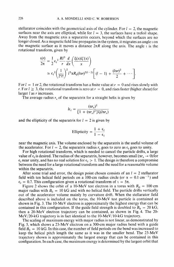
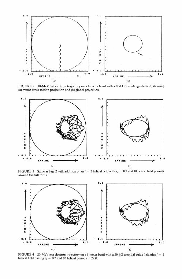
Figure 2 shows the orbit of a la-MeV test electron in a torus with Ro == 100 cmmajor radius with Bo == 10 kG and with no helical field. The particle drifts verticallyout of the accelerator volume mainly by curvature drift. When the stellarator fielddescribed above is included on the torus, the la-MeV test particle is contained asshown in Fig. 3. The la-MeV electron is approximately the highest energy that can becontained in this configuration. If the guide field strength is doubled to Bo == 20 kG,then a 20-MeV electron trajectory can be contained, as shown in Fig. 4. The 20MeV120-kG trajectory is in fact identical to the la-MeV110-kG trajectory.
The scaling of maximum energy with major radius is not linear, as demonstrated byFig. 5, which shows a 23-MeV electron on a 300-cm major radius bend with a guidefield Bo == 10 kG. In this case, the number of field periods on the bend was increased tokeep the helical pitch length the same as it was in the smaller bend. The 23-MeVtrajectory shown is approximately the largest energy that can be contained in thisconfiguration. In each case, the maximum energy is determined by the largest orbit that
".0
y
P
RIHE
- 5.0
- S. 0XPRIHE
O. I
y
P
RIHE
- O. 1
5. a -.5. 0------>7 XPRIHE
(a)
>.5. a
FIGURE 2 10-MeV test electron trajectory on a I-meter bend with a 10-kG toroidal guide field, showing(a) minor cross section projection and (b) global projection.
s.o
- 5.0- &.0 1.0
0.1
y
PRI
"E- D. I
- 2.0"""IH!!
2.0
(a) (b)
FIGURE 3 Same as Fig. 2 with addition of an I = 2 helical field with €l = 0.7 and 10 helical field periodsaround the full torus.
s.o
- 5.0- &.0 1.0
a. 1
y
PRI
"E- o. 1
- 2.0 1.0
(a) (b)
FIGURE 4 20-MeV test electron trajectory on a I-meter bend with a 20-kG toroidal guide field plus I = 2helical field having €[ = 0.7 and 10 helical periods in 2nR.

228 A. A. MONDELLI AND C. W. ROBERSON
- O. 1
S. 0 -". 0 ~ • 0
y
PRIHE
o. I
XPRIHE
S. 0
- 5.0
s.o
FIGURE 5 23-MeV test electron trajectory on a 3-meter bend with a 10-kG toroidal guide field plus I = 2helical field having €l = 0.7 and 30 helical periods in 21tR.
will fit inside the 5-cm minor radius of the accelerator. The scaling of the maximumenergy with major radius is shown in Fig. 6. The solid line on the figure is the function,
for Ro in meters. This function fits the computer results very accurately for 1 m SRo S 30 m, as shown on the figure. This curve was generated for Bo = 10 kG, with thehelical field specified by €l = 0.7 and rt = 0.1 cm - 1
The racetrack configuration has also been tested, and Fig. 7 shows a 5-MeV electronthat is followed for approximately twenty transits of the accelerator. The particle is wellcontained, but its orbit grows slowly during the run, probably due to nonadiabaticitygenerated in the transition section.
To produce a field model for the racetrack that is not subject to model-dependentnonadiabatic behavior, it is necessary to construct the field from an actual surfacecurrent distribution. A simple modular design was achieved in the Tor-2 stellarator in
200 r-------r-------r---------,
'Y MAX 100
302010O-'-----------------~o
FIGURE 6 Scaling of maximum energy with major radius for Bo = 10 kG, €l = 0.7, r:1 = 0.1 cm- 1

RACETRACK INDUCTION ACCELERATOR 229
1.0
1.1
(b)X"'UHE
"""IH!
y
PRIHE
y
PRIHE
O. 1
o. 1
- o. I
- 2.0
- O. I- 1.5
I. a(a)
X"'UH!
6.0
- 5.0- 1.0
(c)
FIGURE 7 5-MeV test electron trajectory on a racetrack, showing (a) minor-cross-section projection,(b) global projection viewed from side, (c) global projection viewed from end. Bendshave I = 2 helical fieldwith El = 0.7 and 10 helical periods in 21tR.
the Soviet Union. 9 Several other modular stellarator systems have been devised. IO TheTor-2 system generates an l = 2 stellarator field with coils of elliptical cross section,which are rotated relative to each other to produce a helical configuration. By itself, thiscoil design is limited to small values of €l' since the helical coils will produce a largetoroidal field component. A more flexible system consists of surrounding the ellipticalcoil with a circular coil that carries a current in the opposite sense, thereby partiallycanceling the toroidal field component due to the elliptical coil. This design has beenutilized to construct a modular field-coil model for a racetrack stellarator and avoidsthe difficulty of analytically modeling the transition section.
The basic scaling laws in size, energy and fields for a fixed-field racetrack inductionaccelerator may be expressed as
EMAX ~ 1.15 Roo.60S MeV/kG,
for 1 m ~ Ro ~ 30 m, and the accelerator wall located at a minor radius of 5 em. Thisconfiguration therefore provides a means of achieving moderate energy performancewith a system having no time-dependent fields.

230 A. A. MONDELLI AND C. W. ROBERSON
The fixed-field accelerator racetrack requires excessive nlagnetic-field energy toachieve particle energies significantly above 50 MeV in a practical device. It is possibleto operate the racetrack as a high-energy induction accelerator by adding a timedependent vertical magnetic field to the bends. The vertical field must be madesynchronous with the particle energy. The stellarator field now provides an energybandwidth, which is equivalent to a bandwidth in allowed mismatch of the vertical fieldand the particle energy. The energy bandwidth is approximately equal to the maximumenergy contained in the fixed-field configuration. As the particle accelerates, therefore,the accuracy required for the vertical field to lie within the allowed bandwidthincreases.
If the vertical field does not lie in the allowed band, the particle will execute a verticalcross-field drift. In this drift motion the particle will sample radial positions that liewithin the Larmor orbit associated with the axial magnetic field. If the vertical fielderror is small enough that the particle can achieve a new equilibrium position within itsLarmor orbit, it will be contained. The accuracy ~B/B required for the verticalmagnetic field is thus given by
~B < max {PL ~E}B R' E
where PL is the Larmor radius, R is the major radius of the bend, ~E is the energybandwidth provided by the stellarator field, and E is the particle energy. At high energy,when ~E/E becomes small, the Larmor radius becomes large. These criteria combineto permit ~B/B in excess of 1% for energies up to a nominal 1 GeV.
The vertical magnetic field can be supplied by toroidal windings arranged in a cos edistribution on the toroidal wall in the bends. This configuration provides a verticalmagnetic field with high uniformity. A difficult design problem for the racetrack is thetermination of these windings where the bends meet the straight sections. In thestraight sections, of course, the vertical magnetic field would cause rapid particle lossdue to uncompensated drifts. In fact, at each point in the transition from bend tostraight the vertical field must cancel theloeal curvature and grad B drifts to highprecision.
One approach to this problem is to design the bends with a variable radius ofcurvature, i.e., not a semicircular bend, so that the local radius of curvature can bematched to the fall-off in the vertical magnetic field. In practice, this design would beaccomplished by computing the vertical magnetic field for a particular coil andtermination configuration, and subsequently calculating the shape required for thebend so that the local magnetic field provides cancellation of the local curvature andgrad B drifts.
The vertical magnetic field may be modeled as
including the vertical field index n, to first-order in the inverse aspect ratio.. Unlessotherwise noted, the vertical field is assumed uniform (n == 0). Runs with finite fieldindex have been made and show performance that is insensitive to the field index.
5.0
y
PRIHE
- S.D- 5.0
o • 1
y
PR
IHE
- D. 1
- 2.0
RACETRACK INDUCTION ACCELERATOR
XPRIHE
XPRIHE
:>
:>
5.0
2.0
231
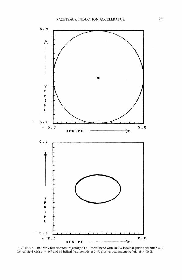
FIGURE 8 100-MeV test electron trajectory on a I-meter bend with 10-kG toroidal guide field plus l = 2helical field with €l = 0.7 and 10 helical field periods in 21tR plus vertical magnetic field of 3400 G.
232 A. A. MONDELLI AND C. W. ROBERSON
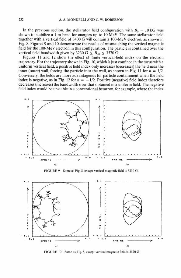
In the previous section, the stellarator field configuration with Bo == 10 kG wasshown to stabilize a 1-m bend for energies up to 10 MeV. The same stellarator fieldtogether with a vertical field of 3400 G will contain a 100-MeV electron, as shown inFig. 8. Figures 9 and 10 demonstrate the results of mismatching the vertical magneticfield for the 100-MeV electron in this configuration. The particle is contained over thevertical field bandwidth given by 3230 G ~ Bzo S 3570 G.
Figures 11 and 12 show the effect of finite vertical-field index on the electrontrajectory. For the trajectory shown in Fig. 10, which isjust confined in the torus with auniform vertical field, a positive field index only increases (decreases) the field near theinner (outer) wall, forcing the particle into the wall, as shown in Fig. 11 for n = 1/2.Conversely, the fields are more advantageous for particle containment when the fieldindex is negative, as in Fig. 12 for n == -1/2. Positive (negative) field index thereforedecreases (increases) the bandwidth over that obtained in a uniform field. The negativefield index would be unstable in a conventional betatron, for example, where the index
5. 0
y
P
R
IM
E
- s. 0
- 5. 0XPRIHE
O. 1
y
PRIM
E
- O. 1
5.0 - ~.O
~---->~ XPR I HE
(a) (b)
5. 0
FIGURE 9 Same as Fig. 8, except vertical magnetic field is 3230 G.
s. 0
y
P
R
IHE
- 5.0- 5. 0
XPRIHE
D. 1
y
PRIH
E
- o. 1
5.0 - ~.o
-----?~ XPR I HE
(a)
~. 0
FIGURE 10 Same as Fig. 8, except vertical magnetic field is 3570 G

RACETRACK IN"DUCTIONACCELERATOR 233
5.0
y
PR
IHE
- 5.0
- 5.0>
5 .. 0
FIGURE 11(a) Same as Fig. 10, except n = 1/2.
o• 1
y
PR
IHE
- O. 1
- 1. 5XPRIHE
FIGURE I1(b)
>1 • 5

234 A. A. MONDELLI AND C. W. ROBERSON
s.o
y
PR
IHE
- S.D- 5.0
XPRIHE ::>5.0
FIGURE 12(a) Same as Fig. 10, except n = -1/2.
o • 1
y
PRIH·E
- D. 1
- 1.5XPR·I HE
FIGURE 12(b)
>1 .S
5.0
y
P
RIH
E
s. 0
- 5. 0XPRIHE
RACETRACK INDUCTION ACCELERATOR
0.1
y
P
R
I
HE
- O. 1
5.0 - 2.0----->~ XPRIHE
(a) (b)
FIGURE 13 Same as Fig. 9, except helical field is zero.
235
2.0
provides both vertical and horizontal focusing. The helical field provides an additionalstrong focusing that is independent of the vertical field index and allows stable particlebehavior over a broad range of field index.
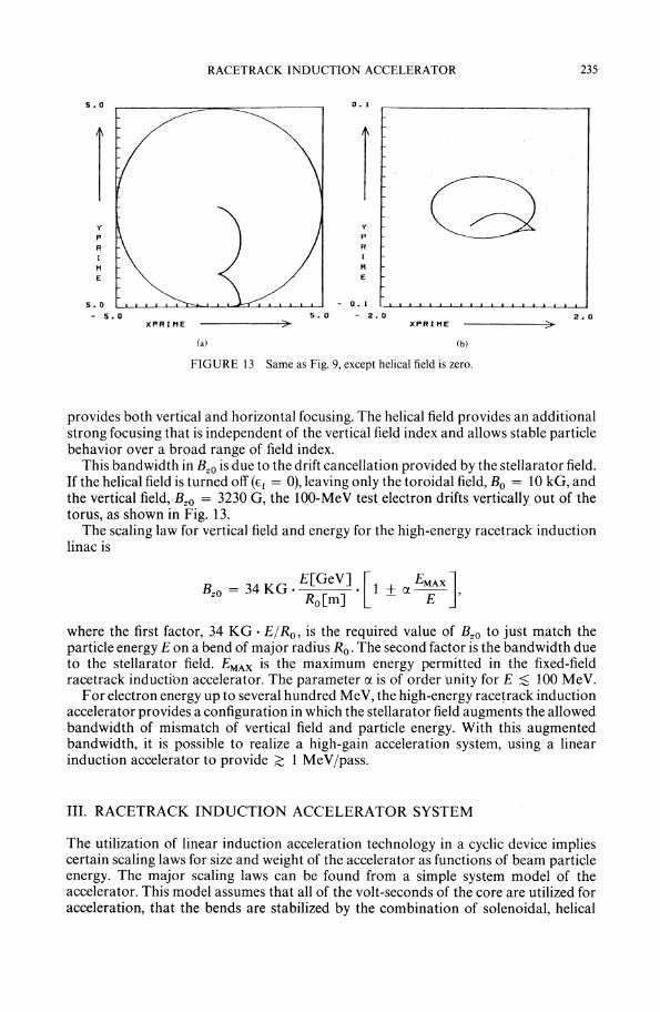
This bandwidth in Bzo is due to the drift cancellation provided by the stellarator field.If the helical field is turned off (€l= 0), leaving only the toroidal field,' Bo = 10 kG, andthe vertical field"Bzo = 3230 G, the 100-MeV test electron drifts vertically out of thetorus, as shown in Fig. 13.
The scaling law for vertical field and energy for the high-energy racetrack inductionlinac is
B = 34 KG - E[GeV] -[I + a. EMAXJzO Ro[m] - E '
where the first factor, 34 KG - EjRo, is the required value of Bzo to just match theparticle energy E on a bend of major radius Ro . The second factor is the bandwidth dueto the stellarator field. EMAX is the maximum energy permitted in the fixed-fieldracetrack inductibn accelerator. The parameter a. is of order unity for E ;$ 100 MeV.
For electron energy up to several hundred MeV, the high-energy racetrack inductionaccelerator provides a configuration in which the stellarator field augments the allowedbandwidth of mismatch of vertical field and particle energy. With this augmentedbandwidth, it is possible to realize a high-gain acceleration system, using a linearinduction accelerator to provide ;(: 1 MeVjpass.
III. RACETRACK INDUCTION ACCELERATOR SYSTEM
The utilization of linear induction acceleration technology in a cyclic device impliescertain scaling laws for size and weight of the accelerator as functions of beam particleenergy. The major scaling laws can be found from a simple system model of theaccelerator. This model assumes that all of the volt-seconds of the core are utilized foracceleration, that the bends are stabilized by the combination of solenoidal, helical

236 A. A. MONDELLI AND C. W. ROBERSON
and vertical fields described in the previous sections, and that the induction moduleitself is stable to the circulating particle beam. These assumptions about the stability ofthe device will be discussed in greater detail near the end of this section.
Figure 14 shows a schematic drawing of the accelerator system to identify thequantities of interest. Each straight section has length L and each bend is assumed to besemi-circle of radius R. Each straight section contains an induction accelerator withtotal core length Lc and core radius Rc • Particles are assumed to travel at speed c, thespeed of light. The particle transit time t on the racetrack is then
2L + 2nRl' ==----
C
The number of volt-seconds VM TM in the induction modules is given by
Here 2Rc Lc is the total cross-sectional area of the cores on both legs of the racetrack.The constant K is the effective change in magnetic field ~B over the area 2Rc Lc • Thetheoretical maximum value of K is 3 Tesla, corresponding to a solid iron core which isswung from - Bs to +Bs ' where Bs ~ 1.5 T is the saturation field for iron. In fact,insulation and packing factors limit the volume of iron in the core, and K == 1.5 Twillbe utilized for this discussion.
The voltage VM is the total energy gain per pass and may be distributed over severalgaps. Four gaps are envisioned, to optimize the core packing factor. One gap would belocated at each end of each straight section. The average voltage gradient g, in theinduction accelerator modules is given by
and the total acceleration time TM is then
~------Lc -----~
CORE
CORE
\~"'----L -\FIGURE 14 Schematic drawing of accelerator for system scaling study.

RACETRACK INDUCTION ACCELERATOR 237
At this point, it should be noted that the final particle energy V is independent of thegradient g,
VM TM KcRcLcV=--=---
1 L + nR
The number of transits N required to achieve the particle energy V does depend on gbecause
TM KcRcN--------- 1 - 2g(L + rcR)"
The voltage-gain relationship, V1 = VM TM , that all the volt-seconds be utilized,leads to some interesting scaling laws. This requirement may be written as
KcRcLcL + rcR = V .
Since the system is constrained to have L ~ Lc and R ~ Rc ' i.e., the cores must fitwithin the racetrack, it is reasonable to examine this system for fixed values of the ratiosRclRand LclL as parameters. In this case it is possible to solve for the length L as afunction of the radius R to obtain
RIRoL = rcRo R
Ro
where
With this relationship between Land R, the transit time 1 may be expressed as
2L + 2nR1=----
c
2rcRo (RIRO)2
c R--1Ro
This expression is interesting because it yields a minimum transient time 1 M , which thusoptimizes the compactness of the system. At minimum 1, the racetrack is described by
8nRo1 M =-
C
R = 2Ro
L = 2rcRo.

238 A. A. MONDELLI AND C. W. ROBERSON
The core dimensions at minimum 't are given by
R = 2Roc RjR
c
L = 21tRoc LjL
c•
The number of volt-seconds is then
and the core volume is
Since the main cost of the accelerator is the weight of iron, which is proportional to thecore vo~ume, the cost will scale as V 3
• These two equations may be used to express thecore volume in terms of volt-seconds,
(L/L )1/2(V; ~ )3/2Vol = 161t 2 __c ~ •R/Rc 81tK
The dependence of particle energy V, with volt-seconds and core volume is shown inFigs. 15 and 16 for various values of the ratios, R/Rc and L/Lo and for K = 1.5 Tesla,which corresponds to 50% packing of the core volume with iron.
The following table gives the parameters of a racetrack accelerator, which isoptimized in the sense that 't = 'tM , R = Rc and L = Lc • The design is for a 200 MeV
800 R(L 2--) =1Rc Lc
> 600Q)
~&...-......I
> 400
200
0200 400 600
CORE VOLUME (m 3 )
FIGURE 15 Final particle energy vs volt-seconds in cores.

RACETRACK INDUCTION ACCELERATOR 239
60 80 100
VMTM [V-S]
4020OL---..I.-.---..1..---...L-..---...J.-...--......I...-----------
120
800
~=I,----, 600 RCLC>
Q)
~>
400
200
FIGURE 16 Final particle energy vs core volume.
electron accelerator using K = 1.5 Tesla and g = 179 kV1m (corresponding to1 MeVIpass):
R = 0.88 m
L = 2.8 m
VM TM = 7.4 volt-sec
Core Volume = 13.6 m3
TM = 7.4 Jlsec
Beam Energy = 7.4 KJ for 1 kA.
The weight of the core in this case would be 51 MT (including the 50% core volumeutilization implicit in the value of K). For a l-kA beam, the capacitor bank required todrive the cores is 15 kJ, corresponding to ~ 50% core losses,which is typical of this typeof system.
IV. DISCUSSION
Injection into a high-current toroidal accelerator is a key problem. The closed fieldlines of the axial magnetic field that was introduced to contain the space charge of thebeam complicate the injector design. A number of experiments have been carried outwith varying degrees of success. These include, inductive chargingll
-15 magnetic
diverters, 16, 1 7 orbit reduction due to self field energy and drift injection. 18
Electron densities of 1010 cm - 3 (~100 microcoulombs of charge) have beeninjected13 into a magnetic torus by inductive charging. An inductive charging injectoris used on the high-current betatron experiment14
,15 at UC Irvine.

240 A. A. MONDELLI AND C. W. ROBERSON
Magnetic diverters open the toroidal field lines in the region of the injector for ashort period of time to allow electrons to enter. A self-synchronous scheme16 that usesthe magnetic field produced by the current in the cathode shank of a high-current diodeto divert field lines has been used successfully. Up to 50% of a 500-kV, 20-kA, 50-Jlsecbeam has been injected into a racetrack torus. 17
The force exerted on the curved field lines of a magnetic torus by a circulatingelectron beam will cause the beam to drift vertically (perpendicular to the plane of thetorus). This drift may be balanced by the addition of a vertical field. This field can beadjusted so that the F r x B4> is equal and opposite to the drift resulting from the curvedfield lines. Here Fr is the Lorentz force resulting from the azimuthal velocity and vertical magnetic field. If this equilibrium is upset, the beam will drift out vertically.Alternatively, by upsetting the equilibrium locally at the edge of the torus, the-beam canbe drifted into the torus across the field lines. This scheme is attractive for multiturn19injection as opposed to the magnetic diverter, which is attractive for single-turninjection.
The experiments discussed in Refs. 17 and 18 were performed by injecting the beaminto neutral gas, rather than at the hard vacuum which is desired for beam acceleration.Parallel injection of a nonneutral beam ring into a toroidal magnetic field in a vacuumhas been achieved. 19 A 450-keV, 16-kA, 25-Jlsec beam was injected into a 28-cm majorradius torus with a 5.5-cm inner radius. The trapped beam current was 300 A. Aquiescent equilibrium that lasted for 20 Jlsec was obtained. The beam made 3000revolutions around the torus.
The beam was not accelerated in any of the aforementioned experiments. Runawayelectrons have been observed in a racetrack stellarator,6 where the beam is born in thedevice and is charge-neutralized.
These experiments are cited as a partial summary of previous work on injection ofhigh-current beams into closed magnetic configurations. None of this prior experienceestablishes a solution to the injection problem, which will require a substantial exper~imental effort. An obvious advantage of the stellarator field configuration is that itallows a large bandwidth in energy mismatch at injection. In addition the externallyimposed rotational transform can be utilized in the injection scheme, since it allows thebeam to make many revolutions of the accelerator without returning to the injectorThe separatrix associated with the helical field provides additional flexibility ininjecting and trapping the electron beam.
The extraction problem, although also untried and nontrivial at high current, may beeasier than injection because at high energy the beam self-field forces are smaller andthe effect of the closed toroidal and stellarator fields is reduced. At the final energy, thebeam responds mainly to changes in the vertical field, which can be perturbed by akicker. For some applications, it may also be reasonable to use the beam in-situ, thereby avoiding the extraction issue altogether.
The high gain and corresponding short acceleration time for the racetrack inductionaccelerator reduce the impact of synchrotron radiation loss. The energy loss per passdue to synchrotron radiation for a particle of energy E in a torus of radius Ro is givenby
E 4 [GeV]Psync = 88 [] keY/pass.
Ro m
In a I-m torus, therefore, a I-GeV electron will lose 88 keYjpass. The racetrack losesapproximately the same energy since the straight sections produce a negligible amount

RACETRACK INDUCTION ACCELERATOR 241
of excess synchrotron radiation loss. Even at 1 GeV in a I-m bend, the gain per pass,Z 1 MeV/pass, in the racetrack far exceeds the energy loss to synchrotron radiation.The short time for acceleration also ensures that the integrated energy loading on thewalls due to synchrotron radiation will be negligible.
The discussion of this concept has so far centered on single-particle studies anddesign issues. In part, this emphasis is justified by the need to establish first that a singleparticle accelerator configuration can be built to the required energy, i.e., that theproposed device does not require collective effects. In part, though, this study has beenstructured as it has because of the enormous difficulty associated with generating selfconsistent equilibrium and stability analyses in the racetrack field configuration.Nevertheless, some statements on both these subjects can be made.
Self-consistent equilibria and stability of non-neutral systems have been studied inboth cylindrical and toroidal geometry for systems with toroidal fields only20 and forthe modified-betatron field configuration.21 ,22 No such study has included thestellarator field structure of the racetrack induction accelerator. The equilibriumstudies have found a slow beam drift rotation at the relativistic diocotron frequency,COd = COp2/2y2 con where cop is the beam plasma frequency, rop
2 == 4n ne2 /ym, and COc isthe cyclotron frequency, COc = eBo/ymc in the toroidal field, Bo . In the simplestapproximation, this drift may be regarded as a rigid rotation. The drift arises from theradial force due to the self fields, -e(Er - vzBe/c), crossed into the toroidal field. Incylindrical geometry, the Erand Be fields are almost equal, Be = vzEr/c, and the radialforce is then given by - eEr/y2. In toroidal geometry, the fields are modified to firstorder in the inverse aspect ratio, and force cancellation to I/y2 does not occur, i.e.,residual forces of order, - eEra/Ro, will exist in a toroidal system even at very high y.
The same results hold in a stellarator, but are complicated by the elliptical shape ofthe beam (for l = 2). In this case both the beam drift at frequency, rod' and the rotationaltransform due to the helical fields act to move the electrons about the minor axis of thetorus. These two motions may either add or subtract, and the performance of theaccelerator will probably depend on setting up the helix so that these two effects addconstructively. At this point it should be noted that the drift at rod does not providesufficient rotational transform at 10-kA beam strength to operate the accelerator abovea few MeV with I-m bends.
The single-particle trajectory code described above may be used to test whether thebeam self-fields destroy the accelerator bandwidth. In this case the code is modified toinclude the beam self-fields in a uniform beam model, as described by Chernin andSprangle,21 to first-order in the inverse-aspect ratio.
These fields have been added to the stellarator and toroidal fields described above toinclude the beam self-field effects in a torus, for a beam current of 10 kA and 2 cmradius. With the helix chosen to add to the rotational transform due to the beam driftmotion in its self-fields, the beam current is seen to have a small beneficial effect onconfinemen1. 1
The stability of the beam in the racetrack should be good. Stability studies for themodified betatron22 have shown favorable stability, provided the beam thermal spreadis of the order 10% or greater. The stellarator fields induce transverse motion, whichshould provide a strong stabilizing influence. In addition, the short acceleration timefavors the racetrack stability. Resistive-wall instabilities, for example, are too slow toaffect the racetrack accelerator if the wall is a good conductor.
The beam-breakup and image-displacement instabilities for a racetrack inductionaccelerator have been studied by Godfrey and Hughes.23 They considered a l-kA 40MeV electron RIA having a guide field of 2 kG and four accelerating gaps. Each gap

242 A. A. MONDELLI AND C. W. ROBERSON
had a transverse impedance of 15 Q and a cavity Q == 6, and provided an energy gainof .0.2 MeVjpass. With these parameters, the image-displacement mode growth isnegligible and the beam-breakup mode is limited to a total amplification of 3.6, whichis approximately one-third the growth rate of the negative-mass instability for theseparameters-.
V. SUMMARY
The high-current racetrack induction accelerator offers several advantages over otherhigh-current accelerator concepts. Its chief advantage is the high energy gain per passthat is made possible by using linear induction acceleration technology. This featureallows the accelerator to achieve a particular design energy with a short accelerationtime, thereby reducing the impact of instabilities and of synchrotron radiation.
The racetrack induction accelerator has several similarities to both the modifiedbetatron and the recirculating linac. It is a high-current cyclic induction accelerator,like the modified betatron, and it utilizes linear induction accelerator modules, like therecirculating linac. Unlike the modified betatron, however, the racetrack acceleratordoes not employ a vertical magnetic field for both bending and accelerating theparticles. This feature of a betatron configuration forces it to satisfy the flux condition,that the average vertical field enclosed by the orbit equal twice the field at the orbit. Onthe other hand, the betatron automatically provides synchronization of the verticalfield and the particle energy, which must be closely matched at injection. The fixedfield racetrack configuration, at modest energy, requires no synchronization of fields,while the high~energy racetrack must be independently synchronized within a bandwidth of particle energy.
The recirculating linac is a folded linear accelerator in which separate beam channelsare passed through the accelerating gap. In this accelerator, the final beam pulseduration is equal to the accelerator pulse length. The racetrack accelerator, on theother hand, delivers a beam pulse of duration equal to the transit time around thecircumference of the machine. The recirculating linac provides a large number ofaccelerated particles at modest energy. Since each particle can only traverse theaccelerating gaps a few times, the recirculating linac must stack accelerators to achievehigh energy particles. The racetrack induction accelerator uses the iron to obtain highvoltage, while the recirculating linac uses the same number of volt-seconds to achievea long pulse.
In summary, the racetrack induction accelerator offers a new configuration whichappears capable of reaching high voltage and high current. This concept extrapolateshigh-voltage linear induction accelerator technology into the multi-microsecondregime, without sacrificing the high current-handling capability of that technology.
The stellarator configuration allows us to design an interesting variation of thebetatron or the modified betatron by the addition of strong focusing. 24 The strongfocusing makes the accelerator less sensitive to mismatch between magnetic fields andparticle energy.
VI. ACKNOWLEDGMENTS
Discussions with S. Penner and M. Wilson of NBS, P. Palmadesso and members of theNRL Advanced Accelerator Project are appreciated. This work was supported by theNaval Research Laboratory.

REFERENCES
RACETRACK INDUCTION ACCELERATOR 243
1. C. W. Roberson, IEEE Trans. Nucl. Sci., NS-28, 3433 (1981); A. Mondelli and C. W. Roberson, NRLMemorandum Report 5008 (1983).
2. R. B. Miller et al., IEEE Trans. Nucl. Sci., NS-28, 3343 (1981).3. P. Sprangle and C. A. Kapetanakos, J. Appl. Phys., 49, 1 (1978).4. G. Barak et al., IEEE Trans. Nucl. Sci., NS-28, 3340 (1981).5. M. A. D. Wilson, IEEE Trans. Nucl. Sci., NS-28, 3375 (1981).6. K. M. Young, Plasma Physics, 16,119 (1974).7. K. Miyamoto, Nucl. Fusion, 18,243 (1978).8. 1. S. Danilkin, "Effect of Geometric Errors in the Magnet System on the Field Configuration in a
Stellarator", in Stellarators, Proc. of the P. N. Lebedev Physics Inst., D. V. Skobel'tsyn, editor,(Consultants Bureau, New York, c. 1974), Vol. 65, pp. 23ff.
9. M. A. Ivanovskii et ai., "The Tor-2 Stellarator", in Stellarators, Proc. of the P. N. Lebedev Physics Inst.,D. V. Skobel'tsyn, editor (Consultants Bureau, New York, c. 1974), Vol. 65, pp. 61ff.
10. T. K. Chu et ai., "Modular Coils: A Promising Toroidal Reactor Coil System", Princeton PlasmaPhysics Laboratory Report, PPPL-1796 (April, 1981).
11. G. S. Janes, Phys. Rev. Lett., 15, 135 (1965).12. 1. D. Daugherty, 1. E.,Eninger, and G. S. Janes, Phys. Fluids, 12, 2677 (1969).13. W. Clark, P. Korn, A. Mondelli, and N. Rostoker, Phys. Rev. Lett., 37, 592 (1976).14. S. Eckhouse, A. Fisher, and N. Rostoker, Phys. Rev. Lett., 42,94 (1979).15. G. Barak et ai., "High-Power Beams 81", Proc. of the 4th IntI. Top. Conf. on High-Power Electron and
Ion Beam Research and Technology (Palaiseau, France, June 29-July 3, 1981) Vol. II,_PP. 795ff.16. D. F. Brower, B. R. Kusse, and G. D. Meixel, Jr., IEEE Trans. on Plasma Sci., PS-2, 193 (1974).17. P. Gilad, B. R. Kusse, and T. R. Lockner, Phys. Rev. Lett., 33, 1275 (1974).18. J. Benford et ai., Phys. Rev. Lett., 31,346 (1973); 1. Benford, J. Guillory and C. Stallings, J. Appl. Phys., 45,
1657 (1974); J. Benford, B. Ecker, and V. Bailey, Phys. Rev. Lett., 33, 574 (1974).19. A. Mohri, M. Masuzaki, T. Tsuzuki, and K. Ikuta, Phys. Rev. Lett., 34, 574 (1975).20. A. Mondelli and N. Rostoker, Proc. IntI. Topical Conf. on Electron Beam Research and Technology
(Albequerque, New Mexico, November 3-5,1975, Sandia Report SAND76-5122) Vol. II, p. 9.21. D. P. Chernin and P. Sprangle, "Transverse Beam Dynamics in the Modified Betatron", NRL
Memorandum Report 4687 (1982).22. P. Sprangle and 1. Vomvorides, "Longitudinal and Transverse Instabilities in a High Current Modified
Betatron Electron Accelerator", NRL Memorandum Report 4688 (1981).23. B. B. Godfrey and T. P. Hughes, "Beam Breakup and Image Displacement Instabilities in High Current
Electron Beam Racetrack Induction Accelerators", Mission Research Corp. Report AMRC-R-410(1982).
24. C. W. Roberson, A. Mondelli, and D. Chernin, Phys. Rev. Lett., 50, 507 (1983).