
Energy and Exergy Analysis of Different Exhaust Waste Heat ...
36
Article Energy and Exergy Analysis of Different Exhaust Waste Heat Recovery Systems for Natural Gas Engine Based on ORC Guillermo Valencia 1 , Armando Fontalvo 2 , Yulineth Cárdenas 3 , Jorge Duarte 1 and Cesar Isaza 4 1 Departamento de Ingeniería Mecánica, Universidad del Atlántico, Carrera 30 Número 8-49, Puerto Colombia, Barranquilla 080007, Colombia; [email protected] (G.V.); [email protected] (J.D.) 2 School of Computer Science and Engineering, The Australian National University, ACT 2601, Australia; [email protected] 3 Departamento de Energía, Universidad de la Costa, Barranquilla 080002, Colombia; [email protected] 4 Programa de Ingeniería Mecánica, Universidad Pontificia Bolivariana, Medellín 050004, Colombia; [email protected] • Correspondence: [email protected]; Tel.: +575-324-94-31 Abstract: One way to increase overall natural gas engine efficiency is to transform exhaust waste heat into useful energy by means of a bottoming cycle. Organic Rankine cycle (ORC) is a promising technology to convert medium and low grade waste heat into mechanical power and electricity. This paper presents an energy and exergy analysis of three ORC-Waste heat recovery configurations by using an intermediate thermal oil circuit: Simple ORC (SORC), ORC with Recuperator (RORC) and ORC with Double Pressure (DORC), and Cyclohexane, Toluene and Acetone have been proposed as working fluids. An energy and exergy thermodynamic model is proposed to evaluate each configuration performance, while available exhaust thermal energy variation under different engine loads was determined through an experimentally validated mathematical model. Additionally, the effect of evaportating pressure on net power output , absolute thermal efficiency increase, absolute specific fuel consumption decrease, overall energy conversion efficiency, and component exergy destruction is also investigated. Results evidence an improvement in operational performance for heat recovery through RORC with Toluene at an evaporation pressure of 3.4 MPa, achieving 146.25 kW of net power output, 11.58% of overall conversion efficiency, 28.4% of ORC thermal efficiency, and an specific fuel consumption reduction of 7.67% at a 1482 rpm engine speed, a 120.2 L/min natural gas Flow, 1.784 lambda, and 1758.77 kW mechanical engine power. Keywords: Energy analysis; exergy analysis; organic Rankine cycle; waste heat recovery; natural gas engine. 1. Introduction The technological advances developed in organic Rankine cycles (ORC) applied to waste heat recovery (WHR) systems could become a promising feature for the engine manufacturing industry due to its capacity to reduce fuel consumption, increase net power output, and reduce greenhouse gas emissions [1]. ORCs are now considered as a feasible tool to increase the energy efficiency due to the heat recovery capacity of alternative sources, such as exhaust gases, cooling water or lubricating oil, and the use of organic and environmentally friendly working fluids [2]. Furthermore, ORCs allow their configuration to vary at different levels of complexity considering the temperature of the heat source, in order to achieve the highest possible thermodynamic performance [3]. During the installation of an ORC in the exhaust line of an engine, several safety hazards must be considered due to the possible contact of the exhaust gases with the organic working fluid. Preprints (www.preprints.org) | NOT PEER-REVIEWED | Posted: 20 May 2019 doi:10.20944/preprints201905.0247.v1 © 2019 by the author(s). Distributed under a Creative Commons CC BY license. Peer-reviewed version available at Energies 2019, 12, 2378; doi:10.3390/en12122378
Transcript of Energy and Exergy Analysis of Different Exhaust Waste Heat ...
Article
Energy and Exergy Analysis of Different Exhaust
Waste Heat Recovery Systems for Natural Gas Engine
Based on ORC
Guillermo Valencia 1, Armando Fontalvo 2, Yulineth Cárdenas 3, Jorge Duarte 1 and Cesar Isaza 4
1 Departamento de Ingeniería Mecánica, Universidad del Atlántico, Carrera 30 Número 8-49, Puerto
Colombia, Barranquilla 080007, Colombia; [email protected] (G.V.);
[email protected] (J.D.) 2 School of Computer Science and Engineering, The Australian National University, ACT 2601, Australia;
[email protected] 3 Departamento de Energía, Universidad de la Costa, Barranquilla 080002, Colombia; [email protected] 4 Programa de Ingeniería Mecánica, Universidad Pontificia Bolivariana, Medellín 050004, Colombia;
• Correspondence: [email protected]; Tel.: +575-324-94-31
Abstract: One way to increase overall natural gas engine efficiency is to transform exhaust waste heat
into useful energy by means of a bottoming cycle. Organic Rankine cycle (ORC) is a promising
technology to convert medium and low grade waste heat into mechanical power and electricity. This
paper presents an energy and exergy analysis of three ORC-Waste heat recovery configurations by
using an intermediate thermal oil circuit: Simple ORC (SORC), ORC with Recuperator (RORC) and
ORC with Double Pressure (DORC), and Cyclohexane, Toluene and Acetone have been proposed as
working fluids. An energy and exergy thermodynamic model is proposed to evaluate each
configuration performance, while available exhaust thermal energy variation under different engine
loads was determined through an experimentally validated mathematical model. Additionally, the
effect of evaportating pressure on net power output , absolute thermal efficiency increase, absolute
specific fuel consumption decrease, overall energy conversion efficiency, and component exergy
destruction is also investigated. Results evidence an improvement in operational performance for
heat recovery through RORC with Toluene at an evaporation pressure of 3.4 MPa, achieving 146.25
kW of net power output, 11.58% of overall conversion efficiency, 28.4% of ORC thermal efficiency,
and an specific fuel consumption reduction of 7.67% at a 1482 rpm engine speed, a 120.2 L/min natural
gas Flow, 1.784 lambda, and 1758.77 kW mechanical engine power.
Keywords: Energy analysis; exergy analysis; organic Rankine cycle; waste heat recovery; natural gas
engine.
1. Introduction
The technological advances developed in organic Rankine cycles (ORC) applied to waste heat
recovery (WHR) systems could become a promising feature for the engine manufacturing industry
due to its capacity to reduce fuel consumption, increase net power output, and reduce greenhouse
gas emissions [1].
ORCs are now considered as a feasible tool to increase the energy efficiency due to the heat
recovery capacity of alternative sources, such as exhaust gases, cooling water or lubricating oil, and
the use of organic and environmentally friendly working fluids [2]. Furthermore, ORCs allow their
configuration to vary at different levels of complexity considering the temperature of the heat source,
in order to achieve the highest possible thermodynamic performance [3].
During the installation of an ORC in the exhaust line of an engine, several safety hazards must
be considered due to the possible contact of the exhaust gases with the organic working fluid.
Preprints (www.preprints.org) | NOT PEER-REVIEWED | Posted: 20 May 2019 doi:10.20944/preprints201905.0247.v1
© 2019 by the author(s). Distributed under a Creative Commons CC BY license.
Peer-reviewed version available at Energies 2019, 12, 2378; doi:10.3390/en12122378

Furthermore, the overall system performance must be verified due to the increase in weight of the
component and the power consumption in the engine under counterpressure conditions [4].
The first record of an ORC application was developed by Parimal S. Patell and Edward F. Doyle
in 1976, in which they propose to recover the energy from exhaust gases in a Mack 676 diesel vehicle
engine, to obtain a 13% more power with the same fuel consumption [5]. Additionally, B. Peris et
al. present the results in simulations of waste heat recovery from the cooling water process and not
from the exhaust gases of Internal Combustion Engines (ICE) of six ORC configurations working
with ten non-flammable fluids [6].
Approaching in energy optimization, G. Yu et al. developed a simulation model based on the
actual behavior of a diesel engine, with the aim of waste heat recovery from both the engine exhaust
gases and cooling water, using as R245fa as working fluid. The results evidence that approximately
75% of the residual heat of the exhaust gases, and 9,5% of the residual heat of the cooling water can
be recovered under specific operating conditions, additionally, the operating conditions of the
recovery cycle must be optimized in order to maintain the power output [7]. However, these results
are limited to an exergetic analysis of a single ORC configuration.
Yiji Lu et al. integrate a SORC and solids adsorption technology with a 152 kW ICE diesel, for
the recovery of heat generated in the cooling system and exhaust gases from the power cycle. From
the results obtained in their research, it is possible to design the working conditions for a cogeneration
system, where the maximum recoverable power from the cooling process and exhaust systems are
67,9 kW and 82.7,kW respectively. While assembling to a cogeneration system can provide an output
power of 13,9 kW and cooling power of 16,6 kW in nominal engine conditions [8], these results reveal
the feasibility of recovery processes from waste gases by reducing specific fuel consumption, without
including exergetic or thermo-economic studies.
Several researches have been directed towards the optimization of combined cycle power plants
and households. R. Chacartegui et al. studied only the low temperature SORC configuration in
medium and large-scale combined cycle plants, with the purpose of evaluating the performance of
high-efficiency gas turbines rather than gas-fired generation engines, working with organic fluids
such as R-113, R-245, isobutene, toluene, cyclohexane and isopentane, where favorable results were
obtained for the combined ORC cycles of toluene and cyclohexane [9]. The scope of the study was
focused on an energy analysis with economic considerations without a thermo-economic approach.
Moreover, K Qiu et al. experimentally examined the integration of a thermoelectric generation system
with a small amount of output power of 1 kW, with a dual ORC, to verify the performance of energy
generation, under representative conditions of the system [10].
During a period time from 2007 to 2010, authors such as Drescher et al. [11] researched new
working fluids in ORC for biomass applications. Meanwhile, Mago et al. [12] theoretically studied
the effect that these fluids have on the performance of ORC at different operating temperatures and
pressures. Kosmadakis et al. [13] performed tests on more than 30 organic fluids, in this study, it was
determined the R245fa as the most suitable organic fluid for ORC applications with ICE in terms of
performance, however, in environmental area, its use is restricted by international standards given
its global warming potential (GWP) value. For solar applications, Tchance et al. [14] determined that
the most suitable fluid is the refrigerant R-134a, due to its low toxicity and flammability, in addition
to the high ratio of pressure and efficiency that can be handled in the ORC when used.
For a time frame since 2010 until 2013, several contributions were made to the application of
ORC in power generation plants with biomass and combustion engines, highlighting the work of
Vaja and Gambarotta [15], through the evaluation of the performance of the SORC and RORC
configurations, from the energy and non-thermal-economic point of view. For the heat recovery from
waste gases of a stationary ICE of 2900 kW, it was achieved a 12% of the increase in the overall
Preprints (www.preprints.org) | NOT PEER-REVIEWED | Posted: 20 May 2019 doi:10.20944/preprints201905.0247.v1
Peer-reviewed version available at Energies 2019, 12, 2378; doi:10.3390/en12122378

efficiency of the system. The system was evaluated for a single operating condition of the thermal
source, without the inclusion of economic indicators in order to determine the viability of the
proposed system. Kalina [16], investigated the performance of a biomass electric power generation
plant composed of a gasifier, two gas ICE G3412C LE and G3412C TA of 360 kW and 280 kW
respectively, and an ORC, the latter was used as a heat recovery system for the waste gases of the
engine and cooling water. The theoretical study falls short of experimental results of the thermal
source and economic analysis to prove and guarantee its feasibility and viability in a real-life context.
Mingshanet al. [17] performed a first-law analysis for a SORC configuration in order to recover
exhaust energy from a heavy-duty diesel engine. It was determined that the system has a heat
recovery efficiency between 10% and 15% when the heat exchanger is optimized. Furthermore, the
engine operates under partial load conditions with a medium-high power condition instead of the
nominal operative point of the engine. Therefore the variation in the operating speeds of the engine
must be evaluated, which requires a robust model of the engine to be evaluated.
Tian et al. [18] then performed a techno-economic analysis of a single ORC assembled to a 235
kW diesel ICE, with the purpose to evaluate 20 different working fluids and obtain significant results
such as the highest net output power per unit of mass flow and the highest energy efficiency with
refrigerants R-141b and R-123 respectively. The study was limited to a single engine operating
condition and a proposal for parametric optimization of the generation cost and evaporator
dimensions.
In the period from 2013 to 2015, academic researches were focused on developing ORC heat
recovery systems for solar thermal and geothermal power generation applications. Highlighting the
work of Hung et al [19] who investigated the behavior of the SORC, only for the recovery of energy
from the residual heat of the air produced by solar ventilation systems, consequently, the overall
efficiency of the system increased by 6.2%. On the other hand, Zare V. [20] began to evaluate economic
criteria for thermal performance studies applied to three ORC configurations associated with binary
geothermal power plants. Results indicated that the RORC presents better performance in thermal
efficiency, while, the SORC displayed better results in economic indicators, due to the fact that it
consists of the least amount of equipment and the acquisition cost is lower. The results are limited
only to the geothermal source evaluated, and the working fluids studied, in addition, the analysis of
the DORC was not presented in this research.
Additionally, several researches focusing on the second law of thermodynamics have been
developed, without thermo-economic analysis such as the modeling developed by Kerme and Orfi
[21], who evaluate the effect of the input temperature of an ORC turbine on the main parameters of
energy and exergetic efficiency driven by solar collectors. As a result, was obtained that the net
electrical efficiency is directly related to the increase in the input temperature of the system, contrary
to the total exergy destruction rate, which is inversely proportional to the input temperature in the
system. As a result, for an ORC it must be considered to present optimal operating parameters and
mainly comply with the criterion of minimum destroyed exergy. The exergetic analysis permits to
identify every feature that directly affects the overall energy efficiency, and the calculation of the
exergo economic costs, which aims to set an economic value for materials and energy flows,
providing a reasonable base for the allocation of economic resources [22].
This work aims to promote the rational use of energy and the preservation of the environment
by increasing the energy efficiency of the Jenbacher JMS 612 GS-N. L natural gas engine of 2 MW, by
taking advantage of the waste heat of the exhaust gases, using the configurations of SORC and RORC,
through different organic working fluids such as toluene, cyclohexane, and acetone, selected due to
their thermodynamic performance and environmental considerations. The conservation of natural
resources, the limited availability of spaces to generate energy through some renewable sources, cost
savings, policies and the national regulatory framework are some of the most important factors that
Preprints (www.preprints.org) | NOT PEER-REVIEWED | Posted: 20 May 2019 doi:10.20944/preprints201905.0247.v1
Peer-reviewed version available at Energies 2019, 12, 2378; doi:10.3390/en12122378
encourage the research of a more efficient energy generation process for internal combustion engines
[23].
2. Methodology
2.1 Description of the system
This section presents a general description of the 2 MW natural gas generation engine and the
two configurations of ORC WHR systems with indirect heating. The physical structure of each
configuration is presented with a detailed description of considered operating principle, as well as
the energy and exergy balances applied to the modeling of the WHR systems studied including the
validation of these models.
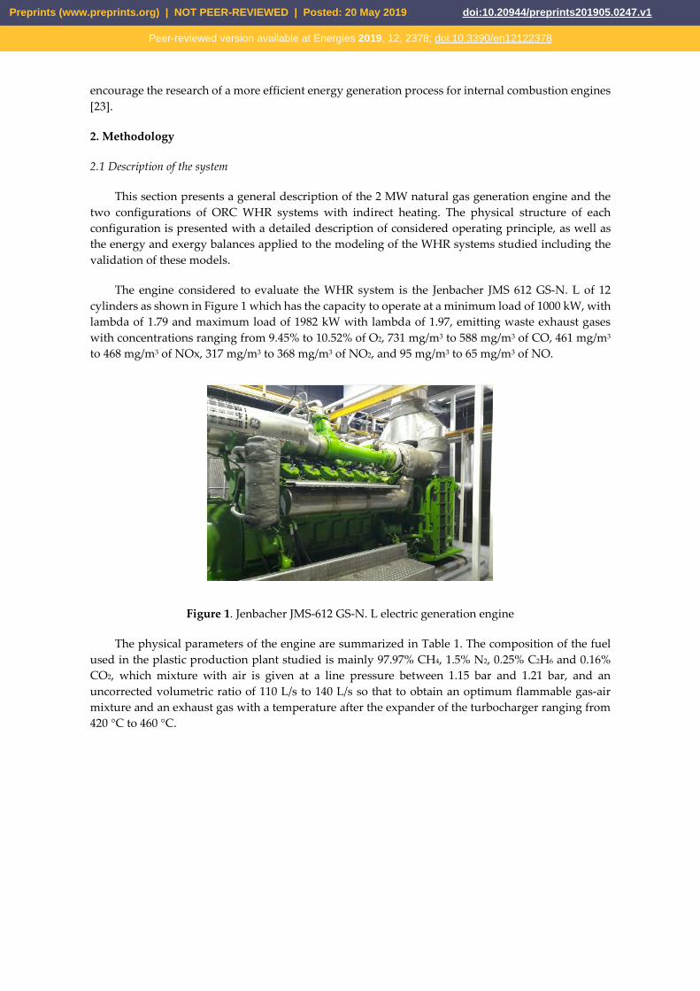
The engine considered to evaluate the WHR system is the Jenbacher JMS 612 GS-N. L of 12
cylinders as shown in Figure 1 which has the capacity to operate at a minimum load of 1000 kW, with
lambda of 1.79 and maximum load of 1982 kW with lambda of 1.97, emitting waste exhaust gases
with concentrations ranging from 9.45% to 10.52% of O2, 731 mg/m3 to 588 mg/m3 of CO, 461 mg/m3
to 468 mg/m3 of NOx, 317 mg/m3 to 368 mg/m3 of NO2, and 95 mg/m3 to 65 mg/m3 of NO.
Figure 1. Jenbacher JMS-612 GS-N. L electric generation engine
The physical parameters of the engine are summarized in Table 1. The composition of the fuel
used in the plastic production plant studied is mainly 97.97% CH4, 1.5% N2, 0.25% C2H6 and 0.16%
CO2, which mixture with air is given at a line pressure between 1.15 bar and 1.21 bar, and an
uncorrected volumetric ratio of 110 L/s to 140 L/s so that to obtain an optimum flammable gas-air
mixture and an exhaust gas with a temperature after the expander of the turbocharger ranging from
420 °C to 460 °C.
Preprints (www.preprints.org) | NOT PEER-REVIEWED | Posted: 20 May 2019 doi:10.20944/preprints201905.0247.v1
Peer-reviewed version available at Energies 2019, 12, 2378; doi:10.3390/en12122378

Table 1. Physical parameters of Jenbacher JMS 612 GS-N. L engine
Description Value Units
Cylinder capacity 74,852 𝐿
Compression ratio 10,5
Number of cylinders 12 𝐼𝑛 𝑉 60°
Stroke length 220 𝑚𝑚
Diameter in chamber 190 𝑚𝑚
Maximum torque 60,66 𝑘𝑁 × 𝑚
Maximum power 1820 𝑘𝑊@1500𝑟𝑝𝑚
Nominal speed 1500 𝑟𝑝𝑚
Ignition system Spark ignition
2.2 Description of the SORC, RORC, and DORC.
The configurations studied are presented in Figure 2 [24]. The physical structure for the SORC
is shown as in Figure 2a; this structure operates as follows: an air-natural gas mixture (stream 1) is
supplied to the ICE, which is compressed (stream 6) to mixing conditions prior to enter in the
combustion chamber. The exhaust gases at the outlet of the manifold (stream 9) expand in the
expansion stage of the turbocharger up to stream 10, which are evacuated to the environment (stream
11) after transferring the energy in the shell and tube heat exchanger (ITC 1), with the thermal oil
(stream 3 AT) that circulates through the secondary circuit of coupling employing the energy
supplied by Pump 1 (B 1). The hot thermal oil (stream 1 AT) serves as a thermal source to evaporate
the organic fluid to reach the superheated steam phase (1 ORC) at the high pressure and temperature
from the ORC to the turbine (T 1). The heat transfer process in ITC 2 is carried out in three zones
called preheating (Zone 1), evaporation (Zone 2) and superheating (Zone 3). As the organic fluid in
the turbine (T 1) from the evaporator (ITC 2) expands, an energy conversion process occurs in the
generator (G). The expansion of the fluid is given until the low pressure to enter the condenser (ITC
3), where all the mass is condensed until reaching the saturated liquid phase (stream 3 ORC). The
condensation process takes place in two stages that have been called condensation (stream 1 A –
stream 1g A) and cooling (stream 1g A – stream 2 A). Subsequently, in the pump (B 2), the fluid is
taken to the evaporating pressure in the ITC 2 exchanger, thus, completing the heat recovery system
through a SORC cycle.
The heat recovery system operating in the SORC configuration with heat exchanger shown in
Figure 2b consists of four heat exchange units: a shell and tube heat exchanger (ITC 1), an evaporator
(ITC 2), a condenser (ITC 3) and a heat recovery unit (RC), additionally the secondary circuit coupling
pump (B 1), the organic fluid pump (B 2) and a turbine (T 1). In this configuration, it is possible to
achieve an improvement in efficiency when the high-temperature organic fluid at the turbine outlet
(T 1) (1 ORC stream) preheats the organic fluid through the recuperator (RC) before reaching the
evaporator (ITC 2). The pump (B 2) transports the fluid to the high cycle pressure (5 ORC stream),
this is in order to be supplied to all components of the system. Subsequently, the organic fluid is
evaporated in the ITC 2 exchanger, which is composed by three zones, to complete the
thermodynamic cycle of power recovery [25], [26], [27].
The ORC cycle with two evaporating pressures shown in Figure 2c consists of two evaporators
(ITC 2 - ITC 4) and one condenser (ITC 3), two pumps (B 2-B 3), and two turbines (T 1 - T 2). During
this process, the organic fluid enters the second stage of the turbine (T 2) as superheated steam at
high pressure and temperature from the evaporator (ITC 4), where it expands to the intermediate
operating pressure of the pump (B 2). Consequently, the fluid enters the second stage in the turbine
Preprints (www.preprints.org) | NOT PEER-REVIEWED | Posted: 20 May 2019 doi:10.20944/preprints201905.0247.v1
Peer-reviewed version available at Energies 2019, 12, 2378; doi:10.3390/en12122378

(T 1) expanding to a mixture of the low operating pressure of the condenser, where the fluid cools
down to the liquid phase. Afterwards, the pump (B 2) discharges the intermediate pressure of the
cycle, so that a fraction of it evaporates in the ITC 2 exchanger and mixes with the current from the
T2 turbine, while the remaining fraction enters the B3 pump where it is taken to the high pressure of
the cycle to evaporate in the ITC 4 exchanger, finally completing the Rankine cycle of two evaporating
pressures. This configuration increases the efficiency of the cycle by decreasing the thermal load
dissipated to the environment [28].
Preprints (www.preprints.org) | NOT PEER-REVIEWED | Posted: 20 May 2019 doi:10.20944/preprints201905.0247.v1
Peer-reviewed version available at Energies 2019, 12, 2378; doi:10.3390/en12122378
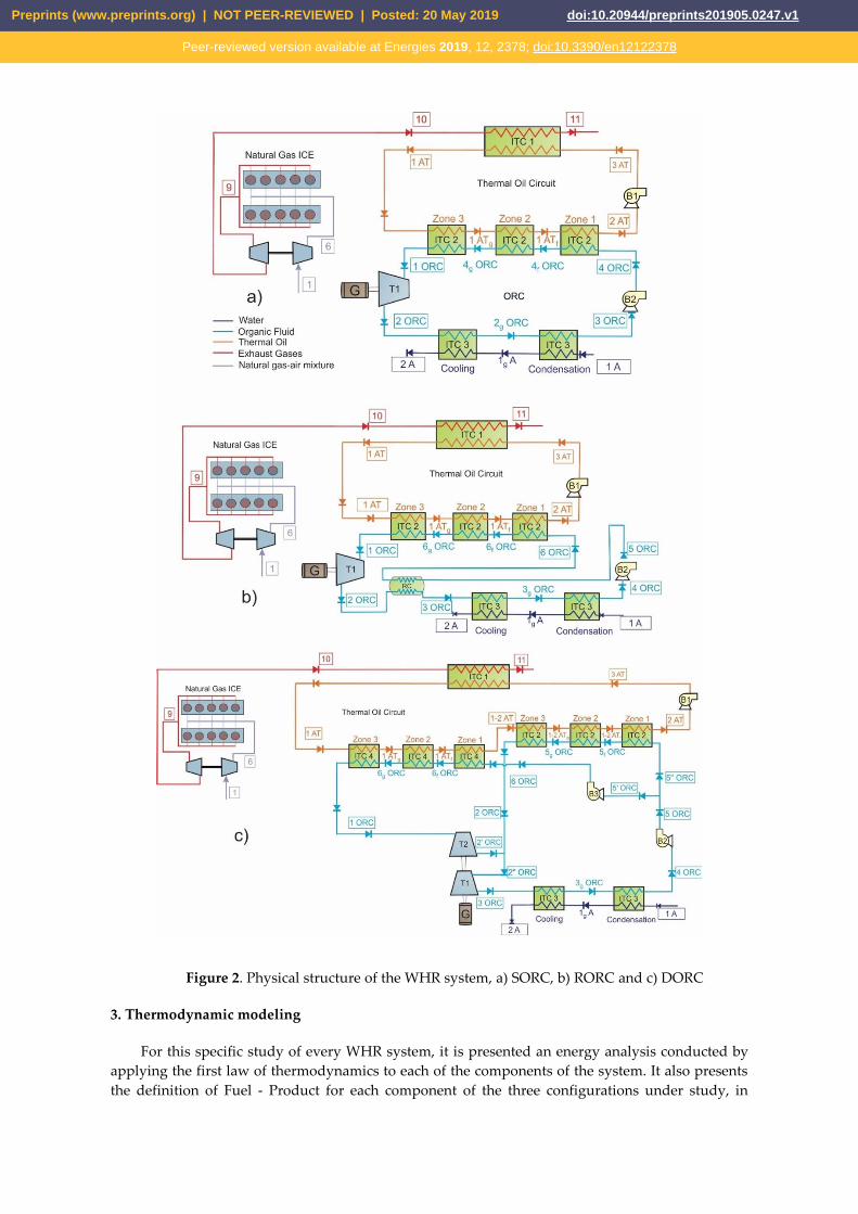
Figure 2. Physical structure of the WHR system, a) SORC, b) RORC and c) DORC
3. Thermodynamic modeling
For this specific study of every WHR system, it is presented an energy analysis conducted by
applying the first law of thermodynamics to each of the components of the system. It also presents
the definition of Fuel - Product for each component of the three configurations under study, in
Preprints (www.preprints.org) | NOT PEER-REVIEWED | Posted: 20 May 2019 doi:10.20944/preprints201905.0247.v1
Peer-reviewed version available at Energies 2019, 12, 2378; doi:10.3390/en12122378
addition to the performance indicators of each configuration through the first and second law of
thermodynamics.
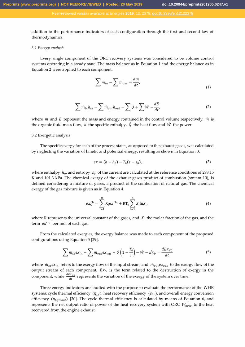
3.1 Energy analysis
Every single component of the ORC recovery systems was considered to be volume control
systems operating in a steady state. The mass balance as in Equation 1 and the energy balance as in
Equation 2 were applied to each component.
∑ ��𝑖𝑛 − ∑ ��𝑜𝑢𝑡 =𝑑𝑚
𝑑𝑡,
(1)
∑ ��𝑖𝑛ℎ𝑖𝑛 − ∑ ��𝑜𝑢𝑡ℎ𝑜𝑢𝑡 − ∑ �� + ∑ �� =𝑑𝐸
𝑑𝑡, (2)
where 𝑚 and 𝐸 represent the mass and energy contained in the control volume respectively, �� is
the organic fluid mass flow, ℎ the specific enthalpy, �� the heat flow and �� the power.
3.2 Exergetic analysis
The specific exergy for each of the process states, as opposed to the exhaust gases, was calculated
by neglecting the variation of kinetic and potential energy, resulting as shown in Equation 3.
𝑒𝑥 = (ℎ − ℎ0) − 𝑇0(𝑠 − 𝑠0), (3)
where enthalpy ℎ0, and entropy 𝑠0 of the current are calculated at the reference conditions of 298.15
K and 101.3 kPa. The chemical exergy of the exhaust gases product of combustion (stream 10), is
defined considering a mixture of gases, a product of the combustion of natural gas. The chemical
exergy of the gas mixture is given as in Equation 4.
𝑒𝑥Gch = ∑ Xie𝑥chi + RT0 ∑ 𝑋iln𝑋i
n
i=1
n
i=1
, (4)
where R represents the universal constant of the gases, and 𝑋i the molar fraction of the gas, and the
term exchi per mol of each gas.
From the calculated exergies, the exergy balance was made to each component of the proposed
configurations using Equation 5 [29].
∑ ��𝑖𝑛𝑒𝑥𝑖𝑛 − ∑ ��𝑜𝑢𝑡𝑒𝑥𝑜𝑢𝑡 + �� (1 −𝑇0
𝑇) − �� − 𝐸��𝐷 =
𝑑𝐸𝑥𝑉𝐶
𝑑𝑡 (5)
where ��𝑖𝑛𝑒𝑥𝑖𝑛 refers to the exergy flow of the input stream, and ��𝑜𝑢𝑡𝑒𝑥𝑜𝑢𝑡 to the exergy flow of the
output stream of each component, ��𝑥𝐷 is the term related to the destruction of exergy in the
component, while 𝑑𝐸𝑥𝑉𝐶
𝑑𝑡 represents the variation of the exergy of the system over time.
Three energy indicators are studied with the purpose to evaluate the performance of the WHR
systems: cycle thermal efficiency (𝜂𝐼,𝑐), heat recovery efficiency (𝜀ℎ𝑟), and overall energy conversion
efficiency (𝜂𝐼,𝑔𝑙𝑜𝑏𝑎𝑙) [30]. The cycle thermal efficiency is calculated by means of Equation 6, and
represents the net output ratio of power of the heat recovery system with ORC ��𝑛𝑒𝑡𝑜 to the heat
recovered from the engine exhaust.
Preprints (www.preprints.org) | NOT PEER-REVIEWED | Posted: 20 May 2019 doi:10.20944/preprints201905.0247.v1
Peer-reviewed version available at Energies 2019, 12, 2378; doi:10.3390/en12122378

𝜂𝐼, 𝐶 =��𝑛𝑒𝑡𝑜
𝑄��
. (6)
The heat recovery efficiency calculated through Equation 7, represents the amount of heat
recovered from the exhaust gases concerning their maximum thermal availability. Whereas the
overall energy conversion efficiency calculated as in Equation 8, relates the net output power to the
available heat in the exhaust gases.
𝜀ℎ𝑟 =𝑄��
��10𝐶𝑃10(𝑇10 − 𝑇0) (7)
𝜂𝐼,𝑜𝑣𝑒𝑟𝑎𝑙𝑙 = 𝜂𝐼, 𝐶 ∗ 𝜀ℎ𝑟 . (8)
Similarly, the absolute increase in thermal efficiency is calculated using Equation 9, which relates
the net power generated by the heat recovery system through an ORC configuration to the energy
provided by the fuel. This indicator determines the improvement in the performance of an ICE with
a given heat recovery system.
𝜂𝑡ℎ𝑒𝑟𝑚𝑖𝑐 =��𝑛𝑒𝑡𝑜
��𝑓𝑢𝑒𝑙 × 𝐿𝐻𝑉 (9)
Due to the additional power supply with the heat recovery system over the engine power, there
is a lower specific fuel consumption (BSFC) which is determined by Equation 10 [31].
𝐵𝑆𝐹𝐶𝑂𝑅𝐶−𝑒𝑛𝑔𝑖𝑛𝑒 =𝑚𝑓𝑢𝑒𝑙
��𝑒𝑛𝑔𝑖𝑛𝑒 + ��𝑛𝑒𝑡𝑜
. (10)
furthermore, the absolute decrease in specific fuel consumption is determined by Equation 11 and
represents a reduction in fuel consumption for particular operating conditions of the power
generation engine.
𝐵𝑆𝐹𝐶 =|𝐵𝑆𝐹𝐶𝑂𝑅𝐶−𝑒𝑛𝑔𝑖𝑛𝑒 − 𝐵𝑆𝐹𝐶𝑒𝑛𝑔𝑖𝑛𝑒|
𝐵𝑆𝐹𝐶𝑒𝑛𝑔𝑖𝑛𝑒
∗ 100. (11)
The exergy efficiency based on the second law of thermodynamics (𝜂𝐼𝐼,𝑂𝑅𝐶) is now calculated
as in Equation 12.
𝜂𝐼𝐼,𝑂𝑅𝐶 =E𝑥𝑝𝑟𝑜𝑑𝑢𝑐𝑒𝑑
E𝑥𝑠𝑢𝑝𝑝𝑙𝑖𝑒𝑑
, (12)
where E𝑥𝑠𝑢𝑝𝑝𝑙𝑖𝑒𝑑 is the amount of exergy supplied to the system, and E𝑥𝑝𝑟𝑜𝑑𝑢𝑐𝑒𝑑 the exergy
produced by the system. Exergetic efficiency can be expressed as a function of the destroyed exergy
E𝐷 through Equation 13.
𝜂𝐼𝐼,𝑂𝑅𝐶 = 1 −E𝑥𝐷
E𝑥𝑠𝑢𝑝𝑝𝑙𝑖𝑒𝑑
(13)
3.3 Exergy analysis
In order to construct a thermodynamic model for each configuration of the proposed recovery
systems, the following assumptions, that govern the phenomenology of the process and delimit the
scope of the results obtained, were considered:
- Pressure drops in pipes are neglected, whereas in heat exchange equipment the pressure drop is
considered as a function of the geometry and hydraulic characteristics of the flow.
Preprints (www.preprints.org) | NOT PEER-REVIEWED | Posted: 20 May 2019 doi:10.20944/preprints201905.0247.v1
Peer-reviewed version available at Energies 2019, 12, 2378; doi:10.3390/en12122378

- All the components of the cycle are thermally insulated.
- The variation in exhaust gas temperature is compensated by the thermal oil flow in the thermal
coupling cycle, ensuring that the ORC studied work under steady state conditions.
The energy and exergetic analysis of each of the three proposed ORC configurations were
developed in Matlab R2018b® [32], environment, calculating the thermodynamic properties in each
of the process states with the REFPROP 8.0® [33].
A specific operating condition of the Jenbacher JMS 612 GS-N L engine was selected so that it
can be possible to compare the results of the proposed configurations, whose operating parameters
considered for simulation are shown in Table 2. A particular operating condition of the process and
was selected for this study due to the fact that it contains representative values of the operation of
the system when it operates in an off-grid mode independent of the network.
Table 2. Parameters considered for ICE simulation
Parameter Value Units
Gas flow 120 𝐿/𝑚𝑖𝑛
Lambda 1,784
Rpm 1482 𝑟𝑒𝑣/𝑚𝑖𝑛
Gas pressure 1163,6 𝑚𝑏𝑎𝑟
Throttle valve 80 %
Turbo bypass valve 9,1 %
Gas temperature 389 °C
Engine coolant temperature 63,9 °C
The performance indicators of the engine in the selected base operating condition are shown in
Table 3, which are expected to be evaluated with each of the configurations.
Table 3. Performance indicators for ICE
Performance Indicators Value Units
Mechanical engine power 1758,77 𝑘𝑊
Effective engine efficiency 38,59 %
Heat recovery efficiency 40,78 %
Heat removed from exhaust gases 514,85 𝑘𝑊
Specific engine fuel consumption 177,65 𝑔/𝑘𝑊ℎ
The parameters considered for the study of WHR systems are shown as in
Preprints (www.preprints.org) | NOT PEER-REVIEWED | Posted: 20 May 2019 doi:10.20944/preprints201905.0247.v1
Peer-reviewed version available at Energies 2019, 12, 2378; doi:10.3390/en12122378

Table 4.
Preprints (www.preprints.org) | NOT PEER-REVIEWED | Posted: 20 May 2019 doi:10.20944/preprints201905.0247.v1
Peer-reviewed version available at Energies 2019, 12, 2378; doi:10.3390/en12122378

Table 4. Parameters considered for proposed configurations
The detailed equations of the energy balance applied to each component of the proposed
configurations are shown in Appendix A, Table A.13.
Accordingly, for each component can be differentiated an input, a product, a destroyed exergy value,
in some cases the exergy loss must be differentiated from the exergy destroyed [35]. The Input-output
structure for the components of the proposed WHR systems is shown as in Table 5.
Table 5. Fuel-Product definition for each configuration
Component
Different configurations of waste heat recovery systems using ORC
SORC RORC DORC
Fuel Product Lost Fuel Product Lost Fuel Product Lost
ITC1 ��𝑥10 ��𝑥1𝐴𝑇 - ��𝑥3𝐴𝑇
��𝑥11
��10 ��1𝐴𝑇-��3𝐴𝑇 ��11 ��𝑥10 ��𝑥1𝐴𝑇-��𝑥3𝐴𝑇 ��𝑥11
B1 ��𝐵1 ��𝑥3𝐴𝑇-��𝑥2𝐴𝑇 - ��𝐵1 ��𝑥3𝐴𝑇-��𝑥2𝐴𝑇 - ��𝐵1 ��𝑥3𝐴𝑇-��𝑥2𝐴𝑇 -
ITC2 ��𝑥1𝐴𝑇-��𝑥2𝐴𝑇 ��𝑥1𝑂𝑅𝐶- ��𝑥4𝑂𝑅𝐶 - ��𝑥1𝐴𝑇-��𝑥2𝐴𝑇 ��𝑥1𝑂𝑅𝐶-��𝑥6𝑂𝑅𝐶 - ��𝑥1−2𝐴𝑇- ��𝑥2𝐴𝑇 ��𝑥2𝑂𝑅𝐶-��𝑥5𝑂𝑅𝐶 -
T1 ��𝑥1𝑂𝑅𝐶-��𝑥2𝑂𝑅𝐶 ��𝑇1 - ��𝑥1𝑂𝑅𝐶- ��𝑥2𝑂𝑅𝐶 ��𝑇1 - ��𝑥2′′𝑂𝑅𝐶 - ��𝑥3 ��𝑇1 -
ITC3 - -
��2𝐴
- -
��2𝐴
- -
��2𝐴
B2 ��𝐵2 ��𝑥4𝑂𝑅𝐶- ��𝑥3𝑂𝑅𝐶 - ��𝐵2 ��𝑥5𝑂𝑅𝐶-��𝑥4𝑂𝑅𝐶 - ��𝐵2 ��𝑥5𝑂𝑅𝐶-��𝑥4𝑂𝑅𝐶 -
RC - - - ��𝑥2𝑂𝑅𝐶-��𝑥3𝑂𝑅𝐶 ��𝑥6𝑂𝑅𝐶-��𝑥5𝑂𝑅𝐶 -
- - -
T2 - - - - - - ��𝑥1𝑂𝑅𝐶-��𝑥2′𝑂𝑅𝐶 ��𝑇2 -
B3 - - - - - - ��𝐵3 ��𝑥6𝑂𝑅𝐶 -��𝑥5𝑂𝑅𝐶 -
ITC4 - - - - - - ��𝑥1𝐴𝑇-��𝑥1−2𝐴𝑇 ��𝑥1𝑂𝑅𝐶-��𝑥6𝑂𝑅𝐶 -
Configuration Parameter Value Units Reference
S / R / DP Isentropic efficiency turbines 80 % [34]
S / R / DP Isentropic efficiency pumps 75 % [34]
S / R / DP Cooling water temperature (T1A) 50 °C
S / R / DP Pinch Point condenser (ITC3) 15 °C
S / R Pressure Ratio B1 2,5
DP Pressure Ratio B1 11,09
S / R / DP Pinch Point evaporators (ITC2) (ITC4) 35 °C
R Recovery Effectiveness (RC) 85 % [34]
DP Pressure Ratio B2 20
DP Pressure Ratio B3 9
S / R Pressure Ratio B2 30
Preprints (www.preprints.org) | NOT PEER-REVIEWED | Posted: 20 May 2019 doi:10.20944/preprints201905.0247.v1
Peer-reviewed version available at Energies 2019, 12, 2378; doi:10.3390/en12122378

3.4 Validation
To validate the SORC configuration model, a comparative analysis was conducted with the
results of research performed by [36], [37]. The main parameters considered for both investigations
are shown in Table 6.
Table 6. Data used from the system for model validation
𝜼𝑩 𝜼𝑻 𝑻𝒇𝒖𝒆𝒏𝒕𝒆 [ºC] F [kg/s] 𝑻𝑪𝒐𝒏𝒅 [ºC] Pinch Point [ºC] 𝑷𝑽𝒂𝒑 [Mpa]
0,8 0,7 250 2,737 35 30 0,8-5,5
This model was validated considering two working fluids, R-11 and R-134a. Based on the
conditions reported in Table 6, the thermal efficiencies of the system were determined as a function
of the Turbine inlet pressure. The results of the behavior obtained for both fluids are shown in Figure
3.
Figure 3. Thermal efficiency of the ORC as a function of the turbine inlet pressure for a) Refrigerant
R-11, b) Refrigerant R-134a
The model proposed in this research evinces highly accurate proximity to the results obtained
for the same configuration proposed by Lacopo [15] and Huan Tian et al. [18]. In the range evaluated
when comparing with the results of Lacopo [15], the error does not exceed 3% for R-11, while for R-
134a it presents a maximum error of 6% for turbine inlet pressures less than 1 MPa, moreover, for
values greater than 2 MPa the error remains within the range of 3%. Furthermore, the proposed SORC
model, evaluated within the pressure range (2.5 MPa - 3 MPa), which is the operating range of the
current research, it can be observed that this relative error is under 1% with respect to that proposed
by Huan Tian et al. [18], which guarantees the validity of the model, hence the accuracy of the results.
In the case of the validation of the configuration model for a RORC, the results of this system
for a geothermal application were taken as references [38], [20]. The parameters considered for both
investigations are shown in
Preprints (www.preprints.org) | NOT PEER-REVIEWED | Posted: 20 May 2019 doi:10.20944/preprints201905.0247.v1
Peer-reviewed version available at Energies 2019, 12, 2378; doi:10.3390/en12122378

Table 7.
Preprints (www.preprints.org) | NOT PEER-REVIEWED | Posted: 20 May 2019 doi:10.20944/preprints201905.0247.v1
Peer-reviewed version available at Energies 2019, 12, 2378; doi:10.3390/en12122378

Table 7. Data used from the system for model validation.
𝜼𝑩 𝜼𝑻 𝑻𝒇𝒖𝒆𝒏𝒕𝒆 [ºC] F [kg/s] 𝑻𝑪𝒐𝒏𝒅 [ºC] Pinch Point [ºC] 𝑷𝑽𝒂𝒑 [Mpa]
0,95 0,89 165 84,36. 15 10 0,31
Several considerations were assumed to perform the comparative analysis of the RORC, such as,
the processes and subsystems were assumed in steady state, all devices were considered in adiabatic
conditions, the pressure drops in the ORC devices and in the pipes are neglected, in dead state the
reference temperature was 288 K. The comparison of the simulation results obtained in the model
proposed in this research with the results available in the literature are shown as in Table 8. As
observed for the three thermodynamic models, it exists a proper fit between the values of the
parameters calculated in this work and those previously published [38], [20]. Consequently, in the
case of isobutane as an organic working fluid, a percentage error between 0,73% and 0,62% for
thermal efficiency was obtained when compared with the work of R. S. El-Emam et al. and V. Zare
respectively. In the other hand, exergy efficiency percentage errors obtained were 0,18% and 0,35%
respectively, which allows this model to be used for the evaluation of this configuration operating as
a heat recovery system.
Table 8. Validation of the proposed model for RORC
Parameters Proposed
Model
R. S. El-Emam et al.
[38]
V. Zare
[20]
𝑇1 𝐴𝑇 (°𝐶) 165 165 165
��1 𝐴𝑇 (𝑘𝑔 𝑠⁄ ) 84,36 84,36 82,16
��1 𝑂𝑅𝐶 (𝑘𝑔 𝑠⁄ ) 75,22 78,06 76,09
𝐴𝐼𝑇𝐶 2 (𝑚2) 394,21 399,30 390,60
𝐴𝐼𝑇𝐶 3 (𝑚2) 809,52 810,10 808,70
𝐴𝑅𝐶 (𝑚2) 124,58 124,80 124,20
𝜂𝑡ℎ (%) 16,25 16,37 16,15
𝜂𝑒𝑥𝑒 (%) 48,71 48,80 48,54
4. Results and discussions
From the simulation results obtained, it is possible to determine and calculate the properties of
the main streams for the heat recovery system with single ORC, RORC, and DORC, the results are
shown in Appendix B Table B.14 B.1 for the case of SORC.
For each component of the system were applied mass and energy balances, the main results
obtained for the heat recovery system assembled with the engine are shown in
Preprints (www.preprints.org) | NOT PEER-REVIEWED | Posted: 20 May 2019 doi:10.20944/preprints201905.0247.v1
Peer-reviewed version available at Energies 2019, 12, 2378; doi:10.3390/en12122378

Table 9 respectively.
Preprints (www.preprints.org) | NOT PEER-REVIEWED | Posted: 20 May 2019 doi:10.20944/preprints201905.0247.v1
Peer-reviewed version available at Energies 2019, 12, 2378; doi:10.3390/en12122378

Table 9. Parameters of an integrated recovery system with engine and ORC
Parameters SORC RORC DORC. Units
Thermal efficiency engine-ORC 40,45 41,25 40,72 %
Increased thermal efficiency 1,86 2,66 2,13 %
Thermal efficiency ORC 16,40 23,51 18,74 %
Global energy conversion efficiency 6,68 9,59 7,66 %
Global exergetic efficiency 34,5 49,47 39,43 %
BSFC engine-ORC 169,5 166,21 168,42 g/kWh
An exergy balance was applied to each of the components of the system in order to calculate the
exergy for every stream, which results are presents as in Table 10 through the Input-Output definition
in every component of the SORC configuration.
Table 10. Exergy values for each component of the heat recovery system with SORC
Component Input (kW) Product (kW) ��𝒙𝑫(kW) Lost (kW)
ITC1 541,202051 202,794262 41,9535673 296,454222
B1 0,37472727 0,05848531 0,31624196
ITC2 202,852748 166,340104 36,5126437
T1 99,4808146 85,5899807 13,8908338
ITC3 36,0581887 66,5877282
B2 0,75619324 0,58683347 0,16935977
The fraction of exergy destroyed in each component of the cycle was calculated from the results
of the Input-output definition; the exergy destruction percentages are presented as in Figure 4a.
Figure 4. Exergy destruction by heat recovery system component a) SORC, b) RORC and c) DORC
It is observed that a large part of the exergy is destroyed in the tube and shell heat exchanger
(ITC1) with a value of 32,5%, followed by the evaporator with 28,3%, and condenser with 27,9%,
while the pumps in system present the lowest fractions of exergy destruction. Due to operational
restrictions on the temperature at the organic fluid to the turbine inlet, it is not possible to lower the
minimum temperature in the evaporator in order to obtain less entropy generated and thus less
Preprints (www.preprints.org) | NOT PEER-REVIEWED | Posted: 20 May 2019 doi:10.20944/preprints201905.0247.v1
Peer-reviewed version available at Energies 2019, 12, 2378; doi:10.3390/en12122378

exergy destroyed in this equipment. Nevertheless, these temperature differences in heat exchangers
must be optimized for better performance.
The use of isentropic and dry fluids in the RORC, allows obtaining relatively high temperatures
of the organic fluid at the exit of the turbine (2ORC stream) with superheated steam state [39], as is
the case of Toluene for this process as shown in Appendix B
Preprints (www.preprints.org) | NOT PEER-REVIEWED | Posted: 20 May 2019 doi:10.20944/preprints201905.0247.v1
Peer-reviewed version available at Energies 2019, 12, 2378; doi:10.3390/en12122378

Table B.2. Therefore, the internal heat exchanger (RC) absorbs the heat from the working fluid
leaving the turbine (T1) and increase the temperature of the fluid entering the evaporator (6ORC
stream) [40].
The heat transfers from the fluid at the turbine outlet to the fluid at the evaporator inlet that occurs
in the recuperator [41], allows an absolute increase the thermal efficiency of 2,6%, while in SORC
the increase presented was 1,8%. Consequently, the overall configuration presents a specific fuel
consumption of 166,21 g/kWh, 2% less than the SORC configuration as shown in
Preprints (www.preprints.org) | NOT PEER-REVIEWED | Posted: 20 May 2019 doi:10.20944/preprints201905.0247.v1
Peer-reviewed version available at Energies 2019, 12, 2378; doi:10.3390/en12122378

Table 9 for the same operating conditions with Toluene.
The efficiency and performance indicators of this configuration increase with the inclusion of
heat recovery system, due to it is possible, for an equal amount of heat entering the cycle, through
ITC1, to increase the power generation in the turbine. The improvement in efficiency varies according
to the working fluid and is directly related to its properties, primarily its specific heat [42]. The results
confirm that the recovery system has no effect on the power of the turbine and pump, however, it
directly influences the heat transfer in the evaporator and condenser [43], equipment where are the
highest irreversibility as shown in Table 11, obtaining exergy destruction values 33,82 kW (35,2%) in
the evaporator, followed by the recuperator with 21,86 kW (22,8%).
Table 11. Exergy values for each component of the heat recovery system with RORC
Component Input (kW) Product (kW) ��𝒙𝑫(kW) Lost (kW)
ITC1 541,202051 237,549898 7,197931 296,454222
B1 0,36222219 0,09598314 0,26623905
ITC2 237,645881 203,818309 33,827572
T1 139,797975 122,396844 17,40113113
ITC3 15,3197 71,5691491
B2 0,94533621 0,7336153 0,21172091
RC 86,4902041 64,620999 21,8692051
Furthermore, the fraction of exergy destroyed in each component of the cycle is presented in
Figure 4b, where the percentage contribution of the pumps only reaches 0.5% of the total exergy
destruction of the system.
For the DORC configuration there are two different evaporating pressures, however the 2 ORC,
2’ ORC and 2” ORC streams are mixed at the same pressure to perform work in the Turbine (T1).
Moreover, at the outlet of the low-pressure pump (B2) the states 5 ORC, 5’ ORC and 5” ORC have
similar thermodynamic properties with different mass flows as shown in Appendix B in Table B.3.
Preprints (www.preprints.org) | NOT PEER-REVIEWED | Posted: 20 May 2019 doi:10.20944/preprints201905.0247.v1
Peer-reviewed version available at Energies 2019, 12, 2378; doi:10.3390/en12122378

Table 9 presents the performance parameters of the integrated system with ICE and DORC, where it
is observed that this configuration in the evaluated conditions only achieves an overall energy
conversion efficiency of 6,68% and an overall exergetic efficiency of 34,37%. These results are directly
related to the pressure ratio values selected for this base case, according to state of the art, this
configuration presents a better exergy efficiency, and permits generating more power than the SORC
configuration and RORC [44].
In this configuration, the high-pressure evaporator (ITC 4) along together with the tube and shell heat
exchanger (ITC1) are the equipment where the highest exergy destruction levels are presented as in
Table 12 due to the temperature differences between the thermal oil and the organic fluid.
Table 12. Exergy values for each component of the heat recovery system with DORC
Component Input (kW) Product (kW) ��𝒙𝑫(kW) Lost (kW)
ITC1 541,20 203,57 31,15 296,45
B1 1,66 0,26 1,40
ITC2 113,18 101,93 11,26
T1 95,39 79,75 15,63
ITC3 31,01 6,00
B2 0,63 0,49 0,14
T2 10,27 8,77 1,49
B3 2,09 1,63 0,47
ITC4 90,64 52,66 37,99
The fraction of exergy destruction per component for the dual ORC heat recovery system is
shown as in Figure 4c, where evaporators and condensers contribute about 86,4% of the total
destroyed exergy. As the organic fluid evaporates in the heat exchangers at proper evaporating
pressure, a closer match can be maintained between the thermal oil cooling curve in the secondary
coupling circuit and the heating or boiling curve of the working fluid, consequently these losses can
be reduced.
4.1. Sensitivity analysis
4.1.1 Analysis of the influence of the evaporation pressure on the performance of the configurations.
Considering the relevance of the evaporation pressure on the operation of these systems, a
comparative analysis of the net power, an absolute increase of thermal efficiency and absolute
decrease of the specific consumption of fuel for the SORC, RORC, and DORC is presented in Figure
5. For the dual cycle, the values of high evaporation pressure were reached by varying the pressure
ratio of the B3 pump, with the pressure ratio values of the B2 pump fixed at 3 for Toluene, 10 for
Acetone and 1,5 for Cyclohexane.
It is observed that the power generated is directly related to the evaporation pressure, obtaining
for the evaluated conditions the most profitable results for the cycle with recovery efficiency of 80%
in the recuperator, operating with Toluene at an evaporation pressure of 3,4 MPa, with a maximum
power of 146,25 kW, which is equivalent to 31,9% more than the energy generated with the same
fluid as in the SORC at the same pressure. While varying the pressure ratio of the B3 pump in a dual
cycle is not possible to achieve the same evaporating pressure as the fluid is heated to the point of
reversing heat transfer in the evaporator with the thermal oil.
Preprints (www.preprints.org) | NOT PEER-REVIEWED | Posted: 20 May 2019 doi:10.20944/preprints201905.0247.v1
Peer-reviewed version available at Energies 2019, 12, 2378; doi:10.3390/en12122378
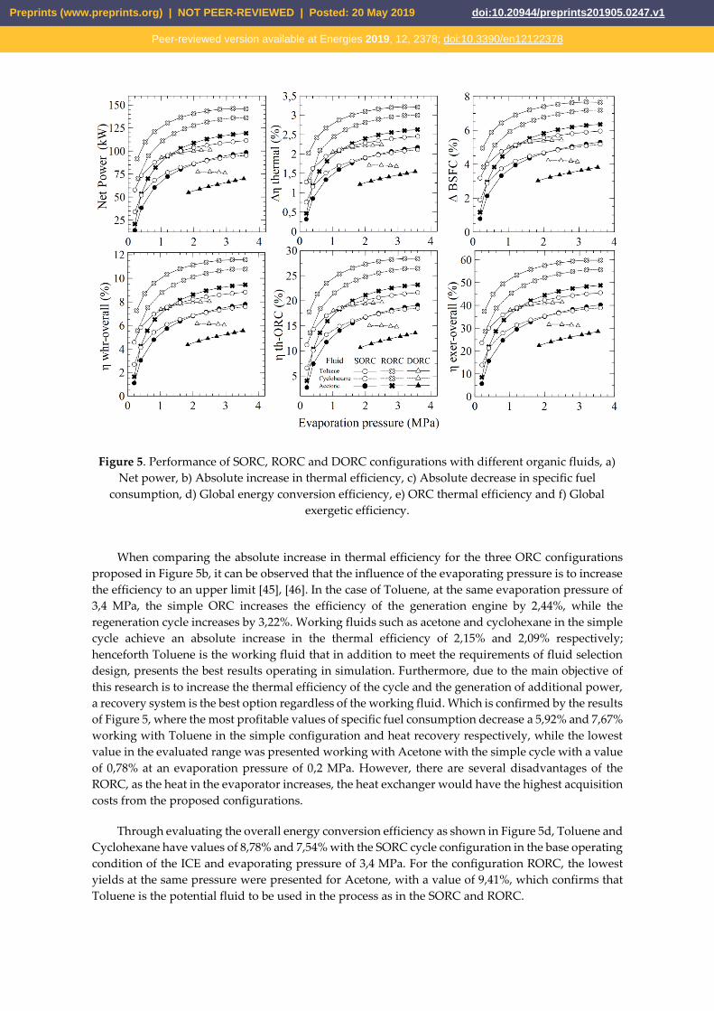
Figure 5. Performance of SORC, RORC and DORC configurations with different organic fluids, a)
Net power, b) Absolute increase in thermal efficiency, c) Absolute decrease in specific fuel
consumption, d) Global energy conversion efficiency, e) ORC thermal efficiency and f) Global
exergetic efficiency.
When comparing the absolute increase in thermal efficiency for the three ORC configurations
proposed in Figure 5b, it can be observed that the influence of the evaporating pressure is to increase
the efficiency to an upper limit [45], [46]. In the case of Toluene, at the same evaporation pressure of
3,4 MPa, the simple ORC increases the efficiency of the generation engine by 2,44%, while the
regeneration cycle increases by 3,22%. Working fluids such as acetone and cyclohexane in the simple
cycle achieve an absolute increase in the thermal efficiency of 2,15% and 2,09% respectively;
henceforth Toluene is the working fluid that in addition to meet the requirements of fluid selection
design, presents the best results operating in simulation. Furthermore, due to the main objective of
this research is to increase the thermal efficiency of the cycle and the generation of additional power,
a recovery system is the best option regardless of the working fluid. Which is confirmed by the results
of Figure 5, where the most profitable values of specific fuel consumption decrease a 5,92% and 7,67%
working with Toluene in the simple configuration and heat recovery respectively, while the lowest
value in the evaluated range was presented working with Acetone with the simple cycle with a value
of 0,78% at an evaporation pressure of 0,2 MPa. However, there are several disadvantages of the
RORC, as the heat in the evaporator increases, the heat exchanger would have the highest acquisition
costs from the proposed configurations.
Through evaluating the overall energy conversion efficiency as shown in Figure 5d, Toluene and
Cyclohexane have values of 8,78% and 7,54% with the SORC cycle configuration in the base operating
condition of the ICE and evaporating pressure of 3,4 MPa. For the configuration RORC, the lowest
yields at the same pressure were presented for Acetone, with a value of 9,41%, which confirms that
Toluene is the potential fluid to be used in the process as in the SORC and RORC.
Preprints (www.preprints.org) | NOT PEER-REVIEWED | Posted: 20 May 2019 doi:10.20944/preprints201905.0247.v1
Peer-reviewed version available at Energies 2019, 12, 2378; doi:10.3390/en12122378

The highest value for thermal efficiency of the ORC and global exergetic efficiency obtained were
obtained for the RORC, where the assembly of the recovery system to the evaporation pressure of 3,4
MPa, for the Toluene, increased the thermal efficiency from 21,53% to 28,41% and the global exergetic
efficiency from 45,29% to 59,76%, which confirms the excellent performance of Toluene at relatively
low pressures. The maximum power generated by the SORC configuration working with Toluene
seize approximately 8,31% of the generating capacity of the Jenbacher JMS 612 GS-N. L engine at
rated load speed. Additionally, it is observed that toluene in a SORC, increasing the evaporation
pressure from 2 MPa to 3 MPa, leads to a 5,49% increase in the power generated within a range from
103,61 kW to 109,3 kW. The absolute increase in thermal efficiency varies approximately 5,26% within
values from 2,28% to 2,40%. Finally, the absolute decrease in specific fuel consumption is higher by
5,21% given the increase presented from 5,56% to 5,85% respectively. On the other hand, in the case
of the cycle with recovery, the percentage increases for these variables were 3,76%, 3,75% and 3,47%,
which allows us to conclude that this variable is more influential in the SORC configuration.
4.4.2 Analysis of the influence of evaporation pressure on the destruction of exergy configurations
In order to perform a comparative analysis of the exergetic performance for each ORC
configuration, the fractions of exergy destruction in each component of the cycle were calculated with
the three proposed working fluids. The exergy destruction fractions for each ORC configuration are
shown as in Figure 6, at different evaporating pressures for Acetone, Cyclohexane, and Toluene.
The results demonstrate that the exergy fractions for the DORC cycle are higher than the SORC,
while the RORC cycle has the lowest values of total exergy loss.
Preprints (www.preprints.org) | NOT PEER-REVIEWED | Posted: 20 May 2019 doi:10.20944/preprints201905.0247.v1
Peer-reviewed version available at Energies 2019, 12, 2378; doi:10.3390/en12122378

Figure 6. exergy destruction by component as a function of evaporating pressure for (a, b and c)
configuration SORC, (d, e and f) configuration RORC and (g, h and i) configuration DORC
After the evaluation of the average decrease in percentage points of the three configurations
studied to the engine operating condition, it was demonstrated that the DORC cycle, working with
Toluene presents an average of 74,02% total exergy destruction, more significant than the exergy
destruction in RORC configuration. These results are due to the DORC configurations lead to higher
exergy destruction by having more components. However, in an operational range of evaporating
pressure, the dual ORC exceeds the destroyed exergy of the SORC by 9%. Consequently, the
evaporating pressure must be determined for each specific case to achieve the highest turbine output
power, and thus greater exergetic efficiency of the system.
The DORC configuration presents the highest values of exergy destruction fractions operating
with Acetone within the temperature range of the source studied, while the SORC configuration
presents the lowest values of exergy destruction fraction. As a result, the SORC configuration delivers
more power to the least heat rejection in the condenser; additionally, for the same power delivered,
this configuration requires less heat from the heat source. The results also show that the evaporating
Preprints (www.preprints.org) | NOT PEER-REVIEWED | Posted: 20 May 2019 doi:10.20944/preprints201905.0247.v1
Peer-reviewed version available at Energies 2019, 12, 2378; doi:10.3390/en12122378

pressure in the different ORC configurations has a significant effect on the total dimensionless exergy
losses, with a minimum value within the range studied.
The maximum values of exergy losses occurred in the condenser for every configuration, with a
maximum value of 88,26% for the SORC at 0,803 MPa. As a result, the exergy destruction fractions in
the condenser is inversely proportional to the evaporating pressure as it approaches 2 MPa. Due to
the significant increase in exergy losses, the evaporator and turbine cycle, in the RORC, the
recuperator acquires importance, while in the dual cycle the low evaporator provides exergy
destruction as the pressure increases.
4.1.3 Analysis of the influence of engine load on energy performance
This section analyzes the effect of engine load on the performance of the heat recovery system.
The results presented above were obtained based on the typical operating condition of a natural gas
engine. The engine power control system adjusts internal engine variables such as mixture pressure,
and temperature and mixture recirculation percentage to provide high efficiency in operations with
partial engine loads. The global energy indicators were selected as study variables, and the results of
the three configurations under study for an evaporating pressure of 675,8 kPa working with Toluene,
are shown as in Figure 7. For safety reasons, all possible operating points of the proposed
configurations at different engine loads, guarantee that Toluene vaporizes completely at the
evaporator outlet in order to prevent corrosion of the liquid in the expander. Moreover, the engine
exhaust gas temperature at the evaporator outlet (stream 11) must be higher than the acid spray
temperature (200 °C) to prevent acid corrosion of the exhaust.
The thermal efficiency presents a directly proportional relationship with respect to the engine
load increases, while the overall energy conversion efficiency presents an inversely proportional
relationship. The maximum net output power obtained for configurations at engine load percentages
is SORC (89,4 kW – 97,9%), RORC (124,5 kW – 97,9%) and DORC (86,29 kW – 91,81%). However, in
an engine operating interval, the thermal efficiency increase as the RORC configuration increases first
and then decreases, presenting a maximum performance with 82,68% engine load.
These results are due to the engine load is directly related to the flow in the exhaust gases and
the energy loss in the recuperator, since the evaporation pressure and the temperatures of the thermal
coupling oil have been restricted. As the operating load increases, there is an increase in the
evaporation temperature of the organic fluid. Therefore, the power increases, which is the main factor
that affects the thermal and exergetic efficiency. However, the isentropic efficiency of the turbine
decreases slightly as a consequence of the increase in the temperature of the thermal oil, causing a
decrease in the indicators at high engine loads. The direct relation between the net power and the
engine load is also due to the increase of the thermal oil inlet temperature to the evaporator, which
leads to an increase in the mass flow of Toluene, and the enthalpy difference between the pump and
the turbine, however, this causes a stronger effect in the turbine.
Preprints (www.preprints.org) | NOT PEER-REVIEWED | Posted: 20 May 2019 doi:10.20944/preprints201905.0247.v1
Peer-reviewed version available at Energies 2019, 12, 2378; doi:10.3390/en12122378

Figure 7. Performance of SORC, RORC and DORC configurations with different engine loads,
a) Net power, b) Absolute increase in thermal efficiency, c) Specific fuel consumption of engine -
ORC, d) Overall energy conversion efficiency, e) ORC thermal efficiency and f) Overall exergetic
efficiency.
5. Conclusions
The study allowed an energetic and exergetic analysis of three energy generation systems based
on ORC, to waste heat recovery from the exhaust gases of a generation engine using natural gas as
fuel in a plastic industry located in the Colombian Caribbean region. In particular, the results
obtained through a dynamic model validated with experimental data is used to know the exhaust
gases temperature, power output, fuel consumption and thermal efficiency of the gas engine based
on the mean variables of the system. The study involved the thermodynamic model development
and the research of energy and exergy performance indicator of the integrated engine system with
three configurations of waste heat recovery, to determine the improvement degree of the thermal
efficiency of the Jenbacher JMS 612 GS-N. L of 2 MW.
To propose a thermal system with a better performance, the irreversibilities and exergy
destruction of the components must be reduced. The destroyed exergy of all the elements in the
different configurations is low compared to the thermal oil pump (B1). These values suggest that
reducing the heat transfer area in the evaporator, recuperator, and condenser may provide a
favorable solution, especially in the DORC configuration. However, it is essential to note that these
plate heat exchangers are manufactured from specialized materials for these applications, which
contributes significantly to the total purchase cost of the systems. Also, the operation of this
equipment has a significant effect on the total exergy destruction and thermal efficiency of the system
as a result of the Pinch Point temperature. Therefore, increasing the size of heat exchangers increases
the cost of generating electricity.
Preprints (www.preprints.org) | NOT PEER-REVIEWED | Posted: 20 May 2019 doi:10.20944/preprints201905.0247.v1
Peer-reviewed version available at Energies 2019, 12, 2378; doi:10.3390/en12122378

The thermal oil pump is the equipment with the lowest efficiency from all the system
components, SORC (16%), RORC (26%) and DORC (17%). However, among the heat exchange
equipment, the shell and tube heat exchanger (ITC1) has the lowest exergetic efficiency in the three
configurations SORC (37%), RORC (44%) and DORC (38%), due to the organic fluid cannot reach the
engine exhaust gas temperature levels due to the increase of heat transfer irreversibilities and thermal
stability conditions. Hence, these alternatives present better results with medium and low quality
thermal sources of Exhaust gases.
The exergy destruction in ITC1 is the most important for the SORC and DORC applications,
while the evaporator (ITC2) is the most important for the RORC. Therefore, the effort should be
oriented to reducing the exergy destruction in these components. Based on commercial information
on the geometric characteristics of the plate heat exchangers and shell and tube heat exchanger, the
optimal sizes of these types of equipment for the different configurations should be determined.
Author Contributions: Conceptualization: G.V.; Methodology: G.V. and F.C.; Software: G.V., F.C.
and Y.C.; Validation: G.V., F.C. and Y.C.; Formal Analysis: G.V., J.D. and C.I.; Investigation: G.V.;
Resources: Y.C. and F.C.; Writing-Original Draft Preparation: G.V.; Writing-Review & Editing: J.D.
and C.I.; Funding Acquisition: G.V.
Funding: This work was supported by the Universidad del Atlántico, Universidad Pontificia
Bolivariana and the E2 Energía Eficiente S.A E.S. P company.
Conflicts of Interest: The authors declare no conflict of interest.
Abbreviations
The following abbreviations are used in this manuscript:
BSFC Brake Specific Fuel Consumption
DORC Double pressure Organic Rankine Cycle
GHG Green House Gases
GWP Global Warming Potential
ICE Internal Combustion Engine
ORC Organic Rankine Cycle
RORC Recuperator Organic Rankine Cycle
SORC Simple Organic Rankine Cycle
WHR Waste Heat Recovery
Nomenclature 𝐶𝑝 Specific heat at constant pressure (J kg⁄ K) 𝐸 Energy (J) 𝑒𝑥 Specific exergy (kJ 𝑘𝑔⁄ )
ℎ Specific enthalpy (kJ 𝑘𝑔⁄ )
𝐿𝐻𝑉 Heating power (kj kg⁄ )
𝑚 Mass (kg)
𝑄 Heat (J)
𝑅 Universal gas constant (atm L mol K⁄ )
𝑟𝑝𝑚 Engine speed (revolution per minutes)
𝑇 Temperature (K)
𝑡 Time (s)
�� Power (kW)
𝑋𝑖 Molar gas fraction
Greek Letters 𝜂𝐼,𝑐 Thermal efficiency of the cycle
𝜂𝐼,𝑔𝑙𝑜𝑏𝑎𝑙 Overall energy conversion efficiency 𝜂𝐼𝐼,𝑂𝑅𝐶 Exergetic efficiency
𝜀ℎ𝑟 Heat recovery efficiency
Preprints (www.preprints.org) | NOT PEER-REVIEWED | Posted: 20 May 2019 doi:10.20944/preprints201905.0247.v1
Peer-reviewed version available at Energies 2019, 12, 2378; doi:10.3390/en12122378

Subscripts 𝐷 Destroyed
G Gases
VC Control volume
Appendix A
The energy balance applied to each component of the proposed configurations is presented in
Table A.1.
Table A.13. Energy balances for the components of each configuration
Component Different configurations of residual heat recovery systems using ORC
SORC RORC DORC
Heat
Exchanger 1 (ITC1)
𝑄�� = ��10𝐶𝑃10(𝑇10 − 𝑇11)
= ��𝐴𝑇𝐶𝑃𝐴𝑇(𝑇4𝐴𝑇 − 𝑇3𝐴𝑇)
(A.1)
(A.1) (A.1)
Pump 1 (B1)
𝜂𝐵1 =𝜐2𝐴𝑇(𝑃3𝐴𝑇−𝑃2𝐴𝑇)
ℎ3𝐴𝑇−ℎ2𝐴𝑇
(A.2)
��𝐵1 = ��𝐴𝑇(ℎ3𝐴𝑇 − ℎ2𝐴𝑇)
(A.3)
(A.2) (A.2)
Heat
Exchanger (ITC2)
Zone 1 (Preheating)
��𝑍1 = ��𝐴𝑇(ℎ𝐴𝑇𝑓 − ℎ2𝐴𝑇)
= ��𝑂𝑅𝐶(ℎ4𝑓𝑂𝑅𝐶 − ℎ4𝑂𝑅𝐶)
(A.4)
Zone 2 (Evaporation)
��𝑍2 = ��𝐴𝑇(ℎ𝐴𝑇𝑔 − ℎ𝐴𝑇𝑓)
= ��𝑍2(ℎ𝑓𝑔𝑂𝑅𝐶)
(A.5)
Zone 3 (Overheating)
��𝑍3 = ��𝐴𝑇(ℎ1𝐴𝑇 − ℎ𝐴𝑇𝑔)
= ��𝑂𝑅𝐶(ℎ1𝑂𝑅𝐶 − ℎ4𝑔𝑂𝑅𝐶)
(A.6)
��𝑍1
= ��𝐴𝑇(ℎ𝐴𝑇𝑓 − ℎ2𝐴𝑇)
= ��𝑂𝑅𝐶(ℎ6𝑓𝑂𝑅𝐶 −
ℎ6𝑂𝑅𝐶) (A.13)
Zone 2 (A.5)
��𝑍3
= ��𝐴𝑇(ℎ1𝐴𝑇 − ℎ𝐴𝑇𝑔)
= ��𝑂𝑅𝐶(ℎ1𝑂𝑅𝐶 −
ℎ4𝑔𝑂𝑅𝐶) (A.14)
��𝑍1
= ��𝐴𝑇(ℎ𝐴𝑇𝑓 − ℎ2𝐴𝑇)
= ��𝑂𝑅𝐶(ℎ5𝑓𝑂𝑅𝐶 −
ℎ5𝑂𝑅𝐶) (A.21)
Zone 2 (A.5)
��𝑍3
= ��𝐴𝑇(ℎ1−2𝐴𝑇 − ℎ𝐴𝑇𝑔)
= ��5𝑂𝑅𝐶(ℎ2𝑂𝑅𝐶 −
ℎ5𝑔𝑂𝑅𝐶) (A.22)
Turbine 1 (T1)
𝜂𝑇1 =ℎ1𝑂𝑅𝐶−ℎ2𝑂𝑅𝐶
ℎ1𝑂𝑅𝐶−ℎ2𝑆𝑂𝑅𝐶
(A.7) ��𝑇1 =
��𝑂𝑅𝐶(ℎ1𝑂𝑅𝐶 − ℎ2𝑂𝑅𝐶)
(A.8)
(4A.7)
(4A.8)
𝜂𝑇1 =ℎ2′′𝑂𝑅𝐶−ℎ3𝑂𝑅𝐶
ℎ2′′𝑂𝑅𝐶−ℎ3𝑆𝑂𝑅𝐶
(A.29)
��𝑇1 = (��5𝑂𝑅𝐶 +
��6𝑂𝑅𝐶)(ℎ2′′𝑂𝑅𝐶 −
ℎ3𝑂𝑅𝐶)
(A.30)
Preprints (www.preprints.org) | NOT PEER-REVIEWED | Posted: 20 May 2019 doi:10.20944/preprints201905.0247.v1
Peer-reviewed version available at Energies 2019, 12, 2378; doi:10.3390/en12122378

Heat
Exchanger (ITC3)
Cooling ��𝑍𝐸 =
��𝑂𝑅𝐶(ℎ2𝑂𝑅𝐶 − ℎ2𝑔𝑂𝑅𝐶)
= ��1𝐴(ℎ2𝐴 − ℎ1𝑔𝐴)
(A.9)
Condenser
��𝑍𝐶
= ��𝑍𝐶(ℎ2𝑔𝑂𝑅𝐶 − ℎ3𝑂𝑅𝐶)
= ��1𝐴(ℎ1𝑔𝐴 − ℎ1𝐴)
(A.10)
��𝑍𝐸
= ��𝑂𝑅𝐶(ℎ3𝑂𝑅𝐶
− ℎ3𝑔𝑂𝑅𝐶)
= ��1𝐴(ℎ2𝐴 − ℎ1𝑔𝐴)
(A.15)
��𝑍𝐶
= ��𝑍𝐶(ℎ3𝑔𝑂𝑅𝐶
− ℎ4𝑂𝑅𝐶)
= ��1𝐴(ℎ1𝑔𝐴 − ℎ1𝐴)
(A.16)
(A.15)
(A.16)
Pump 2 (B2)
𝜂𝐵2 =𝜐3𝑂𝑅𝐶(𝑃4𝑂𝑅𝐶−𝑃3𝑂𝑅𝐶)
ℎ4𝑂𝑅𝐶−ℎ3𝑂𝑅𝐶
(A.11)
��𝐵2 = ��𝑂𝑅𝐶(ℎ4𝑂𝑅𝐶 −
ℎ3𝑂𝑅𝐶) (A.12)
𝜂𝐵2
=𝜐4𝑂𝑅𝐶(𝑃5𝑂𝑅𝐶 − 𝑃4𝑂𝑅𝐶)
ℎ5𝑂𝑅𝐶 − ℎ4𝑂𝑅𝐶
��𝐵2 =
��𝑂𝑅𝐶(ℎ5𝑂𝑅𝐶 − ℎ4𝑂𝑅𝐶)
(A.18)
𝜂𝐵2 =
𝜐4𝑂𝑅𝐶(𝑃5𝑂𝑅𝐶−𝑃4𝑂𝑅𝐶)
ℎ5𝑂𝑅𝐶−ℎ4𝑂𝑅𝐶
(A.27)
��𝐵2 = (��5𝑂𝑅𝐶 +
��6𝑂𝑅𝐶)(ℎ5𝑂𝑅𝐶 −
ℎ4𝑂𝑅𝐶)
(A.28)
RC
-
𝜀𝑅𝐶 =𝑇2𝑂𝑅𝐶−𝑇3𝑂𝑅𝐶
𝑇2𝑂𝑅𝐶−𝑇5𝑂𝑅𝐶
(A.19)
��𝑅𝐶
= ��𝑂𝑅𝐶(ℎ6𝑂𝑅𝐶
− ℎ5𝑂𝑅𝐶)
= ��𝑂𝑅𝐶(ℎ2𝑂𝑅𝐶 −
ℎ3𝑂𝑅𝐶) (A.20)
-
Turbine 2 (T2) - -
𝜂𝑇2 =ℎ1𝑂𝑅𝐶−ℎ2′𝑂𝑅𝐶
ℎ1𝑂𝑅𝐶−ℎ2′𝑆𝑂𝑅𝐶
(A.25)
��𝑇2 = ��6𝑂𝑅𝐶(ℎ1𝑂𝑅𝐶 −
ℎ2′𝑂𝑅𝐶) (A.26)
Pump 3 (B3) - -
𝜂𝐵3 =
𝜐5𝑂𝑅𝐶(𝑃6𝑂𝑅𝐶−𝑃5𝑂𝑅𝐶)
ℎ6𝑂𝑅𝐶−ℎ5𝑂𝑅𝐶
(A.31)
��𝐵3 = ��6𝑂𝑅𝐶(ℎ6𝑂𝑅𝐶 −
ℎ5𝑂𝑅𝐶) (A.32)
Preprints (www.preprints.org) | NOT PEER-REVIEWED | Posted: 20 May 2019 doi:10.20944/preprints201905.0247.v1
Peer-reviewed version available at Energies 2019, 12, 2378; doi:10.3390/en12122378

Heat
Exchanger (ITC4) - -
��𝑍1
= ��𝐴𝑇(ℎ𝐴𝑇𝑓 − ℎ1−2𝐴𝑇)
= ��6𝑂𝑅𝐶(ℎ6𝑓𝑂𝑅𝐶 −
ℎ6𝑂𝑅𝐶) (A.23)
Zone 2 (A.5)
��𝑍3
= ��𝐴𝑇(ℎ1𝐴𝑇 − ℎ1−𝐴𝑇𝑔)
= ��6𝑂𝑅𝐶(ℎ1𝑂𝑅𝐶 −
ℎ6𝑔𝑂𝑅𝐶) (A.24)
Appendix B
The properties of the main currents of the heat recovery system proposed with SORC are
presented in Table B.14.
Table B.14. Properties considered for SORC configuration
Stream Flow (kg/s) P. (kPa) T. (°C) Enthalpy
(kJ/kg)
Entropy(S-S0)
(kJ/kg K)
Exergy
(kW)
10 2,77 102,30 435,07 -1960,35 0,90 541,20
11 2,77 101,30 270,00 -2143,67 0,59 296,45
1 AT 1,64 101,43 307,84 461,66 0,94 208,75
1 ATg 1,64 91,42 246,29 324,52 0,73 106,76
1 ATf 1,64 81,01 178,30 183,24 0,47 29,12
2 AT 1,64 68,15 142,65 113,96 0,31 5,90
3 AT 1,64 170,38 142,77 114,19 0,31 5,96
1 ORC 0,72 675,85 272,84 633,29 1,80 169,27
2 ORC 0,72 22,53 202,37 513,72 1,87 69,79
2 gORC 0,72 22,53 65,00 301,64 1,34 31,18
3 ORC 0,72 22,53 65,00 -87,53 0,19 2,35
4 ORC 0,72 675,85 65,31 -86,47 0,19 2,93
4 fORC 0,72 675,85 194,20 181,72 0,86 50,17
4 gORC 0,72 675,85 194,20 477,95 1,50 124,68
1 A 13,32 101,30 50,00 209,42 0,27 35,20
1 gA 13,32 101,30 55,00 230,33 0,33 54,44
2 A 13,32 101,30 57,72 241,72 0,37 66,59
The properties of the main currents of the heat recovery system proposed with RORC are presented
in
Preprints (www.preprints.org) | NOT PEER-REVIEWED | Posted: 20 May 2019 doi:10.20944/preprints201905.0247.v1
Peer-reviewed version available at Energies 2019, 12, 2378; doi:10.3390/en12122378

Table B.2.
Preprints (www.preprints.org) | NOT PEER-REVIEWED | Posted: 20 May 2019 doi:10.20944/preprints201905.0247.v1
Peer-reviewed version available at Energies 2019, 12, 2378; doi:10.3390/en12122378

Table B.2. Properties considered for RORC configuration
Stream Flow (kg/s) P. (kPa) T. (°C) Enthalpy
(kJ/kg)
Entropy(S-S0)
(kJ/kg K)
Exergy
(kW)
10 2,77 102,30 435,07 -1960,35 0,90 541,20
11 2,77 101,30 270,00 -2143,67 0,59 296,45
1AT 1,51 101,43 374,47 618,96 1,25 263,92
1ATg 1,51 92,78 379,55 631,30 1,27 273,93
1ATf 1,51 83,89 294,56 431,40 0,98 126,19
2AT 1,51 68,15 209,28 246,22 0,65 26,27
3AT 1,51 170,38 209,40 246,46 0,65 26,37
1ORC 0,89 675,85 339,47 775,16 2,05 272,11
2ORC 0,89 22,53 268,70 638,39 2,11 132,31
3ORC 0,89 22,53 102,23 352,50 1,49 45,82
3gORC 0,89 22,53 65,00 301,64 1,34 38,98
4ORC 0,89 22,53 65,00 -87,53 0,19 2,93
5ORC 0,89 675,85 65,31 -86,47 0,19 3,67
6ORC 0,89 675,85 194,20 199,42 0,90 68,29
6fORC 0,89 675,85 194,20 181,72 0,86 62,72
6gORC 0,89 675,85 194,20 477,95 1,50 155,86
1A 16,65 101,30 50,00 209,42 0,27 44,00
1gA 16,65 101,30 55,00 230,33 0,33 68,06
2A 16,65 101,30 55,65 233,06 0,34 71,57
The properties of the main currents of the heat recovery system proposed with DORC are presented
in Table B.3.
Table B.3. Properties considered for DORC configuration
Stream Flow (kg/s) T. (°C) P. (kPa) Enthalpy
(kJ/kg)
Entropy (S-S0)
(kJ/kg K)
Exergy
(kW)
10 2,77 435,07 102,30 -1960,35 0,90 541,20
11 2,77 270,00 101,30 -2143,67 0,59 296,45
1 AT 1,62 316,58 686,83 481,81 0,99 215,40
1 ATg 1,62 296,48 676,43 435,75 0,92 178,88
1 ATf 1,62 245,76 666,37 323,37 0,74 99,29
1-2 AT 1,62 171,41 656,79 169,58 0,44 20,13
1-2 ATg 1,62 228,96 647,85 287,41 0,68 77,18
1-2 Atf 1,62 183,04 638,85 192,71 0,49 29,19
2 AT 1,62 150,98 630,14 129,89 0,35 7,53
3AT 1,62 151,51 755,78 130,91 0,35 7,80
1A 8,40 50,00 101,30 209,42 0,27 27,60
1g A 8,40 55,00 101,30 230,33 0,33 42,69
2A 8,40 55,00 101,30 234,54 0,34 46,10
1 ORC 0,45 281,58 1351,69 635,64 1,75 159,64
Preprints (www.preprints.org) | NOT PEER-REVIEWED | Posted: 20 May 2019 doi:10.20944/preprints201905.0247.v1
Peer-reviewed version available at Energies 2019, 12, 2378; doi:10.3390/en12122378
References
[1] Z. Mat Nawi, S. K. Kamarudin, S. R. Sheikh Abdullah, and S. S. Lam, “The potential of exhaust
waste heat recovery (WHR) from marine diesel engines via organic rankine cycle,” Energy,
vol. 166, no. 255, pp. 17–31, 2019.
[2] F. Alshammari, A. Pesyridis, A. Karvountzis-Kontakiotis, B. Franchetti, and Y. Pesmazoglou,
“Experimental study of a small scale organic Rankine cycle waste heat recovery system for a
heavy-duty diesel engine with focused on the radial inflow turbine expander performance,”
Appl. Energy, vol. 215, no. 122, pp. 543–555, 2018.
[3] P. Liu, G. Shu, H. Tian, X. Wang, and Z. Yu, “Alkanes based two-stage expansion with
interheating Organic Rankine cycle for multi-waste heat recovery of truck diesel engine,”
Energy, vol. 147, no. 866, pp. 337–350, 2018.
[4] C. N. Michos, S. Lion, I. Vlaskos, and R. Taccani, “Analysis of the backpressure effect of an
Organic Rankine Cycle (ORC) evaporator on the exhaust line of a turbocharged heavy duty
diesel power generator for marine applications,” Energy Convers. Manag., vol. 132, no. 25, pp.
347–360, 2017.
[5] P. S. Patel and E. F. Doyle, “Compounding the Truck Diesel Engine with an Organic Rankine-
Cycle System.” SAE International , 1976.
[6] B. Peris, J. Navarro-Esbrí, and F. Molés, “Bottoming organic Rankine cycle configurations to
increase Internal Combustion Engines power output from cooling water waste heat recovery,”
Appl. Therm. Eng., vol. 61, no. 2, pp. 364–371, 2013.
[7] G. Yu, G. Shu, H. Tian, H. Wei, and L. Liu, “Simulation and thermodynamic analysis of a
bottoming Organic Rankine Cycle (ORC) of diesel engine (DE),” Energy, vol. 51, no. 1–474, pp.
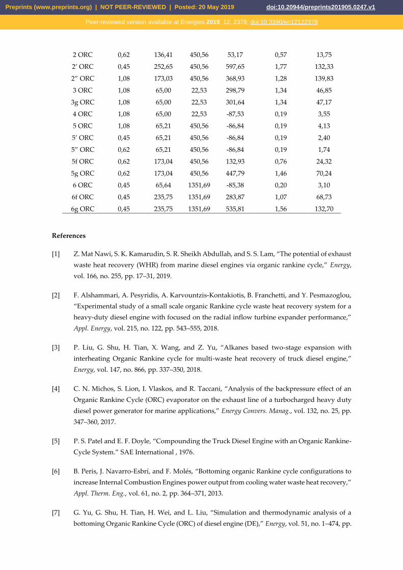
2 ORC 0,62 136,41 450,56 53,17 0,57 13,75
2’ ORC 0,45 252,65 450,56 597,65 1,77 132,33
2” ORC 1,08 173,03 450,56 368,93 1,28 139,83
3 ORC 1,08 65,00 22,53 298,79 1,34 46,85
3g ORC 1,08 65,00 22,53 301,64 1,34 47,17
4 ORC 1,08 65,00 22,53 -87,53 0,19 3,55
5 ORC 1,08 65,21 450,56 -86,84 0,19 4,13
5’ ORC 0,45 65,21 450,56 -86,84 0,19 2,40
5” ORC 0,62 65,21 450,56 -86,84 0,19 1,74
5f ORC 0,62 173,04 450,56 132,93 0,76 24,32
5g ORC 0,62 173,04 450,56 447,79 1,46 70,24
6 ORC 0,45 65,64 1351,69 -85,38 0,20 3,10
6f ORC 0,45 235,75 1351,69 283,87 1,07 68,73
6g ORC 0,45 235,75 1351,69 535,81 1,56 132,70
Preprints (www.preprints.org) | NOT PEER-REVIEWED | Posted: 20 May 2019 doi:10.20944/preprints201905.0247.v1
Peer-reviewed version available at Energies 2019, 12, 2378; doi:10.3390/en12122378

281–290, 2013.
[8] Y. Lu, Y. Wang, C. Dong, L. Wang, and A. P. Roskilly, “Design and assessment on a novel
integrated system for power and refrigeration using waste heat from a diesel engine,” Appl.
Therm. Eng., vol. 91, pp. 591–599, 2015.
[9] R. Chacartegui, D. Sánchez, J. M. Muñoz, and T. Sánchez, “Alternative ORC bottoming cycles
FOR combined cycle power plants,” Appl. Energy, vol. 86, no. 10, pp. 2162–2170, 2009.
[10] K. Qiu and A. C. S. Hayden, “Integrated thermoelectric and organic Rankine cycles for micro-
CHP systems,” Appl. Energy, vol. 97, no. 457–889, pp. 667–672, 2012.
[11] U. Drescher and D. Brüggemann, “Fluid selection for the Organic Rankine Cycle (ORC) in
biomass power and heat plants,” Appl. Therm. Eng., vol. 27, no. 1, pp. 223–228, 2007.
[12] P. J. Mago, L. M. Chamra, K. Srinivasan, and C. Somayaji, “An examination of regenerative
organic Rankine cycles using dry fluids,” Appl. Therm. Eng., vol. 28, no. 8, pp. 998–1007, 2008.
[13] G. Kosmadakis, D. Manolakos, S. Kyritsis, and G. Papadakis, “Comparative thermodynamic
study of refrigerants to select the best for use in the high-temperature stage of a two-stage
organic Rankine cycle for RO desalination,” Desalination, vol. 243, no. 1, pp. 74–94, 2009.
[14] B. F. Tchanche, G. Papadakis, G. Lambrinos, and A. Frangoudakis, “Fluid selection for a low-
temperature solar organic Rankine cycle,” Appl. Therm. Eng., vol. 29, no. 11–12, pp. 2468–2476,
2009.
[15] I. Vaja and A. Gambarotta, “Internal Combustion Engine (ICE) bottoming with Organic
Rankine Cycles (ORCs),” Energy, vol. 35, no. 2, pp. 1084–1093, 2010.
[16] J. Kalina, “Integrated biomass gasification combined cycle distributed generation plant with
a reciprocating gas engine and ORC,” Appl. Therm. Eng., vol. 31, no. 14, pp. 2829–2840, 2011.
[17] W. Mingshan, F. Jinli, M. Chaochen, and D. S. Noman, “Waste heat recovery from heavy-duty
diesel engine exhaust gases by medium temperature ORC system,” Sci. China Technol. Sci.,
vol. 54, no. 10, pp. 2746–2753, 2011.
[18] H. Tian, G. Shu, H. Wei, X. Liang, and L. Liu, “Fluids and parameters optimization for the
organic Rankine cycles (ORCs) used in exhaust heat recovery of Internal Combustion Engine
(ICE),” Energy, vol. 47, no. 1, pp. 125–136, 2012.
[19] T.-C. Hung, D.-S. Lee, and J.-R. Lin, “An Innovative application of a solar storage wall
combined with the low-temperature organic rankine cycle,” Int. J. Photoenergy, no. 239137, p.
12, 2014.
[20] V. Zare, “A comparative exergoeconomic analysis of different ORC configurations for binary
geothermal power plants,” Energy Convers. Manag., vol. 105, pp. 127–138, 2015.
Preprints (www.preprints.org) | NOT PEER-REVIEWED | Posted: 20 May 2019 doi:10.20944/preprints201905.0247.v1
Peer-reviewed version available at Energies 2019, 12, 2378; doi:10.3390/en12122378

[21] E. D. Kerme and J. Orfi, “Exergy-based thermodynamic analysis of solar driven organic
Rankine cycle,” J. Therm. Eng., vol. 1, no. 5, pp. 192–202, 2015.
[22] F. Calise, M. D. D’Accadia, A. Macaluso, A. Piacentino, and L. Vanoli, “Exergetic and
exergoeconomic analysis of a novel hybrid solar–geothermal polygeneration system
producing energy and water,” Energy Convers. Manag., vol. 115, no. 1–336, pp. 200–220, 2016.
[23] H. Jouhara and M. A. Sayegh, “Energy Efficient Thermal Systems and Processes,” Therm. Sci.
Eng. Prog., vol. 7, no. 125–130, pp. 1–5, 2018.
[24] A. Fontalvo, J. Solano, C. Pedraza, A. Bula, A. Gonzalez Quiroga, and R. Vasquez Padilla,
“Energy, Exergy and Economic Evaluation Comparison of Small-Scale Single and Dual
Pressure Organic Rankine Cycles Integrated with Low-Grade Heat Sources,” Entropy, vol. 19,
no. 10, p. 476, 2017.
[25] G. Li, “Organic Rankine cycle performance evaluation and thermoeconomic assessment with
various applications part I: Energy and exergy performance evaluation,” Renew. Sustain.
Energy Rev., vol. 53, pp. 477–499, 2016.
[26] G. Angelino, M. Gaia, and E. Macchi, “A review of Italian activity in the field of organic
Rankine cycles,” VDI. Ber., no. 539, pp. 465–482, 1984.
[27] B. Saleh, G. Koglbauer, M. Wendland, and J. Fischer, “Working fluids for low-temperature
organic Rankine cycles,” Energy, vol. 32, no. 7, pp. 1210–1221, 2007.
[28] T. Chen, W. Zhuge, Y. Zhang, and L. Zhang, “A novel cascade organic Rankine cycle (ORC)
system for waste heat recovery of truck diesel engines,” Energy Convers. Manag., vol. 138, pp.
210–223, 2017.
[29] M. J. Moran, H. N. Saphiro, D. D. Boettner, and M. B. Bailey, Fundamentals of Engineering
Thermodynamics. Wiley, 2011.
[30] S. Quoilin, R. Aumann, A. Grill, A. Schuster, V. Lemort, and H. Spliethoff, “Dynamic
modeling and optimal control strategy of waste heat recovery Organic Rankine Cycles,” Appl.
Energy, vol. 88, no. 6, pp. 2183–2190, 2011.
[31] E. Wang, Z. Yu, H. Zhang, and F. Yang, “A regenerative supercritical-subcritical dual-loop
organic Rankine cycle system for energy recovery from the waste heat of internal combustion
engines,” Appl. Energy, vol. 190, pp. 574–590, Mar. 2017.
[32] “‘Mathworks, «Matlab. Computer Program. MATLAB 2018b»’.”.
[33] M. O. Lemmon, E.W., Huber, M.L., McLinden, “NIST Standard Reference Database 23:
Reference Fluid Thermodynamic and Transport Properties (REFPROP) - Version 8.0,” Natl.
Inst. Stand. Technol. See https//www.techstreet.com/standards/nist-refprop-8-0?product_id=1696006,
2013.
Preprints (www.preprints.org) | NOT PEER-REVIEWED | Posted: 20 May 2019 doi:10.20944/preprints201905.0247.v1
Peer-reviewed version available at Energies 2019, 12, 2378; doi:10.3390/en12122378
[34] C. G. F. Val and S. O. Jr, “Deep Water Cooled ORC for Offshore Floating Oil Platform
Applications,” vol. 20, no. 4, pp. 229–237, 2017.
[35] A. B. Trindade et al., “Advanced exergy analysis and environmental assessment of the steam
cycle of an incineration system of municipal solid waste with energy recovery,” Energy
Convers. Manag., vol. 157, pp. 195–214, 2018.
[36] R. Scaccabarozzi, M. Tavano, C. M. Invernizzi, and E. Martelli, “Comparison of working fluids
and cycle optimization for heat recovery ORCs from large internal combustion engines,”
Energy, 2018.
[37] B. Kölsch and J. Radulovic, “Utilisation of diesel engine waste heat by Organic Rankine
Cycle,” Appl. Therm. Eng., vol. 78, pp. 437–448, 2015.
[38] R. S. El-emam and I. Dincer, “Exergy and exergoeconomic analyses and optimization of
geothermal organic Rankine cycle,” vol. 59, 2013.
[39] A. Uusitalo, J. Honkatukia, T. Turunen-Saaresti, and J. Larjola, “A thermodynamic analysis of
waste heat recovery from reciprocating engine power plants by means of Organic Rankine
Cycles,” Appl. Therm. Eng., vol. 70, no. 1, pp. 33–41, 2014.
[40] Y. Feng, Y. Zhang, B. Li, J. Yang, and Y. Shi, “Comparison between regenerative organic
Rankine cycle ( RORC ) and basic organic Rankine cycle ( BORC ) based on thermoeconomic
multi-objective optimization considering exergy efficiency and levelized energy cost ( LEC ),”
vol. 96, pp. 58–71, 2015.
[41] N. A. Lai, M. Wendland, and J. Fischer, “Working fluids for high-temperature organic
Rankine cycles,” Energy, vol. 36, no. 1, pp. 199–211, 2011.
[42] N. B. Desai and S. Bandyopadhyay, “Process integration of organic Rankine cycle,” Energy,
vol. 34, no. 10, pp. 1674–1686, 2009.
[43] R. Rayegan and Y. X. Tao, “A procedure to select working fluids for Solar Organic Rankine
Cycles ( ORCs ),” vol. 36, 2011.
[44] Z. Guzovi, “The comparison of a basic and a dual-pressure ORC ( Organic Rankine Cycle ):
Geothermal Power Plant Velika Ciglena case study,” vol. 76, no. 2014, 2015.
[45] V. Minea, “Power generation with ORC machines using low-grade waste heat or renewable
energy,” vol. 69, 2014.
[46] H. Nami, F. Mohammadkhani, and F. Ranjbar, “Utilization of waste heat from GTMHR for
hydrogen generation via a combination of organic Rankine cycles and PEM electrolysis,” vol.
127, pp. 589–598, 2016.
Preprints (www.preprints.org) | NOT PEER-REVIEWED | Posted: 20 May 2019 doi:10.20944/preprints201905.0247.v1
Peer-reviewed version available at Energies 2019, 12, 2378; doi:10.3390/en12122378