ENERCON - · PDF filemi ENERCON ENERCON E-70 E4 page "." ENERGY FORTHE WORLO...
17
.,.. ENERCON ENERCON E-70 E4 page "." ENERGY FOR THE WORLD Technical Description 1 of 17 Technical Description E-70 E4 Document Information: Translation Information Aulhor/dale: S. Anlas 121 .10.05 Department: VI Translaledldale: CCarsted 128.1105 Approvedldale: M.Kuhlmann 104.11.05 Revisedldale: Revision M.Heinemanni 002/ 0503 .07 Reference: VI-Technical Description E·70 E4_revOO2_ger- enadoc
Transcript of ENERCON - · PDF filemi ENERCON ENERCON E-70 E4 page "." ENERGY FORTHE WORLO...

.,.. ENERCON ENERCON E-70 E4 page
"." ENERGY FOR THE WORLD Technical Description 1 of 17
Technical Description
E-70 E4
Document Information: Translation InformationAulhor/dale: S. Anlas 121 .10.05Department: VI
Translaledldale: CCarsted 128.1105
Approvedldale: M.Kuhlmann 104 .11.05Revisedldale:
Revision M.Heinemanni 002/ 0503.07 Reference: VI-Technical Description E·70 E4_revOO2_ger-enadoc

;'i ENERCON ENERCON E-70 E4 page
l'til ENERGY FOR THE WORLD Technical Description 2 of 17
Table of Contents
1 Brief Description : 3
1.1 The ENERCON Concept .........•......•.......•......•............................................... ...•...•......•.........4
1.2 Rotor 6
1.3 Generator 6
1.4 Grid feed unit 7
1.5 Yaw control 9
1.6 Safety system 9
1.7 Control system 10
2 Control System 11
2.1 Response ta safety relevant sensor messages 11
2.2 Starting the turbine 11
2.3 Normal operation 11
2.4 Idle mode 12
2.5 Stopplng the turbine 12
2.6 Lack of wlnd 13
2.7 Storm 14
2.8 Yaw control ...................•.... ~ 14
3 Technical specifications: 16
ENERCON reserves the right la make any technical changes and improvemenls al any lime withoutprior notice.
Document Information: Translation InformationAulhor/date: s.Anlas /21 .10.05
Translatedldate: C.Carsted /28.1105Department: VIRevisedldate:Approvedldate: M.Kuhlmann / 04. t 1.05Reference: VI·Technical Description E-70 E4_revOO2_ger-
Revision M.Heinemanni 002/ 05.03.07ena.doc

mi ENERCON ENERCON E-70 E4 page
"." ENERGY FOR THE WORLO Techn~alDescripüon 3 of 17
1 BRIEF DESCRIPTION
The E-70 E4 is a wind energy converter with a three bladed rotor, active pitchcontrols, variable operating speed and a rated power of 2300 kW. Its 71 m rotordiameter and 64 - 113 m hub heights enable the turbine to make efficient use of theprevailing wind conditions at the respective sites to produce electrical energy.
-... ...., .......... .....-.----
I==.
Figure 1: Illustration E-70 E4
$',.
1 l '\
___=_==.=-l.::\~ =;7-=-==-__-
1
Document Information: Translatton InformationAuthor/date: S. Anlas 121 .10.05
Translatedldate: C.Carsted 128. t 1.05Departmenl: VI
Revisedldate:Approvedldale: M.Kuhlmann 104.11.05
Reference: VI-Technical Description E-70 E4_revOO2_ger-Revision M.Heinemanni 002/ 05.03 .07 eno.ooc

i'i ENERCON ENERCON E-70 E4 page
"." ENERGY FOR THE WORLD TechnicalDescripüon 4 of 17
The main objective of ENERCON design and engineering is to minimise loads. Aliturbine components are developed and constructed accordingJy. The result is aturbine which is, amongst other things, convincing due to its low Joad leveJ and longservice life.
Output controlled by variable speed allows the E-70 E4 to attain maximum operationefficiency without increasing operating Joads in the full and partial load ranges and atthe same time prevents undesirable output peaks thus guaranteeing excellent yieldand a high quality of power fed into the grid.
1.1 The ENERCON Concept
ENERCON wind energy converters are characterised by the following features:
The inner ring of the ENERCON annuJar generator and the rotor of the E-70 E4 formone unit. These two components are f1anged directly to the hub 50 that they bothrotate at the same low speed. Since there are no gears or other fast-rotating parts,energy loss between generator and rotor, noise emissions , the use of gear oil andmechanical wear are considerably reduced.
The output produced by the E-70 E4 generator is fed via the ENERCON gridconnection system into the power supply company's grid. The ENERCON gridconnection system comprises a rectifier/inverter unit (converter). This systemensures that high-quality electricity is fed into the power supply company's network.
Using the converter, this grid connection concept permits the E-70 E4's rotor tooperate at variable speeds. The rotor rotates slowJy at low wind speeds and quicklyat high wind speeds. This optimises wind flow on the rotor blades. Moreover,variable speed also reduces loads caused by gusts.
Each of the three rotor blades is equipped with an electrical pitch system. The pitchsystem limits the rotor speed and the use of the wind's power thus allowing theoutput of the E-70 E4 to be reduced to rated power, even within a short period. Bypitching the rotor blades into the feathered position, the rotor stops withoutmechanicaJ brakes exerting Joad on the drive train.
Document Infonnatlon: Translation InfonnatlonAuthor/date: S. Anlas 121 .1005
Translatedldate: C.Carsted 128.11 .05Department VIRevisedldate:
Approvedldate: M.Kuhlmann 104 .11.05Reference : VI-Technical Description E-70 E4_revOO2_ger-
Revision M.Heinemann! 002/ 05 .03.07ena.doc

.,. ENERCON ENERCON E-70 E4 page
_ ENERGY FOR THE WORLD Techn~alDescripffon 5 of 17
' ;'. :
. , " i"
f'-" " "
.~
:', ;- -: ,.s··
- -- ....
i:... -: ' ~ .
..... '.-
, ~. ~~.,;..:~~~: . .'-. -....-~~~ ;';" ~'. ; -'.-
. ~...... ... ..
. ,
. . :·=r
... . · ' 0
' . .
:-, '" ')..
, .
. -' . '
.:~ 'Main carrier ".
Ya~ n:t~tor~ ' ,
Il Ring generator .
Bladë adaptor
Rotor hùb .~ • J' . " ,
RotOr bl:~de " ' ". ... ..
..' .,\:. ,; "
Figure 2: illustration: Nacelle
Document Information: Translation InformationAuthor/date: S. Anlas/21 .10.05Department: VI Translatedldate: CCarsted / 28,1105
Approvedldate: M.Kuhlmann / 04.11.05 Revisedldate:
Revision MHeinemannl 002/ 05.03,07 Reference: VI-Technical Description E-70 E4_reIlO02_ger-enadoc

i'i ENERCON ENERCON E-70 E4 page
".., ENERGY FOR THE WORLD Technical Description 6 of 17
1.2 Rotor
The E-70 E-4 rotor blades made of glass reinforced plastic (GRP) (epoxy resin)have a major influence on turbine output and its noise emission. Their shape and.profile were developed according to the following criteria:
• high power coefficient
• long service Iife
• low noise emissions
• low loads and
• less material
One special feature to be pointed out is the new rotor blade profile which extendsdownto the nacelle. This innovative design eliminates the loss of the inner air flowexperienced with conventional rotor blades. Together with the streamlined nacelle,the use of prevailing winds is considerably optimised.
The rotor blades of the E-70 E4 were specially designed to operate with variablepitch control and variable speed. Due to this special profile, the blades are notsensitive to turbulence and dirt on the leading edge. On the outside, a top coatprotects the rotor blades against environmental factors. The polyurethane-basedmaterial employed is highly resistant. to abrasion, durable, and highly resistant tochemical factors and solar radiation.
Each of the three rotor blades is adjusted by independent microprocessor-controlledpitch systems. Angle encoders constantly monitor the set angle on each blade andensure that the three blades are synchronised. This permits quick and accurateadjustment according to the prevailing wind conditions.
1.3 Generator
The air flow on the rotor blades drives the rotor which in tum is the direct drive forthe E-70 E4 annular generator. The multipole ENERCON generator is based on thedirect drive synchronous machine principle.
Due to the low rotational speed and a large generator cross-section , temperaturelevels are comparatively low during operation and are only subject to minorfluctuations. Slight temperature fluctuations and comparatively few load changesduring operation significantly decrease mechanical stress and the associated wearon generator material and insulation. Furthermore, variable speed and theconnection to the electrical grid via converters contribute to reducing speed peaks.
Document Information: Translation InformationAulhor/date: S. Anlas 121 .1005
Translaledldale: C.Carsled 128 .11.05Department: VIRevisedldale:
Approvedldale: M.Kuhlmann 104.11.05Reference: VI-TechnicalDescription E-70 E4_revOO2_ger-
Revision M.Heinemann! 002/ 05.03.07eno .doc
~ENERCONENERCON E-70 E4 page
_ ENERGY FOR THE WORLD Technical Description 7 of 17
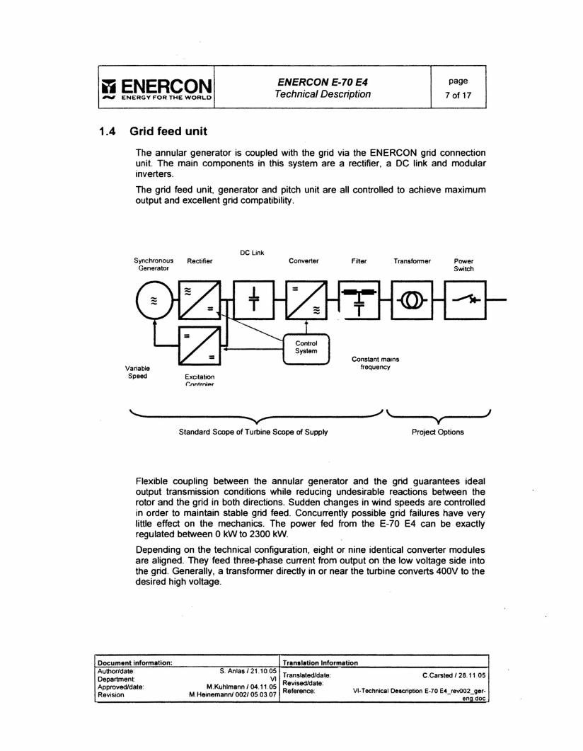
1.4 Grid feed unit
The annular generator is coupled with the grid via the ENERCON grid connectionunit. The main components in this system are a rectifier, a DC link and modularinverters.
The grid feed unit, generator and pitch unit are ail controlled to achieve maximumoutput and excellent grid compatibility.
DC LinkSynchronous Rectifier
GeneratorConverter Transfonner Power
Switch
VariableSpeed Excitation
(;n n trnlp r
Constant mainstrequency
J'---...._-------.... --------_/- "'-...._-- ----'-..",...- VStandard Scope of Turbine Scope of Supply Project Options
Flexible coupling between the annular generator and the grid guarantees idealoutput transmission conditions while reducing undesirable reactions between therotor and the grid in both directions. Sudden changes in wind speeds are controlledin order to maintain stable grid feed. Concurrently possible grid failures have veryIittle effect on the mechanics. The power fed from the E-70 E4 can be exactlyregulated between 0 kW to 2300 kW.
Depending on the technical configuration, eight or nine identical converter modulesare aligned. They feed three-phase current from output on the low voltage side intothe grid. Generally, a transformer directly in or near the turbine converts 400V to thedesired high voltage.
Document Inform ati on: Translation InformationAuthor/date: S. Anlas 121 .1005
Translated/date: C.Carsted 128 .11 .05Department: VI
Revisedldate :Approved/date: M.Kuhlmann 104.11.05
Reference: VI·Technical Description E·70 E4_rev002_ger.Revision M.Heinemann! 0021050307
eno.doc

liENERCON ENERCON E-70 E4 page
#ItrII ENERGY FOR THE WORLD Technical Description 8 of 17
With' this converter technology, the wind energy turbine can be considered as aregulated source of power As long as the voltage at the output terminais is within thepermissible range, the converters feed symmetrical, sinusoidal current. The voltageat the output is affected by the feed but it is not actively controlled. If desired, avoltage regulator can be installed at the wind farm's point of cornmon coupling.
Depending on the grid voltage phase angle and generator output, a target value forthe current to be fed is generated. Three-phase current is then generated accordingto this target value with the power available in the DC Iink. This target value iscompared to the actual current flow (actual value) every 100 IJsand corrected in theevent of deviations. The current fed is sinusoidal and largely free of disruptiveharmonie oscillations. A high frequency tilter further reduces harmonics. Nosigniticant flicker emissions occur. Momentary current peaks are excluded with thisconverter technology.
The range of operation parallel to the grid is Iimited by the minimum and maximumgrid voltage. Both these values (undervoltage and overvoltage) can be set as thelimit value for the E-70 E4.
Furthermore, ENERCON provides turbines as "transmission" versions on request.This means that the wind turbine can ride though voltage dips (grid failures) fromone to several seconds instead of immediately disconnecting from the grid. As soonas voltage is re-established maximum possible active power is fed into the grid.During a grid failure, active power is fed into the grid depending on the remainingvoltage, the maximum converter current and the actual wind conditions. In addition,the wind turbine can support the grid by feeding reactive current in the event of agrid failure. With this feature ENERCON wind turbines are able to provide windfarms with power plant properties often demanded and at the same time contributeto maintaining stable network operation.
The E70 E4 is preset to a power factor of cosq>=1. It does not require reactive powernor does it deliver reactive power to the grid within the entire power range trom 0 to2300 kW. Only active power is fed into the grid. Any equalization payments forreactive power demanded by sorne power supply network operators are notnecessary.
However, if requested by the power supply network operators, it is also possible torun the turbine with an output factor of t- 1. This enables the wind turbine tocontribute to reactive power balance and to maintain the voltage in the grid. Themaximum reactive power range varies depending on the turbine configuration. Theactive power being fed is not affected by reactive power being fed simultaneously.
The range of operation parallel to the grid is also determined by a lower and upperfrequency limit value. The range between these frequency limits is much wider thanin conventional energy production units thanks to ENERCON's flexible IGBTconverter technology. ENERCON wind turbines can be used in grids with a ratedfrequency of 50 Hz or 60 Hz.
If these voltage or frequency limits cannot be maintained, the E-70 E4 control unitswitches off ail grid contactors in the inverter. This allows the E-70 E4 toimmediately disconnect from the grid on ail phases.
Document Infonnatlon: Translation InfonnatlonAuthor/date: S. Anlas/21.10.05
Translatedldate: C.Carsted 128.1105Department VI
Revisedldate:Approved/date: M.Kuhlmann 104.11.05Reference: VI-TechnicalDescription E-70 E4_revOO2_ger-
Revision M.Heinemannl 002/ 05.03.07 ena.doc

~ENERCON ENERCON E-70 E4 page
"." ENERGY FOR THE WORLD Technical Description 9 of 17
1.5 Yaw control
The yaw bearing is mounted directly at the top of the tower with an extemally gearedring. The yaw bearing allows the nacelle to rotate, thus facilitating yaw control. Sixadjustment drives (yaw gears) engage in the geared ring in order to adjust thenacelle to the wind direction. The yaw bearing also transmits the load of the nacelleto the tower. The main carrier is mounted directly on the yaw bearing.
1.6 Safety system
The safety system guarantees safe turbine operation in accordance withinternational standards and independent test institutes.
1.6.1 Brake SystemHalting ENERCON turbine operation is done complete/y aerodynamically by pitchingthe rotor blades into the feathered position. The three independent pitch drivesmove the rotor blades into the feathered position within seconds (i.e. they are"driven out of the wind"). The speed of the turbine is diminished without applyingadditional load to the drive train. In order to reduce the rotor speed to a safe level, itwould be sufficient to drive only one of the three rotor blades out of the wind.
The rotor is not locked in place even when the WEC is shut down. It idles freely at avery low speed. The rotor and drive train remain practically without Ioad. Whileidling, fewer loads are placed on the bearings than when the rotor is locked.
The rotor is only completely locked in place for maintenance purposes or when theEMERGENCY STOP button is activated. In this case, an additional brake isemployed. It does not engage until the rotor has already been partially braked withthe pitch controls. The rotor lock is only used as a final safety mechanism formaintenance purposes.
ln the event of an emergency (e.g. if the utility's mains fails), each rotor blade issafely brought into the feathered position via its own back-up pitch unit. The backuppower units are monitored and automatically charged to guarantee availability. Thebackup pitch units, which are electromechanically Iinked, trigger simultaneous pitchcontrol.
The pitch control system is equipped with parallel power supply in the case ofemergencies (mains or backup power unit). Together with three fully independentpitch drives this safety concept more than fulfils the requirements for a fail safebraking system.
1.6.2 Lightning protection systemThe ENERCON lightning conductor system in the E-70 E4 efficiently diverts almostail possible lightning strikes with no damage caused to the turbine.
The leading and trailing edges of the rotor blade and the blade tip are equipped withaluminium profiles which are attached to an aluminium ring at the blade connectionpoint. Strikes are safely absorbed by these profiles and the lightning current isconducted via a spark gap and cables into the ground surrounding the foundation.
Document Information: Translation InformationAuthor/date: S. AIllas 121.1005
Translatedldate: C.Carsted 128.11.05Department: VIRevisedldate :
Approvedldate: M.Kuhlmann' 04.11.05 Reference: VI-Technical Desaiplion E·70 E4_revOO2_ger-Revision M.Heinemannl 002/ 05.03.07 enq.doc

iiENERCON ENERCON E-70 E4 page
l'til ENERGY FOR THE WORLD Technical Description 10 of 17
The rear of the nacelle casing is also fitted with a lightning conductor which divertsthe current into the ground.
ln the event of a lightning strike or an abnormal increase in voltage (overvoltage) ,the entire electrical andelectronic equipment is protected by built-in energyabsorbing components. Ali main conductive turbine components are connected tothe equipotential busbar with an adequate wire cross-section. Furthermore,overvoltage surge arresters are installed with low impedance grounding at the mainsconnection point.
The turbine electronics located in metal housing are electrically isolated. The remotemonitoring system is protected by a special protection module for data interfaces.
1.&.3 Sensor System
A comprehensive monitoring system guarantees turbine safety. Ali safety relatedfunctions (e.g. rotor speed, temperature. loads, oscillations) are monitored byelectronic media. If the electronics fail, a mechanical safety function takes over. Ifone of the sensors registers a serious fault, the turbine shuts down immediately.
1.7 Control system
The E-70 E4 control system is based on a microprocessor system developed byENERCON. Sensors query ail turbine components and data such as wind directionand wind speed and adjust the operating mode of the E-70 E4 accordingly .
VVhen wind speeds suitable for turbine operation are measured over threeconsecutive minutes, the automatic startup process is initiated. Once the lowerspeed range limit is reached, power output is fed to the grid. Elevated makingcurrent does not occur at start-up since the grid connection is performed through theOC Link and the converter.
During operation at partial load, speed and rotor blade angle are continuouslyadjusted to the changing wind conditions. Power is controlled through generatorexcitation. If rated wind speed is exceeded, the blade angle is adjusted to maintainrated speed.
VVhen the storm control system (optional) is deactivated, the turbine stops as saonas an average wind speed of 25 mis in the 10-mnute-mean or a peak value of 30mis is exceeded. The turbine restarts when the wind speed constantly remainsbelow the shutdown wind speed. The rotor is permitted to idle freely at a very lowspeed even in the shutdown mode.
Yaw control begins even before the start-up speed has been reached. The windvane constantly takes wind direction rneasurements. If the deviation between thedirection of the rotor axis and the rneasured wind direction is too great. the yawadjustrnent drives correct the nacelle position. The deviation angle and the time ittakes for the nacelle position to be corrected vary depending on the wind speed.
VVhether the turbine is stopped rnanually or via the turbine controls, the blade ispitched into the feathered position to reduce the actual contact surface of the windflow on the blade. The turbine gradually slows down to idle mode.
Document Informatlon: Translatton InformationAuthor/date: S.Anlas/21 .10.05
Translatedlda1e: C.Carsted / 28.11.05Oepartment VI
Revisedldate:ApprovedJdate: M.Kuhlmann / 04.11.05Reference: VI-TechnicalDescription e-7o e4_rey()()2_ger-
Revision M.Heinemann/ 002/ 05.03.07ena.doc

ijENERCON ENERCON E-70 E4 page
#tri ENERGY f'OR THE WORLD Technical Description 11 of 17
2 CONTROLSVSTEM
2.1 Response to safety relevant sensor messages
Turbine response to messages received trom individual sensors is explained in thefollowing sections. If a safety relevant sensor responds, the turbine initiates anautomatic shutdown. The nature of the shutdown and whether it is followed by arestart depends on the fault in question.
Turbine fault occurrences are displayed on the LCD. Minor faults can be reset bypressing the "Acknowledge fault" button once their cause has been established.Afterwards, the turbine automatically starts up again. Some faults may only berectified by Service technicians and then deleted. The respective status text flasheson the LCD. These messages are also marked with an asterisk.
Furthermore, sensor reliability is constantly monitored by the control system. If thesensors respond, a fault message is sent via the remote monitoring system.Depending on the sensor, the turbine may continue to operate for a certain amountof time. If certain sensors respond, the turbine has to be stopped immediately andthe fault rectified.
2.2 Starting the turbine
Unless expressly stated otherwise, these instructions apply to startup after anautomatic shutdown and for operation start up with the starUstopswitch.
VVhen the turbine is switched on (main switch on control cabinet to "ON" andstarUstop switch is set to start}, "Turbine operational" appearson the LCD shortlyafterwards (status O:2), provided the E-70 E4 control system has not detected anyfaults. Ninety seconds after start-up, the rotor blades are driven out of the featheredposition (approx. 90°) and "idle mode" begins. The rotor starts tuming slowly. Theturbine begins the actual operations startup procedure when the average windspeed is greater than the required startup wind speed for three consecutive minutes.
2.3 Normal operation
Once the E-70 E4 startup procedure is completed, the wind energy converterswitches to normal operation. During operation, the wind conditions are continuouslydetermined: rotor speed, generator excitation and output are optimised, the nacelleposition is adjusted to the wind direction and ail sensor messages are recorded.VVhen outside temperatures are high and if the wind speeds are also elevated, thegenerator fan is switched on. .
2.3.1 Operation at partial loadDuring operation at partial load, the speed and power output are continuouslyadjusted to the changing wind conditions. In the upper partial load range, the rotorblades are pitched a few degrees to avoid flow interruption (stail effect).
As wind speed increases, the rotor speed and power output increase.
Document Information: Translation InformationAuthor/date: S. Anlas 121 .10.05
Translatedldate: C.Carsted 128 .1105Department: VI
Revisedldate:Approved/date: M.Kuhlmann 104.11.05
Reference: VI-Technical Description E-70 E4_revOO2_ger-Revision M.Heinemann! 0021 05 .03.07 enq.doc
~ENERCONENERCON E-70 E4 page
l'tri I!:N~GY ,.OR THE WORLD Technical Description 12of 17
2.3.2 Automatlc control mode\Nhen the wind speed exceeds the rated wind speed, the blade angle is adjusted tomaintain the rotor speed at 1 or around its rated value and to Iimit the use of thewind's power ("automatic control mode"). The required blade angle adjustment isdetermined by evaluating speed and acceleration measurement data which is thentransmitted to the pitch drives. This maintains power output at its rated value.
2.4 Idle mode
If the turbine is shut down (e.g. due to lack of wind or faults), the rotor blades arenormally positioned at a 60° angle in relation to the operating position. The turbinethen rotates at a slow speed. If this speed (approx. 3 U/min) is exceeded the rotorblades are pitchedturther into the feathered position (approx. 90°). This operatingmodeis called "idling". Idling reduces load and enables the turbine to be restarted inthe shortest possible time. The reason for turbine shutdown or idle mode is indicatedby the status message.
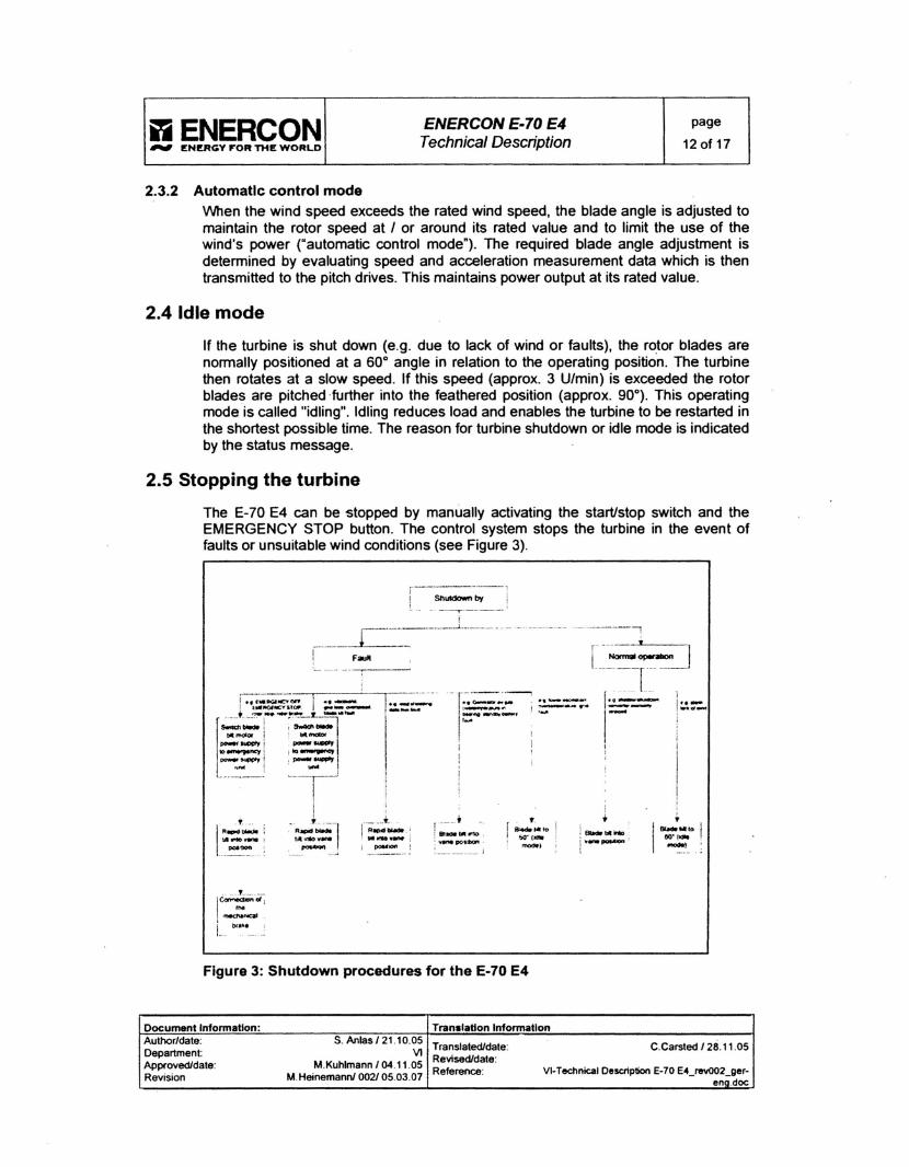
2.5 Stopping the turbine
The E-70 E4 can be stopped by rnanually activating the startlstop switch and theEMERGENCY STOP button. The control system stops the turbine in the event offau/ts or unsuitable wind conditions (see Figure 3).
-~ ....._ ._---,•• r--_... .......~==:-..;:-, ! -::;--- ....,...
r---'-'~~- '
! ~=-~__ii
_____ __~-----~~-------l------ - - .
1 F_
------,
,-:... ..~.
[-p_J• 11·<1 .......- l'....,==- ---1,,
•!Bla*bII" :
i'- - 'r ~~fo, W(1'JIit. ...-.
1 __ ... fl Bl acle' ''' ~ ,: .,.".~;tIQn.
, ~ ~ _•.• __,, ~ . ,,~ .•,. J
. t ..1"- - ';; ......... ~
i pooMic:Ift !
. L oo _
I~d ,
,- 'L. bf~~.._. . ..;
Figure 3: Shutdown procedures for the E-70 E4
Document Information: Translation InformationAuthor/date: S. Anlas /21.10.05
Translatedldate: C.Carsted /28.11.05Department: VI
Revisedldate:Approvedldate: M.Kuhlmann / 04.11.05
Reference: VI-Technical Description E-70 E4_revOO2_ger-Revision M.Heinemann! 002/ 05.03.07 ena .doc

.,ENERCON ENERCON E-70 E4 page
*"" ENERGY FOR THE WORLD Technical Description 13 of 17
2.5.1 Automatic shutdown
ln automatic mode, ENERCON wind energy converters are only brought to astandstill aerodynamically by pitching the rotor blades. Pitching the rotor bladesreduces the aerodynamic lift force which slows the rotor down. The pitch controldevices can drive the rotor blades out of the wind (Le. into the feathered position)within seconds.
. The turbine also stops automatically when certain faults or operating events occur orunder certain wind conditions. Some faults cause rapid shutdown to occur. Thishappens via the rotor blades' backup power units. Other faults result in a normalshutdown.
Automatic restart may be possible depending on the type of fault. In each case theconverters are electrically isolated from the grid during shutdown.
2.5.2 Manual stop
The E-70 E4 can be stopped via the start/stop switch on the control cabinet. Thecontrol system then pitches the rotor blades out of the wind and the turbine slows toa hall The brake is not activated and yaw control remains in operation so that the E70 E4 can continue to optimally adjust to the wind.
2.5.3 Manual shutdown in emergency situationsIf individuals or turbine parts are at risk, the turbine can be stopped by pressing theEMERGENCY STOP button. An EMERGENCY STOP button is located on thecontrol cabinet. Pressing it will induce immediate emergency braking on the rotorwith rapid pitch control via the emergency pitch and brake units. At the same timethe mechanical brakes are activated. Ali components continue to be supplied withpower.
The buttons are latched and have to be pulied back to their original position oncethe emergency has passed and the turbine is to be restarted.
If the main switch on the control cabinet is set to the OFF position, ail turbinecomponents, except for tower and control cabinet lighting and individual lightswitches and seckets, are switched off. The turbine activates rapid pitch control viathe emergency pitch devices. The mechanical brake is not activated when the mainswitch is used.
2.6 Lack of wind
If the turbine is in operation and the rotor speed drops too low due to lack of wind,the turbine is switched to idle mode by slowly pitching the rotor blades towards the60° angle. The turbine then restarts automatically when the eut-in wind speed isreached.
If the anemometer freezes due to low temperatures «3°C), the turbine attempts tostart at hourly intervals to test whether the wind speed is sufficient for operationwhen the wind vane is functioning. If the turbine starts and produces power, it goesinto normal operation. However, the correct wind speed does not appear on thedisplay since the frozen senser cannot provide accurate wind speed data.
Document Information: Translation InformationAuthor/date: S. Anlas /21.10.05
Translaledldale: c .carsted /28.11.05Departrnent: VIRevisedldale:
Approvedldale: M.Kuhlmann / 04.11.05Reference: VI-TechnicalDeSCliplion E-70E4JevOO2_ger-
Revision M,Heinemannl 002/ 05.03.07 eno.doc

l'ii ENERCON ENERCON E-70 E4 page
,.", ENERGY FOR THE WORLD Technical Description 14 of 17
2.7 Storm
From the standstill position or idle mode the turbine does not start up at wind speedsover 25 mis. If an average wind speed of 25 mis or a top value of 30 mis isexceeded, the E-70 E4 automatic control mode stops. The turbine also stops if themaximum permissible blade angle is exceeded. A frozen anemometer thereforedoes not represent a safety risk. In ail cases the turbine switches to idle mode.
The E-70 E4 components, such as rotor blades, nacelle, tower and foundations aredesigned to withstand considerably higher wind speeds.
The turbine starts automatically if the wind speed drops below eut-out wind speed(25 mis) for 10 consecutive minutes.
When wind speeds surpass 28 mis the ENERCON Storm Control System does notshut down the turbine abruptly, but rather reduces the power by continuouslypitching the rotor blades. The output is only reduced to zero at wind speeds ofapprox. 34°mls. This strategy improves electrical behaviour in the grid at the sametime increases output.
2.8 Yaw control
The E-70 E4 has a combination wind sensor, which is installed on the top of thenacelle. The combined wind sensor comprises a wind vane, which constantlydetermines the wind direction, and an anemometer, which measures wind speed.
E-70 E4 yaw control already starts to operate below the cut-in wind speed of 2 mis .Even if the system shuts down (e.g. due to excessive wind speed), it adjustsaccording to the wind conditions. The angle and the period of measurement dependon the wind speed and turbine performance.
1--1
mcnlh.-. 31eft 2 · 3 r.ftbns_..-
~and"'" 2 -3ng11l .... men lfWt J rigtIt......- ..- _to_ _to_..- ........-
dirK:lclnmcntNn. <lt"edIon,......twt.CM'teIrIITfriIn.In~
_.-.un.....I ~~·~II ~ 1--:-1 [:$J'.... (v < 3.5 nnl
11
11 1
EJ I ~.;:- I fr~ [§]St.na22: 1 .... 1 _ 2221
Figure 4: illustration of yaw control
Document Information: Translation InformationAuthor/date: S. Anlas/21 .10.05
Trans/aled/dale: C.Carsted /28.11.05Oepartmen l: VI
Revisedldate :Approvedldale: M.Kuhlmann / 04.11.05
Reference: VI-TechnicalOescription E-70 E"_revOO2_ger-Revision M.Heinemann! 002/ 05.0307 ena.doc
iiENERCON ENERCON E-70 E4 page
l1'fII ENERGY FOR THE WORLD Techn~a'Description 15 of 17
Yaw procedure is determined by counting the pitch motor rotations and the requiredpitch time is checked for plausibility . If the control system detects irregularities inyaw control or cable untwisting (See following), shutdown procedure is initiated.
2.8.1 Untwistlng power and control cables
The E-70 E4 power and control cables located in the tower pass tram the nacelleover a deflection pad and are then fastened to the tower wall. The cables haveenough freedom of movement to permit the nacelle to rotate several times in thesame direction about its axis. The cables gradually twist. The E-70 E4 controlsystem ensures that the twisted cables are automatically unwound.
Once the cables have been twisted two and three times, the control system uses thenext low-wind period to untwist the cables. If, however. high wind conditionscontinue and the cables have twisted more than 3 tums, the turbine stops and thecables untwist irrespective of wind speed. The cables take about half an hour tountwist. Oncethe cables have untwisted, the turbine automatically restarts .
The cable twist sensors can be found on the so-called cable twist switch, which inthe E-70 E4 is fitted near the access hatch. The sensor is connected via agearwheel and gearbox to the yaw slewing ring. Changes in the nacelle direction aretransmitted to the operation control system.
Furthermore, clockwise and anti-clockwise limit switches transmit whether thepermissible limit has been exceeded in either direction (cable twist limit switchclockwise or anti-clockwise). This prevents the tower cables trom twisting further.The turbine stops and cannot be restarted automatically.
Document Information: Translation InformationAuthor/date: S. Anlas 121 .10.05
Translatedldate: C.Carsted 128 .11.05Oepartment: VI
Revisedldate:Approvedldate: M.Kuhlmann 104.11.05
Reference : VI· Technical Description E-70 E4_revOO2_ger-Revision M.Heinemann! 002/ 0503.07
ena.doc

i1ENERCON ENERCON E·70 E4 page
lf1/tli1 ENERGY FOR THE WORLD Technical Description 16 of 17
3 TeCHNICAL speCIFICATIONS.:
Turbine type:
Rated power:
Rotor diameter:
Hub height:
Turbine concept:
Rotor
Type:
Rotational Direction:
No. of blades:
Swept area:
Blade material:
Speed:
Tip speed:
Pitch control:
Drive train with generator
Hub:Main bearing:
Generator:
Grid power feed:
ENERCON E-70 E4
2300 kW
71 m
64 - 113 m (tower and foundationoptions)
Geartess, variable speed,single blade pitch control
Upwind rotor with active pitch control
Clockwise
3
3959 rrrFibreglass (epoxy resin); integratedIightning protection
Variable, 6 - 21 rpm
22 - 80 mis
ENERCON blade pitch system, oneindependent pitching system per rotorblade with allocated emergency supply
RigidDual row tapered 1cylindrical rollerbearings
ENERCON direct-drive synchronousannular generator
ENERCON inverter
Document Information: Translation InformationAuthor/date: S. Anlas 1 21.10.05
Translaledldate: C.Carsted 12811.05Department: VIRevisedldate:
Approvedldate: M.Kuhlmann 104.11.05Reference: Vl-Technical Description E-70 E"_revOO2_ger-
Revision M.Heinemann! 002/ 05.03.07eno.doc

l1ENERCON ENERCON E-70 E4 page
,.", ENERGY F"OR THE WORLD Techn~alDescripüon 17 of 17
Braking system
Yaw control:
Cut-in wind speed:
Rated wind speed:
Cut-out wind speed:
Remote monitoring:
- 3 independent pitch systems withemergency power supply
- Rotor brake- Rotor Jock
Active via adjustment gear. load dependent damping
2.5 mIs
14 mis
28 - 34 mIs
ENERCON SCADA
Document Information: Translatlofl'nformatlonAuthor/dale: S. Anlas 121 .10 .05
Translatedldate: C.Carsted 1 28.11 .05Department: VI
Revisedldale:Approvedldale: M.Kuhlmann 104 .11.05
Reference : VI-Technical DescriptionE-70 E4_revOO2_ger-Revision M.Heinemannl 002/ 05.03 .07 ena.doc