
End 2 End Root Cause Analysis System Landscape
334
SAP Solution Manager 7.0 EhP1 END-TO-END ROOT CAUSE ANALYSIS SYSTEM LANDSCAPE SETUP GUIDE Version 2.17, January 2012
-
Upload
gilberto-gomes -
Category
Documents
-
view
105 -
download
1
Transcript of End 2 End Root Cause Analysis System Landscape

SAP Solution Manager 7.0 EhP1
END-TO-END ROOT CAUSE ANALYSIS SYSTEM LANDSCAPE SETUP GUIDE Version 2.17, January 2012

END-TO-END ROOT CAUSE ANALYSIS System Landscape Setup Guide
TYPOGRAPHIC CONVENTIONS ICONS
Icon Meaning
Caution
Example
Note
Recommendation
Syntax
Type Style Represents Example Text
Words or characters quoted from the screen. These include field names, screen titles, pushbuttons labels, menu names, menu paths, and menu options. Cross-references to other documentation.
Example text
Emphasized words or phrases in body text, graphic titles, and table titles.
EXAMPLE TEXT
Technical names of system objects. These include report names, program names, transaction codes, table names, and key concepts of a programming language when they are surrounded by body text, for example, SELECT and INCLUDE.
Example text
Output on the screen. This includes file and directory names and their paths, messages, names of variables and parameters, source text, and names of installation, upgrade and database tools.
Example text
Exact user entry. These are words or characters that you enter in the system exactly as they appear in the documentation.
<Example text>
Variable user entry. Angle brackets indicate that you replace these words and characters with appropriate entries to make entries in the system.
EXAMPLE TEXT
Keys on the keyboard, for example, F2 or ENTER.

END-TO-END ROOT CAUSE ANALYSIS System Landscape Setup Guide
CONTENTS 1 How to use this document .................................................................................................................. 9 2 General setup instructions ................................................................................................................. 9
2.1.1 Prerequisites .............................................................................................................................. 9 2.2 Managed system configuration ................................................................................................ 10
3 Migration from manual maintenance to SLD ................................................................................... 12 4 Product specific setup ...................................................................................................................... 14
4.1 SAP Solution Manager............................................................................................................... 14 4.2 Enterprise Portal ........................................................................................................................ 15 4.3 CRM ............................................................................................................................................ 15 4.4 SAP ERP 6.0 / EhPx for SAP ERP 6.0 ....................................................................................... 17
4.4.1 Solution Manager version EhP1 SP5 („SP21“) ...................................................................... 17 4.4.2 Solution Manager version < EhP1 SP5 („SP21“) ...................................................................... 17
4.5 SAP Netweaver – TREX ............................................................................................................. 18 4.6 SRM ............................................................................................................................................ 18 4.7 LiveCache ................................................................................................................................... 19
4.7.1 SLD Configuration .................................................................................................................... 20 4.7.2 SMSY Configuration................................................................................................................. 22 4.7.3 Diagnostics Configuration ........................................................................................................ 22
4.8 XI / PI ........................................................................................................................................... 25 4.9 BI ................................................................................................................................................. 26 4.10 SAP BW Accelerator (BIA / BWA) ............................................................................................. 26
4.10.1 Sending Data to System Landscape Directory ..................................................................... 26 4.10.2 SMSY Configuration of the “Technical System SAP BW Accelerator” .................................. 27 4.10.3 Diagnostics Configuration .................................................................................................... 28
4.11 SAP NetWeaver J2EE ................................................................................................................ 30 4.12 Adobe Document Services ........................................................................................................ 30 4.13 SAP NetWeaver CE 7.1 .............................................................................................................. 30 4.14 DUET 1.5 on SAP NW 7.0 ........................................................................................................... 31
4.14.1 Manual creation of MS .NET technical system for DUET 1.5 on SAP NW 7.0 ...................... 31 4.14.2 Duet Managed System Configuration ................................................................................... 33
4.15 Duet Enterprise 1.0 / SharePoint 2010 ...................................................................................... 35 4.15.1 Modeling and SMSY Maintenance for SharePoint 2010 ....................................................... 35 4.15.2 Managed System Setup for SharePoint 2010 ....................................................................... 37 4.15.3 SMSY Adaption for SAP Gateway Server ............................................................................ 38 4.15.4 Managed System Setup for SAP Gateway Server ................................................................ 39
4.16 Web Dispatcher 7.10 .................................................................................................................. 40 4.16.1 Manual creation of technical system for SAP Web Dispatcher 7.10...................................... 40 4.16.2 Diagnostics Configuration .................................................................................................... 42
4.17 SAP MDM 5.5 SP06 and SAP Netweaver MDM 7.1 ................................................................... 44 4.17.1 Manual creation of technical system for MDM ...................................................................... 44

End-to-End Root Cause Analysis 4 System Landscape Setup Guide
©SAP AG 2008
4.17.2 Diagnostics Configuration .................................................................................................... 46 4.17.3 Configuration on managed system ....................................................................................... 48
4.18 SAP GRC Access Control 5.3.................................................................................................... 48 4.18.1 SLD Data Supplier Configuration ......................................................................................... 48 4.18.2 Solution Landscape Definition .............................................................................................. 49 4.18.3 Managed System Setup Wizard ........................................................................................... 52
4.19 SAP PPM by IDS Scheer 4.1 ...................................................................................................... 53 4.19.1 Manual Creation of Technical System for SAP PPM by IDS Scheer 4.1 ............................... 54 4.19.2 Managed System Setup Wizard ........................................................................................... 56
4.20 SAP PMM by Vendavo 6.7, 7.0, 7.1, 7.5 ..................................................................................... 58 4.20.1 SLD Data Supplier Configuration ......................................................................................... 58 4.20.2 Solution Landscape Definition .............................................................................................. 58 4.20.3 Managed System Setup Wizard ........................................................................................... 62
4.21 SAP Strategy Management 7.0/7.5 ............................................................................................ 64 4.21.1 SLD Data Supplier Configuration ......................................................................................... 64 4.21.2 Solution Landscape Definition .............................................................................................. 65 4.21.3 Managed System Setup Wizard ........................................................................................... 68
4.22 SAP BusinessObjects PCM 11.3 ............................................................................................... 69 4.22.1 Manual Creation of Technical System for SAP BusinessObjects PCM 11.3 ......................... 69 4.22.2 Managed System Setup Wizard ........................................................................................... 72
4.23 SAP BOBJ Extended Analytics 7.0 ........................................................................................... 74 4.23.1 Manual creation of technical system for SAP BOBJ Extended Analytics .............................. 74 4.23.2 Diagnostics Configuration .................................................................................................... 76
4.24 SAP BusinessObjects InterCompany 5.1 ................................................................................. 78 4.24.1 Manual creation of technical system for SAP BusinessObjects InterCompany 5.1 ............... 78 4.24.2 Diagnostics Configuration .................................................................................................... 79
4.25 SAP BusinessObjects Planning Extended 5.3 ......................................................................... 81 4.25.1 Manual creation of technical system for SAP BusinessObjects Planning Extended 5.3 ........ 82 4.25.2 Diagnostics Configuration .................................................................................................... 84
4.26 SAP BOBJ Financial Consolidation (BOFC) 7.0/7.5 or Finance 10.5 (XiR2) ........................... 85 4.26.1 Configuration on managed system ....................................................................................... 85 4.26.2 Manual creation of technical system for SAP BOFC ............................................................. 85 4.26.3 Diagnostics Configuration .................................................................................................... 89
4.27 SAP ePOS 3.1 ............................................................................................................................. 91 4.27.1 Manual creation of technical system for ePOS ..................................................................... 91 4.27.2 Diagnostics Configuration .................................................................................................... 94
4.28 SAP Manufacturing Execution (ME) 5.1 ................................................................................... 95 4.28.1 Sending Data to System Landscape Directory ..................................................................... 95 4.28.2 Configuring Technical System for SAP ME 5.1..................................................................... 97 4.28.3 Diagnostics Configuration .................................................................................................... 98
4.29 SAP Talent OrgChart 1.1, 2.0..................................................................................................... 99 4.29.1 Manual creation of technical system for SAP Talent OrgChart 1.1, 2.0 .............................. 100 4.29.2 Diagnostics Configuration .................................................................................................. 102 4.29.3 Configuration on managed system ..................................................................................... 103
4.30 SAP Talent Viewing 1.1, 2.0 ..................................................................................................... 103 4.30.1 Manual creation of technical system for SAP Talent Viewing 1.1, 2.0 ................................. 104 4.30.2 Diagnostics Configuration .................................................................................................. 106 4.30.3 Configuration on managed system ..................................................................................... 107
4.31 SAP Talent Planning 1.1, 2.0 ................................................................................................... 107 4.31.1 Manual creation of technical system for SAP Talent Planning 1.1, 2.0 ............................... 108

End-to-End Root Cause Analysis 5 System Landscape Setup Guide
©SAP AG 2008
4.31.2 Diagnostics Configuration .................................................................................................. 110 4.31.3 Configuration on managed system ..................................................................................... 112
4.32 SAP Commodity SL 5.6/7.2 ..................................................................................................... 112 4.32.1 Manual creation of technical system for SAP Commodity SL 5.6/7.2.................................. 112 4.32.2 Diagnostics Configuration .................................................................................................. 115
4.33 SAP eLearning Adobe Connect 6.02 ...................................................................................... 117 4.33.1 Manual creation of technical system for SAP elearning Adobe Connect ............................. 117 4.33.2 Diagnostics Configuration .................................................................................................. 119
4.34 SAP RA 2.0, 2.7 ........................................................................................................................ 120 4.34.1 Manual creation of technical system for SAP RA................................................................ 121 4.34.2 Diagnostics Configuration .................................................................................................. 123
4.35 SAP ALM by SAP and Sungard 6.0, 6.1, 7.0 ........................................................................... 125 4.35.1 Manual creation of technical system for SAP ALM by Sungard .......................................... 125 4.35.2 Diagnostics Configuration .................................................................................................. 128 4.35.3 CA Wily Introscope Configuration ....................................................................................... 129
4.36 Questra IDM 5.2S ..................................................................................................................... 129 4.36.1 Sending Data to System Landscape Directory ................................................................... 129 4.36.2 Configuring Technical System for Questra IDM 5.2S.......................................................... 130 4.36.3 Diagnostics Configuration .................................................................................................. 132
4.37 SAP Reach Compliance 1.1 ..................................................................................................... 133 4.37.1 Check solution landscape .................................................................................................. 134 4.37.2 ABAP technical system setup............................................................................................. 136 4.37.3 Java technical system setup............................................................................................... 137
4.38 SAP Commodity SL (NW) 5.6/7.2 ............................................................................................ 138 4.38.1 Configuring Technical System for TPT Commodity SL (NW) .............................................. 139 4.38.2 Diagnostics Configuration .................................................................................................. 142
4.39 SAP BCM 6.0 ............................................................................................................................ 143 4.39.1 Manual creation of technical system for SAP BCM 6.0 ....................................................... 143 4.39.2 Update Component Template for BCM .............................................................................. 145 4.39.3 Diagnostics Configuration .................................................................................................. 145
4.40 SAP BusinessObjects Enterprise XI R2 ................................................................................. 147 4.40.1 Creation of Technical System for BOE platform ................................................................. 147 4.40.2 Creation of Technical System for BOE Web Application Server ......................................... 151 4.40.3 Installation of Diagnostics Agent ........................................................................................ 153 4.40.4 Diagnostics Configuration .................................................................................................. 153 4.40.5 Diagnostics Configuration for Web Application Server........................................................ 156 4.40.6 Additional setup steps ........................................................................................................ 156
4.41 SAP BusinessObjects Enterprise XI 3.0 & 3.1 ....................................................................... 157 4.41.1 Creation of Technical System for BOE platform ................................................................. 158 4.41.2 Creation of Technical System for BOE Web Application Server ......................................... 162 4.41.3 Creation of Technical System for BOE IIS server ............................................................... 165 4.41.4 Creation of Product System for BOE platform and assignment of Technical System .......... 168 4.41.5 Creation of Product System for BOE WAS and assignment of Technical System .............. 170 4.41.6 Creation of Product System for BOE IIS and assignment of Technical System .................. 171 4.41.7 Managed System Setup of BOE platform Technical System .............................................. 174 4.41.8 Managed System Setup of BOE WAS Technical System ................................................... 177 4.41.9 Managed System Setup of BOE IIS Technical System ....................................................... 181 4.41.10 Setup configuration extraction of BOE platform Technical System ..................................... 185 4.41.11 Configuration of Remote Database Monitoring ................................................................... 191
4.42 SAP Business Objects Explorer XI 3.2 ................................................................................... 192 4.42.1 Modification of technical system for SBOP Web Application Server ................................... 192

End-to-End Root Cause Analysis 6 System Landscape Setup Guide
©SAP AG 2008
4.42.2 Modification of technical system for SBOP Explorer ........................................................... 195 4.42.3 Installation of Diagnostics Agent on all hosts ...................................................................... 197 4.42.4 Diagnostics Configuration for SBOP Explorer technical system ......................................... 197 4.42.5 Diagnostics Configuration for SBOP Web Application Server ............................................. 200 4.42.6 Diagnostics Configuration for SAP BW Accelerator (BWA) ................................................ 203 4.42.7 Setup database configuration extraction of Business Objects Enterprise ........................... 203 4.42.8 Configuration of Remote Database Monitoring for Business Objects Enterprise................. 203 4.42.9 Additional setup steps ........................................................................................................ 203
4.43 SAP eSourcing 4.2, 5.0 ............................................................................................................ 203 4.43.1 Manual creation of technical system for SAP eSourcing ..................................................... 203 4.43.2 Diagnostics Configuration .................................................................................................. 206
4.44 SAP POS 2.0, 2.1, 2.2 and 2.3 .................................................................................................. 209 4.44.1 Manual creation of technical system for SAP POS ............................................................. 209 4.44.2 Diagnostics Configuration .................................................................................................. 212
4.45 SAP Archiving & Document Access by Open Text 9.5.1, 9.6.1 & 9.6.0................................ 214 4.45.1 Manual Creation of Technical System for SAP Archiving & Document Access by Open Text 9.5.1, 9.6.1 & 9.6.0 ............................................................................................................................ 214 4.45.2 Managed System Setup Wizard ......................................................................................... 217
4.46 SAP Environmental Compliance 3.0 ....................................................................................... 219 4.46.1 Check solution landscape .................................................................................................. 219 4.46.2 Java technical system setup............................................................................................... 221
4.47 Syclo Agentry Servers ............................................................................................................. 222 4.47.1 Manual creation of technical systems for Syclo Agentry Servers ........................................ 223 4.47.2 Installation of Diagnostics Agent ........................................................................................ 224 4.47.3 Diagnostics Configuration for Syclo Agentry Servers.......................................................... 224 4.47.4 Additional configuration steps............................................................................................. 226
4.48 SAP BPC 5.1/7.0/for Microsoft ................................................................................................ 227 4.48.1 Manual creation of technical systems for SAP BPC 5.1/7.0/for Microsoft ........................... 227 4.48.2 Installation of Diagnostic Agents ........................................................................................ 232 4.48.3 Diagnostics Configuration .................................................................................................. 232 4.48.4 BPC specific configuration of Wily Agents .......................................................................... 235 4.48.5 Configuration of Remote Database Monitoring ................................................................... 235
4.49 SAP BPC 7.0 for SAP Netweaver ............................................................................................ 235 4.49.1 Manual creation of technical systems for the BPC .NET Server ......................................... 235 4.49.2 Creation of technical systems for the BPC ABAP stack ...................................................... 240 4.49.3 Installation of Diagnostic Agents ........................................................................................ 243 4.49.4 Diagnostics Configuration for BPC .NET Server ................................................................. 243 4.49.5 BPC specific configuration of Wily Agents for BPC .NET Server ........................................ 246 4.49.6 Diagnostics Configuration for BPC ABAP stack.................................................................. 246
4.50 SBOP PC 7.5 FOR SAP NW ..................................................................................................... 246 4.50.1 Manual creation of technical systems for the BPC .NET Server ......................................... 246 4.50.2 Creation of technical systems for the BPC ABAP stack ...................................................... 251 4.50.3 Installation of Diagnostic Agents ........................................................................................ 253 4.50.4 Installation of Wily Introscope .NET Agent.......................................................................... 254 4.50.5 Diagnostics Configuration for BPC .NET Server ................................................................. 254 4.50.6 Diagnostics Configuration for BPC ABAP stack.................................................................. 256
4.51 SBOP PC 7.5 for Microsoft ...................................................................................................... 256 4.51.1 Manual creation of technical systems for SBOP PC 7.5 for Microsoft ................................. 256 4.51.2 Hosts and database ........................................................................................................... 256 4.51.3 System Component for BPC .net Server ............................................................................ 258 4.51.4 System Component for Microsoft SQL Server Analysis Services ....................................... 260 4.51.5 System Component for Microsoft SQL Server Reporting Services ..................................... 261

End-to-End Root Cause Analysis 7 System Landscape Setup Guide
©SAP AG 2008
4.51.6 System Component for Microsoft SQL Server Integration Services .................................... 263 4.51.7 BPC System ....................................................................................................................... 264 4.51.8 Installation of Diagnostic Agents ........................................................................................ 267 4.51.9 Enable Diagnostics Agents to read Windows Performance Monitor Data ........................... 267 4.51.10 Enable Diagnostics Agents to read Configuration and Log data from Microsoft SQL Server Components ...................................................................................................................................... 267 4.51.11 Installation of Wily Introscope .NET Agent.......................................................................... 269 4.51.12 Diagnostics Configuration .................................................................................................. 269 4.51.13 Diagnostics Configuration of MS SQL Server Analysis Services ........................................ 271 4.51.14 Diagnostics Configuration of MS SQL Server Integration Services ..................................... 272 4.51.15 Diagnostics Configuration of MS SQL Server Reporting Services ...................................... 273 4.51.16 Diagnostics Configuration of BPC Server ........................................................................... 274 4.51.17 Configuration of Remote Database Monitoring ................................................................... 275
4.52 Syclo Agentry Servers ............................................................................................................. 275 4.52.1 Manual creation of technical systems for Syclo Agentry Servers ........................................ 275 4.52.2 Installation of Diagnostics Agent ........................................................................................ 276 4.52.3 Diagnostics Configuration for Syclo Agentry Servers.......................................................... 276 4.52.4 Additional Configuration Steps ........................................................................................... 278
4.53 SAP CPS for Netweaver 7.0 ..................................................................................................... 279 4.53.1 SLD Data Supplier Configuration ....................................................................................... 279 4.53.2 Solution Landscape Definition ............................................................................................ 279 4.53.3 Managed System Setup Wizard ......................................................................................... 280
4.54 SAP WS&O by ClickSoftware 1.0 ............................................................................................ 283 4.54.1 Manual Creation of Technical System for SAP WS&O by ClickSoftware 1.0 ...................... 283
4.55 SAP Alloy ................................................................................................................................. 289 4.56 ACROBAT CON LEARN BY ADOBE 7.0 ................................................................................. 296
4.56.1 Manual creation of technical system for SAP elearning Adobe Connect ............................. 297 4.56.2 Diagnostics Configuration .................................................................................................. 298
4.57 NRX VIP 4.4 .............................................................................................................................. 300 4.58 SAP Convergent Charging 2.0 ................................................................................................ 301
4.58.1 Manual creation of technical system for SAP Convergent Charging ................................... 301 4.58.2 Installation of SAP Solution Manager Diagnostics Agent and SAP Host Agent .................. 305 4.58.3 SAP Solution Manager Diagnostics Configuration .............................................................. 305
4.59 SAP EIO by SmartOps 6.3 (Enterprise Inventory Optimization) ........................................... 308 4.59.1 Configuring Technical System for SAP EIO by SmartOps 6.3 ............................................ 308 4.59.2 Diagnostics Configuration .................................................................................................. 311
4.60 SAP Invoice Management (VIM Approval Portal) by Open Text 5.2 ..................................... 312 4.60.1 SLD Data Supplier Configuration ....................................................................................... 312 4.60.2 Solution Landscape Definition ............................................................................................ 313 4.60.3 Managed System Setup Wizard ......................................................................................... 315 4.60.4 CA Wily Introscope Configuration ....................................................................................... 317
4.61 SAP Invoice Capture Center by Open Text 5.2 ...................................................................... 318 4.61.1 SLD Data Supplier Configuration ....................................................................................... 318 4.61.2 Solution Landscape Definition ............................................................................................ 318 4.61.3 Diagnostics Configuration .................................................................................................. 321 4.61.4 CA Wily Introscope Configuration ....................................................................................... 322
4.62 SAP RTOM 7.0 (Real Time Offer Management) ...................................................................... 323 4.62.1 Configuration on managed system ..................................................................................... 323 4.62.2 Manual creation of technical system for SAP RTOM .......................................................... 323 4.62.3 Diagnostics Configuration .................................................................................................. 326
4.63 VERTEX O SERIES 4.0, 5.0 ..................................................................................................... 328

End-to-End Root Cause Analysis 8 System Landscape Setup Guide
©SAP AG 2008
4.63.1 Configuration of Diagnostics & Introscope Agent................................................................ 328 4.63.2 Manual creation of technical system for VERTEX O SERIES ............................................. 328 4.63.3 Diagnostics Configuration .................................................................................................. 332

End-to-End Root Cause Analysis 9 System Landscape Setup Guide
©SAP AG 2008
1 How to use this document Diagnostics in SAP Solution Manager depends on the definition of technical system inside SAP Solution Manager. This document describes the steps needed to create or maintain your technical systems inside the system landscape of SAP Solution Manager. The next chapter contains a general overview of the setup procedure of a managed system. Chapter 3 describes how to resolve conflicts with the conflict resolution wizard provided in SAP Solution Manager. This is especially useful when replacing a manually created solution with a central SLD (System Landscape Directory) based solution. Chapter 4 takes care of all specialties that are needed for certain products that either differ from the general setup procedure or require manual activities to enable all diagnostics functionalities for systems of that product.
2 General setup instructions
2.1.1 Prerequisites Before starting the configuration of a technical system for diagnostics in SAP Solution Manager, you have to ensure that the following prerequisites are all fulfilled:
1. Basic Configuration of SAP Solution Manager is performed You need to perform the basic configuration of your SAP Solution Manager system. Starting with EhP1 for SAP Solution Manager, this can be done using transaction SOLMAN_SETUP.
2. Diagnostics Agent is installed For each system you want to connect a diagnostics agent needs to be installed for each virtual hostname of that system. More Information: http://service.sap.com/diagnostics Installation & Configuration Diagnostics Agent Installation Guide In addition there is a troubleshooting guide available, that explains common installation scenarios (like setup of the agent in clustered or HA environments: http://service.sap.com/diagnostics Media Libraray
3. Plugins are updated on managed system (ABAP only) Before starting the connection of a managed system that is based on ABAP, you need to ensure that the components ST-PI and ST-A/PI are updated in the managed system. More information: SAP Note 1010428 Select the note relevant for your Solution Manager SP
4. Managed System is connected to SLD infrastructure In order to enable a central maintenance of systems in SAP Solution Manager, you need to setup a SLD infrastructure to which each managed system is connected to. There are several possibilities how this infrastructure can be designed. More Information: https://www.sdn.sap.com/irj/sdn/nw-sld Planning Guide - System Landscape Directory
5. Bridge your central SLD to the SAP Solution Manager SLD If your SAP Solution Manager system is not your central SLD system, you need to setup a bridge forwarding from your central SLD to your SAP Solution Manager SLD. More information: SAP Note 1148028
6. Landscape Fetch Job in SAP Solution Manager is scheduled The system landscape maintenance in SAP Solution Manager retrieves the system landscape data regularly from the configured SLD. This is done via the landscape fetch job which is normally scheduled during configuration. You can reschedule this job via transaction SMSY_SETUP.

End-to-End Root Cause Analysis 10 System Landscape Setup Guide
©SAP AG 2008
2.2 Managed system configuration After you have ensured that all prerequisites are met you can start the configuration of a managed system using transaction SOLMAN_SETUP.
1. Open the configuration wizard for SAP Solution Manager (Transaction: SOLMAN_SETUP).
2. Select Managed System Configuration. 3. Select system type of the system you want to configure. 4. For ABAP based systems, you need to select the client that
you want to connect to. (This is not needed for non-ABAP system).
5. Select Configure System.
The first step creates the RFC connections to the managed system for ABAP systems.
6. Enter an administration user for the Solution Manager system and for the managed system.
7. Choose which RFC connections shall be created. 8. Select Create RFC.
The prerequisites check checks if all requirements for configuring diagnostics are fulfilled on the managed system.
9. Select Execute to automatically perform the check. 10. The detailed results can be accessed through the Details
link in the log table after selecting the line item for the check.
In the manual configuration step all relevant manual configuration activities are listed. The list of steps is not dependent on the product of the selected system. You need to identify the needed steps by reading the documentation (available with the IMG Documentation link) and deciding based on the documentation, if the step needs to be performed for your system.
11. After performing a manual configuration activity use the execution status column to set the status of this activity to performed.

End-to-End Root Cause Analysis 11 System Landscape Setup Guide
©SAP AG 2008
The Diagnostics configuration step contains all steps needed for configuring diagnostics for your managed system. Again you only need to perform the necessary steps for your system based on the product or system type.
12. After performing the activities for your system, start the Diagnostics managed system wizard by clicking the description of the activity Configure Diagnostics and perform the wizard based on the documentation available in the IMG Documentation column.
The Wily Introscope configuration is only needed for J2EE or .Net based system.
13. Start the Introscope wizard by clicking the description of the activity Configure Wily Introscope Agent and perform the wizard based on the documentation available in the IMG Documentation column.
After performing the agent deployment you may need to perform only the necessary steps for your system based on the product or system type. Please refer to the IMG documentation for instructions on how to do this.
The last step is to assign your newly connected system to a logical component or create a new one.
14. Select the appropriate product version and main instance, if not automatically proposed.
15. Create a new logical component (if needed). 16. Assign the system to the appropriate role of the logical
component. 17. Select Save Logical Components to save your changes.

End-to-End Root Cause Analysis 12 System Landscape Setup Guide
©SAP AG 2008
3 Migration from manual maintenance to SLD Systems created manually in the Solution Manager System maintenance before the landscape fetch from SLD has been enabled may cause duplicate entries for the manually created ones. In case of ABAP and Java systems such conflicts can be resolved by usage of the wizard “Manage Conflicts for Technical Systems”. Systems manually created after the fetch from SLD will not be considered as duplicates in the wizard.
Select “Conflict Resolution for Technical Systems” from the “Related Links” of the “Managed System Configuration”.
Potential conflicts due to duplicate systems are listed in the “Duplicates” section of this wizard. The details of the selected entry are displayed with the potential conflicts as comparison both duplicate entries. All rows marked with the conflict symbol contain a difference between both systems.

End-to-End Root Cause Analysis 13 System Landscape Setup Guide
©SAP AG 2008
The normal procedure would be to select one of the duplicate systems as master and execute one of the options from the radio buttons by clicking the “Save” button. In case no one of the systems has been assigned to logical components yet there is a free choice of the master system possible. Normally the manually created system is taken as master. Following three options are possible:
1. Use master system as reference and reassign header data from the other system. If the manually created system is master it would get updates via SLD.
2. Use master system as reference and delete the other system. Here no reassignment of data would take place. It might also make sense to select the SLD system.
3. Keep all systems without change. After saving the entry will disappear from the duplicates list.
As soon as one of the duplicate systems is assigned to logical components there is no free master selection possible anymore. Here the system assigned to logical components is master by default. When both systems are already assigned to logical components the only option left is to keep both systems without a change. Otherwise the conflict needs to be resolved manually in the system landscape maintenance transaction (SMSY).

End-to-End Root Cause Analysis 14 System Landscape Setup Guide
©SAP AG 2008
4 Product specific setup
4.1 SAP Solution Manager For the Solution Manager the procedure described for the “Managed System Configuration” needs to be followed. It is important to verify that the correct product instances are selected and marked as relevant.
PRODUCT INSTANCES FOR SAP SOLUTION MANAGER
Solution Manager ABAP Stack
Solution Manager ABAP Stack
The initial screen of “Managed System Configuration” shows the Solution Manager’s Java stack as “NOT DIAGNOSTIC RELEVANT”, the traffic light is red.
1. Click on the marked link in the Managed Products column to correct this behavior.
2. Deselect the checkbox “NOT DIAGNOSTIC RELEVANT”.
3. Click “Set” to save the changes.
The Landscape status changed to green for both Stacks.
4. Continue the setup by pressing the Setup <SID> Button below.

End-to-End Root Cause Analysis 15 System Landscape Setup Guide
©SAP AG 2008
4.2 Enterprise Portal For Enterprise Portal the procedure described for the “Managed System Configuration” needs to be followed. It is important to verify that in the “Configure Diagnostics” step the correct product instance “Enterprise Portal” is marked as relevant.
PRODUCT INSTANCES FOR SAP NETWEAVER 04
Enterprise Portal
PRODUCT INSTANCES FOR SAP NETWEAVER 7.0
Enterprise Portal
PRODUCT INSTANCES FOR SAP EHP1 FOR SAP NETWEAVER 7.0
Enterprise Portal
4.3 CRM For CRM the procedure described for the “Managed System Configuration” needs to be followed. It is important to verify that the correct product instances are marked as relevant. E.g. the relevant instances for a system running product version CRM 2007 are shown below:

End-to-End Root Cause Analysis 16 System Landscape Setup Guide
©SAP AG 2008
Depending on the CRM scenario the following product instances can be marked as relevant within SAP CRM 4.0:
PRODUCT INSTANCES FOR SAP CRM 4.0
CRM Application Server ABAP
CRM IC Webclient_640
CRM ICS WFM CS_640
CRM Intelligence Connector_640
IPC Web Applications_640
E-Selling_640
CRM_ICSS_640
PRODUCT INSTANCES FOR SAP CRM 5.0
CRM Application Server ABAP
CRM Application Server Java
Mapbox
PRODUCT INSTANCES FOR SAP CRM 5.2
CRM Application Server ABAP
CRM Application Server Java
PRODUCT INSTANCES FOR SAP CRM 2007
CRM Application Server ABAP
CRM Application Server Java
PRODUCT INSTANCES FOR SAP CRM 7.0
CRM Application Server ABAP
CRM Application Server Java
PRODUCT INSTANCES FOR SAP CRM 7.0/NW7.01
CRM Application Server ABAP
CRM Application Server Java

End-to-End Root Cause Analysis 17 System Landscape Setup Guide
©SAP AG 2008
4.4 SAP ERP 6.0 / EhPx for SAP ERP 6.0
4.4.1 Solution Manager version EhP1 SP5 („SP21“) As of Solution Manager version EhP1 SP5 (“SP21”) E2E Root Cause Analysis applications do not require a manual configuration step in SMSY. EHP x FOR SAP ERP 6.0 should be recognized as product version. In the Managed System Setup, EHP x FOR SAP ERP 6.0 must be marked as “relevant for Diagnostics” and the setup must include the main instances you want to manage with RCA applications (for example “SAP ECC Server VPack successor”).
4.4.2 Solution Manager version < EhP1 SP5 („SP21“) EHP x FOR SAP ERP 6.0 is not directly supported by E2E Root Cause Analysis applications but requires a manual configuration step in SMSY: You need to assign SAP ERP 6.0 as an additional product version to your EHP x FOR SAP ERP 6.0 system.
1. In SMSY, navigate to your EHP x FOR SAP ERP 6.0 system. 2. On the “Header Data” tab click “Installed Product Versions” and add product version SAP ERP 6.0.
In the Managed System Setup, SAP ERP 6.0 must be marked as “relevant for Diagnostics” and the setup must include the main instances of SAP ERP 6.0 which you want to manage with RCA applications (for example SAP ECC Server). Additional information E2E Root Cause Analysis applications like Change Analysis, Error Analysis or Workload Analysis are based on main instances. For SAP ERP 6.0 the following main instances are supported meaning that content is delivered with Solution Manager to manage these main instances with RCA applications:

End-to-End Root Cause Analysis 18 System Landscape Setup Guide
©SAP AG 2008
• SAP ECC Server • SAP SEM • SAP SRM – Server • SRM-MDM Catalog • SAP NW – Business Intelligence • SAP NW – Enterprise Portal • SAP NW – Process Integration • SAP NW – Adapter Engine J2EE • SAP NW – Search and Classif. (TREX) • SAP NW – Application Server Java • SAP NW – BI Java For a SAP ERP 6.0 system no manual configuration step in SMSY is required.
4.5 SAP Netweaver – TREX To setup a TREX 7.0 / 7.1 technical component you have to setup a Netweaver 7.0 System with the same SID as the TREX. The TREX component has to be linked via SLD to the SMD – for details please check chapter “Sending Data to System Landscape Directory” of the BWA setup. After that, assign in SMSY the TREX System Component to the main instance ‘Search and Classif. (TREX)’ of the Netweaver System.
4.6 SRM Also for SAP SRM it is important to verify that the correct product instance “SRM Server” is marked as relevant. Please note that prerequisite for inclusion of product instance “CCM with SRM-MDM Catalog” into the diagnostics setup the latest suitable version of the config.xml file from SAP note 1259109 need to be implemented to the Solution Manager. E.g. for a system running product version SAP SRM 7.0 it is shown below:

End-to-End Root Cause Analysis 19 System Landscape Setup Guide
©SAP AG 2008
PRODUCT INSTANCES FOR SAP SRM 5.0
SRM Server CCM with SRM-MDM Catalog
PRODUCT INSTANCES FOR SAP SRM 6.0
SRM Server CCM with SRM-MDM Catalog
PRODUCT INSTANCES FOR SAP SRM 6.0/NW7.01
SRM Server CCM with SRM-MDM Catalog
PRODUCT INSTANCES FOR SAP SRM 7.0
SRM Server CCM with SRM-MDM Catalog
PRODUCT INSTANCES FOR SAP SRM 7.0/NW7.01
SRM Server CCM with SRM-MDM Catalog
4.7 LiveCache In the current version SCM-APO is supported, LiveCache support tools will be provided. While the LiveCache ABAP System (Technical System ABAP) can be configured straight forward with the Installation Wizard, some extra configurations have to be performed for the Technical System ‘LIVE_CACHE’. To publish LiveCache Data to the Landscape Directory (SLD) some prerequisites have to be fulfilled for the ABAP Instance and also for the SLD Server. These are listed below:

End-to-End Root Cause Analysis 20 System Landscape Setup Guide
©SAP AG 2008
SLD RELEASE MIN. SUPPORT PACKAGE
640 Not supported
700 SP 16
701 Fully Supported
710 Fully Supported
Table 1: SLD Server Prerequisites
SCM SERVER BASIS VERSION MIN. SUPPORT PACKAGE
SCM 4.1 640 SP 23 (or SAP Note 1063473)
SCM 5.0 700 SP 17 (or SAP Note 1063473)
SCM 2007 700 SP 17 (or SAP Note 1063473)
SCM 7.0 701 No Min. Support Package required
Table 2: SCM Server Prerequisites In addition you have to ensure that the latest version of the ST-A/PI plugin is installed on the SCM (or other system) where the LiveCache is connected to.
4.7.1 SLD Configuration The data necessary for the SLD are collected via the data supplier available in ABAP. Start the configuration of the System Landscape Directory (Transaction RZ70) and send the collected data to your System Landscape Directory.
1. Start the configuration of the System Landscape Directory (Transaction RZ70)

End-to-End Root Cause Analysis 21 System Landscape Setup Guide
©SAP AG 2008
2. Check your SLD connection information.
3. Check that the data collection program for LiveCache is active.
4. Activate the settings.
Known Problems After having implemented the required Support Package or SAP Note 1063473, the Data Supplier LiveCache might not occur on the list. The configuration of the Local SLD Administration has to be reloaded from the Database. Please perform the following steps:
1. Menu Reload. 2. Menu Activate.

End-to-End Root Cause Analysis 22 System Landscape Setup Guide
©SAP AG 2008
4.7.2 SMSY Configuration 1. After the Landscape fetch was successful the LiveCache should automatically occur in SMSY beyond
Landscape Components System Components LiveCache. 2. LiveCache has now to be connected to the corresponding System (see figure below).
4.7.3 Diagnostics Configuration After making sure that your LiveCache system is correctly set up in SLD and SMSYand after having installed a Diagnostics Agent on all servers, you can proceed with the diagnostics configuration for you LiveCache system.
Before you can start the configuration of the LiveCache system, you have to fully perform the setup of the corresponding SCM server.
SCM system
LiveCache assignment

End-to-End Root Cause Analysis 23 System Landscape Setup Guide
©SAP AG 2008
1. Open the diagnostics setup application from the common tasks area of the Root Cause Analysis Workcenter (Transaction: SOLMAN_WORKCENTER).
2. Choose “Managed Systems”. 3. Choose “Setup Wizard”.
4. Jump to the SID of your LiveCache.
5. Set the LiveCache as “Diagnostics Relevant”. 6. Start the Setup using the “Setup <SID (PRODUCT)>”
button.

End-to-End Root Cause Analysis 24 System Landscape Setup Guide
©SAP AG 2008
7. In the Setup Parameters step, ensure that the following settings are made:
a. The ABAP RFC of the SCM server is automatically shown. This is needed because the extractors are collecting the necessary LiveCache Data via this RFC.
b. Please fill in the System Install Path: i. for UNIX: /sapdb/<SID> ii. for Windows: \\<drive>\sapdb\<SID>
8. Continue with the setup. 9. After successful setup the LiveCache Extractors are
started.

End-to-End Root Cause Analysis 25 System Landscape Setup Guide
©SAP AG 2008
4.8 XI / PI For XI / PI the procedure described for the “Managed System Configuration” needs to be followed. The XI / PI system can be configured straight forward with the Setup Wizard.

End-to-End Root Cause Analysis 26 System Landscape Setup Guide
©SAP AG 2008
4.9 BI For BI the procedure described for the “Managed System Configuration” needs to be followed. It is important to verify that the correct product instances are marked as relevant. Relevant product instances for product version SAP Business Warehouse (BW 3.0/3.1) ABAP Stack Business Intelligence
Relevant product instances for product version SAP Netweaver 04 (BW 3.5) ABAP Stack Business Intelligence
Relevant product instances for product version SAP Netweaver BI 7.0 ABAP Stack Business Intelligence JAVA Stack BI JAVA
This is an example of a SAP Netweaver BI 7.0 double-stack system (ABAP+JAVA stack, same SID):
4.10 SAP BW Accelerator (BIA / BWA) Before you setup a SAP BW Accelerator system (Technical System Type = TREX), the setup of the connected BI ABAP Stack (Technical System ABAP) has to be completed. Unlike the setup of the BI system, which can be configured straight forward with the Installation Wizard, some extra configurations have to be performed for the Technical System ‘SAP BI Accelerator’.
4.10.1 Sending Data to System Landscape Directory To publish SAP BI Accelerator to the Landscape Directory (SLD), please follow the instructions in SAP Notes:
1147499 "Connection to the System Landscape Directory" => TREX 1018839 "Registering in the System Landscape Directory using sldreg"
And check SAP Help for further information: http://help.sap.com/saphelp_nw70/helpdata/EN/42/e33ae230ba3ee2e10000000a1553f6/frameset.htm

End-to-End Root Cause Analysis 27 System Landscape Setup Guide
©SAP AG 2008
4.10.2 SMSY Configuration of the “Technical System SAP BW Accelerator”
1. Open the configuration wizard for SAP Solution Manager (Transaction: SOLMAN_SETUP).
2. Select “Managed System Configuration”. 3. Select “Maintain Technical Systems”.
4. Open tray of System Type TREX. 5. Mark the right SID. 6. Select “Change”. 7. Select “Add Main Instance”.
8. In the new screen search for “BI Accelerator”. 9. Open the Product and drill down the hierarchy: Product
Product Version Main Instance. 10. Mark the Main Instance “BI Accelerator”.
11. You can see the new Main Instance “BI Accelerator” for product version “SAP BI Accelerator 7.0”.
12. Select “Save” and “Close”.

End-to-End Root Cause Analysis 28 System Landscape Setup Guide
©SAP AG 2008
4.10.3 Diagnostics Configuration After setting up the technical system, the Diagnostics configuration needs to be performed.
1. Open the configuration wizard for SAP Solution Manager (Transaction: SOLMAN_SETUP).
2. Select “Managed System Configuration”. 3. Select system type TREX. 4. Select the previously maintained BIA system. 5. Select “Configure System”.
6. Select “Diagnostics Configuration”. 7. Perform the described steps for the managed system of
type BIA (detailed description available in the linked IMG documentation as link “SAP BIA-Specific Configuration”).
8. Set the status of the activity to “performed”. 9. Start the diagnostics wizard using the link “Configure
Diagnostics”.
10. Your system is pre-selected. 11. To mark the system as diagnostics-relevant open the tray.
12. Unselect the checkbox “Not Diagnostic Relevant”. 13. Select “Set”.
14. Select “Setup <SID (TREX)> to continue the setup.
15. To maintain details for the system open the tray. 16. Enter the name of the RFC connection from Solution
Manager to the ABAP stack of the BI system as “ABAP RFC Destination”.
17. Select “Set”. 18. Select “Next” to perform detailed setup steps.

End-to-End Root Cause Analysis 29 System Landscape Setup Guide
©SAP AG 2008
19. Unselect “Wilyhost Agent” if selected, as we do not deploy any agent on the BIA blades.
20. Select “Setup” to activate the extractors for the BIA. The BIA extractors will be executed on the ABAP stack of the connected BI system to collect data from the BIA via RFC call.
How to find the name of the connected BI System?
The RFC Service Name of the BIA can give you a hint about the connected BI System. Here: Trex_EE1 => EE1 is the SID of the connected BI.
How to find the connection from Solution Manager to the ABAP stack of the BI system?
1. Use transaction SMSY in the SAP GUI of the Solution Manager System.
2. Select “Find” and enter the SID of the BI ABAP System where the BIA is connected to.
3. Select “Find again” until you are in the Systems section.
4. Open the tray of the SID to select the Main Instance “Business Intelligence”.
5. Use the entry of “RFC Read Access” for the productive client of the BI System. This is the name of the generated RFC connection from Solution Manager to the BI system.

End-to-End Root Cause Analysis 30 System Landscape Setup Guide
©SAP AG 2008
4.11 SAP NetWeaver J2EE For SAP NetWeaver J2EE systems the procedure described for the “Managed System Configuration” needs to be followed. It is important to verify that the correct product instances are marked as relevant. Relevant product instances for product version SAP NetWeaver J2EE Java Stack Application Server Java
4.12 Adobe Document Services For systems that run the Adobe Document Services the procedure described for the “Managed System Configuration” needs to be followed. It is important to verify that the correct product instances are marked as relevant. Relevant product instances for product version SAP NetWeaver J2EE Java Stack Application Server Java
Adobe Document Services
4.13 SAP NetWeaver CE 7.1 For Netweaver CE 7.1 the procedure described for the “Managed System Configuration” needs to be followed. The Netweaver CE system can be configured straight forward with the Setup Wizard. There are just two important steps at the beginning of setup procedure:
Make sure, the product SAP NETWAEVER CE 7.1 is assigned:
Make sure the Main Instance Composite Applications is assigned:

End-to-End Root Cause Analysis 31 System Landscape Setup Guide
©SAP AG 2008
For the usage of E2E Trace Application, it is important to make sure, that the ICM http log parameter is correctly set. Therefore please logon to host of managed system and change the parameter file, e.g.: /usr/sap/<SID>/SYS/profile/<SID>_J<Inst_Nr>_<host>. Make sure, this file contains the following entry: ###########ICM Logging################# icm/HTTP/logging_<xx> = PREFIX=/, LOGFILE=<log file name, e.g. icmhttp.log>, LOGFORMAT=SAPSMD2, FILTER=SAPSMD, MAXSIZEKB=10240, SWITCHTF=day, FILEWRAP=on Additional information about syntax and usage of parameter values can be found in SAP help under: “Profile Parameters for the ICM and SAP Web Dispatcher icm/HTTP/logging_<xx> “. After setting the parameter, please restart the instances. No other additional NW CE Specific setup steps have to be performed.
4.14 DUET 1.5 on SAP NW 7.0
For DUET 1.5 on NW 7.0 only the JAVA technical system (Duet J2EE) is automatically created via the SLD. The automatic creation of MS .NET technical systems via the SLD is currently not supported. Therefore you need to use the “Maintain Technical Systems” wizard to create the MS .NET technical systems.
4.14.1 Manual creation of MS .NET technical system for DUET 1.5 on SAP NW 7.0 In case the MSFT Request Handler and MSFT Metadata Server are installed on the same server, you only need to create one MS .NET technical systems as described in the steps below. If they are installed on different server you need to create two MS .NET technical systems. Therefore step 3 to step 15 need to be repeated.

End-to-End Root Cause Analysis 32 System Landscape Setup Guide
©SAP AG 2008
1. Start transaction SOLMAN_SETUP. 2. Navigate to “Managed System Configuration” “Maintain
Technical Systems”.
3. Select “Create”.
4. Enter a System ID for the DUET Microsoft .NET components. In case the MSFT Request Handler and the MSFT Metadata Server are installed on the same server you only need to create one technical system for both.
5. Select type “MS .NET”. 6. Select “Save”.

End-to-End Root Cause Analysis 33 System Landscape Setup Guide
©SAP AG 2008
7. Select “Add Main Instance”. 8. Select product “DUET” product version “DUET 1.5 ON
SAP NW7.0” main instance “SAP Duet OAO Metadata Server”.
9. In case the MSFT Request Handler and the MSFT Metadata Server are installed on the same server you can also add the MSFT Request Handler. Therefore select “Add Main Instance”.
10. Select product “DUET” product version “DUET 1.5 ON SAP NW7.0” main instance “SAP Duet OAO RQ Handler”
11. Select “Save”.
12. Select the “Instance” tab. 13. Enter an instance name following the naming convention
IIS_on_<hostname>, e.g.: IIS_on_vmw2004. 14. Enter a server name. If you cannot select the appropriate
server from the value help, create a new server using the “New Server” button.
15. Select “Save”.
4.14.2 Duet Managed System Configuration For Duet the procedure described for ”Managed system configuration” needs to be followed. For the MS .NET technical system it is important to verify that in the “Configure Diagnostics” step the correct instances “SAP Duet OAO Metadata Server” and “SAP Duet OAO RQ Handler” are marked as relevant.

End-to-End Root Cause Analysis 34 System Landscape Setup Guide
©SAP AG 2008
When you are asked for the system parameters of the MS .NET technical system, enter the Microsoft Internet Information Services (IIS) installation path (which is by default “C:\Inetpub”) in the “System Installation Path” and “Software Component Path” fields.
For the Duet JAVA technical system it is important to verify that in the “Configure Diagnostics” step the correct instance “SAP Duet Java” is marked as relevant.

End-to-End Root Cause Analysis 35 System Landscape Setup Guide
©SAP AG 2008
4.15 Duet Enterprise 1.0 / SharePoint 2010 Duet Enterprise 1.0 is composed by a Microsoft SharePoint technical system and SAP Gateway system (a.k.a. Service Consumption Layer). SAP Gateway system is a pure ABAP technical system and could be automatically modeled via SLD. For Microsoft SharePoint 2010, we need to create a MS .NET technical system manually (without automatic landscape updates) in transaction SMSY to represents the SharePoint Farm
4.15.1 Modeling and SMSY Maintenance for SharePoint 2010 Microsoft SharePoint Farm is composed by one or more SharePoint Servers. There are two logical roles of those servers, Web Frontend Server (WFE) and Application Server (APP). All those servers should be maintained in the instance list of the MS .NET technical system.
1. Start transaction SMSY. 2. Add the hostname for each SharePoint server in the
Farm. Select “Server” (right click context menu) “Create New Server”.
3. Maintain the host basic information in “Header Data” tab and “Technical Data” tab.
4. Create MS .NET technical system. Select “Technical Systems” (right click context menu) “Create New Technical System”.
5. Give a logical SID (e.g. SPP) and choose MS .Net system type.
6. Navigate to the “Instance” tab of new created technical system.
7. Add each SharePoint server in the Farm as the instance. Use the instance name pattern “<WFE|APP|IIS>_on_<hostname>”. (if no idea on the role of the SharePoint server, use IIS)

End-to-End Root Cause Analysis 36 System Landscape Setup Guide
©SAP AG 2008
8. Navigate to the “Software Components” tab of new created technical system.
9. Manually assign the following software components: “MICROSOFT IIS”, “MS_ .NET_FW”, “SHAREPOINT_MOSS”, “DUETE_CNT”, “SAPDUETE_CNT”, “SAPADMN_UTIL_SR” and choose the target releases.
10. Create product systems associated with the technical system. Select “Product System” (right click context menu) “Create New Product System”.
11. Use the same SID as the technical system, select product “DUET ENTERPRISE” and product version “DUET ENTERPRISE 1.0”, and type any installation number.
12. In the “Product Instance Selection” tab, mark the “Duet Enterprise on MOSS” as relevant and associate it with the MS .Net technical system.
13. Navigate to “Header Data” tab of the new product system. Click “Change Product Assignmt” button.
End-to-End Root Cause Analysis 37 System Landscape Setup Guide
©SAP AG 2008
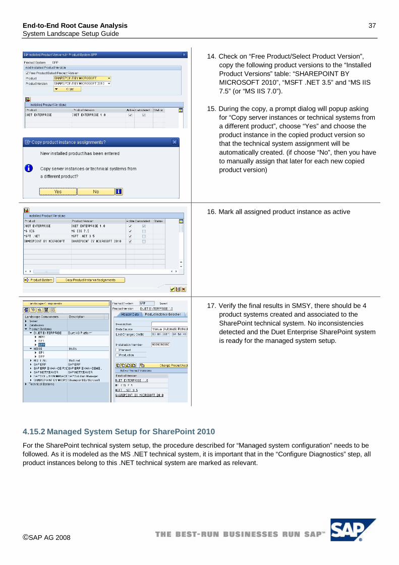
14. Check on “Free Product/Select Product Version”, copy the following product versions to the “Installed Product Versions” table: “SHAREPOINT BY MICROSOFT 2010”, “MSFT .NET 3.5” and “MS IIS 7.5” (or “MS IIS 7.0”).
15. During the copy, a prompt dialog will popup asking for “Copy server instances or technical systems from a different product”, choose “Yes” and choose the product instance in the copied product version so that the technical system assignment will be automatically created. (if choose “No”, then you have to manually assign that later for each new copied product version)
16. Mark all assigned product instance as active
17. Verify the final results in SMSY, there should be 4 product systems created and associated to the SharePoint technical system. No inconsistencies detected and the Duet Enterprise SharePoint system is ready for the managed system setup.
4.15.2 Managed System Setup for SharePoint 2010 For the SharePoint technical system setup, the procedure described for “Managed system configuration” needs to be followed. As it is modeled as the MS .NET technical system, it is important that in the “Configure Diagnostics” step, all product instances belong to this .NET technical system are marked as relevant.

End-to-End Root Cause Analysis 38 System Landscape Setup Guide
©SAP AG 2008
When you are asked for the system parameters of the MS .NET technical system, enter the Microsoft .NET framework root path (which is by default “C:\windows”) in the “System Installation Path” and mark the “Software Component Path” for the following product versions (please leave others empty): MS IIS 7.0 (or 7.5): C:\windows\system32\inetsrv\ MSFT .NET FRAMEWORK 3.5: C:\windows\ SHAREPOINT MOSS 2010: C:\Program Files\Common Files\Microsoft Shared\Web Server Extensions\14\
4.15.3 SMSY Adaption for SAP Gateway Server SAP Gateway Server (Service Consumption Layer) is based on SAP Netweaver 7.0 EHP2. After triggering the SLD data transfer in RZ70 of the managed system, in Solution Manager SMSY, an ABAP technical system will be created and SAP Netweaver 7.0 EHP2 product version is automatically assigned. We need to change it a little bit before the managed system setup.

End-to-End Root Cause Analysis 39 System Landscape Setup Guide
©SAP AG 2008
1. Start transaction SMSY. 2. Under Product System SAP Netweaver, locate
the SID for the Gateway Server. 3. Go to tab “Header Data”, click “Change Product
Assignmt” button.
4. In the free selection, add product instance DUET ENTERPRISE 1.0 to the assignment list.
5. Click “Save” button.
6. In the “Product Instance Selection” tab, mark “Service Adaption Layer” instance as relevant.
4.15.4 Managed System Setup for SAP Gateway Server In the “Managed system configuration” “Configure Diagnostics” step, please ONLY select the DUET ENTERPRISE 1.0 product, the Application Server ABAP and Service Adaption Layer instance will be automatically added.
The other setup steps are the same as the managed system setup for the normal SAP ABAP stack systems.

End-to-End Root Cause Analysis 40 System Landscape Setup Guide
©SAP AG 2008
4.16 Web Dispatcher 7.10 The automatic creation of the technical system for SAP Web Dispatcher 7.10 via SLD is currently not supported. As a consequence the technical system for SAP Web Dispatcher 7.10 has to be created manually before using the managed system wizard.
4.16.1 Manual creation of technical system for SAP Web Dispatcher 7.10
1. Open the System Maintenance application from the common tasks area of the Root Cause Analysis Workcenter (Transaction: SOLMAN_WORKCENTER).
2. Select “Create”.

End-to-End Root Cause Analysis 41 System Landscape Setup Guide
©SAP AG 2008
3. Enter the System ID of your SAP Web Dispatcher into field Technical System, select type “Web Dispatcher” and enter a description.
4. Select “Save”.
5. Select “Add Main Instance”. 6. Select the Product “SAP NETWEAVER AS ABAP”
Product Version “SAP NETWEAVER AS ABAP 7.1” Main Instance “SAP Web Dispatcher”.
7. Select “OK”. 8. Flag the System as “Production”. 9. Select “Save”.
10. Select Tab “Instances”. 11. Enter the SAP Web Dispatcher Instance in the following
format: <Server>_<SID>_<#>. 12. Enter the server name. 13. Choose server role “WEBDISPATCHER”. 14. Select Save.

End-to-End Root Cause Analysis 42 System Landscape Setup Guide
©SAP AG 2008
15. Go to transaction SMSY in Solution Manager system. 16. Go to Landscape Components System Components
Web Dispatcher. 17. Select the correct Web Dispatcher SID. 18. Click on the “Display/Change” button.
19. Go to the tab “Software Components”. 20. Change the release from 7.20 to 7.10. 21. Click on “Save”.
4.16.2 Diagnostics Configuration After setting up the technical system, the diagnostics configuration needs to be performed.
1. Open the configuration wizard for SAP Solution Manager (Transaction: SOLMAN_SETUP).
2. Select “Managed System Configuration”. 3. Select system type “WEBDISP”. 4. Select the previously created Web Dispatcher system. 5. Select “Configure System”.
6. Choose “Diagnostics Configuration”. 7. Start the diagnostics wizard using the link “Configure
Diagnostics”.

End-to-End Root Cause Analysis 43 System Landscape Setup Guide
©SAP AG 2008
8. Your system is pre-selected. 9. To mark the system as diagnostics relevant open the
tray.
10. Unselect the checkbox. 11. Select “Set”.
12. Select “Setup” to continue.

End-to-End Root Cause Analysis 44 System Landscape Setup Guide
©SAP AG 2008
13. Enter the file path where the SAP Web Dispatcher is installed (typically /usr/sap/<SID>).
14. Enter the instance number of the SAP Web Dispatcher instance.
15. Enter the http port of the Web Dispatcher Admin Page. 16. Enter the relative URL of the Web Dispatcher Admin
Page (typically /sap/admin). 17. Select “Set” to accept the parameters. 18. Select “Next” to continue the setup.
4.17 SAP MDM 5.5 SP06 and SAP Netweaver MDM 7.1 For SAP MDM an automated creation of the technical system via the SLD is currently not supported. Therefore you have to maintain the MDM system manually using the “Technical Systems” wizard. Afterwards perform the Diagnostics Configuration for the MDM system using the “Managed System Configuration” wizard.
4.17.1 Manual creation of technical system for MDM
1. Call transaction “SOLMAN_SETUP”. 2. Select “Managed System Configuration”. 3. Select “Maintain Technical Systems”.

End-to-End Root Cause Analysis 45 System Landscape Setup Guide
©SAP AG 2008
4. Select “Create”.
5. Enter the System ID of your MDM Server into field “Technical System”, select type “MDM Server” and enter a description.
6. Select “Save”.
Please note: SAP MDM 5.5 systems are not installed with a System ID, however, in order to identify the system uniquely in Diagnostics you need to make up and enter a unique system ID here.
7. Select “Add Main Instance”. 8. Depending on your MDM Product Version, select the
Product Version “SAP MDM 5.5” or the Product Version “SAP Netweaver MDM 7.1”. Select the Main Instance “Master Data Server”.
9. Select “Save”. 10. Flag the System as “Production”. 11. Select “Save”.
Please note: If you want to perform the Diagnostics setup for a SAP Netweaver MDM 7.1 system with SAP Solution Manager 7.0 < SP19, please refer to SAP Note 1268326.

End-to-End Root Cause Analysis 46 System Landscape Setup Guide
©SAP AG 2008
12. Select Tab “Instances”. 13. Enter the MDM System Instances, the Server and the
corresponding Server Roles. For the instance naming convention we recommend the following: <server>_<SID>_<instance number>.
14. If you cannot select the appropriate server from the value help, create a new server using the button “New Server”.
15. Select the Tab “Database”. 16. Enter the MDM Server Database via the value help or
create a new database and select “Save”.
17. Call transaction SMSY. 18. Select Landscape Components. 19. Select Product Systems -> SAP MDM -> <SID>. 20. Select tab “Product Instance Selection”. 21. Navigate to the table row with the Product Instance “Master
Data Server”. 22. Select flag “Relevant”. 23. Select flag “Technical System Assignment”. 24. Select the Technical System with the <SID> you just
created. 25. Select System “Type MDM Server”. 26. Save.
4.17.2 Diagnostics Configuration After setting up the technical system, the diagnostics configuration steps need to be performed.

End-to-End Root Cause Analysis 47 System Landscape Setup Guide
©SAP AG 2008
1. Open the configuration wizard for SAP Solution Manager (Transaction: SOLMAN_SETUP).
2. Select “Managed System Configuration”. 3. Select System Type “MDM”. 4. Select the previously created MDM system. 5. Select “Configure System”.
6. Perform the described activities for the managed system configuration. A description for each activity is available in the linked IMG documentation. For managed systems of type MDM only the following steps and activities are relevant: Step “Check Prerequisites”. Under step “Manual Configuration” the activities “Install
Diagnostics Agent” and “Configure DBA Cockpit”. Under step “Diagnostics Configuration” the activities
“SAP MDM-Specific Configuration” and “Configure Diagnostics”.
Step “Create logical Components”. 7. Set the execution status of each activity executed to
“Performed”.
8. The activity “Configure Diagnostics” starts the Setup Wizard.
9. If the system is marked as “Not Diagnostics Relevant”, proceed as follows:
a. Open the tray. b. Unselect the checkbox “Not Diagnostics Relevant”. c. Select “Set”.
10. Select “Setup” to continue the setup.
End-to-End Root Cause Analysis 48 System Landscape Setup Guide
©SAP AG 2008
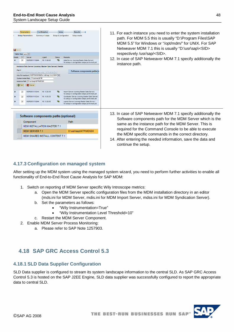
11. For each instance you need to enter the system installation path. For MDM 5.5 this is usually “D:\Program Files\SAP MDM 5.5” for Windows or “/opt/mdm/” for UNIX. For SAP Netweaver MDM 7.1 this is usually “D:\usr\sap\<SID> respectively /usr/sap/<SID>.
12. In case of SAP Netweaver MDM 7.1 specify additionally the instance path.
13. In case of SAP Netweaver MDM 7.1 specify additionally the Software components path for the MDM Server which is the same as the instance path for the MDM Server. This is required for the Command Console to be able to execute the MDM specific commands in the correct directory.
14. After entering the needed information, save the data and continue the setup.
4.17.3 Configuration on managed system After setting up the MDM system using the managed system wizard, you need to perform further activities to enable all functionality of End-to-End Root Cause Analysis for SAP MDM:
1. Switch on reporting of MDM Server specific Wily Introscope metrics: a. Open the MDM Server specific configuration files from the MDM installation directory in an editor
(mds.ini for MDM Server, mdis.ini for MDM Import Server, mdss.ini for MDM Syndication Server). b. Set the parameters as follows:
“Wily Instrumentation=True” “Wily Instrumentation Level Threshold=10”
c. Restart the MDM Server Component. 2. Enable MDM Server Process Monitoring:
a. Please refer to SAP Note 1257903.
4.18 SAP GRC Access Control 5.3
4.18.1 SLD Data Supplier Configuration SLD Data supplier is configured to stream its system landscape information to the central SLD. As SAP GRC Access Control 5.3 is hosted on the SAP J2EE Engine, SLD data supplier was successfully configured to report the appropriate data to central SLD.
End-to-End Root Cause Analysis 49 System Landscape Setup Guide
©SAP AG 2008
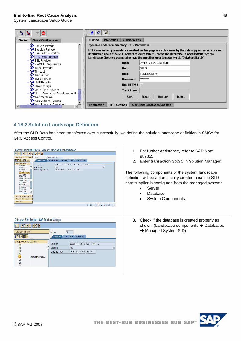
4.18.2 Solution Landscape Definition After the SLD Data has been transferred over successfully, we define the solution landscape definition in SMSY for GRC Access Control.
1. For further assistance, refer to SAP Note 987835.
2. Enter transaction SMSY in Solution Manager. The following components of the system landscape definition will be automatically created once the SLD data supplier is configured from the managed system:
Server Database System Components.
3. Check if the database is created properly as shown. (Landscape components Databases
Managed System SID).

End-to-End Root Cause Analysis 50 System Landscape Setup Guide
©SAP AG 2008
4. Check if the system component is created properly as shown. (Landscape components Java Managed System SID).
Creation of systems: Systems have to be manually created. The end result of creating a system in SMSY for SAP GRC Access Control 5.3 should look like as follows (NOTE: A SAP Netweaver product version was added manually to complete the creation of a system for SAP GRC Access Control 5.3). Please follow the steps below to complete the creation of a system.
1. Create a system with the following information; use “Managed System SID” for the System.
End-to-End Root Cause Analysis 51 System Landscape Setup Guide
©SAP AG 2008
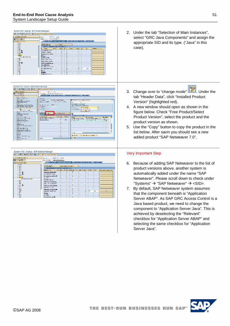
2. Under the tab “Selection of Main Instances”, select “GRC Java Components” and assign the appropriate SID and its type. (“Java” in this case).
3. Change over to “change mode” . Under the tab “Header Data”, click “Installed Product Version” (highlighted red).
4. A new window should open as shown in the figure below. Check “Free Product/Select Product Version”, select the product and the product version as shown.
5. Use the “Copy” button to copy the product in the list below. After savin you should see a new added product “SAP Netweaver 7.0”.
Very Important Step 6. Because of adding SAP Netweaver to the list of
product versions above, another system is automatically added under the name “SAP Netweaver”. Please scroll down to check under “Systems” “SAP Netweaver” <SID>.
7. By default, SAP Netweaver system assumes that the component beneath is “Application Server ABAP”. As SAP GRC Access Control is a Java based product, we need to change the component to “Application Server Java”. This is achieved by deselecting the “Relevant” checkbox for “Application Server ABAP” and selecting the same checkbox for “Application Server Java”.

End-to-End Root Cause Analysis 52 System Landscape Setup Guide
©SAP AG 2008
4.18.3 Managed System Setup Wizard The managed system setup wizard is used after the GRC Access Control 5.3 solution landscape has been designed in SMSY. This is the final step towards completing the Solution Manager Diagnostics setup for GRC Access Control 5.3.
1. In the Managed System Setup Wizard, select the appropriate SID of the managed system.
2. As the product versions “SAP GRC Access Control 5.3” and “SAP Netweaver 7.0” both were added during the SMSY setup, we should be able to see the same in the wizard. Use the CTRL key to select both product versions and click on “Set”. The result should like as shown in the figure. Click next to add the System installation path and Instance path of the GRC Access Control 5.3 application.
3. In the figure shown: System Install Path : C:\usr\sap\<SID>. Instance Path: C:\usr\sap\<SID>\JCxx. Click on “Set” and “Next” to finish this step.

End-to-End Root Cause Analysis 53 System Landscape Setup Guide
©SAP AG 2008
4. Before the setup of managed system setup wizard we should see the following screen.
5. After the setup is finished the screen should look like as shown.
4.19 SAP PPM by IDS Scheer 4.1 For SAP PPM by IDS Scheer 4.1, an automated creation of the technical system via the SLD is currently not supported. Therefore you have to create the technical system manually and then connect the managed system using the managed system wizard.

End-to-End Root Cause Analysis 54 System Landscape Setup Guide
©SAP AG 2008
4.19.1 Manual Creation of Technical System for SAP PPM by IDS Scheer 4.1
1. Log on to the Solution Manager system. 2. Open the system maintenance application from Common
Tasks area of the Root Cause Analysis Workcenter (Transaction SOLMAN_WORKCENTER).
3. Select “Create”.

End-to-End Root Cause Analysis 55 System Landscape Setup Guide
©SAP AG 2008
4. Enter a System ID for your SAP PPM by IDS Scheer 4.1 (LBP) into the field “Technical System”, select type “Unspecified” and enter a description, i.e. “Technical System for SAP PPM by IDS Scheer 4.1 for SP18”.
5. Select “Save”.
6. Select “Add Main Instance”. 7. Select the Product Version “SAP PPM by IDS 4.1” Main
Instance “Process Extractor SAP-2-PPM”. 8. Repeat the above step to add “Process Performance
Manager” for the above Product Version. 9. Flag the System as “Production”. 10. Select “Save”.
11. Select Tab “Instances”. 12. Enter the LBP System Instance, the Server and the
corresponding Operating System and its version. i.e. “PPM41_vmw2464”.
13. If you cannot select the appropriate server from the value help, create a new server using the button “New Server”.

End-to-End Root Cause Analysis 56 System Landscape Setup Guide
©SAP AG 2008
14. Select Tab “Database”. 15. Check “Maintain Database Use” checkbox. 16. Enter the LBP Server Database via the value help or create
a new database and select “Save”.
4.19.2 Managed System Setup Wizard After setting up the technical system with SMSY Wizard, the managed system setup wizard is used for the SAP PPM by IDS Scheer 4.1 solution manager diagnostics setup.
1. In Solution Manager Diagnostics, go to Diagnostics Setup Managed Systems Setup Wizard and enter the SID
in the “Jump to SID” field.

End-to-End Root Cause Analysis 57 System Landscape Setup Guide
©SAP AG 2008
1. Expand the breadcrumb in the “detail” and un-check “Not Diagnostics Relevant”.
2. Select product version and click on “Set”.
3. Set the installation path to “D:/ppm4/” and Component Paths as specified Click on “Set” and “Next” to finish this step.
4. Before setup, we should see the screen similar to the one shown on the left.
5. After setup, we should see the screen similar to the one shown on the left.

End-to-End Root Cause Analysis 58 System Landscape Setup Guide
©SAP AG 2008
4.20 SAP PMM by Vendavo 6.7, 7.0, 7.1, 7.5
4.20.1 SLD Data Supplier Configuration SLD Data supplier is configured to stream its system landscape information to the central SLD. As SAP PMM by Vendavo 6.7, 7.0, 7.1, 7.5 is hosted on the SAP J2EE Engine, SLD data supplier was successfully configure to report the appropriate data to central SLD.
4.20.2 Solution Landscape Definition After the SLD Data has been transferred over successfully, we define the solution landscape definition in SMSY for SAP PMM by Vendavo 6.7, 7.0, 7.1, 7.5
1. Log on to the Solution Manager system. 2. For further assistance, refer to SAP Note 987835. 3. Enter transaction SMSY in Solution Manager. The following components of the system landscape definition will be automatically created because of the SLD data supplier from the managed system:
Server Database System Components
Check if the server is created properly as shown below (i.e. Landscape components Server vmw2464).

End-to-End Root Cause Analysis 59 System Landscape Setup Guide
©SAP AG 2008
4. Check if the database is created properly as shown to the left (i.e. Landscape components Databases LB2).
5. Check if the system component is created properly as shown to the left (i.e. Landscape components Java
LB2). 6. The PMM components for 6.7, 7.0 and 7.1 should
show following PRICE_MANAGER 6.7/7.0/7.1 PRICE_OPTMZER 6.7/7.0/7.1 PROFIT_ANALYZER 6.7/7.0/7.1 DEAL_MANAGER 6.7/7.0/7.1
The PMM component for 7.5 should show
PMM_VENDAVO 7.5 Note: If it is not the case as specified in step 6, you can choose the software components specific to your installed product release manually by selecting the From Main Instance command button in change mode.
7. Check the instances are selected.
Fig.1
8. Creation of systems: Systems are created /refreshed via SLD data. The end result of creating a system in SMSY for SAP PMM by Vendavo 6.7 should look like to the left,(NOTE: A SAP Netweaver product version was added manually to complete the creation of a

End-to-End Root Cause Analysis 60 System Landscape Setup Guide
©SAP AG 2008
Fig 2
Fig 3
Fig.4
Fig 5
Fig 6.
system for “SAP PMM by Vendavo 6.7”).\ In Case of PMM 7.0 the system should have following products assigned ( Fig 1)
SAP NETWEAVER 7.0 SAP PRICE & MARGIN MGT 7.0
In Case of PMM 7.1 the system should have following products assigned ( Fig 2)
SAP NETWEAVER 7.1 SAP PRICE & MARGIN MGT 7.1
In Case of PMM 7.5 the system should have following products assigned (Fig 3)
SAP NETWEAVER CE 7.1 SAP PRICE & MARGIN MGT 7.5
If the Product versions are not assigned as mentioned in step 7 then proceed as follows:-
Switch to “change mode” .
Click on “ Select the Product and Product Versions as
mentioned in Fig 6 & 7.

End-to-End Root Cause Analysis 61 System Landscape Setup Guide
©SAP AG 2008
Please use the following instructions to complete the step:
9. Under the tab “Selection of Main Instances”, select “Application Server” and assign the appropriate SID (example: LB200001).
10. Change over to “change mode” . Under the tab “Header Data”, click “Installed Product Version”. A new window should open as shown in the figure below. Check “Free Product/Select Product Version”, select the product and the product version as shown to the left.
11. Use the “Copy” button to copy the product in the list below. Save the selection and one should see a new product “SAP Netweaver 7.0” added.
12. Very Important Step Because of adding SAP Netweaver to the list of product versions above, another system is automatically added under the name “SAP Netweaver”. Please scroll down to check under “Systems” “SAP Netweaver” LBH. By default, SAP Netweaver system assumes that the component beneath is “Application Server ABAP”. As SAP PMM is a Java based product, we need to change the component to “Application Server Java”. This is achieved by de-selecting the “Relevant” checkbox for “Application Server ABAP” and selecting the same checkbox for “Application Server Java”. See the figure to the left.

End-to-End Root Cause Analysis 62 System Landscape Setup Guide
©SAP AG 2008
4.20.3 Managed System Setup Wizard The managed system setup wizard is used after the SAP PMM by Vendavo 6.7, 7.0, 7.1, 7.5 solution landscape has been designed in SMSY. This is the final step towards completing the Solution Manager Diagnostics setup for SAP PMM by Vendavo 6.7, 7.0, 7.1, 7.5
1. Using Solution Manager Diagnostics go to Diagnostics Setup Managed Systems Setup Wizard, enter the SID in the “Jump to SID” field and hit “Enter”.

End-to-End Root Cause Analysis 63 System Landscape Setup Guide
©SAP AG 2008
2. As the product versions SAP PMM by Vendavo 6.7, and SAP Netweaver 7.0 both were added in the previous step, we should be able to see the same in the wizard. Use the CTRL key to select both product versions and click on “Set”. Note: Based on your installation you have to choose your product version: SAP PMM by Vendavo 6.7, 7.0, 7.1, 7.5
3. The result should like as shown to the left.
4. Click next to add the details in the next screen as shown to the left.
Set the install path for PMM 6.7 as follows. Example: D:/Vendavo/ and expand and enter correct optional component path for all the components, i.e. DEAL_MANAGER, PRICE_MANAGER, PRICE_OPTMZER, and PROFIT_ANALYZER to d:/Vendavo/. Set the install path for PMM 7.0,7.1 as follows. Example D:\Vendavo-NetWeaver\7.1\ for the PMM components, i.e. PRICE MANAGER 7.0,7.1, PRICE OPTIMIZER, 7.0,7.1 PROFIT_ANALYZER 7.0,7.1, DEAL MANAGER 7.0,7.1 Set the install path for PMM 7.5 Software component will be

End-to-End Root Cause Analysis 64 System Landscape Setup Guide
©SAP AG 2008
D:/PMM_VENDAVO 7.5/
5. Before setup, we should see similar screen as shown to the left.
6. After setup, the results are as shown to the left.
4.21 SAP Strategy Management 7.0/7.5
4.21.1 SLD Data Supplier Configuration SLD Data supplier is configured to stream its system landscape information to the central SLD. SAP Strategy

End-to-End Root Cause Analysis 65 System Landscape Setup Guide
©SAP AG 2008
Management 7.0 or 7.5 is hosted on the SAP J2EE Engine, SLD data supplier can be configured to report the appropriate data to central SLD.
4.21.2 Solution Landscape Definition After the SLD Data has been transferred over successfully, we define the solution landscape definition in SMSY for SAP Strategy Management 7.0 or 7.5.
1. Log on to the Solution Manager system. 2. For further assistance, refer to SAP Note 987835. 3. Enter transaction SMSY in Solution Manager. The following components of the system landscape definition will be created automatically once the SLD data supplier is defined from the Managed system.
Server Database System Components
Check if the server is created properly as shown below (i.e. Landscape components Server jhyv00459520b).
Check if the system component is created properly as shown to the left (i.e. Landscape components Java LB2).

End-to-End Root Cause Analysis 66 System Landscape Setup Guide
©SAP AG 2008
4. Creation of Systems: Systems have to be manually created. The end result of creating a system in SMSY for SAP Strategy Management 7.5 should look like as follows (NOTE: A SAP Netweaver product version was added manually to complete the creation of a “System” for “SAP Strategy Management 7.5).
Please use the following instructions to complete the Step: 5. Create a system (i.e. “CEY”).
6. Under the tab “Selection of Main Instances”, select Application Component on NW CE, Application Server, Frontend Diagram Manager, Frontend Excel Addin, Interactive Publisher and assign the appropriate SID (i.e. CE100002).

End-to-End Root Cause Analysis 67 System Landscape Setup Guide
©SAP AG 2008
7. Change over to “change mode”. Under the tab “Header Data”, click “Installed Product Version”. A new window should open as shown in the figure below. Check “Free Product/Select Product Version”, select the product and the product version as shown to the left.
8. Use the “Copy” button to copy the product in the list below. Save the selection and one should see a new product “SAP Netweaver 7.1” added.
9. Very Important Step Because of adding SAP Netweaver to the list of product versions above, another system is automatically added under the name “SAP Netweaver”. Please scroll down to check under “Systems” “SAP Netweaver” CEA. By default, SAP Netweaver system assumes that the component beneath is “Application Server ABAP”. As SAP Strategy Management is a Java based product, we need to change the component to “Application Server Java”. This is achieved by deselecting the “Relevant” checkbox for “Application Server ABAP” and selecting the same checkbox for “Application Server Java”. See the figure to the left.

End-to-End Root Cause Analysis 68 System Landscape Setup Guide
©SAP AG 2008
4.21.3 Managed System Setup Wizard The managed system setup wizard is used after the SAP Strategy Management 7.0 or 7.5 Solution Landscape has been defined in SMSY. This is the final step towards completing the Solution Manager Diagnostics setup for SAP Strategy Management 7.0 or 7.5.
1. Using Solution Manager Diagnostics go to Diagnostics Setup Managed Systems Setup Wizard, enter the SID in the “Jump to SID” field and hit “enter”.
2. As the product versions SAP Strategy Management 7.0/7.5 and SAP Netweaver 7.1 both were added in Step 14, we should be able to see the same in the wizard. Use the CTRL key to select both product versions and click on “Set”.
3. The result should look like as shown in the screen on the left.

End-to-End Root Cause Analysis 69 System Landscape Setup Guide
©SAP AG 2008
4. Click next to add the details in the next screen as shown to the left. Remember to expand and enter correct optional component path for all the components, i.e. SAP STR. MGM. INT. PUB. 7.5:
C:/Program Files/SAP/SSM/InternetPub/ SAP STR. MGM. AP. COMP. 7.5: C:/
And for Install path, use i.e. C:/Program Files/SAP/SSM/.
5. Before setup, we should see the screen similar to the one shown on the left.
6. After setup, we should see the screen similar to the one shown on the left.
4.22 SAP BusinessObjects PCM 11.3
4.22.1 Manual Creation of Technical System for SAP BusinessObjects PCM 11.3 For SAP BusinessObjects PCM 11.3, an automated creation of the technical system via the SLD is currently not supported. Therefore, you have to create the technical system manually and then run managed system setup wizard.

End-to-End Root Cause Analysis 70 System Landscape Setup Guide
©SAP AG 2008
1. Log on to the Solution Manager system. Open the system maintenance application from Common Tasks area of the Root Cause Analysis Workcenter (Transaction SOLMAN_WORKCENTER).
2. Select “Create”.

End-to-End Root Cause Analysis 71 System Landscape Setup Guide
©SAP AG 2008
3. Enter a System ID for your SAP BusinessObjects PCM 11.3 (PCM) into the field “Technical System”, select type “Unspecified” and enter a description, i.e. “Technical System for SAP BusinessObjects PCM 11.3”.
4. Select “Save”.
5. Select “Add Main Instance”. 6. Select the Product Version “BOBJ PCM 11.3
SP1” Main Instance “BOBJ ACTIVITY ANALYSIS”.
7. Flag the System as “Production”. 8. Select “Save”.
9. Select Tab “Instances”. 10. Enter the PCM System Instance, the Server and
the corresponding Operating System and its version. i.e. PCM113_VMW2586.
11. If you cannot select the appropriate server from the value help, create a new server using the button “New Server”.

End-to-End Root Cause Analysis 72 System Landscape Setup Guide
©SAP AG 2008
12. Select the Tab “Database”. 13. Check “Maintain Database Use” checkbox. 14. Enter the PCM Server Database via the value
help or create a new database. 15. Select “Save”.
4.22.2 Managed System Setup Wizard After setting up the technical system with SMSY Wizard, the managed system setup wizard is used for the SAP BusinessObjects PCM 11.3 solution manager diagnostics setup.
1. In Solution Manager Diagnostics go to Diagnostics Setup Managed Systems Setup Wizard, enter the SID in the “Jump to SID” field and hit “enter”.

End-to-End Root Cause Analysis 73 System Landscape Setup Guide
©SAP AG 2008
2. Expand the breadcrumb in the “detail” and Uncheck “Not Diagnostics Relevant”.
3. Select product version and click on “Set”.
4. Set the installation path (i.e. “D:/Program Files/Business Objects/Profitability/”) and click “Next” to finish this step.
5. Before setup, we should see the screen similar to the one shown on the left.

End-to-End Root Cause Analysis 74 System Landscape Setup Guide
©SAP AG 2008
6. After setup, we should see the screen similar to the one shown on the left.
4.23 SAP BOBJ Extended Analytics 7.0 For SAP BOBJ Extended Analytics an automated creation of the technical system via the SLD is currently not supported. Therefore you have to create the technical system manually and afterwards perform the managed system configuration using the Diagnostics setup wizard.
4.23.1 Manual creation of technical system for SAP BOBJ Extended Analytics
1. Go to the transaction /nSOLMAN_WORKCENTER and choose Root Cause Analysis tab. Open the System Maintenance Application from the Common Tasks area
2. Select Create

End-to-End Root Cause Analysis 75 System Landscape Setup Guide
©SAP AG 2008
3. Enter a System ID for SAP BOBJ Extended Analytics into the field “Technical System”, select type “MS. Net” and enter a description
4. Select Save
5. Select “Add Main Instance” 6. Select the Product Version “BOBJ Extended Analytics
7.0” Main Instance 7. Repeat the above step to add Product Version “MS IIS
6.0” Main Instance “MS IIS” 8. Select the Product Version “MSFT .NET 2.0” Main
Instance “MSFT .Net Framework” 9. Flag the System as “Production” 10. Select Save
11. Select Tab “Instances”. 12. Enter the BOBJ Extended Analytics 7.0 Instance, the
Server and the corresponding Operating System and its version. For the instance naming convention we recommend the following: <server>_<SID>_<Instance#>
13. If you cannot select the appropriate server from the value help, create a new server using the button

End-to-End Root Cause Analysis 76 System Landscape Setup Guide
©SAP AG 2008
14. Select Tab “Database”. 15. Enter the BOBJ Extended Analytics Database via the
value help or create a new database and select “Save”
4.23.2 Diagnostics Configuration After setting up the technical system, the diagnostics configuration needs to be performed.
1. Open the Managed System Configuration wizard for SAP Solution Manager (Transaction: SOLMAN_SETUP)
2. Select Managed System Configuration 3. Select system type MS_.NET 4. Select the BOBJ Extended Analytics System 5. Select Configure System

End-to-End Root Cause Analysis 77 System Landscape Setup Guide
©SAP AG 2008
6. Perform the described steps for the managed system of BOBJ Extended Analytics
7. Set the status of the activity to performed 8. Start the diagnostics wizard using the link Configure
Diagnostics
9. Your system is pre-selected 10. To mark the system as diagnostics relevant open the tray
11. If it is set to Not Diagnostic Relevant then Unselect the checkbox
12. Select BOBJ Extended Analytics Product Version 13. Select Set 14. Select Setup to continue the setup

End-to-End Root Cause Analysis 78 System Landscape Setup Guide
©SAP AG 2008
15. For each instance you need to enter the system installation path (e.g. D\Program Files\Business Objects\) and select set.
16. After entering the needed information, save the data and continue the setup.
17. In the last step, status of green indicates as successful completion. Yellow indicator may signal some warnings exist.
4.24 SAP BusinessObjects InterCompany 5.1 For SAP BusinessObjects InterCompany 5.1 an automated creation of the technical system via the SLD is currently not supported. Therefore you have to create the technical system manually and afterwards perform the managed system configuration using the Diagnostics Setup Wizard.
4.24.1 Manual creation of technical system for SAP BusinessObjects InterCompany 5.1
1. Go to the transaction SOLMAN_WORKCENTER and choose “Root Cause Analysis” tab. Open the “System Maintenance Application” from the Common Tasks area.
2. Select “Create”.

End-to-End Root Cause Analysis 79 System Landscape Setup Guide
©SAP AG 2008
3. Enter a System ID for SAP InterCompany into the field “Technical System”, select type “MS .Net” and enter a description.
4. Select “Save”.
5. Select “Add Main Instance”. 6. Select the Product Version “BOBJ Inter Company 5.1”
Main Instance. 7. Repeat the above step to add Product Version “MS IIS
5.0” Main Instance “MS IIS”. 8. Select the Product Version “MSFT .NET 2.0” Main
Instance “MSFT .Net Framework”. 9. Flag the System as “Production”. 10. Select “Save”.
11. Select Tab “Instances”. 12. Enter the Inter Company System Instance, the Server and
the corresponding Operating System and its version. For the instance naming convention we recommend the following: <server>_<SID>_<#>.
13. If you cannot select the appropriate server from the value help, create a new server using the button “New Server”.
14. Select tab “Database”. 15. Enter the BOBJ InterCompany Server Database via the
value help or create a new database and select “Save”.
4.24.2 Diagnostics Configuration After setting up the technical system, the diagnostics configuration needs to be performed.

End-to-End Root Cause Analysis 80 System Landscape Setup Guide
©SAP AG 2008
1. Open the Managed System Configuration wizard for SAP Solution Manager (Transaction: SOLMAN_SETUP).
2. Select “Managed System Configuration”. 3. Select system type “MS .NET”. 4. Select the “BOBJ InterCompany 5.1” System. 5. Select “Configure System”.
6. Perform the described steps for the managed system of BOBJ InterCompany 5.1.
7. Set the status of the activity to “performed”. 8. Start the diagnostics wizard using the link “Configure
Diagnostics”.
9. Your system is pre-selected. 10. To mark the system as diagnostics relevant open the tray.
11. Un-select the checkbox. 12. Select MS IIS 5.0, MSFT .NET 2.0 and BOBJ Inter
Company 5.1 Product Versions. 13. Select “Set”. 14. Select “Setup” to continue the setup.

End-to-End Root Cause Analysis 81 System Landscape Setup Guide
©SAP AG 2008
15. For each instance you need to enter the system installation path (e.g. D:\Program Files\Business Objects\) and select “Set”.
16. After entering the needed information, save the data and continue the setup.
4.25 SAP BusinessObjects Planning Extended 5.3 For SAP BusinessObjects Planning Extended 5.3 an automated creation of the technical system via the SLD is currently not supported. Therefore you have to create the technical system manually and afterwards perform the managed system configuration using the Diagnostics Setup Wizard.

End-to-End Root Cause Analysis 82 System Landscape Setup Guide
©SAP AG 2008
4.25.1 Manual creation of technical system for SAP BusinessObjects Planning Extended 5.3
1. Go to the transaction SOLMAN_WORKCENTER and choose ”Root Cause Analysis” tab. Open the “System Maintenance Applicatio”n from the Common Tasks area.
2. Select “Create”.
3. Enter a System ID for your SAP Planning Extended into the field “Technical System”, select type “MS .Net” and enter a description.
4. Select “Save”.

End-to-End Root Cause Analysis 83 System Landscape Setup Guide
©SAP AG 2008
5. Select “Add Main Instance”. 6. Select the Product Version “BOBJ Planning Extended 5.3”
Main Instance. 7. Repeat the above step to add Product Version “MS IIS
5.0” Main Instance “MS IIS”. 8. Select the Product Version “MSFT .NET 2.0” Main
Instance “MSFT .Net Framework”. 9. Flag the System as “Production”. 10. Select “Save”.
11. Select Tab “Instances”. 12. Enter the Planning Extended System Instance, the Server
and the corresponding Operating System and its version. For the instance naming convention we recommend the following: <server>_<SID>_<#>.
13. If you cannot select the appropriate server from the value help, create a new server using the button “New Server”.
14. Select tab “Database”. 15. Enter the Server Database via the value help or create a
new database and select “Save”.

End-to-End Root Cause Analysis 84 System Landscape Setup Guide
©SAP AG 2008
4.25.2 Diagnostics Configuration After setting up the technical system, the diagnostics configuration needs to be performed.
1. Open the “Managed System Configuration Wizard” for SAP Solution Manager (Transaction SOLMAN_SETUP).
2. Select “Managed System Configuration”. 3. Select system type “MS .NET”. 4. Select the “BOBJ Planning Extended 5.3” System. 5. Select “Configure System”.
6. Perform the described steps for the managed system of type BOBJ Planning Extended.
7. Set the status of the activity to “performed”. 8. Start the diagnostics wizard using the link “Configure
Diagnostics”.
9. Your system is pre-selected. 10. To mark the system as diagnostics relevant open the tray.
Un-select the checkbox. 11. Select MS IIS 5.0, MSFT .NET 2.0 and BOBJ Planning
Extended 5.3 Product Versions. 12. Select “Set”. 13. Select “Setup” to continue the setup.

End-to-End Root Cause Analysis 85 System Landscape Setup Guide
©SAP AG 2008
14. For each instance you need to enter the system installation path (e.g. D:\Program Files\Business Objects\) and select “Set”.
15. After entering the needed information, save the data and continue the setup.
4.26 SAP BOBJ Financial Consolidation (BOFC) 7.0/7.5 or Finance 10.5 (XiR2)
For SAP BOFC an automated creation of the technical system via the SLD is currently not supported. Therefore you have to create the technical system manually and afterwards perform the managed system configuration using the Diagnostics setup wizard.
4.26.1 Configuration on managed system Managed system needs to be configured with Wily Introscope .NET Agent as well as the Diagnostics Agent.
To switch on reporting of SAP specific Wily Introscope metrics: o Install Wily Introscope .NET Agent as per the SAP Note 1126554 o Restart the IIS Server.
Download and Install the Diagnostics Agent from Service Marketplace
4.26.2 Manual creation of technical system for SAP BOFC
1. Go to the system landscape transaction (/nSMSY) in Solution Manager. Create a new system component by right click on “System Components” in the landscape components section. Select a unique system ID and type “MS .Net”. In case the system ID has more than three characters the entry need to be confirmed by return key before it can be saved.

End-to-End Root Cause Analysis 86 System Landscape Setup Guide
©SAP AG 2008
2. Navigate in the system component tree to the created system component of type “Unspecified” and fill in free instance names and assign appropriate servers from the drop down list. For the instance naming convention we recommend the following: <Server>_<SID>_<Instance#> If you have not created the server previously you may have to create a new server by right click on “Server” from the landscape components selection. Fill in the host name and add after saving the fully qualified hostname, IP address and OS version in the “Technical Data” tab.
3. Confirm a second time by return key when saving.
4. Navigate to the “Software Components” tab of the newly created system component and add the installed software components using the “from Main Instance” button. BOBJ FINANCIAL CONSOLIDATION BOBJ FINANCIAL CONS. 10.5/7.0/7.5 Fin.Cons. Appl. Serv. If the web client scenario is used in the BOFC installation also add: BOBJ FINANCIAL CONSOLIDATION BOBJ FINANCIAL CONS. 10.5/7.0/7.5 Fin.Cons. Web Server Specific to BOFC 7.5 choose additionaly. MSFT .NET MSFT .NET 2.0 MSFT .NET FRAMEWORK MS IIS MS IIS 6.0/MS IIS 7.0 MS IIS (in case of the web scenario) For BOFC 10.5/7.0 please choose the Main Instance:

End-to-End Root Cause Analysis 87 System Landscape Setup Guide
©SAP AG 2008
MSFT .NET MSFT .NET 1.1 MSFT .NET FRAMEWORK MS IIS MS IIS 5.0/MS IIS 6.0 MS IIS (in case of the web scenario)
5. Save the selection.
6. Create a new database by right click on landscape component “Databases” and maintain the “Technical Data” tab.
7. Create a new system by right click on the “Systems” node of the landscape components section. Select the same system ID as for the system components. Then select the product “BOBJ FINANCIAL CONSOLIDATION” and your product version. In case you create a SID with more than three characters you need to confirm by return key before the data can be saved.

End-to-End Root Cause Analysis 88 System Landscape Setup Guide
©SAP AG 2008
8. Find the system in the “System” navigation tree under product “BOBJ FINANCIAL CONSOLIDATION”. Go to the “Header Data” tab and choose the “Installed Product Versions” button. Then hook the “Free Product” checkbox and select depending on the BOFC product version the following additional product versions and copy them to the list. In case of BOBJ FINANCIAL CONSOLIDATION 7.5: MS IIS MS IIS 6.0/MS IIS 7.0 (only for the web scenario) MSFT .NET MSFT .NET 2.0 In case of BOBJ FINANCIAL CONSOLIDATION 10.5/7.0: MS IIS MS IIS 5.0/MS IIS 6.0 (only for the web scenario) MSFT .NET MSFT .NET 1.1
9. Navigate to tab “Selection of Main Instances” and mark the main instances “Fin.Cons Appl. Serv.” and “Fin.Cons Web Server” (only for the web scenario) as relevant. Furthermore hook the system component assignment checkboxes for these two main instances and assign the previously created system component of type MS .Net to both relevant main instances by drop down lists. Save the system.
10. Choose the system ID in the navigation tree for product “MS IIS” (in case of the web scenario) of the system landscape components and assign for main instance MS IIS the same system component relevant as previously done for main instances of product ”BOBJ FINANCIAL CONSOLIDATION”. Save the system.
11. Repeat this step for product “MSFT .NET” of the system landscape components and assign the system component to main instance “MSFT .Net Framework”. Save the system.
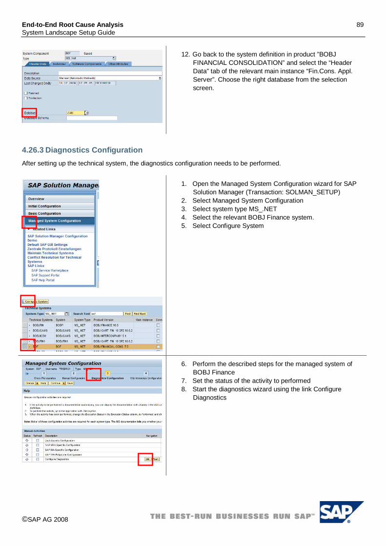
End-to-End Root Cause Analysis 89 System Landscape Setup Guide
©SAP AG 2008
12. Go back to the system definition in product ”BOBJ FINANCIAL CONSOLIDATION” and select the “Header Data” tab of the relevant main instance “Fin.Cons. Appl. Server”. Choose the right database from the selection screen.
4.26.3 Diagnostics Configuration After setting up the technical system, the diagnostics configuration needs to be performed.
1. Open the Managed System Configuration wizard for SAP Solution Manager (Transaction: SOLMAN_SETUP)
2. Select Managed System Configuration 3. Select system type MS_.NET 4. Select the relevant BOBJ Finance system. 5. Select Configure System
6. Perform the described steps for the managed system of BOBJ Finance
7. Set the status of the activity to performed 8. Start the diagnostics wizard using the link Configure
Diagnostics

End-to-End Root Cause Analysis 90 System Landscape Setup Guide
©SAP AG 2008
9. Your system is pre-selected 10. To mark the system as diagnostics relevant open the tray. 11. Select specific to your requirements (version BOBJ
FINANCIAL CONS 10.5, 7.0 or 7.5, MS IIS 5.0/6.0/7.0 [depending on the BOFC version and only when web client scenario is used] and depending on the BOFC version MSFT .Net 1.1/2.0)
12. Select Set 13. Check in the main instances tray whether there are
Fin.Cons Appl. Serv, Fin.Cons Web Server (in case of the web scenario), MS IIS (in case of the web scenario) and MSFT .Net Framework selected.
14. Select Set 15. Select Setup to continue the “Setup <SID>(system type)”.
16. For each instance you need to enter the BOFC system installation path: Ensure to enter the BOFC system installation path relevant to your installation.
Example: BOFC 10.5 - C:\Program Files\Business Objects\ BOFC 7.0 - C:\Program Files\Business Objects\ BOFC 7.5 - C:\Program Files\SAP BusinessObjects\ Furthermore insert the component install path after expanding the Software components paths tray. Make sure that there are paths included for: BOBJ. FINANCIAL CONS 10.5/7.0/7.5 (Default: C:\Program Files\Business Objects\), MSFT .Net 1.1/2.0 (Default:C:\Windows) and in case of a web client installation MS IIS 5.0/6.0/7.0 (Default: C:\Windows) and BOBJ FIN.CONS. WEB SITE 10.5/7.0/7.5 (Default:C:\Windows)

End-to-End Root Cause Analysis 91 System Landscape Setup Guide
©SAP AG 2008
17. Select “Set” after the right Wily EM has been chosen. 18. After entering the needed information, save the data and
continue the setup 19. In the last step, status of green indicates as successful
setup completion.
20. Please refer to SAP Note 1365266 to perform the configuration of Wily Introscope Agent and to setup Database Monitoring.
4.27 SAP ePOS 3.1 For SAP ePOS an automated creation of the technical system via the SLD is currently not supported. Therefore you have to create the technical system manually and afterwards run connect the managed system using the managed system wizard.
4.27.1 Manual creation of technical system for ePOS
1. Open the system maintenance application from the common tasks area of the “Root Cause Analysis” work center (Transaction SOLMAN_WORKCENTER).
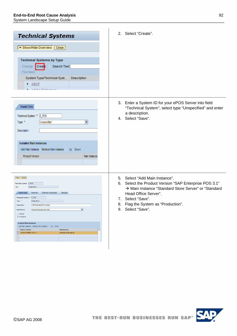
End-to-End Root Cause Analysis 92 System Landscape Setup Guide
©SAP AG 2008
2. Select “Create”.
3. Enter a System ID for your ePOS Server into field “Technical System”, select type “Unspecified” and enter a description.
4. Select “Save”.
5. Select “Add Main Instance”. 6. Select the Product Version “SAP Enterprise POS 3.1”
Main Instance “Standard Store Server” or “Standard Head Office Server”.
7. Select “Save”. 8. Flag the System as “Production”. 9. Select “Save”.

End-to-End Root Cause Analysis 93 System Landscape Setup Guide
©SAP AG 2008
10. Select Tab “Instances”. 11. Enter the ePOS Store System Instances, the Server
and the corresponding Server Roles. For the instance naming convention we recommend the following: <server>_<SID>_<#>.
12. If you cannot select the appropriate server from the value help, create a new server using the button “New Server”.
13. Select Tab “Database”. 14. You can’t create a Database server here. You have to
use transaction code “SMSY” in ABAP stack to create Database and select ePOS server. After Database is created, you should be able to see Database information after you select “Database”.

End-to-End Root Cause Analysis 94 System Landscape Setup Guide
©SAP AG 2008
4.27.2 Diagnostics Configuration After making sure that your SAP ePOS system is set up correctly, you can proceed with the diagnostics configuration for you SAP ePOS system.
1. Open the diagnostics setup application from the common tasks area of the “Root Cause Analysis” work center (Transaction SOLMAN_WORKCENTER).
2. Choose “Managed Systems”. 3. Choose “Setup Wizard”.
4. Jump to the SID of your ePOS.
5. Set the ePOS as “Diagnostics Relevant”. 6. Start the Setup using the “Setup SID
(PRODUCT)” button.

End-to-End Root Cause Analysis 95 System Landscape Setup Guide
©SAP AG 2008
7. In the Setup Parameters step, ensure the following settings:
a. Select your Wily Server. b. Please fill in n the System Install Path:
/opt/ if your installation path is selected as this; otherwise enter your system installation path.
8. After this is done, continue with the setup.
9. Select the Wily Server. 10. After a successful setup you should see a green
traffic light. If there is some warning then the traffic light is yellow.
11. Ensure wily host agent is reporting to Enterprise Manager
12. For Wily Agent Installation and Setup refer to ePOS Operational Guide document
4.28 SAP Manufacturing Execution (ME) 5.1
4.28.1 Sending Data to System Landscape Directory

End-to-End Root Cause Analysis 96 System Landscape Setup Guide
©SAP AG 2008
SLD Data Supplier is configured to stream its system landscape information to the central SLD. As SAP ME 5.1 is hosted on the SAP J2EE Engine, SLD Data Supplier was successfully configured to report the appropriate data to the central SLD. Please refer to the following sources to publish the landscape information to the SLD:
SAP Note: 1147499 – Connection to the System Landscape Directory SAP Note: 673144 – J2EE Engine Registration in the System Landscape Directory SAP Help:
http://help.sap.com/saphelp_nw70/helpdata/EN/42/e33ae230ba3ee2e10000000a1553f6/frameset.htm

End-to-End Root Cause Analysis 97 System Landscape Setup Guide
©SAP AG 2008
4.28.2 Configuring Technical System for SAP ME 5.1
1. Open the System Landscape application (Transaction: SMSY).
2. Go to Landscape components Server. 3. Check if the <server name> exists. If so, verify
server details. 4. Go to Header Tab to verify if the Data Supplier is
“SLD”.
5. Go to Landscape components Database. 6. Check if the <SAP Netweaver WebAS Java SID>
exists. If so, verify Database. 7. Go to Header Tab to verify if the Data Supplier is
“SLD”.
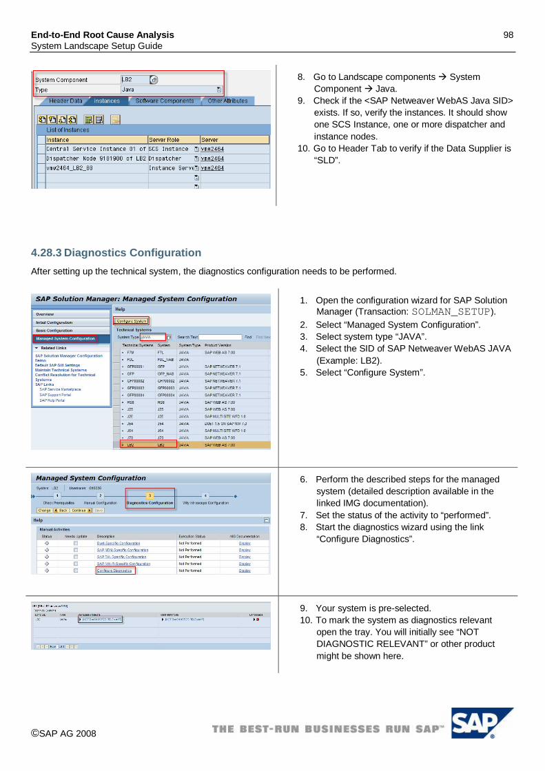
End-to-End Root Cause Analysis 98 System Landscape Setup Guide
©SAP AG 2008
8. Go to Landscape components System Component Java.
9. Check if the <SAP Netweaver WebAS Java SID> exists. If so, verify the instances. It should show one SCS Instance, one or more dispatcher and instance nodes.
10. Go to Header Tab to verify if the Data Supplier is “SLD”.
4.28.3 Diagnostics Configuration After setting up the technical system, the diagnostics configuration needs to be performed.
1. Open the configuration wizard for SAP Solution Manager (Transaction: SOLMAN_SETUP).
2. Select “Managed System Configuration”. 3. Select system type “JAVA”. 4. Select the SID of SAP Netweaver WebAS JAVA
(Example: LB2). 5. Select “Configure System”.
6. Perform the described steps for the managed system (detailed description available in the linked IMG documentation).
7. Set the status of the activity to “performed”. 8. Start the diagnostics wizard using the link
“Configure Diagnostics”.
9. Your system is pre-selected. 10. To mark the system as diagnostics relevant
open the tray. You will initially see “NOT DIAGNOSTIC RELEVANT” or other product might be shown here.

End-to-End Root Cause Analysis 99 System Landscape Setup Guide
©SAP AG 2008
11. Unselect the “Not Diagnostic Relevant” checkbox
12. Select MFG EXECUTION 5.1 and SAP NETWEAVER 7.0 Product Versions. You may find other products as well listed, if those applications are deployed in the same server.
13. Select “Set”. 14. Select “Setup” to continue the setup.
15. For each instance you need to enter the system installation path (e.g. C:\usr\sap\<SID>) and select “Set”.
16. After entering the needed information, save the data and continue the setup.
4.29 SAP Talent OrgChart 1.1, 2.0 For SAP Talent OrgChart 1.1, 2.0 an automated creation of the technical system via the SLD is currently not supported. Therefore you have to create the technical system manually and afterwards run connect the managed system using the managed system wizard.

End-to-End Root Cause Analysis 100 System Landscape Setup Guide
©SAP AG 2008
4.29.1 Manual creation of technical system for SAP Talent OrgChart 1.1, 2.0
1. Open the system maintenance application from the common tasks area of the “Root Cause Analysis” Workcenter (Transaction: SOLMAN_WORKCENTER).
2. Select “Create”.

End-to-End Root Cause Analysis 101 System Landscape Setup Guide
©SAP AG 2008
3. Enter a System ID for your SAP Talent OrgChart (TO) into the field “Technical System”, select type “MS .Net” and enter a description.
4. Select “Save”.
5. Select “Add Main Instance”. 6. Select the Product Version specific to your
installation. Example: “SAP TALENT ORGCHART 1.1” Main Instance “Org Chart”.
7. Select the Product Version “MS IIS 6.0” Main Instance “MS IIS”.
8. Select the Product Version “MSFT .NET 2.0” Main Instance “MSFT .Net Framework”.
9. Flag the System as “Production”. 10. Select “Save”.
11. Select Tab “Instances”. 12. Enter the TO System Instances, the Server and
the corresponding Operating System and its version. For the instance naming convention we recommend the following: <server>_<SID>_<#>.
13. If you cannot select the appropriate server from the value help, create a new server using the button “New Server”.
14. Select tab “Database”. 15. Enter the TO Server Database via the value help
or create a new database and select “Save”.

End-to-End Root Cause Analysis 102 System Landscape Setup Guide
©SAP AG 2008
4.29.2 Diagnostics Configuration After setting up the technical system, the diagnostics configuration needs to be performed.
1. Open the configuration wizard for SAP Solution Manager (Transaction: SOLMAN_SETUP).
2. Select “Managed System Configuration”. 3. Select system type “MS_.NET”. 4. Select system specific to your installation.
Example: SAP TALENT ORGCHART 1.1 System (TO).
5. Select “Configure System”.
6. Perform the described steps for the managed system of type TO (detailed description available in the linked IMG documentation).
7. Set the status of the activity to “performed”. 8. Start the diagnostics wizard using the link
“Configure Diagnostics”.
9. Your system is pre-selected. 10. To mark the system as diagnostics-relevant
open the tray.

End-to-End Root Cause Analysis 103 System Landscape Setup Guide
©SAP AG 2008
11. Unselect the checkbox. 12. Select MS IIS 6.0, MSFT .NET 2.0 and SAP
TALENT ORGCHART 1.1 or 2.0 Product Versions based on your installation.
13. Select “Set”. 14. Select “Setup” to continue the setup.
15. For each instance you need to enter the system installation path (e.g. D:\Program Files\Nakisa\) or D:\Program Files\Nakisa2.0\ based on your installation ) and select “Set”.
16. After entering the needed information, save the data and continue the setup.
4.29.3 Configuration on managed system After setting up the SAP Talent OrgChart system using the managed system wizard, managed system needs to be configured with Wily Introscope .NET Agent. Please follow the below mentioned guidelines for the same. To switch on reporting of SAP Talent OrgChart Server specific Wily Introscope metrics:
Install Wily Introscope .NET Agent as per the SAP Note 1126554. Restart the IIS Server.
4.30 SAP Talent Viewing 1.1, 2.0 For SAP Talent Viewing 1.1, 2.0 an automated creation of the technical system via the SLD is currently not supported. Therefore you have to create the technical system manually and afterwards run connect the managed system using the managed system wizard.

End-to-End Root Cause Analysis 104 System Landscape Setup Guide
©SAP AG 2008
4.30.1 Manual creation of technical system for SAP Talent Viewing 1.1, 2.0
1. Open the system maintenance application from the common tasks area of the Root Cause Analysis Workcenter (Transaction: SOLMAN_WORKCENTER).
2. Select “Create”.

End-to-End Root Cause Analysis 105 System Landscape Setup Guide
©SAP AG 2008
3. Enter a System ID for your SAP Talent Viewing (TV) into the field “Technical System”, select type “MS .Net” and enter a description.
4. Select “Save”.
5. Select “Add Main Instance”. 6. Select the Product Version specific to your
installation. Example: “SAP TALENT VIEWING 1.1” Main Instance “Org Chart”.
7. Repeat the above step to add “Succession Planning” for the above Product Version.
8. Select the Product Version “MS IIS 6.0” Main Instance “MS IIS”.
9. Select the Product Version “MSFT .NET 2.0” Main Instance “MSFT .Net Framework”.
10. Flag the System as “Production”. 11. Select “Save”.
12. Select Tab “Instances”. 13. Enter the System Instances, the Server and the
corresponding Operating System and its version. For the instance naming convention we recommend the following: <server>_<SID>_<#>.
14. If you cannot select the appropriate server from the value help, create a new server using the button “New Server”.
15. Select Tab “Database”. 16. Enter the TV Server Database via the value help
or create a new database and select “Save”.

End-to-End Root Cause Analysis 106 System Landscape Setup Guide
©SAP AG 2008
4.30.2 Diagnostics Configuration After setting up the technical system, the diagnostics configuration needs to be performed.
1. Open the configuration wizard for SAP Solution Manager (Transaction: SOLMAN_SETUP).
2. Select “Managed System Configuration”. 3. Select system type “MS_.NET”. 4. Select the system specific to your installation.
Example: SAP TALENT VIEWING 1.1 (Example: TV).
5. Select “Configure System”.
6. Perform the described steps for the managed system of type TV (detailed description available in the linked IMG documentation).
7. Set the status of the activity to “performed”. 8. Start the diagnostics wizard using the link
“Configure Diagnostics”.
9. Your system is pre-selected. 10. To mark the system as diagnostics-relevant
open the tray.
11. Unselect the checkbox. 12. Select MS IIS 6.0, MSFT .NET 2.0 and SAP
TALENT VIEWING 1.1 Product Versions. 13. Select “Set”. 14. Select “Setup” to continue the setup.

End-to-End Root Cause Analysis 107 System Landscape Setup Guide
©SAP AG 2008
15. For each instance you need to enter the system installation path (Example: D:\Program Files\Nakisa\) and select “Set”.
16. After entering the needed information, save the data and continue the setup.
4.30.3 Configuration on managed system After setting up the SAP Talent Viewing system using the managed system wizard, managed system needs to be configured with Wily Introscope .NET Agent. Please follow the below mentioned guidelines for the same. To switch on reporting of SAP Talent Viewing Server specific Wily Introscope metrics:
Install Wily Introscope .NET Agent as per the SAP Note 1126554. Restart the IIS Server.
4.31 SAP Talent Planning 1.1, 2.0 For SAP Talent Planning 1.1, 2.0 an automated creation of the technical system via the SLD is currently not supported. Therefore you have to create the technical system manually and afterwards run connect the managed system using the managed system wizard.

End-to-End Root Cause Analysis 108 System Landscape Setup Guide
©SAP AG 2008
4.31.1 Manual creation of technical system for SAP Talent Planning 1.1, 2.0
1. Open the system maintenance application from the common tasks area of the “Root Cause Analysis” Workcenter (Transaction: SOLMAN_WORKCENTER).

End-to-End Root Cause Analysis 109 System Landscape Setup Guide
©SAP AG 2008
2. Select “Create”.
3. Enter a System ID for your SAP Talent (TVN) into the field “Technical System”, select type “MS .Net” and enter a description.
4. Select “Save”.
5. Select “Add Main Instance”. 6. Select the Product Version specific to your
installation. Example: “SAP TALENT PLANNING 1.1” Main Instance “HCM Dashboard”.
7. Repeat the above step to add “Org Chart”, “Org Modeler” and “Succession Planning” for the above Product Version.
8. Select the Product Version “MS IIS 6.0” Main Instance “MS IIS”.
9. Select the Product Version “MSFT .NET 2.0” Main Instance “MSFT .Net Framework”.
10. Flag the System as “Production”. 11. Select “Save”.

End-to-End Root Cause Analysis 110 System Landscape Setup Guide
©SAP AG 2008
12. Select Tab “Instances”. 13. Enter the TVN System Instances, the Server and
the corresponding Operating System and its version. For the instance naming convention we recommend the following: <server>_<SID>_<#>.
14. If you cannot select the appropriate server from the value help, create a new server using the button.
15. Select Tab “Database”. 16. Enter the Server Database Example: TVN, via
the value help or create a new database and select “Save”.
4.31.2 Diagnostics Configuration After setting up the technical system, the diagnostics configuration needs to be performed.
1. Open the configuration wizard for SAP Solution Manager (Transaction: SOLMAN_SETUP).
2. Select “Managed System Configuration”. 3. Select system type “MS_.NET”. 4. Select the System specific to your installation.
Example: SAP TALENT PLANNING 1.1 System (TVN).
5. Select “Configure System”.

End-to-End Root Cause Analysis 111 System Landscape Setup Guide
©SAP AG 2008
6. Perform the described steps for the managed system of type MS.Net TVN (detailed description available in the linked IMG documentation).
7. Set the status of the activity to “performed”. 8. Start the diagnostics wizard using the link
“Configure Diagnostics”.
9. Your system is pre-selected. 10. To mark the system as diagnostics-relevant
open the tray.
11. Un-select the checkbox. 12. Select MS IIS 6.0, MSFT .NET 2.0, and SAP
TALENT PLANNING 1.1 - (choose the version specific to your installation) Product Versions.
13. Select “Set”. 14. Select “Setup” to continue the setup.
15. For each instance you need to enter the system installation path (e.g. D:\Program Files\Nakisa\) and select “Set”.
16. After entering the needed information, save the data and continue the setup.

End-to-End Root Cause Analysis 112 System Landscape Setup Guide
©SAP AG 2008
4.31.3 Configuration on managed system After setting up the SAP Talent Planning system using the managed system wizard, Managed system needs to be configured as follows: To switch on reporting of SAP Talent Planning Server specific Wily Introscope metrics:
Install Wily Introscope .NET Agent as per the SAP Note 1126554. Restart the IIS Server.
4.32 SAP Commodity SL 5.6/7.2 For SAP Commodity SL 5.6 (Native Java) the technical system has to be created manually and perform the managed system configuration using the Diagnostics setup wizard.
4.32.1 Manual creation of technical system for SAP Commodity SL 5.6/7.2
1. Open the System Landscape application. Solution Manager Transaction: SMSY
2. Go to Landscape components Server 3. Create the Server (Managed System /DB host
information) and input server details.

End-to-End Root Cause Analysis 113 System Landscape Setup Guide
©SAP AG 2008
4. Go to Landscape components Create Database (input Database specific information)
5. In the Server field input the Server as a reference. The server was created in the previous step
6. Select Unspecified Technical System Type and right click to Create New Technical System.
7. Once the Technical System is created choose Production check box on the Header data tab and fill the rest of the data.
8. Select the Database (Database has been created in previous step)
9. Input Instance and server Information on the Instances Tab of the Technical System. Instance name follows a specific format. <server name>_<system ID>. Example:USPHLVM1022_TNJ_00

End-to-End Root Cause Analysis 114 System Landscape Setup Guide
©SAP AG 2008
10. On the Software Components Tab of the Technical System select Commodity SL release specific software components. For Commodity SL 7.2 choose Software Component from the associated F4 input field help as shown in the screen. Similarly, For TPT Commodity SL 5.6 select from F4 input help on the Software Component input field.
11. Select Product Systems and right click Create New Product System.
12. Input Product System. Example: TNJ 13. Choose Product Commodity SL (for 7.2 release) 14. Or choose Product TPT Commodity SL (for 5.6
release) 15. Enter and continue.
16. Under Product Systems find the system created as follows.
17. For CSL 7.2 Find Commodity SL product 18. For CSL 5.6 Find TPT Commodity SL product 19. Select and expand the respective product as shown in the
screen. 20. Select and expand the Technical system associated. 21. Ensure the Header data tab has the Product version

End-to-End Root Cause Analysis 115 System Landscape Setup Guide
©SAP AG 2008
associated to it under Active Product Versions. Example: Commodity SL 7.2
22. Choose Product Instance Selection tab. 23. Select the fields: Relevant, Technical Assignment check
box ‘x’ for Commodity SL Native java Product. Instance. 24. Select Technical System that was defined as per the
above steps from the F4 Input Help. System Type will be automatically set to Unspecified. Example: TNJ
4.32.2 Diagnostics Configuration After setting up the technical system, the diagnostics configuration needs to be performed. Please note that the user interface to perform the diagnostics configuration may vary slightly from the below screen captures depending on the Solution Manager Release and support pack your installation is based on.
1. Open the configuration wizard for SAP Solution Manager (Transaction: SOLMAN_SETUP)
2. Select Managed System Configuration 3. Select system type “UNSPECIFIC” 4. Select the SID of CSL UNSPECIFIED SYSTEM
(Example: TNJ) 5. Select Configure System

End-to-End Root Cause Analysis 116 System Landscape Setup Guide
©SAP AG 2008
6. Perform the described steps for the managed system (Detailed description is available in the linked IMG documentation. Following steps below assume that Initial & Basic configuration is completed.)
7. Start the diagnostics wizard using the link Configure Diagnostics from 3rd step (Diagnostics Configuration) of the Managed System Configuration.
8. Click on Open Url link from the Navigation column.
9. Setup Wizard page Identify & select your system. Example: TNJ of Type UNSPECIFIC.
10. Expand the System (Example: TNJ) Expand Managed Products column.
11. Uncheck [Not Diagnostics Relevant] check box. 12. Select SAP Commodity SL Product (specific to your
installation). 13. Select “Set”. 14. Select “Setup” to continue the setup.
15. Expand Details Ensure the agent has been assigned 16. Wily EM host/port are set 17. System Install Path is input. Example:
D:\CSL7_1\SL_7_1\ 18. Expand Software components Paths (optional) window
input the path specific to your installation. 19. Select “Set”. 20. Ensure the checkbox is ‘x’ 21. Select “Next” to continue the setup.

End-to-End Root Cause Analysis 117 System Landscape Setup Guide
©SAP AG 2008
22. In the last step, status of green indicators will show up as successful completion. Yellow indicator may signal some warnings exist.
4.33 SAP eLearning Adobe Connect 6.02 For SAP eLearning Adobe Connect, an automated creation of the technical system via the SLD is currently not supported. Therefore you have to create the technical system manually and afterwards connect the managed system using connect managed system wizard.
4.33.1 Manual creation of technical system for SAP elearning Adobe Connect
1. Open the “System Maintenance” application from the common tasks area of the “Root Cause Analysis” Workcenter (Transaction: SOLMAN_WORKCENTER).
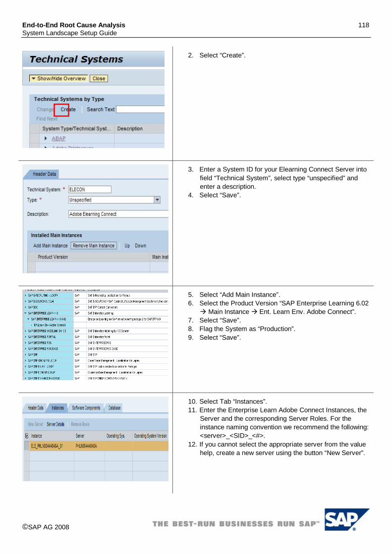
End-to-End Root Cause Analysis 118 System Landscape Setup Guide
©SAP AG 2008
2. Select “Create”.
3. Enter a System ID for your Elearning Connect Server into field “Technical System”, select type “unspecified” and enter a description.
4. Select “Save”.
5. Select “Add Main Instance”. 6. Select the Product Version “SAP Enterprise Learning 6.02
Main Instance Ent. Learn Env. Adobe Connect”. 7. Select “Save”. 8. Flag the System as “Production”. 9. Select “Save”.
10. Select Tab “Instances”. 11. Enter the Enterprise Learn Adobe Connect Instances, the
Server and the corresponding Server Roles. For the instance naming convention we recommend the following: <server>_<SID>_<#>.
12. If you cannot select the appropriate server from the value help, create a new server using the button “New Server”.

End-to-End Root Cause Analysis 119 System Landscape Setup Guide
©SAP AG 2008
13. Make sure the software components are correct.
14. Select tab “Database”. 15. You are not able to create Database server here. You
have to use transaction code “SMSY” in ABAP stack to create Database and select E-Sourcing server. After Database is created, you should be able to see Database information after you select “Database”.
4.33.2 Diagnostics Configuration After making sure that your SAP E-Sourcing system is correctly set up, you can proceed with the diagnostics configuration for you SAP E-Sourcing system.
1. Open the diagnostics setup application from the common tasks area of the “Root Cause Analysis” Workcenter (Transaction: SOLMAN_WORKCENTER).
2. Choose “Managed Systems”. 3. Choose “Setup Wizard”.

End-to-End Root Cause Analysis 120 System Landscape Setup Guide
©SAP AG 2008
4. Jump to the SID of your Elearning Adobe Connect.
5. Set the Elearning Adobe Connect as “Diagnostics Relevant”.
6. Start the Setup using the “Setup SID (PRODUCT)” button.
7. In the Setup Parameters step, ensure the following settings:
Select your Wily server. Please fill in n the System Install Path:
/breeze/ if your installation path is selected as this, otherwise enter your system installation path.
8. After this is done, continue with the setup.
4.34 SAP RA 2.0, 2.7 For SAP RA an automated creation of the technical system via the SLD is currently not supported. Therefore you have to create the technical system manually and afterwards run connect the managed system using the managed system wizard.

End-to-End Root Cause Analysis 121 System Landscape Setup Guide
©SAP AG 2008
4.34.1 Manual creation of technical system for SAP RA
1. Open the “System Maintenance” application from the common tasks area of the “Root Cause Analysis” Workcenter (Transaction: SOLMAN_WORKCENTER).
2. Select “Create”.
3. Enter a System ID for your RA Server into field “Technical System”, select type “unspecified” and enter a description.
4. Select “Save”.
5. Select “Add Main Instance”. 6. Select the Product Version “SAP Return Authorization”
“SAP Return Authorization 2.0” Main Instance “Express Return Server”.
7. Select “Save”. 8. Flag the system as “Production”. 9. Select “Save”.

End-to-End Root Cause Analysis 122 System Landscape Setup Guide
©SAP AG 2008
10. Select Tab “Instances”. 11. Enter the RA Instances, the Server and the corresponding
Server Roles. For the instance naming convention we recommend the following: <server>_<SID>_<#>.
12. If you cannot select the appropriate server from the value help, create a new server using the button “New Server”.
13. Select Tab “Database”. 14. You are not able to create Database server here. You
have to use transaction code SMSY in ABAP stack to create Database and select RA server. After Database is created, you should be able to see Database information after you select “Database”.

End-to-End Root Cause Analysis 123 System Landscape Setup Guide
©SAP AG 2008
4.34.2 Diagnostics Configuration After making sure that your SAP RA system is correctly set up, you can proceed with the diagnostics configuration for your SAP RA system.
1. Open the “Diagnostics Setup” application from the common tasks area of the “Root Cause Analysis” Workcenter (Transaction: SOLMAN_WORKCENTER).
2. Choose “Managed Systems”. 3. Choose “Setup Wizard”.
4. Jump to the SID of your RA.

End-to-End Root Cause Analysis 124 System Landscape Setup Guide
©SAP AG 2008
5. Set the RA as “Diagnostics Relevant”. 6. Start the Setup using the “Setup SID (PRODUCT)”
button.
7. In the Setup Parameters step, ensure the following settings:
Select your Wily server. Please fill in the System Install Path:
/SAP/ if your installation path is selected as this, otherwise enter your system installation path.
8. After this is done, continue with the setup.

End-to-End Root Cause Analysis 125 System Landscape Setup Guide
©SAP AG 2008
9. Select Wily server. 10. After successful setup you should see green traffic
light.
4.35 SAP ALM by SAP and Sungard 6.0, 6.1, 7.0 For SAP ALM by Sungard an automated creation of the technical system via the SLD is currently not supported. Therefore you have to create the technical system manually and afterwards connect the managed system using the managed system setup wizard. Attention: Before continuing, implement SAP Note 1290589.
4.35.1 Manual creation of technical system for SAP ALM by Sungard

End-to-End Root Cause Analysis 126 System Landscape Setup Guide
©SAP AG 2008
1. Open the “System Maintenance” application from the common tasks area of the “Root Cause Analysis” Workcenter (Transaction: SOLMAN_WORKCENTER).
2. Select “Create”.

End-to-End Root Cause Analysis 127 System Landscape Setup Guide
©SAP AG 2008
3. Enter a System ID for your SAP ALM by Sungard (ALM) into the field “Technical System”, select type “MS .Net” and enter a description.
4. Save your entries.
5. Select “Add Main Instance”. 6. Select the Product Version, e.g. “Focus ALM 6.0” Main
Instance “Banking Service SUNGRD”. 7. Select the Product Version “MS IIS 6.0” Main Instance
“MS IIS”. 8. Select the Product Version “MSFT .NET 2.0” Main
Instance “MSFT .Net Framework”. 9. Flag the System as “Production”. 10. Save your entries. Attention: For the Product Version “Focus ALM 7.0”, do not additionally select any Product Version MS IIS and do select the Product Version “MSFT .NET 3.5” instead of “MSFT .NET 2.0”.
11. Select Tab “Instances”. 12. Enter the ALM System Instances, the Server and the
corresponding Operating System and its version. For the instance naming convention we recommend the following: <server>_<SID>_<#>.
13. If you cannot select the appropriate server from the value help, create a new server using the “New Server” dialog.

End-to-End Root Cause Analysis 128 System Landscape Setup Guide
©SAP AG 2008
14. Select Tab “Database”. 15. Enter the ALM Server Database via the value help or create
a new database and save your entries with “Save”.
4.35.2 Diagnostics Configuration After setting up the technical system, the diagnostics configuration needs to be performed.
1. Open the configuration wizard for SAP Solution Manager (Transaction: SOLMAN_SETUP).
2. Select “Managed System Configuration”. 3. Select system type “MS_.NET”. 4. Select the previously created Focus ALM 6.0 System
(Example: ALM). 5. Select “Configure System”.
6. Perform the described steps for the managed system (detailed description available in the linked IMG documentation).
7. Set the status of the activity to “performed”. 8. Start the diagnostics wizard using the link “Configure
Diagnostics”.

End-to-End Root Cause Analysis 129 System Landscape Setup Guide
©SAP AG 2008
9. Your system is pre-selected. 10. Open the tray to mark the system as diagnostics-relevant.
11. Unselect the checkbox. 12. Select MS IIS 6.0, MSFT .NET 2.0 and Focus ALM 6.0
Product Versions (in the example of SAP ALM by SAP and Sungard 6.0).
13. Select “Set”. 14. Select “Setup” to continue the setup.
15. For each instance you need to enter the system installation directory (e.g. D:\) and select “Set”.
16. After entering the needed information, save the data and continue the setup.
4.35.3 CA Wily Introscope Configuration After setting up Solution Manager Diagnostics for the SAP ALM by Sungard system using the managed system setup wizard, CA Wily Introscope .NET support needs to be configured. Install and configure the CA Wily Introscope .NET agent on the managed system as per SAP Note 1126554.
4.36 Questra IDM 5.2S
4.36.1 Sending Data to System Landscape Directory The SLD Data Supplier is configured to stream its system landscape information to the central SLD. As Questra IDM 5.2S is hosted on the SAP J2EE Engine, the SLD Data Supplier service of the SAP J2EE Engine needs to be

End-to-End Root Cause Analysis 130 System Landscape Setup Guide
©SAP AG 2008
configured to report the appropriate data to the central SLD. Please refer to the following information to publish system landscape information to the SLD:
SAP Note: 1147499 – Connection to the System Landscape Directory. SAP Note: 673144 – J2EE Engine Registration in the System Landscape Directory. SAP Help:
http://help.sap.com/saphelp_nw70/helpdata/EN/42/e33ae230ba3ee2e10000000a1553f6/frameset.htm
4.36.2 Configuring Technical System for Questra IDM 5.2S
1. Open the System Landscape application (Transaction: SMSY).
2. Go to “Landscape components” “Server”. 3. Check if the <server name> exists. If so, verify server
details. 4. Go to Header tab to verify if the Data Supplier is “SLD”.

End-to-End Root Cause Analysis 131 System Landscape Setup Guide
©SAP AG 2008
5. Go to “Landscape components” “Database”. 6. Check if the <SAP Netweaver WebAS Java SID> exists. If
so, verify Database. 7. Go to Header tab to verify if the Data Supplier is “SLD”.
8. Go to “Landscape components” “System Component” “Java”.
9. Check if the <SAP Netweaver WebAS Java SID> exists. If so, verify the instances. It should show one SCS Instance, one or more dispatcher and instance nodes.
10. Go to Header tab to verify if the Data Supplier is “SLD”.

End-to-End Root Cause Analysis 132 System Landscape Setup Guide
©SAP AG 2008
4.36.3 Diagnostics Configuration After setting up the technical system, the diagnostics configuration needs to be performed.
1. Open the configuration wizard for SAP Solution Manager (Transaction: SOLMAN_SETUP).
2. Select “Managed System Configuration”. 3. Select system type “JAVA”. 4. Select the SID of SAP Netweaver WebAS JAVA
(Example: LB2). 5. Select “Configure System”.
6. Perform the described steps for the managed system (detailed description available in the linked IMG documentation).
7. Set the status of the activity to “performed”. 8. Start the diagnostics wizard using the link Configure
Diagnostics.
9. Your system is pre-selected. 10. To mark the system as diagnostics relevant open the tray.
You will initially see “Not Diagnostic Relevant” or other product might be shown here.
11. Unselect the “Not Diagnostic Relevant” checkbox. 12. Select Questra IDM 5.2S and SAP WEB AS 7.0 Product
Versions. You may find other products as well listed, if those applications are deployed in the same server, as in this case an SAP Price and Margin Management product.
13. Select “Set”. 14. Select “Setup” to continue the setup.

End-to-End Root Cause Analysis 133 System Landscape Setup Guide
©SAP AG 2008
15. For each instance you need to enter the system installation path (e.g. C:\usr\sap\<SID>) and select “Set". If necessary, enter the software component paths. For Questra IDM 5.2S, no entry is necessary here.
16. After entering the needed information, save the data and continue the setup.
4.37 SAP Reach Compliance 1.1 This chapter describes the steps to setup a managed system SAP Reach Compliance 1.1. Table below summarizes the five deployment scenarios you can encounter.
Scenarios Double Stack SAP Basis SAP J2EE 1 SAP J2EE 2 SAP Basis SAP J2EE ERP 6.0 Scenario 1
REACH (Abap) ERP 6.0 (EH&S)
REACH (Portal) REACH (J2EE) SAP Portal (*)
ERP 6.0 Scenario 2 REACH (Abap)
ERP 6.0 (EH&S)
REACH (Portal) REACH (J2EE) SAP Portal (*)
ERP 6.0 Scenario 3
SAP REACH (Abap)
ERP 6.0 (EH&S)
REACH (Portal) SAP Portal (*) REACH (J2EE)
ERP 2004 Scenario 1
REACH (Abap) ERP 2004 (EH&S)
REACH (Portal) REACH (J2EE) SAP Portal (*)
ERP 2004 Scenario 2
SAP REACH (Abap)
ERP 2004 (EH&S)
SAP REACH (Portal) SAP Portal (*) SAP REACH (J2EE)
The entry point for the SAP Reach Compliance system setup is the transaction SOLMAN_SETUP on Solution Manager. From here, you’ll find the complete guided procedure to setup your managed system (each step is extensively described in the inline help). In the following, we focus only on the steps specific to a SAP Reach Compliance system. As this product is an add-on to SAP ERP which includes an Abap Stack and one or two Java stacks, you’ll have to setup the corresponding technical systems.

End-to-End Root Cause Analysis 134 System Landscape Setup Guide
©SAP AG 2008
4.37.1 Check solution landscape If the prerequisites are met and Solution Manager as well as the managed system have been properly configured, technical landscape is collected from SLD infrastructure then fetch by Solution Manager. As these tasks are performed by scheduled jobs, it might take some time before the landscape is visible in Solution Manager.
1. Open Solution Manager System Landscape (Transaction: SMSY).
2. Select “Landscape Components”. 3. Check that the Server is there. 4. Check that the Database is there. 5. Check that there are System Components of type “Java”
corresponding to the J2EE part of the landscape (one or two depending on the deployment scenario).
6. Check that there is a System under product “SAP REAH COMPLIANCE” for the ERP part of the landscape.
7. Check that Java System Component (can be the same J2EE depending on the deployment scenario) is assigned to Main instances “Portal Content” and “TDAG UI for Reach”.

End-to-End Root Cause Analysis 135 System Landscape Setup Guide
©SAP AG 2008
8. Check that product “ERP” is part of the possible product versions.
9. Check that Java System Component (can be the same J2EE depending on the deployment scenario) is assigned to Main Instances “SAP NW – Applic. Server Java” and “SAP NW – Enterprise Portal”.

End-to-End Root Cause Analysis 136 System Landscape Setup Guide
©SAP AG 2008
4.37.2 ABAP technical system setup
1. Open the configuration wizard for SAP Solution Manager (Transaction: SOLMAN_SETUP).
2. Select “Managed System Configuration”. 3. Select the Abap technical system. 4. Select relevant Abap client. 5. Select “Configure System”. 6. Follow the guided procedure.
7. You are at the step 4 of the guided procedure “Diagnostics Configuration” for the Abap technical system.
8. During this step, you do the activity “Configure Diagnostics”.
9. Select “Configure Diagnostics” in the table.
10. Technical system is pre-selected. 11. Mark the technical system as “relevant” by de-selecting the
check box “Not Diagnostics Relevant”. 12. In case of an ERP 6.0 scenario, select in the list of product
versions “SAP ERP 6.0” and “SAP REACH COMPLIANCE 1.1” (by holding the Ctrl key).
13. In case of ERP 2004 scenario, select in the list of product versions “SAP ERP 2004” and “SAP REACH COMPLIANCE 1.1” (by holding the Ctrl key).
14. In case of an ERP 6.0 scenario, select in the list of Main Instances “TDAG for Reach ERP 2005” and “ECC Server”.
15. In case of an ERP 2004 scenario, select in the list of Main Instances “TDAG for Reach ERP 2004” and “ECC Server”.
16. Select “Set”. 17. Select “Setup”. 18. Continue the Diagnostics setup. 19. Continue the guided procedure.

End-to-End Root Cause Analysis 137 System Landscape Setup Guide
©SAP AG 2008
4.37.3 Java technical system setup
1. Open the configuration wizard for SAP Solution Manager (Transaction: SOLMAN_SETUP).
2. Select “Managed System Configuration”. 3. Select the Java technical system. 4. Select “Configure System”. 5. Follow the guided procedure.
6. You are at the step 4 of the guided procedure “Diagnostics Configuration” for the Java technical system.
7. During this step, you do the activity “Configure Diagnostics”.
8. Select “Configure Diagnostics” in the table.

End-to-End Root Cause Analysis 138 System Landscape Setup Guide
©SAP AG 2008
9. Technical system is pre-selected. 10. Mark the technical system as “relevant” by de-selecting the
check box “Not Diagnostics Relevant”. 11. In case of an ERP 6.0 scenario, select in the list of product
versions “SAP ERP 6.0” and “SAP REACH COMPLIANCE 1.1” (by holding the Ctrl key).
12. In case of ERP 2004 scenario, select in the list of product versions “SAP ERP 2004” and “SAP REACH COMPLIANCE 1.1” (by holding of the Ctrl key).
13. Select in the list of Main Instances “TDAG UI for Reach”, “SAP NW – Applic. Server Java” and “Portal Content”.
14. Select “Set”. 15. Select “Setup”. 20. Continue the Diagnostics setup. 16. Continue the guided procedure.
4.38 SAP Commodity SL (NW) 5.6/7.2 The SLD Data Supplier is configured to stream its system landscape information to the central SLD. As CSL 5.6/7.2 is hosted on the SAP J2EE Engine, the SLD Data Supplier service of the SAP J2EE Engine needs to be configured to report the appropriate data to the central SLD. Please refer to the following information to publish system landscape information to the SLD.
SAP Note: 1147499 – Connection to the System Landscape Directory SAP Note: 673144 – J2EE Engine Registration in the System Landscape Directory SAP Note: 1455248 – Wily Introscope for Commodity SL Native Java Servers SAP Note: 1423145 – CCMS Monitoring Setup for Commodity SL using GRMG SAP Help:
http://help.sap.com/saphelp_nw70/helpdata/EN/42/e33ae230ba3ee2e10000000a1553f6/frameset.htm

End-to-End Root Cause Analysis 139 System Landscape Setup Guide
©SAP AG 2008
4.38.1 Configuring Technical System for TPT Commodity SL (NW)
1. Open the System Landscape application (Transaction: SMSY)
2. Go to Landscape components Server 3. Check if the <server name> exists. If so, verify server
details. 4. Go to Header Tab to verify if the Data Supplier is “SLD”.
5. Go to Landscape components Database 6. Check if the <SAP Netweaver WebAS Java SID> exists. If
so, verify Database 7. Go to Header Tab to verify if the Data Supplier is “SLD”.

End-to-End Root Cause Analysis 140 System Landscape Setup Guide
©SAP AG 2008
8. Go to Landscape Components “Product Systems” (also formally known as “Systems”) and expand.
9. For CSL 5.6 find the Product System “TPT COMMODITY SL” and expand.
10. For CSL 7.2 find the Product System “COMMODITY SL” and expand.
11. Go to Header Data tab and ensure the Active Product versions.
12. Based on your specific CSL installation, ensure CSL product release & Netweaver system. Example: Commodity SL 7.1 & SAP Netweaver 7.0
13. Go to Product Instance Selection tab. 14. Ensure Commodity SL Product Instance is checked as
“Relevant”, Technical System is input and corresponding System type is set to “Java”.

End-to-End Root Cause Analysis 141 System Landscape Setup Guide
©SAP AG 2008
15. Go to Landscape Components Technical Systems (also formally known as System Components) Java
16. Check if the <SAP Netweaver WebAS Java SID> exists. If so, verify the instances. It should show one SCS Instance, one or more dispatcher and instance nodes.
17. Go to Header Tab to verify if the Data Supplier is “SLD”.
18. Go to Software Components Tab. 19. Ensure the CSL Software components are listed specific to
the CSL installation.
20. If for some reason, you do not find relevant CSL specific software components then you can manually add them by switching to Display <> Change mode.
21. If Step 20 is true in your case, continue with these steps 22 – 24, otherwise continue with the Diagnostics Configuration.
22. Select “of Prod. Instance” command button from the Software Components Tab in Edit mode.
23. A dialog prompts you to input the product you are looking. Example: for CSL 7.2 release – find Product: COMMODITY SL. For CSL 5.6 release – find Product: TPT COMMODITY SL.
24. Choose appropriate Product version specific to your installation.
25. Choose Prod. Instance as “COMMODITY SL”.

End-to-End Root Cause Analysis 142 System Landscape Setup Guide
©SAP AG 2008
4.38.2 Diagnostics Configuration After setting up the technical system, the diagnostics configuration needs to be performed.
1. Open the configuration wizard for SAP Solution Manager (Transaction: SOLMAN_SETUP)
2. Select Managed System Configuration 3. Select system type JAVA 4. Select the SID of SAP Netweaver WebAS JAVA (Example:
LB2) 5. Select Configure System
6. Perform the described steps for the managed system (detailed description available in the linked IMG documentation)
7. Set the status of the activity to performed 8. Start the diagnostics wizard using the link Configure
Diagnostics.
9. Your system is pre-selected. 10. To mark the system as diagnostics relevant open the tray.
You will initially see “NOT DIAGNOSTIC RELEVANT” or other product might be shown here.
11. Unselect the “Not Diagnostic Relevant” checkbox 12. Select CSL 5.6 or 7.2* and SAP Netweaver 7.0 Product
Version*. *(Choose release specific to your installation)
13. Select Set 14. Select Setup to continue the setup

End-to-End Root Cause Analysis 143 System Landscape Setup Guide
©SAP AG 2008
15. For each instance you need to enter the CSL system installation path (e.g. C:\usr\sap\<SID>) and select set. If necessary, enter the software component paths.
16. After entering the needed information, save the data and continue the setup.
17. In the last step, status of green indicators will show up as successful completion. Yellow indicator may signal some warnings exist.
4.39 SAP BCM 6.0 For SAP BCM, an automated creation of the technical system via the SLD is currently not supported. Therefore you have to create the technical system manually and afterwards run connect the managed system using the managed system wizard.
4.39.1 Manual creation of technical system for SAP BCM 6.0
1. Open the “System Maintenance” application from the common tasks area of the “Root Cause Analysis” Workcenter (Transaction: SOLMAN_WORKCENTER).

End-to-End Root Cause Analysis 144 System Landscape Setup Guide
©SAP AG 2008
2. Select “Create”.
3. Enter a System ID for your BCM technical system into field “Technical System”, select type “unspecified” and enter a description.
4. Select “Save”.
5. Select “Add Main Instance”. 6. Select the Product Version “SAP BCM Software 6.0”
Main Instance “BCM Server” and click OK. 7. Repeat step 5 to 6 and add the following two main
instances: MS IIS 6.0 MS IIS MSFT .NET 2.0 MSFT .NET Framework
8. Flag the System as “Production”. 9. Select “Save”.
10. Select Tab “Instances”. 11. Enter the BCM Instances. For each server, one instance
entry needs to be maintained here. For the instance naming convention, we recommend the following: <server>_<SID>_<#>.
12. If you cannot select the appropriate server from the value help, create a new server using the button “New Server”.

End-to-End Root Cause Analysis 145 System Landscape Setup Guide
©SAP AG 2008
13. Select tab “Database”. 14. You can’t create a Database server here unless you flag
the box “Maintain Database Use”. Create CPM and CEM database for your BCM system first.
15. Select “Save”.
4.39.2 Update Component Template for BCM Please follow SAP OSS Note 1288773: SMD: Change Reporting for SAP BCM 5.5 and 6.0 to update the component template for BCM in your Solution Manager.
4.39.3 Diagnostics Configuration After making sure that your SAP BCM system is correctly set up, you can proceed with the diagnostics configuration for you SAP BCM system.
1. Open the diagnostics setup application from the common tasks area of the “Root Cause Analysis” Workcenter (Transaction: SOLMAN_WORKCENTER).
2. Choose “Managed Systems”. 3. Choose “Setup Wizard”.

End-to-End Root Cause Analysis 146 System Landscape Setup Guide
©SAP AG 2008
4. Set the BCM as “Diagnostics Relevant” and select all the products listed there.
5. Click “Set”. 6. Start the setup using the “Setup <SID> (Type)” button.

End-to-End Root Cause Analysis 147 System Landscape Setup Guide
©SAP AG 2008
7. In the Setup Parameters step, ensure the following settings for each server entry:
Select your Wily server. Please fill in the System Install Path. By default, it
is “C:\Program Files\Wicom\”. 8. Expand the “Software components paths (optional)” tray
and specify the path for IIS and .NET Framework. By default, both of them are “C:\Windows\”.
9. After this is done, continue with the setup. After successful setup you should see green traffic light.
4.40 SAP BusinessObjects Enterprise XI R2 For BusinessObjects Enterprise XI R2 an automated creation of the technical landscape via SLD is not supported. Therefore you have to create the technical landscape manually and afterwards perform the Diagnostics Configuration for the BOE system using the “Diagnostics Setup” wizard.
4.40.1 Creation of Technical System for BOE platform
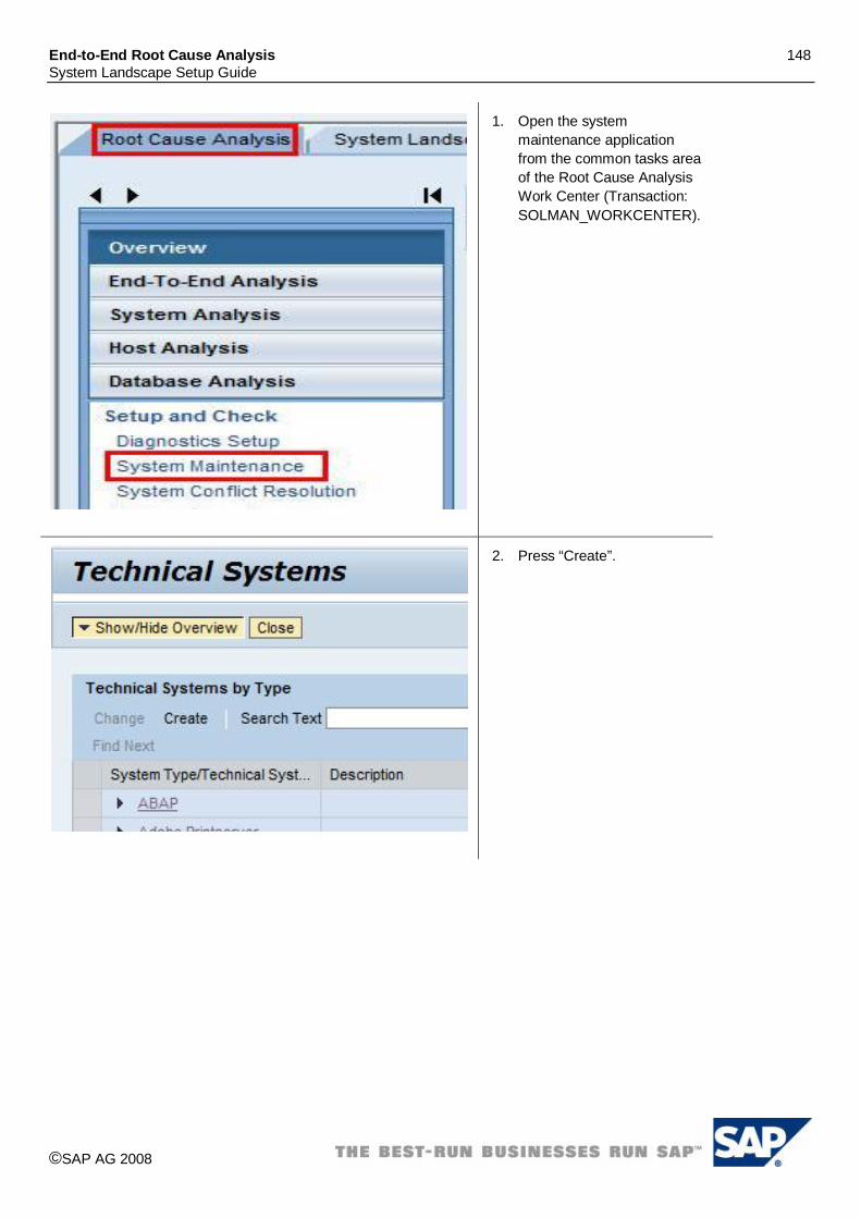
End-to-End Root Cause Analysis 148 System Landscape Setup Guide
©SAP AG 2008
1. Open the system maintenance application from the common tasks area of the Root Cause Analysis Work Center (Transaction: SOLMAN_WORKCENTER).
2. Press “Create”.

End-to-End Root Cause Analysis 149 System Landscape Setup Guide
©SAP AG 2008
3. Enter a System ID into field “Technical System”, select type “Unspecified” and enter a description.
Please note: - Business Objects
Enterprise does not have a System ID concept, however, in order to identify the system uniquely in Solution Manager, you need to make up and enter a unique system ID here. Usually a Technical System is identified by three letters in upper case (long SID can be longer).
4. Press “Save”.
5. Press “Add Product Instance”.
6. Select the Product Version “BOBJ ENTERPRISE XI R2”.
7. Select Product Instance “CENTRAL MANAGEMENT SERVER”.
8. Repeat steps 5, 6 & 7 above for the following Product Instances:
i. CRYSTAL REPORTS SERVER ii. DESKTOP INTELLIGENCE
SERVER iii. EVENT SERVER iv. INPUT FILE REPOSITORY
SERVER v. JOB SERVER vi. MULTIDIMENSIONAL ANALY.
SERVER vii. OUTPUT FILE REPOSITORY
SERVER viii. REPORT APPLICATION
SERVER ix. SEARCH SERVER x. WEB INTELLIGENCE SERVER
9. Press “Save”. 10. Flag the System as
“Production” in case of a

End-to-End Root Cause Analysis 150 System Landscape Setup Guide
©SAP AG 2008
production system. 11. Press “Save”.
12. Select Tab “Instances”. 13. Enter one instance per host
in the cluster. For the instance naming convention, we recommend the following: BOE _<server> (screenshot is inverted).
14. If you cannot select the appropriate server from the value help, create a new server using the button.
15. Select Tab “Database”. 16. Enter the Central Repository
Database via the value help if the database was previously created or create a new database and select “Save”. It is recommended to use the same ID as was chosen for the Business Objects system.

End-to-End Root Cause Analysis 151 System Landscape Setup Guide
©SAP AG 2008
4.40.2 Creation of Technical System for BOE Web Application Server
1. Call transaction “SMSY”. 2. Right-click on Server. 3. Check that a server name
exists for each host where a WAS is installed. If yes, you do not need to create it again, go directly to step 9.
4. Select “Create New Server”.
5. Enter the server name where the WAS is installed.
6. Press Save.
7. Maintain at least the fields “Fully-Qualified Host Name” and “IP-Address”.
8. Select “Save”.
9. Right-click on Technical Systems.
10. Select “Create New Technical System”.
11. Enter the System ID of the WAS system as Technical System name.
Please note: - Business Objects
Enterprise does not have a System ID concept, however, in order to identify the system

End-to-End Root Cause Analysis 152 System Landscape Setup Guide
©SAP AG 2008
uniquely in Solution Manager, you need to make up and enter a unique system ID here. Usually a Technical System is identified by three letters in upper case (long SID can be longer).
12. Select type “Unspecified”. 13. You can leave the field
Installation Number free. 14. Select “Save”.
15. Select tab “Header Data” 16. Select Flag “Production” in
case it is a production system.
17. Select tab “Instances” 18. Repeat the following for each
server (host) where WAS Servers are installed:
19. Add a new line. 20. Select the Server in field
“Server”. 21. Maintain the Instance Names
according to the following naming convention: WAS_<Server Name>
22. Select tab “Software Components”.
23. Select button: “of Prod. Instance”
24. Select Product Version “BOBJ Enterprise XI R2”
25. Select Product Instance “BOE WEB APPLICATION”.
26. Select “Continue (Enter)”

End-to-End Root Cause Analysis 153 System Landscape Setup Guide
©SAP AG 2008
4.40.3 Installation of Diagnostics Agent If not already done so, SAP Host Control and a Diagnostics Agent needs to be installed on all hosts where BOE is installed (including the host(s) where the customer database(s) are installed). Please refer to SAP Note 1234387.
4.40.4 Diagnostics Configuration After setting up the Technical System, the diagnostics configuration needs to be performed.
19. Open the configuration wizard for SAP Solution Manager (Transaction: SOLMAN_SETUP).
20. Select Managed System Configuration.
21. Select or enter system type UNSPECIFIC.
22. Select the previously created “SBOP Enterprise” Technical System (Example: BOE).
23. Press “Configure System”.
24. Perform the described steps for the managed system (detailed description available in the linked IMG documentation). The following steps are relevant:
xi. “Diagnostics Prerequisites” xii. “Install Diagnostics Agent xiii. ”Maintain SAP Router data” xiv. “Configure DBA Cockpit” xv. “Configure Diagnostics”
(see below) 25. Set the status of the
activity to “performed” when done.
26. Start the diagnostics wizard using the link Configure Diagnostics.

End-to-End Root Cause Analysis 154 System Landscape Setup Guide
©SAP AG 2008
27. Technical System is pre-selected.
28. Open the tray and mark the Technical System as relevant for diagnostics.
29. Select the following Product Instances relevant for diagnostics:
xvi. CENTRAL MANAGEMENT SERVER
xvii. CRYSTAL REPORTS SERVER xviii. DESKTOP INTELLIGENCE
SERVER xix. EVENT SERVER xx. INPUT FILE REPOSITORY
SERVER xxi. JOB SERVER xxii. MULTIDIMENSIONAL ANALY.
SERVER xxiii. OUTPUT FILE REPOSITORY
SERVER xxiv. REPORT APPLICATION
SERVER xxv. SEARCH SERVER xxvi. WEB INTELLIGENCE SERVER
30. Press “Set”. 31. Press “Setup” in the bottom
of the page.

End-to-End Root Cause Analysis 155 System Landscape Setup Guide
©SAP AG 2008
32. For each server instance perform step 15 to 19.
33. Expand the details tray. 34. Check that SMD Agent is
selected properly. 35. Select the relevant Wily
Introscope Manager. 36. Enter the installation path of
the system. Example: C:\Program Files\Business
Objects\BusinessObjects Enterprise 11.5\. As a landmark, just under the installation directory, you should find the directory “logging” on Windows and directory “bobje” on Unix like OS.
37. Press “Set”.
20. If there is no load balancer, enter the host and the port of the Web Application Server.
21. Select “Save” icon.
22. Select all the instances to setup.
23. Press “Next”.

End-to-End Root Cause Analysis 156 System Landscape Setup Guide
©SAP AG 2008
24. Press “Setup”. 25. Wait the end of the setup
tasks.
4.40.5 Diagnostics Configuration for Web Application Server You need to follow the same steps described for the BOE Technical System (previous chapter “Diagnostics Configuration”). Differences are listed below:
Step 4: Select the Technical System created for the Web Application Server.
Step 6: Do only the step “Configure Diagnostics”.
Step 11: Select Product Instance “BOE WEB APPLICATION”.
Step 18: Enter the installation path of the Web Application Server. Example: “C:\Program Files\Business Objects\Tomcat\”.
4.40.6 Additional setup steps Please refer to SAP Note 1357901 for additional steps: “RCA: Managed System Setup for SAP BusinessObjects Enterprise”.

End-to-End Root Cause Analysis 157 System Landscape Setup Guide
©SAP AG 2008
4.41 SAP BusinessObjects Enterprise XI 3.0 & 3.1 Latest up to date information for SAP BOE 3.x is available in SAP Note 1357901. For Business Objects Enterprise XI 3.0 and 3.1 an automated creation of the technical landscape via SLD is not available. Therefore you need to create the technical landscape manually using the transaction SMSY and afterwards perform the managed system setup for all BOE Technical Systems created. In the following we assume that Solution Manager is properly configured and the SMD agents have been installed and connected to the server. The minimum version of Solution Manager expected is EhP1 sps20 but EhP1 sps23 should be preferred as it offers a better integration with RCA Work Center and Introscope (8.2.2). On BOE side, the managed system setup procedure is simplified with version 3.1 SP2 and above since this release brings a component necessary for change reporting (configuration extraction script). However, for previous versions of BOE (3.0 and 3.1), it is possible to install separately the necessary component as outlined in this guideline. As BOE XI 3.0 and XI 3.1 are similar products from Solution Manager Integration perspective, we’ll focus in this chapter on release 3.1 indicating only when there is a difference for 3.0. A typical BOE landscape is composed of:
1 Technical System for BOE platform. In the case BOE has been installed on several hosts (cluster), you’ll have to create several instances in the SMSY Technical System (one for each host).
1 Technical System for BOE WAS. In the case BOE WAS has been installed on several hosts (cluster), you’ll have to create several instances in the SMSY Technical System (one for each host). Remark: in the case several WAS point to the same BOE platform, several Technical Systems have to be created. For example, a customer could start using the WAS installed by default (Apache Tomcat), then, later on, deploy the BOE’s web applications on another WAS like SAP J2EE or WebSphere.
1 optional Technical System for BOE IIS server. In the case IIS Server has been installed on several hosts (cluster), you’ll have to create several instances in the SMSY Technical System (one for each host).
Roadmap to setup SAP BusinessObjects Enterprise 3.x:
1. Creation of Technical System for BOE platform. 2. Creation of Technical System(s) for BOE WAS (Web Application Server). 3. Creation of Technical System for BOE IIS (optional). 4. Creation of Product System for BOE platform and assignment of Product Instances to the Technical System. 5. Creation of Product System(s) for BOE WAS and assignment of Product Instances to the Technical System(s). 6. Creation of Product System for BOE IIS and assignment of Product Instances to the Technical System
(optional). 7. Managed System Setup of BOE platform Technical System. 8. Managed System Setup of BOE WAS Technical System(s). 9. Managed System Setup of BOE IIS Technical System (optional). 10. Setup of BOE platform’s configuration extraction.
Caution: depending on the version of Solution Manager and the PPMS entries, Product Instance’s names indicated in this guideline might be slightly different. The table below indicates the correspondence between Product Instance’s names which are expected and the Product Instance Template’s names that might be displayed in some user interfaces. Product Instance’s Name Product Instance Template’s Name
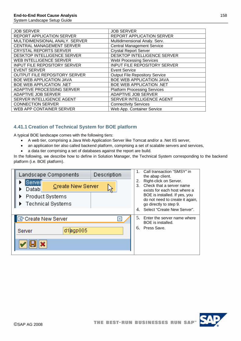
End-to-End Root Cause Analysis 158 System Landscape Setup Guide
©SAP AG 2008
JOB SERVER JOB SERVER REPORT APPLICATION SERVER REPORT APPLICATION SERVER MULTIDIMENSIONAL ANALY. SERVER Multidimensional Analy. Serv. CENTRAL MANAGEMENT SERVER Central Management Service CRYSTAL REPORTS SERVER Crystal Report Server DESKTOP INTELLIGENCE SERVER DESKTOP INTELLIGENCE SERVER WEB INTELLIGENCE SERVER WebI Processing Services INPUT FILE REPOSITORY SERVER INPUT FILE REPOSITORY SERVER EVENT SERVER Event Service OUTPUT FILE REPOSITORY SERVER Output File Repository Service BOE WEB APPLICATION JAVA BOE WEB APPLICATION JAVA BOE WEB APPLICATION .NET BOE WEB APPLICATION .NET ADAPTIVE PROCESSING SERVER Platform Processing Services ADAPTIVE JOB SERVER ADAPTIVE JOB SERVER SERVER INTELLIGENCE AGENT SERVER INTELLIGENCE AGENT CONNECTION SERVER Connectivity Services WEB APP CONTAINER SERVER Web App. Container Service
4.41.1 Creation of Technical System for BOE platform A typical BOE landscape comes with the following tiers:
A web tier, comprising a Java Web Application Server like Tomcat and/or a .Net IIS server, an application tier also called backend platform, comprising a set of scalable servers and services, a data tier comprising a set of databases against the report are build.
In the following, we describe how to define in Solution Manager, the Technical System corresponding to the backend platform (i.e. BOE platform).
1. Call transaction “SMSY” in the abap client.
2. Right-click on Server. 3. Check that a server name
exists for each host where a BOE is installed. If yes, you do not need to create it again, go directly to step 9.
4. Select “Create New Server”.
5. Enter the server name where BOE is installed.
6. Press Save.

End-to-End Root Cause Analysis 159 System Landscape Setup Guide
©SAP AG 2008
7. Maintain at least the fields “Fully-Qualified Host Name” and “IP-Address”.
8. Press “Save”.
9. Right-click on Databases. 10. Select “Create New
Database”.
11. Create a database entry for BOE Central Repository (CMS database). You should use the same SID than BOE Technical System. See recommendation for BOE Technical System SID below.
12. Enter the information requested and especially fields Manufacturer and Server.
Remark: not all databases supported by BOE 3.x can be setup in Solution Manager EhP1. If the database is not in the proposed list (e.g. MySql) you can skip this step; DBA Cockpit application won’t be available to perform remote database monitoring.

End-to-End Root Cause Analysis 160 System Landscape Setup Guide
©SAP AG 2008
13. Right-click on Technical Systems.
14. Select “Create New Technical System”.
15. Enter the System ID of the BOE system as Technical System name.
Please note: - Business Objects
Enterprise does not have a System ID concept, however, in order to identify the system uniquely in Solution Manager, you need to make up and enter a unique system ID here. Usually a Technical System is identified by three letters in upper case (long SID can be longer).
- The following pattern is recommended for the SID: BOE_DEV, BOE_TEST, BOE_QA, BOE_PROD
- If several technical systems of the same type (DEV, TEST, QA…) exist, you can use a number to distinguish them: BOE1_DEV, BOE2_DEV, BOE1_PRD…
16. Select type “Unspecified”. 17. You can leave the field
Installation Number free. 18. Select “Save”.

End-to-End Root Cause Analysis 161 System Landscape Setup Guide
©SAP AG 2008
19. Select tab “Header Data” 20. Select Flag “Production” in
case it is a production system.
21. If you have created a database in the previous steps, select it.
22. Select tab “Instances”. 23. Repeat steps 24, 25 and 26
for each host where BOE platform is installed:
24. Add a new line. 25. Select the Server in field
“Server”. 26. Maintain Instance’s names
according to the following naming convention: BOE_<Server Name> Please Note: in the convention above “BOE” is a constant and as nothing to do with the SID of the Technical System.

End-to-End Root Cause Analysis 162 System Landscape Setup Guide
©SAP AG 2008
27. Select the tab “Software Components”.
28. Select button: “of Prod. Instance”.
29. Select Product “SBOP BI PLATFORM (ENTERPRISE).”
30. Select Product Version “BOBJ Enterprise XI 3.1”.
31. Select Product Instance “REPORT APPLICATION SERVER”.
32. Select “Continue” (Enter). 33. Repeat steps 28, 29, 30, 31,
32 for the following Product Instances (use the same Product and Product Version):
xxvii. DESKTOP INTELLIGENCE SERVER
xxviii. EVENT SERVER xxix. INPUT FILE REPOSITORY
SERVER xxx. JOB SERVER xxxi. MULTIDIMENSIONAL ANALY.
SERVER xxxii. OUTPUT FILE REPOSITORY
SERVER xxxiii. CENTRAL MANAGEMENT
SERVER xxxiv. CONNECTION SERVER xxxv. WEB INTELLIGENCE SERVER xxxvi. ADAPTIVE JOB SERVER xxxvii. ADAPTIVE PROCESSING
SERVER xxxviii. SERVER INTELLIGENCE
AGENT xxxix. WEB APP.CONTAINER
SERVER (only for XI 3.1) 34. Save your changes.
4.41.2 Creation of Technical System for BOE Web Application Server A typical BOE system contains one java Web Application Server or more. Tomcat is the WAS installed by default but more are supported (like SAP J2EE and WebSphere). Whatever the type of WAS installed (even SAP J2EE), you should follow the following procedure based on a Technical System of type “Unspecified”. In the case the WAS is installed on several hosts, only one Technical System should be created with several instances.
1. Call transaction “SMSY”. 2. Right-click on Server. 3. Check that a server name
exists for each host where the

End-to-End Root Cause Analysis 163 System Landscape Setup Guide
©SAP AG 2008
WAS is installed. If yes, you do not need to create it again, go directly to step 9.
4. Select “Create New Server”.
5. Enter the server name where the WAS is installed.
6. Press Save.
7. Maintain at least the fields “Fully-Qualified Host Name” and “IP-Address”.
8. Select “Save”.
9. Right-click on Technical Systems.
10. Select “Create New Technical System”.
27. Enter the System ID of the WAS system as Technical System name.
Please note: - BOE WAS might not have
a System ID concept, however, in order to identify the system uniquely in Solution Manager, you need to make up and enter a unique system ID here.

End-to-End Root Cause Analysis 164 System Landscape Setup Guide
©SAP AG 2008
Usually a Technical System is identified by three letters in upper case (long SID can be longer).
- The following pattern is recommended for the SID: BOW_DEV, BOW_TEST, BOW_QA, BOW_PROD
- If several technical systems of the same type (DEV, TEST, QA…) exist, you can use a number to distinguish them: BOW1_DEV, BOW2_DEV, BOW1_PRD…
11. Select type “Unspecified”. 12. You can leave the field
Installation Number free. 13. Select “Save”.
14. Select tab “Header Data” 15. Select Flag “Production” in
case it is a production system.
16. Select tab “Instances” 17. Repeat the steps 18, 19 and
20 for each host where the WAS is installed:
18. Add a new line. 19. Select the Server in field
“Server”. 20. Maintain the Instance Names
according to the following naming convention: WAS_<Server Name>. Remark, “WAS” is a constant and as nothing to do with Technical System’s SID.

End-to-End Root Cause Analysis 165 System Landscape Setup Guide
©SAP AG 2008
21. Select tab “Software Components”
22. Select button: “of Prod. Instance”
23. Select Product “SBOP ENTERPRISE”
24. Select Product Version “BOBJ Enterprise XI 3.1”
25. Select Product Instance “BOE WEB APPLICATION JAVA”.
26. Select “Continue” (Enter).
27. Save your changes.
4.41.3 Creation of Technical System for BOE IIS server This chapter is relevant only if IIS Server is part of the landscape (Windows only).
1. Call transaction “SMSY”. 2. Right-click on Server. 3. Check if the server name
where IIS is installed is already there. If yes, you do not need to create it again, go directly to step 9.
4. Select “Create New Server”.
5. Enter the server name where your IIS is installed.
6. Press Save.

End-to-End Root Cause Analysis 166 System Landscape Setup Guide
©SAP AG 2008
7. Maintain at least the fields “Fully-Qualified Host Name” and “IP-Address”.
8. Select “Save”.
9. Right-click on Technical Systems.
10. Select “Create New Technical System”.
28. Enter the System ID of the IIS system as Technical System.
Please note: - IIS doesn’t have a
System ID concept, however, in order to identify the system uniquely in Solution Manager, you need to make up and enter a unique system ID here. Usually a Technical System is identified by three letters in upper case (long SID can be longer).
- The following pattern is

End-to-End Root Cause Analysis 167 System Landscape Setup Guide
©SAP AG 2008
recommended for the SID: BON_DEV, BON_TEST, BON_QA, BON_PROD
- If several technical systems of the same type (DEV, TEST, QA…) exist, you can use a number to distinguish them: BON1_DEV, BON2_DEV, BON1_PRD…
11. Select type “MS.Net”. 12. You can leave the field
Installation Number free. 13. Select “Save”.
14. Select tab “Header Data” 15. Select Flag “Production” if it is
a production system
16. Select tab “Instances” 17. Repeat the steps 18, 19 20
for each server (host) where IIS is installed:
18. Add a new line. 19. Select the Server in field
“Server”. 20. Maintain the Instance Name
according to the following naming convention: IIS_<Server Name>
21. Select tab “Software Components”
22. Select button: “of Prod. Instance”
23. Select Product “MS IIS”. 24. Select the correct IIS Version. 25. Select Product Instance “MS
IIS”. 26. Select “Continue (Enter)” Please note: If the system is running on Windows 2003 Servers, the correct MS IIS Version is probably 6.0. In case of
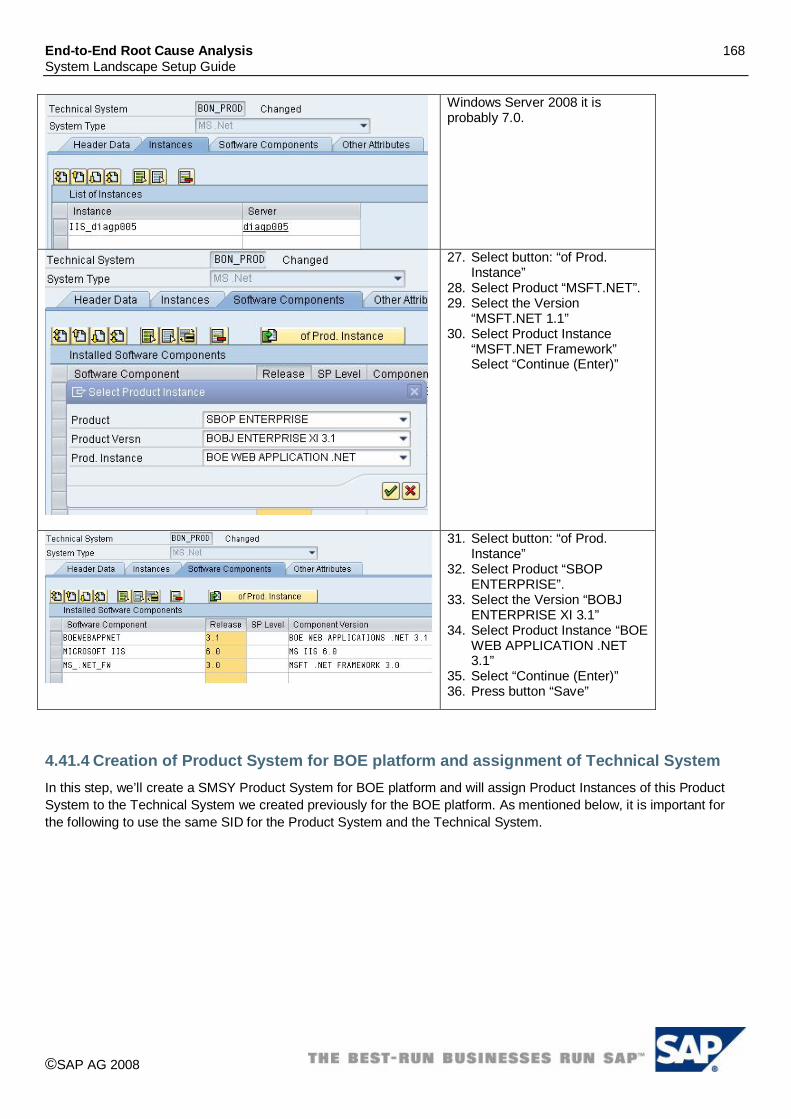
End-to-End Root Cause Analysis 168 System Landscape Setup Guide
©SAP AG 2008
Windows Server 2008 it is probably 7.0.
27. Select button: “of Prod. Instance”
28. Select Product “MSFT.NET”. 29. Select the Version
“MSFT.NET 1.1” 30. Select Product Instance
“MSFT.NET Framework” Select “Continue (Enter)”
31. Select button: “of Prod. Instance”
32. Select Product “SBOP ENTERPRISE”.
33. Select the Version “BOBJ ENTERPRISE XI 3.1”
34. Select Product Instance “BOE WEB APPLICATION .NET 3.1”
35. Select “Continue (Enter)” 36. Press button “Save”
4.41.4 Creation of Product System for BOE platform and assignment of Technical System In this step, we’ll create a SMSY Product System for BOE platform and will assign Product Instances of this Product System to the Technical System we created previously for the BOE platform. As mentioned below, it is important for the following to use the same SID for the Product System and the Technical System.

End-to-End Root Cause Analysis 169 System Landscape Setup Guide
©SAP AG 2008
1. Execute transaction SMSY in Solution Manager.
2. On the left side select “Landscape Components”.
3. Select node “Product Systems”. 4. Create a system for product “SBOP
ENTERPRISE” and product version “BOBJ ENTERPRISE XI 3.1”. (do a right click on product “SBOP ENTERPRISE” and select “Create New System”)
5. Enter the same System ID than the Technical System created for BOE platform.
6. Select tab “Product Instance Selection” 7. On the top menu, select “Display <->
Change” (also button Ctrl + F1). 8. In front of Product Instance “ADAPTIVE
JOB SERVER” check checkbox “Relevant”. 9. In front of Product Instance “ADAPTIVE
JOB SERVER” check checkbox “Technical System”.
10. In front of Product Instance “ADAPTIVE JOB SERVER”, enter Technical System created for BOE platform (it should have the same SID).
11. Select Technical System type “Unspecified”.
12. Repeat the Technical System assignment operation (steps 8 to 11) for the following Product Instances:
xl. CENTRAL MANAGEMENT SERVER xli. CRYSTAL REPORTS SERVER xlii. DESKTOP INTELLIGENCE SERVER xliii. EVENT SERVER xliv. INPUT FILE REPOSITORY SERVER xlv. JOB SERVER xlvi. MULTIDIMENSIONAL ANALY. SERVER xlvii. OUTPUT FILE REPOSITORY SERVER xlviii. REPORT APPLICATION SERVER xlix. CONNECTION SERVER
l. WEB INTELLIGENCE SERVER li. ADAPTIVE JOB SERVER (already done) lii. ADAPTIVE PROCESSING SERVER liii. SERVER INTELLIGENCE AGENT liv. WEB APP.CONTAINER SERVER (only for
version 3.1) 13. Press “Save”. 14. On the top menu, select “Display <->
Change” (also button Ctrl + F1).

End-to-End Root Cause Analysis 170 System Landscape Setup Guide
©SAP AG 2008
4.41.5 Creation of Product System for BOE WAS and assignment of Technical System In this step, we’ll create a SMSY Product System for BOE Web Application Server and will assign Product Instances of this Product System to the Technical System we created previously for the WAS. As mentioned below, it is important for the following to use the same SID for the Product System and the Technical System.
1. Execute transaction SMSY in Solution Manager.
2. On the left side select “Landscape Components”.
3. Select node “Product Systems”.
4. Create a system for product “SBOP ENTERPRISE” and product version “BOBJ ENTERPRISE XI 3.1”. (do a right click on product “SBOP ENTERPRISE” and select “Create New System”)
5. Enter the same System ID than the Technical System created for BOE WAS.
6. Select tab “Product Instance Selection”
7. On the top menu, select “Display <-> Change” (also button Ctrl + F1).
8. In front of Product Instance “BOE WEB APPLICATION JAVA” check checkbox “Relevant”.
9. In front of Product Instance “BOE WEB APPLICATION JAVA” check checkbox “Technical System”.
10. In front of Product Instance “BOE WEB APPLICATION JAVA”, enter Technical System created for BOE WAS (it should have the same SID).
11. Select Technical System type “Unspecified”.
12. Press “Save”. 13. On the top menu, select
“Display <-> Change” (also button Ctrl + F1).

End-to-End Root Cause Analysis 171 System Landscape Setup Guide
©SAP AG 2008
4.41.6 Creation of Product System for BOE IIS and assignment of Technical System This is an optional step, relevant only if the BOE landscape contains an IIS server. In the following, we’ll create a SMSY Product System for BOE IIS and will assign Product Instances of this Product System to the corresponding Technical System we created previously. As mentioned below, it is important for the following to use the same SID for the Product System and the Technical System.
1. Execute transaction SMSY in Solution Manager.
2. On the left side select “Landscape Components”.
3. Select node “Product Systems”.
4. Create a system for product “MS IIS” and product version “MS IIS 6.0” (or the version of IIS relevant to your landscape). (do a right click on product “MS IIS” and select “Create New System”)
5. Enter the same System ID than the Technical System created for BOE IIS (type MS .Net).
6. Press button “Installed Product Versions”.
7. Check checkbox “Free Product/Select Product Version”.
8. Add product “MSFT .NET” and product version corresponding to your system.
9. Add product “SBOP ENTERPRISE” and product version “BOBJ ENTERPRISE XI 3.1”.
10. Press “Copy”.

End-to-End Root Cause Analysis 172 System Landscape Setup Guide
©SAP AG 2008
11. Answer “No” to the popup “Copy product instance assignments?”.
12. Press “Save”.
13. Select tab “Product Instance Selection”
14. On the top menu, select “Display <-> Change” (also button Ctrl + F1).
15. In front of Product Instance “MS IIS” check checkbox “Relevant”.
16. In front of Product Instance “MS IIS” check checkbox “Technical System”.
17. In front of Product Instance “MS IIS”, enter Technical System created for BOE IIS.
18. Select Technical System type “MS .Net”.
19. Press “Save”. 20. On the top menu, select
“Display <-> Change” (also button Ctrl + F1).
21. On the left side, under Product Systems node, select product “MSFT .Net”.
22. Product system created above for product “MS IIS” should be listed (with the same system ID).
23. Select tab “Product Instance Selection”
24. On the top menu, select “Display <-> Change” (also button Ctrl + F1).
25. In front of Product Instance “MS .Net Frame” check checkbox “Relevant”.
26. In front of Product Instance “MS .Net Frame” check checkbox “Technical

End-to-End Root Cause Analysis 173 System Landscape Setup Guide
©SAP AG 2008
System”. 27. In front of Product Instance
“MS .Net Frame”, enter Technical System created for BOE IIS.
28. Select Technical System type “MS .Net”.
29. Press “Save”. 30. On the top menu, select
“Display <-> Change” (also button Ctrl + F1).
31. Press “Save”.
32. On the left side, under Product Systems node, select product “SBOP ENTERPRISE”.
33. Product system created above for product “MS IIS” should be listed (with the same system ID).
34. Select tab “Product Instance Selection”
35. On the top menu, select “Display <-> Change” (also button Ctrl + F1).
36. In front of Product Instance “BOE WEB APPLICATION .NET” check checkbox “Relevant”.
37. In front of Product Instance “BOE WEB APPLICATION .NET” check checkbox “Technical System”.
38. In front of Product Instance “BOE WEB APPLICATION .NET”, enter Technical System created for BOE IIS.
39. Select Technical System type “MS .Net”.
40. Press “Save”. 41. On the top menu, select
“Display <-> Change” (also button Ctrl + F1).
42. Press “Save”.

End-to-End Root Cause Analysis 174 System Landscape Setup Guide
©SAP AG 2008
4.41.7 Managed System Setup of BOE platform Technical System The following describes the managed system setup procedure for BOE platform Technical System.
1. Open the configuration wizard for SAP Solution Manager (Transaction: SOLMAN_SETUP).
2. Select Managed System Configuration. 3. Select or enter system type UNSPECIFIC. 4. Select BOE platform Technical System in the
list. 5. Press “Configure System”.
6. For each activity, a detailed description is available in the linked IMG documentation.
7. Perform activity “Diagnostics Prerequisites” 8. When the activity is done. Press the button
“Change”, set the execution status to “performed” and press “Save”.
9. Press “Continue” 10. Perform activity “Install Diagnostics Agent” if
not already done. SAP Host Control and Diagnostics Agent needs to be installed on all hosts where BOE platform is installed. Please refer to: SAP Note 1234387.
11. When the activity is done. Press the button “Change”, set the execution status to “performed” and press “Save”.
12. Perform activity ”Maintain SAP Router data”. Remark: you can come back later to an activity if you don’t have the information at hand.
13. When the activity is done. Press the button “Change”, set the execution status to “performed” and press “Save”.
14. If relevant, perform the activity “Configure DBA Cockpit” for Central Repository (CMS DB).
15. When the activity is done. Press the button “Change”, set the execution status to “performed” and press “Save”.
16. Press “Continue”.

End-to-End Root Cause Analysis 175 System Landscape Setup Guide
©SAP AG 2008
17. You are on the step 3, “Diagnostics
Configuration”. 18. Start the diagnostics wizard using the button
“Open URL”. You must configure Diagnostics for the BOE platform Technical System. See following steps.
19. Your system is pre-selected.
20. Open the tray “Managed Products”
21. Mark the system as relevant for diagnostics (i.e. uncheck the check box).
22. Press “Set”.

End-to-End Root Cause Analysis 176 System Landscape Setup Guide
©SAP AG 2008
23. Open the tray “Product Instances”.
24. Select following Product Instances relevant for diagnostics:
lv. CENTRAL MANAGEMENT SERVER
lvi. CRYSTAL REPORTS SERVER lvii. DESKTOP INTELLIGENCE
SERVER lviii. EVENT SERVER lix. INPUT FILE REPOSITORY
SERVER lx. JOB SERVER lxi. MULTIDIMENSIONAL ANALY.
SERVER lxii. OUTPUT FILE REPOSITORY
SERVER lxiii. REPORT APPLICATION
SERVER lxiv. CONNECTION SERVER lxv. WEB INTELLIGENCE SERVER lxvi. ADAPTIVE JOB SERVER lxvii. ADAPTIVE PROCESSING
SERVER lxviii. SERVER INTELLIGENCE
AGENT lxix. WEB APP.CONTAINER
SERVER (only for version 3.1) 25. Press “Set”. 26. Press “Setup …” in the
bottom of the page.
27. For each server instance, repeat steps below: 28, 29, 30, 31 and 32.
28. Expand the details tray (small black arrow in the upper left of the table).
29. Check that the SMD Agent is selected properly (agent must be up and running).
30. Select the relevant Wily Introscope Manager.
31. Enter the installation path of the system. Example:
“C:\Program Files\Business Objects\BusinessObjects Enterprise 12.0\”. As a landmark, just under the

End-to-End Root Cause Analysis 177 System Landscape Setup Guide
©SAP AG 2008
installation directory, you should find the directory “logging” on Windows and the directory “bobje” on Unix like systems.
32. Press “Set”.
26. Enter the host and the port of the load balancer. If there is no load balancer, enter directly the host and the port of the BOE Web Application Server (one of them if there are several).
27. Press “Save”.
28. Select all the instances to setup. There should be one instance per instance defined in SMSY Technical System (i.e. one instance pert host where BOE platform is installed).
29. Press “Next”.
30. Press “Setup”. 31. Wait the end of the setup
tasks (the screen is refreshed automatically). It can take several minutes.
32. Check that all setup tasks finished successfully (green status).
33. Press “Quit”.
4.41.8 Managed System Setup of BOE WAS Technical System The following describes the managed system setup procedure for BOE Web Application Server (WAS) Technical System(s). If there are several Web Application Servers configured, then you need to perform the managed system setup for all of them.

End-to-End Root Cause Analysis 178 System Landscape Setup Guide
©SAP AG 2008
1. Open the configuration wizard for SAP Solution Manager (Transaction: SOLMAN_SETUP).
2. Select Managed System Configuration. 3. Select or enter system type UNSPECIFIC. 4. Select BOE WAS Technical System in the
list. 5. Press “Configure System”.
6. For each activity, a detailed description is available in the linked IMG documentation.
7. Perform activity “Diagnostics Prerequisites”. 8. When the activity is done. Press the button
“Change”, set the execution status to “performed” and press “Save”.
9. Press “Continue”. 10. Perform activity “Install Diagnostics Agent” if
not already done. SAP Host Control and Diagnostics Agent needs to be installed on all hosts where BOE WAS is installed. Please refer to: SAP Note 1234387.
11. When the activity is done. Press the button “Change”, set the execution status to “performed” and press “Save”.
12. Perform activity ”Maintain SAP Router data”. Remark: you can come back later to an activity if you don’t have the information at hand.
13. When the activity is done. Press the button “Change”, set the execution status to “performed” and press “Save”.
14. Press “Continue”.
15. You are on the step 3, “Diagnostics
Configuration”. 16. Start the diagnostics wizard using the button
“Open URL”. You must configure Diagnostics for the BOE WAS Technical System. See following steps.

End-to-End Root Cause Analysis 179 System Landscape Setup Guide
©SAP AG 2008
17. Technical System is pre-selected.
18. Open the tray “Managed Products”
19. Mark the Technical System as relevant for diagnostics (i.e. uncheck the check box).
20. Press “Set”.
21. Open the tray “Product Instances”.
22. Select the following Product Instances relevant for diagnostics:
lxx. BOE WEB APPLICATION JAVA 23. Press “Set”. 24. Press “Setup …” in the
bottom of the page.
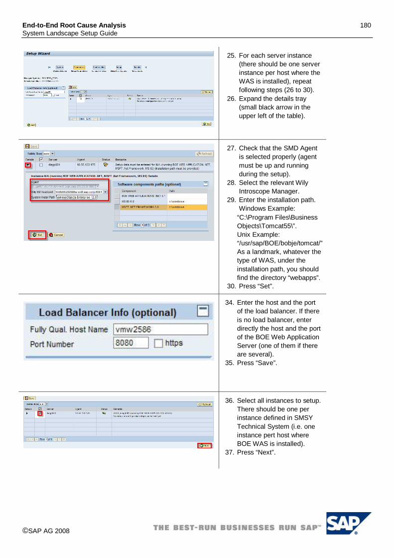
End-to-End Root Cause Analysis 180 System Landscape Setup Guide
©SAP AG 2008
25. For each server instance (there should be one server instance per host where the WAS is installed), repeat following steps (26 to 30).
26. Expand the details tray (small black arrow in the upper left of the table).
27. Check that the SMD Agent is selected properly (agent must be up and running during the setup).
28. Select the relevant Wily Introscope Manager.
29. Enter the installation path. Windows Example:
“C:\Program Files\Business Objects\Tomcat55\”. Unix Example: “/usr/sap/BOE/bobje/tomcat/” As a landmark, whatever the type of WAS, under the installation path, you should find the directory “webapps”.
30. Press “Set”.
34. Enter the host and the port of the load balancer. If there is no load balancer, enter directly the host and the port of the BOE Web Application Server (one of them if there are several).
35. Press “Save”.
36. Select all instances to setup. There should be one per instance defined in SMSY Technical System (i.e. one instance pert host where BOE WAS is installed).
37. Press “Next”.

End-to-End Root Cause Analysis 181 System Landscape Setup Guide
©SAP AG 2008
38. Press “Setup”. 39. Wait the end of the setup
tasks (page is refreshed automatically).
40. Check that all setup tasks finished successfully (green status).
41. Press “Quit”.
4.41.9 Managed System Setup of BOE IIS Technical System The following describes the managed system setup procedure for MS IIS Technical System (optional).
1. Open the configuration wizard for SAP Solution Manager (Transaction: SOLMAN_SETUP).
2. Select Managed System Configuration. 3. Select or enter system type “MS .Net”. 4. Select BOE IIS Technical System in the list. 5. Press “Configure System”.

End-to-End Root Cause Analysis 182 System Landscape Setup Guide
©SAP AG 2008
6. For each activity, a detailed description is available in the linked IMG documentation.
7. Perform activity “Diagnostics Prerequisites” 8. When the activity is done. Press the button
“Change”, set the execution status to “performed” and press “Save”.
9. Press “Continue” 10. Perform activity “Install Diagnostics Agent” if
not already done. SAP Host Control and Diagnostics Agent needs to be installed on all hosts where IIS server is installed. Please refer to: SAP Note 1234387.
11. When the activity is done. Press the button “Change”, set the execution status to “performed” and press “Save”.
12. Perform activity ”Maintain SAP Router data”. Remark: you can come back later to an activity if you don’t have the information at hand.
13. When the activity is done. Press the button “Change”, set the execution status to “performed” and press “Save”.
14. Press “Continue”.
15. You are on the step 3, “Diagnostics
Configuration”. 16. Start the diagnostics wizard using the button
“Open URL”. You must configure Diagnostics for the BOE IIS Technical System. See following steps.

End-to-End Root Cause Analysis 183 System Landscape Setup Guide
©SAP AG 2008
17. Your system is pre-selected.
18. Open the tray “Managed Products”
19. Mark the Technical System as relevant for diagnostics (i.e. uncheck the check box).
20. You should see a list of several products (normally 3), select:
BOBJ ENTERPRISE XI 3.1 MS IIS 6.0 (or relevant
version for your Technical System)
MSFT .NET 3.0 (or relevant version for your Technical System) 21. Press “Set”.
22. Open the tray “Product Instances”.
23. Select the following Product Instances relevant for diagnostics:
lxxi. BOE WEB APPLICATION .NET
lxxii. MS IIS lxxiii. MSFT .Net Framework
24. Press “Set”. 25. Press “Setup …” in the
bottom of the page.

End-to-End Root Cause Analysis 184 System Landscape Setup Guide
©SAP AG 2008
26. For each server instance (there should be one per host where IIS is installed), repeat the following steps (27 to 32).
27. Expand the details tray (small black arrow in the upper left of the table).
28. Check that the SMD Agent is selected properly (agent must be up and running during the setup).
29. Select the relevant Wily Introscope Manager.
30. Enter the same installation path than for BOE Technical System. Example: “C:\Program Files\Business Objects\BusinessObjects Enterprise 12.0\”.
31. Expand the tray “Software Components paths (optional)” and enter the Windows directory in front of components “MS IIS” and “MSFT .Net”.Expand the tray Software components paths.
32. Press “Set”.
33. Enter the host and the port of the load balancer. If there is no load balancer, enter directly the host and the port of the BOE IIS server.
34. Press “Save”.

End-to-End Root Cause Analysis 185 System Landscape Setup Guide
©SAP AG 2008
35. Select all instances to setup. There should be one instance per instance defined in SMSY Technical System (i.e. one instance pert host where BOE IIS server is installed).
36. Press “Next”.
37. Press “Setup”. 38. Wait the end of the setup
tasks (screen is automatically refreshed).
39. Check that all setup tasks finished successfully (green status).
40. Press “Quit”.
4.41.10 Setup configuration extraction of BOE platform Technical System In the following steps we configure the extraction of configuration stored in the Central Repository. Remark: For Unix managed systems, you need a Solution Manager EhP1 SP21 or upper to use the configuration extraction script. Install the extraction component on BOE system If BOE’s version is 3.1 SP2 or upper, you do not need to install the extraction component on the managed system, you can go directly to next step (“Create a read only administrator user on BOE system”). For previous versions (3.0 or 3.1), it is necessary to download and install the component called BOE configuration extraction script. BOE configuration extraction script needs to be installed on all hosts of the managed system. In addition to this, some configuration steps are necessary. The location from where you can download the configuration extraction script and the additional steps are described in SAP note 1357901. Create a read only administrator user on BOE system For security reason, the configuration extraction should not be configured with a user having write access to BOE system. A dedicated read only user should be used instead. The procedure below explains how to create such a read-only user with sufficient authorization to execute the configuration extraction script. Remark: Instead of directly assign the authorizations to a user, as described here under, it is also possible to assign the authorizations to a dedicated group that will be assign later on to the user.

End-to-End Root Cause Analysis 186 System Landscape Setup Guide
©SAP AG 2008
1. Log in the CMC using your usual Administrator Login.
http://< WAS host>:<WAS
port>/CmcApp/logon.faces Where WAS is the Web
Application Server (e.g. Tomcat)
2. Create a new user. First go in “Users and Groups”.
3. Click on the icon « Create new user ».

End-to-End Root Cause Analysis 187 System Landscape Setup Guide
©SAP AG 2008
4. Give a name to the user, fill in the password and click « create and close ».
5. Go in « Applications », select CMC and right click and choose « User security ».
6. Click on « Add principals ».
7. Select your created user on the left and add it to the right column, then click “add and assign security”.
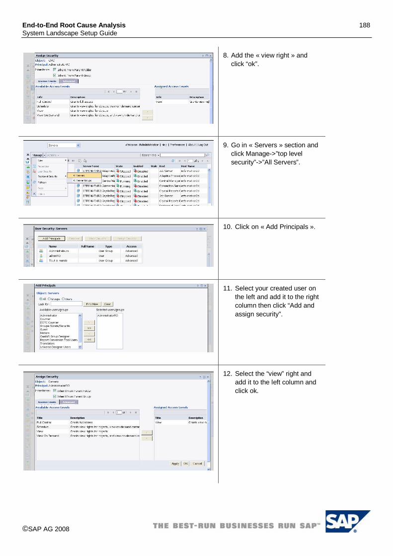
End-to-End Root Cause Analysis 188 System Landscape Setup Guide
©SAP AG 2008
8. Add the « view right » and click “ok”.
9. Go in « Servers » section and click Manage->”top level security”->”All Servers”.
10. Click on « Add Principals ».
11. Select your created user on the left and add it to the right column then click “Add and assign security”.
12. Select the “view” right and add it to the left column and click ok.

End-to-End Root Cause Analysis 189 System Landscape Setup Guide
©SAP AG 2008
13. In the Servers Section, select Manage-> Top-Level security -> All Servers Groups, and repeat steps 10, 11 and 12.
14. In the Folders Section, select Manage-> Top-Level security -> All Folders, and repeat steps 10, 11 and 12.
15. In the “Personals Folders” Section, select Manage-> Top-Level security -> All Personal Folders, and repeat steps from step 10.
16. In the “Inboxes” Section, select Manage-> Top-Level security -> All Inboxes, and repeat steps from step 10.
17. Login as your new user to validate that you can logon and see: servers list, folders, personal folders and inboxes.
Enter the configuration extraction properties
1. Logon to “Agent Administration” web UI. With an administrator user, the link is accessible in the left pane of RCA Work Center.
2. Select tab “Applications Configuration”.
3. On the left pane select agent application “com.sap.smd.agent.application.remoteos”.
4. Select the scope corresponding to the host where BOE platform is installed. If BOE platform is installed on several hosts, this procedure must be repeated for each of them (i.e. on all hosts where at least one BOE platform server is running). Remark: the agent must be connected to be visible in the dropdown “Scope”.
5. Press “Edit”. 6. Press “Add Property”.

End-to-End Root Cause Analysis 190 System Landscape Setup Guide
©SAP AG 2008
7. Add the following properties:
PROPERTY NAME Description ENV_SID_<SID>_BOE_DIR BOE installation directory. Caution: this is not the same directory
entered during the Diagnostics setup but one level above. As a landmark, On a Windows OS, under the installation directory, you should find directories “tomcat55” & “common”. On a Unix OS, under the installation directory, you can find directories “tomcat” & “java”. Windows example: C:\Program Files\Business Objects\ Unix example: /usr/BOE/bobje/
ENV_SID_<SID>_BOE_CMS CMS connection string: <CMS host>:<CMS port>. In the case several CMS are available, whatever CMS should be ok. Remark: load balancing does not work for configuration extraction (i.e. configuration won’t be collected for the host if the selected CMS is down). Example: NCED60185602A:6400
ENV_SID_<SID>_BOE_CMS_USR CMS user with read only access to the Central Repository. See chapter “Create read only CMS user”. You should check the checkbox “Secure Property” so that the user’s name won’t be displayed later on in the UI.
ENV_SID_<SID>_BOE_CMS_PWD Password for the CMS user. You should check the checkbox “Secure Property” so that the user’s password won’t be displayed later on in the UI.
(*) Where <SID> is the long SID of the BOE Technical System entered in SMSY (e.g. BOE_PROD)
8. Don’t forget to press “Save” button when you have finished.
Check that configuration extraction is working properly

End-to-End Root Cause Analysis 191 System Landscape Setup Guide
©SAP AG 2008
1. Log in the RCA Work Center. 2. Select “Host Analysis”. 3. Select one of the hosts where
BOE is installed. 4. OS Command Console
application is opened in an external window.
5. Select the relevant Technical System ID.
6. Select the group “BOE”. 7. Select the command
“DumpServerAps”. 8. Press button “Send
Command”. 9. The configuration of the CMS
server running on the selected host should be displayed in the result window (If a CMS is running on the host).
Remarks:
If BOE servers are installed on several hosts, you should check the configuration extraction on all of them.
You can also select other commands depending on what type of server are installed on the host.
In the test fail, you should check the application logs of the corresponding SMD Agent. As the agent’s user executes some commands located under BOE’s installation folders, it is necessary that he has enough authorizations to do so (read & execution).
4.41.11 Configuration of Remote Database Monitoring DBA Cockpit can be configured for CMS DB (Central Repository) using the wizard. For all other databases (customer databases) connected to BOE, please refer to SAP Note 1265134: “DBA Cockpit: Connecting a remote database”.

End-to-End Root Cause Analysis 192 System Landscape Setup Guide
©SAP AG 2008
4.42 SAP Business Objects Explorer XI 3.2 For SBOP Explorer XI 3.2 an automated creation of the technical landscape via SLD is not available. Therefore you have to maintain the technical landscape manually in transaction ‘SMSY’ and afterwards perform the Diagnostics Configuration for the BOE system using the “Diagnostics Setup” wizard. In the following we assume that Solution Manager is properly configured and the SMD agents have been installed and connected to the server. As first step you have to perform the setup for the basis platform “SAP Business Objects Enterprise XI 3.1” as described in the appropriate chapter in this document. The Business Objects Explorer will run as components on this system and will therefore use the same SID and technical systems as the “BO Enterprise XI” system. In our Example we use ‘B32’ as the SID of the BOE server stack and ‘B32_WAS’ as the SID of the BOE Web Application Server stack.
4.42.1 Modification of technical system for SBOP Web Application Server If the landscape contains several WAS, only one technical system must be created with several instances.
1. Open the SAP GUI, execute transaction “SMSY” and open ‘Product Systems’
2. Open the product ‘SBOP ENTERPRISE’ and select your SID of the Web Application Server stack of the BOE system (we use ‘B32_WAS’).

End-to-End Root Cause Analysis 193 System Landscape Setup Guide
©SAP AG 2008
3. Select tab ‘Header Data’ and press “Change Product Assignmt”.
4. Select ‘Free Product/Select Product Version’ and then choose the Product “SBOP EXPLORER” and the Product Version “SBOP Explorer XI 3.2” and press “Copy”.
5. Set all products to ‘Active’ and push ‘Save’. Note: In our Example we use TOMCAT 5.5 as WEB Application Server for the BO Enterprise XI, you might have different product versions here.
6. After saving you can go to product ‘SBOP EXPLORER’ and you will now find there a new system entry for you SID, in our example ‘B32_WAS’.

End-to-End Root Cause Analysis 194 System Landscape Setup Guide
©SAP AG 2008
7. There select tab ‘Product Instance Selection’. Mark the product instance ‘Web Gateway’ as ‘Relevant’ and assign the technical system of the web application server to this product instance. Push ‘Save’ Note: In our case the technical System, used already for BOE Web AS, is named ‘B32_WAS’ of type ‘Unspecified’.
8. Now select the product instance ‘Web Gateway’
9. Select tab ‘Software Components’ and push ‘Copy Software components’ (Import of Prod Instance’).
10. Select Product ‘SBOP EXPLORER’, Product Version ‘SBOP EXPLORER XI 3.2’ and Product Instance ‘Web Gateway’. Then push ‘Enter’ to take over the software component and ‘Save’.
11. You should now have 3 Software components: One for the “Web Application Server”, one for “BO Enterprise Web Application” and one for the “BO Explorer Web Application”.

End-to-End Root Cause Analysis 195 System Landscape Setup Guide
©SAP AG 2008
4.42.2 Modification of technical system for SBOP Explorer
1. Open the SAP GUI, execute transaction “SMSY” and open ‘Product Systems’
2. Open the product ‘SBOP ENTERPRISE’ and select your SID of the Server stack of the BOE system (we use ‘B32’).
3. Select tab ‘Header Data’ and press “Change Product Assignmt”.

End-to-End Root Cause Analysis 196 System Landscape Setup Guide
©SAP AG 2008
4. Select ‘Free Product/Select Product Version’ and then choose the Product “SBOP EXPLORER” and the Product Version “SBOP Explorer XI 3.2” and press “Copy”.
5. Set all products to ‘Active’ and push ‘Save’.
6. After saving you can go to product ‘SBOP EXPLORER’ and you will now find there a new system entry for your SID, in our Example ‘B32’.
7. There select tab ‘Product Instance Selection’. Mark the product instances: ‘Exploration Server’, ‘Index Server’, ‘Master Server’ and ‘Search Server’ as ‘relevant’ and assign the technical system to this product instances. Push ‘Save’ Note: In our case the technical System, used already for BOE, is named ‘B32’ of type ‘Unspecified’.
8. Now select the product instance ‘Exploration Server’

End-to-End Root Cause Analysis 197 System Landscape Setup Guide
©SAP AG 2008
9. Select tab ‘Software Components’ and push ‘Copy Software components’ (Import of Prod Instance’).
10. Select Product ‘SBOP EXPLORER’, Product Version ‘SBOP EXPLORER XI 3.2’ and Product Instance ‘Exploration Server’. Then push ‘Enter’ to take over the software component and ‘Save’. Repeat this step to take over also the software components for: ‘Index Server’, ‘Master Server’ and ‘Search Server’
11. You should now have 4 new Software components for the Explorer (additionally to many Software components for the BO Enterprise XI). Note: The SBOP Explorer product was formerly named ‘Polestar’, so you can identify the Explorer software components by ‘Polestar’ at the beginning of the name.
4.42.3 Installation of Diagnostics Agent on all hosts If not already done so, SAP Host Control and a Diagnostics Agent needs to be installed on all hosts where any component of SBOP Explorer is installed (including the hosts where the customer database are installed). Please refer to: SAP Note 1234387.
4.42.4 Diagnostics Configuration for SBOP Explorer technical system After setting up the technical system, the diagnostics configuration needs to be performed.

End-to-End Root Cause Analysis 198 System Landscape Setup Guide
©SAP AG 2008
1. Open the configuration wizard for SAP Solution Manager (Transaction: SOLMAN_SETUP).
2. Select Managed System Configuration. 3. Select or enter system type
UNSPECIFIC. 4. Select the previously used “SBOP
Explorer XI 3.2” technical system (Example: B32).
5. Press “Configure System”.
6. Perform the described steps for the managed system (detailed description available in the linked IMG documentation). The following steps are already processed for the BOE setup:
-“Diagnostics Prerequisites” -“Install Diagnostics Agent -”Maintain SAP Router data” -“Configure DBA Cockpit” for Central Repository (CMS DB). To configure DBA Cockpit for customer databases, see additional steps below. So please go directly to: -“Configure Diagnostics” (see below)
7. Set the status of the activity to “performed” when done.
8. Start the diagnostics wizard using the link Configure Diagnostics (Open URL).

End-to-End Root Cause Analysis 199 System Landscape Setup Guide
©SAP AG 2008
9. Your system is pre-selected. 10. Additionally to product ‘BOBJ Enterprise
XI 3.1’, select “SBOP Explorer XI 3.2”. 11. Push ‘Set’
12. Add the following Main Instances relevant for diagnostics (push ‘CTRL’ key on keyboard and click with the mouse): -Exploration Server -Index Server -Master Server -Search Server
13. Press “Set”. 14. Press “Setup <B32>” at the bottom of
the page.
15. For each server instance… 16. Expand the details tray. 17. Check that the SMD Agent is selected
properly. 18. Check the relevant Wily Introscope
Manager. 19. If not available enter the installation path
of the BOE system. Example: “C:\Program Files (x86)\Business Objects\”.
20. Press “Set”.
21. If there is no load balancer, enter the host and the port of a Web Application Server.
22. Press “Save”.

End-to-End Root Cause Analysis 200 System Landscape Setup Guide
©SAP AG 2008
23. Select all the instances to setup. 24. Press “Next”.
25. Press “Setup”. 26. Wait the end of the setup tasks.
4.42.5 Diagnostics Configuration for SBOP Web Application Server After setting up the technical system, the diagnostics configuration needs to be performed.
1. Open the configuration wizard for SAP Solution Manager (Transaction: SOLMAN_SETUP).
2. Select Managed System Configuration. 3. Select or enter system type
UNSPECIFIC. 4. Select the previously created “SBOP Web
Application Server” technical systems (Example: B32_WAS). Note: There are only the first 3 characters shown of the SID, please use the tooltip of the mouse to find the right System.
5. Press “Configure System”.

End-to-End Root Cause Analysis 201 System Landscape Setup Guide
©SAP AG 2008
6. Perform the described steps for the managed system (detailed description available in the linked IMG documentation). The following steps are already performed:
-“Diagnostics Prerequisites” -“Install Diagnostics Agent -”Maintain SAP Router data” -“Configure DBA Cockpit” for Central Repository (CMS DB). To configure DBA Cockpit for customer databases, see additional steps below. Therefore please go directly to: -“Configure Diagnostics” (see below)
7. Set the status of the activity to “performed” when done.
8. Start the diagnostics wizard using the link Configure Diagnostics (Open URL).
9. Your system is pre-selected. 10. Open the tray and mark the system as
relevant for diagnostics (i.e. uncheck the check box).
11. Add product “SBOP Explorer XI 3.2” (by pushing the ‘Cntrl’ (‘Strg’) - button when you click).
12. Push ‘Set’

End-to-End Root Cause Analysis 202 System Landscape Setup Guide
©SAP AG 2008
13. Add the following Main Instances relevant for diagnostics: -WeB Gateway (by pushing the ‘Cntrl’ (‘Strg’) - button when you click).
14. Press “Set”. 15. Press “Setup” in the bottom of the page.
16. For each server instance… 17. Expand the details tray. 18. Check that the SMD Agent is selected
properly. 19. Select the relevant Wily Introscope
Manager. 20. Enter the installation path of the system.
Example: “C:/Program Files (x86)/Business
Objects/Tomcat55/”. 21. Press “Set”.
22. If there is no load balancer, enter the host and the port of a Web Application Server.
23. Press “Save”.
24. Select all the instances to setup. 25. Press “Next”.

End-to-End Root Cause Analysis 203 System Landscape Setup Guide
©SAP AG 2008
26. Press “Setup”. 27. Wait the end of the setup tasks.
4.42.6 Diagnostics Configuration for SAP BW Accelerator (BWA) To configure SAP BW Accelerator for diagnostics, please follow the instructions in chapter “SAP BW Accelerator (BIA / BWA)”.
4.42.7 Setup database configuration extraction of Business Objects Enterprise To configure the extraction of configuration stored in the Central Repository, please check the description in chapter “Setup database configuration extraction” for Business Objects Enterprise XI 3.1
4.42.8 Configuration of Remote Database Monitoring for Business Objects Enterprise To configure the databases of Business Objects Enterprise for remote DB monitoring, please refer to chapter “Configuration of Remote Database Monitoring” for Business Objects Enterprise XI 3.1.
4.42.9 Additional setup steps Please refer to SAP Note 1388247 for additional steps: “RCA: Managed System Setup for SAP Business Objects Explorer
4.43 SAP eSourcing 4.2, 5.0 For SAP eSourcing an automated creation of the technical system via the SLD is currently not supported. Therefore you have to create the technical system manually and afterwards run connect the managed system using the managed system wizard.
4.43.1 Manual creation of technical system for SAP eSourcing

End-to-End Root Cause Analysis 204 System Landscape Setup Guide
©SAP AG 2008
16. Open the “system maintenance” application from the common tasks area of the Root Cause Analysis Workcenter (Transaction: SOLMAN_WORKCENTER)
17. Select Create
18. Enter a System ID for your eSourcing Server into field “Technical System”, select type “unspecified” and enter a description.
19. Select Save
20. Select “Add Main Instance”.
21. Select the Product Version “SAP E-Sourcing/CLM SAP E-Sourcing 5.0” or SAP

End-to-End Root Cause Analysis 205 System Landscape Setup Guide
©SAP AG 2008
E-Sourcing 4.2 Main Instance “E-Sourcing SRM Java Server, E-Sourcing Optimizer, E-Sourcing Generator”
22. Select Save 23. Flag the System as
“Production”. 24. Select Save
25. Select Tab “Instances”. 26. Enter the E-Sourcing
Instances, the Server and the corresponding Server Roles. For the instance naming convention we recommend the following: <server>_<SID>_<#>
27. If you cannot select the appropriate server from the value help, create a new server using the button.

End-to-End Root Cause Analysis 206 System Landscape Setup Guide
©SAP AG 2008
28. Select Tab “Database”. 29. You are not able to
create Database server here. You have to use transaction code “smsy” in ABAP stack to create Database and select E-Sourcing server. After Database is created. You should be able to see Database information after you select “Database”
4.43.2 Diagnostics Configuration After making sure that your SAP E-Sourcing system is correctly set up, you can proceed with the diagnostics configuration for you SAP E-Sourcing system.
10. Open the diagnostics setup application from the common tasks area of the Root Cause Analysis Workcenter (Transaction: SOLMAN_WORKCENTER)
11. Choose “Managed Systems”
12. Choose “Setup Wizard”

End-to-End Root Cause Analysis 207 System Landscape Setup Guide
©SAP AG 2008
13. Jump to the SID of your E-Sourcing

End-to-End Root Cause Analysis 208 System Landscape Setup Guide
©SAP AG 2008
14. Set the E-Sourcing as ‘Diagnostics Relevant’
15. Start the Setup using the “Setup SID (PRODUCT)” button
16. In the Setup Parameters step, ensure the following settings
a. Select your wily server
b. Please fill in n the System Install Path:
i. D:/jboss/jbossb/jboss-3.2.7/ if your installation path is selected as this otherwise enter your system installation path
ii. Add Component path
17. After this is done, continue with the setup.

End-to-End Root Cause Analysis 209 System Landscape Setup Guide
©SAP AG 2008
18. select wily server
19. after successfully setup you should green traffic light
4.44 SAP POS 2.0, 2.1, 2.2 and 2.3
For SAP POS an automated creation of the technical system via the SLD is currently not supported. Therefore you have to create the technical system manually and afterwards run connect the managed system using the managed system wizard.
4.44.1 Manual creation of technical system for SAP POS

End-to-End Root Cause Analysis 210 System Landscape Setup Guide
©SAP AG 2008
1. Open the system maintenance application from the common tasks area of the Root Cause Analysis Workcenter (Transaction: SOLMAN_WORKCENTER)
2. Select Create

End-to-End Root Cause Analysis 211 System Landscape Setup Guide
©SAP AG 2008
3. Enter a System ID for your SAP POS system into the field “Technical System”, select type “Unspecified” and enter a description.
4. Select Save
5. Select “Add Main Instance”. 6. Select the Product Version, e.g. “SAP POS 2.1”
Main Instance “Store Server” (you might choose different Main Instances as you need)
7. Flag the System as “Production”. 8. Select Save

End-to-End Root Cause Analysis 212 System Landscape Setup Guide
©SAP AG 2008
9. Select Tab “Instances”. 10. Enter the POS System Instances, the Server and
the corresponding Operating System and its version. For the instance naming convention we recommend the following: <server>_<SID>_<#>
11. If you cannot select the appropriate server from the value help, create a new server using the button.
12. Select Tab “Database”. 13. Enter the POS Server Database via the value
help or create a new database and select “Save”.
4.44.2 Diagnostics Configuration After setting up the technical system, the diagnostics configuration needs to be performed.
1. Log on to your Solution Manager System, Use transaction /nSolMan_WorkCenter.
2. Click the link “Diagnostics Setup” as marked in Red.

End-to-End Root Cause Analysis 213 System Landscape Setup Guide
©SAP AG 2008
3. Choose Managed System.
4. Choose “Setup Wizard” 5. Find out your system ID (SID)
6. Make sure the “Not Diagnostics Relevant” was not selected.
7. Choose Managed System. Choose your Wily EM host from the dropdown list.
8. Enter the System Install Path, e.g. “C:\Program Files\SAP\Retail Systems\”.

End-to-End Root Cause Analysis 214 System Landscape Setup Guide
©SAP AG 2008
9. Extend software components paths (optional), as marked in Red. You might enter the Software components paths for your system components, for example :
TRANSNET 1.7: “C:\Program Files\SAP\Transnet\” TGM EJV 10.0: “C:\Program Files\SAP\Retail Systems\Sales Journal Viewer\” TGM STORE MANAGER 10.0: “C:\Program Files\SAP\Retail Systems\Store Manager\” TGM XPRESS POS SERVER 10.0: “C:\Program Files\SAP\Retail Systems\Xpress Server\” TGM CONFIGURATOR 10.0: “C:\Program Files\SAP\Retail Systems\Store Configurator\”
10. Follow the wizard, click “Next”. Until the wizard is setting up your managed system. As shown on the left screen.
11. Setup finished. You may ignore the yellow warning for Wilyhost Agent setup.
4.45 SAP Archiving & Document Access by Open Text 9.5.1, 9.6.1 & 9.6.0
4.45.1 Manual Creation of Technical System for SAP Archiving & Document Access by Open Text 9.5.1, 9.6.1 & 9.6.0 For SAP Archiving & Document Access by Open Text 9.5.1, 9.6.1 & 9.6.0, an automated creation of the technical system via the SLD is currently not supported. Therefore, you have to create the technical system manually and then run managed system setup wizard.

End-to-End Root Cause Analysis 215 System Landscape Setup Guide
©SAP AG 2008
16. Log on to the Solution Manager system 17. Open the system maintenance application from
Common Tasks area of the Root Cause Analysis Workcenter (Transaction: SOLMAN_WORKCENTER)
18. Select Create

End-to-End Root Cause Analysis 216 System Landscape Setup Guide
©SAP AG 2008
19. Enter a System ID for your SAP Archiving &
Document Access by Open Text 9.5.1, 9.6.1 or 9.6.0 Archive Server (AAA) into the field “Technical System”, select type “Unspecified” and enter a description, i.e. TS Archive Server 961 SP20
20. Select Save
21. Select “Add Main Instance”. 22. Select the Product, Product Version and Main
Instance “SAP ARC&DOC ACCESS BY OPEN TEXT-> SAP ARC&DOC ACCESS BY OT 9.6.1->Archive Server”
23. Flag the System as “Production”. 24. Select Save
25. Select Tab “Instances”. 26. Enter the AAA System Instance, the Server and
the corresponding Operating System and its version. i.e. ArcSrv_VMW2586
27. If you cannot select the appropriate server from the value help, create a new server using the button.

End-to-End Root Cause Analysis 217 System Landscape Setup Guide
©SAP AG 2008
28. Select Tab “Database”. 29. Check “Maintain Database Use” checkbox 30. Enter the PCM Server Database via the value
help or create a new database and select “Save”.
4.45.2 Managed System Setup Wizard After setting up the technical system with SMSY Wizard, the managed system setup wizard is used for the SAP Archiving & Document Access by Open Text 9.5.1, 9.6.1 or 9.6.0 solution manager diagnostics setup.
1. In Solution Manager Diagnostics(SMX), go to Diagnostics Setup -> Managed Systems -> Setup Wizard, enter the SID in the “Jump to SID” field and enter

End-to-End Root Cause Analysis 218 System Landscape Setup Guide
©SAP AG 2008
2. Expand the breadcrumb in the “detail” and Uncheck “Not Diagnostics Relevant”; Pick up your system if it comes with several of different system type
3. Select product version and click on “Set”.
4. Set the installation path of “D:/IXOS/”” and click “Set”, Then “Next” to finish this step.
5. Before setup, we should see as shown to the left,

End-to-End Root Cause Analysis 219 System Landscape Setup Guide
©SAP AG 2008
6. In addition, after setup the results are as shown to the left. In case you see wily agent error, just ignore as Archive Server does not have any static wily instrumentation
4.46 SAP Environmental Compliance 3.0 This chapter describes the steps to setup a managed system SAP Environmental Compliance 3.0. SAP EC is an add-on product of SAP NetWeaver CE 7.1. As a consequence, it is fully integrated with SLD and the technical landscape is reported automatically through this infrastructure. The entry point for the SAP EC system setup is the transaction /SOLMAN_SETUP on Solution Manager. From here, you’ll find the complete guided procedure to setup your managed system (each step is extensively described in the inline help). In the following, we focus only on the steps that are specific to a SAP EC.
4.46.1 Check solution landscape If the prerequisites are met and Solution Manager as well as the managed system have been properly configured, technical landscape is collected from SLD infrastructure then fetch by Solution Manager. As these tasks are performed by scheduled jobs, it might take some time before the landscape is visible in Solution Manager.

End-to-End Root Cause Analysis 220 System Landscape Setup Guide
©SAP AG 2008
18. Open Solution Manager System Landscape (Transaction: SMSY)
19. Select “Landscapes Components” 20. Check that the Server is there. 21. Check that the Database is there. 22. Check that there is a System Components of type “Java”
corresponding to the SAP J2EE.
23. Check that there is a System under product “SAP NETWEAVER CE”.
24. Check that Main instances “Java Application Server” is associated with the corresponding Java System Component. Create the association if necessary.

End-to-End Root Cause Analysis 221 System Landscape Setup Guide
©SAP AG 2008
4.46.2 Java technical system setup
1. Open the configuration wizard for SAP Solution Manager (Transaction: SOLMAN_SETUP)
21. Select “Managed System Configuration” 22. Select the Java technical system 2. Select “Configure System” 3. Follow the guided procedure…
4. … 5. You are at the step 4 of the guided procedure
“Diagnostics Configuration” for the Java technical system.
6. During this step, you do the activity “Configure Diagnostics” 7. Select “Configure Diagnostics” in the table
8. Technical system is preselected 9. Mark the technical system as “relevant” by deselecting the
check box “Not Diagnostics Relevant”. 10. Select in the list of product versions “SAP NETWEAVER
CE 7.1”.

End-to-End Root Cause Analysis 222 System Landscape Setup Guide
©SAP AG 2008
11. Select in the list of Main Instance “Application Server”. 12. Select “Set” 13. Select “Setup”
14. Continue the Diagnostics setup …
15 Continue the guided procedure …
4.47 Syclo Agentry Servers If the SAP Solution Manager 7.0 EHP1 is on Support Level stacks below SPS 21, please refer to SAP Note 1371097 first.

End-to-End Root Cause Analysis 223 System Landscape Setup Guide
©SAP AG 2008
4.47.1 Manual creation of technical systems for Syclo Agentry Servers
1. Call transaction “SOLMAN_SETUP”.
2. Select “Managed System Configuration”.
3. Select “Maintain Technical Systems”.
4. Select “Create”.
5. Enter the System ID of your Agentry Server into field “Technical System”, select type “Unspecified” and enter a description.
6. Select “Save”. 7. Select “Production”. 8. Select “Save”. Please note: Agentry Servers are not installed with a System ID, however, in order to identify the system uniquely in Diagnostics you need to enter a SID. We recommend entering the SID of the corresponding ABAP backend system here.

End-to-End Root Cause Analysis 224 System Landscape Setup Guide
©SAP AG 2008
9. Select “Add Main Instance”. 10. Select Product Version
“MOBILE PLATFORM BY SYCLO 5.0.
11. Select the Main Instance 12. “AGENTRY SERVER”.
13. Select Tab “Instances”. 14. Enter the Server (hostname)
where the Agentry Server is installed. Enter an instance name.
15. If you cannot select the appropriate server from the value help, create a new server using the button “New Server”.
16. Select “SAVE”
4.47.2 Installation of Diagnostics Agent If not already done so, SAP Host Control and a Diagnostics Agent needs to be installed on all Agentry server hosts. Please refer to SAP Note 1234387.
4.47.3 Diagnostics Configuration for Syclo Agentry Servers After setting up the technical system, the diagnostics configuration steps need to be performed.
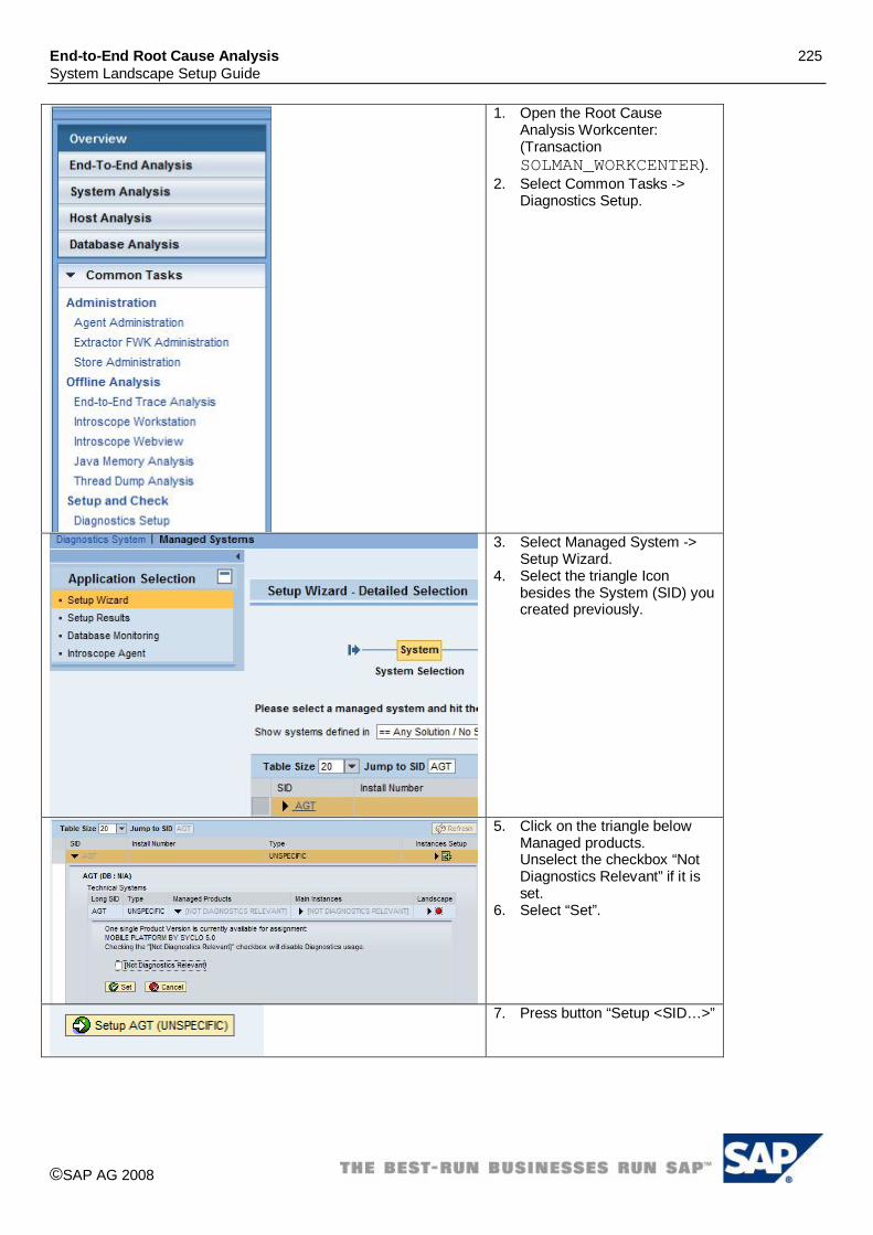
End-to-End Root Cause Analysis 225 System Landscape Setup Guide
©SAP AG 2008
1. Open the Root Cause Analysis Workcenter: (Transaction SOLMAN_WORKCENTER).
2. Select Common Tasks -> Diagnostics Setup.
3. Select Managed System -> Setup Wizard.
4. Select the triangle Icon besides the System (SID) you created previously.
5. Click on the triangle below Managed products. Unselect the checkbox “Not Diagnostics Relevant” if it is set.
6. Select “Set”.
7. Press button “Setup <SID…>”

End-to-End Root Cause Analysis 226 System Landscape Setup Guide
©SAP AG 2008
17. Enter the Installation Path for Agentry Server. E.g. “D:\Agentry\ServerProd”
18. Select “Set”.
19. Select the checkbox besides the server name.
20. Select Next.
21. Select Setup.
22. After some seconds the setup should be finished with green or at least yellow lights.
4.47.4 Additional configuration steps Please enable Process Monitoring for the Agentry Server as described in SAP Note 1371097.

End-to-End Root Cause Analysis 227 System Landscape Setup Guide
©SAP AG 2008
4.48 SAP BPC 5.1/7.0/for Microsoft For SAP BPC 5.1 and SAP BPC 7.0 for Microsoft an automated creation of the technical system via the SLD is currently not supported. Therefore you have to enter the BPC system landscape information manually using transaction SMSY. Afterwards perform the Diagnostics Configuration for the BPC system using the “Diagnostics Setup” wizard.
4.48.1 Manual creation of technical systems for SAP BPC 5.1/7.0/for Microsoft
23. Call transaction “SMSY”. 24. Repeat the steps 3-8 for all
servers which are not yet maintained in SMSY and which run software components of your BPC system (BPC Web Servers, BPC Application Servers, Microsoft Analysis Services, Microsoft Reporting Services, Microsoft Integration Services, SQL Server Database):
25. Right-click on Server. 26. Select “Create New Server”.
27. Enter the server name where your BPC Server is installed.
28. Press Save
29. Maintain at least the fields “Fully-Qualified Host Name” and “IP-Address”.
30. Select “Save”.

End-to-End Root Cause Analysis 228 System Landscape Setup Guide
©SAP AG 2008
31. Right-click on Database. 32. Select “Create New
Database”.
33. Enter the System ID of your BPC system as Database name.
34. Select “Save”. Please note: BPC systems are not installed with a System ID, however, in order to identify the system in Diagnostics you need to make up and enter a system ID here.
35. Select SQL Server in field Manufacturer.
36. Select the Server installed the SQL Server database.
37. Select “Save”.
38. Right-click on System Components.
39. Select “Create New System Component”.
40. Enter the System ID of your BPC system as System Component name.
41. Select type “MS.Net”. 42. You can leave the field
Installation Number free. 43. Select “Save”. Please note: 44. BPC systems are not
installed with a System ID, however, in order to identify the system in Diagnostics you need to make up and enter a unique system ID here.

End-to-End Root Cause Analysis 229 System Landscape Setup Guide
©SAP AG 2008
45. Select tab “Header Data” 46. Select Flag “Production” 47. Select the Database you
maintained previously.
48. Select tab “Instances” 49. Repeat the following for each
server (host) where BPC Application Servers, Web Servers, Microsoft Reporting Services, Microsoft Analysis Services and Microsoft Integration Services are installed:
50. Add a new line. 51. Select the Server in field
“Server”. 52. Maintain the Instance Name
according to the following naming convention: <Server Name>_<System ID>
53. Select tab “Software Components”
54. Select button: “Copy Software Component from Main Instance”
55. Select Product “SAP BPC FOR MICROSOFT”.
56. Select the correct Product Version.
57. Select Main Instance “BPC Server”.
58. Select “Continue (Enter)”

End-to-End Root Cause Analysis 230 System Landscape Setup Guide
©SAP AG 2008
59. Select button: “Copy Software Component from Main Instance”
60. Select Product “MS IIS”. 61. Select the correct IIS Version. 62. Select Main Instance “MS
IIS”. 63. Select “Continue (Enter)” Please note: If your system is running on Windows 2003 Servers, the correct MS IIS Version is probably 6.0. In case of Windows Server 2008 it is 7.0.
64. Select button: “Copy Software Component from Main Instance”
65. Select Product “MSFT.NET”. 66. Select the Version
“MSFT.NET 1.1” 67. Select Main Instance
“MSFT.NET Framework” Select “Continue (Enter)”
68. Press button “Save”
69. Right-click on Systems. 70. Select “Create New System”.

End-to-End Root Cause Analysis 231 System Landscape Setup Guide
©SAP AG 2008
71. Enter the System ID of your BPC system.
72. Select product “SAP BPC FOR MICROSOFT”.
73. Select the correct Product Version.
74. You can leave the field Installation Number free.
75. Select “Save” Please note: BPC systems are not installed with a System ID, however, in order to identify the system in Diagnostics you need to make up and enter a unique system ID here.
76. Select tab “Selection of Main Instances”.
77. Select flags “Relevant” and “System Component” for the Main Instance “BPC Server”.
78. Assign the System Component defined above and select the Type “MS. Net”.
79. Select “Save”.
80. Select tab “Header Data”. 81. Select button “Installed
Product Versions”. 82. Select Flag “Free
Product/Select Product version”.
83. Select Product “MSFT.NET” and Product Version “MSFT.NET 1.1”
84. Select “Copy” and confirm the popups.
85. Select Product “MS IIS” and the version of MS IIS you use”
86. Select “Copy” and confirm the popups.
87. Ensure that flag “Leading Product Version” is not set for any Product.
88. Select “Save”. Please note: If your system is running on Windows 2003 Servers, the correct MS IIS Version is probably 6.0. In case of Windows Server 2008 it is 7.0.

End-to-End Root Cause Analysis 232 System Landscape Setup Guide
©SAP AG 2008
89. In the Landscape Components section to the left expand “Systems” -> “MS IIS” tree and select the system you created.
90. Select tab “Selection of Main Instances”.
91. Select flags “Relevant” and “System Component” for the Main Instance “MS IIS”.
92. Assign the System Component defined above and select the Type “MS. Net”.
93. Select “Save”.
94. In the Landscape Components section to the left expand “Systems” -> “MSFT.NET” tree and select the system you created previously.
95. Select tab “Selection of Main Instances”.
96. Select flags “Relevant” and “System Component” for the Main Instance “MSFT.NET”.
97. Assign the System Component defined above and select the Type “MS. Net”.
98. Select “Save”.
4.48.2 Installation of Diagnostic Agents If not already done so, SAP Host Control and a Diagnostics Agent needs to be installed on all servers (hosts) where BPC Application Servers, Web Servers, Microsoft Reporting Services, Microsoft Analysis Services and Microsoft Integration Services are installed. Please refer to SAP Note 1234387.
4.48.3 Diagnostics Configuration After setting up the technical system and installation of the Diagnostics Agents, the configuration steps need to be performed.

End-to-End Root Cause Analysis 233 System Landscape Setup Guide
©SAP AG 2008
8. Open the Root Cause Analysis Work Center (Transaction: SOLMAN_Workcenter).
9. Expand section “Common Tasks”.
10. Select “Diagnostics Setup”.
11. Select “Managed Systems” -> “Setup Wizard”.
12. Select the system you created before.

End-to-End Root Cause Analysis 234 System Landscape Setup Guide
©SAP AG 2008
13. Select the triangle below Managed products. Unselect the checkbox “Not Diagnostics Relevant” if it is set.
14. Select (highlight) the following Products to be managed by Diagnostics: MS IIS <XX>, MSFT .Net <XX>, SAP BPC <XX> if they are not already highlighted.
15. Select “Set” if you had to change anything otherwise “Cancel”.
16. Select the triangle below Main Instances.
17. Select (highlight) the following Main Instances to be managed by Diagnostics: MS IIS, MSFT .Net Framework, BPC Server or BPC .net Server if they are not already highlighted.
18. Select “Set” if you had to change anything otherwise “Cancel”.
19.
20. Press button “Setup <SID…>”
21. Specify Installation Path for BPC Server.
22. Specify Software Component Paths for MS IIS, MSFT .Net Framework and BPC Server.
23. Select Next.

End-to-End Root Cause Analysis 235 System Landscape Setup Guide
©SAP AG 2008
24. Select Setup.
25. After some seconds the setup should be finished with green or at least yellow lights.
4.48.4 BPC specific configuration of Wily Agents The collection of performance counters for BPC and IIS/.net needs to be enabled. Therefore please refer to SAP Note 1328011 to perform the Configuration of SMD Host agent and CA Wily Introscope .Net Agent.
4.48.5 Configuration of Remote Database Monitoring Please refer to SAP Note 1388700. Please note: For Microsoft SQL Server, the DBsl and the client software are provided exclusively for the Windows operating system. UNIX/Linux-based Solution Manager Systems require a separate application server on Windows to enable you to connect an SQL Server database.
4.49 SAP BPC 7.0 for SAP Netweaver The system landscape for SAP BPC for Netweaver consists out of at least one BPC .NET Server and one Business Plan.and Cons. ABAP stack. For the BPC .NET Server an automated creation of the technical system via the SLD is currently not supported. Therefore you have to enter the BPC system landscape information manually using transaction SMSY. Afterwards perform the Diagnostics Configuration for the BPC system using the “Diagnostics Setup” wizard.
4.49.1 Manual creation of technical systems for the BPC .NET Server
1. Call transaction “SMSY”. 2. Repeat the steps 3-8 for all
servers which are not yet maintained in SMSY and which run software components of your BPC system (BPC Web Servers, BPC Application Servers).
3. Right-click on Server. 4. Select “Create New Server”.

End-to-End Root Cause Analysis 236 System Landscape Setup Guide
©SAP AG 2008
5. Enter the server name where your BPC Server is installed.
6. Press Save.
7. Maintain at least the fields “Fully-Qualified Host Name” and “IP-Address”.
8. Select “Save”.
9. Right-click on System Components.
10. Select “Create New System Component”.
11. Enter the System ID of your BPC system as System Component name.
12. Select type “MS.Net”. 13. You can leave the field
Installation Number free. 14. Select “Save”. Please note: The .Net Web/Application servers are not installed with a System ID; however, in order to identify the system in Diagnostics you need to enter a system ID here We would recommend using the same system id as the SAP NetWeaver Application Server.

End-to-End Root Cause Analysis 237 System Landscape Setup Guide
©SAP AG 2008
15. Select tab “Header Data” 16. Select Flag “Production”
17. Select tab “Instances” 18. Repeat the following for each
server (host) where BPC Application Servers and Web Servers are installed:
19. Add a new line. 20. Select the Server in field
“Server”. 21. Maintain the Instance Name
according to the following naming convention: <Server Name>_<System ID>
22. Select tab “Software Components”
23. Select button: “Copy Software Component from Main Instance”
24. Select Product “SAP BPC FOR SAP NETWEAVER”.
25. Select the correct Product Version.
26. Select Main Instance “BPC .NET Server”.
27. Select “Continue (Enter)”
28. Select button: “Copy Software Component from Main Instance”
29. Select Product “MS IIS”. 30. Select the correct IIS Version. 31. Select Main Instance “MS
IIS”. 32. Select “Continue (Enter)” Please note: If your system is running on Windows 2003 Servers, the correct MS IIS Version is probably 6.0. In case of Windows Server 2008 it is 7.0.

End-to-End Root Cause Analysis 238 System Landscape Setup Guide
©SAP AG 2008
33. Select button: “Copy Software Component from Main Instance”
34. Select Product “MSFT.NET”. 35. Select the Version
“MSFT.NET 1.1” 36. Select Main Instance
“MSFT.NET Framework” Select “Continue (Enter)”
37. Press button “Save”
38. Right-click on Systems. 39. Select “Create New System”.
40. Enter the System ID of your BPC system.
41. Select product “SAP BPC FOR NETWEAVER”.
42. Select the correct Product Version.
43. You can leave the field Installation Number free.
44. Select “Save”
45. Select tab “Selection of Main Instances”.
46. Select flags “Relevant” and “System Component” for the Main Instance “BPC Server”.
47. Assign the System Component defined above and select the Type “MS. Net”.
48. Select “Save”.

End-to-End Root Cause Analysis 239 System Landscape Setup Guide
©SAP AG 2008
49. Select tab “Header Data”. 50. Select button “Installed
Product Versions”. 51. Select Flag “Free
Product/Select Product version”.
52. Select Product “MSFT.NET” and Product Version “MSFT.NET 1.1”
53. Select “Copy” and confirm the popup.
54. Select Product “MS IIS” and the version of MS IIS you use”
55. Select “Copy” and confirm the popup.
56. Ensure that flag “Leading Product Version” is not set for any Product.
57. Select “Save”. Please note: If your system is running on Windows 2003 Servers, the correct MS IIS Version is probably 6.0. In case of Windows Server 2008 it is 7.0.
58. In the Landscape Components section expand “Systems” -> “MS IIS” tree and select the system you created.
59. Select tab “Selection of Main Instances”.
60. Select flags “Relevant” and “System Component” for the Main Instance “MS IIS”.
61. Assign the System Component defined above and select the Type “MS. Net”.
62. Select “Save”.
63. In the Landscape Components section expand “Systems” -> “MSFT.NET” tree and select the system you created previously.
64. Select tab “Selection of Main Instances”.
65. Select flags “Relevant” and “System Component” for the Main Instance “MSFT.NET”.
66. Assign the System Component defined above and select the Type “MS.

End-to-End Root Cause Analysis 240 System Landscape Setup Guide
©SAP AG 2008
Net”. 67. Select “Save”.
4.49.2 Creation of technical systems for the BPC ABAP stack The data necessary for the SLD are collected via the data supplier available in ABAP. Start the configuration of the System Landscape Directory (Transaction RZ70) and send the collected data to your System Landscape Directory. Afterwards some adjustment in transaction SMSY in Solution Manager is necessary.
1. Start the configuration of the System Landscape Directory in Transaction RZ70 in the BPC ABAP stack.
2. Enter your SLD connection information.
3. Activate the settings.

End-to-End Root Cause Analysis 241 System Landscape Setup Guide
©SAP AG 2008
4. Start Transaction SMSY in SAP Solution Manager.
5. In the Landscape Components section to the left expand the “Systems” -> “SAP Netweaver” tree and select the system reported into SLD.
Please note: If the system was reported to SLD recently, it might only appear in SMSY after the next run of the Landscape fetch job.
6. Select tab “Selection of Main Instances”.
7. Select the Main Instance “Business Intelligence” as relevant.
8. Select “Save”

End-to-End Root Cause Analysis 242 System Landscape Setup Guide
©SAP AG 2008
9. Select tab “Header Data”. 10. Select button “Installed
Product Versions”. 11. Select Flag “Free
Product/Select Product version”.
12. Select Product “SAP BPC FOR SAP NETWEAVER” and the correct Product Version “.
13. Select “Copy” and confirm the popup.
14. Ensure that flag “Leading Product Version” is not set for any Product.
15. Select “Save”.
16. In the Landscape Components section to the left expand the “Systems” -> “SAP BPC FOR SAP NETWEAVER” tree and select the system.
17. Select tab “Selection of Main Instances”.
18. Select the Main Instance “Business Plan.and Cons. ABAP” as relevant.
19. Select “Save”

End-to-End Root Cause Analysis 243 System Landscape Setup Guide
©SAP AG 2008
20. In the Landscape Components section to the left select the Main Instance “Business Plan.and Cons. ABAP”.
21. Select tab “Clients” on the right screen, mark the relevant client and generate a read RFC destination using the RFC generation wizard. In the wizard unselect all options but “RFC Destination and User for Read Access”.
4.49.3 Installation of Diagnostic Agents If not already done so, SAP Host Control and a Diagnostics Agent needs to be installed on all servers (hosts) where BPC Application Servers, Web Servers and BPC ABAP Stack are installed. Please refer to SAP Note 1234387.
4.49.4 Diagnostics Configuration for BPC .NET Server After setting up the technical system and installation of the Diagnostics Agents, the configuration steps need to be performed.

End-to-End Root Cause Analysis 244 System Landscape Setup Guide
©SAP AG 2008
1. Open the Root Cause Analysis Work Center (Transaction: SOLMAN_Workcenter).
2. Expand section “Common Tasks”.
3. Select “Diagnostics Setup”.
4. Select “Managed Systems” -> “Setup Wizard”.
5. Select the system you created before.

End-to-End Root Cause Analysis 245 System Landscape Setup Guide
©SAP AG 2008
6. Select the triangle below Managed products. Unselect the checkbox “Not Diagnostics Relevant” if it is set.
7. Select (highlight) the following Products to be managed by Diagnostics: MS IIS <XX>, MSFT .Net <XX>, SAP BPC <XX> if they are not already highlighted.
8. Select “Set” if you had to change anything otherwise “Cancel”.
9. Select the triangle below Main Instances.
10. Select (highlight) the following Main Instances to be managed by Diagnostics: MS IIS, MSFT .Net Framework, BPC .net Server if they are not already highlighted.
11. Select “Set” if you had to change anything otherwise “Cancel”.
12.
13. Press button “Setup <SID…>”
14. Specify Installation Path for BPC Server.
15. Specify Software Component Paths for MS IIS, MSFT .Net Framework and BPC Server.
16. Select “Set”.
17. Select Next.

End-to-End Root Cause Analysis 246 System Landscape Setup Guide
©SAP AG 2008
18. Select Setup.
19. After some seconds the setup should be finished with green or at least yellow lights.
4.49.5 BPC specific configuration of Wily Agents for BPC .NET Server The collection of performance counters for BPC and IIS/.net needs to be enabled. Therefore please refer to SAP Note 1343071 to perform the Configuration of SMD Host Agent and CA Wily Introscope .Net Agent.
4.49.6 Diagnostics Configuration for BPC ABAP stack For BPC ABAP Stack the procedure described for the “Managed System Configuration” needs to be followed. Please refer to chapter 2.2.
4.50 SBOP PC 7.5 FOR SAP NW Prerequisite for the Diagnostics Setup of SBOP PC 7.5 FOR SAP NW is that the SAP Solution Manager is based on Version 7.0 EHP 1 SP23 or higher. The system landscape the product version SBOP PC 7.5 FOR SAP NW consists out of at least one BPC .NET Server and one Business Plan. and Cons. ABAP stack. For the BPC .NET Server an automated creation of the technical system via the SLD is currently not supported. Therefore you have to enter the BPC system landscape information manually using transaction SMSY. Afterwards perform the Diagnostics Configuration for the BPC system using the “Diagnostics Setup” wizard.
4.50.1 Manual creation of technical systems for the BPC .NET Server
1. Call transaction “SMSY”. 2. Repeat the steps 3-8 for all
servers which are not yet maintained in SMSY and which run software components of your BPC system (BPC Web Servers, BPC Application Servers).

End-to-End Root Cause Analysis 247 System Landscape Setup Guide
©SAP AG 2008
3. Right-click on Server. 4. Select “Create New Server”.
5. Enter the server name where your BPC Server is installed.
6. Press Save.
7. Maintain at least the fields “Fully-Qualified Host Name” and “IP-Address”.
8. Select “Save”.
9. Right-click on System Components.
10. Select “Create New System Component”.
11. Enter the System ID of your BPC system as System Component name.
12. Select type “MS.Net”. 13. You can leave the field
Installation Number free. 14. Select “Save”. Please note: The BPC .Net Web/Application servers are not installed with a System ID; however, in order to identify the system in Diagnostics you need to enter a system ID here. Please use the same system id as the Business Plan.and Cons. ABAP stack.
15. Select tab “Header Data” 16. Select Flag “Production”

End-to-End Root Cause Analysis 248 System Landscape Setup Guide
©SAP AG 2008
17. Select tab “Instances” 18. Repeat the following for each
server (host) where BPC Application Servers and Web Servers are installed:
19. Add a new line. 20. Select the Server in field
“Server”. 21. Maintain the Instance Name
according to the following naming convention: <Server Name>_<System ID>
22. Select tab “Software Components”
23. Select button: “Copy Software Component from Main Instance”
24. Select Product “SAP BPC FOR SAP NETWEAVER”.
25. Select the correct Product Version.
26. Select Main Instance “BPC .NET Server”.
27. Select “Continue (Enter)”
28. Select button: “Copy Software Component from Main Instance”
29. Select Product “MS IIS”. 30. Select the correct IIS Version. 31. Select Main Instance “MS
IIS”. 32. Select “Continue (Enter)” Please note: If your system is running on Windows 2003 Servers, the correct MS IIS Version is probably 6.0. In case of Windows Server 2008 it is 7.0.
33. Select button: “Copy Software Component from Main Instance”
34. Select Product “MSFT.NET”. 35. Select the Version
“MSFT.NET 1.1” 36. Select Main Instance
“MSFT.NET Framework” Select “Continue (Enter)”

End-to-End Root Cause Analysis 249 System Landscape Setup Guide
©SAP AG 2008
37. Press button “Save”
87. Right-click on Systems. 88. Select “Create New System”.
38. Enter the System ID of your BPC system + Suffix (e.g _NET) to differentiate from the System ID of the BPC ABAP Stack.
40. Select product “SAP BPC FOR NETWEAVER”.
41. Select the correct Product Version.
42. You can leave the field Installation Number free.
43. Select “Save”
44. Select tab “Selection of Main Instances”.
45. Select flags “Relevant” and “System Component” for the Main Instance “BPC Server”.
46. Assign the System Component defined above and select the Type “MS. Net”.
47. Select “Save”.

End-to-End Root Cause Analysis 250 System Landscape Setup Guide
©SAP AG 2008
48. Select tab “Header Data”. 49. Select button “Change
Product Assignment”. 50. Select Flag “Free
Product/Select Product version”.
51. Select Product “MSFT.NET” and Product Version “MSFT.NET 1.1”
52. Select “Copy” and confirm the popup.
53. Select Product “MS IIS” and the version of MS IIS you use”
54. Select “Copy” and confirm the popup.
55. Ensure that flag “Active” is set for all 3 products.
56. Ensure that flag “Active” is set for all 3 products.
57. Select “Save”. Please note: If your system is running on Windows 2003 Servers, the correct MS IIS Version is probably 6.0. In case of Windows Server 2008 it is 7.0.
58. Select flag “Production”.
59. In the Landscape Components section expand “Systems” -> “MS IIS” tree and select the system you created.
60. Select tab “Selection of Main Instances”.
61. Select flags “Relevant” and “System Component” for the Main Instance “MS IIS”.
62. Assign the System Component defined above and select the Type “MS.

End-to-End Root Cause Analysis 251 System Landscape Setup Guide
©SAP AG 2008
Net”. 63. Select “Save”.
64. In the Landscape Components section expand “Systems” -> “MSFT.NET” tree and select the system you created previously.
65. Select tab “Selection of Main Instances”.
66. Select flags “Relevant” and “System Component” for the Main Instance “MSFT.NET”.
67. Assign the System Component defined above and select the Type “MS. Net”.
68. Select “Save”.
4.50.2 Creation of technical systems for the BPC ABAP stack The data necessary for the SLD are collected via the data supplier available in ABAP. Start the configuration of the System Landscape Directory (Transaction RZ70) and send the collected data to your System Landscape Directory..
1. Start the configuration of the System Landscape Directory in Transaction RZ70 in the BPC ABAP system.

End-to-End Root Cause Analysis 252 System Landscape Setup Guide
©SAP AG 2008
2. Enter your SLD connection information.
3. Activate the settings.
4. Start Transaction SMSY in SAP Solution Manager.
5. In the Landscape Components section to the left expand the “Systems” -> “SAP Netweaver” tree and select the BPC ABAP System reported into SLD.
Please note: If the system was reported to SLD recently, it might only appear in SMSY after the next run of the Landscape fetch job.
6. Select tab “Header Data”. 7. Select button “Installed
Product Versions”. 8. Select Flag “Free
Product/Select Product version”.
9. Select Product “SAP BPC FOR SAP NETWEAVER” and the correct Product Version “.
10. Select “Copy” and confirm the popup.
11. Select Product “SAP NETWEAVER” and the correct Product Version “.
12. Select “Copy” and confirm the popup.
13. Ensure that flag “Active” is set for “SAP BPC FOR SAP NETWEAVER” and “SAP NETWEAVER”.
14. Select “Save”.

End-to-End Root Cause Analysis 253 System Landscape Setup Guide
©SAP AG 2008
15. Select tab “Selection of Main Instances”.
16. Select the Main Instance “Business Intelligence” as relevant.
17. Select “Save”
18. In the Landscape Components section to the left expand the “Systems” -> “SAP BPC FOR SAP NETWEAVER” tree and select the BPC ABAP System reported into SLD.
19. Select tab “Selection of Main Instances”.
20. Select the Main Instance “Business Plan. and Cons. ABAP” as relevant.
21. Select “Save”
22. Double-click on Main Instance “Business Plan. and Cons. ABAP”.
23. Select tab “Clients” on the right screen, mark the relevant client.
24. Press button “Generate RFC Destinations”. In the wizard unselect all options but “RFC Destination and User for Read Access”.
4.50.3 Installation of Diagnostic Agents If not already done so, SAP Host Control and a Diagnostics Agent needs to be installed on all servers (hosts) where BPC Application Servers, Web Servers and BPC ABAP Stack are installed. Please refer to SAP Note 1234387. After Diagnostics Agent installation, assign the Diagnostics Agent user to the local user group “Performance Monitor Users" as described in SAP Note 1234387 section “Post-Installation”.

End-to-End Root Cause Analysis 254 System Landscape Setup Guide
©SAP AG 2008
4.50.4 Installation of Wily Introscope .NET Agent The collection of Wily Introscope performance metrics for BPC Servers needs to be enabled. Please refer to SAP Note 1126554 to install CA Wily Introscope .Net Agent on all BPC .net Servers.
4.50.5 Diagnostics Configuration for BPC .NET Server After setting up the technical system and installation of the Diagnostics Agents, the configuration steps need to be performed.
1. Open the Root Cause Analysis Work Center (Transaction: SOLMAN_Workcenter).
2. Expand section “Common Tasks”.
3. Select “Diagnostics Setup”.
4. Select “Managed Systems” -> “Setup Wizard”.
5. Select the system you created before.

End-to-End Root Cause Analysis 255 System Landscape Setup Guide
©SAP AG 2008
6. Select the triangle below Managed products. Unselect the checkbox “Not Diagnostics Relevant” if it is set.
7. Select (highlight) the following Products to be managed by Diagnostics: MS IIS <XX>, MSFT .Net <XX>, SBOB PC <XX> if they are not already highlighted.
8. Select “Set” if you had to change anything otherwise “Cancel”.
9. Select the triangle below Main Instances.
10. Select (highlight) the following Main Instances to be managed by Diagnostics: MS IIS, MSFT .Net Framework, BPC .net Server if they are not already highlighted.
11. Select “Set” if you had to change anything otherwise “Cancel”.
12. Press button “Setup <SID…>”
13. Specify Installation Path for BPC Server.
14. Specify Software Component Paths for MS IIS, MSFT .Net Framework and BPC Server.
15. Select “Set”.

End-to-End Root Cause Analysis 256 System Landscape Setup Guide
©SAP AG 2008
16. Select Next.
17. Select Setup.
18. After some seconds the setup should be finished with green or at least yellow lights.
4.50.6 Diagnostics Configuration for BPC ABAP stack For BPC ABAP Stack the procedure described for the “Managed System Configuration” needs to be followed. Please refer to chapter 2.2. During setup, mark the managed products “SAP EHP1 for SAP Netweaver 7.0” and “SBOP PC 7.5 FOR SAP NETWEAVER” as diagnostics relevant. During setup, mark the main instances “Business Intelligence” and “SBOP PC 7.5 FOR SAP NETWEAVER” as diagnostics relevant.
4.51 SBOP PC 7.5 for Microsoft For SBOP PC 7.5 for Microsoft an automated creation of the technical system via the SLD is currently not supported. Therefore you have to enter the BPC system landscape information manually using transaction SMSY. Afterwards perform the Diagnostics Configuration for the BPC system using the “Diagnostics Setup” wizard.
4.51.1 Manual creation of technical systems for SBOP PC 7.5 for Microsoft 4.51.2 Hosts and database

End-to-End Root Cause Analysis 257 System Landscape Setup Guide
©SAP AG 2008
1. Call transaction “SMSY”. 2. Repeat the steps 3-8 for all
servers which are not yet maintained in SMSY and which run software components of your BPC system (BPC Web Servers, BPC Application Servers, Microsoft Analysis Services, Microsoft Reporting Services, Microsoft Integration Services, SQL Server Database):
3. Right-click on Server. 4. Select “Create New Server”.
5. Enter the server name where your BPC Server is installed.
6. Press Save
7. Maintain at least the fields “Fully-Qualified Host Name” and “IP-Address”.
8. Select “Save”.
9. Right-click on Database. 10. Select “Create New
Database”.
11. Enter the System ID of your BPC system as Database name.
12. Select “Save”. Please note: BPC systems are not installed with a System ID, however, in order to identify the system in Diagnostics you need to make up and enter a system ID here.

End-to-End Root Cause Analysis 258 System Landscape Setup Guide
©SAP AG 2008
13. Select SQL Server in field Manufacturer.
14. Select the Server where the SQL Server database is installed.
15. Select “Save”.
4.51.3 System Component for BPC .net Server
1. Right-click on System Components.
2. Select “Create New System Component”.
3. Enter the System ID of your BPC system as System Component name.
4. Select type “MS.Net”. 5. You can leave the field
Installation Number free. 6. Select “Save”. Please note: BPC systems are not installed with a System ID, however, in order to identify the system in Diagnostics you need to make up and enter a unique system ID here.
7. Select tab “Header Data” 8. Select Flag “Production” 9. Enter the Database you
maintained previously.

End-to-End Root Cause Analysis 259 System Landscape Setup Guide
©SAP AG 2008
10. Select tab “Instances” 11. Repeat the following for each
server (host) where BPC Application Servers are installed:
12. Add a new line. 13. Select the Server in field
“Server”. 14. Maintain the Instance Name
according to the following naming convention: <Server Name>_<System ID>
15. Select tab “Software Components”
16. Select button: “Copy Software Component from Main Instance”
17. Select Product “SAP BPC FOR MICROSOFT”.
18. Select the correct Product Version.
19. Select Main Instance “BPC Server”.
20. Select “Continue (Enter)”
21. Select button: “Copy Software Component from Main Instance”
22. Select Product “MS IIS”. 23. Select the correct IIS Version. 24. Select Main Instance “MS
IIS”. 25. Select “Continue (Enter)” Please note: If your system is running on Windows 2003 Servers, the correct MS IIS Version is probably 6.0. In case of Windows Server 2008 it is 7.0.

End-to-End Root Cause Analysis 260 System Landscape Setup Guide
©SAP AG 2008
26. Select button: “Copy Software Component from Main Instance”
27. Select Product “MSFT.NET”. 28. Select the Version
“MSFT.NET 2.0” 29. Select Main Instance
“MSFT.NET Framework” Select “Continue (Enter)”
30. Press button “Save”
4.51.4 System Component for Microsoft SQL Server Analysis Services
1. Right-click on System Components.
2. Select “Create New System Component”.
3. Enter <System ID>_SSAS (for example) as System Component name.
4. Select type “MS.Net”. 5. You can leave the field
Installation Number free. 6. Select “Save”.
7. Select tab “Header Data” 8. Select Flag “Production”

End-to-End Root Cause Analysis 261 System Landscape Setup Guide
©SAP AG 2008
9. Select tab “Instances” 10. Repeat the following for each
server (host) where Microsoft Analysis Services are installed:
11. Add a new line. 12. Select the Server in field
“Server”. 13. Maintain the Instance Name
according to the following naming convention: <Server Name>_<System ID>
14. Select tab “Software Components”
15. Select button: “Copy Software Component from Main Instance”
16. Select Product “SAP BPC FOR MICROSOFT”.
17. Select the correct Product Version.
18. Select Main Instance “MS SQL Server Analysis Service”.
19. Select “Continue (Enter)”.
20. Press button “Save”.
4.51.5 System Component for Microsoft SQL Server Reporting Services
1. Right-click on System Components.
2. Select “Create New System Component”.

End-to-End Root Cause Analysis 262 System Landscape Setup Guide
©SAP AG 2008
3. Enter <System ID>_SSRS (for example) as System Component name.
4. Select type “MS.Net”. 5. You can leave the field
Installation Number free. 6. Select “Save”.
7. Select tab “Header Data” 8. Select Flag “Production”
9. Select tab “Instances” 10. Repeat the following for each
server (host) where Microsoft Reporting Services are installed:
11. Add a new line. 12. Select the Server in field
“Server”. 13. Maintain the Instance Name
according to the following naming convention: <Server Name>_<System ID>
14. Select tab “Software Components”
15. Select button: “Copy Software Component from Main Instance”
16. Select Product “SAP BPC FOR MICROSOFT”.
17. Select the correct Product Version.
18. Select Main Instance “MS SQL Server Reporting Service”.
19. Select “Continue (Enter)”.

End-to-End Root Cause Analysis 263 System Landscape Setup Guide
©SAP AG 2008
20. Press button “Save”.
4.51.6 System Component for Microsoft SQL Server Integration Services
1. Right-click on System Components.
2. Select “Create New System Component”.
3. Enter <System ID>_SSIS (for example) as System Component name.
4. Select type “MS.Net”. 5. You can leave the field
Installation Number free. 6. Select “Save”.
7. Select tab “Header Data” 8. Select Flag “Production”

End-to-End Root Cause Analysis 264 System Landscape Setup Guide
©SAP AG 2008
9. Select tab “Instances” 10. Repeat the following for each
server (host) where Microsoft Integration Services are installed:
11. Add a new line. 12. Select the Server in field
“Server”. 13. Maintain the Instance Name
according to the following naming convention: <Server Name>_<System ID>
14. Select tab “Software Components”
15. Select button: “Copy Software Component from Main Instance”
16. Select Product “SAP BPC FOR MICROSOFT”.
17. Select the correct Product Version.
18. Select Main Instance “MS SQL Server Integration Service”.
19. Select “Continue (Enter)”.
20. Press button “Save”.
4.51.7 BPC System
1. Right-click on Systems. 2. Select “Create New System”.

End-to-End Root Cause Analysis 265 System Landscape Setup Guide
©SAP AG 2008
3. Enter the System ID of your BPC system.
4. Select product “SAP BPC FOR MICROSOFT”.
5. Select the correct Product Version.
6. You can leave the field Installation Number free.
7. Select “Save” Please note: BPC systems are not installed with a System ID, however, in order to identify the system in Diagnostics you need to make up and enter a unique system ID here.
8. Select tab “Selection of Main Instances”.
9. Select flags “Relevant” and “System Component” for the Main Instance “BPC Server”.
10. Assign the System Component defined above for the BPC server and select the Type “MS. Net”.
11. Select flags “Relevant” and “System Component” for the Main Instance “MS SQL Server Analysis Services”.
12. Assign the System Component defined above for the MS SQL Server Analysis Services and select the Type “MS. Net”.
13. Select flags “Relevant” and “System Component” for the Main Instance “MS SQL Integration Services”.
14. Assign the System Component defined above for the MS SQL Server Integration Services and select the Type “MS. Net”.

End-to-End Root Cause Analysis 266 System Landscape Setup Guide
©SAP AG 2008
15. Select flags “Relevant” and “System Component” for the Main Instance “MS SQL Reporting Services”.
16. Assign the System Component defined above for the MS SQL Server Reporting Services and select the Type “MS. Net”.
17. Select “Save”.
18. Select tab “Header Data”. 19. Select Flag “Production”. 20. Select “Save”. 21. Select button “Change
Product Assignment”.
22. Select Flag “Free Product/Select Product version”.
23. Select Product “MSFT.NET” and Product Version “MSFT.NET 1.1”
24. Select “Copy” and confirm the pop-ups.
25. Select Product “MS IIS” and the version of MS IIS you use”
26. Select “Copy” and confirm the pop-ups.
27. Ensure that flag “Active” is set for all 3 products.
28. Select “Save”. Please note: 29. If your system is running on
Windows 2003 Servers, the correct MS IIS Version is probably 6.0. In case of Windows Server 2008 it is 7.0.

End-to-End Root Cause Analysis 267 System Landscape Setup Guide
©SAP AG 2008
4.51.8 Installation of Diagnostic Agents If not already done so, SAP Host Control and a Diagnostics Agent needs to be installed on all servers (hosts) where BPC Application Servers, Web Servers, Microsoft Reporting Services, Microsoft Analysis Services and Microsoft Integration Services are installed. Please refer to SAP Note 1234387. The following post processing steps are required after Diagnostics Agent installation on the servers:
4.51.9 Enable Diagnostics Agents to read Windows Performance Monitor Data By default the Diagnostics Agent is not allowed to read Windows Performance Monitor Data from WMI. Please perform the following steps to enable the collection of Windows Performance Monitor Data: Assign the Diagnostics Agent user SAPService<DASID> to the local user group “Performance Monitor Users" as described in SAP Note 1234387 section “Post-Installation”. Afterwards restart the SAP<SID>_<Instno> Service (e.g. SAPDAA_97).
4.51.10 Enable Diagnostics Agents to read Configuration and Log data from Microsoft SQL Server Components
By default the Diagnostics Agent is not allowed to access the directories where Configuration and Log data of Microsoft Reporting Services and Microsoft Analysis Services are stored. Please perform the following steps to enable the collection of Configuration Data and access to logs for these software components:
1. Start Windows explorer and navigate to the directory where Microsoft Analysis Service is installed. (E.g. D:\Program Files\ Microsoft SQL Server\ MSSQL.3\ Reporting Services)
2. Right-click on the Reporting Services folder and select Properties. The Properties window for the folder is displayed.
3. Select tab Security. 4. Select Add.
5. Select location <localhost>. 6. Enter user
SAPService<DASID>. 7. Select OK.

End-to-End Root Cause Analysis 268 System Landscape Setup Guide
©SAP AG 2008
8. Verify that the user SAPService<DASID>has the following permissions: - Read & Execute - List Folder Contents - Read.
9. Click the Advanced button. The Advanced Security Settings for OLAP dialogue box is displayed.
10. Select User SAPService<DASID>.
11. Click the “Replace permission entries on all child objects with entries shown here that apply to child objects” check box to propagate permissions to the child directories, and
12. Click OK.
13. Navigate to the directory where Microsoft Reporting Service is installed. (E.g. D:\Program Files\Microsoft SQL Server\MSSQL.2\OLAP)
14. Right-click on the OLAP folder and select Properties. The Properties window for the folder is displayed.
15. Select tab Security. 16. Select Add.
17. Select location <localhost>. 18. Enter user
SAPService<DASID>. 19. Select OK.

End-to-End Root Cause Analysis 269 System Landscape Setup Guide
©SAP AG 2008
20. Verify that the user SAPService<DASID>has the following permissions: - Read & Execute - List Folder Contents - Read.
21. Click the Advanced button. The Advanced Security Settings for OLAP dialogue box is displayed.
22. Select User SAPService<DASID>.
23. Click the “Replace permission entries on all child objects with entries shown here that apply to child objects” check box to propagate permissions to the child directories, and
24. Click OK.
4.51.11 Installation of Wily Introscope .NET Agent The collection of Wily Introscope performance metrics for BPC Servers needs to be enabled. Please refer to SAP Note 1126554 to install CA Wily Introscope .Net Agent on all BPC Servers. It is not required to install the Wily Introscope .NET Agent on Servers where only Microsoft Reporting Services, Microsoft Analysis Services or Microsoft Integration Services and no BPC .net Server are installed.
4.51.12 Diagnostics Configuration After setting up the technical system and installation of the Diagnostics Agents, the Diagnostics Setup needs to be performed.

End-to-End Root Cause Analysis 270 System Landscape Setup Guide
©SAP AG 2008
1. Open the Root Cause Analysis Work Center (Transaction: SOLMAN_Workcenter).
2. Expand section “Common Tasks”.
3. Select “Diagnostics Setup”.
4. Select “Managed Systems” -> “Setup Wizard”.
5. Find the technical systems you created before. You should see 4 technical systems with the same short System ID: MS SQL Server Analysis Services, MS SQL Server Integration Services, MS SQL Reporting Services and BPC Server.

End-to-End Root Cause Analysis 271 System Landscape Setup Guide
©SAP AG 2008
4.51.13 Diagnostics Configuration of MS SQL Server Analysis Services
1. Click on the triangle besides
the system id. 2. Click on the triangle below
Managed products. Unselect the checkbox “Not Diagnostics Relevant” if it is set.
3. Select (highlight) the following Product to be managed by Diagnostics: SBOP PC 7.5 for Microsoft.
4. Select “Set”. The Diagnostics Relevant Main Instance “MS SQL Server Analysis Services” should be set automatically.
5. Press button “Setup <SID…>”
6. Click on the triangle below Details.
7. Select the correct Diagnostics Agent and Wily Enterprise Manager.
8. Enter the install path of Microsoft SQL Server into System Install path and Software Components path.(usually <Drive>: \Program Files\Microsoft SQL Server)
9. Select the Instance for Setup. 10. Press Set. 11. Select Next.
12. Select Setup.
13. After some seconds the setup MS SQL Server Analysis Services should be finished with green or at least yellow lights. Select Quit.

End-to-End Root Cause Analysis 272 System Landscape Setup Guide
©SAP AG 2008
4.51.14 Diagnostics Configuration of MS SQL Server Integration Services
1. Select the triangle below Managed products. Unselect the checkbox “Not Diagnostics Relevant” if it is set.
2. Select (highlight) the following Product to be managed by Diagnostics: SBOP PC 7.5 for Microsoft.
3. Select “Set”. The Diagnostics Relevant Main Instance “ MS SQL Server Integration Services” should be set automatically.
4. Press button “Setup <SID…>”
5. Click on the triangle below Details.
6. Select the correct Diagnostics Agent and Wily Enterprise Manager.
7. Enter the install path of Microsoft SQL Server into System Install path and Software Components path.(usually <Drive>: \Program Files\Microsoft SQL Server)
8. Select the Instance for Setup. 9. Press Set. 10. Select Next.
11. Select Setup.
12. After some seconds the setup for MS SQL Server Integration Services should be finished with green or at least yellow lights. Select Quit.

End-to-End Root Cause Analysis 273 System Landscape Setup Guide
©SAP AG 2008
4.51.15 Diagnostics Configuration of MS SQL Server Reporting Services
1. Select the triangle below Managed products. Unselect the checkbox “Not Diagnostics Relevant” if it is set.
2. Select (highlight) the following Product to be managed by Diagnostics: SBOP PC 7.5 for Microsoft.
3. Select “Set”. The Diagnostics Relevant Main Instance “MS SQL Server Reporting Services” should be set automatically.
4. Press button “Setup <SID…>”
5. Click on the triangle below Details.
6. Select the correct Diagnostics Agent and Wily Enterprise Manager.
7. Enter the install path of Microsoft SQL Server into System Install path and Software Components path.(usually <Drive>: \Program Files\Microsoft SQL Server)
8. Select the Instance for Setup. 9. Press Set. 10. Select Next.
11. Select Setup.
12. After some seconds the setup for MS SQL Server Reporting Services should be finished with green or at least yellow lights.

End-to-End Root Cause Analysis 274 System Landscape Setup Guide
©SAP AG 2008
4.51.16 Diagnostics Configuration of BPC Server
1. Select the triangle below Managed products. Unselect the checkbox “Not Diagnostics Relevant” if it is set.
2. Select (highlight) the following Products to be managed by Diagnostics: MS IIS <XX>, MSFT .Net <XX>, SBOP PC 7.5 for Microsoft if they are not already highlighted.
3. Select “Set”.
4. Select the triangle below Main Instances.
5. Select (highlight) the following Main Instances to be managed by Diagnostics: MS IIS, MSFT .Net Framework, BPC Server. Select “Set”.
6. Press button “Setup <SID…>”
7. Specify Installation Path for BPC Server.
8. Specify Software Component Paths for MS IIS, MSFT .Net Framework and BPC Server as indicated in the screenshot. If you sue MS IIS 7.0 please enter "C:\Windows\System32\inetsrv" instead of "C:\Windows”.
9. Select the Instance for Setup. 10. Select Set. 11. Select Next.
12. Select Setup.
13. After some seconds the setup should be finished with green or at least yellow lights.

End-to-End Root Cause Analysis 275 System Landscape Setup Guide
©SAP AG 2008
4.51.17 Configuration of Remote Database Monitoring Please refer to SAP Note 1388700 for instructions how to setup DBACOCKPIT for the MSSQL Server Database used by the BPC system. Please note: For Microsoft SQL Server, the DBSL and the client software are provided exclusively for the Windows operating system. UNIX/Linux-based Solution Manager Systems require a separate application server on Windows to enable you to connect a SQL Server database.
4.52 Syclo Agentry Servers If the SAP Solution Manager 7.0 EHP1 is on Support Level stacks below SPS 21, please refer to SAP Note 1371097 first.
4.52.1 Manual creation of technical systems for Syclo Agentry Servers
1. Call transaction “SOLMAN_SETUP”.
2. Select “Managed System Configuration”.
3. Select “Maintain Technical Systems”.
4. Select “Create”.

End-to-End Root Cause Analysis 276 System Landscape Setup Guide
©SAP AG 2008
5. Enter the System ID of your Agentry Server into field “Technical System”, select type “Unspecified” and enter a description.
6. Select “Save”. 7. Select “Production”. 8. Select “Save”. Please note: Agentry Servers are not installed with a System ID, however, in order to identify the system uniquely in Diagnostics you need to enter a SID. We recommend entering the SID of the corresponding ABAP backend system here.
9. Select “Add Main Instance”. 10. Select Product Version
“MOBILE PLATFORM BY SYCLO 5.0.
11. Select the Main Instance 12. “AGENTRY SERVER”.
13. Select Tab “Instances”. 14. Enter the Server (hostname)
where the Agentry Server is installed. Enter an instance name.
15. If you cannot select the appropriate server from the value help, create a new server using the button “New Server”.
16. Select “SAVE”
4.52.2 Installation of Diagnostics Agent If not already done so, SAP Host Control and a Diagnostics Agent needs to be installed on all Agentry server hosts. Please refer to SAP Note 1234387.
4.52.3 Diagnostics Configuration for Syclo Agentry Servers After setting up the technical system, the diagnostics configuration steps need to be performed.

End-to-End Root Cause Analysis 277 System Landscape Setup Guide
©SAP AG 2008
1. Open the Root Cause Analysis Workcenter: (Transaction SOLMAN_WORKCENTER).
2. Select Common Tasks -> Diagnostics Setup.
3. Select Managed System -> Setup Wizard.
4. Select the triangle Icon besides the System (SID) you created previously.
5. Click on the triangle below Managed products. Unselect the checkbox “Not Diagnostics Relevant” if it is set.
6. Select “Set”.
7. Press button “Setup <SID…>”

End-to-End Root Cause Analysis 278 System Landscape Setup Guide
©SAP AG 2008
17. Enter the Installation Path for Agentry Server. E.g. “D:\Agentry\ServerProd”
18. Select “Set”.
19. Select the checkbox besides the server name.
20. Select Next.
21. Select Setup.
22. After some seconds the setup should be finished with green or at least yellow lights.
4.52.4 Additional Configuration Steps Please enable Process Monitoring for the Agentry Server as described in SAP Note 1371097.

End-to-End Root Cause Analysis 279 System Landscape Setup Guide
©SAP AG 2008
4.53 SAP CPS for Netweaver 7.0
4.53.1 SLD Data Supplier Configuration Ensure that the SAP CPS system is up and running, and the Host Agent and SMD Agent are running on the managed system. Additionally, ensure that the J2EE Engine, on which SAP CPS is running, reports landscape data to the central SLD used by Solution Manager, as shown in the following example:
4.53.2 Solution Landscape Definition After the SLD Data has been transferred over successfully, we define the solution landscape definition in SMSY for SAP CPS for Netweaver 7.0.
1. Log on to the Solution Manager system. 2. For further assistance, refer to SAP Note 987835. 3. Enter transaction SMSY in Solution Manager. The following components of the system landscape definition will be automatically created because of the SLD data supplier from the managed system:
Server Database System Components
Check if the server is created properly as shown below (i.e. Landscape components Server phln00451783a).

End-to-End Root Cause Analysis 280 System Landscape Setup Guide
©SAP AG 2008
4. Check if the database is created properly as shown to the left (i.e. Landscape components Databases F23_0002).
5. Navigate to “Landscape Components” > “Systems” > “SAP NETWEAVER” and select the technical system which is automatically created for the J2EE Engine of SAP CPS.
6. Select tab “Header Data”. NOTE: Current PPMS settings do not require the addition of “SAP CPS FOR SAP NETWEAVER” to the active Product Version list. 7. Click on the “Change Product Assignment” button,
and ensure that the column “Active” is selected for “SAP NETWEAVER”.
8. Close the window and return to “Header Data” tab.
9. Select tab “Selection of Main Instances”. 10. For Main Instance “Job Scheduler”, ensure that
columns “Relevant” and “System Component Assignment” are selected.
11. Ensure that the System Component which was automatically created for the J2EE Engine via the SLD landscape fetch is selected (example: F2300002).
4.53.3 Managed System Setup Wizard The managed system setup wizard is used to configure diagnostics for the SAP CPS technical system modified in SMSY.

End-to-End Root Cause Analysis 281 System Landscape Setup Guide
©SAP AG 2008
1. Go to transaction SOLMAN_SETUP. A new window will appear.
2. Click the “Managed System Configuration” link on the left. A listing of existing Technical Systems will appear.
3. By default, the initial technical systems that appear are ABAP. Change the system type to JAVA.
4. Select the system that was automatically created via the SLD landscape fetch (example: F2300002)
5. Click the “Configure Technical System” button. A new “Managed System Configuration” window will appear for the selected system.
6. Click the “Continue” button twice until you reach the 3rd stage: Diagnostics Configuration.
7. Click the “Open URL” button next to “Configure Diagnostics”. A new browser window will open.
8. Under the initial “System Selection” screen of the Setup Wizard, expand the “Managed Product” section by clicking the link.

End-to-End Root Cause Analysis 282 System Landscape Setup Guide
©SAP AG 2008
9. In the Product Assignment Dialog, deselect the “Not Diagnostics Relevant” indicator to enable the list of Products.
10. Select “SAP NETWEAVER 7.0” in the list, then click “Set”.
11. Expand the “Product Instances” section by clicking the link.
12. In the list of Product Instances, ensure that “Job Scheduler” is selected, and click the “Set” button.
13. When complete, click the Setup button at the bottom right of the screen.
14. In the Parameters screen, click the arrow in the Details column. Enter the applicable values for Agent, Wily EM host/port, System Install Path, and Instance Path.
Note: By default, “System Install Path” is “<Drive>:\usr\sap\<SID>\” and “Instance Path” is “<Drive>:\usr\sap\<SID>\<Instance>\”. 15. Click the “Set” button. A popup message should
appear that the server was assigned to the SMD Agent. Click OK to acknowledge.
16. Input correct parameter values in section “JAVA Connect Parameters” and “Load Balancer or Jump-In Host” section, if applicable.
17. Click the “Next” button to proceed to the Confirmation screen.

End-to-End Root Cause Analysis 283 System Landscape Setup Guide
©SAP AG 2008
18. Before setup, we should see similar screen as shown to the left. Click the “Setup” button.
19. After setup, ensure that all listed setup messages have a green success light as shown to the left.
20. Click “Quit” to exit the Setup Wizard.
4.54 SAP WS&O by ClickSoftware 1.0
4.54.1 Manual Creation of Technical System for SAP WS&O by ClickSoftware 1.0 For SAP WS&O by ClickSoftware 1.0, an automated creation of the technical system via the SLD is currently not supported. Therefore, you have to create the technical system manually and then run managed system setup wizard.

End-to-End Root Cause Analysis 284 System Landscape Setup Guide
©SAP AG 2008
1. Log on to the Solution Manager system. Open the system maintenance application from Common Tasks area of the Root Cause Analysis Workcenter (Transaction SOLMAN_WORKCENTER).
2. Select “Create”.
3. Enter a System ID for your SAP WS&O by ClickSoftWare 1.0 (WSO10) into the field “Technical System”, select type “MS.Net” and enter a description, i.e. “Technical System SAP WS&O by ClickSoftware 1.0”.
4. Select “Save”.

End-to-End Root Cause Analysis 285 System Landscape Setup Guide
©SAP AG 2008
5. On the tab “Header Data” select button “Add Main Instance”. Select either of the following main instances, or both of them, based on what is installed. For SO Server, select Product Version “SAP WS&O BY CLICKSOFTWARE 1.0” Main Instance “Click SO Server”.
For ClickMobile Middle Tier, select Product Version “SAP WS&O BY CLICKSOFTWARE 1.0” Main Instance “ClickMobile Middle Tier”.
6. Repeat Step 5 and add the following two main instances.
Product Version “MS IIS 6.0” Main Instance “MS IIS”
Product Version “MSFT .NET 2.0” Main Instance “MSFT .Net Framework”.
7. Flag the System as “Production”. 8. Select “Save”.
9. Select Tab “Instances”. 10. Enter the SAP WS&O 1.0 System
Instance, the Server and the corresponding Operating System and its version, i.e. WSO10_ClickDemo.
11. If you cannot select the appropriate server from the value help, create a new server using the button “New Server”.
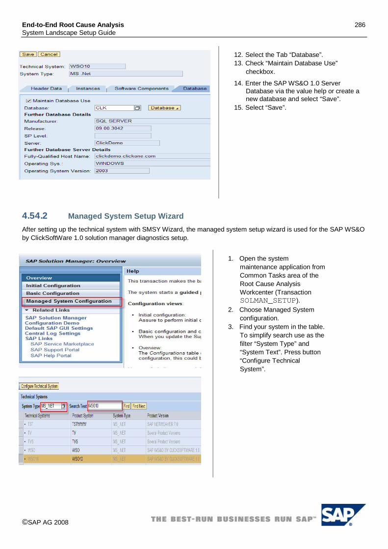
End-to-End Root Cause Analysis 286 System Landscape Setup Guide
©SAP AG 2008
12. Select the Tab “Database”. 13. Check “Maintain Database Use”
checkbox.
14. Enter the SAP WS&O 1.0 Server Database via the value help or create a new database and select “Save”.
15. Select “Save”.
4.54.2 Managed System Setup Wizard After setting up the technical system with SMSY Wizard, the managed system setup wizard is used for the SAP WS&O by ClickSoftWare 1.0 solution manager diagnostics setup.
1. Open the system maintenance application from Common Tasks area of the Root Cause Analysis Workcenter (Transaction SOLMAN_SETUP).
2. Choose Managed System configuration.
3. Find your system in the table. To simplify search use as the filter “System Type” and “System Text”. Press button “Configure Technical System”.

End-to-End Root Cause Analysis 287 System Landscape Setup Guide
©SAP AG 2008
4. By clicking on the button “Continue” go to the “Diagnostic Configuration.
5. Click “Open URL”.
6. Select the Products to be managed by Diagnostics. Uncheck the “Not Diagnostic Relevant”. Press “Set” button.
7. Select the Product Instances to be managed by Diagnostics. Press “Set” button.
8. Click on “Setup <SID> (MS_.NET)” - WS10.
9. Set the installation path (i.e. “C:\Program Files\ClickSoftware\”) and

End-to-End Root Cause Analysis 288 System Landscape Setup Guide
©SAP AG 2008
other required data. Verify Wily data.
10. Press “Next” button to finish this step.
11. Before setup, we should see the screen similar to the one shown on the left.
12. Press “Setup” button. 13. Wait up until Setup will be
finished.

End-to-End Root Cause Analysis 289 System Landscape Setup Guide
©SAP AG 2008
14. After setup, we should see the screen similar to the one shown on the left.
15. Press “Quit” button to finish.
4.55 SAP Alloy SAP Alloy has two main instances, Alloy JAVA ADDON and Alloy DOMINO SERVER. For a typical Alloy landscape, you need to perform diagnostics setup and configuration for both main instances. Alloy JAVA ADDON is installed on SAP J2EE engine, which can register itself against the central SLD via the existing SLD service. After SLD registration is done, you need to manually modify the technical system created automatically via an SLD landscape fetch. Alloy DOMINO SERVER provides an SLD data supplier, which registers an Alloy DOMINO SERVER as a technical system of type ‘Third Party’. Unfortunately, type ‘Third Party’ does not work with Diagnostics of Solution Manager. As a workaround, we need to manually create a technical system for Alloy DOMINO SERVER with type ‘Unspecified’. The current SLD data supplier of Alloy DOMINO SERVER will be improved in the future. After the technical systems for the above main instances are ready, you can run diagnostics setup for the technical systems.

End-to-End Root Cause Analysis 290 System Landscape Setup Guide
©SAP AG 2008
4.55.1 Manual creation of technical system for Alloy JAVA Add-on
1. Log on to your Solution Manager system. 2. Go to transaction ‘SMSY’. 3. Navigate to ‘Landscape Components’
‘Systems’ --> “SAP NETWEAVER’ and select the technical system which is automatically created for the J2EE engine of Alloy.
4. Select tab ‘Header Data’ and switch to the ‘Change’ mode.
5. Click on ‘Change Product Assignment’. 6. In the ‘Installed Product Versions’ list, make
sure column ‘Active’ is selected for both ‘ALLOY 1.0’ and ‘SAP NETWEAVER’.
7. Save the change, close the window and return to tab ‘Header Data’.

End-to-End Root Cause Analysis 291 System Landscape Setup Guide
©SAP AG 2008
8. Navigate to ‘Landscape Components’ ‘Systems’ ‘ALLOY’ and select the newly created technical system, which has the same System ID as the J2EE engine.
9. Select tab ‘Selection of Main Instances’. 10. Make column ‘Relevant’ and then column
‘System Component Assignment’ for ‘SAP Alloy Java’.
11. Use the input help to select the System Component which is automatically created for the J2EE engine via the SLD landscape fetch.
12. Save all the changes.

End-to-End Root Cause Analysis 292 System Landscape Setup Guide
©SAP AG 2008
4.55.2 Manual creation of technical system for Alloy DOMINO SERVER
1. Log on to your Solution Manager system. 2. Go to transaction
‘SOLMAN_WORKCENTER’ and select ‘Root Cause Analysis’ work center.
3. From the ‘Common Tasks’ area on the left hand side, click on ‘System Maintenance’ under ‘Setup and Check’.

End-to-End Root Cause Analysis 293 System Landscape Setup Guide
©SAP AG 2008
4. In the browser window, click on ‘Create’ to create a technical system.
5. Switch to tab ‘Header Data’, input an SID in field ‘Technical System’ and select ‘Unspecified’ in field ‘Type.
6. Click on ‘Add Main Instance’ and select product ‘ALLOY 1.0’ Main Instance ‘SAP Alloy Domino Server’.
7. Mark the ‘Production’ checkbox and save the technical system by clicking on ‘Save’.
8. Switch to tab ‘Instance’.
9. If the SLD data supplier is used and it has reported data to the SLD correctly, a server has already been created. Please select the correct server by using the input help. If not, please click on ‘New Server’ to create a new server for the host on which Alloy DOMINO SERVER is installed.
10. In column ‘Instance’, provide the instance name. E.g. ‘<Host Name>_01’.
Switch to tab ‘Software Components’. 11. Make sure ‘SAP IW DOMINO SERVER
150’ is in the Software Component list and then save the technical system.

End-to-End Root Cause Analysis 294 System Landscape Setup Guide
©SAP AG 2008
4.55.3 Diagnostics configuration for Alloy JAVA Add-on
1. In Managed System Configuration -> Diagnostics Configuration, click OPEN URL beside Configure Diagnostics. This opens a new browser window for the specific technical system.
2. Expand the breadcrumb beside the SID and uncheck checkbox ‘Not Diagnostics Relevant’.
3. Select the following product versions and click on ‘Set’.
‘ALLOY 1.0’
‘SAP NETWEAVER 7.0’
4. Click on ‘Setup <SID> (JAVA)’.
5. If associated SMD agent does not have a server name assigned, the following message will be displayed on the next page.
‘The SMD Agent ‘<Host Name>’ has no Server Name associated to! Please, assign it one.’
Select the correct ‘SMD Agent’ and ‘Wily EM Host/port’.
Provide the correct ‘System Install Path’ and

End-to-End Root Cause Analysis 295 System Landscape Setup Guide
©SAP AG 2008
‘Instance Path’. By default, ‘System Install Path’ is ‘<Drive>:\usr\sap\<SID>\’ and ‘Instance Path’ is ‘<Drive>:\usr\sap\<SID>\<Instance>\’.
6. Click on ‘Set’.
Input correct parameter values in section ‘JAVA Connect Parameters’ and ‘Load Balancer or Jump-In Host’ section if applicable.
7. Click on ‘Next’.
8. Follow the rest of the wizard to complete the setup.
9. Make sure every step has a green light after all steps are executed.
4.55.4 Diagnostics configuration for Alloy DOMINO SERVER
1. Log on to the Solution Manager system.
2. Go to transaction “SOLMAN_WORKCENTER” and select ‘Root Cause Analysis’ work center.
3. Click on ‘Diagnostics Setup’ under ‘Setup and Check’ from the navigation area on the left hand side. This opens a new browser window.

End-to-End Root Cause Analysis 296 System Landscape Setup Guide
©SAP AG 2008
4. Click on ‘Managed System’ and then click on ‘Setup Wizard’ from ‘Application Selection’ on the left hand side.
5. From the technical system list, scroll up/down or use the ‘Jump to SID’ function to locate the technical system created above. Select the technical system.
6. Expand the breadcrumb beside the SID and uncheck checkbox ‘Not Diagnostics Relevant’.
Select the following product version and click on “Set”.
“ALLOY 1.0”
Make sure ‘SAP Alloy Domino Server’ is listed in column ‘Main Instance’.
Click on ‘Setup <SID> (UNSPECIFIC)’.
7. If associated SMD agent does not have a server name assigned, the following message will be displayed on the next page.
‘The SMD Agent ‘<Host Name>’ has no Server Name associated to! Please, assign it one.’
Select the correct “SMD Agent” and “Wily EM Host/port”.
Provide the correct ‘System Install Path’. By default, ‘System Install Path’ is ‘<Drive>:\IBM\Lotus\Domino\’.
Click on ‘Set’.
Click on ‘Next’.
Follow the rest of the wizard to complete the setup.
Make sure every step has a green light after all steps are executed.
4.56 ACROBAT CON LEARN BY ADOBE 7.0 For ACROBAT CON LEARN BY ADOBE 7.0 (previous version called SAP eLearning Adobe Connect 6.2), an automated creation of the technical system via the SLD is currently not supported. Therefore you have to create the technical system manually and afterwards connect the managed system using connect managed system wizard.

End-to-End Root Cause Analysis 297 System Landscape Setup Guide
©SAP AG 2008
4.56.1 Manual creation of technical system for SAP elearning Adobe Connect
1. Open the “System Maintenance” application from the common tasks area of the “Root Cause Analysis” Workcenter (Transaction: SOLMAN_WORKCENTER).
2. Select “Create”.
3. Enter a System ID for your ACROBAT CON LEARN BY ADOBE 7.0 Server into field “Technical System”, select type “unspecified” and enter a description.
4. Select “Save”.
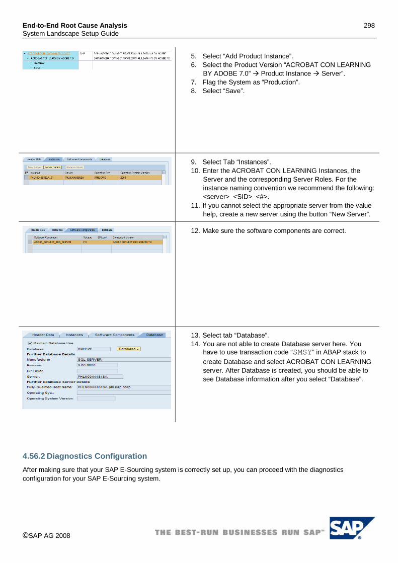
End-to-End Root Cause Analysis 298 System Landscape Setup Guide
©SAP AG 2008
5. Select “Add Product Instance”. 6. Select the Product Version “ACROBAT CON LEARNING
BY ADOBE 7.0” Product Instance Server”. 7. Flag the System as “Production”. 8. Select “Save”.
9. Select Tab “Instances”. 10. Enter the ACROBAT CON LEARNING Instances, the
Server and the corresponding Server Roles. For the instance naming convention we recommend the following: <server>_<SID>_<#>.
11. If you cannot select the appropriate server from the value help, create a new server using the button “New Server”.
12. Make sure the software components are correct.
13. Select tab “Database”. 14. You are not able to create Database server here. You
have to use transaction code “SMSY” in ABAP stack to create Database and select ACROBAT CON LEARNING server. After Database is created, you should be able to see Database information after you select “Database”.
4.56.2 Diagnostics Configuration After making sure that your SAP E-Sourcing system is correctly set up, you can proceed with the diagnostics configuration for your SAP E-Sourcing system.

End-to-End Root Cause Analysis 299 System Landscape Setup Guide
©SAP AG 2008
1. Open the diagnostics setup application from the common tasks area of the “Root Cause Analysis” Workcenter (Transaction: SOLMAN_WORKCENTER).
2. Choose “Managed Systems”. 3. Choose “Setup Wizard”.
4. Jump to the SID of your ACROBAT CON LEARNING.
5. Set the Adobe Connect as “Diagnostics Relevant”. 6. Start the Setup using the “Setup SID (PRODUCT)” button.
7. In the Setup Parameters step, ensure the following settings:
Select your Wily server. Please fill in n the System Install Path:
/breeze/ if your installation path is selected as this, otherwise enter your system installation path.
8. After this is done, continue with the setup.
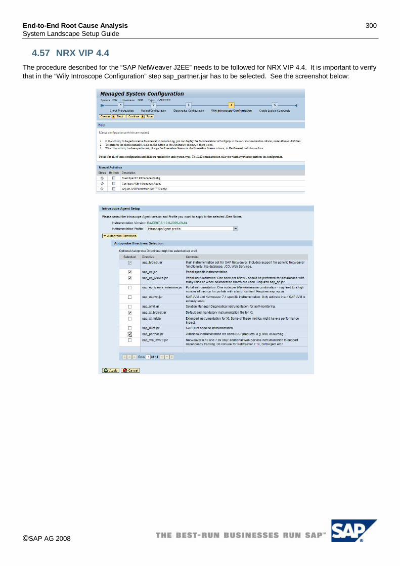
End-to-End Root Cause Analysis 300 System Landscape Setup Guide
©SAP AG 2008
4.57 NRX VIP 4.4 The procedure described for the “SAP NetWeaver J2EE” needs to be followed for NRX VIP 4.4. It is important to verify that in the “Wily Introscope Configuration” step sap_partner.jar has to be selected. See the screenshot below:

End-to-End Root Cause Analysis 301 System Landscape Setup Guide
©SAP AG 2008
4.58 SAP Convergent Charging 2.0 For SAP Convergent Charging (Native Java) the technical system has to be created manually in SAP Solution Manager SMSY. Thereafter, the SMD Managed System Configuration is executed.
4.58.1 Manual creation of technical system for SAP Convergent Charging
1. Call transaction “SMSY”. 2. Repeat the steps 3-8 for all servers which are not yet
maintained in SMSY and which run software components of your SAP Convergent Charging system.
3. Right-click on Server. 4. Select “Create New Server”
5. Enter the server name where your SAP Convergent Charging server is installed.
6. Save your entry.
7. Maintain at least the fields “Fully-Qualified Host Name” and “IP-Address”.
8. Save your entries.

End-to-End Root Cause Analysis 302 System Landscape Setup Guide
©SAP AG 2008
9. Right-click on Database. 10. Select “Create New Database”.
11. Enter the System ID of your SAP Convergent Charging system as Database name.
12. Save your entry.
Please note: SAP Convergent Charging systems are not installed with a System ID, however, in order to identify the system in SAP Solution Manager Diagnostics you need to enter a System ID here. In case of SAP Convergent Charging 2.0, please use the value as reported to the System Landscape Directory by the SAP Convergent Charging SLD Data Supplier.
13. Select your database in field Manufacturer. 14. Select the server on which the database is installed. 15. Save your entries.
16. Right-click on Technical Systems (formally known as System Components).
17. Select “Create New Technical System” (formally known as New System Component”).
18. Enter the System ID of your SAP Convergent Charging system as System Component name.
19. Select type “Unspecified”. 20. Leave the field Installation Number empty. 21. Save your entries.

End-to-End Root Cause Analysis 303 System Landscape Setup Guide
©SAP AG 2008
22. Select tab “Header Data” 23. Set flag “Production” 24. Select the Database you maintained previously 25. Save your entries.
26. Select tab “Instances” 27. Repeat the following for each server (host) where SAP
Convergent Charging is installed 28. Add a new line. 29. Select the Server in field “Server”. 30. Maintain the Instance Name according to the following
naming convention: <Server Name>_<System ID> 31. Save your entries.
32. Select tab “Software Components”
33. Select button: “Copy Software Component from Main Instance”
34. Select Product “SAP Convergent Charging”. 35. Select the correct Product Version. 36. Select Main Instance “CC Core Server”. 37. Select “Continue (Enter)” 38. Repeat these steps for the Main Instances “CC BART
Server” and “CC IEC” 39. Save your entries.

End-to-End Root Cause Analysis 304 System Landscape Setup Guide
©SAP AG 2008
40. Right-click on Product Systems (formally known as Systems).
41. Select “Create New Product System”.
42. Enter the System ID of your SAP Convergent Charging system.
43. Select product “SAP Convergent Charging”. 44. Select the correct Product Version. 45. Leave the field Installation Number empty. 46. Save your entries.

End-to-End Root Cause Analysis 305 System Landscape Setup Guide
©SAP AG 2008
47. Select tab “Product Instance Selection (formally known as “Selection of Main Instances”).
48. Select flags “Relevant” and “System Component” for the Main Instances
CC BART Server CC Core Server CC IEC
49. Assign the Technical System (System Component) defined above and select the Type “Unspecified”.
50. Save your entries.
51. Select tab “Header Data” 52. Set flag “Production” and maintain Description according
to your naming convention. 53. Save your entries.
4.58.2 Installation of SAP Solution Manager Diagnostics Agent and SAP Host Agent If not already done so, SAP Host Agent and SAP Solution Manager Diagnostics Agent needs to be installed on all servers (hosts) where SAP Convergent Charging components are installed. The SAP Convergent Charging 2.0 Installer performs these installations already. For AP Convergent Charging 1.0, please refer to SAP Note 1234387.
4.58.3 SAP Solution Manager Diagnostics Configuration After setting up the technical system, the diagnostics configuration needs to be performed.
1. Open the Managed System Configuration wizard for SAP Solution Manager (Transaction: SOLMAN_SETUP).
2. Select “Managed System Configuration”. 3. Type into field System Type “UNSPECIFIC” and confirm. 4. Select the SAP Convergent Charging system from the list
of technical systems. 5. Select “Configure Technical System”.

End-to-End Root Cause Analysis 306 System Landscape Setup Guide
©SAP AG 2008
6. Select Diagnostics Configuration. 7. Select “Open URL” on Configure Diagnostics.
8. If the product version is set to “Not Diagnostic Relevant” un-select the checkbox.
9. Select Managed Products. 10. Select “Set”. 11. Select .Product Instances and select the three previously
assigned instances. 12. Select “Set” 13. Select “Setup SCC (Unspecific)”

End-to-End Root Cause Analysis 307 System Landscape Setup Guide
©SAP AG 2008
14. For each instance, enter the system installation path (e.g. D:\SAP_CC_1_0\) and select set.
15. For the software components enter the paths to according to the example given on the left-hand side.
16. Save your entries and continue the setup (“Next”).
17. Leave the default execution steps and select “Setup”
18. Verify the setup and leave the setup wizard with the “Quit” button.

End-to-End Root Cause Analysis 308 System Landscape Setup Guide
©SAP AG 2008
4.59 SAP EIO by SmartOps 6.3 (Enterprise Inventory Optimization) The SLD Data Supplier is configured to stream its system landscape information to the central SLD. As EIO by SmartOps 6.3 is hosted on the SAP J2EE Engine, the SLD Data Supplier service of the SAP J2EE Engine needs to be configured to report the appropriate data to the central SLD. Please refer to the following information to publish system landscape information to the SLD.
SAP Note: 1147499 – Connection to the System Landscape Directory SAP Note: 673144 – J2EE Engine Registration in the System Landscape Directory SAP Help:
http://help.sap.com/saphelp_nw70/helpdata/EN/42/e33ae230ba3ee2e10000000a1553f6/frameset.htm
4.59.1 Configuring Technical System for SAP EIO by SmartOps 6.3
26. Open the System Landscape application (Transaction: SMSY)
27. Go to Landscape components Server 28. Check if the <server name> exists. If so, verify server
details.
29. Go to Header Tab to verify if the Data Supplier is “SLD”.

End-to-End Root Cause Analysis 309 System Landscape Setup Guide
©SAP AG 2008
30. Go to Landscape components Database 31. Check if the <SAP Netweaver WebAS Java SID>
exists. If so, verify Database 32. Go to Header Tab to verify if the Data Supplier is
“SLD”.
33. Go to Landscape components Product Systems SAP Netweaver CE and choose your system (SID that is created as part of the SLD data).
34. Ensure Java Application Server is checked as relevant. 35. Ensure Technical system is input based on System
type Java.

End-to-End Root Cause Analysis 310 System Landscape Setup Guide
©SAP AG 2008
36. On the Header data, ensure Product version is selected as SAP “EIO BY SMARTOPS 6.3”
37. Go to Landscape components Product Systems SAP Netweaver CE and choose your system (SID that is created as part of the SLD data).
38. Check if the <SAP Netweaver WebAS Java SID> exists. If so, verify the instances. It should show one SCS Instance, one or more dispatcher and instance nodes.
39. Go to Header Tab to verify if the Data Supplier is “SLD”.
40. Go to Software Components verify Software Component “SO_MIPO” is listed. If it is not found then edit, using Display <> Change option Click on of Prod.Instance button and choose the Product release specific software components and Save.

End-to-End Root Cause Analysis 311 System Landscape Setup Guide
©SAP AG 2008
4.59.2 Diagnostics Configuration After setting up the technical system, the diagnostics configuration needs to be performed.
18. Open the configuration wizard for SAP Solution Manager (Transaction: SOLMAN_SETUP)
19. Select Managed System Configuration 20. Select system type JAVA 21. Select the SID of SAP Netweaver CE JAVA (Example:
LCE) 22. Select Configure System
23. Perform the described steps for the managed system (detailed description available in the linked IMG documentation)
24. Set the status of the activity to performed 25. Start the diagnostics wizard using the link Configure
Diagnostics.
26. Your system is pre-selected. 27. To mark the system as diagnostics relevant open the tray.
You will initially see “NOT DIAGNOSTIC RELEVANT” or other product might be shown here.
28. Ensure SAP EIO by SmartOps 6.3 & SAP Netweaver CE 7.1 is selected.
29. Set and continue.

End-to-End Root Cause Analysis 312 System Landscape Setup Guide
©SAP AG 2008
30. For each instance you need to enter the EIO system installation path & Software Component Path: (e.g. Component: SO_MIPO 6.3, Path: D:\MIPO_netweaver\) and select set.
31. After entering the needed information, hit “Set” button and continue using “Next” the setup.
32. In the last step, status of green indicators will show up as successful completion. Yellow indicator may signal some warnings exist.
4.60 SAP Invoice Management (VIM Approval Portal) by Open Text 5.2
4.60.1 SLD Data Supplier Configuration The SLD Data Supplier is configured to stream its system landscape information to the central SLD. As SAP Invoice Management (VIM Approval Portal) is hosted on the SAP J2EE Engine, the SLD data supplier must be configured to report the appropriate data to central SLD.
SAP Note: 1147499 – Connection to the System Landscape Directory SAP Note: 673144 – J2EE Engine Registration in the System Landscape Directory SAP Service Marketplace: http://service.sap.com/sld
Media Library SLD User Manual SAP NetWeaver 7.0 SPS06 SAP Help Portal: http://help.sap.com
Documentation SAP NetWeaver SAP NetWeaver 7.0 SAP Library SAP NetWeaver SAP NetWeaver Library SAP NetWeaver by Key Capability Solution Life Cycle Management by Key Capability
Software Life Cycle Management System Landscape Directory

End-to-End Root Cause Analysis 313 System Landscape Setup Guide
©SAP AG 2008
4.60.2 Solution Landscape Definition After the SLD Data has been transferred over successfully, we define the solution landscape definition in SMSY for SAP Invoice Management (VIM Approval Portal).
1. Log on to the Solution Manager system. 2. For further assistance, refer to SAP Note 987835. 3. Enter transaction SMSY in Solution Manager. The following components of the system landscape definition will be automatically created because of the SLD data supplier from the managed system:
Server Database System Components
Check if the server is created properly as shown. (i.e. Landscape Components Server usphlvm1022)
4. Check if the database is created properly as shown to the left (i.e. Landscape Components Databases LTP).
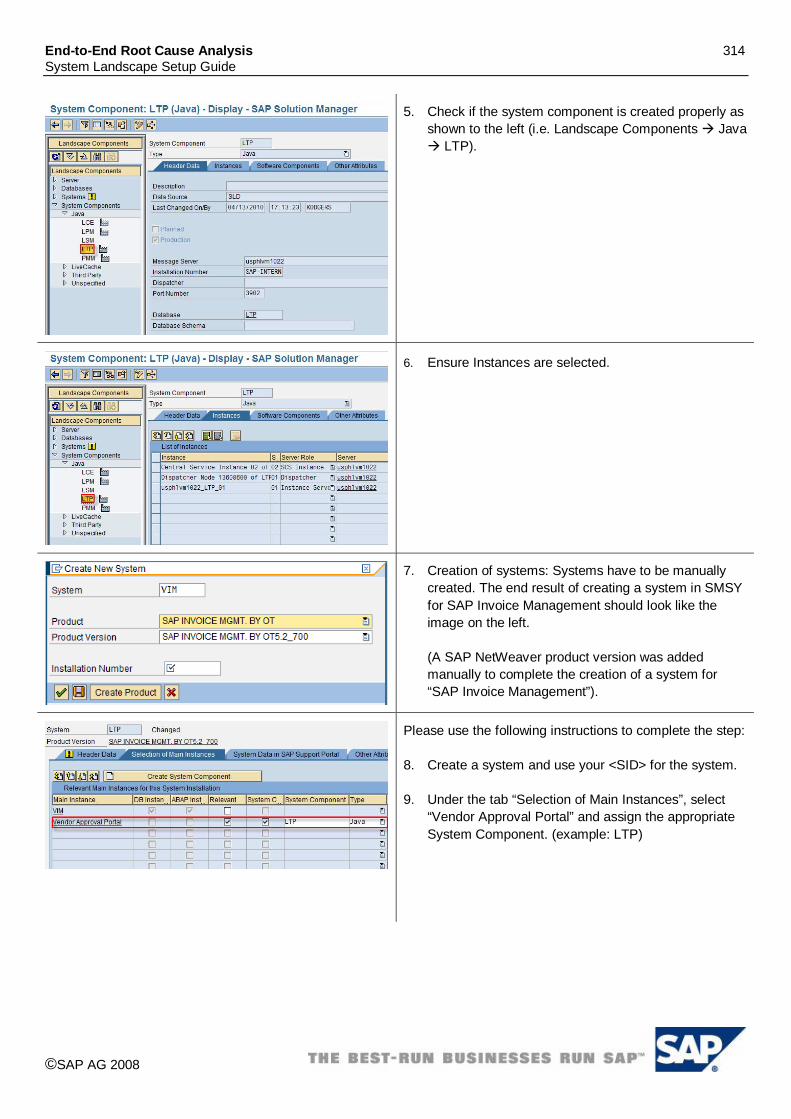
End-to-End Root Cause Analysis 314 System Landscape Setup Guide
©SAP AG 2008
5. Check if the system component is created properly as shown to the left (i.e. Landscape Components Java
LTP).
6. Ensure Instances are selected.
7. Creation of systems: Systems have to be manually created. The end result of creating a system in SMSY for SAP Invoice Management should look like the image on the left. (A SAP NetWeaver product version was added manually to complete the creation of a system for “SAP Invoice Management”).
Please use the following instructions to complete the step: 8. Create a system and use your <SID> for the system.
9. Under the tab “Selection of Main Instances”, select
“Vendor Approval Portal” and assign the appropriate System Component. (example: LTP)

End-to-End Root Cause Analysis 315 System Landscape Setup Guide
©SAP AG 2008
10. Change over to “change mode” . Under the tab “Header Data”, click “Installed Product Version”. A new window should open as shown in the figure below. Check “Free Product/Select Product Version”, select the product and the product version as shown to the left.
11. Use the “Copy” button to copy the product in the list below. Save the selection and one should see a new product added.
12. Because of adding SAP NetWeaver to the list of product versions above, another system is automatically added under the name “SAP NetWeaver”. Please scroll down to check under “Systems” “SAP NetWeaver” <SID>. By default, SAP NetWeaver system assumes that the component beneath is “Application Server ABAP”. As SAP Invoice Management is a Java based product, we need to change the component to “Application Server Java”. This is achieved by de-selecting the “Relevant” checkbox for “Application Server ABAP” and selecting the same checkbox for “Application Server Java”. See the figure to the left.
4.60.3 Managed System Setup Wizard The managed system setup wizard is used after the SAP Invoice Management solution landscape has been designed in SMSY. This is the final step toward completing the Solution Manager Diagnostics setup.
1. Using Solution Manager Diagnostics go to Diagnostics Setup Managed Systems Setup Wizard, enter the SID in the “Jump to SID” field and hit “Enter”.

End-to-End Root Cause Analysis 316 System Landscape Setup Guide
©SAP AG 2008
2. As the product versions SAP Invoice Management 5.2 and SAP NetWeaver 7.0 both were added in the previous step, we should be able to see the same in the wizard. Use the CTRL key to select both product versions and click on “Set”.
3. The result should like the image on the left.
4. Click next to add the details in the next screen as shown to the left.
Remember to set the install path, i.e. d:/OpenText/ and expand and enter the correct optional component path for all the components.

End-to-End Root Cause Analysis 317 System Landscape Setup Guide
©SAP AG 2008
5. Before setup, we should see a screen similar to the one shown to the left.
6. After setup, the results are as shown to the left.
4.60.4 CA Wily Introscope Configuration After setting up the SAP Invoice Management (VIM Approval Portal) system using the managed system wizard, the managed system needs to be configured with the CA Wily Introscope Java Agent. To switch on reporting of SAP Invoice Management server-specific Wily Introscope metrics:
Install Wily Introscope Java Agent as per the Setup guide for Introscope: http://service.sap.com/instguides Installation & Upgrade Guides SAP Components SAP Solution Manager Release 7.0 EHP 1 Installation Wily Introscope Setup Guide 8.0
Additionally, you may reference SAP Note 797147. Restart the J2EE instance.
For general information about the installation, configuration and use of CA Wily Introscope, visit the SAP Service Marketplace at the following locations:
https://service.sap.com/diagnostics Installation and Configuration Wily Introscope 8.x Installation Guide https://service.sap.com/diagnostics Media Library Wily Introscope Workstation User Guide 8.x Wily &
Introscope WebView User Guide 8.x

End-to-End Root Cause Analysis 318 System Landscape Setup Guide
©SAP AG 2008
4.61 SAP Invoice Capture Center by Open Text 5.2
4.61.1 SLD Data Supplier Configuration The SLD Data Supplier is configured to stream its system landscape information to the central SLD. As SAP Invoice Capture Center by Open Text 5.2 is hosted on the MS .NET server, the SLD Data Supplier must be configured to report the appropriate data to the central SLD. SAP ICC 5.2 SP2 and later versions include an SLD Data Supplier Configuration tool. This application can be found in the root installation directory for ICC. (Ex: D:\Open Text\Invoice Capture Center 5.2\InvoiceCaptureCenterSLDDataSupplierConfiguration.exe)
1. Enter the required information to connect to the SLD.
2. Click “Test collect and send data”. 3. A pop up should appear indicating the test
connection succeeded. Click “OK”. 4. Click “OK”. The application will exit.
The technical system should be picked up in SMSY when the landscape fetch job is run on Solution Manager. Please ensure that this fetch job is running periodically, or schedule an immediate job after using the configuration tool.
5. Open the Solution Manager SMSY transaction (Solution Landscape).
6. Check that a system component “INVOICE” has been created as type “Third Party” and verify the header data is correct.
4.61.2 Solution Landscape Definition After the SLD Data has been transferred over successfully, we define the solution landscape definition in SMSY for SAP Invoice Capture Center.

End-to-End Root Cause Analysis 319 System Landscape Setup Guide
©SAP AG 2008
1. Open the Solution Manager SMSY transaction again.
2. Right click on “Systems” and select “Create New System”.
3. Name the system (Ex: “INVOICE”). 4. Select the product. 5. Select the appropriate product version.
6. The new system now appears in the list. 7. Select the system, navigate to the Header Data
tab if necessary, and click “Installed Product Versions”.
8. First, select the checkbox. 9. Locate the product MS IIS and version MS IIS
6.0 and select “Copy”. 10. Repeat for MSFT.NET and SAP ICC (see left). 11. Check the box to designate SAP INVOICE
CAPT.CENT.BY OT5.2 as “Leading Product Version”.

End-to-End Root Cause Analysis 320 System Landscape Setup Guide
©SAP AG 2008
12. On the left navigation bar, select MS .Net, and right click, then “Create New System Component”.
13. Create a new system component for “INVOICE” (or your system name) with type MS .Net.
14. Click “Save” and “Okay (check)”.
15. Select the System Component you just created. 16. Navigate to the Instances tab and add your
physical server and instance name following the recommended convention: <hostname>_<sid/shortsystemname>_<#>
17. Click the Software Components tab, click Copy from Main Instance, and locate and enter each of the Software Components and Component Versions listed (MS.NET components and ICC components).
18. Click “Okay”.
19. Click on the INVOICE system under the “Systems” node on the left.
20. Select tab “Selection of Main Instances”. 21. Select each of the Main Instance rows and
check the “Relevant” and “System Component Assignment” checkboxes.
22. Indicate the System Component “INVOICE” of type “MS .Net” for each row.
23. Save.

End-to-End Root Cause Analysis 321 System Landscape Setup Guide
©SAP AG 2008
4.61.3 Diagnostics Configuration After the solution landscape has been set up, the diagnostics configuration needs to be performed.
1. Open the configuration wizard for SAP Solution Manager (Transaction: SOLMAN_SETUP).
2. Select “Managed System Configuration”. 3. Select system type “MS_.NET”. 4. Select the previously created SAP Invoice
Capture Center 5.2 technical system “INVOICE”.
5. Select “Configure System”.
6. Perform the described steps for the managed system (detailed description available in the linked IMG documentation).
7. Set the status of the activity to “Performed”. 8. Start the diagnostics wizard by clicking
“Configure Diagnostics” (if it is a link) otherwise click the [Open URL] button.
9. Your system is pre-selected. 10. To mark the system as diagnostics-relevant
open the tray.

End-to-End Root Cause Analysis 322 System Landscape Setup Guide
©SAP AG 2008
11. Unselect the checkbox. 12. Select MS IIS 6.0, MSFT .NET 3.0 and SAP
INVOICE CAPT.CENT. BY OT5.2 Product Versions. (Hold down Ctrl while clicking to select multiple line items)
13. Select “Set”. 14. Select “Setup” to continue the setup.
15. For each instance you need to enter the system installation path (e.g. D:\Program Files\OpenText\Invoice Capture Center 5.2\) and select “Set”.
16. After entering the needed information, click Set.
17. Click the checkbox to select the instance. 18. Click “Next”.
19. Continue the setup and review that the results were successful.
4.61.4 CA Wily Introscope Configuration After setting up the SAP Invoice Capture Center system using the managed system wizard, the managed system needs to be configured with Wily Introscope .NET Agent. Please follow the below mentioned guidelines: To switch on reporting of SAP Invoice Capture Center server-specific Wily Introscope metrics:
Install Wily Introscope .NET Agent as per the SAP Note 1126554. Restart the IIS Server.

End-to-End Root Cause Analysis 323 System Landscape Setup Guide
©SAP AG 2008
For general information about the installation, configuration and use of CA Wily Introscope, visit the SAP Service Marketplace at the following locations:
https://service.sap.com/diagnostics Installation and Configuration Wily Introscope 8.x Installation Guide https://service.sap.com/diagnostics Media Library Wily Introscope Workstation User Guide 8.x Wily &
Introscope WebView User Guide 8.x
4.62 SAP RTOM 7.0 (Real Time Offer Management) For SAP RTOM an automated creation of the technical system via the SLD is currently not supported. Therefore you have to create the technical system manually and afterwards perform the managed system configuration using the Diagnostics setup wizard.
4.62.1 Configuration on managed system Managed system needs to be configured with Wily Introscope .NET Agent as well as the Diagnostics Agent.
To switch on reporting of SAP specific Wily Introscope metrics: o Install Wily Introscope .NET Agent as per the SAP Note 1126554
Download and Install the Diagnostics Agent from Service Marketplace
4.62.2 Manual creation of technical system for SAP RTOM
1. Go to the system landscape transaction (/nSMSY) in Solution Manager.
2. Create New Server (host where RTOM is installed) 3. Similarly highlight and right click to create Database as
necessary.

End-to-End Root Cause Analysis 324 System Landscape Setup Guide
©SAP AG 2008
4. Create a new system component by right click on “Technical Systems” (also, formally known as “System Components”) in the landscape components section. Select a unique system ID and type “Unspecified”.
5. Go to Header Data Tab of the Technical System that was created for RTOM: (Example: RTM SID under Unspecified category) and input the information. Refer to the screenshot on the left as an example.
6. Go to Instances Tab. 7. Enter the Instance information. Format is
<Servername>_<SID>.

End-to-End Root Cause Analysis 325 System Landscape Setup Guide
©SAP AG 2008
8. Go to Software Components tab. 9. In the Edit mode (Display <> Change). 10. Choose “of Prod.Instance” command button. 11. Choose Product: “SAP RTOM” 12. Product Version: “SAP RTOM 7.0” 13. Prod. Instance: “RTD Engine Server” 14. Enter and save the information.
15. Go to Product Systems under Landscape Components (formally known as “Systems”).
16. Right click on Product Systems and choose “Create New Product System”.
17. Input Unique Product System.( Example RTM). 18. Choose Product: “SAP RTOM”. 19. Choose Product Version: “SAP RTOM 7.0”

End-to-End Root Cause Analysis 326 System Landscape Setup Guide
©SAP AG 2008
20. Under Product Systems (formally known as “Systems”), navigate to the unique SID that is created for RTOM. (Example: RTM)
21. Go to the Header Data Tab. 22. Ensure the Active Product Version appears as shown in the
screen on the left. (Example: SAP RTOM 7.0) 23. Save the selection.
24. Go to the Product Instance Selection Tab. 25. Ensure Prod. Instance RTD Engine Server has been
selected as “Relevant”. 26. Technical System: (Example: “RTM” is selected and
corresponding System Type is set to “Unspecified”).
4.62.3 Diagnostics Configuration After setting up the technical system, the diagnostics configuration needs to be performed.
1. Open the Managed System Configuration wizard for SAP Solution Manager (Transaction: SOLMAN_SETUP)
2. Select Managed System Configuration 3. Select system type Unspecific 4. Select the relevant RTOM system. 5. Select Configure System

End-to-End Root Cause Analysis 327 System Landscape Setup Guide
©SAP AG 2008
6. Perform the described steps for the managed system of RTOM.
7. Set the status of the activity to performed 8. Start the diagnostics wizard using the link Configure
Diagnostics
9. Your system is pre-selected 10. To mark the system as diagnostics relevant open the tray. 11. Select specific to your requirements (version RTOM 7.0 12. Select Set 13. Check in the main instances tray for RTD Engine Server is
selected. 14. Select Set 15. Select Setup to continue the “Setup <SID>(system type)”.
16. For each instance you need to enter the RTOM system installation path: Ensure to enter the RTOM system installation path relevant to your installation.
Example: RTOM 7.0 C:\Program Files\SAP CRM\RTOM\ Furthermore insert the component install path after expanding the Software components paths tray. Make sure that there are paths included for: RTD ENGINE 7.0 (Default: C:\Program Files\SAP CRM\RTOM\)
17. Select “Set” after the right Wily EM has been chosen. 18. After entering the needed information, save the data and
continue the setup

End-to-End Root Cause Analysis 328 System Landscape Setup Guide
©SAP AG 2008
19. In the last step, status of green indicates as successful setup completion.
4.63 VERTEX O SERIES 4.0, 5.0 For VERTEX SIC 4.0, 5.0 an automated creation of the technical system via the SLD is currently not supported. Therefore you have to create the technical system manually and afterwards perform the managed system configuration using the Diagnostics setup wizard.
4.63.1 Configuration of Diagnostics & Introscope Agent Download and Install the Diagnostics Agent from Service Marketplace SAP Note: 1147499 – Connection to the System Landscape Directory SAP Note: 673144 – J2EE Engine Registration in the System Landscape Directory
4.63.2 Manual creation of technical system for VERTEX O SERIES
1. Go to the system landscape transaction (/nSMSY) in Solution Manager.
2. Create New Server (host where VERTEX O SERIES 4.0 Or 5.0 is installed)
3. Similarly, highlight and right click to create Database.
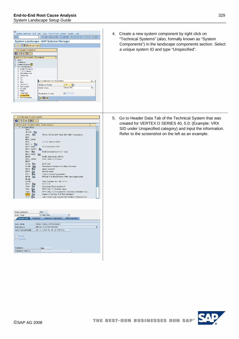
End-to-End Root Cause Analysis 329 System Landscape Setup Guide
©SAP AG 2008
4. Create a new system component by right click on “Technical Systems” (also, formally known as “System Components”) in the landscape components section. Select a unique system ID and type “Unspecified”.
5. Go to Header Data Tab of the Technical System that was created for VERTEX O SERIES 40, 5.0: (Example: VRX SID under Unspecified category) and input the information. Refer to the screenshot on the left as an example.

End-to-End Root Cause Analysis 330 System Landscape Setup Guide
©SAP AG 2008
6. Go to Instances Tab. 7. Enter the Instance information. Format is
<Servername>_<SID>.
8. Go to Software Components tab. 9. In the Edit mode (Display <> Change). 10. Choose “of Prod.Instance” command button. 11. Specific to your installation Choose Product:
Example:“VERTEX O SERIES” 12. Product Version: “VERTEX O SERIES 5.0” 13. Prod. Instance: “Vertex O Series”, “Interface” 14. Enter and save the information.

End-to-End Root Cause Analysis 331 System Landscape Setup Guide
©SAP AG 2008
15. Go to Product Systems under Landscape Components (formally known as “Systems”).
16. Right click on Product Systems and choose “Create New Product System”.
17. Input Unique Product System.( Example VRX). 18. Choose Product specific to your installation.
Example: “VERTEX O SERIES”. 19. Choose Product Version specific to your installation.
Example: “VERTEX O SERIES 5.0”
20. Under Product Systems (formally known as “Systems”), navigate to the unique SID that is created for VERTEX. (Example: VRX)
21. Go to the Header Data Tab. 22. Ensure the Active Product Version appears as shown in the
screen on the left. (Example: VERTEX O SERIES 5.0) 23. Save the selection.
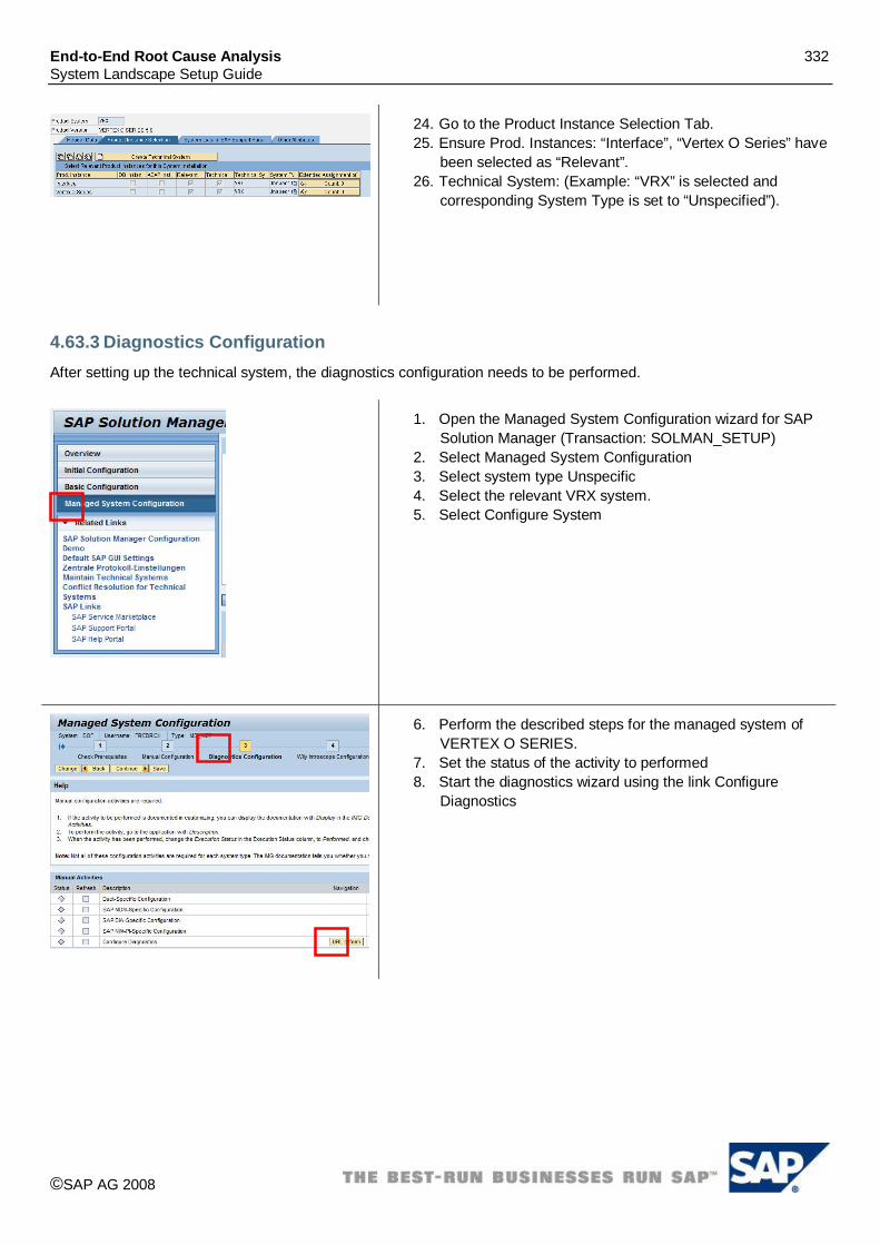
End-to-End Root Cause Analysis 332 System Landscape Setup Guide
©SAP AG 2008
24. Go to the Product Instance Selection Tab. 25. Ensure Prod. Instances: “Interface”, “Vertex O Series” have
been selected as “Relevant”. 26. Technical System: (Example: “VRX” is selected and
corresponding System Type is set to “Unspecified”).
4.63.3 Diagnostics Configuration After setting up the technical system, the diagnostics configuration needs to be performed.
1. Open the Managed System Configuration wizard for SAP Solution Manager (Transaction: SOLMAN_SETUP)
2. Select Managed System Configuration 3. Select system type Unspecific 4. Select the relevant VRX system. 5. Select Configure System
6. Perform the described steps for the managed system of VERTEX O SERIES.
7. Set the status of the activity to performed 8. Start the diagnostics wizard using the link Configure
Diagnostics

End-to-End Root Cause Analysis 333 System Landscape Setup Guide
©SAP AG 2008
9. Your system is pre-selected 10. To mark the system as diagnostics relevant open the tray. 11. Select specific to your requirements version.
Example: VERTEX O SERIES 5.0” 12. Select Set 13. Check in the main instances tray for “Interface”, “Vertex O
Series” is selected. 14. Select Set 15. Select Setup to continue the “Setup <SID>(system type)”.

End-to-End Root Cause Analysis 334 System Landscape Setup Guide
©SAP AG 2008
16. For each instance you need to enter the VERTEX O SERIES system installation path: Ensure to enter the VERTEX system installation path relevant to your installation.
Example: For VERTEX O SERIES 5.0 D:\Vertex\Oseries50\ Furthermore insert the component install path after expanding the Software components paths tray. Make sure that there are paths included for: VERTEX CENTRAL 5.0: (Default: D:\vertex\oseries50\) VERTEX_SIC 5.0: (Default: D:\Vertex\SIC) VERTEX WEB SERVICES 5.0 (Default: D:\vertex\oseries50\) Example for VERTEX O SERIES 4.0 VERTEX CENTRAL 4.0 \vertex\oseries\ VERTEX_SIC 4.0 \vertex\oseries\SIC_HOME VERTEX WEB SERVICES 4.0" \vertex\oseries\
17. Select “Set” after the right Wily EM has been chosen. 18. After entering the needed information, save the data and
continue the setup
19. In the last step, status of green indicates as successful setup completion.


