Enclosure A L-16-276 Emergency Plan Revision 48
224
Enclosure A L-16-276 Emergency Plan Revision 48
Transcript of Enclosure A L-16-276 Emergency Plan Revision 48

Enclosure A L-16-276
Emergency Plan Revision 48

•
•
•
- --00------- ----------
PERRY OPERATIONS MANUAL
Emergency Plan
EP Page: i Rev.: 48
PNPP
TITLE:· EMERGENCY PLAN FOR PERRY NUCLEAR POWER PLANT DOCKET NOS. 50-440
REVISION: 48
PREPARER: Larry VanDerHorst
APPROVER: Frank Payne
EFFECTIVE DATE: 8-23-16
7-24-16 I Date
8-10-16 I Date
I
. I

Section
1. 0
2.0 2.l 2.2 2.3 2.4 2.5 2.6
3.0 3.l 3.2 3.3.
4.0 4.l 4.2
5.0 5.l 5.2 5.3 5.4
6.0 6.l 6.2 6.3 6.4 6.5 6.6 6.7 6.8
7.0 7.l 7.2 7.3 7.4 7.5 7.6 7.7
EP Page: Rev.:
EMERGENCY PLAN FOR PERRY NUCLEAR POWER PLANT DOCKET NOS. 50-440
Table of Contents
Title
DEFINITIONS
SCOPE AND APPLICABILITY Site Description Population Distribution Emergency Planning zones Purpose and Objectives Summary of Emergency Plan Inter-Relationships Participating Governmental Agencies
SUMMARY OF THE EMERGENCY PLAN Emergency Plan Steps Emergency Organizations Emergency Classifications
EMERGENCY CONDITIONS Emergency Classification System State and County Classification System
ORGANIZATIONAL CONTROL OF EMERGENCIES FirstEnergy Organization Emergency Organization Local Services Support Government Agencies
EMERGENCY MEASURES Activation of Emergency Organizations Assessment Actions Onsite Personnel Accountability Offsite Protective Actions Contamination Control Measures Emergency Personnel Dose Control Thyroid Blocking Onsite Protective Actions
EMERGENCY FACILITIES AND EQUIPMENT Emergency Centers Communications Systems ERO Notifications Prompt Alert Siren System Assessment Facilities First Aid.and Decontamination Facilities Protective Equipment and Supplies
ii 48
Page
l-l
2-l 2-1 2-1 2-1 2-2 2-4. 2-5
3-1 3-l 3-l 3-3
4-1 4-l 4-5
5-l 5-1 5-1 5-18 5-20
6-1 6-1 6-5 6-7 6-8 6-12 6-14 6-15 6-15
7-1 7-1 7-5 7-9 7-10 7-ll 7-23 7-23
•
•
•

•
•
•
Section
8.0 8.1 8.2
8.3 8.4
8.5 8.6 8.7 8.8
9.0 9.1 9.2
·9.3
EP Page: iii Rev.: 48
EMERGENCY PLAN FOR PERRY NUCLEAR POWER PLANT DOCKET NOS. 50-440
Table of Contents (Cont.)
Title
MAINTAINING EMERGENCY PREPAREDNESS Organizational Preparedness Review and Updating of the Emergency Plan
and Implementing Instructions Annual Emergency Preparedness Program Review Maintenance and Inventory of Emergency
Equipment and Supplies Maintenance of Emergency Telephone Numbers Public Education and Information News Media Training Drills and Exercises
RE-ENTRY AND RECOVERY Re-entry Phase· Recovery Phase Recovery Notifications
8-1 8-1 8-5
8-5 8-6
8-6 8-6 8-8 8-8
9-1 9-1 9-2 9-4

APPENDIX A
APPENDIX B
APPENDIX C
APPENDIX D
APPENDIX E
EP Page: Rev.:
EMERGENCY PLAN FOR PERRY NUCLEAR POWER PLANT DOCKET NOS. 50-440
LIST OF APPENDICES
INDEX OF EMERGENCY PLAN IMPLEMENTING AND SUPPORT INSTRUCTIONS
LETTERS OF AGREEMENT
LIST OF EMERGENCY EQUIPMENT AND SUPPLIES
LIST OF SUPPORTING PLANS
iv 48
NUREG-0654/FEMA-REP-1 CROSS REFERENCE TO PERRY PLANT EMERGENCY PLAN INDEX
•
•
•

• Section
3-1
4-1
4-2
4-3
5-1
6-1
6-2
• 8-1
•
EP Page: v Rev.: 48
EMERGENCY PLAN FOR PERRY NUCLEAR POWER PLANT DOCKET NOS. 50-440
LIST OF TABLES
Title
Emergency Classifications and the Degree of Involvement by Participating Groups
Emergency Action Levels (EALs)
EAL Abbreviations/Acronyms
NUMARC/NESP-007 Cross-Reference
Perry Plant Emergency Response Organization Functions and Shift Staff Augmentation Plan
Guideline for Protective Actions Against Ingestion of Contamination
Recommended Protective Actions
Training Provisions for Offsite Emergency Response Personnel
3-4
4-8
4-62
4-64
5-23.
6-16
6-17
8-13

Section
2-1
2-2
4-1
4-1
5-1
5-2
6-1
6-2
6-3
6-4
7-1
7-2
7-3
7-4
7-5
7-6
9-1
EP Page: Rev.:
EMERGENCY PLAN FOR PERRY NUCLEAR POWER PLANT DOCKET NOS. 50-440
LIST OF FIGURES
Title
10 Mile Emergency Planning Zone
50 Mile Emergency Planning Zone
Initiating Condition Index
Fission Product Barrier Matrix
Emergency Response Organization (Interim Phase)
Emergency Response Organization (Final Phase)
Emergency Notification
Offsite Monitoring/Decontamination Center Locations
Protective Action Flow Chart
Drywell Radiation Plot
Relative Location of Emergency Response Facilities
Technical Support Center (TSC) Layout
Operations Support Center (OSC) Layout
Emergency Operations Facility (EOF) Layout
Dedicated Emergency Telephone Communications
Siren Locations for PNPP
Recovery o+ganization
vi 48
2-6
2-7
4-6
4-11
5-27
5-28
6-18
6-19
6-20
6-21
7-24
7-25
7-26
7-27
7-28
7-29
9-5
•
•
•

•
•
•
EP Page: vii Rev.: 48
EMERGENCY PLAN FOR PERRY NUCLEAR POWER PLANT DOCKET NOS. 50-440
SCOPE OF REVISION:
Rev. 48 - 1.
2.
3.
4.
5
6.
7 .
8.
9.
10.
Section 7.1.1 para. 6 - Revised to remove the onsite alternate TSC in the TEC.
Section 7.1.1 para. 8 - Revised paragraph since onsite alternate TSC is eliminated and offsite alternate TSC does not need a filtered ventilation system with an isolable capability. Section 7.1.1 para. 9 - Revised to eliminate the paragraph since the paragraph since onsite alternate TSC is eliminated and offsite alternate TSC does not need a filtered ventilation system. Section 7.2.2.1.a - Revised to eliminate the onsite alternate TSC. Section 7.2.2.1.b - Revised to eliminate the onsite alternate TSC. Section 7. 2. 2 . 2 3ra para. from end of section - Revised to PBX extensions are only available in the Control Room and the TSC. Section 7.2.2.2 Emergency Response (5-Way) section -Revised to eliminate the onsite alternate TSC. Appendix C-A - The onsite alternate TSC was replaced by the Training and Education Center as a storage location for portable radiological monitoring equipment and supplies. Appendix C-A - The onsite alternate TSC was replaced by the Training and Education Center as a storage location for decontamination equipment and supplies. Figure 5-1 - Changed location of the PIRT from the TEC to the EOF.
11. Figure 5-2 - Changed location of the PIRT from the TEC to the EOF.
12. Figure 7-1 - Eliminated onsite alternate TSC. 13. Figure 7-4 - Added the PIRT and alternate TSC to the layout
diagram. 14. Figure 7-5 - Eliminated onsite alternate TSC
communications. 15. Section 5.2.2 para. 7 - Removed first floor of the TEC as a
PIRT location. 16. Section 5.2.2.6 - Removed first floor of the TEC as a PIRT
location. 17. Section 5.2.3 - Eliminated the sentence that required the
transferring duties to the JIC upon notification that a NRC site team has been dispatched to the plant.
18. Section 7.0 para. 2 -Eliminated the sentence requiring the JIC to be activated if PIRT is required and cannot be established on the plant site .

COMMITMENTS:
EP Page: Rev.:
viii 48
The following commitments are addressed by the PNPP Emergency Plan (EP) :
LOOll5 L00454 · L00513 L00537 L02480 L02481 L02482
•
•
•

•
•
•
1 . 0 DEFINITIONS
Listed below are terms used in the Emergency Plan, along with definitions that should be applied to these terms. Footnotes are found at the end of this list.
1 . 1 Adverse Meteorology
The meteorology which results in the conservative accident atmospheric
dilution factor value of ~ 6.7E-4 sec/m3.
1.2 Alert
Events are in process or have occurred which involve an actual or · potential substantial degradation of the level of safety of the plant or a security event that involves probable life threatening risk to site personnel or damage to site equipment because of intentional malicious dedicated efforts of a hostile act. Any releases are expected to be limited to small fractions of the EPA Protective Action Guideline exposure levels.
1. 3 Assessment Actions
Those actions taken during or after an accident to obtain and process information necessary to make decisions to implement specific emergency
measures . ( 1)
1 . 4 Average Meteorology
That meteorology which results in the average atmospheric dilution factor
value of < 6.7E-4 sec/m3 but~ 4.4E-5 sec/m3.
1. 5 Central Alarm Station (CAS)
The continuously manned alarm station where all security alarms annunciate.
1.6 Committed Effective Dose Equivalent (CEDE)
The sum of the products of the weighting factors applicable to each of the body organs or tissues and the committed dose equivalent to.these organs or tissues. CEDE is the internal dose component of TEDE .
1-1 Rev. 48

1. 7 Committed Dose Equivalent (CDE)
The dose equivalent to organs or tissues of reference that will be received from an intake of radioactive material by an individual during the 50 year period following the intake.
NOTE
For. dose assessment purposes, CDE for child thyroid is calculated.
1. 8 Contaminated Area
Any material or area accessible to personnel with a loose surface
contamination greater than or equal to 1000 dpm/100cm2 beta-gamma and/or
20 dpm/100cm2 alpha. (2)
Any material or area accessible to personnel with fixed surface area contamination greater than or equal to 0.1 mrem/hr for uncontrolled release.
1. 9 Control Room
The onsite location from which the reactor and its auxiliary systems are controlled. The location of the Control Room is ·on Elevation 654' of the Control Complex.
1.10 Corrective Actions
Those emergency measures taken to mitigate or terminate an emergency situation at or near the source of the problem in order to prevent an uncontrolled release of radioactive material or to reduce the magnitude
of the release, e.g., shutting down equipment and damage control. (1)
1.11 Deep Dose Equivalent (DDE)
The dose equivalent measured at a tissue depth of 1 cm (1000 mg/cm 2 ).
DDE is the external dose component of TEDE.
1.12 Design Basis Accident (DBA)
Occurrences that are not expected to occur but are postulated because their consequences may result in the release of significant amoun~s of radiation.
1 . 13 Dose Projection
The calculated estimate of a radiation dose to individuals at a given location (usually offsite), determined from the quantity of radioactive material released and the appropriate meteorological transport and
dispersion parameters. (3)
1-2 Rev. 48
•
•
•

•
•
•
1.14 Drill
A supervised instruction period aimed at testing, developing, and
maintaining skills in a particular operation. (1)
1.15 Emergency Action Levels (EALs)
Levels which consist ·of specific sets of plant parameters (i.e., instrument indications, system status, .radiological doses and dose rates) that shall be used for emergency classification. EALs are used specifically to provide for early readiness status of emergency response personnel, organizations, and facilities.
l.16Emergency Operations Center (EOC)
An offsite location utilized by State, County and other government agencies and organizations to perform assessments of radiological conditions and to coordinate offsite activities (access,
evacuation, etc.). (4)
l.17Emergency Operations Facility (EOF)
The Emergency Operations Facility is a specifically designated location for the management of overall emergency response activities, the coordination of radiological assessments, and the control of offsite emergency support activities. The Perry Plant Emergency Operations Facility (EOF) is located at 7751 Auburn Road in Concord Township, Ohio 10.44 miles from the Perry Plant.
1.18 Emergency Planning Zones (EPZ)
Two zones that the EPA recommends be established around all nuclear power stations. One zone with a radius of approximately 10 miles (16090 meters) for airborne_ exposure, and the other with a radius of approximately 50 miles (80450 meters) for contaminated food. In these
zones, predetermined protective action plans are needed. (l,3)
1.19 Exclusion Area
The area surrounding the plant in which the licensee has the authority to determine all activities including the exclusion or removal of persons and property from the area. At the Perry Plant this area is established as the area that falls inside the 2900 foot radii centered on the Unit 1 reactor.
1. 20 Exercise
An exercise is a simulated event or series of events that tests the integrated capability and a major portion of the basic elements existing
within emergency preparedness plans and organizations. (l)
1-3 Rev. 48

1.21 Functional
A system, subsystem, train, component or device, though degraded in equipment condition or configuration, is functional if it is capable of maintaining respective system parameters within acceptable design limits.
1. 22 Gap Release
A fission product release that occurs when fuel cladding experiences initial rupture. This consists mostly of activity that was released to void spaces within the fuel rods during normal reactor operation. Rapid depressurization provides the driving force for fission product
escape. (5 )
1.23General Emergency
Events are in process or have occurred which involve actual or imminent substantial core degradation or melting with potential for loss of containment integrity or security events that result in an actual loss of physical control of the facility. Releases can be reasonably expected to exceed EPA Protective Action Guideline exposure levels offsite for more than the immediate site area.
1. 24 Implementing Instructions
Those detailed procedures which provide guidance to individuals and groups for implementation of the provisions of this plan.
1. 25 Joint Information Center (JIC)
A specifically designated offsite location and point of contact for the dissemination of information to the news media during an emergency by Company, Federal, State and Local officials.
1.26 Loss
Unless defined by specific Emergency Action Le~el (EAL) indications, loss shall be defined as a state of inoperability in which functional and operable status cannot be maintained. A system, subsystem, train, component or device is not lost if its functionality is assured.
l.27Meteorological Information and Dose Assessment System (MIDAS))
The software program designed to provide an automated method for determining the present and/or potential offsite consequences of a significant release to the environment from the Perry Plant during an Emergency Plan event.
1. 28 Off site
Any area outside the Owner-Controlled Area fence surrounding the Perry Plant.
1-4 Rev. 48
•
•
•
•
•
•
1. 29 Off site Assembly
Evacuation of onsite personnel to designated locations offsite for the purpose of performing personnel accountability or further personnel contamination monitoring.
1. 30 Onsite
The area within the Owner-Controlled Area fence surrounding the Perry Plant.
1. 31 Onsi te Assembly
Evacuation of personnel from areas within the plant that would be required for any emergency situation with assembly at designated locations as directed by the Operations Manager.
1. 32 Operable/Operability
A system, subsystem, division, component, or device shall be operable or have operability when it is capable of performing its specified safety function(s) and when all necessary attendant instrumentation, controls, normal or emergency electrical power, cooling and seal water, lubrication, and other auxiliary equipment that are required for the system, subsystem, division, component or device to perform its specified safety function(s) are also capable of performing their related support
function(s). (6)
1. 33 Operations Support Center (OSC)
The onsite location in close proximity to the Control Room and Technical Support Center (TSC) to which plant support personnel and other emergency response team personnel report and await instructions. The Operations Support Center (OSC) is located on the 599' level of the Control Complex.
1. 34 Owner-Controlled Area
Areas owned by the FirstEnergy Corporation which are located within or adjacent to the Site Boundary security fence.
L 35 Personnel Monitoring Equipment
Devices designed to be worn or carried by an individual for the purpose of measuring the radiation dose received (e.g., direct reading dosimeters, thermoluminescent dosimeters etc.).
1. 36 Plume Exposure Pathway
The means by which a radioactive cloud (plume) can expose the population at risk and/or onsite personnel to radiation. The time of potential exposure could range from hours to days. The principal exposure sources
for this pathway are: (1,3)
1. Whole body external exposure to gamma radiation from the radioactive plume and fr.om deposited material; and,
1-5 Rev. 48

2. Inhalation exposure from the passing radioactive plume.
1. 37 PNPP
Abbreviation for the Perry Nuclear Power Plant used throughout this document.
1.38 Population at Risk
Those persons for whom protective actions are being or would be taken. (1, 7)
1. 39 Projected Exposure Time (PET)
The estimated period of time that the population in the area surrounding the Perry Plant may be exposed to radiation as a result of an accidental airborne radioactive release. Projected exposure time starts when the airborne radioactivity release is estimated to cross the exclusion area, and ends when the radiation levels offsite are expected to return to
normal. (4 )
1 . 4 o Protected Area
The area encompassing the Vital Areas, all areas inside the double
perimeter barrier fence and the Primary Access Facility (PAF). (8)
1. 41 Protective Actions
Those emergency measures taken before or after an uncontrolled release of radioactive material has o"ccurred for the purpose of preventing or minimizing radiological exposure to persons who would likely be exposed
if the actions were not taken. (1,7)
1.42 Protective Act.ion Guides (PAGs)
Projected radiological dose to individuals in the general population that warrant protective actions following a release of radioactive material. Protective actions would be warranted provided the reduction in individual dose is not offset by excessive risks to individual safety in taking the protective actions. The protective action guides. (PAGs) do not include the dose that has unavoidably occurred prior to the assessment. (1,3,8)
1. 43 Public Information Response Team (PIRT)
Selected staff of the Emergency Public Information Organization who are responsible for dissemination of information during a Perry Plant emergency. They are assigned emergency response duties during an emergency situation that does not require activation of the Joint Information Center (JIC), during the initial stages of an emergency prior to operation of the JIC, or during the recovery of an emergency after deactivation of JIC.
1-6 Rev. 48
•
•
•

•
•
•
1. 44 Radiologically Controlled Area (RCA)
An area within a Restricted Area that is posted and controlled due to the presence of radiation, contamination, or airborne radioactivity or the presence of radioactive material. Radiologically Controlled Area and Radiological Restricted Area (RRA) are synonymous. Radiologically Controlled Area is the preferred term.
1. 45 Recovery Actions
Those actions taken after an emergency to restore the plant as nearly as
possible to pre-emergency conditions. (l)
1. 46 Reentry Actions
The return to an evacuated area, in either the plant or site, for such actions as search and rescue, first aid, firefighting, manipulation or repair of critical equipment or systems, and to assess conditions in preparation for recovery operations.
1.47 Secondary Alarm Station (SAS)
The continuously manned security station where most initial offsite and Emergency Response Organization (ERO) personnel notifications are conducted, and fire alarms annunciate. The Secondary Alarm Station (SAS) is located in the Unit 1 Control Room .
1.48 Site Boundary
The area within the Owner-Controlled Area which is encompassed by a
security fence surrounding the Perry Plant. (8 )
1.49 Site Area Emergency
Events are in process or have occurred which involve an actual or likely major failures of plant functions needed for protection of the public or security events that result in intentional damage or malicious acts; (1) toward site peri;;onnel Or equipment that could lead to the likely failure of or; (2) prevents effective access to equipment needed for the protection of the public. Any releases are not expected to result in exposure levels which exceed EPA Protective Action Guideline exposure levels beyond the site boundary.
1. 50 System Control Center ( SCC)
The Off-site facility located in Akron, Ohio, which controls and coordinates the generation and transmission within the FirstEnergy Corporation
1. 51 State
The State of Ohio .
1-7 Rev. 48

1. 52 Technical Support Center (TSC)
The onsite location which will serve as the focal point for gathering information on current and projected plant status and for the orderly implementation of emergency procedures in support of reactor command and control functions. The TSC is located on the 603'6" level of the Service Building.
1. 53 Technical Support Guidelines (TSGs)
Provide a method for supporting and optimizing the accident management strategies contained in the generic Emergency Procedure Guidelines/Severe Accident Guidelines (EPGs/SAGs) . The TSGs describe enhancements to technical activities performed by the ERO, and consist of the following four inter-related assessments: control parameter, plant status, system status, and EPG/SAG action.
l.54Total Effective Dose Equivalent (TEDE)
The sum of DDE (external dose) and CEDE (internal dose) . For dose assessment purposes, DDE is considered the whole body dose in accordance with NUMARC "White Paper: Implementation of the New EPA Protective Action Guides in Existing Emergency Programs, April 1993."
1. 55 Unrestricted Area
Any area, to which access is not controlled by FirstEnergy Corporation, for purposes of protection of individuals from exposure to radiation and radioactive materials.
1 . 5 6 Unusual Event
Events are in process or have occurred which indicate a potential degradation of the level of safety of the plant or indicate a security threat to facility protection. No releases of radioactive material requiring offsite response or monitoring are expected unless further. degradation of safety systems occurs.
1-8 Rev. 48
---- -· ---- --· -
•
•
•

•
•
•
FOOTNOTE REFERENCES FOR DEFINITIONS:
1 NUREG-0654/FEMA-REP-l, Criteria for Preparation and Evaluation of Radiological Emergency Response Plans and Preparedness in Support of Nuclear Power Plants, November 1980.
2 Plant Administrative Procedure, PAP-0114, Radiation Prot~ction Program.
3 NUREG-0396 (EPA 520/1-78-016), Planning Basis for the Development of State and Local Government Radiological Emergency Response Plans in Support of Light Water Nuclear Power Plants, NRC/EPA, December 1979.
4 The Ohio Plan for Response to Radiation Emergencies at Commercial Nuclear Plants, State of Ohio.
5 NUREG/CR-2925; SAND 82-2004, In-Plant Considerations for Optional Offsite Response to Reactor Accidents, November 1982.
6 Technical Specifications, Perry Nuclear Power Plant, Unit No. 1 (Docket No. 50-440). Appendix "A" to License No. NPF-58.
7 BWR owners' Group Accident Management Guidelines (AMG) Overview Document.
8 EPA-400-R-92-001, Manual of Protective Action Guides and Protective Actions for Nuclear Incidents .
9 Perry Plant Security Plan.
1-9 Rev. 48

•
•
•
2.0
2.1
SCOPE AND APPLICABILITY
This plan is written for, and the provisions are applicable to, the Perry Plant Unit 1.
Site Description
The Perry Plant, Unit 1, is located on the southeastern shoreline of Lake Erie in Lake County, Ohio, approximately seven miles northeast of Painesville, Ohio. FirstEnergy Nuclear Operating Company is responsible for the operation of the plant.
The Perry Plant, Unit 1 is a (3758 MWt) Boiling Water Reactor (BWR) of the General Electric Company design, supplying steam to a General Electric turbine generator.
The plant site covers approximately 1100 acres located on an ancient lake plain approximately 50 feet above the lake low water datum. Although relatively flat, the site has a very gentle slope toward the lake. A large portion of the site is forested, some 250 acres are devoted to the plant structural complex. A comprehensive description of site characteristics and plant location is contained in Chapter 2.0 of the Updated Safety Analysis Report (USAR) for the Perry Nuclear Power Plant.
The primary source of potable water in the area is Lake Erie. The nearest potable water intake is the Painesville Water Supply, approximately 3.9 miles west-southwest of the site .
2. 2 Population Distribution
The population in the area surrounding Perry Plant is distributed from the northeast around to the west southwest. Preparedness Support Instruction, PSI-0013, provides a breakdown of the total permanent resident population within 10-mile EPZ of the plant, and contains the Evacuation Time Estimates (ETE) for areas around the Perry Plant and discusses population distributions in detail.
2 . 3 Emergency Planning Zones
Emergency planning zones (EPZs) are areas designated for which planning is recommended to assure that prompt and eff.ective actions are taken to protect the public in the event of an accident.
Two primary zones have been established for the purposes of emergency planning around the·Perry Plant. The first is the Plume Exposure Pathway EPZ. This zone, commonly referred to as the "10-mile EPZ," encompasses an area roughly corresponding to the area within a 10-mile radius of the Perry Plant. In defining the 10-mile EPZ for the Perry Plant, the following criteria were applied:
1. The designated area must approximate the recommended 10-mile radius area as specified in Federal regulations .
2-1 Rev. 48

2. The designated area must be readily identifiable and comprehensible to allow for effective public broadcasting of information and guidance during an emergency event requiring area evacuation.
3. The perimeter of the designated evaluation area should not have major irregularities to maintain a credible area boundary.
The 10-mile EPZ around the Perry Plant encompasses land areas in Ashtabula, Geauga and Lake Counties, and a defined "safety" zone extending north into Lake Erie. A total of 17 municipal jurisdictions are situated wholly or partially within the 10-mile radius area. Of primary concern in the 10-mile EPZ is direct exposure to a passing radioactive plume and inhalation of radioactive particulate materials. The protective actions for the 10-mile EPZ are discussed in Section 6.4. A review of the topographic conditions and jurisdictional boundaries in the area surrounding the Perry Plant has led to the definition of the EPZ as depicted in Figure 2-1, and described below.
The eastern EPZ boundary follows the Geneva Township boundary south to Interstate 90, and west on I-90 to Route 534. It follows Route 534 south to the Harpersfield Township boundary and continues west to the Geauga/ Ashtabula County line. At this point it follows the county line south to Route 166, and west on Route 166 to the county line. The EPZ boundary continues west along the county line to the Concord Township western boundary. From there it follows township line northward to the intersection with the Con Rail tracks, cross-country to Mentor Marsh, and then continues west through the marsh to Lake_Erie. The EPZ extends into Lake Erie due north from the south shore at the 81° 20' West longitude; then easterly along the 41° 57' North latitude; and finally extends due south along the 80° 56' W longitude to the shoreline.
The second EPZ extends to a 50-mile radius of the Perry Plant. This zone, also known as the Ingestion Pathway EPZ, is shown in Figure 2-2. Once exceeding the 10-mile radius, direct exposure to a passing plume is no longer of significant concern. At this point, the ingestion pathway of exposure is of greatest concern. The State of Ohio has assumed primary responsibility for planning, coordination and implementation of protective actions for the general public within the Ingestion Pathway EPZ. The primary emphasis in the Ingestion Pathway EPZ is on the prevention of uptake by people and animals. Protective Actions for the Ingestion Pathway EPZ are discussed in Section 6.4.4 and in the State of Ohio Nuclear Power Plant Emergency Response Plan.
2.4 Purpose and Objectives
2.4.1 Regulatory Requirements
Section 50.34 to Title 10 of the Code of Federal Regulations (10CFR50.34) "Technical Information, Licensing of Production and Utilization Facilities," requires that a Licensee's Updated Safety Analysis Report (USAR) include specific plans for coping with emergencies which shall include the items specified in Appendix E to Part 50.
2-2 Rev. 48
•
•
•

• 2.4.2
2.4.3
•
•
Supplemental guidance has been provided by the Nuclear Regulatory Commission (NRC) and the Federal Emergency Management Agency (FEMA) in NUREG-0654/FEMA-REP-l.
These documents describe methods acceptable for compliance with regulations regarding nuclear power plant emergency plans.
Purpose of Emergency Preparedness
The purpose of emergency preparedness is to provide a mechanism that would be utilized in making decisions in the event of an emergency, and to assure that the necessary equipment, supplies, and essential services are available.
Objectives of the Emergency Plan
The objectives of the Emergency Plan are as follows:
1. Outline an effective course of action to safeguard the public and plant personnel in the event of an emergency.
2. To establish an emergency organization and assign responsibilities in order to direct the response to an emergency condition or radiological incident and to limit the consequences of the incident.
3 . Terminate or mitigate the radiological consequences of an emergency, both onsite and offsite.
4. Control onsite and offsite surveillance activities to include notifications and coordination of offsite supporting organizations as required.
5. To establish procedures to identify and classify the emergency condition.
6. Evaluate the necessity for public protective actions and implement any protective actions deemed appropriate to protect members of the general public and the plant staff.
7. Provide for the training of all emergency plan personnel.
8. To describe emergency facilities and communication systems available and their utilization by emergency personnel and organizations.
9. Describe an organization to direct and perform recovery and reentry operations .
2-3 Rev. 48

2.5 Summary of Emergency Plan Inter-Relationships
This Emergency Plan should not, by itself, be considered the primary working document to be used during an emergency. The purpose of the Emergency Plan is to classify emergencies according.to their nature and severity, assign responsibilities for actions, and clearly outline an effective course of action to safeguard the public and plant personnel in the event of an emergency.
Inter-relationships of this plan with procedures, other plans, and emergency arrangements are summarized as follows:
2.5.1
2.5.2
2.5.3
2.5.4
Detailed actions to be. taken by individuals in response to onsite emergency conditions at the time of an event are directed by the Emergency Plan Implementing Instructions (EPis) . These instructions provide the detailed mechanisms for response as outlined in this plan. EPis do not cover program administration or normal activities already covered by other plant procedures. As such, EPis will only incorporate certain aspects of the plant's operating procedures, radiological control procedures, and security procedures, where clarification of the instructions is required.
The listing of EPis, contained in Appendix A, shall be considered implementing procedures in accordance with 10 CFR 50, Appendix E.V. Any changes to these instructions shall be submitted to the NRC within 30 days of implementation.
The Security Plan and procedures have been coordinated with this plan to ensure that appropriate emergency actions can be taken. For example, the Security Plan and procedures contain provisions for emergency response personnel and vehicle access when required by the EPis.
The Plant Administrative Procedures (PAPs) and Nuclear Operation Procedures (NOP) define administrative controls such as radiological control limits and precautions, use of personnel monitoring devices, use of protective clothing and equipment, and personnel decontamination. Chemistry instructions govern counting of samples in lab. In addition, Health Physics Instructions provide guidance for performing surveys, analyzing samples, operating/radiation protection equipment, etc. The relevant information and details provided in these documents have either been incorporated in the plan and/or implementing procedures, or have been appropriately referenced.
The Emergency Public Information Organization Instructions Manual (EPIOIM) and this plan are coordinated to ensure that a mechanism is in place to provide accurate and timely information to the public via the news media. The EPIOIM provides a means for exchanging information between each participating agency's spok~sperson and for rumor control during emergencies.
2-4 Rev. 48
•
•
•

•
•
•
2.5.5
2.5.6
2.5.7
The Preparedness Support Instructions (PSis) provide administrative guidance on: (1) the conduct of emergency preparedness drills and exercises, and (2) the maintenance of emergency response facilities and equipment, and (3) the administration of the Emergency Preparedness Program.· PSis do not direct the implementation of any emergency actions in response to a classified emergency event. A listing of PSis is provided in Appendix A.
Other plant procedures have been developed and issued to provide further guidance in various other areas affecting this plan. A listing of such procedures is provided in Appendix A.
The coordination and liaison with offsite organizations and agencies having radiological emergency planning responsibilities in the immediate offsite area. This includes formal agreements that individual organizations will perform their respective emergency functions in response to information or requests. Continuing liaison with the offsite organizations ensures compatibility and proper interfacing with this plan.
2.6 Participating Governmental Agencies
Participating governmental agencies whose emergency plans are interrelated with this plan include the following:
1. State of Ohio, The Ohio Plan for Response to Radiation Emergencies at Commercial Nuclear Power Plants .
2. Ashtabula County, Radiological Emergency Response Plan.
3. Geauga County, Radiological Emergency Response Plan.
4. Lake County Radiological Emergency Response Plan for the Perry Nuclear Power Plant, Annex M Appendix 2 - Radiological Protection.
5. U.S. Nuclear Regulatory Commission, Response Coordination Manual (RCM) .
6. Pennsylvania Emergency Management Agency (PEMA), Commonwealth of Pennsylvania Disaster Operations Plan, Annex E, "Fixed Nuclear Facility Incidents".
7. Captain of the Port, Cleveland; Contingency Plan for the Perry Nuclear Power Plant .
2-5 Rev. 48

r..J I
CJ'\
~'.-~~;?; ;;~1j ~:;·::;~!~ ~H:i;~;: ;;.;;~~ ;;t;: ~i~ :::~:~; ! :;~·.tt;;;-~·:: ~~~t:; ~t- :·.;~W ~; ;~z~~;! l!~~:~~~ ~ f ~::: r '. '.j ; i~: LEGEND: H:;ii" .. ··. i~; ..
rn .,
th --· EPZ/Subarea Boundary i!i 7 Subarea Designator W N Sector Designator ·" A2 Grid Sector Coordinate m!t· llmllllllllllllllllll'!llllllllllll!lll!'l!ll!!ll!!llll!l!l!l[il!ll!i!!!l!!il!!l!l!!!!!IL'!l!~l!I!'!~ ·;: :.-· -
l:/ •; u'.' .. :. I'''·, ' ;''i'i'-,'/t::m'.]!,i\1ffil~l~lllll!lll:\~~f:'lli~·;~1~; ": ..... ::,, •N . «~Ka:e&1Eii.;;· .
• : t ... ::~~·r:~~:;:-;t;:~;.r::_\~:i·~~J;·:::'oe· .:...--, '.:.;,.,:- ·~ ··11
• • Emergency Planning Zone
Perry Nutj- """'"'l't9nl
•

• • • FIGURE 2-2 - 50-MILE EMERGENCY PLANNING ZONE
50-Mlle Emergency Planning Zone voo
2-7 Rev. 48

•
•
•
3.0
------ - -------
SUMMARY OF THE EMERGENCY PLAN
The Emergency Plan and EPis have been established for coping with the various types of possible emergencies in an orderly, effective manner.
The Emergency Plan will be put into effect whenever a potentially hazardous situation or radiological emergency is identified. The information contained within the Emergency Plan is sufficient to demonstrate that appropriate actions will be taken to protect plant personnel and the general pub,lic during an emergency.
The Emergency Plan establishes the concepts, evaluation, assessment criteria, and protective actions, necessary to mitigate the consequences of potential or actual emergencies. The plan provides the necessary prearrangements, organization, and communications so that all plant emergencies may be handled effectively and efficiently resolved in order to safeguard plant personnel, property and the general public.
3 . 1 Emergency Plan Steps
In general, the Emergency Plan encompasses the following basic steps:
1. Detection of the emergency
2. Assessment of the situation
3 . Classification of the emergency
4. Activation of the responding organization(s) as necessary
5. Notification of offsite response organizations
6. Initiation of protective action recommendations
7. Initiation of corrective actions
8. Aid to affected persons
9. Reentry and recovery
3. 2 Emergency Organizations
This Emergency Plan establishes an organization capable of responding to the complete spectrum of incidents delineated in this Emergency Plan. Provisions are made for rapid notification of appropriate portions of the response organization and for expanding the response organization if the situation dictates .
3-1 Rev. 48

An individual having the authority and the responsibility to initiate any emergency actions within the provisions of this plan, including providing protective action recommendations to offsite authorities is onsite at all times. This individual is the Shift Manager, who initially assumes the position of Emergency Coordinator and remains in that position until relieved by the Operations Manager in the Technical Support Center (TSC) . The Shift Engineer assists the Shift Manager in reviewing dose projections and protective action recommendations developed by a Shift Chemistry Technician.
Emergency actions are the responsibility of the operating shift staff, who are supplemented by additional pre-assigned plant staff personnel which are rapidly alerted and mobilized to augment or relieve the operating shi.ft personnel in accordance with the implementing instructions of this plan.
In addition, this plan includes offsite agencies and organizations. Their designated response functions include implementation of offsite protective actions, transportation and treatment of personnel requiring medical treatment, control of access to the plant, fire fighting support, radiological sampling and assessment, technical consultation, and testing. The major offsite agencies and organizations include the following:
3.2.1
3.2.2
3.2.3
State of Ohio
The Ohio Emergency Management Agency (OEMA), Department of Public Safety, is the lead pianning agency for developing state nuclear incident plans for licensed nuclear facilities contiguous to and within the State. The specific tasks and responsibilities assigned to, departments and agencies of the State of Ohio are specified in the State of Ohio's Plan for Response to Radiation Emergencies at Licensed Nuclear Facilities. Coordination with the Pennsylvania Emergency Management Agency for ingestion pathway control measures is also provided by the State of Ohio.
Local Governments
The actions of the local governments are delineated in the Local County Radiological Emergency Response Plans. The Emergency Management Agencies (EMA) for Ashtabula and Lake Counties, and Department of Emergency Service (DES) for Geauga County,_ are the lead planners and response agencies for each of the local counties.
Federal Agencies
1. U.S. Nuclear Regulatory Commission (NRC), Region III, Lisle, Illinois.
2. U.S. Department of Energy, Chicago Operations Office, Argonne, Illinois.
3. U.S. Coast Guard, Ninth Coast Guard District, Cleveland, Ohio.
3-2 Rev. 48
•
•
•

3.3
•
•
•
Emergency Classifications
Emergencies are grouped into four (4) classifications listed below in order of increasing severity:
l. Unusual Event
Events are in process or have occurred which indicate a potential degradation of the level of safety of the plant or indicate a
·security threat to facility protection. No releases of radioactive material requiring offsite response or monitoring are expected unless further degradation of safety systems occurs.
2. Alert
3.
4.
Events are in process or have occurred which involve an actual or potential substantial degradation of the level of safety of the plant or a security event that involves probable life threatening risk to site personnel or damage to site equipment because of intentional malicious dedicated efforts of a hostile act. Any releases are expected to be' limited to small fractions of the EPA Protective Action Guideline exposure levels.
Site Area Emergency
Events are in process or have occurred which involve an actual or likely major failures of plant functions needed for protection of the public or security events that result in intentional damage or malicious acts; (l) toward site personnel or equipment that could lead to the likely failure of or; (2) prevents effective access to equipment needed for the protection of the public. Any releases are not expected to result in exposure levels which exceed the EPA Protective Action Guideline exposure levels beyond the site boundary.
General Emergency
Events are in process or have occurred which involve actual or imminent substantial core degradation or melting with potential for loss of containment integrity or security events that result in an actual loss of physical control of the facility. Releases can be reasonably expected to exceed EPA Protective Action Guideline exposure levels offsite for more than the immediate site area.
Section 4.0 contains a more detailed discussion of the classifications of emergencies. Table 3-l shows, in columnar form, the emergency classifications and the degree of involvement of onsite and offsite organizations .
3-3 Rev. 48

Emergency Classification
Unusual Event
Alert
Site Area Emergency
General Emergency
TABLE 3-1
EMERGENCY CLASSIFICATIONS AND THE DEGREE OF INVOLVEMENT BY PARTICIPATING GROUPS
Necessity for Necessity for Degree of Participation Protective Actions Corrective Actions (3) by Various Organizations
Onsite Off site FirstEnergy Offsite Agencies
None None Possible Notification(l) Notification(l)
Possible None Possible Standby{ 2 ) Standby(2)
Probable Possible ·probable Action Action
Probable Probable Probable Action Action
NOTE 1
Notification: Organizations informed of situation onsite.
NOTE 2
Standby: Organization staffs preplanned centers, establishes communications, and assembles emergency teams.
NOTE 3
Actions may include local fire support, ambulance service, medical assistance, or radiological assessment.
• ·-4 Rev. 48 •

•
•
•
4 . 0 EMERGENCY CONDITIONS
4.1 Emergency Classification System <S00559>
The Perry Plant Emergency Plan provides for four (4) emergency_ classifications. A broad spectrum of postulated emergency situations is covered in mutually exclusive groupings. Each emergency classification invokes certain immediate actions which are explained in Section 6.0. The various classifications are arranged in a hierarchy of severity based on potential or actual hazards. Accidents may be classified in a lower category at first and then escalated to a higher classification should the situation deteriorate. Provisions are also made for de-escalation to a lower classification in certain situations as improved conditions may justify.
All emergency measures begin with the notification of the Shift Manager that a real or potential hazard exists. This is followed by assessment and evaluation by the Shift Manager, classification of the emergency, and activation of the appropriate emergency organizations.
The specific Emergency Action Levels (EALs) described in this section are not intended to be all inclusive. The Shift Manager, while acting as Emergency Coordinator, shall declare an appropriate emergency classification whenever, in his judgment, the plant status warrants such a declaration.
Each of the four (4) emergency classifications is characterized by EALs - see Figure 4-1. These levels consist of specific sets of plant parameters (i.e., instrument indications, system status, etc.) that shall be used for emergency classification. Specific readings and/or other indications which could possibly identify an emergency initiating condition are provided in Table 4-1. The format and wording of Table 4-1 are taken directly from EPI-Al.
The values shown in Table 4-1 are those at which an event must be classified in accordance with the guidance set forth in NUMARC/NESP-007, Methodology for the Development of Emergency Action Levels (Revision 2). Reaching these values, with valid indications in short periods of time, is sufficient to declare the appropriate classification. Some described are not, by their very nature, intended to be used during maintenance andior testing situations.
A 15-minute goal has been established for assessing and classifying an emergency once indications are available to Control Room operators that an EAL has been exceeded.
Applicable Emergency Operating Procedures (EOPs), Off-Normal Instructions (ONis), and Alarm Response Instructions (ARis) are cross referenced at various steps to alert the operator that a specific emergency action level may be or has been reached. EALs are referenced in those instructions to ensure that the emergency is properly classified for the particular plant condition .
4-1 Rev. 48

A conservative philosophy for classification is used. For example, a Site Area Emergency is declared directly if a Site Area EAL is exceeded, without other related events being previously identified and declared as an Unusual Event or an Alert.
EALs are used specifically to provide an early readiness status of emergency response personnel and organizations. The EALs have not been selected to infer any immediate need for protective actions, but rather to provide adequate time for assessment measures. Offsite dose projections, plant status assessments, and protective action recommendations are reported to the local County officials as inputs to their decision on whether or not protective actions for the public are to be implemented.
4 .1.1
4 .1.2
Unusual Event
An Unusual Event is the least severe of the four (4) emergency classifications defined in this plan. An Unusual Event is defined as follows: Events are in process or have occurred which indicate a potential degradation of the level of safety of the plant or indicate a security threat to facility protection. No releases of radioactive material requiring offsite response or monitoring are expected unless further degradation of safety systems occurs.
The purposes for declaring an Unusual Event classification are to:
1. Ensure that the first step in any response is carried out.
2. Provide current information on Unusual Events to offsite authorities ..
3. Bring the operating staff to a state of readiness.
4. Provide for the systematic handling of information and decision making.
An incident is classified as an Unusual Event if it is minor and no release of radioactive material requiring offsite response or monitoring is expected with no further degradation of safety systems. Events in this classification are selected based upon a potential to degenerate to a more severe situation rather than on the likelihood that an actual public hazard exists. Local county and State of Ohio authorities are promptly notified of any Unusual Event.
Alert
An Alert is defined as follows: Events are in process or have occurred which involve an actual or potential substantial degradation of the level of safety of the plant or a security event that involves probable life threatening risk to site personnel or damage to site equipment because of intentional malicious dedicated efforts of a hostile act. Any releases are expected to be limited to small fractions of the EPA Protective Action Guideline exposure levels.
4-2 Rev. 48
•
•
•

•
4 .1.3
•
•
As in the case of the Unusual Event, the Alert classification includes emergency situations that are expected to be minor but where it has been deemed prudent to alert the offsite emergency participants and mobilize portions of the emergency organization. Any radioactive releases are expected to be limited to small fractions of the EPA Protective Action Guideline exposure levels.
The purposes of declaring an Alert classification are to:
1. Ensure that emergency personnel are readily available to respond if the situation becomes more serious;
2. Perform confirmatory radiation monitoring if required; and
3. Provide offsite authorities with current information.
In addition, because of the nature of the Alert classification, i.e., possible releases of radioactive material, broader assessment actions shall be initiated as described in Section 6.2.2.
Site Area Emergency
The Site Area Emergency classification is defined as follows:· Events are in process or have occurred which involve an actual or likely major failures of plant functions needed for protection of the public or security events that result in intentional damage or malicious acts; (1) toward site personnel or equipment that could lead to the likely failure of or; (2) prevents effective access to equipment needed for the protection of the public. Any releases are not expected to result in exposure levels which exceed the EPA Protective Action Guideline exposure levels beyond the site boundary.
The purposes for declaring a Site Area Emergency are to:
1. Ensure that response centers are manned;
2. Ensure that the radiation monitoring teams (RMTs) are dispatched both onsite and offsite;
3. Ensure that personnel required for evacuation of offsite areas are available should the situation become more serious; and
4. Provide current information for, and consultation with, offsite authorities.
Although immediate protective actions are not automatically required, declaration of a Site Area Emergency sets into motion all personnel onsite and offsite that would be required to perform actions up to and including the evacuation of offsite areas. RMTs are required to make continuing assessments to provide officials with information to decide on protective actions. The Site Area Emergency classification includes accidents which have significant radioactive material release potential. Details of the emergency measures that will be implemented upon declaration of a Site Area Emergency are described in Section 6.0.
4-3 Rev. 48

4 .1.4.
No radioactive releases are expected to exceed the EPA Protective Action Guideline exposure levels except within the site boundary . Accidents included in this classification have the potential for degradation to the General Emergency classification. Although the EALs for this classification have been selected at values well below the EPA PAGs, offsite monitoring team reports and continuing. assessment actions will provide information for the final decision on protective actions to be taken.
General Emergency
This is the most severe classification of emergency defined by this Emergency Plan. The General Emergency classification is defined as follows: Events are in process or have occurred which involve actual or imminent substantial core degradation or melting with potential for loss of containment integrity or security events that result in an actual loss of physical control of the facility. Releases can be reasonably expected to exceed EPA Protective Action Guideline exposure levels offsite for more than the immediate site area.
The purposes for declaring a General Emergency are to:
1. Initiate predetermined protec.tive action recommendations for the public;
2.
3.
Provide continuous assessment of information from PNPP and offsite radiological monitoring groups;
Initiate additional measures within the entire EPZ as indicated by actual or potential releases of radioactive material; and
4. Provide current information for, and consultation with, offsite authorities and the public.
The EALs identified for a General Emergency indicate that time should be available to provide confirmative assessments (as detailed in the EPis) prior to implementation of extensive protective actions for the entire EPZ. A wide range of protective actions are outlined in the EPis including sheltering, evacuation, administering potassium iodide .(KI_) in accordance with the State Plan, and placing the EPZ on heightened awareness.
In addition, the EPis provide for a default protective action recommendation (PAR) that can be issued immediately upon declaration of a General Emergency if detailed assessments are not available. The Emergency Coordinator will recommend, as a precautionary measure the following: evacuation for the general public within 2 miles of the plant, and in at least three downwind sectors out to 5 miles, as appropriate for Subareas 1 through 3 and Lake Erie, as identified on Figure 2-1, the administering of_ KI to the general public, and placing the EPZ on heightened awareness. This protective action is consistent with the guidance outlined in Supplement 3 to NUREG-0654/FEMA-REP-1.
4-4 Rev. 48
•
•
•

• 4.2
•
•
Assessment actions, as described in Section 6.2 of the Emergency Plan and in the EPis will continue to determine what additional protective actions should be recommended for the remainder of the EPZ. As described in Section 6.4, possible protective action recommendations may range from no action necessary, to the evacuation of the entire 10-mile EPZ.
State and County Classification System
The emergency classification scheme, as described in the preceding Section 4.1 and as set forth in NUMARC/NESP-007, have been discussed with and agreed on by the State of Ohio and local counties. To provide guidance for public protection, the PAGs of the uManual of Protective Action Guides and Protective Actions for Nuclear Incidents" (EPA-400-R-92-001) have also been adopted by the State of Ohio and the local Counties.
Recommendations from the Perry Plant to the State of Ohio and the local Counties will be based on these same PAGs as discussed in Section 6.0 of this plan.
Standard Operating Procedures (SOPs)/Suggested Operating Guidelines (SOGs) for the State of Ohio and county organizations will be utilized to determine protective actions based on the Perry Plant recommendations. Per The Ohio Plan for Response to Radiation Emergencies at Commercial Nuclear Power Plants, a Site Area Emergency has.been established as the minimum classification level to initiate waterway notification in coordination with affected counties .
(INTENTIONALLY BLANK)
4-5 Rev. 48

FIGURE 4-1
INITIATING CONDITION INDEX PNPP No 8851 Rev 3/27/10 EPLAN
M M M M 0 UNUSUAL EVENT 0 ALERT 0 SITE AREA EMERGENCY 0 GENERAL EMERGENCY EVENT CATEGORY 0 D D D E E E E
' Fuel clad degradation ' Any loss or challenge to the Fuel Clad ' Loss of RPV water level that has or will
~ Loss of two barriers, AND a loss or challenge to the
' barrier. ' uncover fuel. ~
third barrier. . . A: FISSION PRODUCT AU1 (FPB Matrix)· AA1 AS1 (FPB Matrix) • AG1
BARRIER ti ' 9: Either a challenge or loss of both the
DEGRADATION Reactor Coolant System leakage. Any lass or challenge to the Reactor Fuel Clad barrier AND Reactor Coolant '1. ' Coolant System barrier. System barrier. ~ -I- AU2 (FPB Matrix) • AA2 I- (FPB Matrix)· AS2 -ti Any loss or challenge to the Containment ,_). challenge to~ the Fuel Clad barrier
,.;. OR Reactor Coolant System barrier. AND '--' barrier. ..... ~ - the loss of any additional barrier. ~ AU3 I- (FPB Matrix)· AS3 ~
B: LOSS OF DECAY ~ Inability to maintain plant in COLD d Complete Joss of functions needed to NOT APPLICABLE SHUTDOWN .2 achieve COLD SHUTDOWN NOT APPLICABLE HEAT REMOVAL I-
FUNCTIONS BA1 ~ BS1 ~
C: LOSS OF SHUTDOWN ~ Inability to reach required shutdown within ~ Failure to initiate or complete an
~ Failure to initiate or complete an automatic
~ Failure ta initiate or complete a successful shutdown,
FUNCTIONS OR FAILURE Technical Specification limits automatic Reactor Scram once an RPS Reactor Scram once an RPS function is AND Indication of an extreme challenge to the ability
TO SHUTDOWN CU1 function is required. required, AND a manual Scram was NQI to cool the core. CA1 successful.
CS1 CG1 · I. Loss of all offsite power to Division 1 and < ~ Power capability to Division 1 and 2 EH
~ Loss of all offsite power AND onsite power ~ Prolonged loss of all offsite power AND onsite power
D: A.C. POWER LOSS EH Essential Susses for greater than 15 Essential Susses reduced to a single to Division 1 and 2 EH Essential Busses for to Division 1 and 2 EH Essential BusSes, AND minutes. power source for greater tt:mn 15 greater than 15 minutes. continuing degradation of core cooling capability.
DU1 minutes, such that any additional single failure would result in a Station DG1
Blackout. DS1
DA1
~ Loss of all oflsite power AND onsite power to Division 1 and 2 EH. Essential Susses for greater than 15 minutes.
D
DA2
~ Degradation of Division 1 and 2 essential
~ Degradation of Division 1 and 2 essential
E: D.C. POWER DC power for greater than 15 minutes. DC power for greater than 15 minutes. NOT APPLICABLE
DEGRADATION NOT APPLICABLE
EU1
ES1 I Fire within a Safe Shutdown Building NOT i Fire OR explosion affecting the F: FIREOR extinguished within 15 minutes. operability of plant safety systems NOT APPLICABLE NOT APPLICABLE EXPLOSION required to establish or maintain safe
FU1 shutdown. I Explosion affecting a Safe Shutdown Building. FA1
0
FU2 I Unexpected increase in plant radiation I Increases in radiation levels within Safe G: INCREASED PLANT levels. Shutdown Buildings that impede
RADIATION LEVELS operation of systems required to GU1 maintain safe operations OR to
~ Uncontrolled fuel pool or Reactor Cavity establish or maintain COLD SHUTDOWN.
water level decrease with irradiated fuel NOT APPLICABLE NOT APPLICABLE 'remaining covered. GA1
D GU2 I Damage to irradiated fuel.
GA2
• 4-· Rev. 48 •

• • • FIGURE 4-1
INITIATING CONDITION INDEX PNPP No. 8851 Rev. 3/27/10 EPLAN
M M M M 0 UNUSUAL EVENT 0 ALERT 0 SITE AREA EMERGENCY 0 GENERAL EMERGENCY EVENT CATEGORY D D D 0 E E E E
H: INCREASED i Any unplanned release of gaseous ~ Any unplanned release.of gaseous
~ Site Boundary dose resulting from an j Site Boundary dose resulting from an actual or
radioactivity to the environment that radioactivity to the environment that actual or imminent release of gaseous imminent release of gaseous radioactivity that RADIATION RELEASE TO exceeds two times the ODCM Control exceeds 200 times the ODCM Control radioactivity that exceeds 100 mRem exceeds 1000 mRem TEDE OR 5000 mRem COE
THE ENVIRONMENT fimit for 60 minutes or greater. limit for 15 minutes or greater. . . TEDE dose OR 500 mRem COE Child Child Thyroid dose for the actual or projected duration
HU1 HA1 Thyroid dose for the actual OR projected of the release. duration of the release.
' Any unplannned release of liquid I Any unplanned release of liquid HS1 HG1
~ radioactivity to the environment that radioactivity to the environment that
' exceeds two times the ODCM Control exceeds 200 times the ODCM Control limit for 60 minutes or greater. nmit for 15 minutes or greater.
HU2 HA2
I: CONTROL ROOM ,..l Control Room Evacuation has been ~ Control Room evacuation has been
EVACUATION i initiated.
~ initiated, AND plant control CANNOT be
NOT APPLICABLE :i established within 15 minutes. NOT APPLICABLE
IA1 5
0 0 IS1
J: LOSS OF ~ Loss of most annunciators or indication ~ Loss of most annunciators or indication ' Inability to monitor a significant transient in
ANNUNCIATORS OR in the Control Room for greater than 15 in the Control Room with ~:(1)a q progress. .... INDICATIONS minutes. .... significant transient In progress; OR (2) NOT APPLICABLE .... compensatory indications are NOT JS1 JU1 .... available.
JA1
K: LOSSOF ' Loss of onslte OR In.plant ' COMMUNICATIONS 3 communications capabi6ties. 4
~ KU1 ~
NOT APPLICABLE NOT APPLICABLE NOT APPLICABLE
' Significant degradation of offslte
' communications capabilities.
] KU2
L: NATURAL OR ' Natural OR destructive phenomena ~ Natural OR destructive phenomena
~
DESTRUCTIVE 3 affecting the Protected Area boundary. 3 affecting Sate Shutdown Buildings.
NOT APPLICABLE NOT APPLICABLE PHENOMENA ~ ~
0 LU1 0 LA1
M: RELEASE OF ' Release of toxic OR flammable gasses ' Release of toxic OR flammable gases ' 2
TOXIC OR ~ affecting the Protected Area boundary
4 within a Safe Shutdown Building which
4 deemed detrimental to the safe jeopardizes operation of systems required FLAMMABLE GAS . ~ operation of the plant. 5
to maintain safe operations OR to NOT APPLICABLE NOT APPLICABLE ~ .II.
establish or maintain COLD SHUTDOWN. MU1
MA1
N: SECURITY EVENTS ' Confirmed SECURITY CONDITION or threat ' HOSTILE ACTION resulting In loss of physical conlrol
' l""l' 3 which Indicates a potential degradation Cl: of the facility. 4 in the level of safety Of the plant. NOT APPLICABLE NOT APPLICABLE
r:j NU1 -
-l µ NG1 Notification of an airborne attack threat. 2 HOSTILE ACTION within the PROTECTED
3 3 AREA .. 4
NA2 ' 0 NS2
, HOSTILE ACTION within the 3 OWNER CONTROLLED AREA
~ NA3
0: EMERGENCY I Other conditions existing, which In the ~ Other conditions existing, which in the I other conditions existing, which In the ~ Other conditions existing, which in the judgement of
COORDINATOR'S judgement of the Emergency Coordinator, judgement of the Emergency Coordinator. judgement of the Emergency Coordinator, the Emergency Coordinator, warrant declaration of a
JUDGEMENT warrant declaration of an Unusual Event. warrant declaration of an Alert. warrant declaration of a Site Area General Emergency. Emergency.
OU1 OA1 OS1 OG1
4-7 Rev. 48

TABLE 4-1 - EMERGENCY ACTION LEVELS
6.1 Category A: Fission Product Barrier Degradation
Initiating Entry Criteria Conditions
AUl
Fuel clad High Off-Gas pretreatment air Reactor Coolant System sample degradation activity greater than the indicates activity greater than
Technical Specification 3.7.5 Technical Specification 3.4.8 limit. limits.
Applicable Modes:
1 I 2 I 3 I 4· I 5 I
NOTE
Fuel clad degradation is NOT an issue when the Reactor is defueled. Damage to fuel in spent fuel pools is addressed in GUl .
• ·-8 Rev. 48
AUl
u N u s u A L
E v E N T
•

• • TABLE 4-1 - EMERGENCY ACTION LEVELS (Cont.)
6.1 Category A: Fission Product Barrier Degradation (Cont.)
Initiating Entry Cri ter.ia Conditions
. AU2
Greater than 10 gpm Greater than 30 gpm Greater than 30 gpm unidentified leakage total leakage in total leakage in in Drywell. Drywell averaged over Drywell.
Reactor Coolant the previous 24 hour System leakage period.
Greater than 2 gpm increase in unidentified leakage within the previous
Applicable Modes: 24 hour period.
1 I 2 I 3 I I I I
4-9 Rev. 48
• AU2
u N u s u A L
E
v E N T

TABLE 4-1 - EMERGENCY ACTION LEVELS (Cont.)
6.1 Category A: Fission Product Barrier Degradation (Cont.)
Initiating Conditions
ASl
Loss of RPV water level that has or will uncover fuel
Applicable Modes:
Entry Criteria
RPV water level CANNOT be maintained greater than O inches.
Reactor is "shutdown under all conditions without boron".
NOTE
ASl is applicable only to non-ATWS situations in which RPV level was NOT intentionally lowered per <EOP-lA> as a means of power control. Refer to Event Category "C" for classification under ATWS conditions in which RPV water level is intentionally lowered .
• ·-10 Rev. 48
ASl
s I T E
A R E A
E M E
R G E N c y
•

• • • TABLE 4-1 - EMERGENCY ACTION LEVELS (Cont.)
FISSION PRODUCT BARRIER MATRIX EPlJ\N/EPl·A1/PSl·0019 PNPP No. 9855 Rev. 8/26/08
< ~er ol!! .J ~
u
w Cl< ~~ .J ~ <a: :i:u u
< <llii'. :31!:! .J ii:
u
w e>< zo: ~~ g CJ
< ~a: o~ .J ~
u
w Cl<
~~ <a: :i:u u
REACTOR PRESSURE REACTOR COOLANT VESSEL LEVEL DRYWELL RADIATION SYSTEM ACTIVITY
Entry into SAG-1, Primary Containment Drywell radiation monitor Sample activity is equal to or Flooding.3 reading greater than greater than 300 uCl/gm dose
4,000 Rem/hr. equivalent iodine-131. 5
RPV level Is less RPVlevel than 0 inches. 2 CANNOT be
determined. NOT APPLICABLE NOT APPLICABLE
EMERGENCY COORDINATOR JUDGEMENT
Any condition that, in the judgment of the Emergency Coordinator indicates loss of the Fuel Clad barrier.1
Any condition that, in the judgment of the Emergency Coordinator indicates a challenge to the Fuel Clad barrier.1
INSTRUCTIONS
1. For each of the three barriers, determine if any LOSS or CHALLENGE criteria have been met.
2. Compare the barrier LOSS(es) and CHALLENGE(s) to the initiating conditions listed, and make the appropriate event declaration.
INITIATING CONDITIONS
UNUSUAL EVENT AU3 Any loss or challenge to the
Containment barrier. Mode1:l1 l213! I I I
ALERT AA1 Any loss or challenge to
Fuel Clad barrier. Mode1:l1 f2!l! I I I
AA~ Any loss or challenge to the Reactor Coolant System barrier. Modn: !1 !2 !3 I I I [
SITE AREA EMERGENCY REACTOR PRESSURE
VESSEL LEVEL DRYWELL RADIATION REACTOR PRESSURE CONTROL DRYWELL PRESSURE REACTOR COOLANT EMERGENCY COORDINATOR AS2 Either a challenge or loss of both
the Fuel Clad barrier AND Reactor Coolant System barrier. Modn: !1 !2 !3 ! I J I RPV level less Drywell radiation SRV stuck An SRVis Emergency Drywell pressure .
than O inches. 2 monitor reading greater open. being cycled to Depressurization greater than 1.68 pslg.
than 135 Rem/hr. control RPV is required. pressure.
Sample activity is equal to Indication of RCS leakage or greater than 300 uCi/gm dose equivalent lodine-131.
5 inside the Drywell.
NOT APPLICABLE NOT APPLICABLE NOT APPLICABLE NOT APPLICABLE
REACTOR PRESSURE CONTAINMENT CONTAINMENT CONTAINMENT VESSEL LEVEL RADIATION HYDROGEN PRESSURE
Efltry lntO ~M~ , Intentional venting of Intentional venting of
Primary Containment Containment required per Containment required per
Flooding' SAG-2 EOP-02
NOT APPLICABLE
Containment Containment radiation In the UNSAFE pressure is
NOT APPLICABLE monitor reading greater
NOT APPLICABLE region on the HCL greater than
than 20,000 Rem/hr. figure. 15 psig and
' increasing.
SYSTEM BYPASS JUDGEMENT· MSL break outside containment Any condition that, in the exceeding~ MSIV judgment of the Emergency Tech. Soec. allowable values. Coordinator, indicates loss of ASJ Challenge to either the Fuel Clad
barrier OR Reactor Coolant System barrier, AND the loss of any additional barrier .
Containment penetration does NOT isolate on a valid closure signal. Immediate Operator actions in the Control Room are NOT successful in isolating affected penetration.
Unisolable primary system discharging outside Containment per either
the RCS barrier.1
Any condition that, in the judgment of the Emergency Coordinator, indicates a
Modn: !1 !2 !J! I I I
GENERAL EMERGENCY AG1 Loss of two barriers, AND a Joss
or challenge to the third barrier. Modu:!1 !2!JI I I I
EOP-03 or EOP-05. 4 challenge to the RCS barrier. 1
CONTAINMENT ISOLATION EMERGENCY COORDINATOR JUDGEMENT
Containment Unisolable primary system penetration does discharging outside
Any condition that, in the judgment of the Emergency
NOT isolate on a Containment per either Coordinator, indicates loss of the Containment
valid closure signal. EOP-03 or EOP-05. 4 barrier.1
Immediate Operator (Loss of the Containment barrier may include a rapid
actions in the Control unexplained decrease in Containment pressure
Room are NOT following an initial increase.)
successful in isolating affected penetration.
Pathway to the environment exists via penetration.
Any condition that, In the judgment of the Emergency Coordinator, indicates a challenge to the Containment
NOT APPLICABLE barrier.1
NOTE: If the criteria for loss has been met, then by definition, the challenge criteria has been met for that same fission product barrier. FOOTNOTES: 1. Those thresholds for which a LOSS or CHALLENGE is detennlned lo be IMMINENT (i.e., within the next 3 hours), classify as though the threshold(s) has been exceeded.
2. RPV level is less than 0 inches Is both a FUEL ClJ\D BARRIER CHALLENGE CRITERIA and a REACTOR COOlJ\NT SYSTEM BARRIER LOSS CRITERIA.
3. Enlry into SAG-1, Primary Containment Flooding Is both a FUEL ClJ\D BARRIER LOSS CRITERIA and a CONTAINMENT BARRIER LOSS CRITERIA. 4. Unlsolable primary system discharging outside containment per EOP-03 and/or EOP-05 is both a REACTOR COOLANT SYSTEM BARRIER CHALLENGE CRITERIA and a CONTAINMENT BARRIER LOSS CRITERIA. 5. Sample activity is equal to or greater than 300 uCVgm dose equivalent lodine-131 Is both a FUEL CLAD BARRIER LOSS CRITERIA and a contributor to a REACTOR COOLANT SYSTEM BARRIER LOSS CRITERIA.
4-11 Rev. 48

L ---
TABLE 4-1 - EMERGENCY ACTION LEVELS (Cont.)
6.2 Category B: Loss of Decay Heat Removal Functions
Initiating Entry Criteria Conditions
Loss of Shutdown Cooling Mode function for RHR loop A. BAl
Loss of Shutdown Cooling Mode function for RHR loop B.
Inability to maintain plant in RCS temperature exceeds COLD Uncontrolled temperature rise
COLD SHUTDOWN SHUTDOWN limit of 200°F per approaching 200°F RCS temperature. Technical Specification Table 1.1-1.
Applicable Modes:
4 5
NOTES
• The above criteria is met as soon as it becomes known that sufficient cooling CANNOT be restored to maintain temperature below 200°F regardless of the current temperature. The intent of ~Al is NOT to classify based on an unplanned excursion above 200°F when heat removal capability is available.
• "Uncontrolled" means that RCS temperature increase is NOT the result of planned actions by plant staff.
• ·-12
BAl
A L E R T
Rev. 4.

• • TABLE 4-1 - EMERGENCY ACTION LEVELS (Cont.)
6.2 Category B: Loss of Decay Heat Removal Functions (Cont.)
Initiating Entry Criteria Conditions
RHR Loops A and B are NOT -- capable of lowering RPV temperature.
BSl
Complete loss of functions needed to
achieve COLD SHUTDOWN
The plant is operating in the UNSAFE Region on the HCL figure.
Applicable Modes:
1 l 2 I 3 I I I
4-13
• BSl
s I T E
A R E A
E M
E R
G E N c y
Rev. 48

TABLE 4-1 - EMERGENCY ACTION LEVELS (Cont.)
6.3 Category C: Loss of Shutdown Functions or Failure to Shutdown
Initiating Conditions
CUl
Inability to reach required shutdown within Technical
Specification limits
Applicable Modes:
1 I 2 I 3 I I I
Entry Criteria
Plant is NOT brought to the required operating mode within the Technical Specification Required Action Completion Time following entry into an LCO.
NOTE
Declaration should be made because of equipment failures that prevent the performance of an orderly shutdown or failure to meet the shutdown completion time from the time discovered and a required action being entered. Declaration of an Unusual Event is based on the t1me at which the specified completion time period elapses and is NOT related to how long a condition may have existed before it was discovered .
• ·-14
cu1
u N u s u A L
E
v E N T
Rev. 4.

• • TABLE 4-1 - EMERGENCY ACTION LEVELS (Cont.)
6.3 Category C: Loss of Shutdown Functions or Failure to Shutdown (Cont.)
Initiating Entry Criteria Conditions
CAl Actuation of RPS has occurred or Actuation of RRCS has occurred or should have occurred. should have occurred.
Failure to initiate or complete an
automatic Reactor Scram once an RPS The reactor is NOT "shutdown under all conditions without boron". --
function is required
Applicable Modes:
1 I 2 I I I I
NOTES
• Transitory Events criteria do not apply. This EAL may be exited when a preliminary assessment of the cause and impact of the event has been completed, AND either: (1) manual Operator actions achieve shutdown conditions or (2) when a Reactor Engineer determines that the reactor is shut down. Failure of the manual scram in Mode 1 would escalate this event to Site Area Emergency per CS1.
• CAl is applicable if eitner Mode 1 or 2 existed when the transient started and NOT the mode which exists at the time of classification.
• Entry criteria is applicable for actions taken by an Operator to manually initiate either RPS or RRCS prior to or after exceeding an automatic actuation setpoint.
4-15
• CAl
A L E R T
Rev. 48

TABLE 4-1 - EMERGENCY ACTION LEVELS (Cont.)
6.3 Category C: Loss of Shutdown Functions or Failure to Shutdown (Cont.)
Initiating Conditions
CSl
Failure to initiate or complete an
automatic Reactor Scram once an RPS
function is required, AND a
manual Scram was NOT successful
Applicable Modes:
1 I I I I I
I Refer to next page.
•
Entry Criteria
Actuation of RPS has occurred or should have occurred.
Actuation of RRCS has occurred or should have occurred.
The reactor is NOT "shutdown under all conditions without boron".
Manual operator actions taken at 1Hl3-P680 to insert control rods were NOT successful in lowering Reactor power to less than 4%.
Reactor power CANNOT be determined.
NOTE
·-16
Suppression Pool temperature is greater than 110°F.
CSl
s I T E
A
R E A
E M E R G E N c y

• • TABLE 4-1 - EMERGENCY ACTION LEVELS (Cont.)
6.3.3 Initiating Condition CSl (Cont.)
NOTES
• Transitory Events criteria do not apply. This EAL may be exited when a preliminary assessment of the cause and impact of the event has been completed, AND either: (1) manual Operator actions achieve shutdown conditions or (2) when a Reactor Engineer determines that the reactor is shut down.
• CSl is applicable if Mode 1 existed when the transient started and NOT the mode which exists at the time for classification. Refer to CAl for Mode 2 applicability.
• "Manual Operator actions" are defined as any set of actions by the Reactor Operator at 1H13-P680 which results in a scram signal. These actions include placing the Reactor Mode Switch in the SHUTDOWN position, arming and depressing the RPS Manual Scram push buttons, and arming and depressing the RRCS Manual ARI push buttons. Injection of boron is NOT considered in reducing reactor power below 4%.
• Entry criteria is applicable for actions taken by an Operator to manually initiate either RPS or RRCS prior to or after exceeding an automatic actuation setpoint.
• A concurrent inability to cool the core would escalate this event to General Emergency per CGl.
4-17
•
Rev. 48

TABLE 4-1 - EMERGENCY ACTION LEVELS (Cont.)
6.3 Category C: Loss of Shutdown Functions or Failure to Shutdown (Cont.)
Initiating Entry Criteria Conditions
Actuation of RPS has occurred or Actuation of RRCS has occurred or should have occurred. should have occurred.
CGl The reactor is NOT "shutdown under all conditions without boron". --
Failure to initiate or complete a Manual operator actions Reactor power Suppression Pool
successful shutdown, taken at 1Hl3-P680 to CANNOT be temperature is greater AND indication of an insert control rods were determined. than ll0°F. extreme challenge to NOT successful in --the ability to cool lowering Reactor power to
the core less than 4%.
Any of the following conditions exist:
• Entry into SAG-1, Primary Containment Flooding. Applicable Modes: • In the UNSAFE region on the HCL figure .
l I I I I I
NOTES
• CGl is applicable if Mode l existed when the transient started and NOT the mode which exists at the time of classification. Refer to CAl for Mode 2 applicability.
• Entry criteria is applicable for actions taken by an Operator to manually initiate either RPS or RRCS prior to or after exceeding an automatic actuation setpoint .
• ·-18
CGl
G
E N E R A L
E M E R G E N c y
Rev. 4.

• • TABLE 4-1 - EMERGENCY ACTION LEVELS (Cont.)
6.4 Category D: A. C. Power Loss
Initiating Entry Criteria Conditions
<ONI-RlO> entered for a Loss of Off-Site Power (LOOP).
DUl
Loss of all off site power to Division 1 Either of.the following power sources CANNOT be made available within and 2 EH Essential 15 minutes for energizing bus EHll. Buss es for greater
than 15 minutes • Normal Preferred
• Alternate Preferred
Either of the following power sources CANNOT be made available within 15 minutes for energizing bus EH12.
• Normal Preferred
• Alternate Preferred Applicable Modes:
1 I 2 I 3 I 4 I 5 I D
NOTES
• Failure of either bus EHll or EH12 to be supplied from its respective diesel generator is evaluated for escalation to an Alert under DAl for Modes 1, 2, and 3.
• Failure of both EHll and EH12 to be supplied from their respective diesel generators (Station Black Out) is evaluated for escalation to an Alert under DA2 for Modes 4 and 5, and to a Site Area Emergency under DSl for Modes 1, 2, and 3.
4-19
• DUl
u N u s u A
L
E v E
N T
Rev. 48

TABLE 4-1 - EMERGENCY ACTION LEVELS (Cont.)
6.4 Category D: A. C. Power Loss (Cont.)
Initiating Conditions
DAl
Power capability to Division l and 2 EH
Essential Busses reduced to a single
power source for greater than
15 minutes, such that any additional single failure would
result in Station Blackout
Applicable Modes:
Entry Criteria
Essential AC power reduced to only one of the following power sources for greater than 15 minutes:
• Normal Preferred • Alternate Preferred • Division 1 Diesel Generator • Di vision 2 Diesel Generator
Loss of the single remaining power source will result in a loss of AC power to both busses EHll and EH12.
NOTES
• Escalation to a Site Area Emergency is evaluated under DSl, for Operating Modes 1, 2, and 3, based on a total loss of AC power to both busses EHll and EH12.
• A total loss of AC power to busses EHll and EH12 while in Operating Modes 4 and 5 is classified as an Alert under DA2. No escalation path exists to a Site Area Emergency for Operating Modes 4 and 5 .
• ·-20
DAl
A L E R T
Rev. 4.

• • TABLE 4-1 - EMERGENCY ACTION LEVELS (Cont.)
6.4 Category D: A. C. Power Loss (Cont.)
-Initiating Entry Criteria Conditions
DA2 Both busses EHll and EH12 CANNOT be energized from the Normal --Pref erred source within 15 minutes.
Loss of all off site power AND onsite
power to Division 1 Both busses EHll and EH12 CANNOT be energized from the Alternate --and 2 EH Essent~al Preferred source within 15 minutes. Busses for greater
than 15 minutes. Both busses EHll -- and EH12 CANNOT be energized from the Associated Diesel Generator source within 15 minutes.
Applicable Modes:
I I I 4 I 5 I D
4-21
• DA2
A L E R T
Rev. 48

TABLE 4-1 - EMERGENCY ACTION LEVELS (Cont.)
6.4 Category D: A. C. Power Loss (Cont.)
Initiating Conditions
DSl
Loss of all offsite power AND onsite
power to Division 1 and 2 EH Essential Busses for greater
than 15 minutes
Applicable Modes:
1 I 2 I 3 I I I
Entry Criteria
Both busses EHll and EH12 CANNOT be energized from the Normal Preferred source within 15 minutes.
Both busses EHll and EH12 CANNOT be energized from the Alternate Preferred source within 15 minutes.
Both busses EHll and EH12 CANNOT be energized from the Associated Diesel Generator source within 15 minutes.
NOTE
Escalation to a General Emergency is evaluated under DGl for Modes 1, 2 and 3, based on a continuing degradation of core cooling capability .
• ·-22
DSl
s I
T E
A R E A
E M
.E R G E N c y
Rev. 4i9

• • TABLE 4-1 - EMERGENCY ACTION LEVELS (Cont.)
6·.4 Category D: A. c. Power Loss (Cont.)
Initiating Entry Criteria Conditions
Both busses EHll and EH12 CANNOT be energized.from the Normal --Preferred source.
Both busses EHll and EH12 CANNOT be energized from the Alternate --DGl Preferred source.
Prolonged loss of all Both busses EHll and EH12 CANNOT be energized from the Associated
off site power AND --Diesel Generator source.
onsite power to Division l and 2 EH
Busses, AND Restoration of power to either of RPV level is RPV level CANNOT continuing the following busses is NOT likely less than be determined.
degradation of core in less than four hours. 0 inches. cooling capability
• EHll
• EH12
Applicable Modes:
1 I 2 I 3 I I I
4-23
• DGl
G E N E R
A L
E M E R G
E N c y
Rev. 48

TABLE 4-1 - EMERGENCY ACTION LEVELS (Cont.)
6.5 Category.E: D. C. Power Degradation
Initiating Entry Criteria Conditions
EUl Voltage on ED-1-A buss is less than 105 VDC for greater than
Degradation of 15 minutes. Division 1 and 2
essential DC power for greater than
15 minutes
Voltage on ED-1-B buss is less than 105 VDC for greater than 15 minutes.
Applicable Modes:
I I I 4 I 5 I
NOTE
The same set of conditions as described in the EAL would be classified as Site Area Emergency under ESl if they occurred during Modes 1, 2, or 3 .
• ·-24
EUl
u N u s u A L
E v E N T
Rev. 4.

• • TABLE 4-1 - EMERGENCY ACTION LEVELS (Cont.)
6.5 Category E: D. c. Power Degradation (Cont.)
Initiating Entry Criteria ·conditions
Voltage on ED-1-A buss is less than 105 VDC for greater than 15 minutes.
ESl
Degradation of Division 1 and 2
essential DC power for greater than
15. minutes
Voltage on ED-1-B buss is less than 105 VDC for greater than 15 minutes.
Applicable Modes:
1 I 2 I 3 I I I
4-25
• ESl
s I
T E
A
R E A
E M E R
E N G
c y
Rev. 48

TABLE 4-1 - EMERGENCY ACTION LEVELS (Cont.)
6.6 Category F: Fire or Explosion
Initiating Entry Criteria Conditions
Fire within any Safe Shutdown Building.
FUl Fire CANNOT be extinguished within Fire CANNOT be extinguished within
Fire within a Safe 15 minutes of the verification of 15 minutes of the notification Shutdown Building alarm. received in the Control Room from NOT extinguished plant personnel that a fire within 15 minutes exists.
Applicable Modes:
1 I 2 I 3 I 4 I 5 I D
NOTE
Verification in this context means those actions taken in the Secondary Alarm Station (SAS) to determine that the alarm is NOT spurious. Verification includes the receipt of multiple or independent alarms or confirmation of a single detector by visual inspection of the affected area by a first responder .
• ·-26
FUl
u N u s u A L
E v E N T

• • TABLE 4-1 - EMERGENCY ACTION LEVELS (Cont.)
6.6 Category F: Fire or Explosion (Cont.)
Initiating Conditions
FU2
Explosion affecting a Safe Shutdown
Building
Applicable Modes:
1 I 2 I 3 I 4 I 5 I D
Entry Criteria
Report by plant personnel confirming the occurrence of an explosion within the Protected Area resulting in visible damage to a Safe Shutdown Building.
NOTE
No attempt is made to assess the magnitude of the damage. The occurrence of the explosion with reports of damage (deformation/scorching) is sufficient for declaration. Actual damage to safe shutdown equipment is covered under Alert FAl. List of Safe Shutdown Buildings is found in EPI-Al Section 3 "Definitions", sub Step 3.10.
4-27
• FU2
u N u s u A L
E v E N T
Rev. 48

TABLE 4-1 - EMERGENCY ACTION LEVELS (Cont.)
6.6 Category F: Fire or Explosion (Cont.)
Initiating Conditions
FAl
Fire OR explosion affecting the
operability of plant safety systems
required to establish or
maintain safe shutdown
Applicable Modes:
1 I 2 I 3 I 4 I 5 I D
Entry Criteria
Either of the following has been confirmed:
• Fire in a Safe Shutdown Building. • Explosion in a Safe Shutdown Building.
Plant personnel at the scene report visible damage to safe shutdown equipment or components.
NOTE
Affected safe shutdown system indicates degraded performance.
The inclusion of a "report of visible damage" should NOT be interpreted as mandating a lengthy damage assessment prior to classification. NO attempt is made in this EAL to assess the actual magnitude of damage beyond the immediate area. The occurrence of the explosion or fire with reports of evidence of damage (e.g., deformation, scorching) is sufficient for declaration .
• .-:28
FAl
A L
E R T
Rev. 4.

• • TABLE 4-1 - EMERGENCY ACTION LEVELS (Cont.)
6.7 Category G: Increased Plant Radiation Levels
Initiating Conditions
GUl
Unexpected increase in plant radiation
levels
Applicable Modes:
1 2 3 4 5 D
A valid area radiation monitor (D21) reading increases by a factor of 1000 over normal levels.
Entry Criteria
Health Physics surveys indicate an increase by a factor of 1000 times over normally expected area radiation levels.
In-plant radiation level increase CANNOT be attributed to any of the following:
• the start-up and operation of plant equipment or systems within design parameters.
• the planned movement of radioactive materials.
• the planned movement of shielding (i.e. I
plugs, lead shot, etc.)
NOTE
2 rem/hour on contact with an irradiated spent fuel cask in dry storage
"Normal" area radiation levels can be considered as the highest reading in the past 24-hour period, excluding the current peak value.
4-29
• GUl
u N u s u A L
E v E
N T
Rev. 48

TABLE 4-1 - EMERGENCY ACTION LEVELS (Cont.)
6.7 Category G: Increased Plant Radiation Levels (Cont.)
Initiating Conditions
GU2
Uncontrolled fuel pool or Reactor Cavity water
level decrease with irradiated fuel
remaining covered.
Applicable Modes:
1 I 2 I 3 I 4 I s I D
•
Entry Criteria
Uncontrolled decrease in one or more of the following fuel pools containing irradiated fuel:
• Reactor Cavity • FHB Fuel Storage and Preparation Pool • FHB Fuel Transfer Pool • FHB Spent Fuel Storage Pool • FHB Cask Pit • CNTMT Fuel Storage Pool
.• CNTMT Fuel Transfer Pool
·-30
GU2
u N u s u A L
E v E N T
Rev. 4.

• • TABLE 4-1 - EMERGENCY ACTION LEVELS (Cont.)
6.7 Category G: Increased Plant. Radiation Levels (Cont.)
Initiating Conditions
GAl Increases in
radiation
levels within Safe Shutdown Buildings
that impede operation of systems required to maintain safe operations OR
to establish or maintain
COLD SHUTDOWN
Applicable Modes:
1 I 2 I 3 I 4 I 5 I D
A valid area radiation levels of greater than 15 mRem/hr in any of the following areas:
• Control Room • Central Alarm
Station
Entry Criteria
A valid area radiation levels of greater than 6000 mRem/hr in a Safe Shutdown Building, as determined by either:
• area radiation surveys • installed or portable radiation monitors
Access is required to maintain safe operation or perform a safe shutdown, as determined by the Shift Manager.
NOTE
This IC addresses increased radiation levels that impede necessary access to operating stations or other areas containing equipment that must be operated manually in order to maintain safe operation or perform a safe shutdown-:--it is this impaired ability to operate the plant that results in the actual or potential substantial degradation of the level of safety of the plant.
4-31
• GAl
A L E R T
Rev. 48

TABLE 4-1 - EMERGENCY ACTION LEVELS (Cont.)
6.7 Category G: Increased. Plant Radiation Levels (Cont.)
Initiating Conditions
GA2
Damage to irradiated fuel
Applicable Modes:
1 I 2 I 3 I 4 I 5 I D
Entry Criteria
Damage to irradiated fuel.
A valid HIGH alarm on one or more of the following radiation monitors:
• SPENT FUEL POOL • UPPER POOL AREA • FUEL PREP POOL • FHB VENT EXH GAS • CNTMT ATMOS GAS
D21-K332 1D21-K083 D21-K322
Dl 7-K716 1D17-K686
NOTE
Water level observed to be below top of the gate sill separating any of the following pools containing irradiated fuel:
• Reactor Cavity • FHB Fuel Storage and
Preparation Pool
• FHB Fuel Transfer Pool • FHB Spent Fuel Storage Pool • FHB Cask Pit • CNTMT Fuel storage Pool • CNTMT Fuel Transfer Pool
The intent of this EAL is to allow observations from plant personnel to be factored into the declaration decision and is not intended to direct an entry into an area solely to observe pool level. The gate sill is the lip between the pools where the bottom of the gate would sit if installed.
NOTE
This EAL is only applicable to emergency conditions and is NOT applicable to pre-planned evolutions such as a reactor drain down to remove or re-install the reactor head during refueling operations .
•
GA2
A L E R T
Rev. 4.
·I

• • TABLE 4-1 - EMERGENCY ACTION LEVELS (Cont.}
6.7 Category G: Increased Plant Radiation Levels (Cont.}
NOTE
Damage to irradiated fuel is defined as: A degraded fuel bundle that results in the release of fission product gases normally present in the. fuel rod gap to the surrounding environment.
4-33
•
Rev. 48

TABLE 4-1 - EMERGENCY ACTION LEVELS (Cont.)
6.8 Category H: Increased Radiation Release to the Environment
Initiating Conditions
HUl
Any unplanned release of gaseous
radioactivity to the environment
that · exceeds two times
the ODCM Control limit for 60 minutes or
greater.
Applicable Modes:
1 I 2 I 3 I 4 I 5 I D
Entry Criteria
A valid reading greater than TWO times the HIGH alarm setpoint on one or more of the following plant gaseous effluent monitors lasting greater than or equal to 60 minutes:
• PLANT VENT GAS • OG VENT PIPE GAS • TB/HB VENT GAS • PLANT VENT GAS
1D17-K786 1D17-K836 1D17-K856 2D17-K786
Chemistry sample analysis methods CANNOT confirm within 60 minutes of receipt of the HIGH alarm, or one or more of the plant gaseous effluent_monitors, that effluent levels are less than two times ODCM 3.11.2.1 limits.
NOTE
Routine or as required sample analysis indicates a release rate greater than two times ODCM 3.11.2.1 limits.
The release lasts for greater than or equal to 60 minutes.
It is NOT intended that the release be averaged over 60 minutes. Further, the Emergency Coordinator should NOT wait until 60 minutes has elapsed, but should declare the event as soon as it is determined that the release will exceed TWO times the ODCM Control 3.11.2.1 limit for greater than 60 minutes .
• ·-34
HUl
u N u s u A L
E v E N T
Rev. 4.

• • TABLE 4-1 - EMERGENCY ACTION LEVELS (Cont.)
6.8 Category H: Increased Radiation Release to the Environment (Cont.)
Initiating Conditions
HU2
Any unplanned release of liquid
radioactivity to the environment
that exceeds two times the ODCM Control
limit for 60 minutes or greater.
A valid HIGH-HIGH alarm for one or more of the following liquid process monitors lasting greater than or equal to 60 minutes:
• EMERGENCY SERVICE WATER LOOP A D17-K604
• EMERGENCY SERVICE WATER LOOP B D17-K605
• ALTERNATE DECAY HEAT REMOVAL D17-K608
Chemistry sample analysis methods CANNOT confirm within 60 minutes of receipt of the HIGH-HIGH alarm that liquid release levels are less than two times the ODCM
Applicable Modes: Control 3.11.1.1 limits.
1 I 2 I 3 I 4 I 5 I D
NOTE
Entry Criteria
A valid reading greater than 20 times the HIGH-HIGH alarm setpoint on NCC HX & RW EFF Common Process Radiation Recorder OD17-R0170.
Release CANNOT be terminated within 60 minutes of exceeding NCC HX & RW EFF Common Process Radiation Recorder.HIGH-HIGH alarm setpoints.
Routine or as required sample analysis indicates a release rate greater than two times ODCM Control 3.11.1.1 limits.
The release lasts for greater than or equal to 60 minutes.
It is NOT intended that the release be averaged over 60 minutes. Further, the Emergency Coordinator should NOT wait until 60 minutes has elapsed, but should declare the event as soon as it is determined that the release will exceed TWO times the ODCM Control 3.11.2.l limit for greater than 60 minutes.
4-35
• HU2
u N u s u A L
E
v E N T
Rev. 48

TABLE 4-1 - EMERGENCY ACTION LEVELS (Cont.)
6.8 Category H: Increased Radiation Release to the Environment (Cont.)
Initiating Conditions
HAl
Any unplanned release of gaseous
radioactivity to the environment that
·exceeds 200 times the ODCM Control
limit for 15 minutes or
greater
Applicable Modes:
1 I 2 I 3 I 4 I 5 I D
A valid reading greater than 200 times the HIGH alarm setpoint OR 1E6 cpm on one or more of the following plant gaseous effluent monitors:*
• PLANT VENT GAS 1D17-K786 • OG VENT PIPE GAS 1Dl7-K836 • TB'/HB VENT GAS 1D17-K856 • PLANT VENT GAS 2Dl7-K786
The valid reading lasts for greater than or equal to 15 minutes.
Entry Criteria
Routine or as required sample analysis indicates a release rate greater than 200 times ODCM Control 3.11.2.1 limits.
The release lasts for greater than or equal to 15 minutes.
Portable survey instruments indicate radiation levels of
greater than 10 mRem/hr at the Site Boundary for greater than or
equal to 15 minutes.
*Perform an emergency dose calculation (i.e., MIDAS run) within 15 minutes to determine if the Site Area Emergency entry criteria is met.
NOTE 1
ODCM [coolant activity] methodology is used to determine the threshold for this EAL. The Site Area Emergency threshold for EAL, HSl, is established using a clad damage source term. As a result, if the EAL threshold for the Alert is met AND there is clad damage, then the Site Area Emergency thresholds may be exceeded.
NOTE 2
It is NOT intended that the release be averaged over 15 minutes. Rather, the Emergency Coordinator should declare the event as soon as it is determined that the release will exceed 200 times the ODCM Control 3.11.2.1 limit for than 15 minutes.
-36.
HAl
A L E R T

• • TABLE 4-1 - EMERGENCY ACTION LEVELS (Cont.)
6.8 Category H: Increased Radiation Release to the Environment (Cont.)
Initiating Conditions
BA2
Any unplanned release of liquid
radioactivity to the environment that exceeds 200 times the ODCM Control
limit for 15 minutes or greater.
A valid reading 100 times the HIGH-HIGH alarm not to exceed 9.0E5 .s;:~m :for one or more of the :following liquid process monitors:
•EMERGENCY SERVICE WATER LOOP A Dl7-K604
• EMERGENCY SERVICE WATER LOOP E D17-K605
• ALTERNATE DECAY HEAT REMOVAL D17-K608
Entry Criteria
A valid reading greater than 2000 times the HIGH-HIGH alarm ~~);; on NCC BX :. RW EFF Common Process Radiation Monitor Recorder OD17-R0170.
Routine or as required sample analysis indicates a release rate greater than 200 times ODCM Control 3.11.1.1 limits.
•
A
L E R T
1------------------1-------------1-----------------1-----------
Applicable Modes:
The reading lasts greater than or equal to 15 minutes.
Release CAlTI{OT be terminated within 15 minutes o:f exceeding NCC HX & RW EFF Common Process Common Process Radiation Monitor Recorder HIGH-HIGH alarm setrioints.
The release lasts :for greater than or equal to 15 minutes.
t---.---~--.---.---r---f•---,_----------------·- 'V'.·~~~'V'I
1 I 2 I 3 I 4 I 5 I D
---- ---------------1---1------J-
~-~-~-~-~-~-~----------------~----------~------------~---~····--~ .. -~--~
NOTE
It is NOT intended that the release be averaged over 15 minutes. Rather, the Emergency Coordinator should declare the event as soon as it is determined that the release will exceed 200 times the ODCM Control 3.11.1.1 limit for greater than 15 minutes.
4-37 :Rev. 48

TABLE 4-1 - EMERGENCY ACTION LEVELS (Cont.)
6.8 Category H: Increased Radiation Release to the Environment (Cont.)
Initiating Conditions
HSl
Site Botindary dose resulting from an actual or imminent release of gaseous radioactivity that
exceeds 100 mRem TEDE dose OR
500 mRem CDE Child Thyroid dose for the actual or projected
duration of the release
Applicable Modes:
•
Entry Criteria
A valid indication greater than the listed reading for one or more of the following plant gaseous effluent monitors:
• PLANT VENT GAS 1Dl9-K300
• OG VENT. GAS 1Dl9-K400
• TB/HB VENT GAS 1Dl7-K856
• PLANT VENT GAS 2Dl9-K300
3.8E-l µCi/cc
2.2EO µcl/cc
l.6E4 cpm
6. OE-1 µCi/cc ·
Emergency dose calculations CANNOT confirm, within 15 minutes of exceeding limit, that levels at the Site Boundary are less than 100 mRem TEDE and 500 mRem CDE Child Thyroid dose using actual meteorology.
·-38
Emergency dose calculations, using actual meteorology indicate that one or more of the following are met at the Site Boundary:
• Greater than 100 mRem TEDE
• Greater than 500 mRem CDE Child Thyroid
Field survey results indicate that one or more of the following have been met at the Site Boundary:
• Greater than 100 mRem/hr Whole Body
• Greater than 500 mRem CDE Child Thyroid
Dose rates.are expected to continue for greater than or equal to 1 hour.
HSl
s I
T E
A R E A
E
M E R G E N c y
Rev. 4.

• • TABLE 4-1 - EMERGENCY ACTION LEVELS (Cont.)
6.8 Category H: Increased Radiation Release to the Environment (Cont.)
Initiating Conditions
HGl
Site Boundary dose resulting from an actual or imminent release of gaseous radioactivity that exceeds 1000 mRem
TEDE dose OR 5000 mRem CDE Child
Thyroid dose for the actual or projected
duration of the release
Applicable Modes:
1 I 2 I 3 I 4 I 5 I D
Entry Criteria
A valid indication greater than the reading listed for one or more of the foliowing plant gaseous effluent monitors:
• PLANT VENT GAS 1D19-K300
• OG VENT GAS 1D19-K400
• TB/HB VENT GAS 1D17-K856
• PLANT VENT GAS 2Dl9-K300
3.8EO µCi/cc
2.2El µCi/cc
1.6E5 cpm
6.0EO µCi/cc
Emergency dose calculations CANNOT confirm, within 15 minutes of exceeding above limit, that levels at the Site Boundary are less than 1000 mRem TEDE and 5000 mRem CDE Child Thyroid dose using actual meteorology.
NOTE
Emergency dose calculations, using actual meteorology indicate that one or more of the following are met at the Site Boundary:
• Greater than 1000 mRem TEDE
• Greater than 5000 mRem CDE Child Thyroid
Field survey results indicate that one or more of the following have been met at the Site Boundary:
• Greater than 1000 mRem/hr Whole Body
• Greater than 5000 mRem CDE Child Thyroid
Dose rates are expected to continue for greater than or equal to 1 hour.
Exceeding the entry criteria for HGl may require the initiation of an RPV emergency depressurization per <EOP-05>. Ensure Shift Manager is notified immediately whenever the above entry criteria for a General Emergency is met.
4-39
• HGl
G E N E R A L
E M E R G E N c y
Rev. 48

TABLE 4-1 - EMERGENCY ACTION LEVELS (Cont.)
6.9 Category I: Control Room Evacuation
Initiating Entry Criteria Conditions
I Al
Control Room Entry into ONI-C61. evacuation has been
initiated
Applicable Modes:
1 I 2 I 3 I 4- I 5 I D
NOTE
An inability to establish plant control from outside the Control Room will escalate this event to a Site Area Emergency per ISl .
• ·-40
I Al
A L
E
R T
Rev. 4.

• • TABLE 4-1 - EMERGENCY ACTION LEVELS {Cont.)
6.9 Category I: Control Room Evacuation {Cont.)
Initiating Conditions
ISl
Control Room evacuation has been initiated, AND plant
control CANNOT be established within
· 15 minutes.
Applicable Modes:
1 I 2 I 3 I 4 I 5 I D
Entry Criteria
Entry into ONI-C61.
Within 15 minutes of entry into ONI-C61, Operator{s) located at the remote shutdown controls CANNOT establish control of one or more of the following parameters per IOI-11:
• RPV level • RPV pressure • Suppression Pool temperature • Reactor power • Decay heat removal, if required
NOTE
A maximum 15 minute time frame for the physical transfer of control of "required" systems was established by <NUMARC/NESP-007>. Control at the Remote Shutdown Areas is accomplished by the repositioning of control transfer switches per <IOI-11>. Control is assumed unless indication of the absence of control is present.
4-41
• ISl
s I
T E
A R
E A
E M E R G E N c y
Rev. 48

TABLE 4-1 - EMERGENCY ACTION LEVELS (Cont.)
6.10 Category J: Loss of Annunciators or Indication'
Initiating Conditions
JUl
Loss of most annunciators or
indication in the Control Room for
greater than 15 minutes
Applicable Modes:
Entry Criteria
Unplanned loss of most Control Room annunciators for greater than 15 minutes.
Unplanned loss of most Control Room indication for greater than 15 minutes.
In the Shift Manager's opinion, increased surveillance is warranted to safely operate the plant.
NOTE
Quantification of "most" is left to the Shift Manager. It is NOT intended that plant personnel perform a detailed count of the instrumentation lost, but rather make a judgment call with approximately 75% being the threshold .
• ·-42.
JUl
u N u s u A L
E
v E
N T
Rev. 4.

• • TABLE 4-1 - EMERGENCY ACTION LEVELS (Cont.)
6.10 Category J: Loss of Annunciators or Indication (Cont.)
Initiating Entry Criteria Conditions
JAl Unplanned loss of most Control Unplanned loss of most Control
Loss of most Room annunciators for greater than Room indication for greater than annunciators or 15 minutes. 15 minutes.
indication in the Control Room with
either: (1) a significant
transient in In the Shift Manager's opinion, increased surveillance is warranted to progress, OR safely operate the plant.
(2) compensatory indicators are NOT --
available. A significant plant transient is Compensatory indications, i.e. I
in progress. ICS, are NOT available. --Applicable Modes:
1 I 2 I 3 I I I
NOTES
• Quantification of "most" is left to the Shift Manager. It is NOT intended that plant personnel perform a detailed count of the instrumentation lost, but rather make a judgment call with approximately 75% being the threshold. -
• A "significant transient" includes response to automatic OR manually initiated functions such as scrams, runbacks involving greater than 25% thermal power change, ECCS injection, or thermal power oscillations of 10% or greater.
4-43
• JAl
A L
E R T
Rev. 48

TABLE 4-1 - EMERGENCY ACTION LEVELS (Cont.)
6.10 Category J: Loss of Annunciators or Indication (Cont.)
Initiating Entry Criteria Conditions
Loss of most Control Room Loss of most Control.Room annunciators. indication.
Compensatory indicators, i.e. I ICS, are NOT available. --JSl
Inability to monitor a significant A significant transient is in progress. transient in
progress
Sufficient indication is NOT available to directly monitor plant critical safety parameters for EOPs entered due to the transient.
Applicable Modes:
l I 2 I 3 I I I
• ·-44
JSl
s I
T E
A R
E
A
E M
E
R
G
E
N c y
Rev. 4.

• • TABLE 4-1 - EMERGENCY ACTION LEVELS (Cont.)
6.11 Category K: Loss of Communications
Initiating Conditions
KUl
Loss of onsite OR in-plant
communications capabilities
Applicable Modes:
1 I 2 I 3 I 4 I 5 I D
Entry Criteria
Loss of all five Plant Public Address System channels.
Loss of all of the following Plant Radio System channels:
• Channel 1 • Channel 2 • Channel 3
4-45
• KUl
u N u s u A L
E v E N T
Rev. 48

TABLE 4-1 - EMERGENCY ACTION LEVELS (Cont.}
6.11 Category K: Loss of Communications (Cont.}
Initiating Conditions
KU2
Significant degradation of
off site conununications capabilities
Applicable Modes:
l I 2 I 3 I 4 I 5 I D
Entry Criteria
Loss of the State and County Notification Circuit (5-way} reported to the Control Room.
Loss of offsite long distance calling capability on three or more of the following systems circuits for greater than 15 minutes:
• Control Room private (259-) lines • Private Branch Exchange, Service Building ("5000"} Switch • Private Branch Exchange, Warehouse Building ("6000"} Switch • Company Off-Premise Exchange
NOTES
• A loss of the "5-Way" Circuit refers to the inability to contact one or more of the four offsite contacts: the State of Ohio, and the counties of Ashtabula, Geauga, and Lake. Testing to determine "5-Way" operability or to initiate circuit restoration actions are governed under <PSI-0007>.
• Direct (259-) off-site calling capability from the Control Room via private lines refer to: autodialer at the US console, and private (259-) lines on the superphones and line at the SAS console .
• ·-46
KU2
u N u s u A L
E v E N T

• • TABLE 4-1 - EMERGENCY ACTION LEVELS (Cont.)
6.12 Category L: Natural or Destructive Phenomena
Initiating Conditions
LUl
Natural OR destructive
phenomena affecting the Protected Area
boundary
Applicable Modes:
1 I 2 I 3 I 4 I 5 I D
Control Room receives report from plant personnel who felt an earthquake.
1--~~~~~~~~~~~~
WHITE event indicator light on local Seismic Monitoring Panel OH51-P021.
AMBER light(s) on Seismic Monitoring Panel OH13-P969
Entry Criteria
Report by plant personnel confirming either of the following within the Protected Area boundary:
• tornado strike
• plane or train crash
4-47
High sustained winds greater than 70 mph for equal to or greater than 15 minutes.
Indications in the Control Room of a-Main Turbine Trip or failure
Turbine casing penetration.
catastrophic damage to generator seals.
• LUl
u N u s u A L
E v E N T
Rev. 48

TABLE 4-1 - EMERGENCY ACTION LEVELS (Cont.)
6.12 Category L: Natural or Destructive Phenomena (Cont.)
Initiating Entry Criteria Conditions
LAl
Natural OR destructive
phenomena affecting Safe Shutdown
Buildings
Applicable Modes:
1 I 2 I 3 I 4 I 5 I D
•
Control Room receives report from plant personnel who felt an earthquake.
Report of visible damage to any Safe Shutdown · Building caused
1--~~~~~~~~~---1 by any of the
Either of the following indications present:
• YELLOW seismic switch indicator light on local Seismic Monitoring Panel OH51-P021.
• RED light on Seismic Monitoring Panel OH13-P969.
following:
• tornado • aircraft,
barge or train crash
• other natural or destructive phenomena
Sustained' high winds with a velocity greater than 90 mph for 15 minutes or longer.
Greater than <EOP-03> Maximum Safe Operating
Value for Area water Level (internal flooding)
Report by plant personnel confirming a turbine failure which results in penetrat:l..o n of the turbine casing.
Missile generated from the turbine failure resulting in either:
• damage to Safe ShutdoW!l equipment.
• penetration of a Safe Shutdown Bldg.
LAl
A L
E R T
Rev. 4.

• • TABLE 4-1 - EMERGENCY ACTION LEVELS (Cont.)
6.13 Category M: Release of Toxic or Flammable Gases
Initiating Conditions
MUl
Release of toxic OR flammable gases affecting the
Protected Area boundary deemed
detrimental to the safe operation of
the plant
Applicable Modes:
1 2 3 4 5 D
Entry Criteria
Toxic or flammable gas concentrations detected within the Protected Area.
Normal operation of the plant is impeded due to access restrictions.
NOTE
Report by local, county, or State officials for a potential evacuation of site personnel based on an offsite event.
A toxic or flammable gas release is considered_ to be impeding normal operation due to access restrictions if it is of sufficient magnitude that access to areas normally accessed to plant operator rounds is restricted. It also includes releases where access to these areas is possible only through the use of protective equipment, such as respirators since this limits the operators visibility and mobility thereby affecting "normal" plant operations.
4-49
• MUl
u N u s u A L
E v E N T
Rev. 48

TABLE 4-1 - EMERGENCY ACTION LEVELS (Cont.)"
6.13 Category M: Release of Toxic or Flammable Gases (Cont.)
Initiating Conditions
MAl
Release of toxic OR flammable gases within a Safe
Shutdown Building which jeopardizes
operation of systems required to maintain safe operations OR
to establish or maintain COLD
SHUTDOWN
Applicable Modes:
1 I 2 I 3 I 4 I 5 I D
Entry Criteria
Entry of potentially toxic or flammable gases into Safe Shutdown Buildings or Areas.
Toxic gas in concentrations considered lifethreatening
Flammable gas estimated or determined to be in explosive concentrations
NOTE
Plant personnel NOT able to perform actions necessary to establish and maintain Mode 4 while utilizing appropriate protective equipment.
This IC addresses increased toxic or flammable gas levels that impede necessary access to operating stations or other areas containing equipment that must be operated manually in order to maintain safe operation or perform a safe shutdown. It is this impaired ability to operate the plant that results in the actual or potential substantial degradation of the level of safety of the plant .
•
MAl
A L E
R T
Rev. 4.

• • TABLE 4-1 - EMERGENCY ACTION LEVELS (Cont.)
6.14 Category N: Security Events
Initiating Conditions
NUl
Confirmed SECURITY CONDITION OR threat which
indicates a potential degradation in the level of safety of
the plant
Applicable Modes:
1 I 2 I 3 I 4 I 5 I D
SECURITY CONDITION that does NOT involve a HOSTILE ACTION as reported by the Security Shift Supervisor.
Entry Criteria
A credible site specific security threat notification.
NOTE
A validated notification from NRC providing information of an aircraft threat.
• NUl
u N u s
·u A L
E v E N T
A SECURITY CONDITION is defined as any Security Event as listed in the approved security contingency plan that constitutes a threat/compromise to site security, threat/risk to site personnel, or a potential degradation to the level of safety to the plant. A SECURITY CONDITION does not involve a HOSTILE ACTION.
NOTE
HOSTILE ACTION is defined as an act toward a nuclear power plant or its personnel that includes the use of violent force to destroy equipment, take HOSTAGES, and/or intimidate the licensee to achieve an end. This includes attack by air, land, or water using guns, explosives, projectiles, vehicles, or other devices used to deliver destructive force. Other acts that satisfy the overall intent may be included. HOSTILE ACTION should not be construed to include acts of civil disobedience or felonious acts that are not part of a concerted attack on the nuclear power plant. Non-terrorism-based EALs should be used to address such activities (i.e., this may include violent acts between individuals in the owner controlled area).
4-51 Rev. 48

TABLE 4-1 - EMERGENCY ACTION LEVELS (Cont.}
6.14 Category N: Security Events (Cont.}
(INTENTIONALLY BLANK)
• Rev. 4.

• • TABLE 4-1 - EMERGENCY ACTION LEVELS (Cont.)
6.14 Category N: Security Events (Cont.)
Initiating Entry Criteria Conditions
NA2 A validated notification from the NRC of an airliner attack threat
Notification of an less than 30 minutes away. Airborne·Attack
Threat
Applicable Modes:
1 I 2 I 3 I 4 I 5 I D
NOTE
Airliner is meant to be a lar·ge aircraft with the potential for causing significant damage to the plant. The status and size of the plane may be provided by NORAD through the NRC.
4-53
••
NA2
A L E R T
Rev. 48

TABLE 4-1 - EMERGENCY ACTION LEVELS (Cont.)
6.14 Category N: Security Events (Cont.)
Initiating Entry Criteria Conditions
NA3
HOSTILE ACTION A HOSTILE ACTION is occurring or has occurred.within the OWNER within the Owner CONTROLLED AREA as reported by the Security Shift Supervisor. Controlled Area
Applicable Modes:
1 I 2 I 3 I 4 I 5 I -D
NOTES
• HOSTILE ACTION is defined as an act toward a nuclear power plant or its personnel that includes the use of violent force to destroy equipment, take hostages, and/or intimidate the licensee to achieve an end. This includes attack by air, land, or water using guns, explosives, projectiles, vehicles, or other devices used to deliver destructive force. Other acts that satisfy the overall intent may be included.
• HOSTILE ACTION should not be construed to include acts of civil disobedience or felonious acts that are not part of a concerted attack on the nuclear power plant. Non-terrorismbased EALs should be used to address such activities, (e.g., violent acts between individuals in the owner controlled area) .
• ·-54
NA3
A L
E R T
Rev. 4.

• • TABLE 4-1 - EMERGENCY ACTION LEVELS (Cont.)
6:14 Category N: Security Events (Cont.)
(INTENTIONALLY BLANK)
4-55
•
Rev. 48

TABLE 4-1 - EMERGENCY ACTION LEVELS (Cont.)
6.14 Category N: Security Events (Cont.)
Initiating Entry Criteria Conditions
"
NS2
HOSTILE ACTION A HOSTILE ACTION is occurring or has occurred within the PROTECTED within the AREA as reported by the Security Shift Supervisor.
PROTECTED AREA
Applicable Modes:
1 I 2 I 3 I 4 I 5 I D
NOTES
• HOSTILE ACTION is defined as an act toward a nuclear power plant or its personnel that includes the use of violent force to destroy equipment, take hostages, and/or intimidate the licensee to achieve an end. This includes attack by air, land, or water using guns, explosives, projectiles, vehicles, or other devices used to deliver destructive force. Other acts that satisfy the overall intent may be included.
• · HOSTILE ACTION should not be construed to include acts of civil disobedience or felonious acts that are not part of a concerted attack on the nuclear power plant. Non-terrorismbased EALs should be used to address such activities, (e.g., violent acts between individuals in the owner controlled area) .
• ·-56
NS2
s I
T E
A R E A
E M E R G E N c y

• • TABLE 4-1 - EMERGENCY ACTION LEVELS (Cont.)
6.14 Category N: Security Events (Cont.)
Initiating Conditions
NGl
HOSTILE ACTION resulting in loss of
physical control of the facility
Applicable Modes:
l I 2 I 3 I 4 I 5 I D
Entry Criteria
A HOSTILE ACTION has occurred such that plant personnel are unable to operate equipment required to maintain safety functions.
NOTES
A HOSTILE ACTION has caused failure of spent fuel cooling systems and imminent fuel damage is likely for freshly off-loaded reactor core in the pool.
• HOSTILE ACTION is defined as an act toward a nuclear power plant or its personnel that includes the use of violent force to destroy equipment, take hostages, and/or intimidate the licensee to achieve an end .. This includes attack by air, land, or water using guns, explosives, projectiles, vehicles, or other devices used to deliver destructive force. Other acts that satisfy the overall intent may be included.
• HOSTILE ACTION should not be construed to include acts of civil disobedience or felonious acts that are not part of a concerted attack on the nuclear power plant. Non-terrorism-based EALs should be used to address such activities, (e.g., violent acts between individuals in the owner controlled area) .
4-57
• NGl
G E N E R A L
E
M E R G E N c y
Rev. 48

TABLE 4-1 - EMERGENCY ACTION LEVELS (Cont.)
6.15 Category O: Emergency Coordinator's Judgment
Initiating Conditions
OUl
Other conditions existing., which in the judgment of the
Emergency Coordinator, warrant
declaration of an Unusual Event
Applicable Modes:
1 I 2 I 3 I 4 I 5 I D
Entry Criteria
Events are in process or have occurred which indicate a potential degradation of the level of safety of the plant.
NOTE
For those cases where the degradation in the level of safety of the plant is tied to equipment or system malfunctions, the decision that the component is degraded should be based upon its functionality and NOT its operability .
• ·-58
OUl
u N u s u A L
E v E N T
·--__J

• • TABLE 4-1 - EMERGENCY ACTION LEVELS (Cont.)
6.15 Category O: Emergency Coordinator's Judgment (Cont.)
Initiating Entry Criteria Conditions
OAl Events are in progress or have occurred which indicate an actual or potential degradation of systems needed for the protection of the
Other conditions public and which warrant increased monitoring of plant functions. existing, which in the judgment of the
Emergency Coordinator, warrant
declaration of an Alert
Applicable Modes:
1 I 2 I 3 I 4 I sl D
NOTE
This IC is intended to address unanticipated conditions NOT addressed explicitly elsewhere but that warrant declaration of an emergency because conditions exist which are believed by the Emergency Coordinator to fall under the Alert emergency class. This includes a determination by the Emergency Coordinator that additional assistance similar to that provided by the TSC and OSC staffs, including a transfer of the Emergency Coordinator responsibilities to the TSC, is necessary for the event to be effectively mitigated. Transfer of Emergency Coordinator duties for classification, off site notifications and PAR decisions, is used as an initiator since an event significant enough to warrant transfer of command and control is a substantial reduction in the level of safety of the plant. It is not intended to declare an Alert if Emergency Coordinator responsibilities are transferred out of the Control Room for convenience.
4-59
• OAl
A L E R T
Rev. 48

TABLE 4-1 - EMERGENCY ACTION LEVELS (Cont.)
6.15 Category O: Emergency Coordinator's Judgment (Cont.)
Initiating Conditions
OSl
Other conditions existing, which in the judgment of the
Emergency Coordinator, warrant
declaration of a Site Area Emergency
Applicable Modes:
•
Entry Criteria
Other condit{ons exist which indicate an actual or likely major failure of plant functions needed for protection of the public.
·-60
OSl
s I T E
A
R E
A
E
M
E R
G
E
N
c y
Rev. 4.

• • TABLE 4-1 - EMERGENCY ACTION LEVELS (Cont.)
6.15 Category 0: Emergency Coordinator's Judgment (Cont.)
Initiating Conditions
OGl
Other conditions existing, which in the judgment of the
Emergency Coordinator, warrant
declaration of a General Emergency
Applicable Modes:
Entry Criteria
Other conditions exist which indicate an actual or imminent substantial core degradation with the potential loss of Containment integrity.
4-61
Potential for an Potential for an uncontrolled release which can reasonably be expected to be greater than lRem TEDE at the Site Boundary.
uncontrolled release which can reasonably be expected to be greater than 5 Rem CDE Child Thyroid at the Site Boundary.
• OGl
G
E N E R A L
E M E R
G
E
N c y
Rev. 48

AC
CAS
CDE
CNTMT
DC
E
EAL
ECCS
EOF
EOP
ESW
FHB
GPM
HB
HCL
IC
ICS
IOI
LCO
LOOP
MIDAS
MSIV
MSL
NSSS
TABLE 4-2 - EAL ABBREVIATIONS/ACRONYMS
Alternating Current
Central Alarm Station
Committed Dose Equivalent
Containment (Primary)
Direct Current
Essential
Emergency Action Level
Emergency Core Cooling System
Emergency Operations Facility
Emergency Operating Procedure
Emergency Service Water
Fuel Handling Building
Gallons Per Minute
Heater Bay
Heat Capacity Limit
Initiating Conditions
Integrated Computer System
Integrated Operating Instruction
Limiting Condition of Operation
Loss of Offsite Power
Meteorological Information and Dose Assessment System
Main Steam Isolation Valve
Main Steam Line
Nuclear Steam Supply System
4-62 Rev. 48
•
•
•

•
•
•
ODCM
OG
OGB
ONI
osc
PAR
PNPP
RCS
RHR
RPS
RPV
RRCS
SAG
SAS
SRV
TB
TEDE
TSC
VDC
TABLE 4-2 - EAL ABBREVIATIONS/ACRONYMS (Cont.)
Offsite Dose Calculation Manual
Off-gas
Off-Gas Building
Off-Normal Instruction
Operations Support Center
Protective Action Recommendation
Perry Nuclear Power Plant
Reactor Coolant System
Residual Heat Removal
Reactor Protection System
Reactor Pressure Vessel
Redundant Reactivity Control System
Severe Accident Guidelines
Secondary Alarm Station
Safety Relief Valve
Turbine Building
Total Effective Dose Equivalent
Technical Support Center
Volts Direct Current
4-63 Rev. 48

TABLE 4-3 - NUMARC/NESP-007 Cross-Reference
PERRY IC NUMARC/NESP-007 IC • UNUSUAL EVENT
AUl SU4 AU2 SUS AU3 FUl CUl SU2 DUl SUl EUl SU7 FUl HU2 FU2 HUl GUl AU2 GU2 AU2 HUl AUl HU2 AUl JUl SU3 KUl SU6 KU2 SU6 LUl HUl MUl HU3 NUl HU4 OUl HUS
•
• 4-64 Rev. 48

TABLE 4-3 - NUMARC/NESP-007 Cross-Reference (Cont.)
• PERRY IC NUMARC/NESP-007 IC
ALERT
AAl FAl AA2 FAl BAl SA3 CAl SA2 DAl SAS DA2 SAl FAl HA2 GAl AA3 GA2 AA2 HAl AAl HA2 AAl I Al HAS JAl SA4 LAl HAl MAl HA3 NAl HA4 NA2 HA7 NA3 HAS OAl HA6
•
•• 4-6S Rev. 48

TABLE 4-3 - NUMARC/NESP-007 Cross-Reference (Cont.)
PERRY IC NUMARC/NESP-007 IC • SITE AREA EMERGENCY
ASI SSS AS2 FSI AS3 FSI BSI S~4
CSI SS2 DSI SSI ESI SS3 HSI ASI ISI HS2 JSI SS6 NSI HSI NS2 HS4 OSI HS3
PERRY IC NUMARC/NESP-007 IC
GENERAL EMERGENCY
AGI FGI CGI SG2 DGI SGI • HGI AGI NGI HGI OGI HG2
• 4-66 Rev. 48

•
•
•
5.0 ORGANIZATIONAL CONTROL OF EMERGENCIES
Emergency planning includes recognition of the capabilities of the shift staff, prompt augmentation by off-duty Perry Plant emergency response· personnel, the support available from other Company personnel, and support available from local, State and Federal agencies to comprise an effective Emergency Response Organization (ERO) . The initial response to an emergency will be handled by the normal shift staff which is capable of:
1. Determining that an emergency exists;
2. Performing initial classification and assessment;
3. Promptly notifying other agencies and individuals;
4. Initiating actions to protect the general public.
Augmentation of the shift staff will be provided by the ERO. The response organization provides additional personnel to mitigate the consequences of an emergency. Beyond this, additional personnel may be called upon to provide specific assistance for specialized tasks. These needs will be determined by the ERO on a case by case basis.
This section of the Emergency Plan addresses the emergency response assignments, authorities, and responsibilities of the.normal plant organization and the emergency organization .
5 .1 FirstEnergy Organization
Site Operations Department (SOD), Performance Improvement Department (PID), Site Engineering Department (SED), and Maintenance Department activities at the Perry Plant are under the control of the Vice President, Nuclear - Perry. Emergency Response Section (ERS, is under the control of the Director, PID.
The Perry Plant Organization as well as the FirstEnergy Corporate Organization are discussed in Chapter 13.1 of the Perry Plant Updated Safety Analysis Report (USAR) .
5. 2 Emergency Organization
5.2.1 Shift Staffing
The plant is continuously manned with a minimum shift complement of twenty-one (21) personnel. This implements the criteria of NUREG 0654, Table B-1 and NUREG 0737 Supplement 1, Table 2. The normal shift complement provides staffing for the on-shift emergency response organization. Shift emergency response positions for the functional assignments are shown in Table 5-la.
This minimum shift crew composition for single unit operation is also outlined in <NOP-OP-1002, Conduct of Operations
A detailed analysis that forms the technical basis of the on-shift emergency response staffing·is contained in PSI-0026, Control and Revision of the PNPP ERO On-Shift Staffing Analysis Report. This analysis documents the demonstration that on-shift personnel
5-1 Rev. 48

5.2.2
assigned emergency plan implementation functions are not assigned responsibilities that would prevent the timely performance of their assigned functions as specified in Table 5-la.
The Shift Manager is responsible for operating the plant in compliance with licensing requirements, administrative controls and operating instructions. This includes, when warranted, approving on-shift operations that deviate from established procedures and instructions, evaluating operating experiences, and providing on-shift technical advice to the Unit Supervisors.
During the initial response to art emergency, the Shift Manager assumes the position of Emergency Coordinator until properly relieved of emergency response functions by the designated Emergency Coordinator in the EOF.or the TSC Operations Manager. Any individual fulfilling the position of Emergency Coordinator has the responsibility and the authority to direct any and all phases of emergency response. The Emergency Coordinator shall not delegate the following responsibilities:
1. The decision to notify offsite authorities.
2. The decision to make protective action recommendations to offsite authorities.
3. The decision on determination of emergency classification including reclassification or termination.
The Unit Supervisor is responsible for assisting the Shift Manager on duty in operating the plant in a safe and dependable manner. This includes supervising the Reactor Operators, plant operators and attendants required to operate the unit, instructing the shift operating crew concerning temporary and permanent changes to the Perry Plant Operations Manual.and assisting the Shift Manager in his administrative duties. The Unit Supervisor reports to the Shift Manager.
The Shift Engineer (SE) will be on-shift reporting to the Shift Manager and available to provide technical support to the Shift Manager, including advising him on the safety status of the plant, diagnosing plant accidents and recommending actions to mitigate the consequences of accidents. The SE will provide on shift reactor and system engineering support, if qualified.
The Reactor Operators are responsible for directing the activities of the non-licensed shift employees including plant operators, attendants, assistants, and others as may be assigned for special tasks to insure proper operation and monitoring of plant systems and equipment. The Reactor Operators report to the Unit Supervisor.
The on-shift Security Shift Supervisor is directly responsible for the coordination of the specific functions of the plant security force as outlined in the Security Plan and EPI.
Emergency Response Organization (ERO)
In the event of an emergency, the ERO will be notified. The assignment of responsibility in the ERO is ultimately the
5-2 Rev. 48
•
•
•

•
•
•
responsibility of the Vice President, Nuclear - Perry. However, to provide automatic, clearly defined manning of the Perry Plant Emergency Response Facilities, an ERO is pre-defined. This includes the assignment of alternates for the major positions.
The majority of the ERO will be housed in five locations: Control Room (CR}, Technical Support Center (TSC}, Operations Support Center (OSC} , Emergency Operations Facility (EOF} , and Joint Information Center (JIC} .-
The Control Room will continue to control the operation of the plant. During an emergency additional staff will be assigned to the Control Room to aid in mitigation of the effects of the emergency.
The TSC will provide management of onsite emergency activities. The TSC will also be the primary communications link between the Control Room and the balance of the ERO. During emergencies when the EOF is not operational, the TSC will perform the functions of the EOF.
The OSC will serve as the assembly point for Radiation Protection, Maintenance, I&C, and Operations personnel during an emergency. The osc will utilize the available personnel present or will call in the personnel necessary to support first aid, firefighting, radiation monitoring, and emergency assessment and repair activities.
The EOF will provide overall management of all Company emergency activities. The EOF will be the central point for receipt and analysis of field monitoring data and will be the primary communications contact for all offsite organizations such as the State and the local Counties. The EOF will also provide information to the Public Information Response Team (PIRT} and the JIC for dissemination to the news media.
The JIC will be the central location for dissemination of information to the general public regarding an emergency at the Perry Plant during Site Area or General Emergencies. The JIC will provide a focal point for federal, state, local and FirstEnergy officials to coordinate emergency information received from the EOF and promptly inform the public utilizing local and national media outlets located at the JIC. Prior to the activation of the JIC, the PIRT, functioning from the EOF, will provide an interim location for the dissemination of information to the media.
The functional interfaces between and among the ERO, local services support, and State and local governments are specified in the following sections.
Table 5-1 depicts the functional areas of emergency response activities, the normal position title (or expertise}, and the major emergency tasks to be performed including the goals for augmentation of the shift staff by the response organization as outlined by Table B-1 from NUREG-0654 .
5-3 Rev. 48

Each ERO staff position described in Sections 5.2.2.2 through 5.2.2.4 will have at least three (3) individuals at any one time to fill the position.
1. Control Room (CR)
qualified
The Shift Manager on duty assumes the position of Emergency Coordinator when an emergency occurs and is in command of the ERO until relieved by the TSC Operations Manager. While acting as Emergency Coordinator, the Shift Manager has the responsibility and authority to direct any and all phases of the emergency response and shall not delegate the following responsibilities:
a. The decision to notify offsite authorities.
b. The decision to make protective action recommendations to offsite authorities.
c. The decision on determination of emergency classification including reclassification or termination.
In the event the Shift Manager is incapacitated, his duties and responsibilities will be assumed by the Unit Supervisor until such time as a relief Shift Manager is available.
The duties of the Shift Manager in an emergency include the following:
a. Maintaining the plant in a condition that minimizes the danger to the general public.
b. Verifying the existence and initial classification of an emergency condition.
c. Notifying plant personnel and offsite support groups, as required.
d. Activating the first aid and fire brigade teams, and directing their response.
e. Controlling access of personnel to the Control Room.
f. Initiating protective measures, as required.
The Shift Engineer (SE) provides an independent assessment of plant conditions and technical advice to the Shift Manager. The SE will also review initial offsite dose assessment activities and protective action recommendations generated by an on-shift Chemistry Technician. Prior to the TSC becoming operational, the SE will provide technical information to the on-call Media Relations Representative or Information Liaison as time and plant conditions allow.
5-4 ·Rev. 48
•
•
•

•
•
•
The on-shift Chemistry Technician will perform initial offsite dose assessment activities and development of protective action recommendations, until such time as the Radiation Protection Coordinator at the TSC assumes this responsibility.
The on-shift Instrument and Control (I&C) Technician will report to the Control Room, when requested, to act as communicator for the Shift Manager. A second communicator-qualified I&C Technician may be used; or another communicator trained individual designated by the Shift Manager.
2. Operations Support Center (OSC)
During an emergency, the osc serves as an assembly area for Radiation Protection Section, Radwaste, Chemistry and Environmental Section, Perry Maintenance Department, and Perry Operations Section personnel.
The osc Coordinator directs the assembly and dispatching of repair and assessment teams, as well as Radiation Protection and Chemistry personnel from the OSC to support emergency operations. If required, the Shift Manager can assign an interim OSC Coordinator from the personnel present in the facility until the designated OSC Coordinator arrives to aid in the timely activation of this facility.
The following plant supervisory·positions have also been identified as part of osc staffing to assist the osc Coordinator in directing facility operations:
• Mechanical Supervisor, • Electrical Supervisor, • Instrument and Control Supervisor, • Radiation Protection Supervisor, • Chemistry Supervisor.
Radiation Monitoring Teams (RMTs) are composed of two members each - an RMT Leader and Helper. The RMT Leader will be trained to perform plume monitoring and sample collection, and to oversee contamination control measures. The RMT Helper will be primarily responsible for driving the RMT vehicle, team communications, and to assist in sample collection and recordkeeping. The number of teams responding is dependent on the emergency classification. For an Alert, two (2) RMTs will respond to perform monitoring; for a Site Area or General Emergency, three (3) teams will respond. Additional teams may be organized as the situation warrants. Radio-equipped, four-wheel drive vehicles will be obtained from ERS for RMT use. RMTS are equipped to perform direct radiation measurements, airborne radioactivity sampling (capable of measuring radioiodine concentrations in air as low as l.OE-7 uci/cc), and environmental sample collection .
5-5 Rev. 48

3. Technical Support Center (TSC)
The Operations Manager is the head of onsite ERO activities and is responsible for the following:
a. Manage onsite ERO activities.
b. Provide guidance and direction to assist the Control Room personnel in identifying and mitigating the effects of the emergency condition and in the assessment of plant conditions.
c. Coordinate the combined activities of the TSC, Control Room, and the OSC and all emergency teams and support personnel dispatched from the osc.
d. Provide information and assistance to the Information Liaison stationed in the TSC and approve Company press statements.
e. Authorize emergency radiation exposure limit extensions.
f. Keep the EOF Emergency Coordinator apprised of onsite activities.
Once the TSC is operational, the Operations Manager will relieve the Shift Manager as acting Emergency Coordinator and assume the responsibilities of the Emergency Coordinator position in the TSC allowing the Shift Manager to concentrate on plant operations. While acting as Emergency Coordinator, the Operations Manager has the responsibility and the authority to direct any and all phases of the emergency response and shall not delegate the following responsibilities:
a. The decision to notify offsite authorities.
b. The decision to make protective action recommendations to offsite authorities.
c. The decision on determi.nation of emergency classification including reclassification or termination.
The Radiation Protection Coordinator is responsible for the following:
a.
b.
Coordinate activities assessment Area.
all Radiation Protection and in-plant Chemistry in support of emergency operations, including of radiological hazards within the Protected
Coordinate interim offsite radiological monitoriqg, dose assessment, and development of protective action recommendations.
5-6 Rev. 48
•
•
•

•
•
•
c. Coordinate the processing of emergency exposure limit extensions .
d. Coordinate the monitoring of area and airborne radiation levels in the TSC.
e. Evaluate and make recommendations for plant evacuation and evacuation routes.
TSC Radiation Protection Assistant(s) are available to assist the Radiation Protection Coordinator in the assessment of and response to.in-plant radiological concerns.
A trained Chemistry Section specialist or technician or other trained individuals in dose assessment activities referred to as the Dose Assessor, is utilized to direct RMTs, perform offsite dose assessment, and develop protective action recommendations in relief of the Control Room staff. The Dose Assessor may relocate to the EOF once operational and responsibility for offsite dose assessment activities has been transferred.
The Plant Technical Engineer is responsible for the following:
a. Assessment of plant parameters to determine the condition of the core, safety-related systems and fission product barriers.
b . Analyze plant conditions and develop guidance for protection of the core.
c. Supervise engineering and design activities in support of emergency operations.
d. Provide a liaison between the ERO, General Electric Company, other outside engineering support organizations, and the Institute of Nuclear Power Operations (INPO) .
e. Keep the Operations Manager apprised of all plant technical and engineering activities.
The TSC Core/Hydraulic Engineer is responsible to the Plant Technical Engineer for the following:
a. Assist Chemistry in performing core damage assessments and determining the amount of fuel damage or failure.
b. Assist in determining the shutdown status of the reactor.
c. Perform decay heat, core thermal limit, and thermodynamic calculations.
d. Recommend fuel-related priorities in recovery/re-entry operations .
e. Support Accident Management Team (AMT) activities in evaluating severe accident mitigatio·n strategies.
5-7 Rev. 48

The TSC Operations Advisor is responsible for the following:
a. Continuously review plant conditions and recommend reclassification of the emergency event, if required.
b. Continuously apprise ~SC staff of Control Room operations, and the Shift Manager of TSC priorities and TSC/OSC activities.
c. Supervise radwaste processing activities in support of emergency operations.
d. Assist the EOF Operations Advisor in the development of release duration estimates for protective action calculations.
e. Direct the activities of the Accident Management Team (AMT) members per the Technical Support Guidelines (TSG) in Severe Accident Guideline (SAG) assessment.
f. Communicate directly with the Control Room Shift Manager, Unit Supervisor and TSC Operations-Manager to implement severe accident mitigation strategies in accordance with the SAGS.
The Maintenance Coordinator is responsible for the following:
a. Coordinate the utilization of OSC personnel, through the OSC Coordinator, in addressing priorities established by the TSC.
b. Coordinate with key TSC personnel in the dispatching of osc personnel and requests for additional support personnel from the osc.
c. Provide the osc with plant technical, operations, and maintenance information, and continuously apprise the OSC Coordinator of current plant status and transient conditions.
d. Periodically apprising the Operations Manager of cu~rent osc and emergency team.operations.
The Security Coordinator is responsible for the following:
a. Coordinate all onsite security operations with the Security Shift Supervisor in support of the emergency condition:
b. Coordinate the accountability of onsite personnel, as necessary, in support of the Operations Manager.
c. Provide a liaison between the Perry Plant and any Federal, State, or local law enforcement agencies.
d. Assist in the classification or reclassification of security-related events.
5-8 Rev. 48
•
•
•

•
•
•
e. Periodically apprise the Operations Manager of current security operations onsite .
The Administrative Assistant is responsible for the following:
a. Coordinate the activation and manning of the TSC ..
b. Direct TSC support staff· in support of other TSC personnel to ensure the proper and efficient operation of the TSC.
c. Direct TSC communicators as necessary to ensure the efficient transfer of information from and to the TSC.
d. Coordinate the augmentation and relief of TSC staff.
e. Assist TSC staff in obtaining available resources within the Perry Plant departments, and within the Company prior to the EOF being declared operational, which may be required.
f. Coordinate personnel access and accountability in the TSC, and operation bf the TSC heating, ventilation, and air conditioning (HVAC).
The Regulatory Affairs Coordinator will perform the following (prior to relocating to the EOF when operational) :
a. Serve as a source of plant and event information for FirstEnergy Liaisons located in County Emergency Operations Centers (EOCs) or EMA offices.
b. Oversee telephone communications with Federal, State, and local county officials, outside of formal notifications performed in accordance with Section 6.1.
c. Contact a second Regulatory Affairs Coordinator or relocate to the EOF, when notified that representatives from the State of Ohio are being dispatched to the Perry Plant.
d. Dispatch a FirstEnergy Liaison to the State EOC at a Site Area Emergency or when requested by the Ohio Emergency Management Agency (OEMA) .
The Information Liaison is responsible for assembling the information for use in preparing periodic press releases concerning the status of the Perry Plant. The Information Liaison is the primary contact between the ERO·and the PIRT and JIC. Once the EOF is declared operational, the Information Liaison may transfer to the EOF or call-in a second Information Liaison .
5-9 Rev. 48

4. Emergency Operations Facility (EOF)
The Emergency Coordinator in the EOF is responsible for and has authority to direct any and all emergency response activities. In addition to this overall authority, the Emergency Coordinator is also responsible for the following:
a. Coordinate the overall activities of the Perry Plant ERO.
b. Assist the Operations Manager in the TSC in coordinating onsite emergency response effort.
c. Provide corporate, management-level, policy decisions necessary to support emergency operations.
d. Interface with senior levels of offsite government and support agencies.
e. Apprise the FirstEnergy corporate management of emergency response activities.
f. Ensure timely and accurate information is provided to the Emergency Public Information Organization.
Once the EOF is operational, the EOF Emergency Coordinator will relieve the TSC Operations Manager as the acting Emergency Coordinator and shall assume the following non-delegable responsibilities:
a. The decision to notify offsite authorities.
b. The decision to make protective action recommendations to offsite authorities.
c. The decision on determination of emergency classification including reclassification or termination.
Prior to assuming control over any emergency response activities, the Emergency Coordinator will be briefed on plant status, dose projections, offsite protective actions and recommendations, notification status, and any other information pertinent to the emergency response by the TSC Operations Manager.
The EOF Manager is responsible for the following:
a. Coordinate the activation and manning of the EOF.
b. Direct EOF support staff in support of other EOF positions to ensure the proper and efficient operation of the EOF.
c. Direct the EOF communicators as necessary to ensure the efficient transfer of information from and to the EOF.
d. Coordinate the augmentation and relief of the EOF staff.
5-10 Rev. 48
•
•
•

•
•
•
e. Arrange and obtain necessary FirstEnergy, or other offsite resources as requested .
f. Coordinate personnel access and accountability in the EOF.
g. Arrange for food· and lodging of emergency response personnel.
Personnel, assigned from various Perry Plant departments, serve as EOF Communicators and assist with the communications requirements of the facility.
The Regulatory Affairs Coordinator is responsible for the following:
a. Acting as a liaison between the Perry Plant ERO and Federal, State of Ohio, and local county officials present in the EOF.
b. Serve as a source of plant and event information for FirstEnergy Liaisons located in the State and local county EOCs.
c. ·Oversee telephone communications with. Federal, State and local county officials, outside of formal notifications performed in accordance with Section 6.1.
The Information Liaison is responsible for assembling information for use in preparing periodic press releases concerning the status of Perry Plant. The Information Liaison is the primary contact between the ERO and the PIRT/JIC. If the Information Liaison position was previously staffed in the TSC prior to EOF activation, the Information Liaison will have the option of either relocating to the EOF or calling in an additional qualified individual to staff the EOF.
The EOF Operations Advisor is responsible for the following:
a. Provide the Emergency Coordinator with an operational insight of the emergency event and interpret plant design and system operation issues when required.
b. Assist the Regulatory Affairs Coordinator in briefing Federal, State of Ohio and local county officials present in the EOF on operational and technical aspects of the emergency event.
c. Assist the Offsite Radiation Advisor in accurately determining the duration of an offsite release.
The EOF Operations Assistant will assist and be under the direction of the EOF Operations Advisor. The EOF Operations Assistant will be responsible fo·r the operation of the plant Integrated Computer System (ICS) in the EOF and the acquisition and analysis of plant operational data.
5-11 Rev. 48

5.
The Offsite Radiation Advisor is responsible for the following:
a. Coordinate RMT operations.
b. Coordinate the performance of offsite dose projections and development of protective action recommendations for the general public.
c. Direct continuing offsite radiological assessment activities, including environmental sampling.
Chemistry Unit specialists and technicians, functioning as Dose Assessor(s), are available to assist the Offsite Radiation Advisor in the performance of his responsibilities.
The Environmental Liaison is responsible for the following:
a. Coordinating RMT activities in support of dose assessment activities.
b. Assisting the Offsite Radiation Advisor in the development of an environmental sampling plan.
c. Packaging and shipping of environmental samples to_ the offsite contractor laboratory for analysis.
d. Interpretation of environmental sample analysis results.
Joint Information Center (JIC)
Once the JIC is operational, the JIC Manager manages and overall coordinates JIC activities. The JIC Manager is responsible for the operation of the FirstEnergy Corporate Communications and Public Information effort; has final approval on all press statements; serves as liaison to FirstEnergy Corporate Management; and coordinates news statements with State, County and Federal public information officials.
Reporting to him/her are the Information Supervisor, the Media Relations Supervisor, and the Support Services Supervisor.
The Information Supervisor is responsible for the flow of information to and from the JIC, and coordinates the development and distribution of news statements.
The Technical Spokesperson, who is under the direction of the Information Supervisor, is the principal FirstEnergy technical resource at the JIC. The Technical Spokesperson works with the appropriate JIC staff to develop news statements; has responsibility for giving or securing technical approval of press statements or other public statements of a technical nature; is the principal FirstEnergy spokesperson on technical matters at media briefings; and makes himself available to the media for technical background information.
5-12 Rev. 48
•
•
•

•
• 5.2.3
•
The Media Relations Supervisor is responsible for supervising all activities in the media work areas; ensuring that all reporters are cognizant of scheduled and unscheduled briefing; acting as a resource for general information; scheduling interviews; assisting the media as required; and reporting to the JIC Manager any media inquiries, problems, trends, etc., for di~cussion/action.
The Support Services Supervisor is responsible for setting up the JIC at the direction o_f the JIC Manager; obtaining support services for the JIC staff; providing and supervising the administrative and clerical personnel and equipment operators; arranging delivery of necessary equipment and supplies and repair services to support JIC operation, and arranging for transportation, food, lodging, etc., for an extended period of time.
6. Public Information Response Team (PIRT)
Regardless of whether the Perry Plant Emergency Plan has been entered, the PIRT may be activated to handle increased media interest which may not warrant JIC activation. The decision to activate the PIRT is based on the discretion of the Control Room Shift Manager and the on-call Media Relations Representative. A detailed discussion of PIRT staffing and duties is contained in the EPIOIM.
The PIRT will be activated for an Alert or for events with higher emergency classifications .
The PIRT will operate independently and will be de-activated once the JIC is operational.
For a security or other event where the site is inaccessible, the JIC will activate instead of the PIRT.
Activation and Staffing
The activation and staffing of the Perry Plant Emergency Response Facilities consists of three time periods: initial, interim and ·final. The initial phase consists of shift staff personnel and is the lowest stage of activation, whereas the final phase consists of the full activation and manning of the CR, TS.C, osc, EOF, and the JIC. The interim phase is applicable only when the TSC is fully activated before the .EOF is activated, or if activation of the EOF is not deemed necessary.
The initial phase will be implemented upon the declaration of an Unusual Event or higher level. emergency. During this phase, various shift personnel support the emergency condition, with the Control Room as the command center and the Shift Manager as the acting Emergency Coordinator .
5-13 Rev. 48

The interim phase will be implemented upon the declaration of an Alert or higher level emergency. During this phase, shift and various designated personnel support the emergency condition with the TSC as the command center and the Operations Manager as the acting Emergency Coordinator. Figure 5-1 illustrates the Perry Plant ERO during the interim phase.
The final phase, illustrated in Figure 5-1, will be implemented upon the declaration of a Site Area Emergency or a General Emergency. During this phase, the emergency condition will be supported by full activation of all the emergency response facilities, with the EOF as the command center under the direction of the Emergency Coordinator.
Staff arrival goals for designated on-call ERO positions as listed (as shown on Table 5-1) are 30 minutes for the TSC and OSC, arid 60 minutes for the EOF. The goals are based on a normal response to the plant from an individual's home residence and does not take into account adverse weather conditions or factors which may delay one's arrival during a late evening response.
Fifteen minutes from the time of event classification or reclassification is allocated to successfully complete notification to on-call ERO responders. The TSC, osc, and EOF are then expected to be fully functional within.15 minutes of the arrival of their respective staffs. This policy establishes overall goals of 60 minutes for the TSC and OSC, and 90 minutes for the EOF. The actual time required to staff and activate a facility may exceed its established goal depending on circumstances experienced at the time of the event which affect an individual's response. Additional time may, therefore, need to be allotted to account for these circumstances.
Notification of the Perry Plant ERO is performed by the Secondary Alarm Station (SAS) Operator, who is a member of the Security force continuously manning the SAS in the Control Room. A pre-designated on-call individual can be used as an alternate to notify the ERO if the SAS operator is engaged in a security response that precludes diverting attention to notify the ERO.
Direction and control of the ERO will vary depending on the emergency classification and the degree of activation. During an unusual Event or initial phase, the Shift Manager will assume the position of Emergency Coordinator and will continue in that position until properly relieved by the Operations Manager or his designated alternate. The Emergency Coordinator has the authority and the responsibility to direct any and all emergency response activities as necessary for any emergency condition.
The following specific responsibilities shall not be delegated by the Emergency Coordinator:
1. The decision to notify offsite authorities.
2. The decision to make protective action recommendations to offsite authorities.
5-14 Rev. 48
•
•
•

•
•
•
3. The decision on determination of emergency classification including reclassification or termination .
During an Alert or the interim phase, the TSC Operations Manager upon arrival, will be briefed by the Shift Manager and will relieve the Shift Manager as the acting Emergency Coordinator once the TSC is operational. When a Site Area or General Emergency has been declared, EOF Emergency Coordinator upon arrival will be briefed by the TSC Operations Manager and assume the position of Emergency Coordinator once the EOF is operational. In the final phase or full activation, the TSC Operations Manager will maintain control of onsite activities under the direction of the EOF Emergency Coordinator.
Plant operations under all phases are conducted by the normal shift staff. Once the TSC is operational during the interim or final phases, the TSC Operations Advisor will provide interface between the Control Room and the TSC under the direction of the TSC Operations Manager.
An Accident Management Team (AMT) will be mobilized in the TSC under the TSC Operations Advisor to assist in evaluating severe accident mitigation strategies per the TSG. The ERO will provide the organizational structure and logistical support for the implementation of SAGs. Designated AMT personnel, who are not assigned specific ERO duties per Section 5.2.2, will be contacted as part of the TSC activation process. AMT personnel may be used prior to the implementation of SAGs to support designated TSC staff in the operational and technical assessment of an event classified in accordance with Section 4.0.
A communicator in the Control Room provides continuing communications with offsite agencies. When the TSC becomes operational or during the interim phase, at least one communicator in the TSC will relieve the Control Room Communicator of the responsibility for maintaining communications with offsite agencies. During the final phase or full activation, at least two communicators stationed at the EOF will relieve the TSC communicators of the responsibility for maintaining communications with offsite agencies.
Offsite dose assessment during the initial phase is the responsibility of an on-shift Chemistry Technician with the Unit Supervisor directing operational radiological activities. Protective action recommendations and their basis will be reviewed by the Shift Engineer (SE) and then referred to the Shift Manager for approval. During the interim phase, the TSC Radiation Protection Coordinator will relieve the on-shift Chemistry Technician of offsite dose assessment responsibilities and the Unit Supervisor of radiological support responsibilities. Upon activation of the EOF during the final phase, the EOF Offsite Radiation Advisor will control offsite dose assessment with the EOF Operations Advisor assisting .
5-15 Rev. 48

Radiological assessment, if required during the initial phase, will consist of Radiation Protection (RP) personnel either on-shift or called in support of the Control Room, under the direction of the Unit Supervisor. During the interim phase, two (2) RMTs will assemble and will be under the direction of the TSC Radiation Protection Coordinator, During the final phase, an additional RMT will assemble bringing the total to three (3) RMTs under the direction of the EOF Offsite Radiation Advisor.
All in-plant radiological surveys and chemistry/radio-chemistry activities during all phases of an emergency will be conducted by shift Radiation Protection Technician and Chemistry Technician(s), augmented as necessary by additional personnel, under the direction of the TSC Radiation Protection Coordinator.
Technical support during the initial phase will be provided by the SE in the Control Room. During the interim or final phases, the SE will be relieved by the TSC Plant Technical Engineer.
Engineering support is not specifically assigned during the initial phase, but will be designated for the following specialty areas during the interim and final phases, under the direction of the TSC Plant Technical Engineer.
Core/Thermal Hydraulics Electrical Mechanical
Reactor Engineer Electrical Engineer
.Mechanical Engineer
Repair and corrective actions during the initial phase of an emergency will be assigned to designated shift personnel as follows:
Mechanical/Electrical Maintenance - Plant Operator (collateral duty),
Instrumentation and Controls - I&C Technician
During interim and final phases, repair and corrective actions will be managed by the OSC Coordinator, under the direction of the Shift Manager or TSC Maintenance Coordinator (once the TSC is operational), with the following designated personnel in specialty areas utilized at the osc Coordinator's discretion:
Mechanical Maintenance (Mechanical)
Electrical Maintenance (Electrical)
Instrument and Controls Radiation Protection Control
Chemistry Analysis
Maintenance Supervisor
Maintenance Supervisor
I&C Supervisor Radiation Protection (RP) Supervisor Chemistry Supervisor/Specialist
Radwaste Operations during all emergency phases will be controlled by the shift Radwaste Supervising Operator stationed in the Radwaste Control Room, under the direction of the Shift Manager. During the interim and final phases, the TSC Operations Advisor will assist the Shift Manager in coordinating radwaste activities.
5-16 Rev. 48
•
•
•

•
•
•
Radiation Protection activities during the initial phase is the responsibility of the shift RP Supervisor or On-Shift Radiation Protection Technician. Radiation Protection staffing will be augmented per Table 5-1 to support interim and final phase emergency response activities.
Fire-fighting response will be provided by shift personnel in accordance with PAP-1910 and the Pre-Fire Plan ·Instruction (FPis) .
Security personnel, trained in The American National Red Cross, The American Heart Association or equivalent first aid and cardiopulmonary resuscitation (CPR) are available onsite on a 24-hour basis to provide immediate assistance at the scene of an accident per EPI-B4.. In addition, a dispensary is located onsite for treatment of routine medical emergencies. For injuries inside the RRA, an on-shift RP technician will respond to the accident scene to assist.
Agreements have been entered with Perry Township Joint Fire District and Lake Hospital System for the support of onsite fire-fighting, and the transportation and treatment of injuries per Section 5.3. The Emergency Response Section (ERS) maintains current copies of the letters of agreement. A complete list of the letters of agreement is contained in Appendix B.
Security during all phases of an emergency is covered by the Security Plan, and personnel accountability is conducted in accordance with EPI-B5 .
The EOF Manager will assume responsibility for required resources (food/lodging, additional personnel, payment/disbursements) during the full activation of the Perry Plant Emergency Response Facilities.
During the initial and interim phases of an emergency, plant status and information are conveyed to the media and general public either by an on-call Media Relations Representative directly or through the activation of the PIRT. When informed that the Nuclear Regulatory Commission (NRC) Regional Site Team is being dispatched to the plant the EOF and the JIC will be activated. In the event of a Site Area or General Emergency (final phase), or if media interest warrants, the JIC will be activated. All official information dissemination to the media will occur at the JIC.
Once the JIC is operational, the Technical Spokesperson is the designated FirstEnergy spokesperson for the emergency situation. Arrangements have been made with the three local counties, State of Ohio, FEMA, and NRC designated spokespersons (Public Information Officers) to utilize the JIC, maintain a timely exchange of information, and provide for rumor control .
5-17 Rev. 48

Upon the declaration of an Alert or higher classification, the State of Ohio and local counties may dispatch representatives to the Perry Plant, and JIC if activated. Upon notification of the pending arrival of the State representatives, the TSC Regulatory Affairs Coordinator will either.contact a second individual or relocate to the EOF and act as an interface between government officials or representatives in the EOF and the Perry Plant ERO. Once the EOF is activated, the TSC Regulatory Affairs Coordinator will relocate to the·EOF to assist in communications between the NRC, State of Ohio, and local counties.
To ensure an effective interface with the State to Ohio, a FirstEnergy Liaison will be dispatched to the State EOC at a Site Area Emergency or when requested by the OEMA. Representatives from the ERS may also respond to the local county EOCs upon their activation or at the request of the EMA Director. The TSC/EOF Regulatory Affairs Coordinator(s) will serve as the EOC's point of contact with the Perry Plant ERO. However, the primary communications link between the Perry Plant and State and local county EROs will remain the Emergency Response Network ("5-way") telephone circuit discussed in Section 7.2.2.2.
5. 3 Local Services Support
The nature of an emergency, including a Hostile Action Based (HAB) event, may require utilizing assistance furnished by local personnel, organizations, or agencies. Since it is necessary that support from the local law enforcement agencies, fire department, hospitals, and ambulance services be available on short notice, letters of agreement have been signed with those personnel, organizations, and agencies which may be expected to provide assistance and are contained in Appendix B.
5.3.1
5.3.2
5.3.3
Fire Fighting
The Perry Township Joint Fire District (PTJFD) provides firefighting assistance to supplement onsite firefighting efforts.
Law Enforcement
The Lake County Sheriff's Office is the lead offsite agency for law enforcement at the Perry Plant. The lett.er of agreement with the Lake County Sheriff's Office is referenced in and reviewed in accordance with the Perry Plant Security Plan.
Medical Treatment and Support
Arrangements have been made to ensure that proper medical services and support are provided for the handling and treatment of injured individuals, including those involving radiological contamination, a significant over-exposure to radiation, or ingestion of radioactive materials.
5-18 Rev. 48
•
•
•

•
•
•
On-shift first aid response capabilities and site medical facilities are described in Sections 5.2.3 and 7.6 .
1. Emergency Transportation
Ambulance services for the transportation of injured ind~viduals from the Perry Plant to an offsite hospital for definitive medical treatment, including radiologically contaminated injuries, is provided by Perry Township Joint Fire District (PTJFD) . Other local fire departments have established mutual aid agreements with PTJFD to provide backup or alternate fire and ambulance support for these responsibilities. A letter of agreement with the Perry Township Joint Fire District is referenced in Appendix B and maintained current by the Emergency Response Section (ERS) .
Members of the PTJFD and other mutual aid departments are trained in methods for the proper handling of radiologically contaminated individuals per Table 8-1.
In the event that offsite medical assistance is required in support of a medical emergency, the Secondary Alarm Station (SAS) Operator, located in the Control Room, will contact the Lake County "911" Central Dispatch via telephone. It is the responsibility of the "911" Dispatcher to notify PTJFD or an alternate mutual aid fire department.
Injured personnel, who are known or suspected to be radiologically contaminated·, will be accompanied by a supervisor or technician from Radiation Protection Section (RPS) . If during the same incident, more than one victim is involved, the first victim will be accompanied by a member of the RPS who will remain at the offsite hospital and coordinate monitoring and contamination control measures for other victims as they arrive. Transportation of non-radiologically contaminated injuries, requiring advanced trauma or medical care, is also available through Metro General Hospital's "Life Flight" service. A letter of agreement with Metro General Hospital is referenced in Appendix B and maintained current by the Emergency Response Section (ERS) .
2. Offsite Medical Facilities <L00454>
In the event of an injury or medical emergency requiring offsite medical treatment, arrangements have been made with Lake Hospital Systems, Inc. TriPoint Medical Center (Concord, OH) has been designated in EPI-B4 as the primary medical facility for the treatment of medical emergencies from the Perry Plant. Lake west Medical Center (Willoughby, OH) will serve as the backup facility .
5-19 Rev. 48

The SAS Operator will notify the appropriate hospital via telephone prior to the injured victim(s) leaving the Protected Area if the individual(s) is known or suspected to be radiologically contaminated. Primary contact with the offsite hospital, regarding the medical condition and treatment of the victim(s), is via radio directly with the offsite ambulance personnel.
Training is provided to these hospitals per Table 8-1 for the handling, treatment, and decontamination of radiologically contaminated injuries. These facilities will be used for the initial treatment and decontamination of injured persons requiring immediate medical attention or hospitalization. A letter of agreement with Lake Hospital System, Inc. is referenced in Appendix B and maintained current by the Emergency Response Section (ERS) .
Per the letter of agreement with Lake Hospital Systems, Inc., plant radiation protection support will be provided to assist in radiological monitoring, contamination control, and decontamination measures.
3. Definitive Medical Assessment and Treatment
Local hospitals may call Radiation Emergency Assistance Center/Training Site (REAC/TS) for advanced medical expertise on the assessment and treatment of radiologically contaminated injuries, significant overexposures of radiation, or assessment of internal radiological contamination, or may request assistance through The Ohio Plan for Response to Radiation Emergencies at Commercial Nuclear Power Plants.
5.4 Government Agencies
A description of the duties and responsibilities of the various government agencies involved in the response to an emergency, including a Hostile Action Based event, at the Perry Plant can be found in federal, the State of Ohio, or local county emergency plans.
5.4.1 Local Government Agencies
The County Commissioners of Lake, Ashtabula, and Geauga Counties have primary responsibility for conducting the appropriate emergency response within their respective counties. The County EMA/DES have primary responsibility for developing emergency plans and implementing emergency response. The County Commissioners and the EMA/DES are supported by various other county agencies. Details of the Counties' emergency response functions are contained in the respective County Radiological Emergency Response Plans and corresponding Standard Operating Procedures (SOPs)/Suggested Operating Guidelines (SOGs) .
5-20 Rev. 48
•
•
•

5.4.2
• 5.4.3
•
5.4.4
•
State of Ohio Agencies
Details of the State of Ohio's emergency response functions and c·apabilities are contained in their plan, entitled, "The Ohio Plan for Response to Radiation Emergencies at Commercial Nuclear Power Plants."
Federal Government Agencies
The Nuclear Regulatory Commission (NRC) will serve as the Lead Federal Agency (LFA) for an emergency at the Perry Plant in accordance with the National Response Plan (NRP) -Nuclear/Radiological Incident Annex. NRC responsibilities as the LFA include the following:
• Coordinating all Federal onscene actions;
• Overseeing the onsite re9ponse, monitoring and supporting the owner or operator's activities, and providing Federal information about onsite conditions;
• Assisting the State and local governments in determining measures to protect life, property, and the environment by providing technical information and protective action recommendations, if possible in conjunction with the Federal Emergency Management Agency (FEMA), Environmental Protection. Agency (EPA); the U.S. Department of Health and Human Services (HHS), the U.S. Department of Agriculture' (USDA), and other Federal agencies, as necessary;
• Coordinating Federal information to the public, the media, the White House, and Congress; and
• Coordinating the overall activity of Federal agencies involved in the recovery process.
• As the LFA, coordinate assistance requested by Perry in accordance with the National Response Framework.
U.S. Coast Guard
The U.S. Coast Guard (USCG), upon request, will broadcast an emergency notice to mariners. Additional assistance will be provided based on operational requirements and priorities. A memorandum of understanding is in effect between the Ninth District of the U.S. Coast Guard (USCG) and the State of Ohio, whereby the OEMA has been designated the cognizant State agency for requesting USCG support .
5-21 Rev. 48

5.4.5
5.4.6
Bordering Counties and Contiguous States
Based upon the criteria stated in the State Disaster Plans, the OEMA will be notified in the event of certain conditions. The OEMA has accepted the responsibility for notification of the following:
1. Ohio counties within the Ingestion Pathway Emergency Planning Zone
2. Commonwealth of Pennsylvania
3. Canada
Industry Support
Technical and engineering assistance can be provided by General Electric (GE) through the BWR Emergency Support Program. This assistance will be in the form of technical support, both onsite and in San Jose, CA.
Assistance from other nuclear utilities and support groups can also be coordinated through INPO in accordance with the INFO Emergency Resources Manual. A description of the level of support provided through INFO is referenced in Appendix B and maintained current by the Emergency Response Section (ERS) .
5-22 Rev. 48
-
•
•
•

------------------------
• • TABLE 5-1
PERRY PLANT EMERGENCY RESPONSE ORGANIZATION FUNCTIONS AND SHIFT STAFF AUGMENTATION PLAN
Table 5-la PERRY PLANT EMERGENCY RESPONSE ORGANIZATION ON SHIFT FUNCTIONS AND STAFFING
1. Plant Operations and Assessment of Operational Aspects
2. Emergency Direction and Control
3. Notification & Communication
4. Radiological Assessment
5. Plant System Engineering, Repair, and Corrective Actions
6. In-Plant Protective Actions
7. Fire Fighting
8. 1st Aid and Rescue 9. Site Access Control and
Accountability
/:.L,.••: • :.y:;:.'.• .; .. :_' •'
·_._ •. ?.·.t.·r_:·_.M_, .• ~--.··-~~.~ ~,;ask·~, · -. ' . . ::J·/f"~.·-., ' ,
Control Room Staff
Command and Control Licensee Local/ State Federal
Federal
Dose Assessment In-plant Surveys Onsite Surveys Chemistry Technician Support - OPS
- Core Damage
Repair and Corrective Actions
Radiation Protection
Security & Accountability
,_··c(?·;:_···.··
~;;;;~~~~~hey '<:< 0 !·fi' "·f·_;.·
Shift Manager (SRO) Unit Supervisor (SRO) Reactor Operator Plant Operator Shift Manager SAS Operator I&C Technician I&C Technician NRC Phone Talker (SRO/RO/PO) Chemistry Technician RP Technician RP Technician Chemistry Technician Shift Engineer (STA) Shift Engineer (STA) Mechanical Maintenance (PO) Radwaste Technician Electrical Maintenance (PO) I&C Technician RP Technician RP Technician FB Leader (RO/SRO) FB Member (PO/POA) Fire Brigade Member Security Force SAS Operator Security Personnel
(a) May be filled by someone filli~g another position having functional qualifications.
(b) Per PNPP Physical Security Plan.
5-23
~----------------------
•
1
1 2
2
1
1
1
1
1 2 2
2 1
(b)
Rev. 48

TABLE 5-1
PERRY PLANT EMERGENCY RESPONSE ORGANIZATION FUNCTIONS AND SHIFT STAFF AUGMENTATION PLAN
Table 5-lb PERRY PLANT EMERGENCY RESPONSE ORGANIZATION SHIFT STAFF AUGMENTATION FUNCTIONS AND STAFFING
GOALS FOR ADDITION( 5 )
MAJOR FUNCTIONAL MAJOR TASKS POSITION TITLE 30 MIN 60 MIN AREA OR EXPERTISE TITLE TITLE
(FROM NUREG 0654 (LOCATION) (LOCATION) TABLE B-1)
Emergency Direction Senior Manager Operations Emergency and Control Manager Coordinator
(TSC) (EOF)
Plant Operation & Shift Supv. TSC Operations Assessment of Shift Foreman Advisor Operational C.R. Operators Aspects
Aux. Operators
Notification/ Notify Local, 1 Communicator 1 Communicator Communication State & Federal (TSC) (TSC)
Personnel & Communicators Maintain
2
Communications. (EOF)
Notify FirstEnergy Personnel.
Radiological Offsite Dose Senior RP Rad. Prat. Off site Rad. Accident Assess Assessment Expertise Coordinator Advisor (EOF) ment & Support Operational . (TSC) of Operational Aspects of Dose EOF Operations Accident Assessment Advisor Assessment
• ...:24

• • • Table 5-lb (cont.) PERRY PLANT EMERGENCY RESPONSE ORGANIZATION SHIFT STAFF AUGMENTATION FUNCTIONS AND STAFFING
MAJOR FUNCTIONAL AREA
Radiological Accident Assessment and Support of Operational Accident Assessment (Cont'd)
Plant System. Engineering, Repair & Corrective Actions
MAJOR TASKS
Onsite (out of plant) and off site surveys
In-Plant Surveys
Chemistry/Radiochemistry
Technical Support
POSITION TITLE OR EXPERTISE
(FROM NUREG 0654 TABLE B-1)
RP Technicians
Rad/Chem Tech.
Shift Tech. Advisor
Core/Thermal Hydraulics
Electrical
Mechanical
Repair and Corrective Mech. Maint. Actions
RW Operator Elec. Maint.
Instrument & Control" (I&C) Tech.
5-25
GOALS FOR ADDITION( 5 )
30 MIN 60 MIN TITLE TITLE
(LOCATION) (LOCATION)
2 RMT Leaders 1 RMT Leader 2 RMT Helpers 1 RMT Helper
1 RP Tech. 1 RP Tech.
1 Chem. Tech.
1 Plant Technical Engr. (TSC)
1 Core/Hydraulic Engr. (TSC)
1 Electrical Engr. (TSC)
1 Mechanical Engr. (TSC)
Maintenance 1 Maint. Supv. Coard. (TSC) Mechanical
(OSC)
osc Coordinator 1 Maint. Supv. (OSC) Electrical
(OSC)
1 I&C Supv~ (OSC)
Rev. 48

Table 5-lb (cont.) PERRY PLANT EMERGENCY RESPONSE ORGANIZATION SHIFT STAFF AUGMENTATION FUNCTIONS AND STAFFING
GOALS FOR ADDITION(S)
MAJOR FUNCTIONAL MAJOR TASKS POSITION TITLE 30 MIN 60 MIN AREA OR EXPERTISE TITLE TITLE
(FROM NUREG 0654 (LOCATION) (LOCATION) ·TABLE B-1)
Protective Actions Radiation Prot. RP Technicians 2 RP Techs. 2 RP Techs. (In Plant)
a. Access Control b. HP Coverage for
Repair, Corrective Actions, Search & Rescue, First-Aid and Fire.Fighting
c. Pers. Monitoring d. Dosimetry
Fire Fighting Fight Fires Local Support
Rescue Operations Local Support and First-Aid
Site Access Control Security, Fire Security and Personnel Fighting, Com- Personnel Accountability munications,
Personnel Accountability
• ·-26 .48

• • • TABLE 5-lb (Cont.)
PERRY PLANT EMERGENCY RESPONSE ORGANIZATION SHIFT STAFF AUGMENTATION FUNCTIONS AND STAFFING
GOALS FOR ADDITION( 5 )
MAJOR FUNCTIONAL MAJOR TASKS POSITION TITLE 30 MIN 60 MIN AREA OR EXPERTISE TITLE TITLE
(FROM NUREG 0654 (LOCATION) (LOCATION) TABLE B-1)
Administrative/ a. Direct facility Administrative EOF Manager Logistical Support clerical staff Asst. (TSC) (EOF)
NOTE:
and communicators b: Arrange for
additional staffing or relief
c. Facility logistics
1. Deleted
2. Deleted
3. Deleted
4. Deleted
5. These goals are for the response of designated Emergency Response Organization positions and individuals, and reflect the time it should take an individual under normal day-to-day condition to respond to the Perry Plant site from his/her home residence. As such, these goals do not take into account delays which may be incurred due to adverse weather or a late evening/early morning response.
6. Deleted
7. Deleted
TSC Technical Support Center EOF Emergency Operations Facility OSC Operations Support Center
5-27 Rev. 48

FIGURE 5-1 - EMERGENCY RESPONSE ORGANIZATION (INTERIM PHASE)
NF905 Rev. 5/10/16 OPERATIONS
MANAGER
I TSC
I ·I I I REGULATORY
SECURITY RADIATION
MAINTENANCE ADMINISTRATIVE PROTECTION AFFAIRS
ASSISTANT COORDINATOR COORDINATOR COORDINATOR COORDINATOR
I I :-------------!---------: I I
I SECURITY
I I DOSE I RADIATION osc FORCE PROTECTION ASSESSOR COORDINATOR
I 11 I ASSISTANT
SUPPORT
I COMMUNICATORS STAFF I
I ,, RADIATION :1
MONITORING :_ OSC SUPPORT ~ TEAMS - SUPERVISORS
INFORMATION LIAISON
OSC REPAIR ~ ~
TEAMS
HEALTH .~ PHYSICS/ : ._____
CHEMISTRY ............................................................................................................. ,
PUBLIC INFORMATION RESPONSE TEAM EOF
(PRIOR TO JIC ACTIVATION)
osc . ' . .
I PLANT
TECHNICAL ENGINEER
I MECHANICAL
ENGINEER
I ELECTRICAL ENGINEER
CORE/ HYDRAULIC ENGINEER
TECHNICAL ENGINEER
STAFF
I I OPERATIONS SHIFT
ADVISOR SUPERVISOR
I I
I I SHIFT
OPERATIONS STAFF -LIAISON
SYSTEM '-- ANALYSIS
ENGINEER
CONTROL ROOM
................................................................................................................................................................................................
• ·-28 .48

I
• • FIGURE 5-2 - EMERGENCY RESPONSE ORGANIZATION {FINAL PHASE)
NF 904 Rev. 5/10/16
OFF SITE RADIATION ADVISOR
GOVERNMENTAL LIAISON
RADIATION MONITORING
TEAMS
DOSE ASSESSORS
REGULATORY AFFAIRS
COORDINATOR
EOF
PLANT OPERATIONS
ADVISOR
PLANT OPERATIONS ASSISTANT
EMERGENCY COORDINATOR
EOFMANAGER
COMMUNICATORS
SUPPORT STAFF
INFORMATION LIAISON
-----·-.---------------·----------------·······-------------:. .............................................. :
REGULATORY AFFAIRS
COORDINATOR
ADMINISTRATIVE ASSISTANT
COMMUN I CA TORS SUPPORT STAFF
SECURITY COORDINATOR
INFORMATION LIAISON
SECURITY FORCE
OPERATIONS MANAGER
RADIATION PROTECTION
COORDINATOR
DOSE ASSESSOR
RADIATION MONITORING
TEAMS
RADIATION PROTECTION ASSISTANT
TSC
MAINTENANCE COORDINATOR
;-----------· ·········; . . osc
COORDINATOR
OSCSUPPORT SUPERVISORS
OSCREPAIR TEAMS
HEAL TH PHYSICS CHEMISTRY ----------·---······················----·------------------------------·-···------------:
PUBLIC INFORMATION RESPONSE TEAM EOF
{PRIOR TO JIC ACTIVATION) osc
INFORMATION SUPERVISOR
TECHNICAL SPOKESPERSON
CORPORATE LIAISON
RUMOR CONTROL STAFF
PLANT TECHNICAL ENGINEER
MECHANICAL ENGINEER
ELECTRICAL ENGINEER
COR5' HYDRAULIC ENGINEER
TECHNICAL ENGINEER
STAFF
JICMANAGER
MEDIA RELATIONS
SUPERVISOR
JIC
OPERATIONS ADVISOR
OPERATIONS LIAISON
SYSTEM ANALYSIS ENGINEER
ERIS OPERATOR
•
SUPPORT SERVICES
SUPERVISOR
SHIFT SUPERVISOR
SHIFT STAFF
CONTROL ROOM
---.------------------------------------·------------·--·······························--·----------·-·················--------------···················· .................... .
5-29 Rev. 48

•
•
•
6.0 EMERGENCY MEASURES
This section identifies the specific measures to be taken for each class of emergency defined in Section 4.0 of this plan. The logic presented in this section is used as the basis for detailed EPis which define the emergency actions to be taken for each emergency classification. Emergency measures begin with the following:
1. The recognition and declaration of an emergency classification.
2. Notification of the applicable agencies.
3. Mobilization of the appropriate portions of the emergency organization.
The additional measures are organized into the following categories:
1. Assessment Actions.
2. Corrective Actions.
3. Protective Actions.
4. Aid to Affected Personnel.
These measures are described in the sections below.for each emergency classification. Figure 6-1 indicates the individuals and organizations which may be notified as required within each emergency classification .
6.1 Activation of Emergency Organizations
When it becomes apparent that a predetermined value or condition specified as an EAL in EPI-Al may be met or exceeded, implementation of the provisions of this plan is required.
The Perry Plant EALs for each emergency classification are defined in Section 4.0. The Shift Manager, in implementing this plan, initially classifies the emergency and notifies the local counties, the State of Ohio, the NRC, and the Perry Plant ERO ..
The Perry Plant, in conjunction with the State of Ohio, Ashtabula, Geauga, and Lake County EMAs, has established initial notification and follow-up emergency messages to be sent from the plant in the event that an emergency condition is declared.
The initial notification will be sent to the OEMA and local counties within fifteen (15) minutes of the declaration of an emergency condition at the Perry Plant or upon the decision to issue or revise an off site protective action recommendation (PAR) for the general public, using the Initial Notification form contained in the <EPI-Bl>. The Initial Notification Form includes information about the class of emergency, a brief description of the cause of the emergency, whether a release is taking or has taken place, potentially affected population and areas, and protective measures that may be necessary.
6-1 Rev. 48

The Perry Plant will send a follow-up message to the OEMA and the local counties no later than one hour after the declaration or reclassification of an emergency event to keep the responsible agencies/organizations informed of the emergency condition. Subsequent follow-up messages will be sent on approximately an hourly basis, unless an alternative is agreed upon at the time by all parties concerned.
Follow-up messages will utilize the Follow-up Notification form, also provided in EPI-Bl, and will contain the following information if it is known and appropriate:
1. Location of incident, and name and telephone number of caller.
2. Date/Time of incident.
3. Class of emergency.
4. Type of actual or projected abnormal release (airborne or liquid) and estimated duration/impact times.
5. Estimate of quantity of radioactive material released or being released and the points of releases.
6. Meteorological conditions wind speed, direction (from)·' stability class, precipitation, if any.
7. Actual or projected dose rates and integrated dose at the projected peak and at the Site Boundary 2, 5 and 10 miles, including sector(s) affected.
8. Estimate of any abnormal surface radioactive contamination in plant, onsite or offsite.
9. Perry Plant emergency response actions underway.
10. Recommended public protective actions.
11. Request for onsite support by offsite organizations.
12. Prognosis for event based on plant information.
If notifications are made using other than dedicated telephone lines, a separate verification response will be made by the notified persons/ agency to the notifier to verify authenticity.
6 .1.1 Shift Manager/Unit Supervisor/Reactor Operator(s)
If emergency conditions (real or potential) arise, the Reactor Operator(s) and/or the Unit Supervisor will be initially made aware of the situation by alarms, instrument readings, reports, etc. The Reactor Operator(s) shall ensure that the Unit Supervisor and the Shift Manager are immediately informed of the situation.
6-2 Rev. 48
•
•
•

•
•
•
The Shift Manager, when informed of an emergency situation, is responsible for the assessment of the emergency in the following manner:
1. Determine the immediate actions that must be taken to ensure the safe and proper operation of the plant. The Shift Engineer is available to assist the Shift Manager on matters pertaining to nuclear safety.
2. If the situation requires implementation of the Perry Plant Emergency Plan, the Shift Manager shall classify the emergency and implement the appropriate event EPI which will direct the · following:
a. Ensure that the appropriate alarm, and the Exclusion Area Paging system if required, are sounded.
b. Announce the location, type and classification of the emergency on the plant public address system.
c. Ensure the following agencies and organizations are notified of the emergency conditions as shown on Figure 6-1.
1) Perry Plant ERO via the SAS Operator.
2) Lake County, Ashtabula County, Geauga County, and State of Ohio. These notifications are to be made within fifteen (15) minutes of the declaration or reclassification of the emergency condition or upon the decision to issue or revise an offsite protective action recommendation (PAR) for the general public, using the Initial Notification form contained in the <EPI-Bl>.
3) NRC Headquarters Operations Center, White Flint, Maryland. This notification is to be made as soon as possible upon completion of the notifications to the State of Ohio, and the local counties, but must be made within one (1) hour of the declaration or reclassification of an emergency.
3. Due to the numerous responsibilities assigned to the Shift Manager at the onset of an emergency, he shall perform the following actions in the priority listed below:
a. Ensure the safe operation of the plant.
b. Ensure that immediate notification requirements are met.
c. Make appropriate protective action recommendations to offsite authorities .
d. Dispatch, in the event of radiological emergencies, Radiation Protection personnel to locations onsite.
6-3 Rev. 48

6.1.2
6.1.3
6.1.4
e. Perform additional emergency actions as time and conditions permit.
Local Counties
Upon receipt of notification from the Perry Plant, each of the three county Sheriff's Dispatchers will initiate their notification procedures. The Counties will notify their response personnel based on the classification of the emergency. The County Commissi'oners and the EMA/DES Directors for each county will be notified by the Sheriff's Dispatchers, who begin the notifications. The EOCs will complete these notifications.
The notifications by the counties of their response agencies will be by radio and/or telephone depending on each agency's communications capabilities. Further detail regarding these notifications is contained in each local County Radiological Emergency Response Plan.
The local counties will also notify the general public as required by their respective response plans. The primary means of public notification is through the use of the Prompt Alert Siren System, discussed in Section 7.4. These sirens alert the public to turn to the Emergency Alert System (EAS) for further information. It is expected that this method will notify essentially 100 percent of the population within 10 miles of the Perry Plant within 15 minutes after the decision is made to implement a protective action by the appropriate government officials.
Boaters on Lake Erie will be notified by either the United States Coast Guard (USCG), Ohio Department of Natural Resources (ODNR), Ohio Department of Transportation (ODOT), or National Oceanic and Atmospheric Administration (NOAA) in accordance with the appropriate State and local county response plans.
Information available to the general public, which describes actions to be taken in the event of an emergency at the Perry Plant, is discussed in Section 8.6.
State of Ohio
Upon receipt of notification of an emergency at the Perry Plant, the OEMA will notify the appropriate officials and agencies in the State of Ohio, the Commonwealth of Pennsylvania, and the Province of Ontario, as well as other organizations as described in the State Emergency Plan. The State of Ohio will also notify the USCG of an emergency at the Perry Plant involving USCG territorial jurisdiction.
Federal Agencies
Upon receipt of notification of an emergency at the Perry Plant, the NRC will notify other federal agencies when and if deemed appropriate~ Federal agencies may also be contacted by their state counterr)arts should it become necessary.
6-4 Rev. 48
•
•
•

•
•
•
If it becomes necessary for the Perry Plant to request federal assistance, the Emergency Coordinator will make this request .
6. 2 Assessment Actions
Effective coordination and direction of all elements of the emergency organization requires continuing accident assessment throughout an emergency situation. Each emergency class shall invoke similar assessment methods; however, each classification imposes a different magnitude of assessment effort. In the following sections, assessment actions to be taken for each emergency classification are outlined. During an emergency, conditions will be periodically evaluated to determine if the emergency should be reclassified.
6.2.1
6.2.2
Assessment Actions for Unusual Events
The detection of an Unusual Event arises from either exceeding a specific emergency action level for this case, or as a result of alarms, instrument readings, recognition through experience, or any combination thereof. The continuing assessment action to be performed for this classification of emergency shall be in accordance with the EPis. This consists of monitoring Control Room and other plant instrumentation and status indication until the situation is resolved. The Shift Engineer assists the Shift Manager. by providing independent assessments and technical advice. If a fire is the reason for the declaration of an Unusual Event, the Shift Manager will direct the SAS to request offsite fire fighting support.
Assessment Actions for Alerts
Once an accident has been classified as an Alert, assessment actions shall be performed in accordance with the EPis for an Alert. These actions include:
1. Increased surveillance of in-plant instrumentation.
2. If.possible, the dispatching of shift personnel to the identified problem area for confirmation and visual assessment of the problem.
3. The mobilization of two RMTs to monitor for possible releases.
4. If a radiological accident is occurring, surveillance of the in-plant instrumentation necessary to obtain meteorological and radiological data required for calculation or estimating projected doses. This dose assessment activity continues until termination of the emergency in order that the updating of initial assessments may be provided to all concerned offsite agencies by the acting Emergency Coordinator. EPis are provided to allow a rapid, consistent projection of doses .
6-5 Rev. 48

6.2.3
6.2.4
6.2.5
Assessment Actions for Site Area Emergencies
The assessment actions for the Site Area Emergency classification are similar to the actions for an Alert; however, due to the increased magnitude of the possible release of radioactive material, a significantly larger assessment activity shall occur.
Specifically:
1. An increased amount of plant instrum~ntation shall be monitored. In particular, indications of core status shall be monitored.
2. Radiological monitoring efforts shall be greatly increased. An additional RMT shall be mobilized to obtain air samples and perform beta-gamma field measurements. The collection of environmental media for assessment of material, transport and deposition shall be performed, as necessary, by qualified FirstEnergy personnel.
3. Dose assessment activities shall be conducted more frequently, with an increased emphasis on dose projection for use as a factor in determining the necessity for protective actions. Radiological and meteorological instrumentation readings shall be used to project the dose rate at predetermined distances from the plant, and to determine the integrated dose received. In reporting the dose projections to offsite agencies, the dose rate, dose, and basis for the time used for the dose estimate should be provided. Any confirmation of dose rates by RMTs shall be reflected in reporting and/or revising dose estimate information provided to offsite agencies.
Dose projections. shall be considered by plant personnel in relation to the EPA PAGs. Reporting of assessments to offsite authorities shall include the relationship of dose to these guidelines. EPis are provided for recording all pertinent information.
Assessment Actions for General Emergencies
Assessment actions for the General Emergency classification are to be the same as for the Site Area Emergency with some possible shift of emphasis to greater offsite monitoring efforts and dose projection efforts extending to distances much further from the plant. Additionally, since the projected doses are likely to be much closer to the EPA PAGs, greater emphasis is placed on the assessment of release duration.
State and County Acci~ent Assessment
The OEMA may send field monitoring teams, equipped with all necessary field monitoring equipment, to the local area upon declaration of an Alert. Upon arrival, teams will report to a staging area designated by OEMA. Monitoring teams will then be deployed to designated field monitor locations. Additionally, Lake County Health District deploys two field monitoring teams; these
6-6 Rev. 48
•
•
•

•
•
•
teams are utilized until the OEMA teams arrive and also supplement the State teams. The Lake County teams are equipped to perform plume monitoring, including air sampling.
State FMT's will report readings to the State FMT coordinator who will relay the readings to Lake County EMA and State EOC. The State EOC will relay the readings to the EOF. The readings from the Lake County teams are reported to the Lake County EOC, which relays this data to the State EOC and EOF.
Based on OEMA and Lake County monitoring as well as data from the Perry Plant, the State EOC will assess the hazard consequences of the radiological releases from the Perry Plant. This assessment will guide the decision making group at the Ohio EOC on the protective ~ctions to be recommended to the local Counties.
6.3 Onsite Personnel Accountability
In the event of a Site Area or General Emergency, or in the judgment of the acting Emergency Coordinator based on emergency conditions, site personnel will be instructed to begin personnel accountability. This notification will be performed essentially immediately using the Plant Public Address (PA} System and Exclusion Area Paging System .as described in Section 7.2.1.2. To accomplish personnel accountability within 30 minutes, all personnel without an emergency response function will be directed to exit the site areas via normal exit routes and exit procedures .
For the Protected Area, a list will be provided by the Fire/Security Computer System of the personnel remaining within the area. This list will be compared to lists of personnel within emergency facilities to ascertain the names of missing individuals. If personnel are missing, security will begin searching at the individuals last known location.
Outside the Protected Area, personnel will be directed to exit the site by means of the Plant PA System and Exclusion Area Paging System. Security will then perform a sweep of controlled areas to locate any individuals who have not yet evacuated.
Personnel accountability will be performed concurrently with the evacuation of personnel from the Perry Plant site. Monitoring. of plant personnel exiting the Protected Area will be accomplished at the Primary Access Control Point, and appropriate decontamination measures implemented as needed per Section 6.5.
If a significant release of radioactive materials occurs onsite, personnel evacuating the Perry Plant site may be directed to monitoring and decontamination centers located outside the 10-mile EPZ. These centers are activated and staffed in accordance with their respective county response plans. Figure 6-2 illustrates the location of these centers in relation to the Perry Plant. Specific directions to the centers are contained in EPI-BS, posted in specific site locations, and provided as part of Plant Access Training (PAT} .
6-7 Rev. 48

6. 4 Off site Protective Actions
·developed m iodide
A wide range of protective actions for the public have been including evacuation, sheltering, administering of potassiu and placing the EPZ on heightened awareness. Possible prot recommendations made by the Perry Plant may range from no a necessary, to the evacuation of the entire 10-mile EPZ. Th protective action recommendation (PAR) is determined using flowchart per <EPI-B8>. The flowchart provides protective on plant status, EPA protective action guidelines (PAGs), a
(KI) ective action ct ion e appropriate a decision actions based nd short
duration, controlled releases as described below.
6.4.1 Protective Action Based on Plant Status
llowing plant In addition to the PAGs established by the EPA, the fo status PAGs have been established. These PAGs are base potential for major radioactive material releases from Plant rather than the projected dose approach used by t per the guidance set forth in Supplement 3 to NUREG-065 Implicit in these recommendations is that assessment ac continue to determine what additional protective action recommended for the entire EPZ.
The minimum plant status PAGs, as applicable, for Subar through 3 and Lake Erie (as identified on Figure 2-1), follows:
d on the the Perry he EPA' s PAGs 4/FEMA-REP. tivities will s should. be
eas 1 are as
WIND DIRECTION - "FROM" (in degrees)
AFFECTED SUBAR EAS
102 to 213 EVACUATE 1 & Lake* 214 to 281 EVACUATE 1, 2 & Lake* 282 to 11 EVACUATE 1, 2, 3 & La ke* 12 to 101 EVACUATE 1, 3 & Lake*
* Lake evacuated to 10 miles.
Administering KI to the general public and placing the the EPZ on heightened awareness will also be recommende protective action recommendations assume that condition Table 4-1 for a General Emergency have been met or exce
6-8
remainder of d. These s listed in eded.
Rev. 48
•
•
•

•
• 6.4.2
•
The following table summarizes these additional protective actions above the minimum plant status PAGs, which may be recommended based on a projected or actual dose of ~ 1 rem TEDE or ~ 5 rem CDEct from 5 to 10 miles:
WIND DIRECTION - "FROM" AFFECTED SUBAREAS (in degrees} 102 to 213 EVACUATE 1 & Lake* 214 to 258 EVACUATE 1, 2, 4 & Lake* 259 to 281 EVACUATE 1, 2, 4, 5 & Lake* 282 to 303 EVACUATE 1, 2, 3, 4, 5 & Lake* 304 to 326 EVACUATE 1, 2, 3, 4, 5, 6 & Lake* 327 to 348 EVACUATE 1, 2, 3, 5, 6 & Lake* 349 to 11 EVACUATE 1, 2, 3, 5, 6, 7 & Lake*
12 to 56 EVACUATE 1, 3, 6, 7 & Lake* 57 to 101 EVACUATE 1, 3, 7 & Lake*
* Lake Evacuated to 10 miles.
Administering KI to the general public and placing the remainder of the EPZ on heightened awareness will also be recommended.
Recom_mended protective actions may be extended or modified depending on population distribution, meteorological conditions, and condition of roads and major traffic ways, following discussions with County and State officials.
Protective Actions based on a Short Duration, Controlled Release
A protective action of sheltering will be recommended during a General Emergency for a short duration, controlled release of radioactive material from containment.
The following conditions will result in the recommendation to shelter a 2 mile radius and 5 miles downwind, administer KI to the general public, place the general public on heightened awareness of the remainder of the EPZ and evacuate Lake Erie to 10 miles:
1. A controlled release from containment will last less than one or equal to one hour, AND
2. Evacuation has not been initiated; AND
3. The time until the release begins is less than~ the fastest evacuation time according to the latest Evacuation Time Estimated study; AND
4. Dose projections at the site boundary are greater than or equal to 1 Rem TEDE or greater than or equal to 5 Rem child thyroid .
6-9 Rev. 48

6.4.3
The following table summarizes these protective actions in terms of subareas:
WIND DIRECTION - "FROM" (in degrees) t-------102 to 213 214 to 281 282 to 11 12 to 101
* Lake evacuated to 10 miles ..
AFFECTED SUBAREAS
SHELTER 1 & EVACUATE Lake* SHELTER 1, 2 & EVACUATE Lake* SHELTER 1, 2, 3 & EVACUATE Lake* SHELTER 1, 3 & EVACUATE Lake*
Accident Assessment and Decision-Making
The responsibility for actions to protect persons in offsite areas rests with the State of Ohio and the local government officials. The chain of events which precede protective actions for the general public are described here and illustrated in Figure 6-3. Information is gathered by the EOF Operations Advisor and the EOF Offsite Radiation Advisor to begin formulating PARs. The Plant uses the Integrated Computer System (ICS), described in Section 7.5.1 to obtain information concerning the status of plant systems and to estimate the duration of any release of radioactive material. The EOF Operations Advisor· can also contact the TSC to obtain further assistance and assessment information. This estimate of release duration is then provided to the Offsite Radiation Advisor for use in dose projection calculations.
The Offsite Radiation Advisor will be simultaneously using the Meteorological Information and Dose Assessment System (MIDAS) software program, described in Section 7.5.10, to obtain information concerning the present meteorological conditions, release rates from the effluent monitors, and other applicable data source to perform offsite dose projections. In addition, the Offsite Radiation Advisor will utilize the field information obtained by the RMTs to verify an estimated offsite dose or dose rate projections which may have been made.
In the event that MIDAS is unavailable, the Offsite Radiation Advisor can obtain meteorological and release information directly from the res or locally at the on-site meteorological tower. The Offsite Radiation Advisor will also have a manual method for performing dose projections. This manual method, described in Section 7.5.10.2, provides several levels of assumptions for available data and allows projections to be performed with minimal information if necessary.
Evacuation time estimates (ETE) for areas near the Perry Plant have been generated and are contained in PSI-0013, "Control and Revision of the Evacuation Time Estimates for Areas Near the Perry Plant." The ETE was developed in accordance with NUREG/CR -7002 and provides evacuation estimates for various areas, times, and weather conditions. These estimates represent the times required for completing the following actions:
1. public notification,
6-10 Rev. 48
•
•
•

•
•
•
2. preparation and mobilization, and
3. actual movement out of the 10-mile EPZ (i.e., on-road travel time including delays associated with vehicle queuing} .
Using the offsite dose projection, the evacuation time estimates, representative shielding factors, known or estimated isotopic compositions and projected exposure periods, the Offsite Radiation Advisor will determine an estimated dose for both Total Effective . .
Dose Equivalent (TEDE} and Committed Dose Equivalent (CDE} - child thyroid exposures. These doses will then be compared to the EPA-400 protective action guidelines (PAGs) to arrive at a PAR. All recommendations will then be reviewed and approved by the Emergency Coordinator. The recommendation will be transmitted to the EMAs in each of the local Counties and State via the dedicated telephone system.
In the event that immediate offsite dose projections are required, they can be performed by the on-shift chemistry technician(s}. During this initial phase, the Shift Manager, in his capacity of Emergency Coordinator, will evaluate the available information and recommend appropriate protective actions to the offsite agencies in accordance with Section 6.4.
In parallel with the activities at the Perry Plant, the State of Ohio will also develop PARs. The OEMA and Department of Health will establish a Radiological Assessment Team at the State EOC to develop a recommendation. The State will deploy field monitoring teams to the vicinity of the Perry Plant to collect field monitoring data and will use a computerized link to the Perry Plant to obtain site meteorological and release data. Should this data link be unavailable, the State can also obtain meteorological and release information directly from the Perry Plant via the dedicated communications line.
The State Radiological Assessmen~ Team will develop a protective action recommendation using meteorological and release information similar to that used by the Offsite Radiation Advisor .. The State PAR will be reviewed and approved by the Off ice of the Governor per the State's response plan prior to being transmitted to the three counties for consideration.
In accordance with the emergency plans for each of the three counties, their respective county EROs will receive the recommendations from the Perry Plant and the State of Ohio. The County EOC Executive Groups will coordinate with one another via a telephone conference network and make a final decision on protective actions to be implemented for the general public. Lake County will develop the appropriate Emergency Alert System (EAS} message and will coordinate the transmission and broadcasting of the appropriate message over EAS .
6-11 Rev. 48

6.4.4
While the EAS message is being sent, Lake County will activate the Prompt Alerting System for the entire EPZ. This activation of t~e Prompt Alerting System is a signal to the public that an important message is being broadcast by EAS. By procedure, the County EOCs will implement the Radiological ·Emergency Response Plans and applicable SOPs/SOGs to carry out the agreed upon protective actions.
In the event of a rapidly escalating emergency, the county plans and procedures direct the dispatcher to attempt to contact a higher authority to make the protective action decision. If a higher authority cannot be contacted, the dispatcher has the authority and responsibility to activate the Prompt Alerting System and to place a message on EAS implementing a protective action recommendation.
Detailed discussions of the specific actions to be taken by the State and local county agencies are contained in the respective county Radiological Emergency Response Plans and the corresponding SOPs/SOGs.
Ingestion Pathway Control Measures
Provisions are made for implementing protective measures against excessive radiation exposure within the lO-mile EPZ due to direct radiation exposure and inhalation of.radioactive material from the plume, in addition to exposure via the food. ingestion pathway. The ingestion pathway control measures extend to a SO-mile radius. Table 6-2 provides guidance for the control of water and agricultural products within the Ingestion EPZ.
State and local agencies will implement ingestion exposure control measures in accordance with these tables, based on field monitoring data and/or projected surface contamination concentrations. Interface with the Pennsylvania Emergency Management Agency (PEMA) for ingestion pathway exposure control measures is provided by the State of Ohio.
6. 5 Contamination Control Measures
This section describes provisions for preventing or minimizing direct exposure to radiation or subsequent ingestion exposure to radioactive materials deposited on the ground or other surfaces.
6.5.l Site Areas
Access to the site area is controlled. In-plant contamination control is exercised in accordance with PAPs and Health Physics Instructions (HPis) . The methods include isolation of contaminated areas to the extent feasible. Necessary occupancy of contaminated areas requires the use of appropriate protective equipment. Contamination control measures for equipment, tools, and other materials will be implemented in accordance with the Radiation Protection Program procedures and instructions. These measures may include decontamination, marking for controlled use, or disposal as radioactive waste.
6-12 Rev. 48
•
••
• - - ---- - - --- -- --- -- ------ -1

6.5.2
•
6.5.3
•
•
Offsite Areas
Measures available to minimize radiation exposure due to offsite surface contamination include evacuation, sheltering, or relocation of the affected population, and control of drinking water and agricultural products. Federal government guidance for implementation of these measures is contained in Tables 6-1 and 6-2. The Emergency Coordinator will provide projected and/or measured offsite surface contamination concentrations to Federal, State and local agencies based on the Perry Plant emergency environmental monitoring activities. These sampling activities, as well as the transfer of analyses results, will be coordinated with Federal and State monitoring efforts.
Decontamination
Individuals are considered contaminated when any area of the body surface is contaminated to levels of 1000 dpm/100 cm2 beta-gamma and/or 20dpm/100 cm2 alpha or greater. Personnel found to be contaminated will undergo decontamination by Radiation Protection personnel or other quaiified personnel, in accordance with approved plant instructions. It is preferred that personnel decontamination be performed by trained RP personnel, however, other Perry Plant personnel are instructed in both decontamination and first aid procedures.
Measures will be taken to prevent the spread of contamination. Such measures may include isolating the affected areas, placing contaminated personnel in "clean" clothing before moving them, and decontamination of affected personnel, their clothing and equipment prior to release. Contaminated equipment and items generated as a result of the accident or decontamination process will be disposed of as radioactive waste.
Provisions have been made to ensure contaminated and injured personnel receive specialized medical treatment if necessary. Refer to Section 5.3.3 for contamination control and decontamination efforts associated with a radiologically contaminated injury. If contaminated injured personnel must be transported, measures shall be taken to prevent the spread of contamination. Such measures may include placing the affected person in "clean" protective clothing, wrapping in blankets or plastic sheeting, and alerting the organizations which provide transportation and treatment .
6-13 Rev. 48

6.6 Emergency Personnel Dose Control
Emergency measures may warrant the acceptance of above-normal radiation exposures. Saving a life, measures to circumvent substantial exposures to.population groups, or even preservation of a valuable installation, may all be sufficient cause for above normal exposures.
The Perry Plant's Radiation Protection Program provides procedural guidance for increased administrative dose control level authorization during emergency circumstances, and provides specific emergency exposure guides for the following situations:
1. Emergency conditions where immediate action is required to prevent destruction of equipment.
2. Emergency conditions where immediate action is required for life-saving actions.
While specific exposure limits can be difficult to specify under emergency circumstances, exposures should be commensurate with the significance of the objective and held to the lowest practicable level that the emergency permits.
The TSC Operations Manager, or the Operations Shift Manager, acting as Emergency Coordinator, if the TSC is not activated, is responsible for authorizing plant personnel to receive doses in excess of 10CFR20 limits under emergency situations. The procedural guidance provides for permitting onsite volunteers to receive radiation exposures in the course of carrying out lifesaving and other emergency activities.
Dose rates during emergency situations will be evaluated utilizing normally available survey equipment. Special portable survey instruments with an extended range to 1000 rem/hr are also available for conditions involving abnormally high radiation fields.
Respiratory equipment is available for issuance by Radiation Protection (RP) Section during emergency conditions. This equipment includes full-face particulate and iodine respirators, and self-contained breathing apparatus.
Emergency dosimetry, stored in emergency response facilities, will be issued, accounted for, and maintained in accordance with EPis. Each emergency worker will be issued a permanent recording dosimeter and a direct reading dosimeter prior to either: (1) entering a RCA, (2) leaving or if located outside of the Control Room and TSC upon the declaration of a Site Area Emergency, or (3) as conditions warrant. The emergency personnel dosimetry program includes the capability to determine ind~vidual exposure on a 24-hour per day basis.
Conduct of normal operations and maintenance inside the RCA requires utilization of a radiological work permit (RWP) . During emergency conditions, provisions have been made to direct radiological surveillance and perform emergency work without a RWP. Radiological conditions and other applicable information will be documented as soon as possible after the emergency.
6-14 Rev. 48
•
•
•

•
•
•
6. 7 Thyroid Blocking
6.7.1
6.7.2
Members of the General Public
Upon declaration of a General Emergency, the Emergency Coordinator will recommend to the State and Counties that KI be issued to the General Public in accordance with the State Plan.
Perry Emergency Workers
A KI dose of 130 mg per day will be recommended for Perry Plant ERO personnel, who have no known thyroid problems or iodine allergies, if the potential exists for a radioiodine exposure to the thyroid at the following levels:
1. Radiation Monitoring Teams (RMTs) - 10 Rem Committed Dose Equivalent to Adult Thyroid
2. ERO personnel onsite - Derived Airborne Concentration (DAC) of 4000 (Corresponds to 10 Rem CDE Adult Thyroid}
Approval for the issuance of KI and its distribution shall be in accordance with EPI-B8.
A sufficient quantity of KI to allow administration to onsite emergency workers for a period of ten days will be available .
6.8 Onsite Protective Actions
During escalating events, non-essential personnel may be directed to evacuate the site in conjunction with Section 6.3. Onsite radiological protective actions will be directed by either the Control Room or Technical Support Center. In the case of a Hostile Action Based event onsite protective actions are outlined in <0NI-P56-2> and <0NI-P56-3>.
(INTENTIONALLY BLANK)
6-15 Rev. 48

1.
*
TABLE 6-1
GUIDELINE FOR PROTECTIVE ACTIONS AGAINST INGESTION OF CONTAMINATION
Response Level s for Emergency PAG:
Isotop e DIL (1) (Bq/kg) (2)
Sr-90 160 I-131 170 Cs-134 + 137 1,200 Pu-238 + Pu-239 + Am-241 2
Ru-103 + 106 Sr-89 Y-91 Zr-95 Nb-95 Te-132 I-129 I-133 Ba-140 Ce-141 Ce-144 Np-237 Np-239 Pu-241 Cm-242 Cm-244
Data is found PROTECTIVE ACT
(Ru-103)/6800 + (Ru-106)/450 <1 (3) 1400 1200 4000 12000 4400 56 7000 6900 7200 500 4
28000 120
"19
2
in EPA 400-R-92-001 MANUAL OF PROTECTIVE ACTION GUIDES AND IONS FOR NUCLEAR INCIDENTS.
(1) DIL (Derived I ntervention Level) is the concentration in food, in the ervention, which could lead to an individual receiving a equal to the PAG (0.5 Rem CEDE or 5 Rem CDE).
absence of int radiation dose
(2) 1 bequerel = 2
(3) Divide the con of Ru-106 by 4 ·sum is equal t
7 pCi
centration of Ru-103 by 6800, then divide the concentration 50. If the sum is less than 1, the food is edible; if the o or greater than 1, then the food is inedible.
6-16 Rev. 48
•
•
•

•
•
•
TABLE 6-2
RECOMMENDED PROTECTIVE ACTIONS
Approximate Initiation Time
Exposure of Pathway Action to be Initiated
inhalation of gases or evacuation, shelter, access 0-4 hours particulates control, respiratory protec-
tion, prophylaxis (thyroid protection)
direct radiation evacuation, shelter, access control
4-48 hours Milk take cows off pasture, prevent cows from drinking surface water, quarantine contaminated milk
harvested fruits and· wash all produce, or impound vegetables produce drinking water cut off con~aminated supplies,
substitute from other sources unharvested produce delay harvest until approved
2-14 days harvested produce substitute uncontaminated produce
Milk discard or divert to stored products, as cheese
drinking water filter, demineralize
* Data is found in EPA 400-R-92-001 MANUAL OF P~OTECTIVE ACTION GUIDES AND PROTECTIVE ACTIONS FOR NUCLEAR INCIDENTS .
6-17 Rev. 48

NF906
FIGURE 6-1 - EMERGENCY NOTIFICATION
PERRY PLANT SHIFT MANAGER
NUCLEAR REGULATORY COMMISSION
EXCLUSION AREA PAGING
SYSTEM
SECONDARY ALARM STATION OPERATION
LOCAL COUNTIES
STATE OF OHIO PLANT MANAGER
\J- PERSONAL PAGING DEVICE
EOF MANAGER
EOF SUPPORT
STAFF
•
EOF OPERATIONS
ADVISOR
EOF OPERATIONS ASSISTANT
MEDICAL ASSISTANT (IF REQUIRED)
OPERATION SUPP.CENTER COORDINATOR
.----'_SJ_ RADIATION
PROTECTION ASSISTANT
RADIATION MONITORING
TEAMS
REGULATORY AFFAIRS
COORDINATOR
DOSE ASSESSOR
MECHANICAL ENGINEER
ELECTRICAL ENGINEER
FIRSTENERGY - EOC LIASION
CORE/ HYDRAULIC ENGINEER
·-18
PERRY 1WP JOINT FIRE DISTRICT (IF REQUIRED)
ENVIRONMENTAL LIAISON
MAINTENANCE COORDINATOR
TECHNICAL ENGINEERING
STAFF
VP NUCLEAR
FIRSTENERGY CORPORATE EXECUTIVES
ADMINISTRATIVE ASSISTANT
TSC SUPPORT
STAFF
SECURITY COORDINATOR
TSC OPERATIONS
ADVISOR
Rev .•

•
FIGURE 6-2 - OFFSITE MONITORING/DECONTAMINATION CENTER LOCATIONS
irections to Monitoring and Decontamination Centers
6-19
D
fJ
Lake County- Mentor High School (State Route 615) Located at football stadium behind school off Civic Blvd. on Munson Rd.
Ashtabula County- Lakeside High School 6600 Sanborn Rd. off of State Route 84
IJ Geauga County- Chardon High School 151 Chardon Ave. - East of Ravenna Rd .
Rev. 48

..
I . ---·~·-·-····--··--·····
_.,_
I ·PlA~JT DATA ., ICS I RA.01.f!t iIION.
MONiTORl~ja · ~ ......... ~-~rnJ.MS
EFFLUEiNlT MONITORAND .
METEOROLOO!Cf.l.. [1AfA
STA.1E FIRID .MON1f6Ri~~O
. 1'ffAMS .
•
MIOAB
FIGURE 6-3 - PROTECTIVE ACTION FLOW CHART
TSC~l:F,;OF
· OPERAtlOHS' l\ltWISOR
.QfFSHfG R.Af)~TroN
l-OVJSOR
STAlE R.~Dl'OLOGICAL
A~SE S~UJiENT fEAU
EtJ.iERGE!NGY COORDlt-:!A.1f 1DR ·-·
OFFICE OF THE r30VErul:op~
·-20
-"CPi°Kfcour-rr;i· f1ew
MONITOF:ING lEAMS
EMERGE~CY
ALERT SYSTE~i
I
i t !!!" , e 1 ~ r ~ tt t.!e'' "f '!!!"" '1 !!'If!! ''r!!'! ·f "!!! !'"!"!'!' t l!"!" n '"'!" ~ .!!"' i ·- ·"l '!'!!:" j !!"'! t !""l' • ~ r.
~ =·-··=····-=· ·~=·-·'"""·--=-= .. ····=~=-PROMPT
U\KE (:;(1U:tlf Y' EW.
COIJlt·H'i · COMMIS:Bl ONrnR~
' 1----·•·•~m•~•-·-•-·-~-••·~•-·
ASHl!liBULA e;1) t,!lt.ff'f EMA
GEA.UGJi. C'CtUtHY EMA
UNffED SI.ATES COAST G:Lll~.D
eoumv COMM1s:s1 ONER.S
COIJt'fiY COMMIS:SI ONE RB.
,ALERTING ~W~tGM
.PRO~WT .ALERTme $Y$f~~t
PROMPT. .i!iLERUNG
SYSTEM

•
•
•
100% Core Inventory
10% Core Inventory ~--·-··
1% Core Inventory ---
FIGURE 6-4 - DRYWELL RADIATION PLOT
DOSE RATE AT DRYWELL MONITOR Dose Rate (R/hr)
1E7__;;:_....:.:.:..._~__:--..:. __ ,...:.....~~~~-~-r~-------,
3
-·-3 -
1E2 -1.--------~-------t---'-----..::a.---~
3
1ro-1--~-----.i--------~-t..:.;:.:~-:-....;~ .. ~,---~~ ...............
<500541> Hours after Shutdown
6-21 Rev. 48

FIGURE 6-4 - DRYWELL RADIATION PLOT (Cont.)
Figure 6-4 provides theoretical curves of gross gamma dose rate versus time for a range of potential source terms. To determine the meaning of the measured dose rates:
1. Determine the Time after reactor shutdown.
2. Locate the radiation monitor Dose Rate Reading on the graph for the time after shutdown.
3. Determine the percent fuel inventory released to the drywell air corresponding to the measured dose rate by taking the ratio of the measured dose rate to the dose rate given on one of the curves for a known percent inventory; i.e., interpolate between curves.
4. Relate the percent fuel inventory released, as calculated in the previous step, to the approximate source and damage estimate.
Curve No.
Estimate
1
2
3
4
% Fuel (4) Inventory
(1,2,3) Released
100
10
1
Approximate Source and Damage
100% Fuel Damage, potential core melt
Total clad failures, core partially uncovered
Approximately 10% clad failure
100% coolant release
NOTE 1
The curves represent direct readings from the Drywell Post Accident Radiation Monitors (D19N0100A&B), at elevation 630 feet, inside drywell.
~~~~~~~~~~~~~~~~~~~~~~~~~~~~~~~~~~~~~
NOTE 2
The curves account for the finite drywell volume seen by the detector but do not account for any physical or shielding characteristics or calibration uncertainties of the radiation monitor.
NOTE 3
The curves assume that only airborne noble gases .and .iodines are significant. However, particulate plateout on surfaces and direct shine doses from components may make the readings unre.liable.
6-22 Rev. 48
•
•
•

•
•
•
FIGURE 6-4 - DRYWELL RADIATION PLOT (Cont.)
NOTE 4
100% Fuel Inventory = 100% Noble Gas, 25% Iodine
The calculation of monitor response did not include any particulates since the noble gases and iodine are the most significant contributors to dose rate in the drywell .
6-23 Rev. 48

•
•
•
7.0 EMERGENCY FACILITIES AND EQUIPMENT
This section describes the facilities and equipment that are available for support in case of an emergency. A diagram identifying the emergency facilities and their general location relative to each other is shown in Figure 7-1. Most of the facilities and the equipment are normally used for routine plant operations. Other items are reserved for use only on an "as needed" basis.
Alternate locations for the TSC and OSC are discussed in the following sections. In the event that the site.becomes inaccessible or if an evacuation.of the onsite emergency response facilities is required (e.g., for security reasons, personnel safety), an alternate assembly area will be pre-designated as a muster point for the Emergency Response Organization.
7 .1 Emergency Centers
7 .1.1 Technical Support Center (TSC)
The TSC for Perry Plant is in the basement (603' elevation) of the Service Building, which is adjacent to the Control Complex Building. The TSC has been designed to have the same radiological habitability as the Control Room under accident conditions.
The TSC will be staffed as described in Section 5.2.2.3 to provide management, engineering, and technical support to the Control Room in an emergency. The TSC will also function as the EOF for an Unusual Event or Alert or until such time as the EOF is activated and staffed. The TSC is large enough to provide adequate space for performance of its required functions. The layout of the TSC is illustrated on Figure 7-2.
A description of the communications available in the TSC is provided in Section 7.2.
The technical data and instrumentation available in the TSC includes computer terminals to access the ICS and MIDAS programs which are described in Sections 7.5.1 and 7.5.10.1 respectively.
Up-to-date records, procedures, and instructions required to support the technical analysis and evaluation of emergency conditions are available in the TSC Records Room.
In the event that the 603' elevation of the.Service Building is uninhabitable or inaccessible, the offsite TSC located in the EOF will be used.
The Emergency Operations Facility acts as an Alternative facility for the TSC. The EOF has a dedicated TSC area with the same communication and system information capabilities as. the primary TSC in the event the site is inaccessible .
7-1 Rev. 48

7 .1.2 Operations Support Center (OSC)
The OSC for the Perry Plant is on the 599' elevation of the Control Complex Building and encompasses Radiation Protection work areas, and Chemistry Labs. Protective clothing and radiation survey instruments are available in this area and can be used to support routine plant operations. A conference room, located with the OSC, is used by the OSC Coordinator as the command center for OSC operations. The layout of the OSC is illustrated on Figure 7-3.
The 599' level of the Control Complex provides habitability which is comparable to that of the Control Room for direct radiation exposure. Periodic habitability surveys will be performed by Radiation Protection personnel assigned to the osc.
The osc will be staffed as described in Section 5.2.2.2 to provide an area for assembly and dispatch of support personnel during an emergency.
A description of the communications available in the osc is provided in Section 7.2.
At the OSC Coordinator's discretion, other plant areas such as the I&C lab, Maintenance Building machine shop, etc. may be utilized to provide additional space for assembling support personnel depending on plant conditions and habitability considerations in the area being considered.
If the 599' level of the Control Complex elevation becomes uninhabitable or inaccessible, the Unit 2 Control Room can be used as an alternate location for the OSC.
The Emergency Operations Facility acts as an Alternative facility for the osc. The EOF has a muster area, communications and system information for osc personnel in the event the site is inaccessible .
7-2 Rev. 48
•
•
• ------~

7.1.3
•
•
•
Emergency Operations Facility (EOF) <L00537>
The EOF for the Perry Plant is located 10.44 miles from the plant at 7751 Auburn Road Concord, Ohio adjacent to I-90 and SR-44. The EOF is a controlled access prefabricated modular steel framed building capable of withstanding wind speeds of 100 miles per hour. An
uninterruptable power supply coupled with a 400 KW diesel generator ensures the facility operations remains unaffected during outside power outages.
The EOF will be staffed as described in Section 5.2.2.4 to provide overall management of emergency response, coordination of offsite radiological and environmental assessment activities, determination of public protective action recommendations, and coordination of emergency response activities with Federal, State, and Local agencies. The EOF is also the central point for receipt and analysis of field monitoring data and coordination of sample media during an emergency.
The EOF has been sized to provide adequate space to perform all required functions including space for designated Federal, State of Ohio, and local county officials which may be sent to the EOF. There is a Personnel Decontamination Room in the EOF for decontamination should it be necessary.
In addition to supporting NRC site response team operations, the EOF has the ability to support interim public information activities being carried out by the Public Information Response Team (PIRT) . The muster area of the EOF can be used for conducting small news media briefings.
The functions of the PIRT do not take precedence over the Perry Plant's commitment to support plant operation; therefore, public information activities will be transferred to the JIC when activated at a Site Area Emergency or upon notification that an NRC Site Team has been dispatched.
The layout of the EOF is illustrated in Figure 7-4.
A description of the communications available in the EOF is provided in Section 7.2.
The technical data and instrumentation available in the EOF include computer terminals to access the res and the MIDAS programs, which are described in Sections 7.5.1 and 7.5.10.1 respectively.
Up-to-date records, drawings, procedures, and instructions required to support overall management of emergency response are available in the EOF Records Room .
7-3 Rev. 48

7 .1.4 Joint Information Center (JIC)
The JIC for the Perry Plant is located at Auburn Career Center in Concord Township, OH, about 11.6 miles from the site. The facilities used as the JIC provide space for over 350 media personnel as well as work space for Company, Federal, State.and County public information personnel.
The JIC will be staffed as described in Section 5.2.2.5 to coordinate the release of emergency information and to provide the media, and hence the public, a single point of contact. The JIC also has provisions for media monitoring and rumor control.
JIC personnel receive emergency information from the Perry Plant and from this information coordinate the development and distribution of news statements. Information is then given to members of the news media in the form of typewritten copy and oral briefings. The JIC will also provide logistics assistance to members of the news media present.
A detailed layout of the JIC is contained in the Emergency Public Information Organization.Manual.
7-4 Rev. 48
•
•
•

•
•
•
7. 2 Communications Systems
7.2.1 Normal Communications Systems
1. Plant-to-Offsite Communications
2.
Voice communications between administrative office areas, the Control Room, selected plant areas, onsite emergency response facilities, and points outside the plant are provided by a commercial Private Branch Exchange (PBX) Telephone System.
A backup communications link tb the PBX system between various Perry Plant areas and offsite emergency response locations will be provided by the Off-Premise Exchange (OPX) Telephone System. The OPX system is a part of the FirstEnergy high bandwidth transport network and is connected to the Perry Plant via the company owned digital network.
The FirstEnergy high bandwidth transport network and radio communications are also established between the Control Room and the system control center to transmit voice and digital signals. A detailed description of these telephone communications systems, including normal and backup power supplies, is provided in Section 9.5.2.2 of the USAR.
Intra-Plant and Site Communications
Voice communications between various plant buildings and locations is provided by a page/party, public address (PA) system. The Plant PA is specifically designe9 for utility and heavy industrial applications where intelligible communication in areas of high ambient noise is desired.
Manually actuated Plant Emergency and Fire Alarms are activated from the Control Room. A multitone generator system provides high volume or alarm signals which are broadcast through the Plant PA speakers.
A Maintenance and Calibration Communication System provides a 12 channel headset communicator network. A Control Room patch panel is used to connect up to 12 parties on one channel to allow communication between the Control Room and jack locations where equipment is being tested, maintained, or calibrated .
7-5 Rev. 48
---- - ----- -- - ---------

7.2.2
1.
The Exclusion Area Paging System is an independent PA system consisting of power amplifiers and high power speakers. The system is capable of broadcasting either a prerecorded message, or voice message using a hand-held microphone, which are audible over the entire exclusion area.
A detailed description of these systems, including their operation and normal backup power supplies, is provided in Section 9.5.2.2 of the USAR.
Emergency Communications
The various communications systems described in Section 7.2.1 provide reliable and redundant means for communicating between areas throughout the Perry Plant. Several automatic conference phone groups have also been programmed to assist in the rapid and unfiltered transfer of information between key ERO positions in the Emergency Response Facilities and with offsite areas, agencies and authorities.
In the event that one or more of the dedicated line networks are inoperative, commercial telephone lines, the Perry Plant's PBX, and Company's OPX systems will provide a back-up means of communications between the Perry Plant, Federal, State and local governments with primary responsibilities during an emergency. A block diagram illustrating dedicated emergency telephone communications, used for offsite notification purposes between the Perry Plant and Federal, State and local counties authorities, is provided in Figure 7-5.
Emergency Telecommunications System (ETS)
In the event of a serious emergency at a nuclear power reactor site, the NRC considers it essential that certain communication pathways are established and maintained in order for the NRC to fulfill its emergency response mission. The Emergency Telecommunications System (ETS) provides a network for essential communications functions. The system uses the licensee's communication network to provide communications links to the NRC Operations Center on a regular basis and when normal telephone service (business dial tone) is unavailable.
These communications functions identified by the NRC as essential, particularly in the early phases of an accident, until an augmented response effort by NRC personnel and other agencies is established at the scene of the emergency, are discussed below.
a. The Emergency Notification System (ENS) serves as the Perry Plant's primary means of initial notification of an event to the NRC, as well as ongoing information on plant systems, status, and parameters. Instruments dedicated for ENS use are located in the following facilities:
1) Unit 1 Control Room (CR)
7-6 Rev. 48
•
•
•

•
•
•
2) Technical Support Center (TSC)
3) Alternate Technical Support Center (ATSC)
4) Emergency Operations Facility (EOF)
b. The Health Physics Network (HPN) serves as the Perry Plant's communication link with the NRC on·radiological conditions (in-plant and offsite) and meteorological conditions, as well as discussions on the assessment of trends and the need for protective measures onsite and offsite. Instruments dedicated for HPN use are located in the following facilities:
1) Technical Support Center (TSC)
2) Alternate Technical Support Center (ATSC)
3) Emergency Operations Facility (EOF)
c. The Emergency Response Data System (ERDS) channel over which raw reactor parametric data will be transmitted from the Perry Plant site. ERDS activation will be accomplished as part of TSC mobilization within one hour of an Alert declaration.
d. Various counterpart and data links in support of NRC Regional Site Team personnel dispatched to the Perry Plant can be established using the Emergency Telecommunications System (ETS) network. These counterpart links are established exclusively for NRC communications. Instruments dedicated for the following uses are installed in the TSC and EOF:
1) Management Counterpart Link (MCL)
2) Reactor Safety Counterpart Link (RSCL)
3) Protective Measures Counterpart Link (PMCL)
4) Local Area Network (LAN) Access
In addition to the Emergency Telecommunications Systems (ETS)network, additional plant Private Branch Exchange (PBX) extensions are also available in the Control Room and TSC to support the NRC Resident Inspector(s) and Regional Site Team personnel.
Emergency Telecommunications System (ETS) network drops are also available at the Perry Plant's offsite ATSC and EOF to support the NRC Resident Inspector(s) and Regional Site Team personnel .
7-7 Rev. 48

i I
Testing of the Emergency Telecommunications System (ETS) network by the Perry Plant will be conducted in accordance with Section 8 . 8 . 4 . 2 . Nee.ded repairs to the Emergency Telecommunications System (ETS) network when discovered will be reported to the NRC per PSI-0007.
2. Emergency Response Network ( "5-Way")
The primary communications link between the Perry Plant and the offsite State and local county EOCs or 24-hour notification points will be through a dedicated telephone conference loop, referred to as the "5-Way". Instruments off the "5-Way" Circuit are'located in the following locations:
a.
b.
c.
d.
e.
f.
Control Room
Technical Support Center (TSC)
Alternate Technical Support Center (ATSC)
Emergency Operations Facility (EOF)
Ohio Emergency Management Agency (OEMA)
1) EOC Emergency Operations Center; Columbus, OH
2) 24 hour Backup - Ohio State Highway Patrol Office; Columbus, OH
Ashtabula County
1) Notification point - Sheriff's Department Dispatcher
2) EOC (Jefferson, OH)
g. Geauga County
1) Notification point - Geauga County Central Communications Center
2) EOC (Chardon, OH)
h. Lake County
1) Notification point - Lake County Emergency Operations and Communications Center, Central Communications Center
2) EOC (Mentor, OH)
Commercial telephone lines have been installed in the Control Room, TSC, ATSC and EOF to serve as a backup to the Emergency Response Network ("5-way") or the Emergency Telecommunications System (ETS) network ENS Circuit. These lines bypass the Perry Plant PBX and are routed via fiber optic cable to the telephone company's local central office in Perry, Ohio.
7-8 Rev. 48
•
•
•

•
•
•
3.
----------
Limited plant operating data, site Meteorological Tower data, and plant effluent monitor data are provided electronically to the OEMA via the internet. This information is used to support offsite dose projections.
Inter-Facility Network
The dedicated· communications loop serving as a command and control circuit between the facility lead and Operations support positions in the Control Room, TSC, and EOF. The Inter-Facility Network is used by the Emergency Coordinator to coordinate and disseminate decision-making activities.
4. Public Information Communications
Commercial telephone lines will be used to establish and maintain an open communications path bet~een EOF to the JIC for updates on plant and event status, as well as the development and approval of Company press releases.
5. Radio Communications
Two-way radio communications at the Perry Plant are provided by a base to portable radio system. Separate radio channels are designated for specific in-plant and field functions.
The Plant Radio System can be accessed from the facilities onsite in support of emergency response activities via portable radio units assigned to the various plant.elements and used on a daily basis.
The Central Alarm Station (CAS) can also establish radio communications with the Lake County Sheriff's Office.
A more detailed description of the Plant Radio System is contained in USAR Chapter 9.5.2.2.3.
In addition, the Perry Plant utilizes a reliable, trunked radio system as its primary means of communicating with its Radiation Monitoring Teams (RMTs) in the field from the TSC and EOF dose assessment areas. Access to the trunked radio system from the TSC and EOF is via radio-to-radio access. Commercial mobile/cellular telephones, installed in designated RMT vehicles, will serve as a backup to the trunked radio system.
7. 3 ERO Notifications
To provide for rapid augmentation of the shift staff by the ERO, an Emergency Paging System consisting of three separate modes has been devised. These modes consist of: (1) automated paging/callout system; (2) manual activation of pager utilizing the PBX Voice Mail feature; and (3) manual activation of pager utilizing the OPX Voice Mail feature .
7-9 Rev. 48

The objective of this system is to enhance the ability of the ERO to respond and augment the shift staff within the time frames identified in Table 5-1. Basically, the system will operate as follows:
1. The Shift Manager initially determines that an EAL will or has been exceeded.
2. The Shift Manager or designee will select or draft a message for playback to responders and direct the SAS Operator or available staff to record the message. A pre-designated on-call individual can also be contacted by the Shift Manager to initiate the emergency paging system if an event occurs where SAS and other on-shift personnel are unavailable to initiate the system.
3. Paging devices carried by designated ERO personnel are activated at this time by SAS, available on-shift personnel or pre-designated on-call personnel using either private commercial telephone lines, the Perry PBX or FirstEnergy telephone systems.
4. Paged personnel call in a response for their designated position and to hear recorded message. From the message received, the paged personnel will determine to what degree they should respond.
5. The paged personnel initiate callouts for which they are responsible to the degree necessary to ensure adequate personnel respond to the emergency .
6. . The SAS Operator, available on-shift personnel, or pre-designated on-call individual will check which individuals have responded with the emergency callout list to ensure that the appropriate positions have been contacted.
7.4 Prompt Alert Siren System
Alerting and notification of the 10-mile EPZ population is accomplished under the direction of the local county EMA/DES. To facilitate the alerting of the public, a Prompt Alert Siren System, which meets the design objectives of NUREG-0654, Appendix 3, is installed throughout the EPZ in Lake, Geauga and Ashtabula Counties.
The Prompt Alert. Siren System consists of 76 sirens. Each siren consists of a sound generation device, control board, batteries, battery chargers, and a radio controller.
Seventy-six (76) sirens have been installed throughout the 10 mile EPZ. For siren design details reference the FEMA Approved Prompt Alert Siren System Design Report for the Perry Nuclear Power Plant. The sirens are numbered separately in each county for ease of identification {e.g., L1 - Lake County, siren #1).
In general, the sirens have been located along public roadways, on the opposite side of the street from utility lines where possible. Most sirens have been mounted on wooden utility poles at least 50 feet above the ground with all sirens mounted at sufficient heights to avoid exposing the public to excessive noise levels.
7-10 Rev. 48
......_ _____________ ------ -
•
•
•

•
•
•
All sirens are operated by radio frequency (RF) control systems consisting of:
1. Three central-station control units, each having a backup power supply, are located in the local County EOCs.
2. Individual control-signal receivers at each siren location.
Each siren can also be operated manually at the siren site with an appropriate access key. The sirens in each county are under the control of the respective· county officials.
Upon receipt of a START signal, a siren will produce the audio output for approximately 3 minutes, or until a CANCEL signal is received. The sirens in this system are capable of continuous operation for up to 30 minutes from batteries, in the event of a total distribution power failure. Figure 7-6 shows the locations of all sirens.
A siren test program has been established. Weekly Quiet/Silent tests are utilized, except for a quarterly audible test. The siren test consists of the initiation from one of the local counties Emergency Operations Center (EOC) that verifies operation of the siren station components. Using the test results located at the siren station, the test will confirm the sirens are functioning properly.
The annual full operability test requirement will be met during one of the quarterly audible tests. The annual test consists of the activation of the full Prompt Alerting System from one or all of the county Emergency Operations Centers.
The Prompt Alert Siren System Design Report, is the controlling document for the siren system design, testing and maintenance requirements.
7.5 Assessment Facilities
The systems and equipment described in the following sections show that the capabilities and resources are available to provide valid and continuing assessment of conditions throughout the course of an accident.
7.5.1 Integrated Computer System (ICS)
ICS has been developed to furnish.plant operators and other emergency personnel with critical plant data in the event of an emergency .
7-11 Rev. 48

7.5.2
res is an integrated system that gathers the required plant data, stores and processes that data, generates visual displays for the operator and other personnel who need plant status information, and provides printed records of transient events. The basic components of ICS are the Data Acquisition System (DAS), the Central Processor Units, and the Graphic Display Consoles.
The DAS interfaces with existing plant sensors or devices, converts the acquired signal to digital data, and performs some pre-processing of the data before passing it on to the central processors.
The Central Prol=!essor units (CPUs) are computer modules that accept data from the pre-processors, store the data, perform calculations, validate* the information, and generate displays ac·cording to the programmed formats.
The Graphic Display Console (GDC) consists of a display and keyboard. The display generates a variety of graphic real-time displays that are available on command from the keyboard. The displays are capable of showing critical plant parameters such as water levels, temperatures, pressures, flows, and status of pumps, valves, and other equipment. More significantly, they provide the plant operator with a central display of critical "symptoms" of the plant conditions that assist the operator in entering and following the Emergency Operating Procedures (EOPs) and achieving the required actions. None of the GDCs are a control console; they are strictly a source of safety significant information which, when used in conjunction with the existing CR instrumentation, assists CR personnel in performing their emergency response functions. res data is available on a CRT monitor in the CR at various locations. GDCs are also located in the Remote Shutdown Room, TSC, OSC and EOF. Other equipment located in the TSC provides the capability of printing out in tabular or graphic formats all the ICS variables as a function of time. Statistical analysis and other analyses may also be performed.
Gamma Spectroscopy System (GSS)
The Gamma Spectroscopy System (GSS) is a multi-user computer based data information system provided for the operation of Radiochemistry and Radiation Protection. GSS consists of multiple gamma spectroscopy units.
To enhance system reliability, GSS includes redundant computers. All data normally accumulated and stored on both computers is accessible. The system is configured for efficient multi-tasking operation.
*Validation is the action taken in using redundant signals or other secondary signals to increase the confidence in the data presented.
7-12 Rev. 48
--------
•
•
•

7.5.3
•
•
•
Plant Radiological Monitors
Radiological monitors are installed throughout the plant to provide detection, measurement, and indication of area radiation, airborne radioactivity concentrations, and process radioactivity concentrations. A summary description of various radiation monitors which are generally described below, is provided in USAR Chapter 11.5.
In general, the plant radiological monitors have been designed in accordance with the following:
1. Area Radiation Monitoring System (ARMS)
The Area Radiation Monitoring System (ARMS) provides continuous detection, measurement, and indication of the ambient gamma radiation level through the use of gamma-sensitive detectors located in selected areas of the plant.
This system supplements radiological protection for plant personnel, helps to minimize personnel exposure to radiation, and aids the reactor operator by providing instrumentation which may be used for monitoring radiation levels throughout the plant during normal operation and following an incident. The system consists of independent channels strategically located throughout the plant in areas where radioactive material may be present or inadvertently introduced, in areas where high radiation levels may develop, or in areas where the operator may gain information regarding the nature and extent of an incident.
Most channels are operated from the Control Room panels. Each of these channels consists of three basic components: detector, alarm indicator unit, and a control -room readout module. Local instrument channels consist of the detector and an enclosure containing a single channel ratemeter, alarm light, and horn. The detectors are wall-mounted gamma sensitive devices located in the specific areas of concern. The alarm and indicator units are located nearby the respective detectors to provide plant personnel in the area with radiation dose rate level indication, visual alarms, and an audible alarm. Where necessary, remote warning units are provided in addition to the local alarm and indicator units.
Each channel has two warning functions at the local alarm and indicator unit: a red warning light with an associated audible alarm corresponds to a high radiation level. Each channel has visual alarm indication of alert, high radiation, and channel failure on the readout module. In addition, all channels (except local channels) are recorded on multipoint recorders located in the Control Room.
To assist in post-accident evaluation, high range gamma monitors have been added to the reactor building and to the drywell to provide a range of 1 R/hr to 10 7 R/hr. They are powered from independent 120V AC, diesel-backed buses and are provided with continuous readout and multipoint recorders in the Control Room.
7-13 Rev. 48

Two monitors will be located in the drywell at approximately core midplane spread approximately 32° apart centered approximately at 225° azimuth.
Two monitors are located in the Reactor Building at approximately the 689' level, and the same degree spread and azimuth as those in the drywell.
2. Process Radiation Monitoring System
3.
The Process Radiation Monitoring (PRM) System provides detection, measurement, and indication of either effluent stream radioactivity concentration, or gross gamma intensity at strategic plant locations. Several monitors provide trip signals which automatically initiate Reactor Protection System functions, Nuclear Steam Supply Shutoff functions, or the stoppage of radwaste effluent flow. All process monitors provide CR indication and alarm features for operator information. All process channels are continually energized. Each channel consists of a detector, log-ratemeter, and a recorder.
Sampling racks are provided for those channels that require laboratory analysis of the effluent stream being monitored. All liquid monitors utilize a sample pump to draw a representative sample, drive it past the detector, effect grab sampling (as necessary) , and then return the fluid to the effluent stream .
Air Monitors
Fixed,continuous air monitors and portable air monitors and samplers are utilized to determine the concentrations of airborne radioactivity throughout the plant.
The fixed air monitors provide continuous data to indicate trends throughout the various plant areas. Particulate filters and iodine sampling cartridges are removed periodically to identify the specific nuclides.
The airborne radiation monitor typically consists of a particulate measuring channel, an iodine measuring channel, and a gas measuring channel. These monitors provide supporting data for the surveillance of plant radioactivity levels and documentation for demonstrating compliance with regulatory requirements.
A typical airborne radiation monitor subsystem operates as follows: A representative sample of air from a ventilation duct is drawn through a sample line to the airborne monitor unit by means of an air pump. Sampling of the ducts is achieved by the use of a sample probe placed in the air stream. The area of the probe tip is sized so that the velocity of the sample at the probe tip approximates the velocity of the air at the design flow rate in the duct.
7-14 Rev. 48
•
•
•

•
•
•
Sampling points on ventilation ducts are taken, whenever possible, at points such that the ventilation flow is fully developed and mixing is complete. The sample passes through a particulate, iodine, and gas channel in series. Each channel is independent. In the particulate channel, the sample air passes through a fixed or moving filter which collects particulates and is monitored by a beta scintillation detector, the output of which is preamplified and transmitted to a ratemeter located in the Control Room. The detector and filter are enclosed in a lead shield to reduce the background radiation effects.
In the iodine channel, the sample passes through an activated charcoal cartridge which traps the radioactive iodine. A shielded gamma scintillation detector monitors the cartridge. The output signal is preamplified and transmitted to a ratemeter located iri the CR. In the. gas channel, the sample enters a shielded volume monitored by a beta sensitive scintillation detector. The output signal is preamplified and transmitted to a ratemeter in the Control Room.
The gas is exhausted back to the ventilation duct. Differential pressure switches across the filter and charcoal cartridges are provided to give high and low flow alarms at the unit and in the CR. Flow regulation is used to maintain a constai;it flow through the filters. A flow indicator, flow alarms, and log ratemeter indication and alarms are also provided on the unit enclosure.
Sampling systems for the purpose of collecting radioiodines and particulate effluents are connected to the following effluent flow paths:
a. Unit Vent (1 & 2)
b. Heater Bay /Turbine Building Vent
c. Off-Gas Vent
Monitoring of radioactive Iodine concentrations under accident conditions in areas where personnel may be present is accomplished with portable Iodine sampling cartridges and analyzed by gamma spectroscopy. The particulate prefilter will also be analyzed by gamma spectroscopy.
Fixed high range monitors will monitor noble gas concentrations under accident conditions .
7-15 Rev. 48

7.5.4
7.5.5
7.5.6
7.5.7
Fire Protection System
Fire protection at the Perry Plant consists of water, halon, foam, and carbon dioxide fire protection systems. Fire detection systems also monitor the condition of numerous control valves and equipment of the fire protection system, and the condition of smoke, heat, and flame detectors located throughout the plant. If an alarm occurs on one of the detectors, the point address and type of alarm is transmitted to the Fire and Security Monitoring System which alarms in the SAS located in the Control Room. Appropriate action is then initiated by the SAS Operator to confirm the alarm or initiate fire fighting efforts.
A detailed description of the Fire Protection System's design and capabilities is provided in Chapter 9.5.1 of the PNPP USAR.
Seismic Event Monitors
The Environmental Monitoring System monitors and records any seismic event which affects the area surrounding the containment structure. Section 3.7.4.2 of the USAR contains a complete list of equipment.
The monitor's readings are recorded on recording plates, paper charts, and magnetic tape for future reference. Specific monitors will trip an annunciator in the CR if an abnormal seismic signal is detected. Upon receiving a signal, the plant operators will verify that the plant is still in a safe operating condition, or take steps to return the plant to a safe condition.
Hydrological Monitors
To assure that the underground hydrostatic pressure is less than that critical to structural stability, 21 standpipes are located in the basements of the safety related buildings. These will be checked and the levels recorded periodically.
A detailed description of the Underdrain and Gravity Discharge Systems, used to control groundwater around the Perry Plant, is contained in USAR Chapter 2.4.13.
Onsite Meteorological Measurement Program
The Onsite Meteorological Program at the Perry Plant site began in April 1972. The 60 meter tower was upgraded and moved 3,500 feet to a new location in August 1977. The tower was moved in 1977 in order to minimize any potential effect of the PNPP cooling towers under construction at the time and as a result of cooling tower operation.
Regional weather data is also available for manual input to the emergency dose assessment computer program from the Cleveland-Hopkins branch of the National Weather Service (NWS) . This data is available on a 24-hour-per-day-basis and is representative of the meteorological conditions at the Perry Plant.
7-16 Rev. 48
•
•
•

7.5.8
•
• 7.5.9
•
Laboratory Facilities
The Perry Plant laboratory facilities are equipped to provide the water chemistry and radiochemical analysis support required during normal plant operations and in the event of an emergency to assist in the diagnosis of plant conditions. This emergency sampling capability is part of the Post-Accident Sampling System (PASS) .
The PASS is designed to:
1. Collect liquid and gaseous samples from containment after a loss-of-coolant accident.
2. Provide in-line analysis of collected liquid samples for total disso.lved gas, pH, specific conductivity, ,and dissolved oxygen.
3. Provide samples for onsite and offsite laboratories for wet chemistry and isotopic analysis.
In addition, the system is designed to minimize radiation exposure to operating personnel during post accident sampling conditions. The maximum exposure to each operator during sampling transport and analysis is limited to 5 Rem TEDE and 75 Rem to the extremities (hands and feet).
The shielding study conducted in response to NUREG-0737, TMI Action Plan, Item II.B.2 shows that the normal counting and laboratory facilities will be habitable in post accident conditions. Therefore the normal counting room will be used to perform isotopic analysis of post accident samples, and an offsite contractor laboratory will be used to provide backup liquid analysis capabilities, as required.
A backup counting room is provided in the TSC. This counting room is equipped with a Multi-Channel Analyzer.
Facilities and Equipment for Offsite Monitoring
1. Geophysical Phenomena Monitors
2.
Information gathered by the natural phenomena monitors (meteorological and seismic) will be available in the Control Room. Detailed information from the seismic and hydrological indications in the plant will be collected, and relayed to the Control Room. The information, if required, may then be transmitted to offsite locations via telephone.
In the event that the information is not available, or cannot be relayed to offsite locations, the offsite locations may obtain some of the information from local airports and weather bureaus.
Radiological Environmental Monitors
The Radiological Environmental Monitoring Program (REMP) may be utilized to assess the emergency .
7-17 Rev. 48

7.5.10
In the event of an accident, the sampling stations may be used to collect information to aid in the assessment of the accident. Instrumentation at the sampling stations includes radiation measuring devices with selected stations having equipment to continuously sample the air.
The sampling locations and types of samples are shown in Offsite Dose Calculation Manual (ODCM) . In addition, the Perry Plant REMP Manual provides detailed information concerning sample types and locations.
In addition to the REMP instrumentation available for monitoring the area surrounding the Perry Plant, portable instrument readings will be taken during emergencies by RMTs. These teams will be trained and provided with equipment to monitor for direct radiation, airborne particulate activity, and radioiodines.
Radioiodine monitoring will be accomplished using a portable air sampler to draw air through a particulate filter then through a silver impregnated, silica gel cartridge. The cartridge will then be monitored and the results used in calculations to provide an airborne radionuclide concentration. This method has a minimum sensitivity of 1 x lOE-7 µCi/cc under field conditions.
Dose Assessment Capabilities
1. Automated
Dose assessment in the event of an emergency at the Perry Plant will be accomplished using a computerized system that receives data automatically from the site meteorological (MET) tower, plant radiation monitors, and the Plant Integrated Computer System. The software package that performs these functions is referred to as MIDAS (Meteorological Information Dose Assessment System).
The MIDAS software package is installed and operated on designated processors located in the Control Room, TSC, EOF. Each processor runs in a multi-tasked environment under a "Windows" system and is capable of running independently. Individual processors interface with the Plant Integrated Computer System on a real time basis to obtain meteorological data, plant vent flow and radiation monitor data, and other plant status indicators used in the MIDAS logic. Should this computer link fail, MIDAS will allow the user to manually enter the necessary data using user-friendly prompts.
7-18 Rev. 48
•
•
•

•
•
•
MIDAS is entirely menu driven and is configured to provide for rapid calculation of offsite doses for a monitored release automatically seeking inputs for the calculation and formulation of decisions based on plant data. MIDAS also provides for a summation of dose over multiple monitored release points and allows a user the ability to manually enter and edit data or an unmonitored release. Dispersion and dose calculations can be initiated by a single operator at any of the designated processors.
MIDAS complies with EPA,-400 in all facets of dose projection. MIDAS complies for the projection of early phase (predominately plume exposure) and intermediate phase (ground exposure) doses, with the exception that Committed Dose Equivalent for a child thyroid is conservatively calculated in lieu of the generic EPA-400 thyroid.
The user is prompted to manually select the appropriate core state (i.e., GAP Release, In-Vessel Severe Core Damage Uncovered > 30 Minutes, or Vessel Melt Through) . The source term assigned to each specific core state is based on the guidance established in RTM-96. Thirty-five (35) nuclide species required by.RTM-96 as well as Rb-88 and Cs-138 are considered. MIDAS will also allow a user to manually enter an isotopic analyses if known, to more realistically determine the source term.
MIDAS will then dynamically calculate the radiological inventory available for release, applying the applicable decay factors and radioiodine reduction factors per RTM-96 based on the release path. Nuclide decay, amount of rainfall if applicable is also taken into account for time after shutdown and downwind plume travel.
A straight-line, Class A, Gaussian model and a time-dependent, variable trajectory, Class 'B' plume segment model is used in MIDAS for the real time, rapid estimation of dose in the 10-mile EPZ to the general public following the classification of an emergency event or the recognition of a severe radiological release. Any release from the plant is considered by MIDAS to be ground level released in accordance with Regulatory Guide 1.145.
Atmospheric dispersion or CHI/Q values for plume centerline are dynamically calculated in accordance with Regulatory Guide 1.145 using actual 15-minute meteorological data ~ram the site MET tower, as described in USAR Chapter 2.3.3.4. Should main and backup MET tower data become unavailable, MIDAS offers alternative choices to the user for conservative dispersion coefficients based on other available indications. Atmospheric dispersion or CHI/Q values for plume centerline are dynamically calculated in accordance with Regulatory Guide 1.145 using actual 15-minute meteorological data from the site MET tower, as described in USAR Chapter 2.3.3.4. Should main and backup MET tower data become unavailable, MIDAS offers alternative choices to the user for conservative dispersion coefficients based on other available indications .
7-19 Rev. 48

Regional weather data is also available for manual input to the emergency dose assessment computer program from the Cleveland Hopkins Airport branch of the National Weather Service (NWS) . This data is available on a 24-hour per day basis.
MIDAS dose projection results, provided in a tabular format, are s~fficient to allow the user to identify the plume position, and the location, magnitude and arrival time of (1) the peak . relative concentration and (2) the relative concentrations at appropriate locations.
MIDAS allows a user to separately enter data from plant RMTs in the field, which can be used to: (1) compare calculations based on RMT data to effluent monitor readings, (2) extrapolate readings to other upwind and downwind locations, and (3) to display RMT information at other workstations.
Contingency calculations for Spent Fuel Release from Containment and the Fuel Handling Building are analyzed. This option provides a user with contingency routines for dose calculations based upon the potential for a release, allowing a user to diagnosis ("what if") a potential radiological situation based core status and on potential system failure.
Each dose projection, once accepted, will_ be assigned to the affected sector/sub-area unless an evacuation in that sector/sub-area has been ordered, in which case, the evacuation time estimate for that sector/sub-area will be factored into the dose assigned to that sector/sub-area.
MIDAS will calculate an accumulated dose to the hypothetical highest exposed individual, i.e., one who was located at the plume centerline for the duration of the release(s). MIDAS does not factor in census data to determine total population dose. Each MIDAS PC is separate and independent of one another. The software is not designed to transfer accumulated dose between PCs.
MIDAS provides the user with the ability to: (1) review and revise data received directly from the Plant Integrated Computer System until MIDAS is directed to perform calculation, (2) lockout data points if the value is the user to be in error, and (3) store each calculation based on actual releases for later recall until file maintenance is performed.
Once a dose projection is completed, MIDAS will automatically provide the user with the most conservative protective action recommendation (PAR) based on the following options: (1) General Emergency default based on guidance set forth in Supplement 3 to NUREG-0654/FEMA-REP-1, or (2) EPA-400 specified values of either 1 Rem Total Effective Dose Equivalent (TEDE) or 5 Rem Committed Dose Equivalent (CDE) - Child Thyroid. A detailed description of the default PARs based on plant status is contained in Section 6 .4 .1.
7-20 Rev. 48
•
•
•

• 2.
•
•
At the user's command, MIDAS will provide printouts of all major assumptions, Plant Integrated Computer system inputs or manual inputs for each calculation (actual releases as well as contingency calculations) , dose and dose rates from the Site Boundary to 10-miles, and PARs based on subareas. Each printout will have a date and time stamp, Actual or Drill mode to document when the calculation or PAR was completed.
Backup Method Offsite Dose Calculations
NOP-LP-5007 and NOP-LP-5413 contains the methodology and information necessary to perform dose projections during emergency conditions at the Perry Plant in accordance with NUREG-0654 and EPA-400-92-R-001. The backup method, (manual) data entry mode mimics the MIDAS methodology delineated in 7.5.10.1 (Automated).
All pertinent effluent data is made available from the Integrated Computer System (ICS) and access to the Safety Parameters Display System (SPDS) . In case of loss of power, an un-interruptible Power Supply, (UPS) with diesel backed power to sustain operations of MIDAS dose assessment software and ICS and SPDS computers. See section 7.1.3 of EPlan.
a. Instructions for determination of meteorology and atmospheric dispersion parameters, or X/Q values, are presented for use in the event that atmospheric dispersion cannot be ascertained directly from the site Meteorological Tower. Instructions are also provided on how to.obtain or determine other meteorological parameters from alternate sources.
b. The calculational methodology is provided for the various release points based on effluent monitor readings and accident type. The individual performing the calculation must choose which vent monitor(s) are indicating a release and perform the appropriate calculations. These calculations are broken down as follows:
• Unit 1/Unit 2 Vent Monitors:
1) Drywell (DW) or Containment LOCA
o Containment Venting o Containment Failure (i.e., Design Bases
Leakage, Total Failure)
2) Containment Bypass, MSLB, or Offgas Release
3) Spent Fuel Pool Release
o single ·Bundle o GAP Release from one 3 month batch o GAP Release from 15 batches (Total Pool) o Zircaloy Fire in one 3 month batch
• Offgas Vent Monitors
• Turbine Building/Heater Bay Vent Monitors
7-21 Rev. 48

7.6 First Aid and Decontamination Facilities <L00454>
There is a dispensary medical emergencies. first aid supplies.
located onsite which is capable of handling routine This facility is equipped with normal industrial
Located in strategic areas around the plant are additional first aid equipment such as first aid kits and stretchers. Site first aid equipment is periodically inspected and maintained under the plant repetitive task program.
A personnel decontamination area is located on the 599' elevation of the Control Complex (CC) adjacent to the RCA. This facility is equipped with showers and sinks that drain to the Radioactive Waste Detergent Drain System. Supplies in the room include materials used to decontaminate wounds and personnel. This decontamination area is maintained by the Radiation Protection Section and used to support routine plant operations and outage activities.
A Personnel Decontamination Room is also located adjacent to the main entrance to the EOF and is reserved for emergency use. This facility is equipped with first aid equipment as well as personnel decontamination supplies. The shower and sink in this room drain to a buried concrete holding tank prior to transfer to the Liquid Radwaste System. This facility will be used for decontamination and first aid treatment of site evacuees.
Both the EOF and 599' CC decontamination facilities include supplies and plan-approved decontaminants required for the removal of radio-iodine skin contamination.
7.7 Protective Equipment and Supplies
Various onsite locations have been designated as emergency assembly points and areas where emergency teams are assembled and equipped.
1. Control Room/Shift Manager's Office
The Control Room and Shift Manager's Office are designed to be habitable under accident conditions and serve as the initial onsite emergency response facility. Emergency lighting, power, air filtration/ventilation system, and shield walls enable operators to remain in the Control Room to ensure that the reactor will be maintained in a safe condition. In addition, the operators are able to evaluate plant conditions and relay pertinent information and data to the appropriate onsite and offsite personnel, agencies, and organizations during all emergencies.
To ensure the shift personnel and other personnel assembled at the location can remain self-sufficient, specific emergency equipment and supplies are available as specified in PSI-0018. Additional dosimetry and protective clothing, if required, are available from the Radiological Controlled Area (RCA) and the Operations Support Center (OSC) once operational.
7-22 Rev. 48
•
•
•

•
•
•
2.
3.
Radiological Controlled Area (RCA} Control Point
During normal operations, access to the RCA is through the Control Point, located at the 620' elevation of the Control Complex Building (CCB} . Radiation Protection equipment is available in this area to support daily operation and maintenance, as well as OSC activities.
Emergency Operations Facility (EOF}
Emergency equipment and supplies located in this facility are maintained for such tasks as personnel monitoring, decontamination, and offsite radiological monitoring and sample collection.
4. Operations Support Center (OSC}
The 599' CCB Chemistry laboratories are co-located with and are an integral part of the OSC. Adequate radiation survey instruments and dosimetry, used on a daily basis to support plant operations, are immediately available at the 599' CCB to support OSC facility and repair team activities. Respiratory protection and protective clothing, maintained as part of normal plant operations, is also available in the immediate vicinity of the 599' CCB and at designated in-plant locations. Additional equipment and supplies required to support OSC activities are stored in or adjacent to the OSC Conference Room.
Decontamination facilities and supplies, are maintained by the Radiation Protection Section in the vicinity of the OSC and are used on a daily basis. If required, these facilities and supplies are immediately available in support of emergency situations.
Extensive equipment and supplies, used for daily and routine maintenance and repairs on.plant equipment, is available to support initial Control Room (on-shift} and subsequent osc repair efforts. Fire fighting equipment is prepos'itioned and maintained per FPI-A-BOl and under the repetitive task program. First Aid equipment is prepositioned and maintained per PSI-0018 and under the repetitive task program .
7-23 Rev. 48

I I
1.
-FIGURE 7-1 - RELATIVE LOCATION OF EMERGENCY RESPONSE FACILITIES
SERlllC-E BU\U\1\111
GRADE LEVE!.
{112G'} TSC !6041
LAKE ERIE ( ELEVATION B ~
RADWASTEO
l}
7-24
CONTROi. JllTCRMEDJATe ~ SU!!.DJJl3
osc {SSS')
FUEL HANDLING
BLDG.
C.o.NTAINMENT
I.AKE LEV""cl.
Rev. 48
•
•
•

•
•
•
FIGURE 7-2 - TECHNICAL SUPPORT CENTER (TSC) LAYOUT
PERRY NUCLEAR POWER PLANT TECHNICAL SUPPORT CENTER (TSC) LAYOUT
MECHANICAL EQUIPMENT
ROOM
ELECTRICAL
NRC ROOM
COMPUTER ROOM
~OFFICE
DISPLAY ROOM
STAIRS
SERVICE BUILDING ELEVATION 603' 6"
Cl __..
c 0 u
CONF. N T
ROOM I N G
WOMEN
MEN
CONF. ROOM
RECORDS 11/96, 2/00
7-25 Rev. 48

FIGURE 7-3 - OPERATIONS SUPPORT CENTER (OSC)LAYOUT
PERRY NUCLEAR POWER PLANT ·OPERATIONS SUPPORT CENTER (OSC) LAYOUT
osc CONFERENCE
ROOM
t5' ~ COUNTING Q ~ ROOM ::::> IJl
~ LOW LEVEL ffi , LAB
CONTROL COMPLEX BUILDING ELEVATION 599'
CONTROL COMPLEX ELEVATOR
~ CHEMISTRY
HIGH LEVEL LAB
NUCLEAR CLOSED COOLING
PUMP ROOM
CC-221 CC-215
HOT LAUNDRY &MASK
CLEANING
RESPIRATOR ISSUE ROOM
CC-208 HP DECON ROOM
RPS CONF. ROOM RPS MANAGER
CC-212 NUCLEAR 0 CLOSED
COOLING
HEAT EXCHANGER ROOM
OFFICES
(INTERMEDIATE BUILDING)
06/06
7-26 Rev. 48
•
•
•

FIGURE 7-4 - EMERGENCY OPERATIONS FACILITY (EOF) LAYOUT
• OOSc
ASSESSMENT
EDF ALT TSC
J
J COPY/FAX
liM ....
I J .__ i[
II COMMUNlCA l IONS i.U II w RM u u PIRT z II z t!J w c::z a::;;:: wa: II WO: u. tr, :z II z e... 0 0 u
II w
• II
• 7-27 Rev. 48

HWY. PATROL
EOC
SHERIFF "-..:rr........, DEPT.
EOC
SH ERi FF "'--..:rr-v DEPT.
EOC
COMM. CENTER
EOC
•
FIGURE 7-5 - DEDICATED EMERGENCY TELEPHONE COMMUNICATIONS
CONTROL ROOM
DRECT
TSC EOF
COMMERCIAL LINES
LEGEND: 0 L. D
ETS
- NRC Emeraencv Notification Svstem - Emeraencv Response Network "5-Wav" (Direct
- Commercial Private Telechone Lines
NOTE: Site PBX and Company OPX extensions are available in Control Room and TSC as redundant h::ar.k11n tn rlir:>rl.ir.::ah•rl ::anrl r.nmmir:>rr.i::al linir:>c:::
Alternate TSC
Rev .
NRC

• • • FIGURE 7-6 SIREN LOCATIONS FOR PNPP
Emergency Planning Zone
7-29 Rev. 48

•
•
•
8.0 MAINTAINING EMERGENCY PREPAREDNESS
8.1
The Vice President, Nuclear - Perry has overall control of the Emergency Planning Program at the Perry Plant. This includes not only the Emergency Plan and Implementing Instructions, but also includes interrelationships with Federal, State, and County Plans, agreement letters, corporate policy, and other related plans, programs and procedures. The functional responsibilities for this program are outlined below.
Organizational Preparedness
8 .1.1 Manager, Emergency Response Section (ERS)
The functional responsibility for the Emergency Preparedness Program at the Perry Plant rests with the Vice President, Nuclear - Perry. This responsibility is further delegated to the Manager, Emergency Response Section. The Manager, Emergency Response Section has the overall ·responsibility for the coordination and implementation of the Perry Plant Emergency Preparedness Program. The major responsibilities of the Manager, Emergency Response Section include:
1. Directing the development and maintenance of emergency planning documents and specification of emergency response requirements which include the maintenance of the Perry Plant Emergency Plan EPis, PSIS, and the EPIOIM:
2. Working with the local, State, and Federal governments to assure a smooth working interface during any planning or implementation activities in emergency planning.
3. Scheduling drills, practice exercises and inspections to evaluate the preparedness of the Perry Plant and offsite agencies to respond to radiological emergency conditions, and reporting results including identified deficiencies.
4. Initiating corrective action and developing responses to emergency preparedness deficiencies identified by drill_, exercise, and reviews performed by regulatory agencies.
5. Evaluating progress of corrective action resulting from deficiencies identified by drill, exercise, or review of the Perry Plant and county emergency preparedness programs .
8-1 Rev. 48

6. Assisting the local county EMA/DES in the development of training programs for local emergency response organizations, such as fire departments, emergency medical services, local hospitals, or others involved with public information, public evacuation, and assistance required in the event of a radiological emergency.
Ashtabula, Geauga, and Lake counties have developed a single training program, referred to as the "Comprehensive Training Program (CTP)", to serve all three counties. The Radiological Emergency Response Plans for Ashtabula, Geauga, and Lake Counties identify each agency within their respective county that has emergency response responsibility related to an incident that may occur at the Perry Plant. The CTP specifies by title which per.sons in each agency should be trained, how many persons per each title should be trained, and the modules of training pertaining to each title.
Also, the Ohio EMA and FEMA have developed several courses appropriate to nuclear power plant incidents. These courses are delivered locally by Ohio EMA and elsewhere in the State as well as at FEMA's training facility in Maryland and Alabama.
Both OEMA and FEMA Region V annually review the training effort conducted in Ashtabula, Geauga, and Lake Counties. The training of off-site agencies, fqr which the Perry Pl.ant has responsibility, are outlined in Table 8-1. Training of these entities will be made available annually either by the Perry Plant or through the local county EMAs.
7. Identifying facility and support equipment requirements for radiological emergency response and assuring the correct installation and functioning of these facilities and equipment.
8. Providing. for the adequate initial and continuing training of ERS personnel responsible for maintenance and evaluation of Perry Plant Emergency Preparedness Program.
9. Maintaining the Public Education and Information Program outlined in Section 8.6.
ERS interfaces with the various plant departments and through PORC for the revision of the Perry Plant Emergency Plan and associated instructions per PAP-0507.
ERS interfaces with the V.P., Nuclear Communications, First Energy Nuclear Operating, to handle any media inquiries dealing with the operation of the Perry Plant. The V.P., Nuclear Communications has responsibility for the preparation and conduct of the annual Media Training program discussed in Section 8 . 7. The V. P. ·, Nuclear Communications and the ERS maintain a close working relationship to ensure continued coordination of the Perry Plant Emergency Preparedness Program.
8-2 Rev. 48
•
•
•

8 .1.2
•
•
•
Manager, Emergency Response Section (ERS)
The functional responsibility for the training needed to support the Perry Plant Emergency Preparedness Program rests with the Manager, Emergency Response Section, who reports to the Director, Performance Improvement Department (PID) . These responsibilities include the coordination, development, administration, and implementation·of the training necessary to support eme~gency preparedness.
This training is as follows:
1. All Perry Plant staff personnel having unescorted access privileges to the Protected Area are required to attend Plant Access Training (PAT) at least annually. New employees and contractor personnel are required to attend PAT prior to receiving unescorted access privileges.
2.
With regard to emergency preparedness, the overall objective of PAT is to ensure that plant personnel are able to properly respond to an Emergency Plan activation. To meet this requirement, the following specific PAT objectives have been established.
a. State the purpose of the emergency plan.
b. State the classifications of plant emergencies .
c. Recognize the emergency alarms, and state the proper response for each.
d. State the actions required during emergency plan implementation.
e. State the purpose of accountability during an emergency.
f. Discuss evacuation plans, including identification of offsite monitoring/decontamination centers and evacuation routes.
g. State the company's policy concerning the release of information to the public and news media regarding an emergency.
h. State the Company's policy regarding the fitness for duty requirements of 10CFR26.
Personnel assigned to the ERO with specific duties and responsibilities receive specialized training for their respective assignments. This training ensures that emergency response personnel maintain and improve their skills and are cognizant of applicable plant physical and procedural changes, changes in regulatory requirements, changes to initial training, and lessons-learned from in-house and industry wide operating experiences. Retraining will be conducted every 12 ± 3 months in accordance with plant procedures.
8-3 Rev. 48

When practical, participation in drills and exercises can be used to meet the requalif ication requirements of plant procedures and to provide "hands-on" experience to ERO personnel.
Emergency Coordinator training will include a comprehensive review of the Emergency Plan and Implementing Instructions, which includes emergency classif,ications, protective action recommendations, and communications. Other topics to be included in this training are a basic review of: Local County Emergency Plans, the State of Ohio Emergency Plan, the NRC Incident Response Plan, and the interfaces of the Perry Plant Emergency Plan with each.
3. Plant personnel will receive basic radiological orientation training, including the risk and potential effects of radiation exposure, as part of PAT.
The majority of ERO personnel staffing the Control Room, OSC and TSC will receive additional training as part of Radiation Worker Training (RWT), which is a requirement for their normal job duties. RWT includes information regarding the risk and potential effects of radiation associated with emergency exposure. ERO personnel will also receive training on the issuance and use of dosimetry as it relates to their assigned ERO. functi.on, during their required emergency preparedness training.
ERO personnel with responsibility for recommending and approving the issuance of potassium iodide (KI) tablets to plant emergency workers per Section 6.7, will receive training as part of their required emergency preparedness training. Plant personnel, who may be issued KI based on the ERO function, will receive a briefing on the use and potential health effects of KI at the time of issuance in accordance with <EPI-B8>.
4. First aid team members receive The American National Red Cross, The American Heart Association or equivalent first aid and cardiopulmonary resuscitation (CPR) training.
s. At a minimum, plant personnel designated as Accident Management Team (AMT) members or SAG evaluator, decision-maker, or implementer per the TSG, TSC Operations Advisors, and TSC Core/Hydraulic Engineers will receive training on Severe Accident Guidelines (SAGs) per lesson plan OT (Operator Training) 3410, "SAGs." Since SAG training is not required for the implementation of emergency response actions contained in this Plan, the frequency and content. of SAG training is governed by OT 3410.
To support ERO operational _and technical assessment activities, AMT members augmenting TSC staff will receive appropriate ERO training as specified in plant procedures.
8-4 Rev. 48
I !
•
•
•

•
•
•
8.2 Review and Updating of the Emergency Plan and Implementing Instructions
The Perry Plant Emergency Plan and Implementing Instructions {EPis) are included in the Perry Plant Operations Manual. Revisions and changes to the Emergency Plan are reviewed by the Plant Operations Review Committee (PORC) and approved by the General Plant Manager, Nuclear. The Emergency Plan and EPis will be controlled, distributed, and reviewed annually in accordance with PAP-0507 respectively. Revised pages to the Emergency Plan and EPis will be marked to indicate where changes have been made. <L00513>
Document holders receive revisions to the Emergency Plan and EPis in a controlled manner as they are issued. In addition, guidance will be provided to document holders on how to make comments and recommendations concerning the Emergency Planning Program to FirstEnergy Corporation.
The Perry Plant Emergency Plan, including EALs, will be reviewed at least annually with State and local officials. Letters of agreement contained in the Plan will also be reviewed annually to verify that they are maintained current. The results of each annual review are reported by the ERS Manager to the Company Nuclear Review Board (CNRB) . Documentation of the annual Plan review will be retained as a "quality" record per <NOP-SS-3300>.
Significant changes to EAL initiating conditions, including additions, deletions or change to intent, will be reviewed with the State of Ohio and local counties, and concurrence documented prior to implementation. Changes to EAL indicators, format, and minor revisions to initiating condition wording will be discussed within the State and local counties as part of the annual Plan review.
8.3 Annual Emergency Preparedness Program Review
A review of the Emergency Preparedness Program will be conducted as necessary based on an assessment by the licensee against performance indicators and as reasonably practicable after a change occurs in personnel, procedures, equipment or facilities that potentially could adversely affect the Emergency Preparedness program, but no longer than 12 months after the change. Each element of the emergency plan must be reviewed at least every 12 months in accordance with the requirements of 10CFR50.54{t). The audit will be conducted by a group that has no direct responsibility for implementation of the Emergency Preparedness Program for the Perry Plant, and will include an evaluation of the Emergency Plan and EPis, drills and exercises, response capabilities, and the adequacy of interfaces with State and County officials. At the completion of the audit, a written report will be prepared including recommendations for improvements, and will be distributed to plant management per NOP-LP-2023, "Conduct of Fleet Oversight." Corrective actions for potential issues identified will be documented, evaluated, and resolution tracked in accordance with NOP-LP-2001, "Corrective Action Program." Those portions of the report involving offsite interface will be made available to the appropriate State and local agencies by ERS .
8-5 Rev. 48

The CNRB will review the results of any Internal audits of the Emergency Preparedness Program, and report to the Vice President, Nuclear - Perry on the overall adequacy of the program. The CNRB has no direct responsibility for emergency preparedness planning.
Documentation of the above reviews and resolutions will be retained in accordance with the FENOC Quality Assurance Program Manual.
8.4 Maintenance and Inventory of Emergency Equipment and Supplies
Emergency equipment and instruments, designated for use during an emergency, will be inspected, inventoried, and where applicable, operationally checked at least once each calendar quarter and after each use in accordance with PSI-0018.
The calibration of radiation survey equipment will be conducted and tracked by Radiation Protection Section (RPS) at the required frequencies to ensure sufficient numbers of instruments are continuously available to support ERO activities. Sufficient reserves of instruments/equipment will be available to replace those removed for calibration or repair.
8.5 Maintenance of Emergency Telephone Numbers
Telephone numbers required to support emergency response notifications and communications commitments outlined in the Emergency Plan and EPis are maintained in the Perry Plant Emergency Response Telephone Directory.
ERS will perform periodic reviews of the Directory to ensure that the following numbers are updated quarterly, at a minimum:
• Twenty-four hour points of contact and EOC numbers for official event notifications to the State of Ohio and local counties, as required by Section 6.1.1.
• Twenty-four hour numbers for the NRC ENS Circuit, as required by Section 6.1.1.
• Twenty-four ~our numbers for TriPoint Medical Center and Lake West Medical Center and ambulance services.· As required by Section 5.3.3.2.
• Residential and pager numbers for ERO staff, required by Section 7.3. Quarterly review of the Directory will also perform a verification of qualifications for ERO staff listed.
Other telephone numbers contained in the Directory for other secondary emergency response or plant support functions shall be verified at least annually.
8.6 Public Education and Information
A Public Information and Education Program for members of the general public, including transients, within the Plume Exposure Pathway, or 10-mile Emergency Planning Zone (EPZ), surrounding the Perry Plant has been established in coordination with the State of Ohio EMA and the local county EMA/DES. This program addresses the requirements of Appendix E (IV.D.2) to Title 10, Part 50 of the Code of Federal Regulations (CFR).'
8-6 Rev. 48
•
•
•

•
•
•
The Public Information and Education Program will include the following methods for disseminating information related to a nuclear emergency at the Perry Plant: <S00569>
1. Telephone Directory Inserts
2.
3.
Emergency information inserts will be reviewed annually, updated as needed, and included in the telephone directories for the areas encompassing the 10-mile EPZ, as defined in Section 2.3. The inserts will provide members of the general public with information on the following:
• Methods and times required for public notification; • Planned protective measures to be taken if an accident occurs,
e.g., evacuation routes and relocation/care centers, etc., based on the actions outlined in the State of Ohio and local county radiological response plans;
• General information as to the nature and effects of radiation; • List of local broadcast stations that will be used for
dissemination of information through the Emergency Alert System (EAS) ;
• Information for the special needs population, and • Point of contact for additional written information.
Advertisements
Various company, State, or county-sponsored advertisements and mailings wili be used to reference emergency information contained in the telephone directories and to identify a point of contact for additional written information. These may include, but are not limited to, quarterly newspaper siren announcements, enclosure_s contained in utility electric bills, internet web sites, and company mailings or other communications to the general public. These advertisements will identify to new residents and transients where to find this emergency information.
Special Mailing or Brochure
A mailing or brochure will be distributed once every three years to residents within the 10-mile EPZ or upon request. This will allow new residents or individuals without telephone service to be informed of emergency planning information and to capture changes which may have occurred over the past three years. Iri addition to the emergency information contained in the telephone directory insert, the mailing or brochure will also address the following:
• Nuclear energy overview; • Description of emergency classification levels as defined by
Appendix 1 to NUREG-0654/FEMA-REP-1, and • Listing of transportation pick-up points and
evacuating/receiving schools for each 10-mile EPZ county .
8-7 Rev. 48

8 . 7 News Media Training
The Perry Plant will conduct programs in conjunction with the State of Ohio EMA and local county EMAs at least annually to acquaint news media with the emergency plans, information concerning radiation exposure, points of contact and procedures for the release of information during an emergency, and specific topics dealing with actual or potential· media interest. These programs may be conducted as formal training sessions or as annual mailings to the local news media.
If a mailing is used to meet this commitment, points of contact will be identified as sources of additional information.
8 . 8 Drills and Exercises
Emergency preparedness drills and exercises will be approved, conducted, and evaluated in accordance with plant procedures and NOP-LP-5011, "Emergency Response Drill and Exercise Program."
Periodic drills and exercises will be conducted to evaluate the status of emergency preparedness and to satisfy the requirements outlined in Section 8.8.4. The prime objective is to verify the preparedness of all participating personnel, organizations, and agencies. Drills and exercises required under 8.8.4, with the exception of communications testing, will be planned, performed, and findings reported as a
·self-assessment in accordance with NOBP-LP-2001, "FENOC Self-Assessment/Bt::nchmarking."
•
Separate training drills may also be conducted to meet the annual • requalification requirements for ERO personnel.
Fire emergency drills at the Perry Plant will be conducted, evaluated, and approved in accordance with training plans developed per FPI-A-B02, "Fire Brigade Drills" for Fire Protection training and certification programs and not by the Perry Plant Emergency Plan or Implementing Instructions. <L00115>
8.8.1 Objectives
Each drill or exercise conducted in support of the Perry Plant Emergency Preparedness Program should be developed to contain and accomplish, as a minimum, the following:
1. Basis objective(s) of the drill or exercise and appropriate evaluation criteria for:
a. Verifying the adequacy of the Perry Plant Emergency Plan and the methods used in the EPis;
b. Ensuring that the participants are familiar with their respective duties and responsibilities;
c. Testing the proper use of communication networks and systems;
8-8 Rev. 48
•

•
8.8.2
•
8. 8. 3
•
d. Checking the adequacy and availability of emergency supplies and equipment, and
e. Verifying the operability and proper use of emergency .equipment.
2. Time period, place(s) of the drill or exercise, and the participating organizations.
3 . Simulated events.
4. Time schedule of real and simulated events.
5. Narrative summary that describes the conduct of the exercise or drill, and includes such items as simulated casualties, offsite fire department assistance, rescue of personnel, use of protective clothing, deployment of radiological emergency teams, and public information activities.
6. Assignments for qualified controllers and evaluators, and provisions for observers from the federal, state, and local organizations.
Conduct of Drills and Exercises
Drills and exercises are held involving appropriate offsite as well as onsite emergency personnel, organizations, and agencies. Drills and exercises should simulate, as closely as possible, actual emergency conditions and may be scheduled such that one or more drills are held simultaneously. Exercise scenarios should involve participation of several emergency teams and all or specific parts of the onsite and offsite emergency organizations including varying degrees of participation of state, county, and federal organizations and agencies, and local services support personnel and organizations. Drills and exercise scenarios should allow free play for decision making by participants.
A critique will be held as soon as possible following a drill or exercise to review controller and evaluator comments and to obtain feedback from drill/exercise participants. The findings and observations from the post drill/exercise critiques(s) shall be factored into the formal critique report discussed in Section 8.8.3.
Evaluation and Documentation
A formal critique shall be compiled by the ERS Manager for drills or exercises in support of the Perry Plant Emergency Preparedness Program, with the exception of monthly communications drills. The critique will evaluate the adequacy in meeting established objectives, incorporate comments from drill/exercise participants, and contain a listing of recommendations for improving the Emergency Preparedness Program .
8-9 Rev. 48

8.8.4
Issues and observations identified which do not meet expectations regarding the design, maintenance, or operation of emergency response facilities and equipment, or the ability of the ERO to perform its designated function, shall be documented and evaluated in accordance with <NOP-LP-2001>, Corrective Action Program.
The critique for a formal self-assessment will be approved and distributed in accordance with NOBP-LP-2001, FENOC Self-Assessment/ Benchmarking.
Frequency of Drills and Exercises
Drills and exercises will be conducted at the frequencies indicated for each type of drill or exercise described below. Drills and exercises may be conducted simultaneously where appropriate.
8.8.4.1 Evaluated Emergency Plan Exercise
1. A major evaluated exercise appropriate to a Site Area or General Emergency will be conducted biennially as required by 10 CFR 50 Appendix K. The Perry Plant will conduct at least one drill or exercise that tests the integrated capability and a major portion of the basic elements existing within emergency preparedness plans and organizations every eight (8) years which starts between the hours of 6:00 p.m. to 4:00 a.m., or during a weekend. Consideration will also be given towards conducting drills and exercises under varying weather conditions.
2.
3.
At least one drill will be conducted between biennial evaluated exercises involving a combination of the following principal functional areas to train and maintain emergency response capabilities and readiness:
a. Management and coordination of emergency response,
b. Accident assessment,
c. Event classification,
d. Notification of offsite authorities,
e. Assessment of onsite and offsite impact of radiological releases,
f. Protective action recommendation development,
g. Protective action decision-making, and
h. Plant system repair and mitigative action implementation.
Activation of all emergency response facilities (i.e., TSC, OSC, and EOF} is not necessary. Supervised instruction would be permitted, and drill can focus on onsite training objectives .
State or local agencies with the 10-mile Plume Exposure Pathway EPZ will be offered the opportunity to participate in
8-10 Rev. 48
•
•
•

•
•
•
4.
utility-only exercises and drills when requested by such State or local authority .
The scenario for the exercise will be varied between exercises to ensure that all major portions of the Emergency Plan are tested over an-eight (8) year period.
8.8.4.2 Communications Testing
Communications systems located in Perry Plant facilities which have been established and/or designated for use during an emergency plan event will be tested as follows to ensure the testing criteria specified by lOCFRSO, Appendix E is met. Each communications test will involve evaluating the aspect of understanding the contents of the message including a check of hardware, voice quality and message clarity.
1. Communications with the State of Ohio and local county governments will be tested monthly per PTI-RSO-POOOl to meet the requirements of lOCFRSO, Appendix E (IV.E.9.a). This test shall involve the dedicated "5-Way" circuit on a rotating basis from either the Control Room, TSC, and EOF.
2. Communications with the NRC Operations Center (White Flint, MD) will be tested monthly per PTI-RSO-POOOl to meet the requirements of lOCFRSO, Appendix E (IV.E.9.d). This test shall involve the Emergency Telecommunications System's ENS and HPN circuits on a rotating basis from either the Control Room, TSC, or EOF.
3. Testing of the ERDS will be conducted quarterly per PTI-GEN-P0002.
4. Communications among the Control Room, TSC and EOF; and among the Perry Plant, the State of Ohio and local county emergency operations centers (EOC), and Perry Plant RMTs will be tested annually to meet the requirements of lOCFRSO, Appendix E (IV.E.9.c).
Communications with other Federal emergency response organizations, Canada,·and the Commonwealth of Pennsylvania will be tested by the State of Ohio in accordance with the Ohio Radiological Emergency Preparedness (REP) Operations Manual.
Staffing response times for the onsite Emergency Response Facilities will be tested quarterly utilizing PTI-GEN-P0003.
Where possible, credit shall be taken for scheduled drills and exercises, or classification of an emergency event involving the notification of offsite agencies and Perry Plant ERO personnel.
8.8.4.3 Radiation Protection Drills
1. Radiation Protection Drills will be conducted semi-annually which involve response to, and analysis of, simulated elevated airborne samples and direct radiation measurements.
8-11 Rev. 48

8.8.4.4 Medical Emergency Drills
1. A medical emergency drill involving a simulated contaminated individual which contains provisions for participation by the local support agencies (i.e., ambulance and offsite medical treatment facility) shall be conducted annually.
8.8.4.5 Radiological Monitoring Drills
1. Plant environs and radiological monitoring drills (onsite/offsite) will be conducted annually, as a part of the
NRC biennial Emergency Plan Exercise or other scheduled emergency preparedness drills. The drill shall include collection and analysis of various sample media (e.g., air sample and the collection of grass, soil, etc. for determining possible ground deposition), and provisions for communications and record.keeping.
8-12 Rev. 48
•
•
•

I
II
• • • TABLE 8-1
TRAINING PROVISIONS FOR OFFSITE EMERGENCY RESPONSE PERSONNEL
• •
Personnel/Organization
Local County EMA/DES Directors Local County Commissioners
Local Mutual Aid Fire Departments/Ambulances
• Perry Township Joint Fire District
Training
1. Organization Interrelations
2. Review of PNPP Emergency Plan and Implementing Instructions
1. 2.
3.
4.
Classification System Reporting Requirements Assessment Actions Corrective Actions Protective Actions Communications Networks
Basic radiation protection indoctrination. Interface with Perry Plant Security force, including dosimetry issue, and vehicle access and dressout. Interface with Perry Plant First Aid Team and hospital staff in the treatment and handling of contaminated injured victims. Interface with the Perry Plant Fire Brigade in response to a fire within the Protected Area.
NOTE
This training will be made available on at least an annual basis and as part of annual Suggested Operating Guidelines (SOG) training. These training requirements can also be met as part of periodic fire and/or medical drills conducted with fire departments. Drills conducted to meet the requirements of lOCFRSO Appendix R will be performed in accordance with approved training plans for fire protection training and certification programs.
8-13 Rev. 48

TABLE 8-1 (Cont.)
TRAINING PROVISIONS FOR OFFSITE EMERGENCY RESPONSE PERSONNEL
Personnel/Organization
III Lake Hospital System, Inc.
• TriPoint Medical Center (Concord, OH) • Lake West Medical Center (Willoughby, OH)
1.
2. 3.
Training
Basic radiation protection indoctrination and training. Lake Hospital System radiation emergency procedures. Interface with PNPP Radiation Protection technician and ambulance personnel.
NOTE
This training will be made available on at least an annual basis and as part of their annual Suggested Operating Guidelines (SOG) training or offered by a medical consultant under contract to the PNPP. Further training will also be provided as part of the annual MS-1 medical drill.
IV Local media personnel (newspapers, radio, TV, etc.)
v Local Law Enforcement Agencies (LLEA)
1. Overview of the PNPP and local County Emergency Plans.
2. Basic radiation protection indoctrination and training. 3. Review the points of contact for release of public
information in an emergency.
1. Plant familiarization. 2. Actions required and interface with the PNPP for a
response to a security contingency per the PNPP Security Plan.
3. Basic radiation ~rotection indoctrination and training.
NOTE
Basic radiation protection training will be offered annually as part of SOG training offered by local counties. Site Protection Section (SPS) provides training by sponsoring periodic "LLEA Days", and through periodic meetings with LLEA and the FBI to discuss current issues .
• ·-14 Rev. 4.

•
•
•
9. 0 RE-ENTRY AND RECOVERY
The protection of plant personnel and the general public is of prime importance in any emergency. Once the immediate protective and corrective actions have been taken and.the emergency has been brought under control, the emergency actions will shift into the Recovery phase, where all actions should be planned and deliberate.
Downgrading of a Site Area Emergency to a lesser classification can be directed by the Emergency Coordinator when the following conditions are met:
1. The intent of the EAL entry conditions for the classification are no longer met;
2. Plant conditions are stable, and the prognosis for improvement is good;
3. Downgrading the event does not interfere with the emergency response activities of the NRC, State of Ohio, and local counties.
Due to the severity and potential of off-site consequences associated with a General Emergency, downgrading from this emergency classification is not permitted. Instead, the General Emergency will be terminated when the criteria outlined in <EPI-Al> are met, and a Recovery Phase implemented. ·
The Recovery plan will provide for a certain degree of flexibility to adapt to existing conditions, as it is not possible to anticipate in advance all of the conditions that may be encountered in any emergency situation. Therefore, the Recovery Plan is intended to address general principles that will serve as a guide for developing specific instructions for use at the time.
9 .1 Re-entry Phase
Re-entry consists of the planned return to an evacuated area, either in-plant or onsite, to perform a specific operation, assessment or repair in support of Recovery efforts, i.e., manipulation or repair of critical equipment and systems.
During the Emergency Phase, entry into evacuated in-plant and site areas. will be coordinated through the osc using the procedural controls established per <EPI-A7> to ensure that appropriate radiological and safety precautions are evaluated. Upon entry into the Recovery Phase, re-entry activities will be prioritized, authorized and directed through the Recovery Organization discussed in Section 9.2. A Re-entry Team Coordinator shall be appointed following the de-activation of the OSC, to coordinate the briefing and provide logistical support to re-entry team members. Therefore, an organized structure is in place during the Emergency and Recovery Phases to assess existing and potential hazards to re-entry personnel and implement or relax protective measures as deemed appropriate .
Specific responsibilities and duties for re-entry activities are outlined in <EPI-AlO>.
9-1 Rev. 48

9 . 2 Recovery Phase
The Emergency Coordinator will have the responsibility to determine when the Emergency Phase will be terminated and Recovery Phase initiated. The entry into the Recovery Phase and the establishment of a Recovery Organization are mandatory when terminating an event from a Site Area Emergency or General Emergency. Entry into Recovery from any other emergency classification is optional and, therefore, at the discretion of the Emergency Coordinator.
Prior to entering the Recovery Phase, the Emergency Coordinator appoints a Recovery Director and Recovery Organization be assembled per Figure 9-1 to develop and coordinate a Recovery Plan, instructions, and schedules for the Recovery operations. The Emergency Coordinator may use his judgment in authorizing the interim use of existing, non-shift ERO personnel to meet initial Recovery Organization staffing.
Recovery actions should be preplanned with adequate evaluation of plant conditions and data acquired during the course of the emergency. Decisions to relax protective measures will be reviewed by the Recovery Organization to ensure that radiation exposure and personnel hazards are minimized. As Low As Reasonably Achievable (ALARA) radiation exposure practices shall apply during the Recovery and restoration.
The Recovery Plan program involves the determination of the damage to equipment; the installation of shielding, rope barriers and signs; the application of safety tags, performing decontamination and cleanup as required to place the plant in. an acceptable long term condition, and the periodic determination of total population exposure. Recovery operations shall not be initiated until the area affected by the emergency has been defined. Particular attention shall be directed towards isolating components and systems as required to control or minimize the hazards. A systematic investigation shall be conducted to determine what equipment has been damaged and the extent of the damage.
The Recovery Plan sh.all also address actions needed to perform detailed investigation bf the accident causes and consequences both to the plant and the environment; determine repair work.or modifications to plant equipment, revisions to operating procedu+es, and test programs; and estimating accumulated dose to the general public.
Recovery operations that may result in the release of radioactive materials shall be evaluated by the Recovery Director and his Recovery Organization as far in advance as possible. Such events and data pertaining to the release shall be reported to the appropriate offsite emergency organizations and agencies.
The Recovery Organization may be modified by the Recovery Director to effectively assess and restore the plant to a long-term safe shutdown condition. At such time, the formal termination of the Recovery Phase and implementation of a restoration program shall be discussed with and concurred by the NRC, and State and local county officials.
9-2 Rev. 48
•
•
•

9.2.1
•
•
•
Recovery Organization
An outline illustrating the recommended composition of the Recovery Organization is shown in Figure 9-1. The organization is made up of designated groups, each consisting of key personnel with authority to perform the functions within their responsibility. Brief descriptions of the Recovery Organization personnel and functions are listed below. Specific details on Recovery Organization responsibilities are delineated in <EPI-AlO>.
1. The Emergency Coordinator shall be responsible for coordinating the completion of pre-recovery actions; and directing the entry into the Recovery phase.
2. The Recovery Director shall be responsible for directing the activities of the Recovery Organization; supporting Corporate Nuclear Review Board (CNRB); and serving as a point of contact for the Company Spokesperson.
3. The Engineering Manager shall be responsible for coordinating all engineering activities in support of plant recovery efforts, and interfacing with the Institute of Nuclear Power Operations (INPO) and other Industry and owners groups.
4. The Plant Recovery Manager shall be responsible for managing all onsite activities, including the re-entry into evacuated site areas, in support of plant recovery efforts .
5. The Operations Coordinator shall be responsible for coordinating all operations activities in support of plant recovery efforts.
6. The Maintenance Coordinator shall be responsible for coordinating all in-plant maintenance and instrumentation and control (I&C) activities, including the coordination and briefing of re-entry teams, in support of plant recovery efforts.
7. The Radiation Protection Coordinator shall be responsible for coordinating all radiation protection, in-plant radiological assessment, and dosimetry activities in support of plant recovery efforts, including re-entry team activities.
8. The Chemistry and Environmental Coordinator shall be responsible for coordinating all offsite dose assessment and environmental monitoring, in-plant chemistry, and radwaste activities in support of recovery efforts.
9. The Security Coordinator shall be responsible for coordinating all site protection activities, including interfaces with Federal, State of Ohio and local law enforcement agencies, in support of plant recovery efforts.
10. The OSC Coordinator or Re-entry Team Coordinator shall be responsible for the briefing and ensuring adequate radiation protection and material/equipment support for re-entry team personnel.
9-3 Rev. 48

11. The Planning and Logistics Manager shall be responsible for the planning and scheduling of plant recovery activities, including the coordination of logistics in support of the Recovery Organization.
12. The Offsite Recovery Assistant shall be responsible for ensuring that Federal, State of Ohio and local officials are kept advised of plant and recovery status; and for coordinating Federal and State resources in support of plant recovery efforts.
9.3 Recovery Notifications
It is the responsibility of the Emergency Coordinator to notify offsite authorities, in a timely manner, that Recovery operations have been initiated. Additional notification will be made under the direction of the Recovery Director whenever operations have potential offsite effects .
9-4 Rev. 48
•
•
•

FIGURE 9-1 - RECOVERY ORGANIZATION
• NF1014 Rev. 2/23/16
RECOVERY DIR.ECTOR
Vice President - Perry
Corporate Management Company Spokesperson
ENGINEERING PLANNING & PLANT RECOVERY OFFSITE RECOVERY MANAGER LOGISTICS MANAGER MANAGER ASSISTANT
Director, Site Engineering Director, Site Performance General Plant Manager, Manager, Site
Improvement Nuclear Regulatory Compliance
• OPERATIONS RADIATION CHEMISTRY &
MAINTENANCE SECURITY PROTECTION ENVIRONMENTAL
COORDINATOR COORDINATOR . COORDINATOR COORDINATOR COORDINATOR
Manager, Site Manager, Site Manager, Site Manager, Site Manager, Site Operations Radiation Protection Chemistry Maintenance Protection
osc COORDINATOR/ RE-ENTRY TEAM COORDINATOR
• 9-5 Rev. 48

•
APPENDIX A
INDEX OF EMERGENCY PLAN IMPLEMENTING AND SUPPORT INSTRUCTIONS
•
• A-1 Rev. 48

APPENDIX A
INDEX,OF EMERGENCY PLAN SUPPORT INSTRUCTIONS
Instruction Type No. Title
A. Emergency Plan Implementing Instructions (EPis)
EPI-Al
EPI-A2
EPI-A6
EPI-A7
EPI-AB
EPI-AlO
EPI-Bl
EPI-B4
EPI-BS
.EPI-BB
EPI-B9
EPI-BlO
EPI-Bll
EPI-B13
Emergency Action Levels (EALs)
Emergency Actions Based Event Classification
Technical Support Center Activation
Operations Support Center Activation
Emergency Operations Facility Activation
Re-Entry/Recovery
Emergency Notification System
First Aid and Medical Care
Personnel Accountability/Site Evacuation
Protective Actions and Guides
Emergency Records
Emergency Radiological Environmental Monitoring Program (EREMP)
Emergency Dosimetry Issue
Determination of Core Damage Under Accident Conditions
A-2 Rev. 48
•
•
•

•
•
•
APPENDIX A (Cont.)
Instruction Type No. Title
B. Preparedness Support Instructions (PSis)
PSI-0001
PSI-0007
PSI-0008
PSI-0013
PSI-0016
PSI-0018
PSI-0019
PSI-0022
PSI-0026
Maintenance of the Emergency Response Telephone Directory
Reporting Emergency Plan-Related Communications Equipment Problems
Determining the availability of the Perry Plant On-Site Emergency Response Facilities
Control and Revision of the Evacuation Time Estimates for Areas Near the Perry Plant
Testing of Plant Support Callout Scenarios
Maintenance and Inventory of Emergency Equipment
Emergency Action Level (EAL) Bases Document
Emergency Plan Training Program
Control and Revision of the PNPP ERO On-Shift Staffing Analysis Report
A-3 Rev. 48

APPENDIX A (Cont . )
Instruction Type No. Title
C. Other Plant Procedures/Instructions Supplemental to the Emergency Plan:
ARIS
EPIOIM
FPis
HPI-H0004
NOBP-LP-2001
NOP-LP-2023
ODCM
ONI-RlO
OT-3140
PAP-0114
NOP-OP-1002
PAP-0507
NOP-SS-3001
PAP-0524
PAP-0808
NOP-LP-2001
NOP-WM-3001
NOP-SS-3300
PAP-1910
ONI-P54
ONI-P56-2
ONI-P56-3
ONI-P56-4
Alarm Response Instructions
Emergency Public Information Organization Instructions Manual
Pre-Fire Plans Instructions
Identification of Radioactive Material and Release of Materials from the RRA
FENOC Self-Assessment/Benchmarking
Conduct of Fleet Oversight
Offsite Dose Calculations Manual
Loss of AC Power
Severe Accident Guidelines
Radiation Protection Program
Conduct of Operations
Perry Supplemental Procedure Requirements/ Guidance
Procedure Review and Approval
Emergency Operating Procedures
Environmental Programs and Reports
Corrective Action Program
Preventative Maintenance Program
FirstEnergy Enterprise Records Management Program
Fire Protection Program
Fire
Land Based Security Threat
Aircraft Security Threat
Grid Threat
A-4 Rev. 48
•
•
•
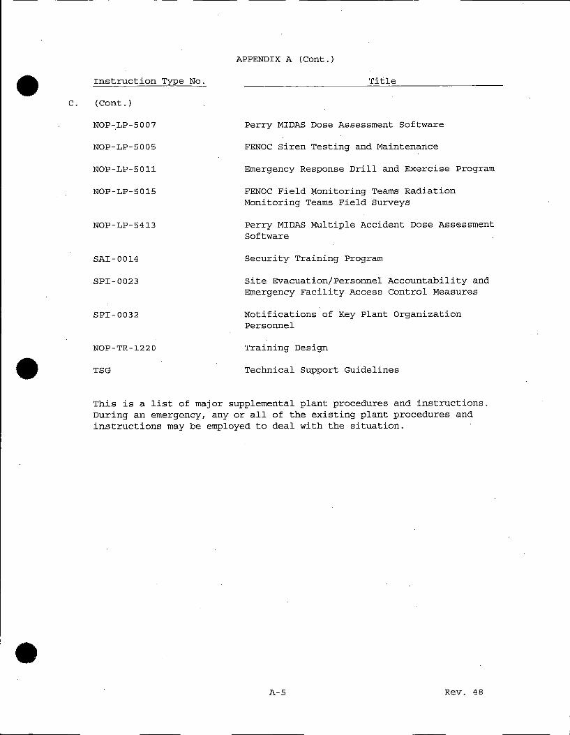
• c.
•
•
Instruction Type No.
(Cont.)
NOP-LP-5007
NOP-LP-5005
NOP-LP-5011
NOP-LP-5015
NOP-LP-5413
SAI-0014
SPI-0023
SPI-0032
NOP-TR-1220
TSG
APPENDIX A (Cont.)
Title
Perry MIDAS Dose Assessment Software
FENOC Siren Testing and Maintenance
Emergency Response Drill and Exercise Program
FENOC Field Monitoring Teams Radiation Monitoring Teams Field Surveys
Perry MIDAS Multiple Accident Dose Assessment Software
Security Training Program
Site Evacuation/Personnel Accountability and Emergency Facility Access Control Measures
Notifications of Key Plant Organization Personnel
Training Design
Technical Support Guidelines
This is a list of major supplemental plant procedures and instructions. During an emergency, any or all of the existing plant procedures and instructions may be employed to deal with the situation .
A-5 Rev. 48

•
•
•
APPENDIX B
LETTERS OF AGREEMENT
B-1 Rev. 48

LETTERS OF AGREEMENT
Title
Institute of Nuclear Power Operations
Perry Township Joint Fire District
Lake Hospital System, Inc.
Lake County
Ashtabula County
Geauga County
State of Ohio, Agreement with FirstEnergy
General Electric BWR Emergency Support Program
Auburn Career Center
Metro Health Medical Center (Metro General Hospital and Life Flight Services)
NOTE
Letters of agreement will be reviewed on an annual basis to ensure that they are current and continue in effect. Any agreement, written as a formal contract, will be considered effective for the specified duration.
Hard copies of the current Letters of Agreement (LOA) a~~ maintained current by the Emergency Response Section.
Letters of agreement with the Lake County Sheriff Office and other Federal, State, and local law enforcement agencies (LLEAs) are updated if required, as part of the Perry Plant Security Plan.
Rev. 48
•
•
•

•
APPENDIX C
LIST OF EMERGENCY EQUIPMENT AND SUPPLIES
•
• C-1 Rev. 48

APPENDIX C
LIST OF EMERGENCY EQUIPMENT AND SUPPLIES
A. PORTABLE RADIOLOGICAL MONITORING EQUIPMENT AND SUPPLIES
1.
2.
3.
4.
5.
6.
7.
LOCATION(l)
RMT
KITS
Emergency Operations Facility<2 • 3 l x
Training and Education Center x
Technical Support Center
Off site Alternate Tsc< 2 • 3 l x
Operations Support Center
Primary Access Control Point
Unit 1 Control Room(4)
PORTABLE
RADIACS DOSIMETRY
x
x x
x
x
x x
x
x
PROTECTIVE
CLOTHING
x
x
x
B. DECONTAMINATION EQUIPM.ENT AND SUPPLIES (l,S)
Storage Locations
1. Emergency Operations Facility (EOF)
- Decontamination Room
2 . Training and Education Center
- Decontamination Room
3. Operations Support Center (OSC)
- Decontamination Room
NOTE 1 .
Specific area locations are designated in PSI-0018. Detailed listings of equipment types, sizes and amounts are specified in equipment inventory checklists maintained by ERS, with the exception of the OSC (599' CC) Decontamination Room which is maintained under normal Radiation Protection Program.
NOTE 2
RMT kits are available at the EOF/Offsite Alternate TSC in case the plant site is inaccessible.
C-2 Rev. 48
•
•
•

•
•
•
APPENDIX C (Cont.)
NOTE 3
Dosimetry is available for RMT personnel at the EOF and offsite alternate TSC at the Concord Service Center.
NOTE 4
Sufficient equipment and supplies shall be stored in or adjacent to the Control Room, or immediately available upon request, to ensure continued manning of the Unit 1 Control Room.
NOTE 5
Decontaminants and supplies approved by NOP-OP-4503, including those required for the removal of radio-iodine contamination, will be maintained at designated decon locations .
C-3 Rev. 48

•
APPENDIX D
• LIST OF SUPPORTING PLANS
• D-1 Rev. 48

APPENDIX D
LIST OF SUPPORTING PLANS
1. THE OHIO PLAN FOR RESPONSE TO RADIATION EMERGENCIES AT COMMERCIAL NUCLEAR POWER PLANTS
2. COUNTY RADIATION EMERGENCY PLANS
a. ASHTABULA COUNTY RADIOLOGICAL EMERGENCY RESPONSE PLAN
b. GEAUGA COUNTY RADIOLOGICAL EMERGENCY RESPONSE PLAN
c. LAKE COUNTY RADIOLOGICAL EMERGENCY RESPONSE PLAN FOR THE PERRY NUCLEAR POWER PLANT, ANNEX M, APPENDIX 2-RADIATION PROTECTION.
3 . U.S. NUCLEAR REGULATORY COMMISSION
a. Response Coordination Manual, 1996 (NUREG/BR-0230)
4. EMERGENCY PUBLIC INFORMATION ORGANIZATION INSTRUCTIONS MANUAL
5 . PNPP SECURITY PLAN
6. FENOC QUALITY ASSURANCE PROGRAM MANUAL
7. UNITED STATES COAST GUARD
a. Captain of the Port, Cleveland; Contingency Plan for Perry Nuclear Power Plant
8. INSTITUTE OF NUCLEAR POWER OPERATIONS
a. Emergency Responses Manual (INPO 86-032)
D-2 Rev. 48
•
•
•

•
•
•
APPENDIX E
NUREG~0654/FEMA-REP-1 CROSS. REFERENCE TO PERRY PLANT EMERGENCY PLAN.INDEX
E-1 Rev. 48

APPENDIX E
NUREG-0654/FEMA-REP-l CROSS REFERENCE TO PERRY PLANT EMERGENCY PLAN INDEX
NUREG-0654 REFERENCE <S00555>
A. Assignment of Responsibility (Organization Control)
l.
2.
3.
a)
b)
c)
d)
e)
Federal, State, and local response organizations for emergency planning zone
Organizational and suborganizational concept of operation
Interrelationship (Block Diagram)
Individual in charge, by title
24-hour manning of communications
Written agreements and legal instruments
Title of the individual responsible for assuring continuity of resources (technical, administrative, and material) for continuous (24-hour) operations during a protracted period
B. Onsite Emergency Organization
l.
2.
3.
4.
Onsite emergency organization and relation to responsibilities and duties of normal staff complement
Emergency Coordinator with authority to initiate emergency actions
Line of succession for Emergency Coordinator
Functional responsibilities assigned to Emergency Coordinator
E-2
Section
3.2.l, 3.2.2, 3.2.3 5 .3, 5 .4
5.2
Figure 5-l Figure 5-2
·Figure 6-l Figure 6-3
5.2
5.2.3
5.3 5.4
·Appendix B
5.2.2
5.l 5.2.l
5.2.l
5.2.2.l 5.2.2.3 5.2.2.4 5.2.3
5.2.2.l 5.2.2.3 s.2.2.4 5.2.3
Rev. 48
•
•
•

•
•
•
B.
APPENDIX E (Cont.)
Onsite Emergency Organization (Cont.)
5. Emergency functions and minimum staffing for nuclear power plant emergencies
6. Interfaces between licensee, local services, and State and Local government
7. Corporate management, administrative and technical support personnel who will augment plant staff in:
8.
9.
a) Logistics support
b) Technical support
c) Interface with government authorities
d) Information to news media
Contractor and private organizations who may provide technical assistance
Services to be provided by local agencies, police, ambulance, medical, hospital, and firefighting
C. Emergency Response Support and Resources
1.
2.
3.
4.
a)
b)
c)
a)
Person(s) authorized to request Federal assistance
Federal resources expected
Specific licensee resources available to support the Federal response
Licensee shall prepare for the dispatch of a representative to the principle offsite governmental emergency operations centers
Radiological laboratories that can be used in an emergency
Organizations, facilities, and individuals that can be relied upon in an emergency to provide assistance
E-3
Section
5.2.l 5.2.2 Table 5-l
5.3 5.4 6.l Figure 6-3
5.2.2 5,2.3 Figure 5-l Figure 5-2
5.4.6 Appendix B
5.3 Appendix B
5.2.2, 5.4.3, 5.4.4
5.4.3
7.l.3, 7.l.4, 7.2.2.1
5.2.3
7.5.8
5.3, 5.4 Appendix B
Rev. 48

D.
APPENDIX E (Cont.)
Emergency Classification System
1.
2.
Instruments, parameters, or equipment status for establishing emergency class
Initiating conditions NUREG-0610 and postulated accidents in USAR
Section
Table 4-1
Figure 4-1
E. Notification Methods and Procedures
1.
2.
3.
4.
5.
6.
Procedures for notification of response organizations including means of message verification
Procedures for notifying, alerting, and mobilizing emergency personnel
Contents of initial emergency messages to be sent from plant
Follow-up messages from facility to off site authorities
Administrative and physical means to notify the public
Provide supporting information for written messages to the public for protective actions
6.1
6 .1.1 7.3
6.1
6.1
6.4.2 7.4
6.1, 8.6
6.4.2,
F. Emergency Communications
1. a) 24 hour day notification to include 24 hour communication link
5.2.3, 6.1, 7.2.2
b) Communications with contiguous state 5.4.5 and local governments
c) Communications with federal agencies 6.1, 7.2.2
d) Communications between near site EOF, 7.2 State and local EOCs, and RMTs
e) Alerting and activating emergency personnel 6.1.1, 7.3
f) Communications between operator, NRC 6.1, 7.2.2 headquarters, NRC regional EOC, and site EOF
E-4 Rev. 48
•
•
•

•
•
•
APPENDIX E (Cont.)
F. Emergency Communications (Cont.)
2. Communications for fixed and mobile support
3. Periodic testing of communications
G. Public Information
1.
2.
3.
4.
5.
Periodic dissemination of information
Public information program
a)
b)
a)
b)
c)
Contact and physical location for use by news media
Provide space for news media at near site EOF
Spokesperson for all necessary information
Arrangements for timely exchange of information
Arrangements for dealing with rumors
Annual program to acquaint news media with Emergency Plan and contact for release of public information
H: Emergency Facilities and Equipment
1.
2.
3.
TSC and osc in accordance with NUREG-0696
EOF in accordance with NUREG-0696
Means for activating and staffing facilities and centers
4. Onsite monitoring systems used to initiate emergency measures and for continuing assessment
a) Geophysical phenomena monitors
E-5
Section
6.4.2 7.2.2.5
8.8.4.2
8.6
8.6
5.2.2.5, 5. 2. 2. 6,
7 .1.4
7 .1.3
5.2.2.5, 5.2.2.6
7 .1.4 7.2.2.4
7 .1.4
8.7 Table 8-1
7 .1.1 7 .1.2
7 .1.3
5.2.3, 7.3
7.5.5, 7.5.6, 7.5.9,
Rev. 48

H.
APPENDIX E (Cont.)
Emergency Facilities and Equipment (Cont.)
b) Radiological monitors
c) Process monitors
d) Fire and combustion products
5. Off site monitoring equipment
6.
7.
·3.
a) Geophysical phenomena monitors
b) Radiological monitors
c) Lab facilities
Provide off site radiological m.oni taring equipment
Meteorological instrumentation and provision to obtain representative real-time meteorological information from another source
Provide onsite osc (assembly area)
9. Emergency equipment inventory/instrument checks and calibration
10. Inventory of emergency kits (appendix)
11. Central point to collect field monitoring data
I. Accident Assessment
1.
2.
Plant parameter values or other information which correspond to initiation conditions of NUREG-0610
Onsite capability and resources to provide initial values and continuing assessment of accident
3 . Methods and techniques for determining:
a) Source terms. bf releases of radioactive material
E-6
Section
7.5.3, .7.5·.9, Table 4-1
7.5.1
7.5.4
7.5.9.1
7.5.3
7.5.8
6.2, 6.4.2, 7.7
7.5.7
5.2.2 7 .1.2
7. 7, 8 .4
Appendix C
6.4.2, 7.1.3
Table 4-1 Appendix A
5.2.3 7.5
6.4.1, 7.5.10 Figure 6-4
Rev. 48
•
•
•

•
•
• l
I.
APPENDIX E (Cont.)
Accident Assessment (Cont.)
4.
5.
6.
7.
8.
9.
b) Magnitude of release based on plant system parameters and monitors
Establish relationship between effluent monitor readings and onsite and offsite exposures for various meteorological conditions
Meteorological information at EOF; TSC, Control Room, and offsite NRC center
Methodology for determining the release rate/projected dose if instrumentation is off scale or inoperable
Field monitoring within the plume exposure Emergency Planning Zone
Methods, equipment and expertise to make rapid assessments of any radiological hazards through liquid or gaseous releases
Capability to detect and measure radioiodine concentrations in air as low as 1.0 E-07 uci/cc under field conditions
10. Accident assessment/dose estimating
J. Protective Response
1.
2.
3.
4.
Means and time required to warn and advise onsite individuals and individuals in areas controlled by operator
Evacuation routes and transportation for onsite individuals to a suitable offsite location
Radiological monitoring of people evacuated from site
Evacuation of onsite non-essential personnel in the event of a Site Area or General Emergency, provision for decontamination capability at or near offsite location
E-7
Section
7.5.10
7.5.10
7.1, 7.2.2.l(c), 7.5.10
7.5.10.2
5.2.3, 6.4.2 7.5.10
5.2.3, 6.4.2, 7 .. 5
5.2.2.2 6.2.5
7.5.10
6 .1.1 6.4.1 7.2.1.2
6.3 Figure 6-2
6.3, 7.1.3, Appendix C
6.3 7 .1. 3 Appendix C
Rev. 48

J.
APPENDIX E (Cont.)
Protective Response (Cont.)
5.
6.
7.
8.
9.
Capability to account for all individuals onsite within 30 minutes
a) Individual respiratory protection
b) Use of protective clothing
c) Use of radioprotective drugs
Mechanism for recommending protective actions to state and local authorities
Time estimate for evacuation within plume exposure EPZ
a)
~)
c)
d)
Maps showing evacuation routes, relocation centers, hospital, shelter areas, and other medical facilities
Population distribution around facility
Means for notifying all segments of transient and resident population
Bases for choice of recommended protective actions from plume exposure pathway
K. Radiological Exposure Control
1. Exposure guidelines for:
a) Removal of injured persons
b) Undertaking corrective actions
c) Performing assessment action
d) Providing first aid
e) Performing personnel decontamination
f) Providing ambulance service
g) Providing medical treatment services
E-8
Section
6.3
6.6
6.5, 6.6
6.7
6 .1, 6 .4,
6.4.2
6.4.2 PSI-0013
PSI-0013
2.2 PSI-0013
6.4.2, 7.4, PSI-0013
6.4.1, 6.4.2, Table 6-2 Figure 6-3
6 .5, 6 .6
Rev. 48
•
•
•

•
•
•
K.
APPENDIX E (Cont.)
Radiological Exposure Control (Cont.)
2.
3.
4.
Onsite radiation protection program for emergencies
Emergency worker dosimetry provisions and record-keeping
a)
b)
Action levels for determining need for decontamination
Radiological decontamination of emergency personnel and waste disposal
5. Contamination control for:
6.
a)
b)
c)
Area access control
Drinking water and food supplies
Criteria fo.r permitting return of area and items.to normal use
Capability for decontaminating relocated onsite personnel
L. Medical and Public Health Support
1.
2.
3.
Local and backup medical facilities with ability for radiological evaluation of victims; adequate training of medical personnel
Onsite first aid capability
Transportation of accident victims
M. Recovery and Reentry Planning & Postaccident Operations
1.
2.
Procedures for re-entry/recovery
Position/title authority and responsibilities of key positions in recovery organization
E-9
Section
6 .5, 6. 6
6.6
6.5.3
6.5 7.6
6.5
6.5
6.5
6. 3' 7. 6
5.3.3 Table 8-1
7.6 8.1.2.4
5.3.3 Table 8-1
9.0
9.2
Rev. 48

M.
APPENDIX E (Cont.)
Recovery and Reentry Planning & Postaccident Operations (Cont.)
3.
4.
Means of informing m~mbers of the response organizations that recovery operation is to be initiated and of any changes in organizational structure that may occur.
Estimating total population exposure
N. Exercises and Drills
1.
2.
a) Initial arid annual emergency response exercise
b)-lMobilization of local and state and resources
b) -2 Critique of annual exercise
b)-3 Scenario preparation
b) -4 Drills on back shifts
a)
b)
c)
d)
e)
Communications testing
Fire drills
Medical emergency drills
Radiological monitoring drills
Radiation Protection drills
1) Airborne and liquid sample and direct radiation measurement in environment
3. Scenarios include:
a)
b)
c)
Basic objective
Dates, times, places, and participating organizations
Simulated events
E-10
• Section
9.3
7.5.10, 9.2
8.8.4.1
8.8.4.1
8.8.3
8.8.2
8.8.4.1
8.8.4.2 • 8.8
8.8.4.4
8.8.4.5
8.8.4.3
8.8.1.1
8.8.1.2
8.8.1.3
• Rev. 48
_ __J

•
•
•
APPENDIX E (Cont.}
N. Exercises and Drills (Cont.}
d} Time schedule of real and simulated initiating events
e} Narrative summary
f} Qualified observers
4. State, Federal, and local observers; formal evaluation of exercises
5. Means for corrective action; management control over corrective actions
0. Radiological Emergency Response Training
1.
2.
3.
a} Provide site specific emergency response training for offsite emergency organizations who provide assistance
Onsite training program shall include practical drills and on-the-spot correction of erroneous performa,nce
Training for first aid teams shall include The American National Red Cross, The American He~rt Association or equivalent first .aid and cardiopulmonary resuscitation (CPR} training.
4 . Training program for:
a}
b}
c}
d}
e}
f}
Directors or coordinators of response organizations
Personnel responsible for accident assessment
Radiological monitoring teams
Police and fire fighting personnel
Repair and damage control teams (onsite}
First aid and rescue personnel
E-11
Section
8.8.1.4
8.8.1.5
8.8.1.6
8.8.1.5, 8.8.3
8.8.3
8.1.1.6 Table 8-1
8 .1.2
8.1.2.4
8.1.2.2
8.1.2.5
8.1.2.2
Table 8-1
8.1.2.2
8.1.2.4 Table 8-1
Rev. 48

0.
APPENDIX E (Cont.)
Radiological Emergency Response Training (Cont.)
5.
g) Local support services personnel including Civil Defense/Emergency Service personnel
h) Medical support personnel
i) Operators headquarters support personnel
j) Communicators
Initial and annual retraining of personnel with emergency response responsibilities
P. Responsibility for the Planning Effort: Development, Periodic Review and Distribution of Emergency Plan
1. Training for planners
2. Person responsible for Radiological Emergency Response Planning
3 . Person responsible for development and updating of Emergency Plan
4 . Annual updating of plans
5. Distribution of plans and revisions
6. Detailed list of supporting plans
7. List of procedures to implement the plan
8. Table of Contents, Index, and cross reference to NUREG-0654
9. Independent audits of the emergency preparedness program
10. Update of emergency telephone numbers quarterly
.E-12
Section
8.1.1.6 Table 8-1
Table 8-1
8.1.2.2
8.1.2.2
8.1.2.l 8.1.2.2
8.1.1.8
8 .1.1
8 .1.1
8.2
8.2
Appendix
Appendix
Table of Contents Appendix
8.3
8.5
D
A
E-
Rev. 48
•
•
•

J
Enclosure B L-16-276
Acknowledgement of Receipt

Enclosure B
PERRY NUCLEAR POWER PLANT
UNIT 1
Controlled Document Instruction Sheet
Title: Emergency Plan for Perry Nuclear Power Plant Docket No's, 50-440 Revision 48
Letter Number: L-16-276 ERS Number: ERS-16-0018
Control Number: 242
To: Mr. Dennis Hagan Document Control Desk
Insert Remove 4 7 and Replace with Rev 48 Entire Document

Enclosure B
FIRSTENERGY CORPORATION
PERRY NUCLEAR POWER PLANT
UNIT 1
ACKNOWLEDGEMENT OF RECEIPT
Title: Emergency Plan for Perry Nuclear Power Plant Docket No's, 50-440 . Revision 48
Control Number: 242 From: Mr. Dennis Hagan Document Control Desk
Letter Number: L-16-276 ERS Number: ERS-16-0018 Letter Dated: September 16, 2016
Signature
Title
Return to:
Date
Perry Nuclear Power Plant Attention: L. VanDerHorst A240
P.O. Box 97 Perry, Ohio 44081

fl) C
l)
0 ! co .....
:::s N
fl) I
..2 co - u
I
c ...J
ca w
E
E
:::s
UJ

ENCLOSURE C
Perry Nuclear Power Plant EP 0000 Revision 48
Change Summary
Revision 48 of EP 0000, Emergency Plan for Perry Nuclear Power Plant. Docket Nos. 50-440 contained the following changes:
Several changes were made throughout the PNPP Emergency Plan to eliminate the Onsite Alternate Technical Support Center (TSC) and the Onsite Public Information Response Team (PIRT) facilities located in the Training Education Center.
The PIRT and Alternate TSC are located in the Emergency Operations Facility (EOF) at the Concord Service Center outside of the 10 Mile Emergency Planning Zone (EPZ).
The elimination of the Onsite Alternate TSC and PIRT was evaluated in 10CFR5050.47(q) PY-2016-008-00 and found to be consistent with 10CFR50.47(b) and 10CFR50, Appendix E requirements and not cause a reduction in effectiveness of the Emergency Plan.