Enclosure 4, Slide Presentation, Modular Composite Walls ...
15
Modular Composite Walls Subjected to Combined Thermal and Mechanical Loads Sanj Malushte, PhD, PE, SE Amit H. Varma, PhD Bechtel Fellow & Sr. Principal Engineer Associate Professor Bechtel Power Corporation Purdue University Members, AISC Subcommittee for Modular Composite Construction Introduction Bechtel has investigated a modular wall system through two technical grants Preliminary design has been conducted in-house in Bechtel and further analytical/experimental investigations have been conducted at Purdue University The Bechtel Modular Wall concept has now been further refined and extended to modular flooring This presentation focuses on the effects of combined thermal and mechanical loading on MC walls Ongoing work focuses on: Development of b/t limits, fire behavior, axial load capacity Development of interaction equation for multi-axial forces Participation in the development of AISC design specification
Transcript of Enclosure 4, Slide Presentation, Modular Composite Walls ...
Modular Composite Walls Subjected to Combined Thermal and Mechanical Loads
Sanj Malushte, PhD, PE, SE Amit H. Varma, PhDBechtel Fellow & Sr. Principal Engineer Associate Professor
Bechtel Power Corporation Purdue University
Members, AISC Subcommittee for Modular Composite Construction
Introduction
Bechtel has investigated a modular wall system through two technical grantsPreliminary design has been conducted in-house in Bechtel and further analytical/experimental investigations have been conducted at Purdue UniversityThe Bechtel Modular Wall concept has now been further refined and extended to modular flooringThis presentation focuses on the effects of combined thermal and mechanical loading on MC wallsOngoing work focuses on:
Development of b/t limits, fire behavior, axial load capacityDevelopment of interaction equation for multi-axial forcesParticipation in the development of AISC design specification
Behavior Combined Thermal and Mechanical Load
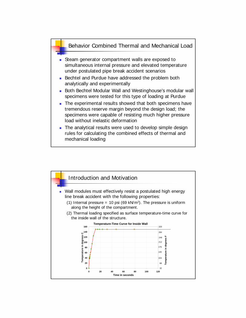
Steam generator compartment walls are exposed to simultaneous internal pressure and elevated temperature under postulated pipe break accident scenariosBechtel and Purdue have addressed the problem both analytically and experimentallyBoth Bechtel Modular Wall and Westinghouse’s modular wall specimens were tested for this type of loading at PurdueThe experimental results showed that both specimens have tremendous reserve margin beyond the design load; the specimens were capable of resisting much higher pressure load without inelastic deformationThe analytical results were used to develop simple design rules for calculating the combined effects of thermal and mechanical loading
Introduction and Motivation
Wall modules must effectively resist a postulated high energy line break accident with the following properties:(1) Internal pressure = 10 psi (69 kN/m2). The pressure is uniform
along the height of the compartment. (2) Thermal loading specified as surface temperature-time curve for
the inside wall of the structure. Temperature-Time Curve for Inside Wall
0
20
40
60
80
100
120
140
160
0 20 40 60 80 100 120Time in seconds
Tem
pera
ture
in d
egre
es C
68
104
140
176
248
32
212
284
320
Tem
pera
ture
in d
egre
es F
Impetus for Experimental Investigations
Preliminary analytical investigations of an SG compartment indicated the general behavior of SC walls under combined thermal and mechanical loadingExperimental investigation and verification of the analytical results was deemed ESSENTIAL to determine:
Yielding and/or bucking (if any) of the steel faceplates occurs in compression or tensionThe effectiveness of composite action from shear connectors under combined thermal and mechanical loading (deleterious effects, if any, of concrete cracking on the behavior of shearconnectors)The extent of concrete cracking under thermal loading and its influence on section properties and deflections
EXPERIMENTAL INVESTIGATIONS
Objectives: The experimental investigations were conducted to address the inherent limitations of the analytical modeling, toverify the performance of this structure, and to evaluate the combined effects of thermal and mechanical loading.
Limitations: Full-scale experimental investigations of the complete SG compartment with SC walls is impractical. Large-scale investigation of even one SC wall was impractical.
Hence, the experiments were conducted on a representativestrip of the SC wall. This strip well captured the predominant one-way bending behavior of the SC wall. The specimens were “full-scale” in that they employed the same concrete and steel plate thicknesses and comparable bending span as the actual wall of an SG compartment

EXPERIMENTAL INVESTIGATIONS
EXPERIMENTAL INVESTIGATIONS
SPECIMEN DETAILS
30 in.
30 in.
22 ft.
1/2 in. steel plate
Steel frames to connect plates
Shear studs @ 10 in. spacing
End rigging and support assembly

EXPERIMENTAL INVESTIGATIONS
SPECIMEN CASTING DETAIL
Concrete Infill
Steel plates vertical during casting.
Specimen rotated 90o after set.
SC Specimen
22 ft. long.
2.5 ft x 2.5 ft. cross-section 22 ft.
30 in.
Load
ing
Fram
e
Load
ing
Fram
e
Heater controls
EXPERIMENTAL INVESTIGATIONS
PLAN VIEW OF STRUCTURAL SETUP
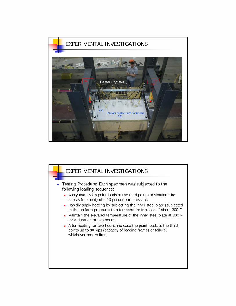
EXPERIMENTAL INVESTIGATIONS
6 ft.
4 ft.Radiant heaters with controllers
Heater ControlsP P
EXPERIMENTAL INVESTIGATIONS
Testing Procedure: Each specimen was subjected to the following loading sequence:
Apply two 25 kip point loads at the third points to simulate theeffects (moment) of a 10 psi uniform pressure. Rapidly apply heating by subjecting the inner steel plate (subjected to the uniform pressure) to a temperature increase of about 300 F.Maintain the elevated temperature of the inner steel plate at 300 F for a duration of two hours.After heating for two hours, increase the point loads at the third points up to 90 kips (capacity of loading frame) or failure, whichever occurs first.
Specimen 1: Heating Phase
-0.12
-0.08
-0.04
0
0.04
0.08
0.12
0 11 22
Beam Length (ft)
Def
lect
ion
(in)
0 minutes 5 minutes 10 minutes 15 minutes 120 minutes
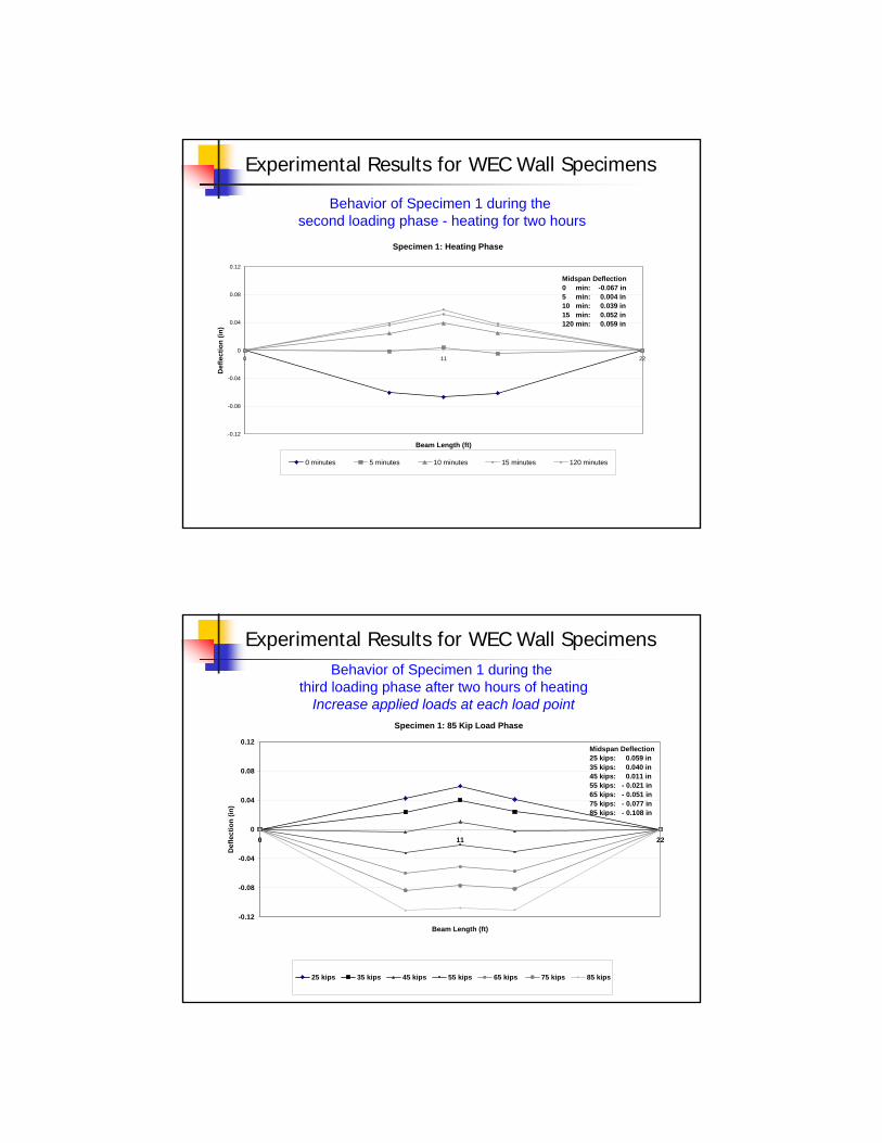
Midspan Deflection0 min: -0.067 in5 min: 0.004 in10 min: 0.039 in15 min: 0.052 in120 min: 0.059 in
Behavior of Specimen 1 during the second loading phase - heating for two hours
Experimental Results for WEC Wall Specimens
Specimen 1: 85 Kip Load Phase
-0.12
-0.08
-0.04
0
0.04
0.08
0.12
0 11 22
Beam Length (ft)
Def
lect
ion
(in)
25 kips 35 kips 45 kips 55 kips 65 kips 75 kips 85 kips
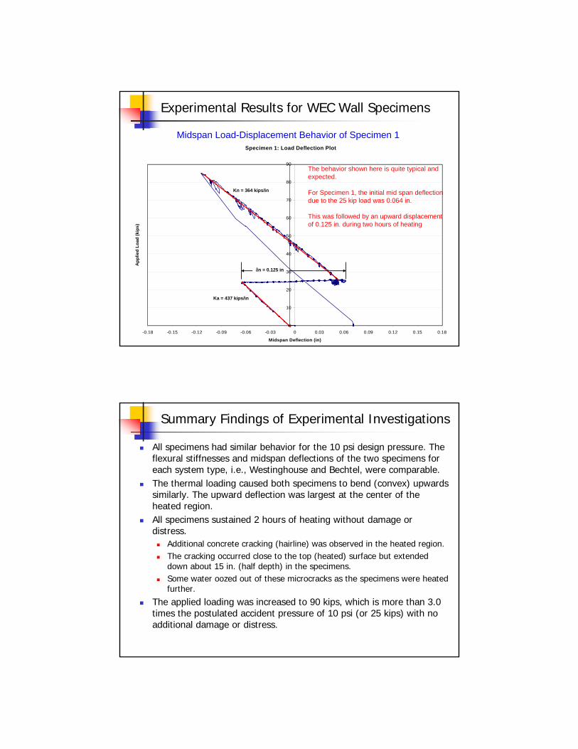
Midspan Deflection25 kips: 0.059 in35 kips: 0.040 in45 kips: 0.011 in55 kips: - 0.021 in65 kips: - 0.051 in75 kips: - 0.077 in85 kips: - 0.108 in
Behavior of Specimen 1 during the third loading phase after two hours of heating
Increase applied loads at each load point
Experimental Results for WEC Wall Specimens
Experimental Results for WEC Wall Specimens
Specimen 1: Load Deflection Plot
0
10
20
30
40
50
60
70
80
90
-0.18 -0.15 -0.12 -0.09 -0.06 -0.03 0 0.03 0.06 0.09 0.12 0.15 0.18
Midspan Deflection (in)
App
lied
Load
(kip
s)
δn = 0.125 in
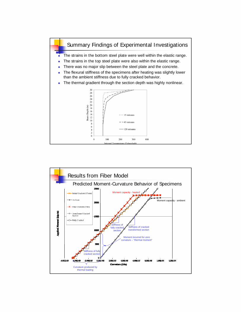
Kn = 364 kips/in
Ka = 437 kips/in
Midspan Load-Displacement Behavior of Specimen 1
The behavior shown here is quite typical and expected.
For Specimen 1, the initial mid span deflection due to the 25 kip load was 0.064 in.
This was followed by an upward displacement of 0.125 in. during two hours of heating
Summary Findings of Experimental Investigations
All specimens had similar behavior for the 10 psi design pressure. The flexural stiffnesses and midspan deflections of the two specimens for each system type, i.e., Westinghouse and Bechtel, were comparable. The thermal loading caused both specimens to bend (convex) upwards similarly. The upward deflection was largest at the center of the heated region. All specimens sustained 2 hours of heating without damage or distress.
Additional concrete cracking (hairline) was observed in the heated region. The cracking occurred close to the top (heated) surface but extendeddown about 15 in. (half depth) in the specimens.Some water oozed out of these microcracks as the specimens were heated further.
The applied loading was increased to 90 kips, which is more than 3.0 times the postulated accident pressure of 10 psi (or 25 kips) with no additional damage or distress.
Summary Findings of Experimental Investigations
The strains in the bottom steel plate were well within the elastic range.The strains in the top steel plate were also within the elastic range.There was no major slip between the steel plate and the concrete.The flexural stiffness of the specimens after heating was slightly lower than the ambient stiffness due to fully cracked behavior. The thermal gradient through the section depth was highly nonlinear.
0 40 80 120 160
Sect
ion
dept
h (in
.)
30
22
45 minutes
120 minutes
Temperature (oC)
Predicted Moment-Curvature Behavior of Specimens
Results from Fiber Model
Stiffness of cracked transformed section
Moment capacity - ambient
Moment incurred for zero curvature – “thermal moment”
Curvature produced by thermal loading
Stiffness of fully cracked section
Stiffness of fully cracked
section
Moment capacity - heated

Results from Fiber Model
Strains and stresses for 25 kip loading - ambient conditions - phase 1(Moment = 2400 k-in.)
Experimental Temperature Gradient
0
5
10
15
20
25
30
0 20 40 60 80 100 120 140
Temperature Change (Celsius)
Results from Fiber Model
Thermal gradient and mechanical strains after two hours of heating - phase 2
25 kips, 150 Celsius
0
5
10
15
20
25
30
-0.001 -0.0005 0 0.0005 0.001
Strain
Mech. strain = Total strain - Thermal strain
Thermal strain = α ΔT
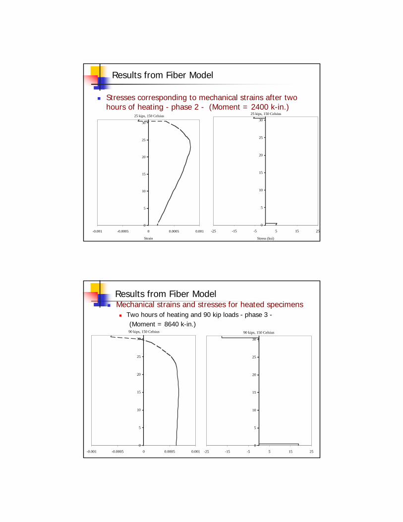
Results from Fiber Model
Stresses corresponding to mechanical strains after two hours of heating - phase 2 - (Moment = 2400 k-in.)
25 kips, 150 Celsius
0
5
10
15
20
25
30
-25 -15 -5 5 15 25
Stress (ksi)
25 kips, 150 Celsius
0
5
10
15
20
25
30
-0.001 -0.0005 0 0.0005 0.001
Strain
90 kips, 150 Celsius
0
5
10
15
20
25
30
-0.001 -0.0005 0 0.0005 0.001
St i
90 kips, 150 Celsius
0
5
10
15
20
25
30
-25 -15 -5 5 15 25
St (k i)
Results from Fiber ModelMechanical strains and stresses for heated specimens
Two hours of heating and 90 kip loads - phase 3 -(Moment = 8640 k-in.)

Predicting Beam Behavior
Moment-area method to integrate the section moment-curvature relationships along the length to predict member behavior. Alternately, use conjugate beam method or numerical integration analysis method.
SP1 Δmid = -0.067 inSP2 Δmid = -0.071 inFM Δmid = -0.065 in
-0.1
-0.08
-0.06
-0.04
-0.02
00 132 264
Beam Length (in)
Bea
m D
efle
ctio
n (in
)
Fiber Model Specimen 1 Specimen 2
Predicting Beam Specimen Behavior
Good comparisons between experimental and predicted behavior.
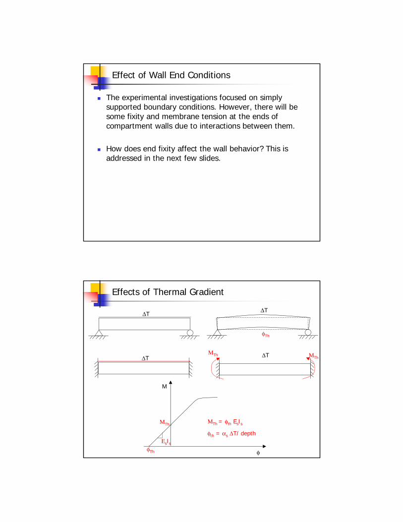
Effect of Wall End Conditions
The experimental investigations focused on simply supported boundary conditions. However, there will be some fixity and membrane tension at the ends of compartment walls due to interactions between them.
How does end fixity affect the wall behavior? This is addressed in the next few slides.
Effects of Thermal Gradient
ΔT ΔT
ΔT ΔTΜTh ΜTh
φTh
ΜTh
ΕsIs
ΜTh = φth EsIs
φth = αs ΔT/ depth
M
φ
φTh

Effects of Fixed Boundary and Thermal Gradient
ΜThΜTh +
w L2/12 -+
w L2/24
w L2/12-
wΔT
Mmax = wL2/24 + Mth
σmax = (wL2/24 + Mth) x (d/2) / Is
σmax = T/ As + (wL2/24 + Mth) x (d/2) / IsWhen membrane tension is also present:
Discussion of findings
Ambient stiffness of the composite walls can be predicted using cracked transformed section properties.The stiffness of the composite wall subjected to heating (to 300F) can be predicted using fully cracked (steel only) section properties. This is similar to the behavior of RC sections. The specimens resisted moments and shears for pressures well in excess of three times the expected design pressure of 10-psi.
No visible distress/abrupt stiffness reduction, shear connector failure, local buckling of steel plate, loss in through-thickness shear strength, etc was noticed at these loads, thus indicating further reserve margins.
The fiber model approach predicts the experimental results with reasonable accuracy. A simple equation was developed (based on the analytical results) to predicts the effects of combined thermal and mechanical loading.
This equation is valid for all types of SC systems

Acknowledgments
Bechtel CorporationPurdue University Bowen Laboratory