
ENCLOSED CONDUCTOR SYSTEM KBH - vahle.com · 5 TECHNICAL DATA CONDUCTOR SYSTEM VALUES: ELECTRICAL...
36
ENCLOSED CONDUCTOR SYSTEM KBH 4B | EN 2019
Transcript of ENCLOSED CONDUCTOR SYSTEM KBH - vahle.com · 5 TECHNICAL DATA CONDUCTOR SYSTEM VALUES: ELECTRICAL...
ENCLOSED CONDUCTOR SYSTEM KBH
4B | EN 2019

2
3
ENCLOSED CONDUCTOR SYSTEM KBH
CONTENTEnclosed conductor system KBH ...............................................................3
Technical data .............................................................................................4
Jointing material, hangers & end caps ......................................................8
Brackets .......................................................................................................9
End feeds, line feeds ............................................................................... 10
Line feeds ................................................................................................. 11
Terminal box ............................................................................................. 12
Heating...................................................................................................... 14
Contact sections, turntables & switches ................................................ 16
Transfer funnels ........................................................................................17
Transfer guides ......................................................................................... 18
Transfer guides & conductor dead section ............................................. 19
Removing section ..................................................................................... 20
Maintenance sections ............................................................................. 21
Anti-condensation section ....................................................................... 22
Expansion section .................................................................................... 23
Single current collector .............................................................................24
Double collector & tow arms ................................................................... 25
Flexible tow arm ....................................................................................... 26
Examples for ordering ...............................................................................27
Spare part list ........................................................................................... 29
APOS Positioning system ......................................................................... 30
VAHLE Powercom®.....................................................................................31
Questionnaire ........................................................................................... 32
Pictures of plants ..................................................................................... 33
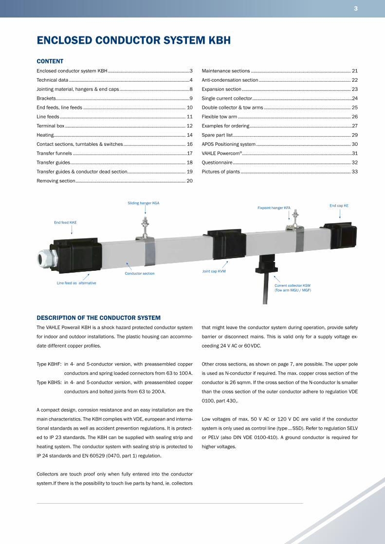
DESCRIPTION OF THE CONDUCTOR SYSTEMThe VAHLE Powerail KBH is a shock hazard protected conductor system
for indoor and outdoor installations. The plastic housing can accommo-
date different copper profiles.
Type KBHF: in 4- and 5-conductor version, with preassembled copper
conductors and spring loaded connectors from 63 to 100 A.
Type KBHS: in 4- and 5-conductor version, with preassembled copper
conductors and bolted joints from 63 to 200 A.
A compact design, corrosion resistance and an easy installation are the
main characteristics. The KBH complies with VDE, european and interna-
tional standards as well as accident prevention regulations. It is protect-
ed to IP 23 standards. The KBH can be supplied with sealing strip and
heating system. The conductor system with sealing strip is protected to
IP 24 standards and EN 60529 (0470, part 1) regulation.
Collectors are touch proof only when fully entered into the conductor
system.If there is the possibility to touch live parts by hand, ie. collectors
that might leave the conductor system during operation, provide safety
barrier or disconnect mains. This is valid only for a supply voltage ex-
ceeding 24 V AC or 60 VDC.
Other cross sections, as shown on page 7, are possible. The upper pole
is used as N-conductor if required. The max. copper cross section of the
conductor is 26 sqmm. If the cross section of the N-conductor Is smaller
than the cross section of the outer conductor adhere to regulation VDE
0100, part 430,.
Low voltages of max. 50 V AC or 120 V DC are valid if the conductor
system is only used as control line (type … SSD). Refer to regulation SELV
or PELV (also DIN VDE 0100-410). A ground conductor is required for
higher voltages.
End feed KKE
Line feed as alternative
Conductor section
Sliding hanger KGA
Joint cap KVM
Current collector KSW(Tow arm MGU / MGF)
Fixpoint hanger KFA End cap KE

4
TECHNICAL DATA
APPLICATIONSFor mobile power consumers like cranes, monorails, electric hoists, ma-
chine tools, automated storage and retrieval systems, lighting systems.
APPROVALSUL-approved
HOUSINGColor grey, plastic housing for 4 or 5 conductors.
Standard section 4 m. Other sections are available. The ground conduc-
tor is identified by international color code. Phase reversing prevented
by design of the collector and housing. Higher number of conductors
possible by combination of several conductor systems.
COUPLINGSThrough plastic joint caps.
FEED SETSThrough line feeds or end feeds.
When selecting the “overload” protection devices, selection has to be
made according to DIN VDE 0100 part 530.
END CAPSThe open ends of the conductor system are closed by end caps for KBHF
and KBHS.
HANGERSSupport bracket at the crane track (see page 9). Max. support distance
of the conductor at following ambient temperatures:
• Indoor systems and roofed outdoor systems: ≤ 35°C = 2.00 m
• Indoor and outdoor systems
with and without heating: > 35°C = 1.33 m
• Cold storage ≤ 0°C = 1.33 m
It is necessary to provide at least one additional hanger on the sections
of the feeds (line feeds), removing sections, anti-condensation sections
and expansion sections (1 m sections). This prevents any sagging of the
conductor conductor system.
EXPANSION DURING TEMPERATURE FLUCTUATIONThe expansion sections are required to compensate the different expan-
sions between copper conductors and steel- or concrete structures, in
varying temperatures without interrupting electrical power. The different
expansions between the plastic housing and the copper conductors will
be compensated in every joint.
ANTI-CONDENSATION SECTIONSThese sections are used for transfer of the Powerail to outdoor areas to
avoid condensation. The conductor system is not separated electrically.
CONTACT SECTIONS, TURNTABLES AND SWITCHESConductor sections for working areas and transfer applications see page
17 and 19.
SECTIONALIZINGConductor dead sections are electrical interrupts of the conductor. Un-
der normal operating conditions a cross over with collectors to switch the
voltage off or on is only allowed with low power ratings (control current).
The conductors can be seperated through air gaps (5 mm) or insulating
pieces (35 mm). With the air gap the collector carbon bridges the gap,
e. g. for mains. The insulating piece is longer than the carbon and each
conductor section can be separated electrically, e. g. for control. Double
isolating sections are recommended to guarantee safely separated con-
ductor sections as per EN 60204.
COLLECTORSThe current collectors are made of re-inforced polyester fiberglass, for
high strength and light weight. Spring loaded carbon brushes maintain
uniform contact. Connecting cables and hinged or flexible towing arms
included.
The length of the connecting cable may not exceed 3 m if the added over-
load protection device is not designed for the load capacity of this cable.
Refer also to regulation VDE 0100, part 430 and EN 60204-32. (Note:
this occurs often with several collectors per system).
CONTINUITY OF GROUND CONDUCTORThe continuity of the ground conductor has to be guaranteed as per reg-
ulation EN60204-32 for conductor rails.
Runways of lifting devices may not be used as ground conductor, only
an additional connection is permissible. Therefore a continuous ground
conductor is required.
WITH FOLLOWING SYSTEM REQUIREMENTS DOUBLE COLLECTORS HAVE TO BE USED• as proper measure to fulfil the continuity of the ground conductor
system via carbon brushes. Refer to regulation EN 60204-1-2007-06
and EN 60204-32-2009-03.
• Transfers with switches and turntables
• Operational voltage below 50 V
• low voltages, frequency controlled drives
• Transmission of data- and/or emergency stop signals
• high electrical loads
REMOVING SECTION FOR COLLECTORSAssembly and disassembly of the collector is possible at the end of the
track as well as at the removing section. By opening and closing the slid-
5
TECHNICAL DATA
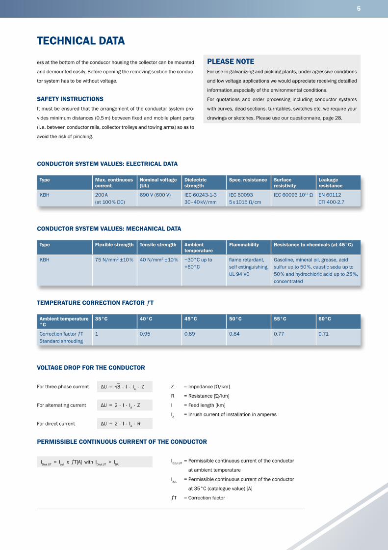
CONDUCTOR SYSTEM VALUES: ELECTRICAL DATA
Type Max. continuous current
Nominal voltage (UL)
Dielectric strength
Spec. resistance Surface resistivity
Leakage resistance
KBH 200 A (at 100 % DC)
690 V (600 V) IEC 60243-1-330–40 kV/mm
IEC 600935 x 1015 Ω/cm
IEC 60093 1013 Ω EN 60112 CTI 400-2.7
CONDUCTOR SYSTEM VALUES: MECHANICAL DATA
Type Flexible strength Tensile strength Ambient temperature
Flammability Resistance to chemicals (at 45°C)
KBH 75 N/mm2 ±10 % 40 N/mm2 ±10 % −30°C up to +60°C
flame retardant,self extinguishing,UL 94 V0
Gasoline, mineral oil, grease, acid sulfur up to 50 %, caustic soda up to 50 % and hydrochloric acid up to 25 %, concentrated
Ambient temperature °C
35°C 40°C 45°C 50°C 55°C 60°C
Correction factor ƒTStandard shrouding
1 0.95 0.89 0.84 0.77 0.71
TEMPERATURE CORRECTION FACTOR ƒT
PERMISSIBLE CONTINUOUS CURRENT OF THE CONDUCTOR
VOLTAGE DROP FOR THE CONDUCTOR
For three-phase current
For alternating current
For direct current
ΔU = √3 · I · IA · Z
ΔU = 2 · I · IA · Z
ΔU = 2 · I · IA · R
Z = Impedance [Ώ/km]
R = Resistance [Ώ/km]
I = Feed length [km]
IA = Inrush current of installation in amperes
IDzul.UT = Permissible continuous current of the conductor
at ambient temperature
Izul. = Permissible continuous current of the conductor
at 35°C (catalogue value) [A]
ƒT = Correction factor
ers at the bottom of the conducor housing the collector can be mounted
and demounted easily. Before opening the removing section the conduc-
tor system has to be without voltage.
SAFETY INSTRUCTIONSIt must be ensured that the arrangement of the conductor system pro-
vides minimum distances (0.5 m) between fixed and mobile plant parts
(i. e. between conductor rails, collector trolleys and towing arms) so as to
avoid the risk of pinching.
PLEASE NOTEFor use in galvanizing and pickling plants, under agressive conditions
and low voltage applications we would appreciate receiving detailled
information,especially of the environmental conditions.
For quotations and order processing including conductor systems
with curves, dead sections, turntables, switches etc. we require your
drawings or sketches. Please use our questionnaire, page 28.
IDzul.UT = Izul. x ƒT[A] with IDzul.UT > IDA
6
(1) ... Suffix types e. g. 2 m KBHF4/63-2000HSC, Order No. 600972, shorter legths are made up from the next larger standard length.(2) In case of using a conductor as N see page 3.(3) 5th. Conductor max. 80 A at 100 % DC.(4) Nominal voltage UL= 600 V(5) Vontrol line(6) Power consumption UL on request
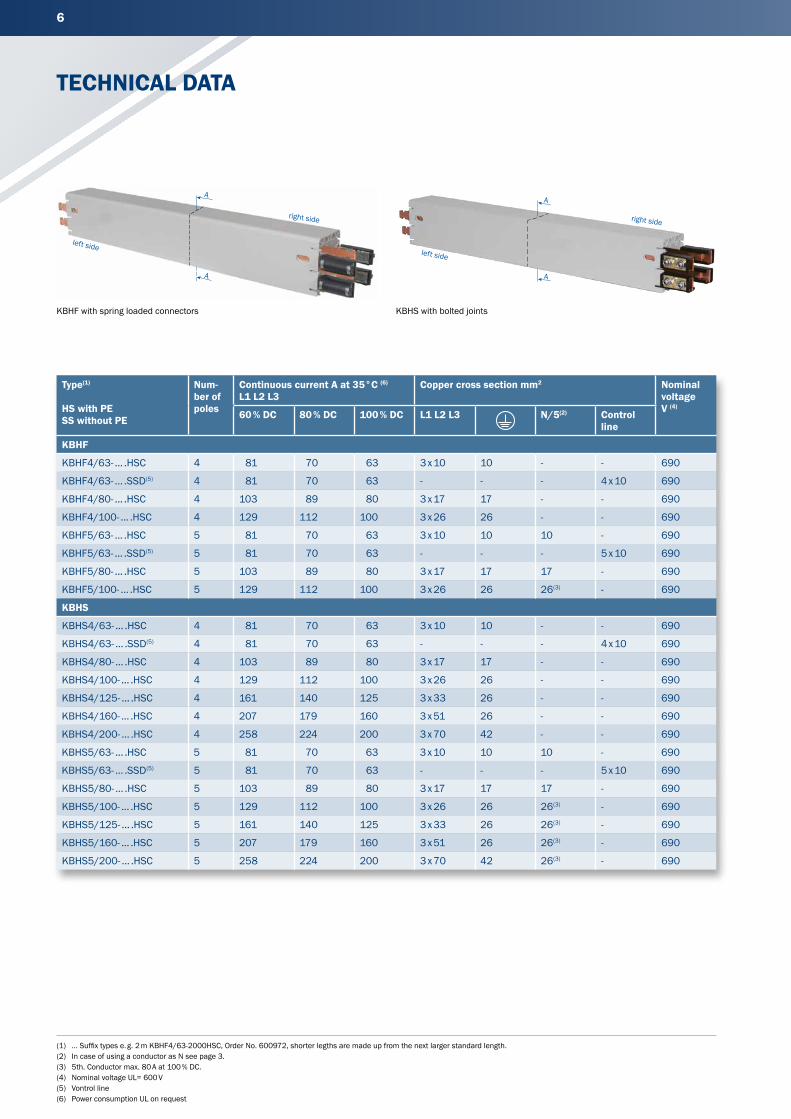
TECHNICAL DATA
Type(1)
HS with PESS without PE
Num-ber of poles
Continuous current A at 35°C (6)
L1 L2 L3Copper cross section mm2 Nominal
voltageV (4)
60 % DC 80 % DC 100 % DC L1 L2 L3 N/5(2) Control line
KBHF
KBHF4/63- ... .HSC 4 81 70 63 3 x 10 10 - - 690
KBHF4/63- ... .SSD(5) 4 81 70 63 - - - 4 x 10 690
KBHF4/80- ... .HSC 4 103 89 80 3 x 17 17 - - 690
KBHF4/100- ... .HSC 4 129 112 100 3 x 26 26 - - 690
KBHF5/63- ... .HSC 5 81 70 63 3 x 10 10 10 - 690
KBHF5/63- ... .SSD(5) 5 81 70 63 - - - 5 x 10 690
KBHF5/80- ... .HSC 5 103 89 80 3 x 17 17 17 - 690
KBHF5/100- ... .HSC 5 129 112 100 3 x 26 26 26(3) - 690
KBHS
KBHS4/63- ... .HSC 4 81 70 63 3 x 10 10 - - 690
KBHS4/63- ... .SSD(5) 4 81 70 63 - - - 4 x 10 690
KBHS4/80- ... .HSC 4 103 89 80 3 x 17 17 - - 690
KBHS4/100- ... .HSC 4 129 112 100 3 x 26 26 - - 690
KBHS4/125- ... .HSC 4 161 140 125 3 x 33 26 - - 690
KBHS4/160- ... .HSC 4 207 179 160 3 x 51 26 - - 690
KBHS4/200- ... .HSC 4 258 224 200 3 x 70 42 - - 690
KBHS5/63- ... .HSC 5 81 70 63 3 x 10 10 10 - 690
KBHS5/63- ... .SSD(5) 5 81 70 63 - - - 5 x 10 690
KBHS5/80- ... .HSC 5 103 89 80 3 x 17 17 17 - 690
KBHS5/100- ... .HSC 5 129 112 100 3 x 26 26 26(3) - 690
KBHS5/125- ... .HSC 5 161 140 125 3 x 33 26 26(3) - 690
KBHS5/160- ... .HSC 5 207 179 160 3 x 51 26 26(3) - 690
KBHS5/200- ... .HSC 5 258 224 200 3 x 70 42 26(3) - 690
A
A
left side
right side
KBHF with spring loaded connectors
A
A
left side
right side
KBHS with bolted joints

7
• The last number of the order specifies the section length. Please suffix the order number with 1, 2, 3, 4. Ground = PE
Numbers in paranthesis apply to control line
TECHNICAL DATA
Leakage distance mm
Impedance at 50 Hertz and 20°C Ω / 1000 m
Resistance at 20°CΩ / 1000 m
Weight kg /m Order No. (1)
Phase N Phase N
33 1.728 1.728 - 1.717 1.717 - 1.304 600 97•
33 1.728 - - 1.717 - - 1.304 600 99•
33 1.074 1.074 - 1.057 1.057 - 1.536 600 98•
33 0.712 0.712 - 0.687 0.687 - 1.864 600 02•
33 1.728 1.728 1.728 1.717 1.717 1.717 1.410 601 00•
33 1.728 - 1.728 1.717 - 1.717 1.410 601 02•
33 1.074 1.074 1.074 1.057 1.057 1.057 1.700 601 01•
33 0.712 0.712 0.712 0.687 0.687 0.687 2.110 600 12•
33 1.782 1.728 - 1.717 1.717 - 1.424 601 03•
33 1.728 - - 1.717 - - 1.424 601 05•
33 1.074 1.074 - 1.057 1.057 - 1.656 601 04•
33 0.712 0.712 - 0.687 0.687 - 1.984 600 06•
33 0.579 0.712 - 0.549 0.687 - 2.161 600 07•
30 0.383 0.712 - 0.344 0.687 - 2.699 600 08•
27 0.299 0.457 - 0.254 0.429 - 3.297 600 31•
33 1.728 1.728 1.728 1.717 1.717 1.717 1.560 601 06•
33 1.728 - 1.728 1.717 - 1.717 1.560 601 08•
33 1.074 1.074 1.074 1.057 1.057 1.057 1.850 601 07•
33 0.712 0.712 0.712 0.687 0.687 0.687 2.260 600 16•
33 0.579 0.712 0.712 0.549 0.687 0.687 2.437 600 17•
30 0.383 0.712 0.712 0.344 0.687 0.687 2.926 600 18•
27 0.299 0.457 0.457 0.254 0.429 0.687 3.573 600 32•
70
54
L1(2)
L2(1)
L3(4)
(3)
9
green(dark grey)
yellow(dark grey)
Safety web
70
54
L1(2)
L2(1)
L3(4)
(3)
9
N/5
Safety web
green(dark grey)
yellow(dark grey)
8
(1) ... / K with stainless screws All steel metal components
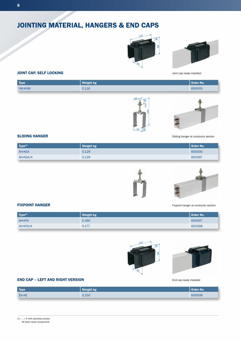
JOINTING MATERIAL, HANGERS & END CAPS
JOINT CAP, SELF LOCKING
Type Weight kg Order No.
VM-KVM 0.116 600005
Joint cap ready installed
Sliding hanger at conductor section
Fixpoint hanger at conductor section
End cap ready installed
SLIDING HANGER
Type(1) Weight kg Order No.
AH-KGA 0.129 600000
AH-KGA/K 0.129 600397
FIXPOINT HANGER
Type(1) Weight kg Order No.
AH-KFA 0.160 600007
AH-KFA/K 0.177 600398
END CAP – LEFT AND RIGHT VERSION
Type Weight kg Order No.
EK-KE 0.150 600008
130
17
90
89
M8
max
. 35
142
58 35
130
17
90
89
9
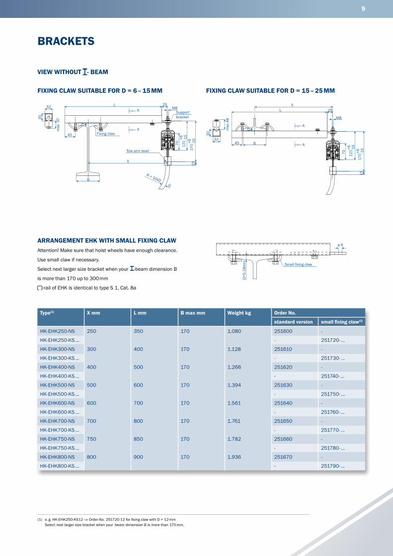
(1) e. g. HK-EHK250-KS12 → Order-No. 251720-12 for fixing claw with D = 12 mm Select next larger size bracket when your -beam dimension B is more than 170 mm.
BRACKETS
Type(1) X mm L mm B max mm Weight kg Order No.
standard version small fixing claw(1)
HK-EHK250-NS 250 350 170 1.080 251600 -
HK-EHK250-KS ... - 251720- ...
HK-EHK300-NS 300 400 170 1.128 251610 -
HK-EHK300-KS ... - 251730- ...
HK-EHK400-NS 400 500 170 1.266 251620 -
HK-EHK400-KS ... - 251740- ...
HK-EHK500-NS 500 600 170 1.394 251630 -
HK-EHK500-KS ... - 251750- ...
HK-EHK600-NS 600 700 170 1.561 251640 -
HK-EHK600-KS ... - 251760- ...
HK-EHK700-NS 700 800 170 1.761 251650 -
HK-EHK700-KS ... - 251770- ...
HK-EHK750-NS 750 850 170 1.782 251660 -
HK-EHK750-KS ... - 251780- ...
HK-EHK800-NS 800 900 170 1.936 251670 -
HK-EHK800-KS ... - 251790- ...
FIXING CLAW SUITABLE FOR D = 6 – 15 MM FIXING CLAW SUITABLE FOR D = 15 – 25 MM
ARRANGEMENT EHK WITH SMALL FIXING CLAWAttention! Make sure that hoist wheels have enough clearance.
Use small claw if necessary.
Select next larger size bracket when your -beam dimension B
is more than 170 up to 300 mm
-rail of EHK is identical to type S 1, Cat. 8a
32
30
max
. 37
45
L 25M8
170
+6 -15
121
+6 -15
70
15
A
A
BD
R = 10xD
D
X
Fixing claw
Tow arm level
Supportbracket
30
32
max
.48
D
XL
45 B
A
A
25
M8
1517
0+6 -1
5
121+6 -1
5
70
D=5
-18m
mø 9
Small fi xing claw
VIEW WITHOUT - BEAM
10
Feeds in the curve area on request.(1) Both cable glands are attached to the packing unit.
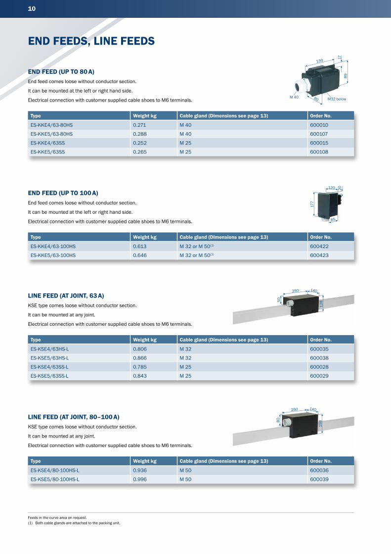
END FEEDS, LINE FEEDS
END FEED (UP TO 100 A)End feed comes loose without conductor section.
It can be mounted at the left or right hand side.
Electrical connection with customer supplied cable shoes to M6 terminals.
LINE FEED (AT JOINT, 63 A)KSE type comes loose without conductor section.
It can be mounted at any joint.
Electrical connection with customer supplied cable shoes to M6 terminals.
LINE FEED (AT JOINT, 80–100 A)KSE type comes loose without conductor section.
It can be mounted at any joint.
Electrical connection with customer supplied cable shoes to M6 terminals.
Type Weight kg Cable gland (Dimensions see page 13) Order No.
ES-KKE4/63-80HS 0.271 M 40 600010
ES-KKE5/63-80HS 0.288 M 40 600107
ES-KKE4/63SS 0.252 M 25 600015
ES-KKE5/63SS 0.265 M 25 600108
Type Weight kg Cable gland (Dimensions see page 13) Order No.
ES-KSE4/63HS-L 0.806 M 32 600035
ES-KSE5/63HS-L 0.866 M 32 600038
ES-KSE4/63SS-L 0.785 M 25 600028
ES-KSE5/63SS-L 0.843 M 25 600029
Type Weight kg Cable gland (Dimensions see page 13) Order No.
ES-KKE4/63-100HS 0.613 M 32 or M 50(1) 600422
ES-KKE5/63-100HS 0.646 M 32 or M 50(1) 600423
Type Weight kg Cable gland (Dimensions see page 13) Order No.
ES-KSE4/80-100HS-L 0.936 M 50 600036
ES-KSE5/80-100HS-L 0.996 M 50 600039
END FEED (UP TO 80 A)End feed comes loose without conductor section.
It can be mounted at the left or right hand side.
Electrical connection with customer supplied cable shoes to M6 terminals. 90
130 1789
M 40 M32 below
120 20
177
85
250 140
12850
250 140
15880
11
Feeds in the curve area on request.
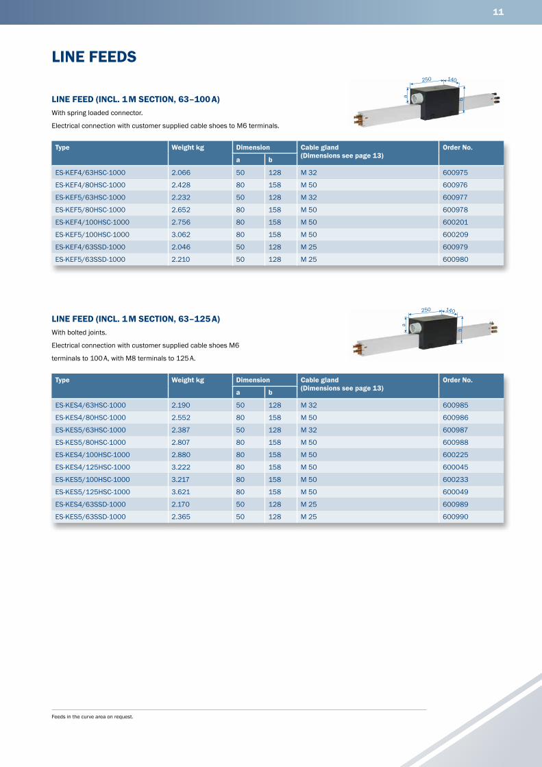
LINE FEEDS
LINE FEED (INCL. 1 M SECTION, 63–100 A)With spring loaded connector.
Electrical connection with customer supplied cable shoes to M6 terminals.
LINE FEED (INCL. 1 M SECTION, 63–125 A)With bolted joints.
Electrical connection with customer supplied cable shoes M6
terminals to 100 A, with M8 terminals to 125 A.
Type Weight kg Dimension Cable gland(Dimensions see page 13)
Order No.
a b
ES-KEF4/63HSC-1000 2.066 50 128 M 32 600975
ES-KEF4/80HSC-1000 2.428 80 158 M 50 600976
ES-KEF5/63HSC-1000 2.232 50 128 M 32 600977
ES-KEF5/80HSC-1000 2.652 80 158 M 50 600978
ES-KEF4/100HSC-1000 2.756 80 158 M 50 600201
ES-KEF5/100HSC-1000 3.062 80 158 M 50 600209
ES-KEF4/63SSD-1000 2.046 50 128 M 25 600979
ES-KEF5/63SSD-1000 2.210 50 128 M 25 600980
Type Weight kg Dimension Cable gland(Dimensions see page 13)
Order No.
a b
ES-KES4/63HSC-1000 2.190 50 128 M 32 600985
ES-KES4/80HSC-1000 2.552 80 158 M 50 600986
ES-KES5/63HSC-1000 2.387 50 128 M 32 600987
ES-KES5/80HSC-1000 2.807 80 158 M 50 600988
ES-KES4/100HSC-1000 2.880 80 158 M 50 600225
ES-KES4/125HSC-1000 3.222 80 158 M 50 600045
ES-KES5/100HSC-1000 3.217 80 158 M 50 600233
ES-KES5/125HSC-1000 3.621 80 158 M 50 600049
ES-KES4/63SSD-1000 2.170 50 128 M 25 600989
ES-KES5/63SSD-1000 2.365 50 128 M 25 600990
250 140
a b
250 140
a
b
12
Feeds in the bow area on request.(1) Fixing borings ø 7 mm at the bottom of the box.
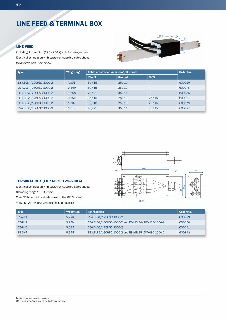
LINE FEED & TERMINAL BOX
LINE FEEDincluding 1 m section (125 – 200 A) with 2 m single cores
Electrical connection with customer supplied cable shoes
to M6 terminals. See below.
TERMINAL BOX (FOR KELS, 125–200 A)Electrical connection with customer supplied cable shoes.
Clamping range 16 – 95 mm2.
View “A” Input of the single cores of the KELS (a. m.)
View “B” with M 63 (Dimensions see page 13)
Type Weight kg Cable cross section in mm2 / Ø in mm Order No.
L1–L3 Ground N / 5
ES-KELS4/125HSC-1000-2 7.803 35 / 16 25 / 10 - 600069
ES-KELS4/160HSC-1000-2 9.690 50 / 18 25 / 10 - 600075
ES-KELS4/200HSC-1000-2 11.668 70 / 21 35 / 11 - 600385
ES-KELS5/125HSC-1000-2 9.150 35 / 16 25 / 10 25 / 15 600077
ES-KELS5/160HSC-1000-2 11.037 50 / 18 25 / 10 25 / 15 600079
ES-KELS5/200HSC-1000-2 13.014 70 / 21 35 / 11 25 / 15 600387
Type Weight kg For feed line Order No.
ES-ZK1 5.228 ES-KELS4/125HSC-1000-2 600389
ES-ZK2 5.276 ES-KELS4/160HSC-1000-2 and ES-KELS4/200HSC-1000-2 600390
ES-ZK3 5.595 ES-KELS5/125HSC-1000-2 600391
ES-ZK4 5.645 ES-KELS5/160HSC-1000-2 and ES-KELS5/200HSC-1000-2 600392
400
360(1)
200
160
120“B”“A”
140250
128
50
13
(1) The max. single length is 40 m long. For further distances are joint laces necessary. For each meter system length have 2 m sealing strip to beordered. The delivery will be in pairs.
CURVES, SEALING STRIP & CABLE GLANDS FOR FEEDS
CABLE GLANDS FOR FEEDS
SEALING STRIP (INCLUDING ACCESSORIES)
CURVES
For Type Cable gland For cable diam. in mm Power rating in A Page
ES-KKE ... M50 27–35 63–100 HS 10
ES-KKE ... M40 17–28 63 / 80 HS 10
ES-KKE ... M32 15–21 63 SS 10
ES-KSE / KEF / KES ... M32 17–26 63 HS 10 and 11
ES-KSE / KEF / KES ... M50 23–34 80–100 HS 10 and 11
ES-KES ... M50 29–40 125 HS 11
ES-ZK1–4 ... (Page B) M63 27–48 125 / 160 / 200 HS 12
BH-AKB-KBH ... M25 9–19 - 15
ES-KKE / KSE / KEF / KES ... M25 9–19 63 SS 10 and 11
Type Description Order No.
DL-D-KBH-MKH-MKL-TDV Sealing strip(1) 600551
DL-F-KBH Fixing clamp for sealing strip (1 per end) 600354
DL-V-KSLT-KBH-MKL/H-LSV/G Coupling for sealing strip (2 for each joint) 258300
DL-EZRD-KBH Mounting glider for sealing strip 600109
SA-ZB-DG-KSW-S Sealing strip slide plate for collectors KSW 600640
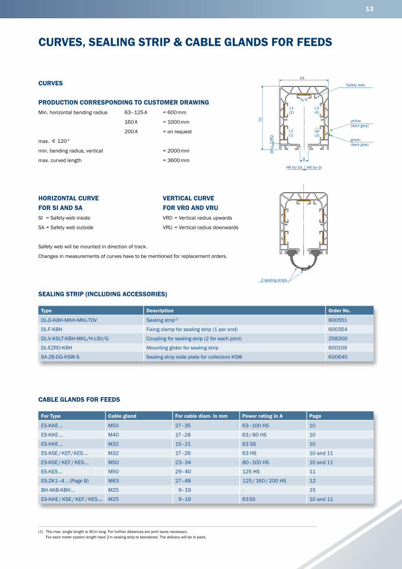
PRODUCTION CORRESPONDING TO CUSTOMER DRAWINGMin. horizontal bending radius 63–125 A = 600 mm
160 A = 1000 mm
200 A = on request
max. ∢ 120°
min. bending radius, vertical = 2000 mm
max. curved length = 3600 mm
SI = Safety-web inside
SA = Safety web outside
Safety web will be mounted in direction of track.
Changes in measurements of curves have to be mentioned for replacement orders.
HORIZONTAL CURVE FOR SI AND SA
VERTICAL CURVE FOR VRO AND VRU
2 sealing strips
VRO = Vertical radius upwards
VRU = Vertical radius downwards
54
70
9
L1(2)
L2(1)
L3(4)
(3)
N/5
VRU
VRO
Safety web
green(dark grey)
yellow(dark grey)
HR for SA HR for SI
14
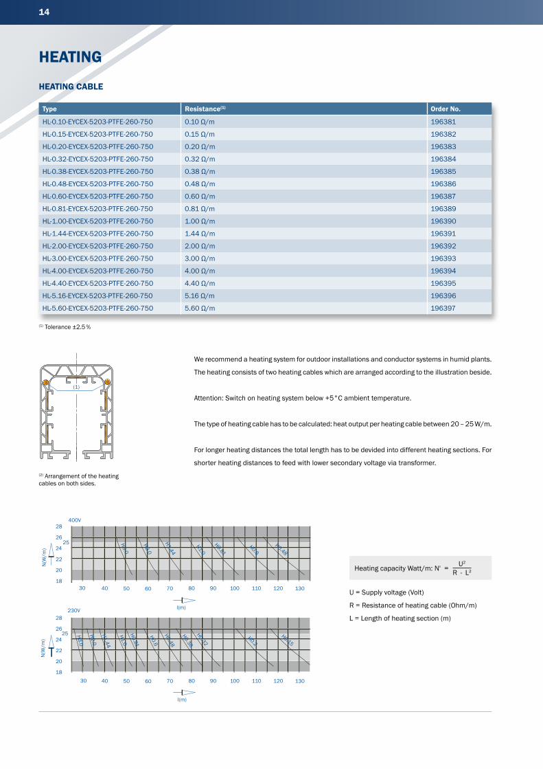
HEATING
We recommend a heating system for outdoor installations and conductor systems in humid plants.
The heating consists of two heating cables which are arranged according to the illustration beside.
Attention: Switch on heating system below +5°C ambient temperature.
The type of heating cable has to be calculated: heat output per heating cable between 20 – 25 W/m.
For longer heating distances the total length has to be devided into different heating sections. For
shorter heating distances to feed with lower secondary voltage via transformer.
U = Supply voltage (Volt)
R = Resistance of heating cable (Ohm/m)
L = Length of heating section (m)
(1) Tolerance ±2.5 %
HEATING CABLE
(2) Arrangement of the heating cables on both sides.
(1)
Type Resistance(1) Order No.
HL-0.10-EYCEX-5203-PTFE-260-750 0.10 Ω/m 196381
HL-0.15-EYCEX-5203-PTFE-260-750 0.15 Ω/m 196382
HL-0.20-EYCEX-5203-PTFE-260-750 0.20 Ω/m 196383
HL-0.32-EYCEX-5203-PTFE-260-750 0.32 Ω/m 196384
HL-0.38-EYCEX-5203-PTFE-260-750 0.38 Ω/m 196385
HL-0.48-EYCEX-5203-PTFE-260-750 0.48 Ω/m 196386
HL-0.60-EYCEX-5203-PTFE-260-750 0.60 Ω/m 196387
HL-0.81-EYCEX-5203-PTFE-260-750 0.81 Ω/m 196389
HL-1.00-EYCEX-5203-PTFE-260-750 1.00 Ω/m 196390
HL-1.44-EYCEX-5203-PTFE-260-750 1.44 Ω/m 196391
HL-2.00-EYCEX-5203-PTFE-260-750 2.00 Ω/m 196392
HL-3.00-EYCEX-5203-PTFE-260-750 3.00 Ω/m 196393
HL-4.00-EYCEX-5203-PTFE-260-750 4.00 Ω/m 196394
HL-4.40-EYCEX-5203-PTFE-260-750 4.40 Ω/m 196395
HL-5.16-EYCEX-5203-PTFE-260-750 5.16 Ω/m 196396
HL-5.60-EYCEX-5203-PTFE-260-750 5.60 Ω/m 196397
Heating capacity Watt/m: N' = U2
R · L2
N(W
/m)
18
20
22
24
26
28
25
30 40 50 60 70 80 90 100 110 120 130
l(m)
400V
18
20
22
24
26
28
25
30 40 50 60 70 80 90 100 110 120 130
N(W
/m)
l(m)
230V
H0.15
H0.2
H0.32
H0.38
H0.48
H0.6
H0.81
H1.0
H1.44
H2.0
H0.48
H0.6
H0.81
H1.44
H2.0
H3.0
H3.0
H1.0
15
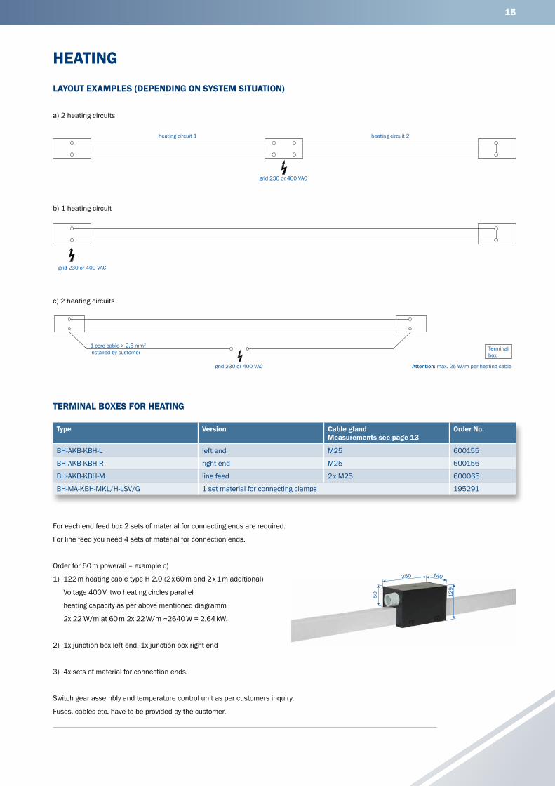
HEATING
For each end feed box 2 sets of material for connecting ends are required.
For line feed you need 4 sets of material for connection ends.
Order for 60 m powerail – example c)
1) 122 m heating cable type H 2.0 (2 x 60 m and 2 x 1 m additional)
Voltage 400 V, two heating circles parallel
heating capacity as per above mentioned diagramm
2x 22 W/m at 60 m 2x 22 W/m ~2640 W = 2,64 kW.
2) 1x junction box left end, 1x junction box right end
3) 4x sets of material for connection ends.
Switch gear assembly and temperature control unit as per customers inquiry.
Fuses, cables etc. have to be provided by the customer.
Type Version Cable glandMeasurements see page 13
Order No.
BH-AKB-KBH-L left end M25 600155
BH-AKB-KBH-R right end M25 600156
BH-AKB-KBH-M line feed 2 x M25 600065
BH-MA-KBH-MKL/H-LSV/G 1 set material for connecting clamps 195291
a) 2 heating circuits
b) 1 heating circuit
c) 2 heating circuits
TERMINAL BOXES FOR HEATING
LAYOUT EXAMPLES (DEPENDING ON SYSTEM SITUATION)
heating circuit 1 heating circuit 2
grid 230 or 400 VAC
grid 230 or 400 VAC
Attention: max. 25 W/m per heating cablegrid 230 or 400 VAC
1-core cable > 2,5 mm2 installed by customer
Terminal box
129
140250
50
16
(1) Contact sections must not be activated before collectors are fully engaged.
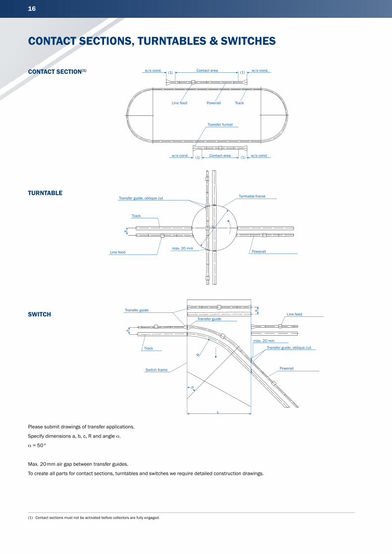
CONTACT SECTIONS, TURNTABLES & SWITCHES
Please submit drawings of transfer applications.
Specify dimensions a, b, c, R and angle α.
α = 50°
Max. 20 mm air gap between transfer guides.
To create all parts for contact sections, turntables and switches we require detailed construction drawings.
CONTACT SECTION(1)
TURNTABLE
SWITCH
(1) (1)
(1) (1)
b
a
a
a
R
c
�
Powerail
Transfer guide, oblique cut
Track
Transfer guide, oblique cut
max. 20 mm
Switch frame
Transfer guide
Track
w/o cond.
Transfer guideLine feed
Powerail
Line feedmax. 20 mm
Turntable frame
Line feed Powerail
w/o cond. Contact area w/o cond.
w/o cond.
Transfer funnel
Track
Contact area
17
(1) Corresponding to the center of collector(2) Also suitable for former 40 A-version
TRANSFER FUNNELS
Type Weight kg Order No.
Left version Right version
ET-KET4/63-125-L-HSC-500(2) 1.552 600285 -
ET-KET4/63-125-R-HSC-500(2) 1.493 - 600279
ET-KET4/160-L-HSC-500 1.636 600286 -
ET-KET4/160-R-HSC-500 1.562 - 600280
ET-KET4/200-L-HSC-500 1.786 600305 -
ET-KET4/200-R-HSC-500 1.688 - 600303
ET-KET5/63-125-L-HSC-500(2) 1.702 600288 -
ET-KET5/63-125-R-HSC-500(2) 1.632 - 600282
ET-KET5/160-L-HSC-500 1.784 600289 -
ET-KET5/160-R-HSC-500 1.701 - 600283
ET-KET5/200-L-HSC-500 1.934 600306 -
ET-KET5/200-R-HSC-500 1.823 - 600304
ET-KET4/63-L-SSD-500(2) 1.524 600287
ET-KET4/63-R-SSD-500(2) 1.524 - 600281
ET-KET5/63-L-SSD-500(2) 1.524 600290 -
ET-KET5/63-R-SSD-500(2) 1.524 - 600284
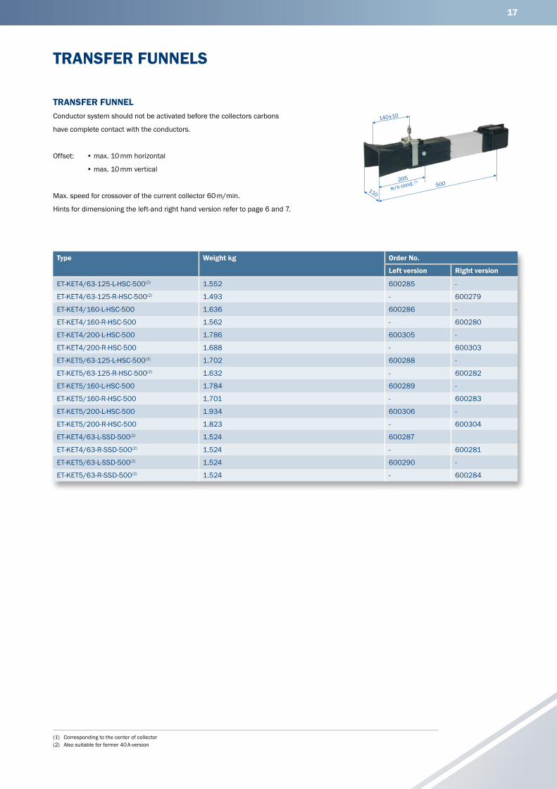
TRANSFER FUNNELConductor system should not be activated before the collectors carbons
have complete contact with the conductors.
Offset: • max. 10 mm horizontal
• max. 10 mm vertical
Max. speed for crossover of the current collector 60 m/min.
Hints for dimensioning the left-and right hand version refer to page 6 and 7.
500110
140±10
205
w/o cond. (1)
18
(1) Corresponding to the center of collector(2) Also suitable for former 40 A-version
Type Weight kg Order No.
Left version Right version
UE-KÜ4/63-125-L-HSC-350(2) 1.276 600261 -
UE-KÜ4/63-125-R-HSC-350(2) 1.276 - 600255
UE-KÜ4/160-L-HSC-350 1.351 600262 -
UE-KÜ4/160-R-HSC-350 1.351 - 600256
UE-KÜ4/200-L-HSC-350 1.490 600309 -
UE-KÜ4/200-R-HSC-350 1.490 - 600307
UE-KÜ5/63-125-L-HSC-350(2) 1.434 600264 -
UE-KÜ5/63-125-R-HSC-350(2) 1.434 - 600258
UE-KÜ5/160-L-HSC-350 1.509 600265 -
UE-KÜ5/160-R-HSC-350 1.509 - 600259
UE-KÜ5/200-L-HSC-350 1.648 600310 -
UE-KÜ5/200-R-HSC-350 1.648 - 600308
UE-KÜ4/63-L-SSD-350(2) 1.276 600263 -
UE-KÜ4/63-R-SSD-350(2) 1.276 - 600257
UE-KÜ5/63-L-SSD-350(2) 1.427 600266 -
UE-KÜ5/63-R-SSD-350(2) 1.427 - 600260
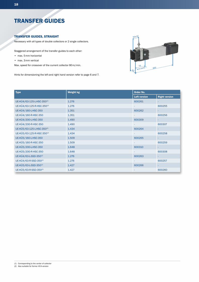
TRANSFER GUIDES, STRAIGHTNecessary with all types of double collectors or 2 single collectors.
Staggered arrangement of the transfer guides to each other:
• max. 5 mm horizontal
• max. 3 mm vertical
Max. speed for crossover of the current collector 80 m/min.
Hints for dimensioning the left-and right hand version refer to page 6 and 7.
TRANSFER GUIDES
35083
50±10
70
w/o cond. (1)
19
(1) Corresponding to the center of collector(2) Also suitable for former 40 A-version(3) Complete types e. g. ST-KTI3HS-L1/L2/L3-KSW for a 35 mm isolating piece with separation of cinductors L1, L2, L3 and 2 for the current collector KSW → Order-No.: 600295
TRANSFER GUIDES & CONDUCTOR DEAD SECTION
Type(1) Weight kg Order No.
Left version Right version
UE-KÜS4/63-125-L-HSC-350(2) 1.243 600273 -
UE-KÜS4/63-125-R-HSC-350(2) 1.243 - 600267
UE-KÜS4/160-L-HSC-350 1.324 600274 -
UE-KÜS4/160-R-HSC-350 1.324 - 600268
UE-KÜS4/200-L-HSC-350 1.517 600317 -
UE-KÜS4/200-R-HSC-350 1.517 - 600315
UE-KÜS5/63-125-L-HSC-350(2) 1.381 600276 -
UE-KÜS5/63-125-R-HSC-350(2) 1.381 - 600270
UE-KÜS5/160-L-HSC-350 1.447 600277 -
UE-KÜS5/160-R-HSC-350 1.447 - 600271
UE-KÜS5/200-L-HSC-350 1.668 600318 -
UE-KÜS5/200-R-HSC-350 1.668 - 600316
UE-KÜS4/63-L-SSD-350(2) 1.243 600275 -
UE-KÜS4/63-R-SSD-350(2) 1.243 - 600269
UE-KÜS5/63-L-SSD-350(2) 1.379 600278 -
UE-KÜS5/63-R-SSD-350(2) 1.379 - 600272
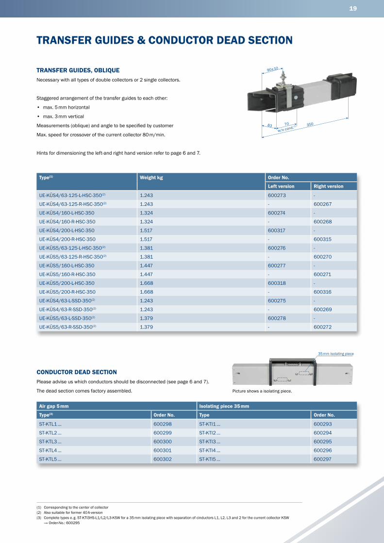
TRANSFER GUIDES, OBLIQUENecessary with all types of double collectors or 2 single collectors.
Staggered arrangement of the transfer guides to each other:
• max. 5 mm horizontal
• max. 3 mm vertical
Measurements (oblique) and angle to be specified by customer
Max. speed for crossover of the current collector 80 m/min.
Hints for dimensioning the left-and right hand version refer to page 6 and 7.
Air gap 5 mm Isolating piece 35 mm
Type(3) Order No. Type Order No.
ST-KTL1 ... 600298 ST-KTI1 ... 600293
ST-KTL2 ... 600299 ST-KTI2 ... 600294
ST-KTL3 ... 600300 ST-KTI3 ... 600295
ST-KTL4 ... 600301 ST-KTI4 ... 600296
ST-KTL5 ... 600302 ST-KTI5 ... 600297
CONDUCTOR DEAD SECTIONPlease advise us which conductors should be disconnected (see page 6 and 7).
The dead section comes factory assembled.
35083
90±10
70
w/o cond.(1)
35 mm isolating piece
Picture shows a isolating piece.
20
(1) Also suitable for former 40 A-version
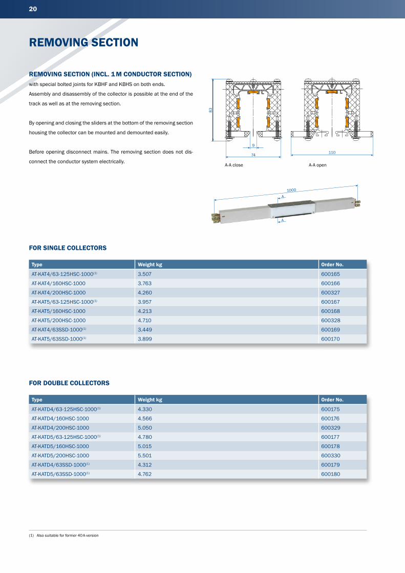
REMOVING SECTION
Type Weight kg Order No.
AT-KAT4/63-125HSC-1000(1) 3.507 600165
AT-KAT4/160HSC-1000 3.763 600166
AT-KAT4/200HSC-1000 4.260 600327
AT-KAT5/63-125HSC-1000(1) 3.957 600167
AT-KAT5/160HSC-1000 4.213 600168
AT-KAT5/200HSC-1000 4.710 600328
AT-KAT4/63SSD-1000(1) 3.449 600169
AT-KAT5/63SSD-1000(1) 3.899 600170
Type Weight kg Order No.
AT-KATD4/63-125HSC-1000(1) 4.330 600175
AT-KATD4/160HSC-1000 4.566 600176
AT-KATD4/200HSC-1000 5.050 600329
AT-KATD5/63-125HSC-1000(1) 4.780 600177
AT-KATD5/160HSC-1000 5.015 600178
AT-KATD5/200HSC-1000 5.501 600330
AT-KATD4/63SSD-1000(1) 4.312 600179
AT-KATD5/63SSD-1000(1) 4.762 600180
REMOVING SECTION (INCL. 1 M CONDUCTOR SECTION)with special bolted joints for KBHF and KBHS on both ends.
Assembly and disassembly of the collector is possible at the end of the
track as well as at the removing section.
By opening and closing the sliders at the bottom of the removing section
housing the collector can be mounted and demounted easily.
Before opening disconnect mains. The removing section does not dis-
connect the conductor system electrically.
FOR SINGLE COLLECTORS
FOR DOUBLE COLLECTORS
1000
A
A
83
74
9
A-A close A-A open
110
21
(1) Standard length = 4000 mm; other lengths and also maintenance sections in curves (Rmin = 1000 mm / Lmin = 1000 mm) on request.
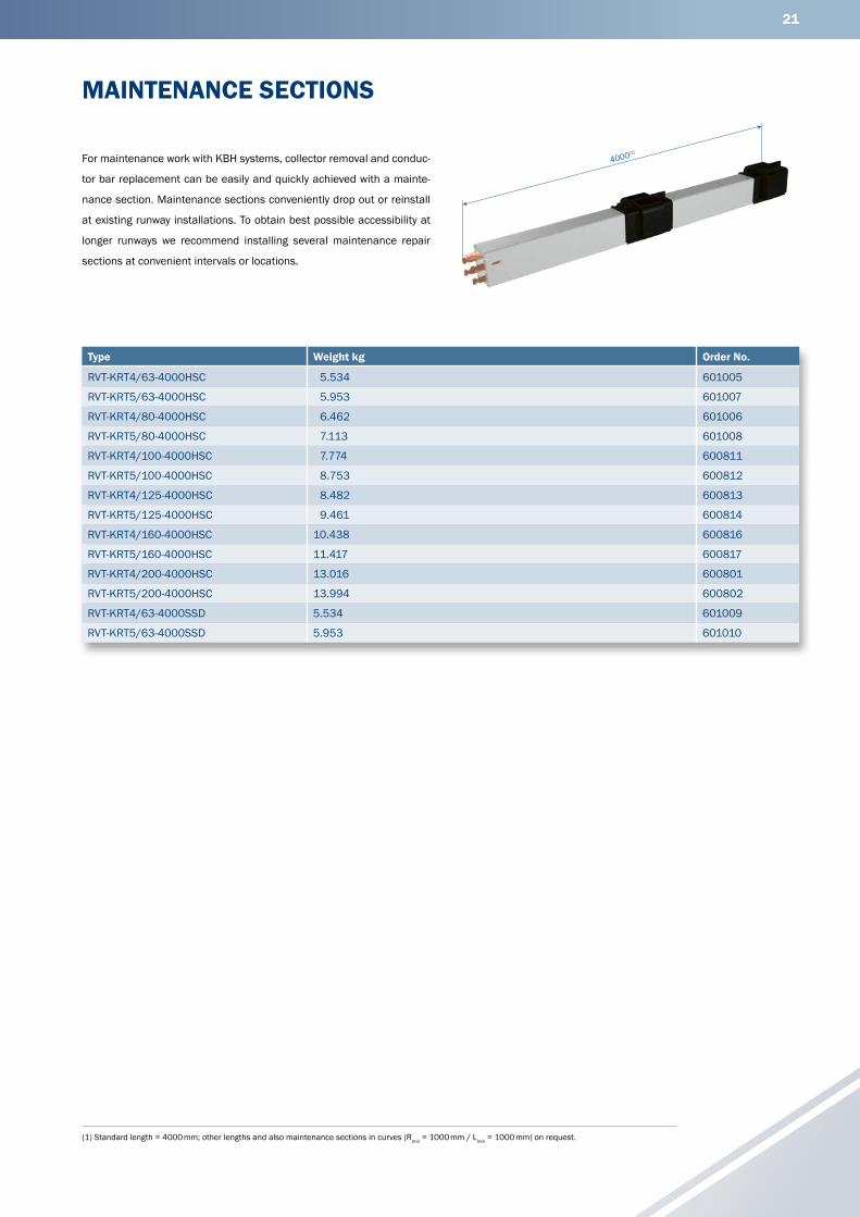
MAINTENANCE SECTIONS
For maintenance work with KBH systems, collector removal and conduc-
tor bar replacement can be easily and quickly achieved with a mainte-
nance section. Maintenance sections conveniently drop out or reinstall
at existing runway installations. To obtain best possible accessibility at
longer runways we recommend installing several maintenance repair
sections at convenient intervals or locations.
Type Weight kg Order No.
RVT-KRT4/63-4000HSC 5.534 601005
RVT-KRT5/63-4000HSC 5.953 601007
RVT-KRT4/80-4000HSC 6.462 601006
RVT-KRT5/80-4000HSC 7.113 601008
RVT-KRT4/100-4000HSC 7.774 600811
RVT-KRT5/100-4000HSC 8.753 600812
RVT-KRT4/125-4000HSC 8.482 600813
RVT-KRT5/125-4000HSC 9.461 600814
RVT-KRT4/160-4000HSC 10.438 600816
RVT-KRT5/160-4000HSC 11.417 600817
RVT-KRT4/200-4000HSC 13.016 600801
RVT-KRT5/200-4000HSC 13.994 600802
RVT-KRT4/63-4000SSD 5.534 601009
RVT-KRT5/63-4000SSD 5.953 601010
4000(1)

22
(1) Also suitable for former 40 A-version
ANTI-CONDENSATION SECTION
Type Weight kg Order No.
BT-KBT4/63-125HSC-1000(1) 3.573 600185
BT-KBT4/160HSC-1000 3.843 600186
BT-KBT4/200HSC-1000 4.358 600319
BT-KBT5/63-125HSC-1000(1) 3.805 600188
BT-KBT5/160HSC-1000 4.075 600189
BT-KBT5/200HSC-1000 4.590 600320
BT-KBT4/63SSD-1000(1) 3.573 600187
BT-KBT5/63SSD-1000(1) 3.805 600190
ANTI-CONDENSATION SECTIONwith special bolted joints for KBHF and KBHS at both ends.
APPLICATION OF ANTI-CONDENSATION SECTIONThe anti-condensation section will be used where conductor systems
are passing from indoor to outdoor, preventing condensation of the out-
side mounted conductor section. The warm air from indoors can escape
through the anti condensation section (see sketch). The anti-condensa-
tion section does not interrupt the conductor system electrically.
Additional feeds are not required.
ASSEMBLYThe anti-condensation section is to be placed directly (0.5 m – 1 m max.)
at the transfer point from indoor to outdoor (see sketch).
1000
X
max. 125 mmax. 125 m
0,5–1 m 0,5–1 m
End capAnti-condensationsection Line feed
Conductorsystem
Fixpoint hanger
OutdoorIndoorOutdoor
Crane runway
23
(1) Also suitable for former 40 A-version
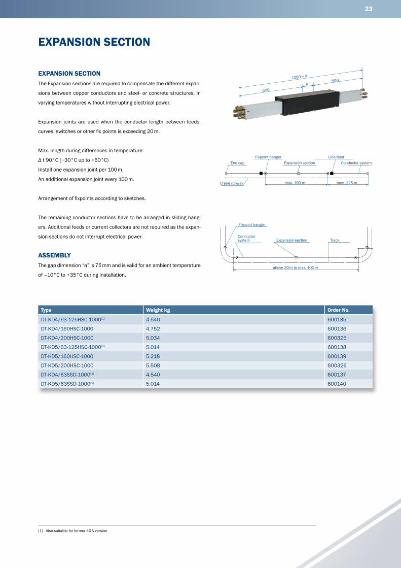
EXPANSION SECTION
Type Weight kg Order No.
DT-KD4/63-125HSC-1000(1) 4.540 600135
DT-KD4/160HSC-1000 4.752 600136
DT-KD4/200HSC-1000 5.034 600325
DT-KD5/63-125HSC-1000(1) 5.014 600138
DT-KD5/160HSC-1000 5.218 600139
DT-KD5/200HSC-1000 5.508 600326
DT-KD4/63SSD-1000(1) 4.540 600137
DT-KD5/63SSD-1000(1) 5.014 600140
EXPANSION SECTIONThe Expansion sections are required to compensate the different expan-
sions between copper conductors and steel- or concrete structures, in
varying temperatures without interrupting electrical power.
Expansion joints are used when the conductor length between feeds,
curves, switches or other fix points is exceeding 20 m.
Max. length during differences in temperature:
Δ t 90°C (−30°C up to +60°C)
Install one expansion joint per 100 m.
An additional expansion joint every 100 m.
Arrangement of fixpoints according to sketches.
The remaining conductor sections have to be arranged in sliding hang-
ers. Additional feeds or current collectors are not required as the expan-
sion-sections do not interrupt electrical power.
ASSEMBLYThe gap dimension “a” is 75 mm and is valid for an ambient temperature
of –10°C to +35°C during installation.
500
5001000 + a
a
X X
max. 100 m max. 125 m
End capFixpoint hanger
Expansion sectionLine feed
Conductor system
Crane runway
X
X
X
XFixpoint hanger
Conductorsystem
above 20 m to max. 100 m
Expansion section Track
24
(1) At 40 % DC
SINGLE CURRENT COLLECTOR
Type Weight kg Number of poles
Power rating at 60 % DC in A
Approx. diameter of connecting -cables in mm
Order No.
SA-KSW4/25-1HS28-60 0.552 4 25 13.0 600095
SA-KSW4/40-1HS28-60 0.656 4 40 15.0 600096
SA-KSW4/60-1HS28-40 0.797 4 60(1) 17.0 600066
SA-KSW5/25-1HS28-60 0.634 5 25 14.0 600098
SA-KSW5/40-1HS28-60 0.771 5 40 17.0 600099
SA-KSW5/60-1HS28-40 0.945 5 60(1) 19.0 600413
SA-KSW4/25-1SS28-60 0.472 4 25 11.0 600097
SA-KSW5/25-1SS28-60 0.534 5 25 12.0 600100
Type Weight kg Number of poles
Power rating at 60 % DC in A
Approx. diameter of connecting- cables in mm
Order No.
SA-KSWS4/25-1HS28-60 0.664 4 25 13.0 600145
SA-KSWS4/40-1HS28-60 0.768 4 40 15.0 600146
SA-KSWS4/60-1HS28-40 0.942 4 60(1) 17.0 600416
SA-KSWS5/25-1HS28-60 0.724 5 25 13.5 600148
SA-KSWS5/40-1HS28-60 0.861 5 40 16.0 600149
SA-KSWS5/60-1HS28-40 1.035 5 60(1) 19.0 600417
SA-KSWS4/25-1SS28-60 0.584 4 25 11.0 600147
SA-KSWS5/25-1SS28-60 0.624 5 25 12.0 600150
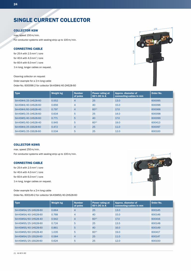
COLLECTOR KSWmax. speed 150 m/min.
For conductor systems with sealing strip up to 100 m/min.
CONNECTING CABLEfor 25 A with 2.5 mm2 / core
for 40 A with 4.0 mm2 / core
for 60 A with 6.0 mm2 / core
1 m long, longer cables on request.
Cleaning collector on request
Order example for a 2 m long cable
Order-No. 600096-2 for collector SA-KSW4/40-2HS28-60
COLLECTOR KSWSmax. speed 250 m/min.
For conductor systems with sealing strip up to 100 m/min.
CONNECTING CABLEfor 25 A with 2.5 mm2 / core
for 40 A with 4.0 mm2 / core
for 60 A with 6.0 mm2 / core
1 m long, longer cables on request.
Order example for a 2 m long cable
Order-No. 600149-2 for collector SA-KSWS5/40-2HS28-60
170
119
272
119
25
(1) At 40 % DC(2) For assembly use enclosed adapter plate(3) Stainless steel
DOUBLE COLLECTOR & TOW ARMS
Type Weight kg Number of poles
Power rating at 60 % DC in A
Approx. diameter of connecting -cables in mm
Order No.
SA-DKSW-4/50-1HS28-60 1.215 4 50 12.5 600115
SA-DKSW4/80-1HS28-60 1.423 4 80 14.5 600116
SA-DKSW4/120-1HS28-40 1.705 4 120(1) 17.0 600414
SA-DKSW5/50-1HS28-60 1.379 5 50 13.5 600118
SA-DKSW5/80-1HS28-60 1.653 5 80 16.0 600119
SA-DKSW5/120-1HS28-40 2.001 5 120(1) 19.0 600415
SA-DKSW4/50-1SS28-60 1.055 4 50 11.0 600117
SA-DKSW5/50-1SS28-60 1.179 5 50 12.0 600120
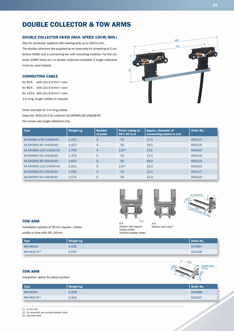
DOUBLE COLLECTOR DKSW (MAX. SPEED 150 M/MIN.)Also for conductor systems with sealing strip up to 100 m/min.
The double collectors are supplied as an assembly kit consisting of 2 col-
lectors (KSW) and a connecting bar with mounting material. For the col-
lector KSWS there are no double collectors available 2 single collectors
must be used instead.
CONNECTING CABLEfor 50 A with (2x) 2.5 mm2 / core
for 80 A with (2x) 4.0 mm2 / core
for 120 A with (2x) 6.0 mm2 / core
1 m long, longer cables on request.
Order example for 2 m long cables
Order-No. 600119-2 for collector SA-DKSW5/80-2HS28-60
For curves use single collectors only.
Type Weight kg Order No.
MN-MGUN 0.436 600887
MN-MGU/K(3) 0.550 600336
Type Weight kg Order No.
MN-MGFN 0.328 600888
MN-MGF/K(3) 0.442 600337
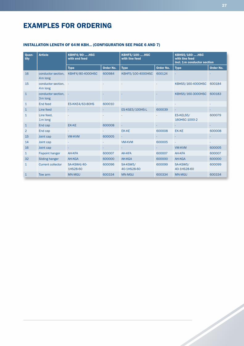
TOW ARMInstallation options of 30 mm square-, hollow
profile or tube with 30–34 mm
TOW ARMInstallation option for plane surface
190
53100A Aby customer
234 to center of tube
480
310
121
M 8
252
50±1
0
60
8553100
190
Slotted hole9 x 18
A-AVersion with square hollow profile(without adapter plate)
A-AVersion with tube (2)

26
(1) To be fixed during installation.
FLEXIBLE TOW ARM
FLEXIBLE TOW ARMFlexible support type for single collector for installations with transfer fun-
nels type KET (see page 17). Measurements for installation see below.
If you are going to use the flexible towing arm in system with curves
please contact us.
Type Weight kg Order No.
MN-KFMHN 1.067 600558
ARRANGEMENT OF A FLEXIBLE TOW ARMKFMHN with collector type KSW
max. horizontal offset 10 mm
max. vertical offset 10 mm
330
90
138
Slotted hole 9 x 18
A
30
A
186
990
668
70
54
Ø 10
6,3
ca. 6
0 (1
)
L2L1
Fixi
ng s
ide
330
305
138
27
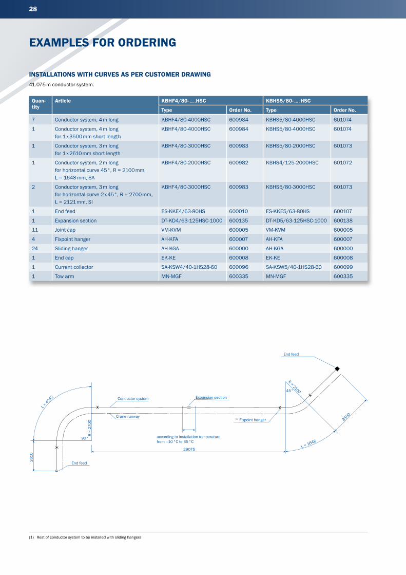
EXAMPLES FOR ORDERING
INSTALLATION LENGTH OF 64 M KBH... (CONFIGURATION SEE PAGE 6 AND 7)
Quan-tity
Article KBHF4/80- ... .HSCwith end feed
KBHF5/100- ... .HSC with line feed
KBHS5/160- ... .HSC with line feed incl. 1 m conductor section
Type Order No. Type Order No. Type Order No.
16 conductor section, 4 m long
KBHF4/80-4000HSC 600984 KBHF5/100-4000HSC 600124 - -
15 conductor section, 4 m long
- - - - KBHS5/160-4000HSC 600184
1 conductor section, 3 m long
- - - - KBHS5/160-3000HSC 600183
1 End feed ES-KKE4/63-80HS 600010 - - - -
1 Line feed - - ES-KSE5/100HS-L 600039 - -
1 Line feed,1 m long
- - - - ES-KELS5/ 160HSC-1000-2
600079
1 End cap EK-KE 600008 - - - -
2 End cap - - EK-KE 600008 EK-KE 600008
15 Joint cap VM-KVM 600005 - - - -
14 Joint cap - - VM-KVM 600005 - -
16 Joint cap - - - - VM-KVM 600005
1 Fixpoint hanger AH-KFA 600007 AH-KFA 600007 AH-KFA 600007
32 Sliding hanger AH-KGA 600000 AH-KGA 600000 AH-KGA 600000
1 Current collector SA-KSW4/40-1HS28-60
600096 SA-KSW5/ 40-1HS28-60
600099 SA-KSW5/ 40-1HS28-60
600099
1 Tow arm MN-MGU 600334 MN-MGU 600334 MN-MGU 600334
28
(1) Rest of conductor system to be installed with sliding hangers
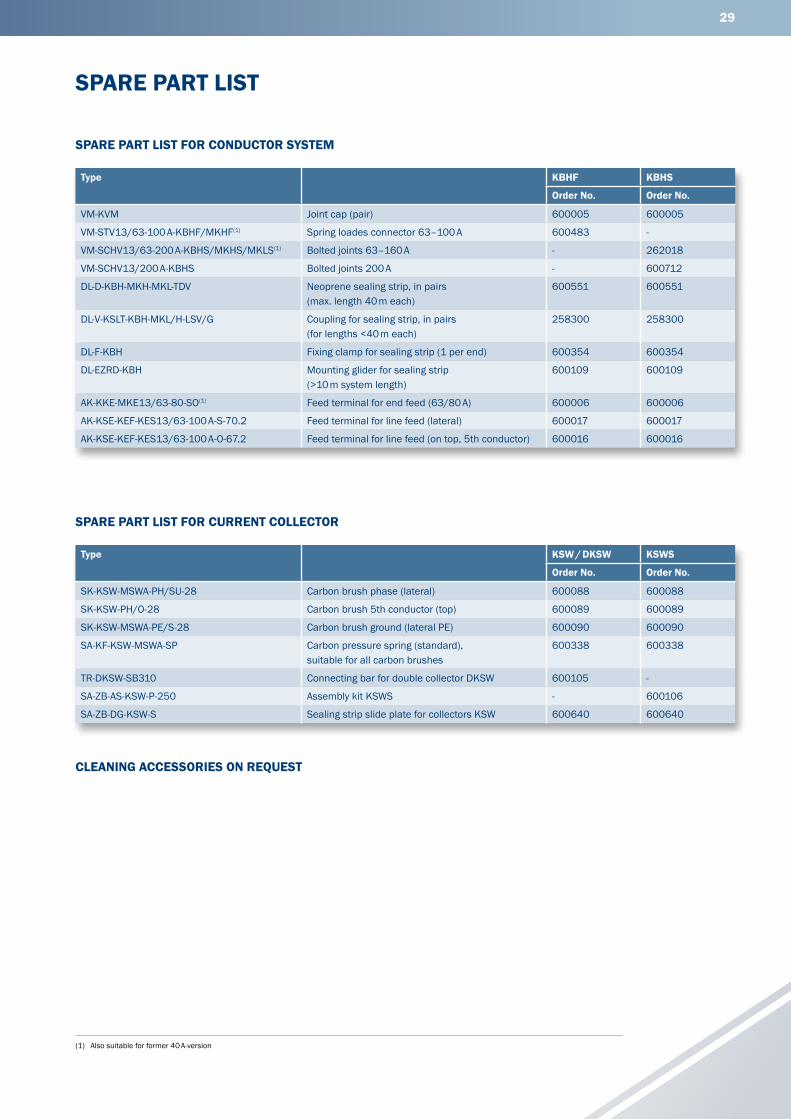
EXAMPLES FOR ORDERING
41.075 m conductor system.
Quan-tity
Article KBHF4/80- ... .HSC KBHS5/80- ... .HSC
Type Order No. Type Order No.
7 Conductor system, 4 m long KBHF4/80-4000HSC 600984 KBHS5/80-4000HSC 601074
1 Conductor system, 4 m long for 1 x 3500 mm short length
KBHF4/80-4000HSC 600984 KBHS5/80-4000HSC 601074
1 Conductor system, 3 m long for 1 x 2610 mm short length
KBHF4/80-3000HSC 600983 KBHS5/80-2000HSC 601073
1 Conductor system, 2 m long for horizontal curve 45°, R = 2100 mm, L = 1648 mm, SA
KBHF4/80-2000HSC 600982 KBHS4/125-2000HSC 601072
2 Conductor system, 3 m long for horizontal curve 2 x 45°, R = 2700 mm, L = 2121 mm, SI
KBHF4/80-3000HSC 600983 KBHS5/80-3000HSC 601073
1 End feed ES-KKE4/63-80HS 600010 ES-KKE5/63-80HS 600107
1 Expansion section DT-KD4/63-125HSC-1000 600135 DT-KD5/63-125HSC-1000 600138
11 Joint cap VM-KVM 600005 VM-KVM 600005
4 Fixpoint hanger AH-KFA 600007 AH-KFA 600007
24 Sliding hanger AH-KGA 600000 AH-KGA 600000
1 End cap EK-KE 600008 EK-KE 600008
1 Current collector SA-KSW4/40-1HS28-60 600096 SA-KSW5/40-1HS28-60 600099
1 Tow arm MN-MGF 600335 MN-MGF 600335
INSTALLATIONS WITH CURVES AS PER CUSTOMER DRAWING
3500
L = 1648
29075
L = 4242
R =
2700
90°
R = 210045°
2610
End feed
Crane runway
Conductor system Expansion section
according to installation temperaturefrom –10 °C to 35 °C
(1) Fixpoint hanger
End feed
29
(1) Also suitable for former 40 A-version
SPARE PART LIST
SPARE PART LIST FOR CURRENT COLLECTOR
Type KSW / DKSW KSWS
Order No. Order No.
SK-KSW-MSWA-PH/SU-28 Carbon brush phase (lateral) 600088 600088
SK-KSW-PH/O-28 Carbon brush 5th conductor (top) 600089 600089
SK-KSW-MSWA-PE/S-28 Carbon brush ground (lateral PE) 600090 600090
SA-KF-KSW-MSWA-SP Carbon pressure spring (standard), suitable for all carbon brushes
600338 600338
TR-DKSW-SB310 Connecting bar for double collector DKSW 600105 -
SA-ZB-AS-KSW-P-250 Assembly kit KSWS - 600106
SA-ZB-DG-KSW-S Sealing strip slide plate for collectors KSW 600640 600640
SPARE PART LIST FOR CONDUCTOR SYSTEM
Type KBHF KBHS
Order No. Order No.
VM-KVM Joint cap (pair) 600005 600005
VM-STV13/63-100 A-KBHF/MKHF(1) Spring loades connector 63–100 A 600483 -
VM-SCHV13/63-200 A-KBHS/MKHS/MKLS(1) Bolted joints 63–160 A - 262018
VM-SCHV13/200 A-KBHS Bolted joints 200 A - 600712
DL-D-KBH-MKH-MKL-TDV Neoprene sealing strip, in pairs (max. length 40 m each)
600551 600551
DL-V-KSLT-KBH-MKL/H-LSV/G Coupling for sealing strip, in pairs (for lengths <40 m each)
258300 258300
DL-F-KBH Fixing clamp for sealing strip (1 per end) 600354 600354
DL-EZRD-KBH Mounting glider for sealing strip (>10 m system length)
600109 600109
AK-KKE-MKE13/63-80-SO(1) Feed terminal for end feed (63/80 A) 600006 600006
AK-KSE-KEF-KES13/63-100 A-S-70.2 Feed terminal for line feed (lateral) 600017 600017
AK-KSE-KEF-KES13/63-100 A-O-67.2 Feed terminal for line feed (on top, 5th conductor) 600016 600016
CLEANING ACCESSORIES ON REQUEST
30
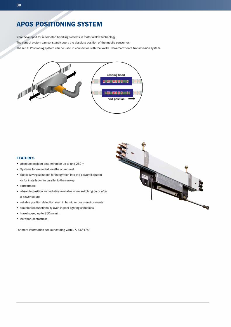
APOS POSITIONING SYSTEM
were developed for automated handling systems in material flow technology.
The control system can constantly query the absolute position of the mobile consumer.
The APOS Positioning system can be used in connection with the VAHLE Powercom® data transmission system.
FEATURES• absolute position determination up to and 262 m
• Systems for exceeded lengths on request
• Space-saving solutions for integration into the powerail system
or for installation in parallel to the runway
• retrofittable
• absolute position immediately available when switching on or after
a power failure
• reliable position detection even in humid or dusty environments
• trouble-free functionality even in poor lighting conditions
• travel speed up to 250 m/min
• no wear (contactless)
For more information see our catalog VAHLE APOS® (7a)
reading head
next position
31
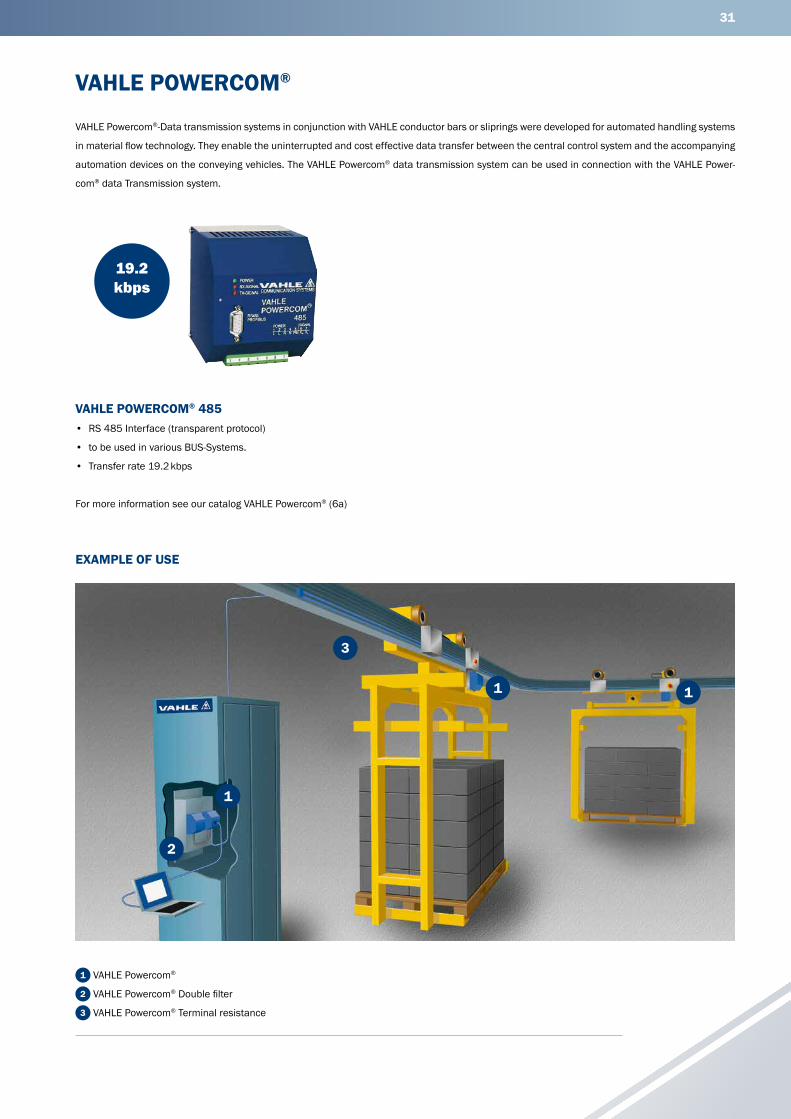
VAHLE POWERCOM®
VAHLE POWERCOM® 485• RS 485 Interface (transparent protocol)
• to be used in various BUS-Systems.
• Transfer rate 19.2 kbps
VAHLE Powercom®-Data transmission systems in conjunction with VAHLE conductor bars or sliprings were developed for automated handling systems
in material flow technology. They enable the uninterrupted and cost effective data transfer between the central control system and the accompanying
automation devices on the conveying vehicles. The VAHLE Powercom® data transmission system can be used in connection with the VAHLE Power-
com® data Transmission system.
19.2 kbps
For more information see our catalog VAHLE Powercom® (6a)
1 VAHLE Powercom®
2 VAHLE Powercom® Double filter
3 VAHLE Powercom® Terminal resistance
EXAMPLE OF USE
1
1
2
3
1

32
(1) For curved tracks, powerail with isolating sections etc., we require sketches to enable us to prepare a quotation(2) Use: K for squirrel cage motor, S for slipring motor, F for frequency controlled motor We reserve all rights to make alterations in the interests of further development Please copy and fill in the questionnaire.
QUESTIONNAIRECompany: ___________________________________________________ Date: _______________________________________________________
Fon: ________________________________________________________ Fax: ________________________________________________________
E-mail: ______________________________________________________ Internet: _____________________________________________________
1. Number of conductor system installations: ____________________________________________________________________________________
2. Type of equipment to be powered: ____________________________________________________________________________________________
3. Operating voltage: ________ Volt Frequency: ________ Hz
Three-phase voltage AC voltage DC voltage
4. Track length: _____________________________________________________________________________________________________________
5. Number of conductors: ________ neutral: ________ control: ________ ground: ________
6. Mounted position of conductor system:
Conductor system pendant, collector cable facing to the bottom Conductor system pendant, lateral payout of conductor cable(1)
Support distance ________ m (max. 2 m) Other: __________________________________________________________________________
7. Number of consumers per system: ___________________________________________________________________________________________
8. Indoor system Outdoor system
9. Other operating conditions (humidity, dust, chemical influence, etc.) _______________________________________________________________
10. Ambient temperature: ________°C min. ________°C max.
11. Hall expansion joints ________ pieces ________ expansion max.
12. Position and number of feeding points(1): ______________________________________________________________________________________
13. Position and number of isolating sections (e. g. for maintenance)(1): ________________________________________________________________
14. How will the conductor be arranged?(1): _______________________________________________________________________________________
15. Brackets required: Yes No c/c distance beam/conductor system: ________________________________________________________
16. Travel speed: ________ m/min. in curves: ________ m/min. at transfers: ________ m/min.
17. Max. voltage drop from the conductor system feed point to the consumer considering starting current. ___________________________________
18. Power consumption of the individual consumer loads: ___________________________________________________________________________
Motor dataCrane 1 Crane 2
Power kW
Nominal current Starting current
Type of motors (2)
Power kW
Nominal current Starting current
Type of motors (2)
A cos ϕN % duty A cos ϕA A cos ϕN % duty A cos ϕA
Hoist motors
Auxiliary hoist
Long travel
Cross travel
Mark with * those motors which can run simultaneously.
Mark with Δ those motors which can start up simultaneously.
Further remarks: _____________________________________________________________________________________________________________
____________________________________________________________________________________________________________________________
Signature:
33
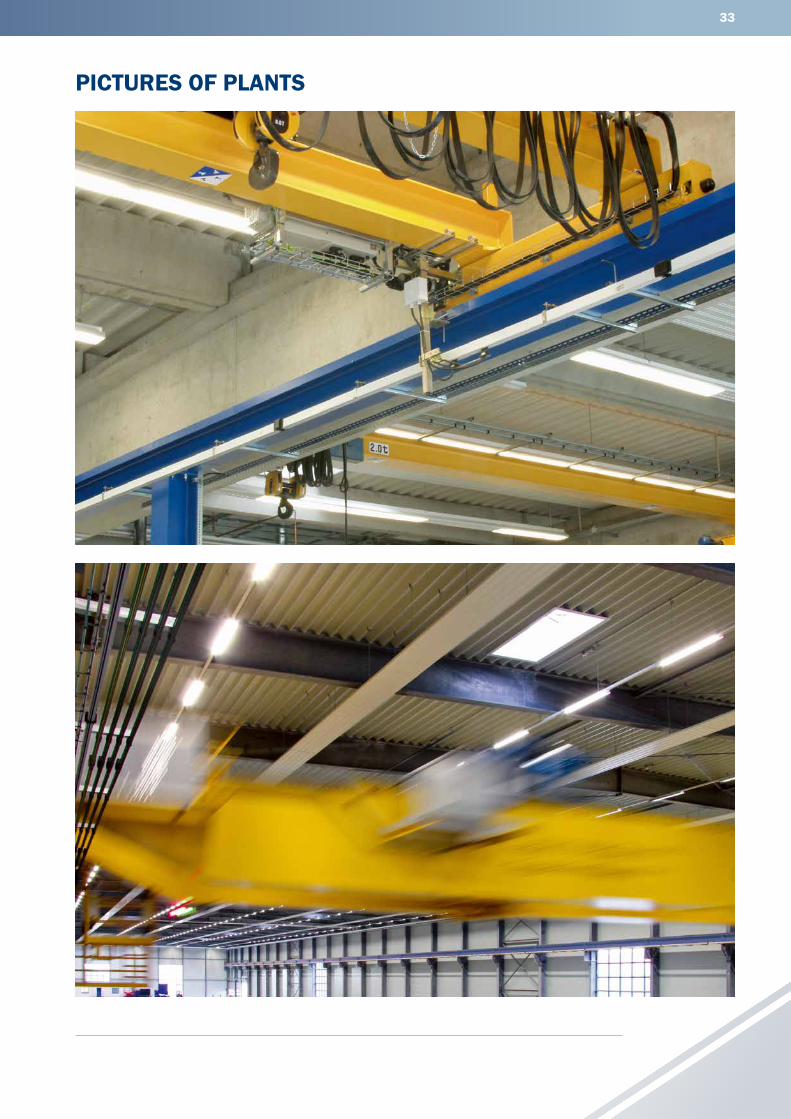
PICTURES OF PLANTS

34
NOTES

35
NOTES
Paul Vahle GmbH & Co. KGWesticker Str. 52
59174 KamenGermany
Tel.: +49 2307 704-0Fax: +49 2307 704-444
www.vahle.com
W25
0764
0/00
/en
| 0
| Re
v.02
| 0
1/19
| E
rrors
and
tech
nica
l mod
ifica
tions
sub
ject
to c
hang
e.