Encapsulator B-390/B-395 Pro Laboratory Guide · PDF file1 Introduction This laboratory guide...
60
Encapsulator B-390/B-395 Pro Laboratory Guide
-
Upload
hoangthuan -
Category
Documents
-
view
216 -
download
3
Transcript of Encapsulator B-390/B-395 Pro Laboratory Guide · PDF file1 Introduction This laboratory guide...

Encapsulator B-390/B-395 ProLaboratory Guide

Contents
Part A: Encapsulation Prilling by Vibration . . . . . . . . . . . . . . . . . . . . . . . . . . . . . . . . . . . . . . . . . . . . . . . . 3
1 Introduction . . . . . . . . . . . . . . . . . . . . . . . . . . . . . . . . . . . . . . . . . . . . . . . . . . . . . . . . . . . . . . . . . . . . . 3
1.1 What is Encapsulation? 3
1.2 Reasons for encapsulating a material 4
1.3 BUCHI Encapsulators B-390 and B-395 Pro 5
2 Operation of the BUCHI Encapsulators: Prilling by Vibration technique . . . . . . . . . . . . . . . . . . 8
2.1 Operational principle of the BUCHI Encapsulators 8
2.3 Nozzle configurations 10
2.4 Production of beads – Single Nozzle 10
2.5 Production of capsules – Concentric Nozzle 11
2.6 Production of small beads - Flow Vibration Nozzle 13
2.7 Encapsulation of cell clusters – Air Dripping Nozzle 13
2.8 Summary of nozzle configurations 15
3 Process Parameters for Optimized Production . . . . . . . . . . . . . . . . . . . . . . . . . . . . . . . . . . . . . 16
3.1 Process parameters influencing production 16
3.2 Rules for producing beads/capsules 16
3.3 Rules for bead production only 16
3.4 Rules for capsule production only 16
4 Structural differences between the Encapsulator B-390 and B-395 Pro . . . . . . . . . . . . . . . 18
4.1 Temperature dependent polymer solutions . . . . . . . . . . . . . . . . . . . . . . . . . . . . . . . . . . . . . . . . . . . . . 18
4.2 Sterile production and applications 18
4.3 High precision delivery of polymer/liquids 20
5 Quick-start guide for the Single Nozzle system . . . . . . . . . . . . . . . . . . . . . . . . . . . . . . . . . . . . . 21
5.1 Template for recording process parameters and results 24
5.2 Characteristics of the beads/capsules produced using the BUCHI Encapsulators B-390 and B-395 Pro
and the characteristics of the production technique 25
6 Large Scale Production . . . . . . . . . . . . . . . . . . . . . . . . . . . . . . . . . . . . . . . . . . . . . . . . . . . . . . . . .26
7 Operational trouble-shooting . . . . . . . . . . . . . . . . . . . . . . . . . . . . . . . . . . . . . . . . . . . . . . . . . . . . . 27
8 References . . . . . . . . . . . . . . . . . . . . . . . . . . . . . . . . . . . . . . . . . . . . . . . . . . . . . . . . . . . . . . . . . . . .29
Part B: Application Notes . . . . . . . . . . . . . . . . . . . . . . . . . . . . . . . . . . . . . . . . . . . . . . . . . . . . . . . . . . . . .30
9.1 Production of Ca-alginate beads 31
9.2 Production of core-shell capsules 35
9.3 Encapsulation of hydrophobic liquids within microbeads 39
9.4 Production of hard fat capsules 42
9.5 Producing large Ca-alginate microbeads 45
9.6 Producing cellulose sulphate microcapsules 47
9.7 Encapsulation within gelatin beads 50
9.8 Encapsulation of probiotics in whey protein beads 53
9.9 Encapsulation of Methotrexate in alginate and hyaluronic acid microcapsules for controlled release in
cancer treatment 55

1 Introduction
This laboratory guide gives an overview of encapsulation using the Prilling by Vi-
bration technique and how it can be performed using the BUCHI Encapsulators
B-390 and B-395 Pro.
1 .1 What is Encapsulation?
Encapsulation can be defined as a process which involves the complete envelop-
ment of pre-selected materials (solid, liquid and gases) within a porous or imper-
meable matrix and/or membrane using various techniques, to give miniature sized
particles ranging from a few hundred nano-meters up to a several millimeters in
size [1]. In general particles < 1 μm in size are called nano, 1-2000 μm are termed
micro and > 2000 μm are referred to as macro – beads/capsules. Structurally the
produced particles can be classified as either beads or capsules (also referred to
as core-shell capsule) [2].
Beads: Spherical particles having the encapsulated material distributed through-
out matrix structure i.e. has no distinctive core and shell part [Fig. 1(a)].
Capsules: Spherical particles consisting of a defined core (containing the encap-
sulated material) completely surrounded by a shell (membrane) structure [Fig 1(b)].
Encapsulated material distributed throughout matrix membrane
(a) (b)
Encapsulated material within defined core
Shell-membrane
Figure 1: Images displaying the structural differences between (a) beads and (b) core-shell capsules.
Part A: Encapsulation Prilling by Vibration
1 .2 Reasons for encapsulating a material
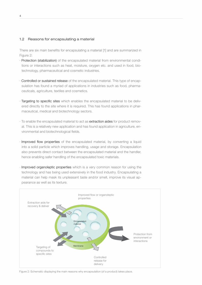
There are six main benefits for encapsulating a material [1] and are summarized in
Figure 2:
∙ Protection (stabilization) of the encapsulated material from environmental condi-
tions or interactions such as heat, moisture, oxygen etc. and used in food, bio-
technology, pharmaceutical and cosmetic industries.
∙ Controlled or sustained release of the encapsulated material. This type of encap-
sulation has found a myriad of applications in industries such as food, pharma-
ceuticals, agriculture, textiles and cosmetics.
∙ Targeting to specific sites which enables the encapsulated material to be deliv-
ered directly to the site where it is required. This has found applications in phar-
maceutical, medical and biotechnology sectors.
∙ To enable the encapsulated material to act as extraction aides for product remov-
al. This is a relatively new application and has found application in agriculture, en-
vironmental and biotechnological fields.
∙ Improved flow properties of the encapsulated material, by converting a liquid
into a solid particle which improves handling, usage and storage. Encapsulation
also prevents direct contact between the encapsulated material and the handler,
hence enabling safer handling of the encapsulated toxic materials.
∙ Improved organoleptic properties which is a very common reason for using the
technology and has being used extensively in the food industry. Encapsulating a
material can help mask its unpleasant taste and/or smell, improve its visual ap-
pearance as well as its texture.
4
Extraction aids for recovery & deliver
Targeting of compounds to specific sites
Controlled release for delivery
Protection from environment or interactions
Encapsulated material
Improved flow or organoleptic properties
Membrane
Figure 2: Schematic displaying the main reasons why encapsulation (of a product) takes place.
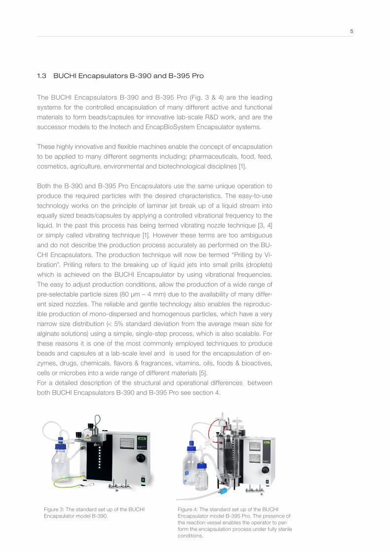
1 .3 BUCHI Encapsulators B-390 and B-395 Pro
The BUCHI Encapsulators B-390 and B-395 Pro (Fig. 3 & 4) are the leading
systems for the controlled encapsulation of many different active and functional
materials to form beads/capsules for innovative lab-scale R&D work, and are the
successor models to the Inotech and EncapBioSystem Encapsulator systems.
These highly innovative and flexible machines enable the concept of encapsulation
to be applied to many different segments including; pharmaceuticals, food, feed,
cosmetics, agriculture, environmental and biotechnological disciplines [1].
Both the B-390 and B-395 Pro Encapsulators use the same unique operation to
produce the required particles with the desired characteristics. The easy-to-use
technology works on the principle of laminar jet break up of a liquid stream into
equally sized beads/capsules by applying a controlled vibrational frequency to the
liquid. In the past this process has being termed vibrating nozzle technique [3, 4]
or simply called vibrating technique [1]. However these terms are too ambiguous
and do not describe the production process accurately as performed on the BU-
CHI Encapsulators. The production technique will now be termed “Prilling by Vi-
bration”. Prilling refers to the breaking up of liquid jets into small prills (droplets)
which is achieved on the BUCHI Encapsulator by using vibrational frequencies.
The easy to adjust production conditions, allow the production of a wide range of
pre-selectable particle sizes (80 µm – 4 mm) due to the availability of many differ-
ent sized nozzles. The reliable and gentle technology also enables the reproduc-
ible production of mono-dispersed and homogenous particles, which have a very
narrow size distribution (< 5% standard deviation from the average mean size for
alginate solutions) using a simple, single-step process, which is also scalable. For
these reasons it is one of the most commonly employed techniques to produce
beads and capsules at a lab-scale level and is used for the encapsulation of en-
zymes, drugs, chemicals, flavors & fragrances, vitamins, oils, foods & bioactives,
cells or microbes into a wide range of different materials [5].
For a detailed description of the structural and operational differences between
both BUCHI Encapsulators B-390 and B-395 Pro see section 4.
Figure 3: The standard set up of the BUCHI Encapsulator model B-390.
Figure 4: The standard set up of the BUCHI Encapsulator model B-395 Pro. The presence of the reaction vessel enables the operator to per-form the encapsulation process under fully sterile conditions.
5
6
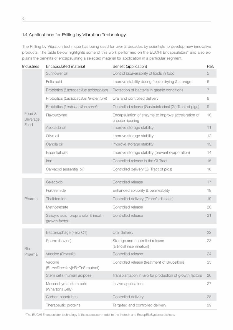
1 .4 Applications for Prilling by Vibration Technology
The Prilling by Vibration technique has being used for over 2 decades by scientists to develop new innovative
products. The table below highlights some of this work performed on the BUCHI Encapsulators* and also ex-
plains the benefits of encapsulating a selected material for application in a particular segment.
Industries Encapsulated material Benefit (application) Ref.
Food &Beverage,Feed
Sunflower oil Control bioavailability of lipids in food 5
Folic acid Improve stability during freeze drying & storage 6
Probiotics (Lactobacillus acidophilus) Protection of bacteria in gastric conditions 7
Probiotics (Lactobacillus fermentum) Oral and controlled delivery 8
Probiotics (Lactobacillus casei) Controlled release (Gastrointesinal (GI) Tract of pigs) 9
Flavourzyme Encapsulation of enzyme to improve acceleration of cheese ripening
10
Avocado oil Improve storage stability 11
Olive oil Improve storage stability 12
Canola oil Improve storage stability 13
Essential oils Improve storage stability (prevent evaporation) 14
Iron Controlled release in the GI Tract 15
Carvacrol (essential oil) Controlled delivery (GI Tract of pigs) 16
Pharma
Celecoxib Controlled release 17
Furosemide Enhanced solubility & permeability 18
Thalidomide Controlled delivery (Crohn’s disease) 19
Methotrexate Controlled release 20
Salicylic acid, propranolol & insulin growth factor I
Controlled release 21
Bio-Pharma
Bacteriophage (Felix O1) Oral delivery 22
Sperm (bovine) Storage and controlled release (artificial insemination)
23
Vaccine (Brucella) Controlled release 24
Vaccine(B. melitensis vjbR::Tn5 mutant)
Controlled release (treatment of Brucellosis) 25
Stem cells (human adipose) Transplantation in vivo for production of growth factors 26
Mesenchymal stem cells (Whartons Jelly)
In vivo applications 27
Carbon nanotubes Controlled delivery 28
Therapeutic proteins Targeted and controlled delivery 29
*The BUCHI Encapsulator technology is the successor model to the Inotech and EncapBioSystems devices.
7
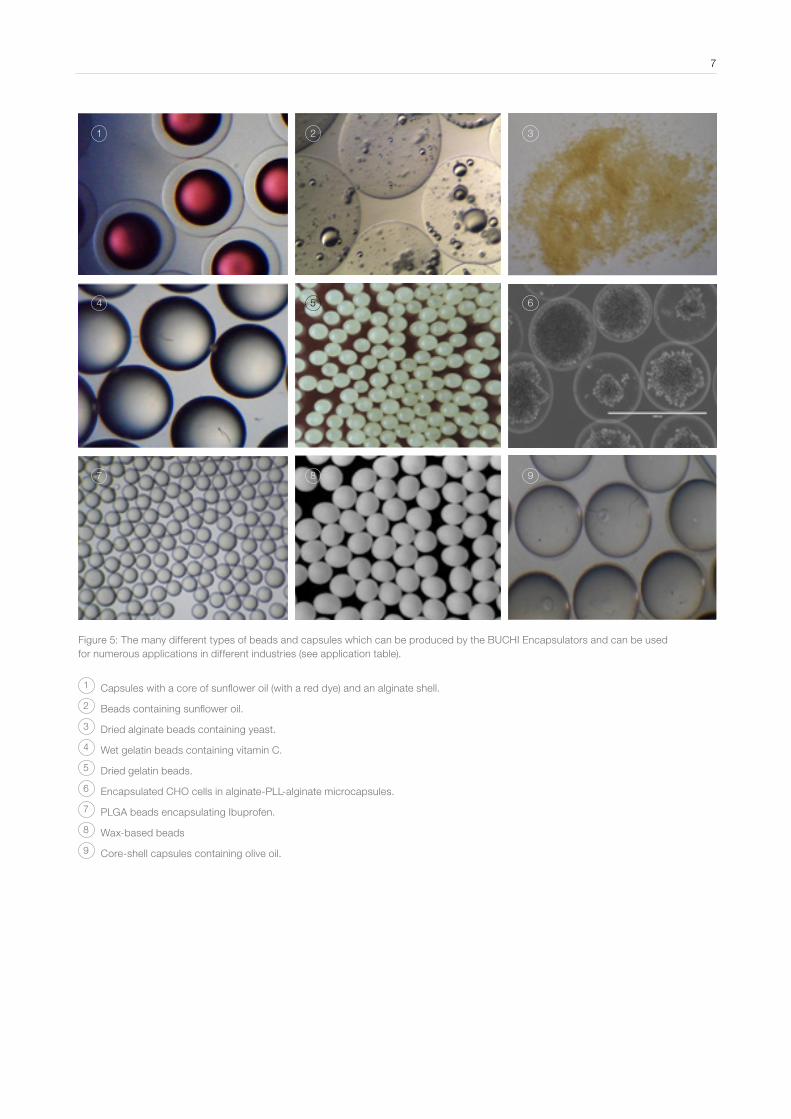
Figure 5: The many different types of beads and capsules which can be produced by the BUCHI Encapsulators and can be used for numerous applications in different industries (see application table).
1 Capsules with a core of sunflower oil (with a red dye) and an alginate shell.
2 Beads containing sunflower oil.
3 Dried alginate beads containing yeast.
4 Wet gelatin beads containing vitamin C.
5 Dried gelatin beads.
6 Encapsulated CHO cells in alginate-PLL-alginate microcapsules.
7 PLGA beads encapsulating Ibuprofen.
8 Wax-based beads
9 Core-shell capsules containing olive oil.
1
4
7
2
5
8
3
6
9

2 Operation of the BUCHI Encapsulators: Prilling by Vibration technique
2 .1 Operational principle of the BUCHI Encapsulators
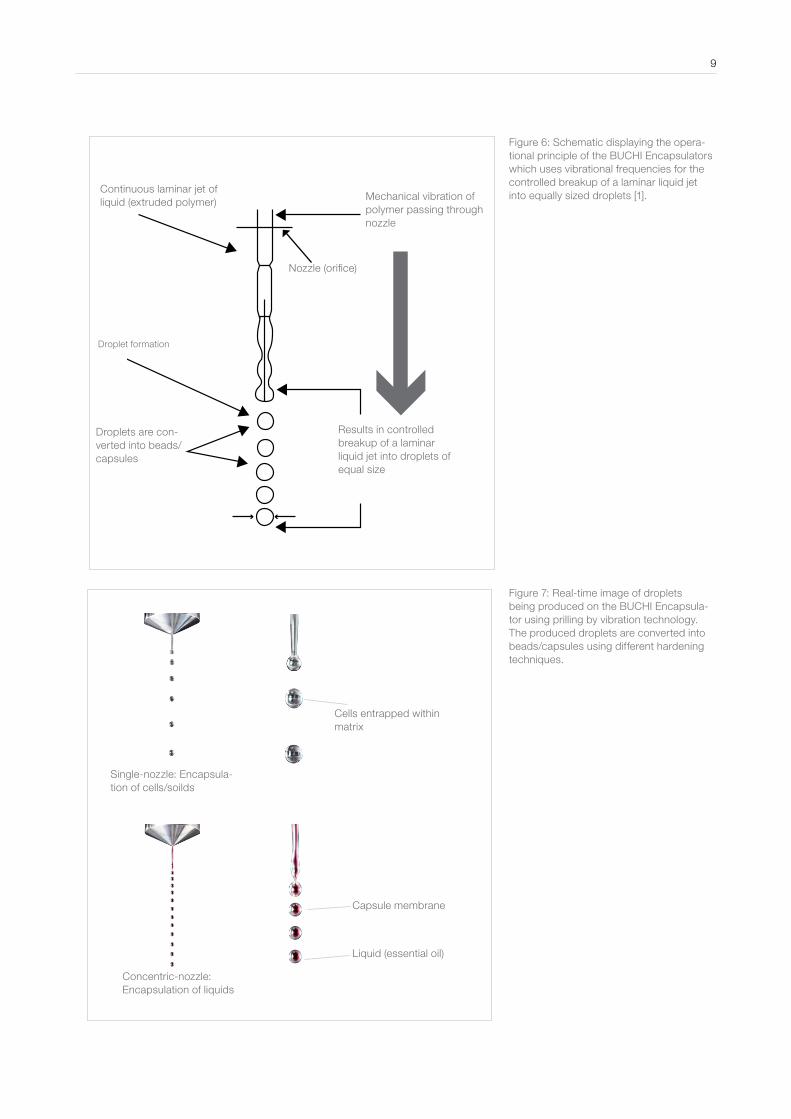
The operation of both BUCHI Encapsulators B-390 and B-395 Pro is based on
the principle of laminar liquid jet breakup into droplets by applying a superimposed
mechanical vibration onto it (Fig. 6 & 7). The extrusion of a polymer liquid (contain-
ing the material to be encapsulated) through a selected nozzle on a BUCHI Encap-
sulator results in the formation of a laminar flow liquid jet. A controlled, superim-
posed vibrational frequency at defined amplitude is then imposed onto this jet and
causes the jet to break-up into small uniform droplets of equal size, with one drop-
let formed per hertz of frequency applied [1, 3, 4]. For the BUCHI Encapsulator this
force is applied by vibrating the polymer liquid in a chamber (bead producing unit)
before it is extruded through the nozzle (Fig. 6). After formation the produced drop-
lets are then converted subsequently into beads or capsules.
To prevent coalescence of the droplets during jet break-up and/or when entering
the gelling bath, an electrical charge is induced onto the surface of the droplets us-
ing an electrostatic voltage system. This system applies an electrical potential be-
tween the nozzle and an electrode, placed directly underneath the nozzle [1, 3, 31].
As droplets fall through the electrode, they are charged and deflected from their
vertical position resulting in their impact occurring over a larger area in the harden-
ing solution. This enables mono-disperse beads and capsules with a standard size
deviation of ≤ 5% to be produced when using alginate solutions.
The size of the produced droplets and the rate of production are mainly dependent
on the nozzle size, the flow rate and viscosity of the extruded liquid, and the vibra-
tional frequency applied. These parameters can all be controlled when using the
BUCHI Encapsulators, enabling the operator to pre-determine the size and char-
acteristics of the beads and capsules that are produced. For a detailed description
on how each variable parameter effects bead and capsule production see Section
3. For more details on the theoretical aspects behind laminar jet break up (Ray-
leigh’s jet instability) using vibrational frequencies see [1, 3].
8
9
Figure 7: Real-time image of droplets being produced on the BUCHI Encapsula-tor using prilling by vibration technology. The produced droplets are converted into beads/capsules using different hardening techniques.
Figure 6: Schematic displaying the opera-tional principle of the BUCHI Encapsulators which uses vibrational frequencies for the controlled breakup of a laminar liquid jet into equally sized droplets [1].
Single-nozzle: Encapsula-tion of cells/soilds
Concentric-nozzle: Encapsulation of liquids
Liquid (essential oil)
Capsule membrane
Cells entrapped within matrix
Droplets are con-verted into beads/capsules
Results in controlled breakup of a laminar liquid jet into droplets of equal size
Droplet formation
Continuous laminar jet of liquid (extruded polymer) Mechanical vibration of
polymer passing through nozzle
Nozzle (orifice)
2 .3 Nozzle configurations
Both BUCHI Encapsulators B-390 and B-395 Pro can work with either one of four
different nozzle configurations. The selected nozzle system depends on the type
of beads and capsules and the size that are required, as well as the material being
encapsulated.
∙ Single nozzle system: Production of beads with a size of 150 µm – 4 mm.
∙ Concentric nozzle system: Production of core-shell capsules in a single-step
process.
∙ Flow vibration nozzle: Production of smaller beads (80 µm) from viscous
solution.
∙ Air Dripping nozzle: Encapsulating cell clusters and islets in beads.
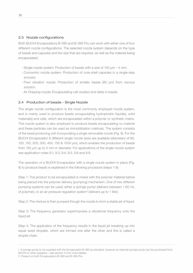
2 .4 Production of beads – Single Nozzle
The single nozzle configuration is the most commonly employed nozzle system,
and is mainly used to produce beads encapsulating hydrophobic liquid(s), solid
material(s) and cells, which are encapsulated within a polymer or synthetic matrix.
This nozzle system is also employed to produce beads encapsulating no material
and these particles can be used as immobilization matrices. The system consists
of the bead producing unit incorporating a single removable nozzle (Fig. 8). For the
BUCHI Encapsulator 8 different single nozzle sizes are available (diameters of 80,
120, 150, 200, 300, 450, 750 & 1000 µm), which enables the production of beads
from 150 µm up to 4 mm in diameter. For applications of the single nozzle system
see application notes 9.1, 9.3, 9.4, 9.5, 9.8 and 9.9.
The operation of a BUCHI Encapsulator with a single nozzle system in place (Fig.
8) to produce beads is explained in the following procedure (steps 1-8).
Step 1: The product to be encapsulated is mixed with the polymer material before
being placed into the polymer delivery (pumping) mechanism. One of two different
pumping systems can be used; either a syringe pumpI (delivers between 1-60 mL
of polymer), or an air pressure regulation systemII (delivers up to 1 liter).
Step 2: The mixture is then pumped though the nozzle to form a stable jet of liquid.
Step 3: The frequency generator superimposes a vibrational frequency onto the
liquid jet.
Step 4: The application of the frequency results in the liquid jet breaking up into
equal sized droplets, which are formed one after the other and this is called a
droplet chain.
10
I A syringe pump is not supplied with the Encapsulator B-390 as standard, however an external syringe pump can be purchased from BUCHI or other suppliers – see section 4.3 for more details.II Present on both Encapsulators B-390 and B-395 Pro.

Step 5: The electrostatic voltage system is turned on and induces an electrical
charge onto the surface of each droplet, causing them to repel each other and dis-
perses them into a cone like shape. This prevents coalescence of droplets from oc-
curring, hence enabling mono-dispersed of equal size and shape to be produced.
Step 6: The liquid jet break up process to form droplets can be viewed and moni-
tored in the light of a stroboscopic lamp, which is placed directly behind the drop-
lets. This enables optimal droplet formation to be obtained before landing in the
gelling bath.
Step 7: Upon landing in the agitated hardening bath the droplets are converted into
beads either by gelation or a polymerization reaction. The encapsulated material is
entrapped within the matrix structure of the beads.
Step 8: After production the produced particles can be removed and used as re-
quired or pre-treated further.
2 .5 Production of capsules – Concentric Nozzle
The concentric nozzle is a standard nozzle configuration to produce core-shell
capsules in a single step process in the laboratory. The system consists of the
concentric nozzle producing unit which holds two nozzles, one termed an inner
or core nozzle (one of the nozzles from the single nozzle system), and the second
termed an external or shell nozzle (Fig. 9 a). For production of capsules the inner
nozzle is placed directly into the shell nozzle and the two nozzles combined are re-
Figure 8: Schematic displaying the operation of the BUCHI Encapsulators B-390/B-395 Pro when using a single nozzle system to produce beads. The numbers 1-8 display the location where each step of the production procedure takes place.
1. Preparing2. Pumping3. Vibration generator4. Droplet formation5. Dispersion6. Visualization7. Formation8. Collection
11
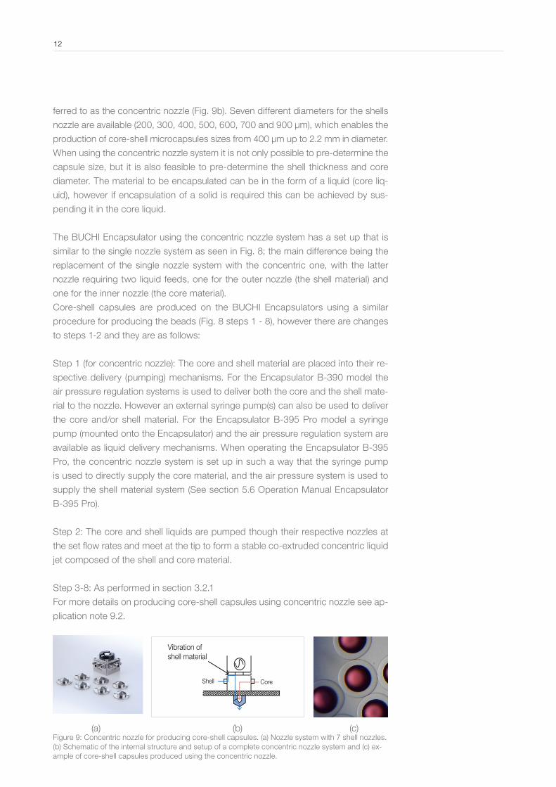
ferred to as the concentric nozzle (Fig. 9b). Seven different diameters for the shells
nozzle are available (200, 300, 400, 500, 600, 700 and 900 µm), which enables the
production of core-shell microcapsules sizes from 400 µm up to 2.2 mm in diameter.
When using the concentric nozzle system it is not only possible to pre-determine the
capsule size, but it is also feasible to pre-determine the shell thickness and core
diameter. The material to be encapsulated can be in the form of a liquid (core liq-
uid), however if encapsulation of a solid is required this can be achieved by sus-
pending it in the core liquid.
The BUCHI Encapsulator using the concentric nozzle system has a set up that is
similar to the single nozzle system as seen in Fig. 8; the main difference being the
replacement of the single nozzle system with the concentric one, with the latter
nozzle requiring two liquid feeds, one for the outer nozzle (the shell material) and
one for the inner nozzle (the core material).
Core-shell capsules are produced on the BUCHI Encapsulators using a similar
procedure for producing the beads (Fig. 8 steps 1 - 8), however there are changes
to steps 1-2 and they are as follows:
Step 1 (for concentric nozzle): The core and shell material are placed into their re-
spective delivery (pumping) mechanisms. For the Encapsulator B-390 model the
air pressure regulation systems is used to deliver both the core and the shell mate-
rial to the nozzle. However an external syringe pump(s) can also be used to deliver
the core and/or shell material. For the Encapsulator B-395 Pro model a syringe
pump (mounted onto the Encapsulator) and the air pressure regulation system are
available as liquid delivery mechanisms. When operating the Encapsulator B-395
Pro, the concentric nozzle system is set up in such a way that the syringe pump
is used to directly supply the core material, and the air pressure system is used to
supply the shell material system (See section 5.6 Operation Manual Encapsulator
B-395 Pro).
Step 2: The core and shell liquids are pumped though their respective nozzles at
the set flow rates and meet at the tip to form a stable co-extruded concentric liquid
jet composed of the shell and core material.
Step 3-8: As performed in section 3.2.1
For more details on producing core-shell capsules using concentric nozzle see ap-
plication note 9.2.
12
Vibration of shell material
Shell Core
(a) (b) (c)Figure 9: Concentric nozzle for producing core-shell capsules. (a) Nozzle system with 7 shell nozzles. (b) Schematic of the internal structure and setup of a complete concentric nozzle system and (c) ex-ample of core-shell capsules produced using the concentric nozzle.
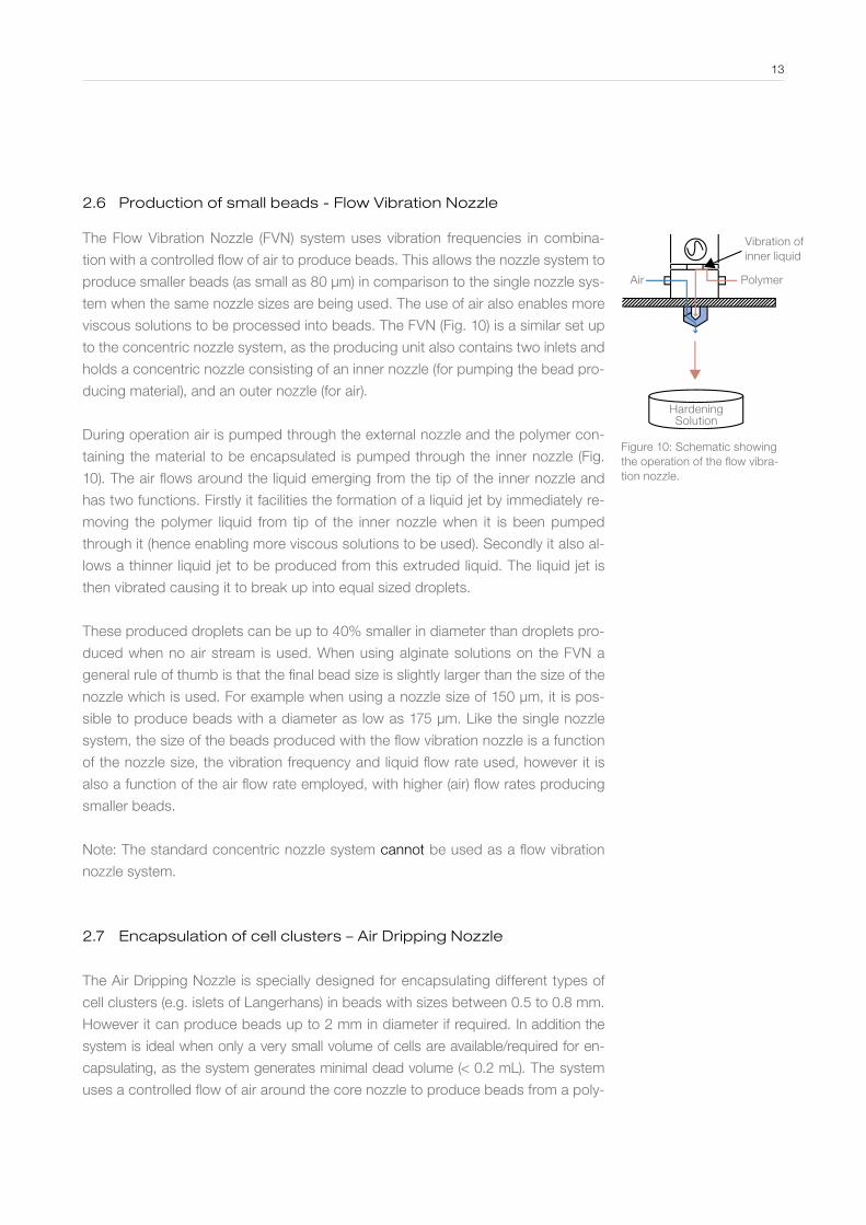
2 .6 Production of small beads - Flow Vibration Nozzle
The Flow Vibration Nozzle (FVN) system uses vibration frequencies in combina-
tion with a controlled flow of air to produce beads. This allows the nozzle system to
produce smaller beads (as small as 80 µm) in comparison to the single nozzle sys-
tem when the same nozzle sizes are being used. The use of air also enables more
viscous solutions to be processed into beads. The FVN (Fig. 10) is a similar set up
to the concentric nozzle system, as the producing unit also contains two inlets and
holds a concentric nozzle consisting of an inner nozzle (for pumping the bead pro-
ducing material), and an outer nozzle (for air).
During operation air is pumped through the external nozzle and the polymer con-
taining the material to be encapsulated is pumped through the inner nozzle (Fig.
10). The air flows around the liquid emerging from the tip of the inner nozzle and
has two functions. Firstly it facilities the formation of a liquid jet by immediately re-
moving the polymer liquid from tip of the inner nozzle when it is been pumped
through it (hence enabling more viscous solutions to be used). Secondly it also al-
lows a thinner liquid jet to be produced from this extruded liquid. The liquid jet is
then vibrated causing it to break up into equal sized droplets.
These produced droplets can be up to 40% smaller in diameter than droplets pro-
duced when no air stream is used. When using alginate solutions on the FVN a
general rule of thumb is that the final bead size is slightly larger than the size of the
nozzle which is used. For example when using a nozzle size of 150 µm, it is pos-
sible to produce beads with a diameter as low as 175 µm. Like the single nozzle
system, the size of the beads produced with the flow vibration nozzle is a function
of the nozzle size, the vibration frequency and liquid flow rate used, however it is
also a function of the air flow rate employed, with higher (air) flow rates producing
smaller beads.
Note: The standard concentric nozzle system cannot be used as a flow vibration
nozzle system.
2 .7 Encapsulation of cell clusters – Air Dripping Nozzle
The Air Dripping Nozzle is specially designed for encapsulating different types of
cell clusters (e.g. islets of Langerhans) in beads with sizes between 0.5 to 0.8 mm.
However it can produce beads up to 2 mm in diameter if required. In addition the
system is ideal when only a very small volume of cells are available/required for en-
capsulating, as the system generates minimal dead volume (< 0.2 mL). The system
uses a controlled flow of air around the core nozzle to produce beads from a poly-
13
Figure 10: Schematic showing the operation of the flow vibra-tion nozzle.
Vibration of inner liquid
PolymerAir
Hardening Solution
mer extruded through the core nozzle.
When encapsulating animal or stem cells into beads; the final particle size should
be <1 mm in diameter and must be strictly adhered too. Sizes above 1 mm can
limit the mass transfer (diffusion) of nutrients and Oxygen throughout the bead
structure resulting in nutrient limitation for the encapsulated cells, hence causing
cell death. This is especially true for the inner most cells of the cluster.
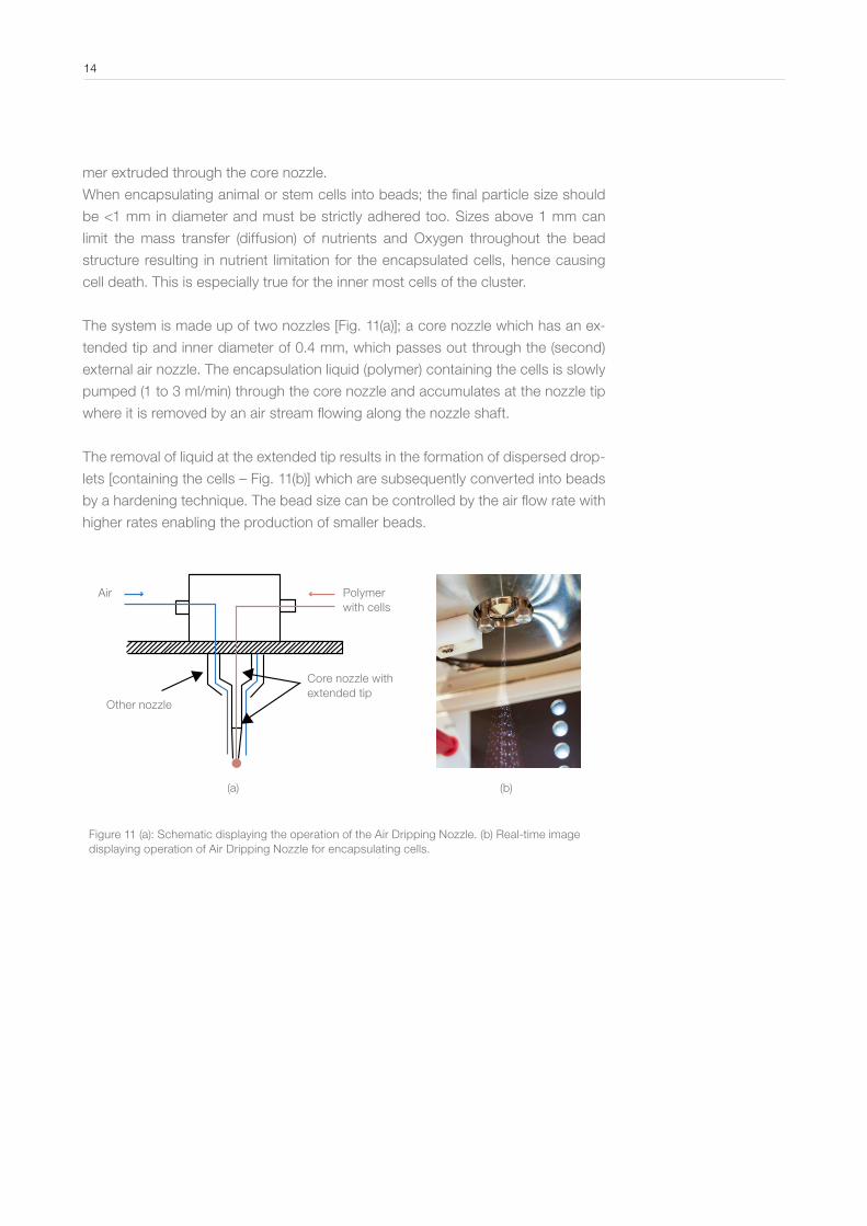
The system is made up of two nozzles [Fig. 11(a)]; a core nozzle which has an ex-
tended tip and inner diameter of 0.4 mm, which passes out through the (second)
external air nozzle. The encapsulation liquid (polymer) containing the cells is slowly
pumped (1 to 3 ml/min) through the core nozzle and accumulates at the nozzle tip
where it is removed by an air stream flowing along the nozzle shaft.
The removal of liquid at the extended tip results in the formation of dispersed drop-
lets [containing the cells – Fig. 11(b)] which are subsequently converted into beads
by a hardening technique. The bead size can be controlled by the air flow rate with
higher rates enabling the production of smaller beads.
Figure 11 (a): Schematic displaying the operation of the Air Dripping Nozzle. (b) Real-time image displaying operation of Air Dripping Nozzle for encapsulating cells.
Air Polymer with cells
Core nozzle with extended tip
Other nozzle
(a) (b)
14

2 .8 Summary of nozzle configurations
Table 1: Summary of different nozzle configurations available for BUCHI Encapsulators
B-390 and B-395 Pro .
Nozzle config.
Encapsulated material
Particles produced
Size range (µm) Special features
IndustrialApplica-tions
Single Solid materials & liquids
Beads 150 - 4000 Encapsulation of solids and liquids into beads in a one-step process
All segments*
Concentric Solid materials & liquids
Core-shell capsules
400 - 2200 Core-shell capsules produced in one-step process
All segments*
Flow Vibration
Solid materials & liquids
Beads 80 - 2000 Produce smaller beads from more viscous solutions
All segments*
Air Dripping
Cell clusters & agglomerates
Beads 500 - 2000 Encapsulation of cell clusters & agglomerates in beads as small as 500 µm
Medical & biotech
* Food & beverage, feed, pharma, biopharma, biotech, medical, cosmetics, enviromental, agriculture and textile industries.
15
3 Process Parameters for Optimized Production
The parameters influencing the production of beads and capsules (and their ef-
fects on production) from alginate solutions when using the single and concen-
tric nozzle systems are outlined below. To obtain optimized production operators
should familiarize themselves with the information.
3 .1 Process parameters influencing production
∙ Nozzle size(s*).
∙ Vibration frequency.
∙ Flow rate of the extruded mixture(s*).
∙ Viscosity of the extruded mixture. *The plural value refers to the concentric nozzle system only.
3 .2 Rules for producing beads/capsules
∙ Larger nozzle sizes result in higher production rates.
∙ Higher frequencies generate smaller beads/capsules.
∙ Lower flow rates generate smaller beads/capsules.
∙ A too low flow rate results in nozzle wetting.
∙ A flow rate too high results in uncontrolled dropled formation.
∙ The dispersion of smaller droplets requires lower voltages.
∙ Higher amplitudes are needed for liquids with high viscosities.
∙ Higher amplitudes are needed for larger nozzle sizes.
3 .3 Rules for bead production only
∙ The bead diameter is around twice the nozzle diameter size.
3 .4 Rules for capsule production only
∙ The final outer diameter of core-shell capsules is around twice the size of the ex-
ternal nozzle.
∙ Higher flow rates of the core material will generate large core diameters.
∙ Higher flow rates of the shell material will generate thicker capsule membranes.
Grid highlighting the parameters influencing production and their effect on bead
size and productivity
16

11592488 en 1201 C / Technical data are subject to change without notice/ Quality Systems ISO 9001 The English version is the original language ver - sion and serves as basis for all translations into other languages.
maj
or
influ
ence
mod
erat
e in
fluen
ce
min
orin
fluen
ce
no
influ
ence
par
amet
erva
riatio
n
adap
tatio
nd
irect
ion
Pro
ce
ss
pa
ram
ete
rs in
flue
nc
ing
be
ad
siz
e a
nd
pro
du
cti
vit
y
ww
w.b
uc
hi.c
om
Ad
ap
tio
n o
f p
roc
es
s p
ara
me
ters
fo
r h
igh
er
vis
co
sit
y s
olu
tio
ns
Op
tim
izin
g p
roc
es
s p
ara
me
ters
Para
met
er
Res
ult
Noz
zle
size
Vib
ratio
n fre
quen
cyFl
ow r
ate
Ele
ctro
de v
olta
geV
isco
sity
Bea
d si
ze
Pro
duct
ivity
Vis
cosi
ty
>>
>>
>>
>>
>>>>
>>
Flow rate inner phase
Flow
rat
e ou
ter
phas
e
Cap
sule
s
Flow
rat
e
Noz
zle
size
Vibration frequency
100
µm
200
µm
300
µm
Noz
zle
size
Droplet size
Flow
rat
e
100
µm200
µm300
µm
Droplet size
Freq
uenc
y
Flow
rat
e2
mL/
min
5 m
L/m
in
10 m
L/m
in
17

4 Structural differences between the Encapsulator B-390 and B-395 Pro
There are three main structural differences between the Encapsulator B-390 and
Encapsulator B-395 Pro models. These differences can affect the characteristics
of the produced particles and can also influence the types of materials used to
make the beads and capsules.
The three structural differences between both Encapsulator B-390 and B-395 Pro
and their functions are described as follows:
∙ Temperature controlled carrier plate and heating block: For increasing/maintain-
ing temperature of extruded polymers by heating up the bead/capsule produc-
tion unit and the nozzle(s) – available on the Encapsulator B-390 model only.
∙ Auoclavable reaction vessel: Encloses the entire bead/capsule production area of
the Encapsulator and enables the process to be performed under full sterile con-
ditions, if required - available on the Encapsulator B-395 model only.
∙ Syringe pump: For volumetrically defined deliver of the polymers/liquids to the
nozzle – Available on the Encapsulator B-395 model only. However an additional
external syringe pump can be obtained from BUCHI and used on the Encapsula-
tor B-390 model. An extra syringe pump can also be used on the Encapsulator
B-395 Pro model when using the concentric nozzle system.
4 .1 Temperature dependent polymer solutions
The Encapsulator B-390 has a temperature controllable carrier plate connected
to a heating block and is incorporated onto the Encapsulator (Fig. 12). The carrier
plate can heat up the nozzle and the pulsation chamber to the desired tempera-
ture (up to 80 °C), and works by conducting heat from the heating block. This de-
vice is very important when using polymers and materials which gel within a cer-
tain temperature range. A prime example is the use of the polymer gelatin which
remains in a liquid state above 35 °C and gels below 35 °C. The temperature
controlled carrier plate enables the temperature of the polymer to remain > 50 °C
when it is being pumped through the production unit and nozzle, hence keeping it
in a liquid form and facilitating pumping, and preventing it from gelling and blocking
the system. This type of production is referred to as Hot-Prilling.
Maintaining the temperature of the polymer > 50 °C during pumping through the
nozzle also allows more viscous solutions to be used and produced into beads
and capsules. High viscous polymer solutions cannot be extruded through the
nozzle orifice especially when using nozzle diameters of ≤ 300 µm. For applica-
tions of this device see application notes 9.4 & 9.7.
18

4 .2 Sterile production and applications
The Encapsulator B-395 Pro can be used to produce bead and capsules under
fully sterile conditions. Sterility is achieved by using a glass reaction vessel (Fig.
13) which fits which around and completely encloses the bead/capsule produc-
tion unit. The reaction vessel is autoclavable along with all other parts which come
into contact with the beads/capsules and the solution used to produce them, en-
suring fully sterile conditions are obtained. This additional feature further advances
the application portfolio of the technology, by enabling it to be applied to numer-
ous biotechnological and medical processes and other fields, which require sterile
conditions, and more importantly allows the technique to be integrated into a GMP
process.
Figure 13: Autoclavable reaction vessel for Encapsulator B-395 Pro which provides a completely sterile environment for the bead/capsule production process.
19
1. Liquid filter2. Connection to electrode3. Screw M4x104. Flange5. Glass cylinder6. O-Ring (6x2) for gap control7. Harvesting valve8. Plastic clamp9. Silicon tube (6x9) of drain line10. Air filter11. Bead producing unit12. Bypass knob13. Syringe14. Cover plate15. Bypass cup16. Support bar17. Filter of drain line18. Flat silicone fitting19. Base plate20. Foot
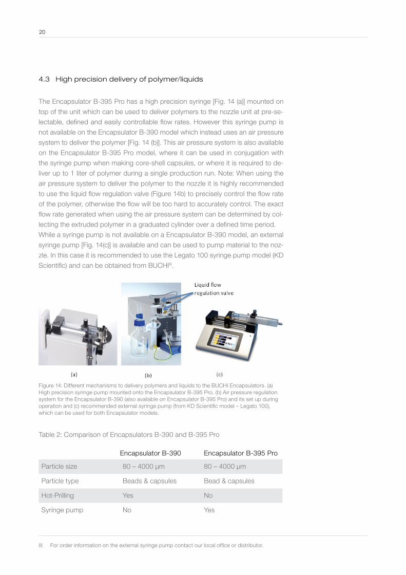
4 .3 High precision delivery of polymer/liquids
The Encapsulator B-395 Pro has a high precision syringe [Fig. 14 (a)] mounted on
top of the unit which can be used to deliver polymers to the nozzle unit at pre-se-
lectable, defined and easily controllable flow rates. However this syringe pump is
not available on the Encapsulator B-390 model which instead uses an air pressure
system to deliver the polymer [Fig. 14 (b)]. This air pressure system is also available
on the Encapsulator B-395 Pro model, where it can be used in conjugation with
the syringe pump when making core-shell capsules, or where it is required to de-
liver up to 1 liter of polymer during a single production run. Note: When using the
air pressure system to deliver the polymer to the nozzle it is highly recommended
to use the liquid flow regulation valve (Figure 14b) to precisely control the flow rate
of the polymer, otherwise the flow will be too hard to accurately control. The exact
flow rate generated when using the air pressure system can be determined by col-
lecting the extruded polymer in a graduated cylinder over a defined time period.
While a syringe pump is not available on a Encapsulator B-390 model, an external
syringe pump [Fig. 14(c)] is available and can be used to pump material to the noz-
zle. In this case it is recommended to use the Legato 100 syringe pump model (KD
Scientific) and can be obtained from BUCHIIII.
Figure 14: Different mechanisms to delivery polymers and liquids to the BUCHI Encapsulators. (a) High precision syringe pump mounted onto the Encapsulator B-395 Pro. (b) Air pressure regulation system for the Encapsulator B-390 (also available on Encapsulator B-395 Pro) and its set up during operation and (c) recommended external syringe pump (from KD Scientific model – Legato 100), which can be used for both Encapsulator models.
Table 2: Comparison of Encapsulators B-390 and B-395 Pro
Encapsulator B-390 Encapsulator B-395 Pro
Particle size 80 – 4000 µm 80 – 4000 µm
Particle type Beads & capsules Bead & capsules
Hot-Prilling Yes No
Syringe pump No Yes
20
III For order information on the external syringe pump contact our local office or distributor.

Sterile work No Yes
Aseptic work* Yes Yes
Dead volume ~ 2 mL ~ 0.25 mL
Options External syringe pump4 nozzle configurations
External syringe pump4 nozzle configurations
*Achieved by placing instrument under a laminar flow cabinet and following aseptic technique.
5 Quick-start guide for the Single Nozzle system
Table 3 displays some pre-determined parameters used to produce beads in the
size ranges outlined when alginate solutions were used for the single nozzle sys-
tem. These values can act as a reference or starting value for the operator if using
a similar alginate typeIV and concentration. An empirical approach is then used (be-
ginning with the reference value) to determine the optimal production parameters.
Table 3: Parameter range to produce Ca-alginate beads (in the sizes ranges out-
lined) when using the single nozzle system on the Encapsulator B-390 and B-395
Pro.
Nozzle (µm)
Flow rate range (ml/min)* (Production)
Air pressure(bar)
Optimal frequency range (Hz)**
Amplitude Size range of produced beads (µm)
80 1.1 0.5 - 0.7 1300 - 3000 1 - 4 120 - 200
120 1.5 - 1.8 0.5 - 0.7 1000 - 2500 1 - 4 200 - 300
150 2.3 - 2.8 0.4 - 0.6 800 - 1800 1 - 3 260 - 350
200 3.5 - 4.5 0.4 - 0.6 600 - 1200 1 - 3 350 - 450
300 6.0 - 8.0 0.3 - 0.5 400 - 800 1 - 3 550 - 700
450 11 - 15 0.3 - 0.5 200 - 500 1 - 4 700 - 1150
750 19 - 25 0.3 - 0.5 40 - 300 6-9 1150 - 1800
1000 30 - 40 0.3 - 0.6 40 - 220 6-9 1600 - 2400
* This flow rate value can be obtained using the high precision syringe pump which comes sepa-rately or is mounted onto the Encapsulator B-395 Pro.**Frequency range was determined when using the 2% low viscosity grade alginate solution for the 750 and 1000 µm nozzle sizes, 1.5% alginate solution for 150 – 450 µm nozzle sizes and 1.2% alginate solution for the 80 and 120 µm nozzle sizes.
21
IV Recommended to use BUCHI Alginate. Contact our local office or distributor for order information.
Before beginning production
∙ Decide on the required bead size or size range and chose the appropriate nozzle
size from Table 3.
∙ Choice the polymer to produce the beads and the material to be encapsulated.
Note: If alginate is not used to produce the beads, the operator can still use the
values in Table 3 as a reference point and make changes accordingly, after per-
forming initial tests.
∙ Chose a frequency and polymer flow rate value (for the Encapsulator B-390 use
the air pressure values displayed) from the range recommended in Table 3 for
the selected nozzle size. Table 3 displays a large range of values for both the fre-
quency and flow rate, so the operator should select an average value displayed.
∙ Select an amplitude value, again selecting the average. Note: Amplitude has
minimal effect on the production process except when using 750 and 1000 µm
nozzles.
Beginning production
∙ Firstly pump the polymer material to the nozzle using either the syringe pump (En-
capsulator B-395 Pro) or air pressure system (Encapsulator B-390). Note: When
using the air pressure system to deliver the polymer to the nozzle it is highly rec-
ommended to use the liquid flow regulation valve [Figure 14(b)] to precisely con-
trol the flow rate of the polymer.
∙ Increase the pumping speed until a stable liquid jet has formed [Fig. 15(a)]. For
the B-395 Pro the operator can increase the speed by pressing the turbo but-
ton (on the syringe pump control panel) and leaving at this speed for 3-5 sec-
onds. After formation of a stable jet, turn off the turbo function and the liquid jet
will stabilize to the set flow rate valueV . For the air pressure system, after obtain-
ing a stable liquid jet, slightly decrease the pumping speed using the liquid-flow
regulation valve. Note: When using the air pressure system to deliver the polymer
to the nozzle it is highly recommended to use the liquid flow regulation valve (Fig-
ure 14b) to precisely control the flow rate of the polymer, otherwise the flow will
be too hard to accurately control. The exact flow rate generated when using the
air pressure system can be determined by collecting the extruded polymer in a
graduated cylinder over a defined time period.
22
V The turbo function is necessary as it breaks the initial surface tension of the extruded polymer at the nozzle tip resulting in liquid jet formation, otherwise the polymer passes through the nozzle in the form of droplets.
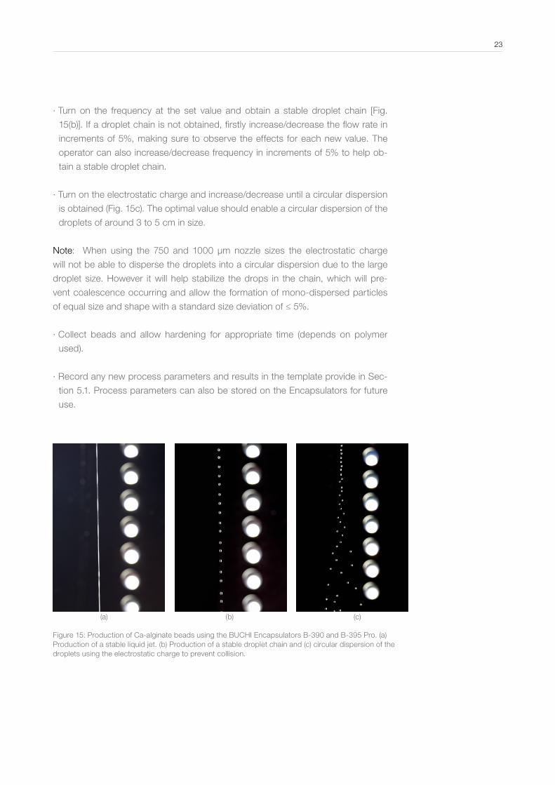
∙ Turn on the frequency at the set value and obtain a stable droplet chain [Fig.
15(b)]. If a droplet chain is not obtained, firstly increase/decrease the flow rate in
increments of 5%, making sure to observe the effects for each new value. The
operator can also increase/decrease frequency in increments of 5% to help ob-
tain a stable droplet chain.
∙ Turn on the electrostatic charge and increase/decrease until a circular dispersion
is obtained (Fig. 15c). The optimal value should enable a circular dispersion of the
droplets of around 3 to 5 cm in size.
Note: When using the 750 and 1000 µm nozzle sizes the electrostatic charge
will not be able to disperse the droplets into a circular dispersion due to the large
droplet size. However it will help stabilize the drops in the chain, which will pre-
vent coalescence occurring and allow the formation of mono-dispersed particles
of equal size and shape with a standard size deviation of ≤ 5%.
∙ Collect beads and allow hardening for appropriate time (depends on polymer
used).
∙ Record any new process parameters and results in the template provide in Sec-
tion 5.1. Process parameters can also be stored on the Encapsulators for future
use.
(a) (b) (c)
Figure 15: Production of Ca-alginate beads using the BUCHI Encapsulators B-390 and B-395 Pro. (a) Production of a stable liquid jet. (b) Production of a stable droplet chain and (c) circular dispersion of the droplets using the electrostatic charge to prevent collision.
23
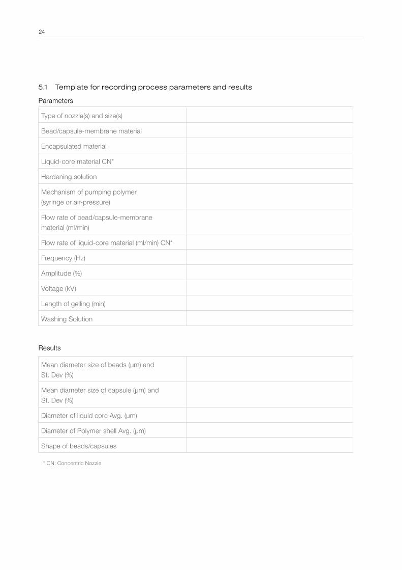
5 .1 Template for recording process parameters and results
Parameters
Type of nozzle(s) and size(s)
Bead/capsule-membrane material
Encapsulated material
Liquid-core material CN*
Hardening solution
Mechanism of pumping polymer
(syringe or air-pressure)
Flow rate of bead/capsule-membrane
material (ml/min)
Flow rate of liquid-core material (ml/min) CN*
Frequency (Hz)
Amplitude (%)
Voltage (kV)
Length of gelling (min)
Washing Solution
Results
Mean diameter size of beads (µm) and
St. Dev (%)
Mean diameter size of capsule (µm) and
St. Dev (%)
Diameter of liquid core Avg. (µm)
Diameter of Polymer shell Avg. (µm)
Shape of beads/capsules
* CN: Concentric Nozzle
24
5 .2 Characteristics of the beads/capsules produced using the BUCHI Encapsulators B-390 and B-395 Pro and the characteristics of the production technique
Bead/capsule characteristics Characteristics of the production technique
∙ Mono and singly dispersed
∙ Homogenous and spherical shape ∙ Size ranges:
∙ Bead diameter 80 µm - 4 mm
∙ Capsule diameter 400 µm - 2.2 mm
∙ Shell thickness 100 µm – 500 µm
∙ Core diameter 150 µm – 1.5 mm
∙ Narrow size distribution (< ± 5% from the mean size)
∙ Can be produced from a range of dif-ferent polymers and core liquids (in-cluding hydrophobic liquids)
∙ Can be produced from temperature dependent polymer solutions such as gelatin, waxes etc.
∙ Sterile particles (Encapsulators B-395 Pro only)
∙ Relatively easy set up and simple operation
∙ Gentle technique (encapsulation of cells)
∙ Fully controllable operation
∙ Low operating (and servicing) costs
∙ High efficiency
∙ Produce a range of different sized cap-sules in separate batches
∙ Ability to extrude viscous solutions (FVN)
∙ Repeatable results
∙ Operate under sterile conditions (Encapsu-lators B-395 Pro only)
∙ GMP compliant
∙ One step process to produce beads & capsules
25
6 Large Scale Production
The BUCHI Encapsulators are especially designed for performing innovative R&D work
for many different sectors, and can also be used in industry for producing small quantities
of beads and capsules for commercial purposes. In the latter case they are mostly used
to encapsulate high-value low-volume materials such as specialized drugs or stem/ani-
mal cells. The production rate of a BUCHI Encapsulator is mainly dependent on the di-
ameter of the nozzle being used, with increasing diameters resulting in higher produc-
tion rates. Table 3 shows the production rates which are obtainable, and show that with
the largest nozzle size a production rate of 40 mL/min (2.6 L/hr) can be reached. How-
ever, these rates fall well short of the quantities (up to tons/day) required by most indus-
tries planning to manufacture encapsulated products for the market places.
After developing and optimizing a bead/capsules production process at lab scale (us-
ing a BUCHI Encapsulator), the next step for most companies will be to scale up the
process. The main goal will be to produce higher quantities of the particles without in-
curring significant changes in their properties. Scale up (increased production) of the
Prilling by Vibration technique can be successfully achieved by increasing the number
of nozzles used for polymer extrusion, and the increased productivity rate is a direct
function of the number of nozzles used. Provided the nozzle size, vibrational frequen-
cy, amplitude and flow rate are similar to the values used at lab-scale (as well as being
constant across all nozzles); beads and capsules with similar characteristics can be ob-
tained at much high quantities.
BUCHI offers a new multi nozzle Encapsulator which is a scaled up version of its En-
capsulator B-390. This is the device of choice for further scale up of encapsulation
process developed using BUCHI Encapsulator at lab scale and offers low to median
production levels. The device has 6 nozzles held on a steel plate, and enables a 6-fold
increase in the quantity of beads. For this device further increases in production vol-
umes can be achieved by adding more nozzles (in multiples of 6) to the machine. While
used for pilot-scale production and tests, this device can also be for industrial produc-
tion. For further information on the BUCHI Multi-Nozzle Encapsulator contact your local
office/distributor.
Some companies now also offer large scale Encapsulators for industrial production,
with one such company being Brace GmbH (www.brace.de). The Brace large scale En-
capsulators can have hundreds of nozzles fit onto the one device and have the capabil-
ity to produce tons of encapsulated material per day. These Encapsulators work on the
same principle as the BUCHI Encapsulators and are seen as the machines of choice for
further scaling up encapsulation production process developed using the BUCHI one-
nozzle and multi nozzle Encapsulator.
26
27
No extrusion of polymer solution through nozzle
Suggested
Solution
Possible
cause
Problem
Pump speed is too
low
Filter within bead
producing unit is
blocked
Polymer solution is
too viscous
Bead producing
unit/nozzle is
blocked
Increase pump
speed
Change filter (Man-
ual section 5.4)
Dilute polymer solu-
tion or use Flow vi-
bration Nozzle (sec-
tion 2.6)
Clean bead pro-
duction unit/nozzle:
For alginate, soak
the unit in 0.1 M
NaOH for 1 hr and
rinse with water, or
place in a sonica-
tion bath for 5 min.
For gelatin soak in
hot water (> 60 °C)
and flush, or soni-
cate as above.
Inadequate or no dispersion of droplets when using electrostatic charge
Suggested
Solution
Suggested
Solution
Possible
cause
Possible
cause
Problem
Electrode is not turned on Electrode is not connected
properly (B-390 model)
The electrode is not
cleaned
Turn on electrode Connect properly (Manual
section 5.6)
Clean electrode
Droplets are too big Droplets are repelled from
landing in gelling vessel
Droplets are hitting the wall
of the gelling vessel
For Nozzle sizes ≥ 750 µm
the electrostatic device will
not disperse droplets
Place grounding hook into
gelling solution
Charge is too high, de-
crease appropriately
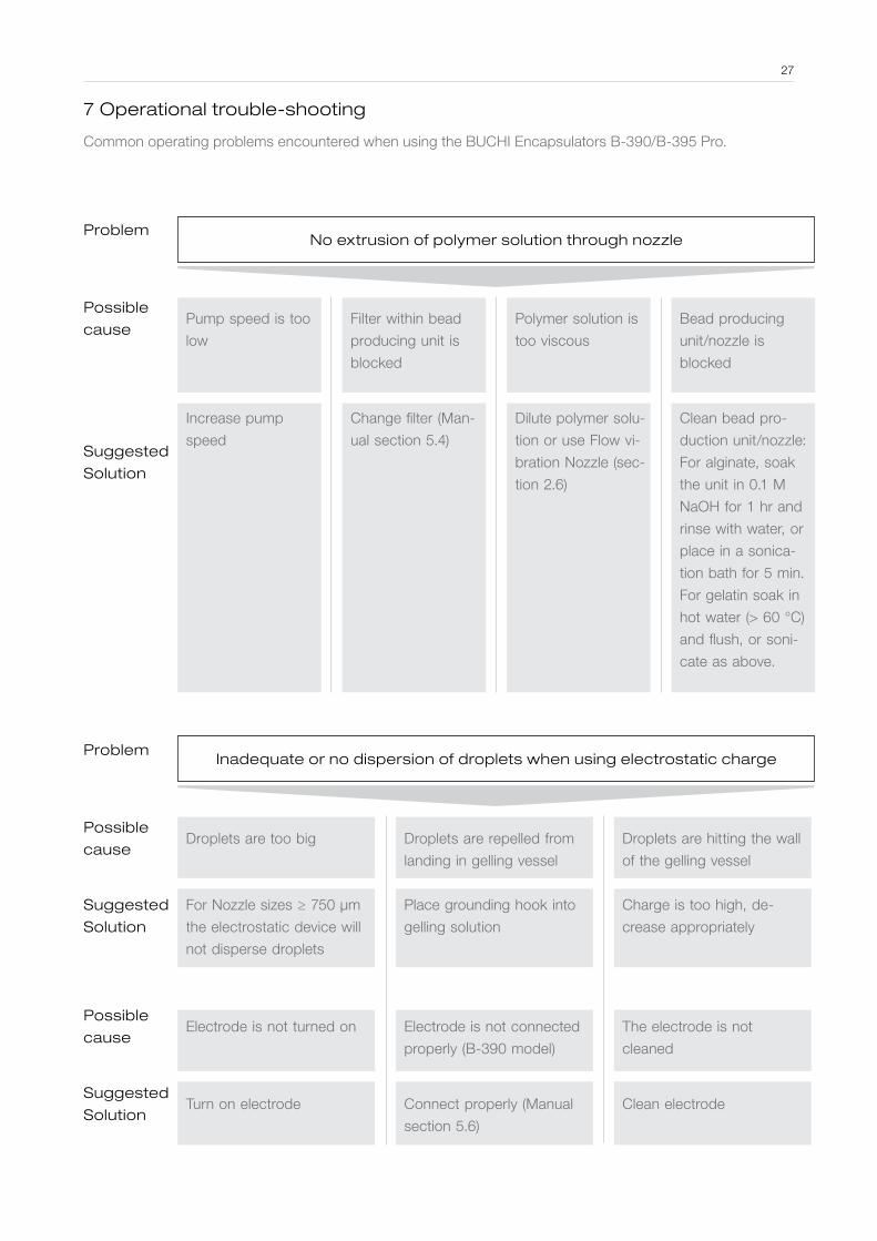
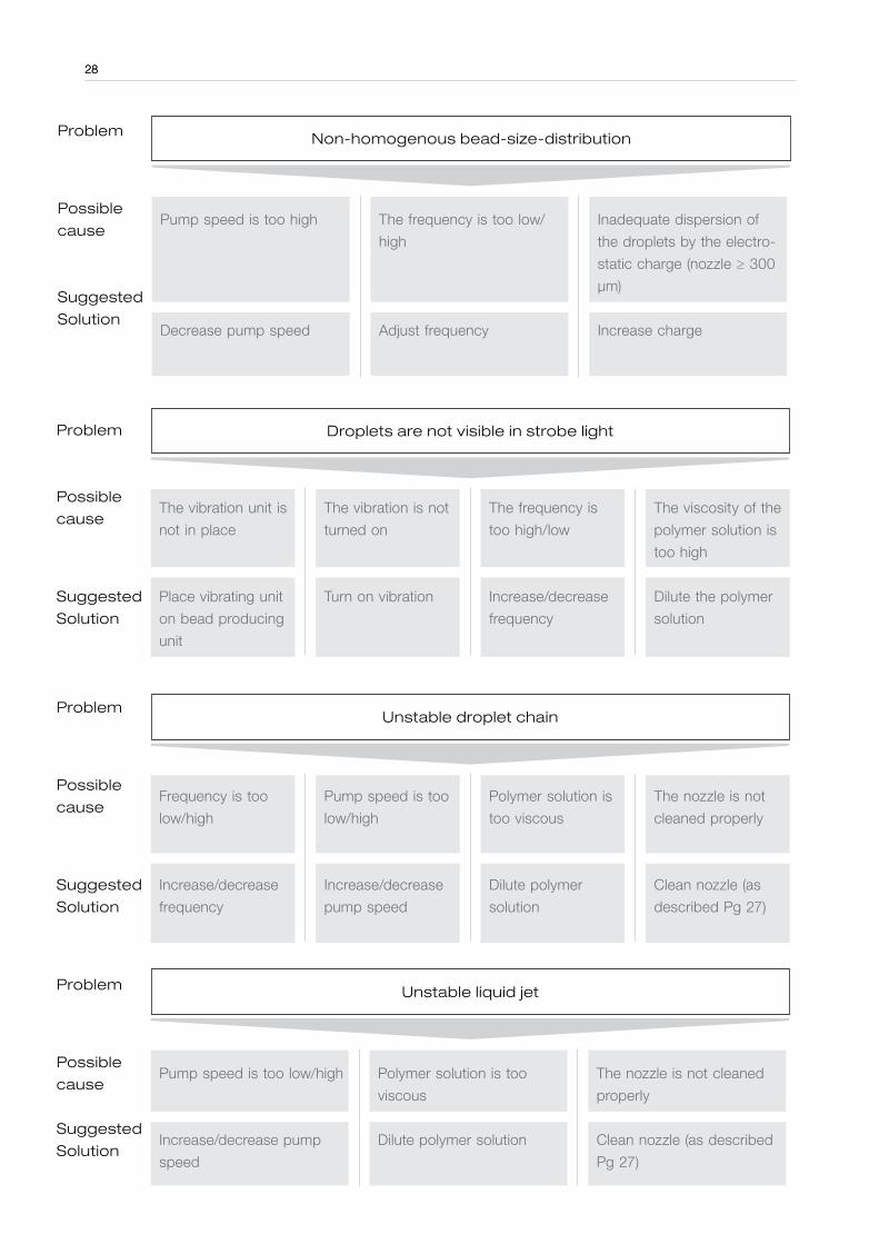
7 Operational trouble-shooting
Common operating problems encountered when using the BUCHI Encapsulators B-390/B-395 Pro.
28
Droplets are not visible in strobe light
Unstable droplet chain
Non-homogenous bead-size-distribution
Suggested
Solution
Suggested
Solution
Suggested
Solution
Possible
cause
Possible
cause
Possible
cause
Problem
Problem
Problem
The vibration unit is
not in place
The vibration is not
turned on
The frequency is
too high/low
The viscosity of the
polymer solution is
too high
Place vibrating unit
on bead producing
unit
Turn on vibration Increase/decrease
frequency
Dilute the polymer
solution
Frequency is too
low/high
Pump speed is too
low/high
Polymer solution is
too viscous
The nozzle is not
cleaned properly
Increase/decrease
frequency
Increase/decrease
pump speed
Dilute polymer
solution
Clean nozzle (as
described Pg 27)
Pump speed is too high The frequency is too low/
high
Inadequate dispersion of
the droplets by the electro-
static charge (nozzle ≥ 300
μm)
Decrease pump speed Adjust frequency Increase charge
Unstable liquid jet
Suggested
Solution
Possible
cause
Problem
Pump speed is too low/high Polymer solution is too
viscous
The nozzle is not cleaned
properly
Increase/decrease pump
speed
Dilute polymer solution Clean nozzle (as described
Pg 27)
28
8 References
[1] Whelehan, M. & Marison I.W. Journal of Microencapsulation. 2011;28:669-88.[2] Gibbs, B.F. et. al. International Journal of Food Sciences and Nutrition. 1999;50:213-24.[3] Serp, D. et. al. Biotechnology and Bioengineering. 2000;70:41-53.[4] Heinzen, C. et. al. Fundamentals of cell immobilisation technology. Dordrecht: Kluwer Academic Publishers; 2004:257 - 75.[5] Whelehan, M. The present role of microencapsulation. Eurolab. 2012:16-17.[6] Hoad, C. et. al., Food Hydrocolloids. 2011;25:1190-1200.[7] Madziva, H. et. al., Journal of Microencapsulation. 2005;22:343-51.[8] Chandramouli, V. et. al., Journal of Microbiological Methods. 2004;56:27-35.[9] Bhathena, J. et. al., Journal of Medicinal Food. 2009;12:310-319.[10] Lyer, C. et. al., Letters in Applied Microbiology. 2005;41:493-497.[11] Anjani, K. et. al., International Dairy Journal. 2007;17:79-86.[12] Sun-Waterhouse, D. et. al., Food Bioprocess Technology. 2012;5:3090-3102.[13] Sun-Waterhouse, D. et. al., Food Chemisty. 2011;126:1049-1056.[14] Wang, W.et. al., Food Research International. 2013;54:837-851.[15] Soliman, E.A. et. al., Journal of Encapsulation & Adsorption Science. 2013;3:45-55.[16] Perez-Moral, N. et. al., Food Hydrocolloids. 2013;31:114-120.[17] Wang, Q. et. al., Journal of Applied Microbiology. 2009;107:1781-1788.[18] Zvonar, A. et al., Journal of Microencapsulation. 2009;26:748-759.[19] Zvonar, A. et al., International Journal of Pharmaceutics. 2010;388:151-158.[20] Metz, T. et. al., Cell Biochemistry & Biophysics. 2005;43:77-85.[21] Genc, L. & Butuktiryaki, S. Pharmaceutical development & technology. 2014;19:42-47.[22] Wenk, E. et. al., Journal of Controlled Release. 2008;132:26-34.[23] Ma, Y. et. al., Applied & Environmental Microbiology. 2008;74:4799-4805.[24] Weber, W. et. al., Journal of Biotechnology. 2006;123:155-163.[25] Arenas-Gamboa, A.M. et. al., Journal of Wildlife diseases. 2009;45:1021-1029.[26] Arenas-Gamboa, A.M. et. al., Infection & Immunity. 2008;76:2448-2455.[27] Paul, A. et. al., Cell Transplantation. 2012;21:2735-2751.[28] Penolazzi, L. et. al., Tissue Engineering Part C-Methods. 2010;16:141-155.[29] Kulamarva, A. et. al., Nanotechnology. 2009;20:1-7.[30] Fluri, D.A. et. al., Journal of Controlled Release. 2008;131:211-219.[31] Brandenberger H; Nussli D; Piech V; Widmer F. Journal of Electrostatics. 1999;45(3):227-38.
29

Part B: Application Notes
9.1 Production of Ca-alginate beads 31
9.2 Production of core-shell capsules 35
9.3 Encapsulation of hydrophobic liquids within microbeads 39
9.4 Production of hard fat capsules 42
9.5 Producing large Ca-alginate micro-beads 45
9.6 Producing cellulose sulphate microcapsules 47
9.7 Encapsulation within Gelatin beads 50
9.8 Encapsulation of probiotics in whey protein beads 53
9.9 Encapsulation of Methotrexate in alginate & hyaluronic acid microcapsules 55
For more application notes please visit http://www.buchi.com/en/applications/finder
30

9 .1 Production of Ca-alginate beads
Encapsulator B-390 / B-395 Pro: Production of Ca-alginate Beads with a size of
560 - 680 µm
9 .1 .1 Introduction
Ca-alginate micro-beads can be used to encapsulate a wide variety of materials.
This method enables the encapsulated substance (termed encapsulant) to be pro-
tected from many different environmental conditions such as oxygen, heat, pH
etc., and can help prolong its shelf life. In addition encapsulation also enables the
controlled release of the encapsulant.
The following example substances can be encapsulated using this method:
∙ Cells (yeast, bacteria and animal cells)
∙ APIs (hydrophobic)
∙ Essential oils & hydrophobic liquids
∙ Flavors & fragrances
∙ Vitamins & minerals
∙ Bioactive materials
∙ Enzymes
∙ Detergents
∙ Cosmetics
By using the BUCHI Encapsulator B-390/B-395 Pro, with a 300 µm nozzle in
place, it is possible to control the size of the micro-beads within the range of 550
µm to 700 µm, while obtaining a narrow size distribution (± 5%).
With the use of one of the additional nozzles (eight in total) provided with the En-
capsulator it is possible to create particles in the size range of 150 to 2000 µm.
Aim: To produce Ca-alginate micro-beads using the Encapsulator B-390/B-395
Pro with the 300 µm nozzle
9 .1 .2 Equipment
∙ Instrument: Encapsulator B-390/B-395 Pro
∙ Set up: Single-flow nozzle system – 300 µm nozzle
∙ Pumping: Syringe pump/air pressure system
∙ Blender: Any kind of blender can be used (see Fig. 9.1-1)
9 .1 .3 Chemicals and Materials
∙ Polymer: 1.5% (w/v) Na-alginate (BUCHI) dissolved in H2O using a blender
∙ Gelling sol: 100 mM CaCl2
∙ Deion. water: Dissolving the Na-Alginate
∙ Encapsulant: Not used in this method (materials listed in section 9.1.1 can be
used with a max. conc. of 20%)
31

32
Figure 9.1-1: Polymer preparation
Figure 9.1-2: (a) Alginate drop-let chain produced using set out parameters. (b) Dispersion of the droplets using electro-static charge.
9 .1 .4 Procedure and Parameters
Procedure
Add 4.0 g of Na-alginate powder into 200 mL of water. Use the blender to dissolve
the Na- alginate completely (Fig. 9.1-1). Let the solution sit until it is clear and has
released all the air within it. The air bubbles can be removed quicker by placing in a
sonication bath or placing under vacuum. If a material is to be encapsulated within
the beads, add the material to the alginate solution and mix again.
Begin production (hardening) after obtaining a stable droplet chain (Fig. 9.1-2a).
Use electrostatic charge to disperse droplets and prevent collision (Fig. 9.1-2b).
Deliver 10 mL of alginate through nozzle into hardening/gelling bath containing 100
mL of CaCl2. Allow to harden for 30 min (T=0, when last drop lands in gelling bath).
Wash with water and examine under a microscope.
The following process parameters may vary slightly and are dependent on the type
of alginate used.
Process parameters I
∙ Flow rate 7.0 mL/min
∙ Frequency 600 Hz
∙ Pressure 0.5 bar
∙ Amplitude 2
∙ Charge 1000 - 2500 V
Process parameters II
∙ Flow rate 7.0 mL/min
∙ Frequency 750 Hz
∙ Pressure 0.5 bar
∙ Amplitude 2
∙ Charge 1000 - 2000 V
Process parameters III
∙ Flow rate 7.8 mL/min
∙ Frequency 600 Hz
∙ Pressure 0.5 bar
∙ Amplitude 2
∙ Charge 1000 - 2500 V
Hint: Increasing / decreasing micro-bead diameter
After the initial production of micro-beads and size determination, the operator can
increase/decrease the diameter of the produced micro-beads in additional pro-
duction runs (using the same nozzle size) by varying certain key parameters.
32
33
General rule:
For any given nozzle size there are two main parameters which will affect size dur-
ing production – the frequency and the flow rate.
∙ Higher frequencies generate smaller microbeads.
∙ Lower polymer flow rates generate smaller microbeads.
The production of bigger/smaller micro-beads will have an effect on the amount of
the charge required to adequately disperse the droplets and prevent coalescence
from occurring.
General rule:
Smaller microbeads require lower electrostatic charges to adequately disperse the
droplets and prevent colliding.
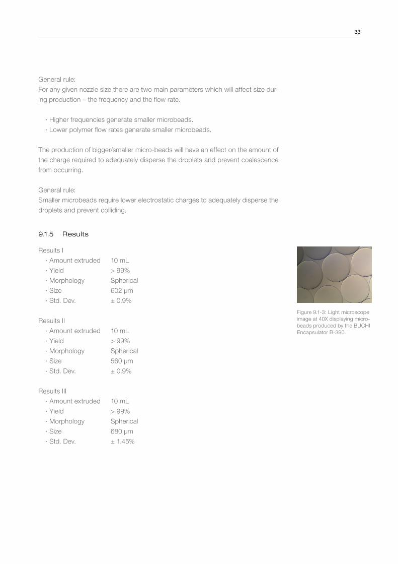
9 .1 .5 Results
Results I
∙ Amount extruded 10 mL
∙ Yield > 99%
∙ Morphology Spherical
∙ Size 602 µm
∙ Std. Dev. ± 0.9%
Results II
∙ Amount extruded 10 mL
∙ Yield > 99%
∙ Morphology Spherical
∙ Size 560 µm
∙ Std. Dev. ± 0.9%
Results III
∙ Amount extruded 10 mL
∙ Yield > 99%
∙ Morphology Spherical
∙ Size 680 µm
∙ Std. Dev. ± 1.45%
Figure 9.1-3: Light microscope image at 40X displaying micro-beads produced by the BUCHI Encapsulator B-390.
33

34
9 .1 .6 Conclusion
The BUCHI Encapsulator B-390 / B-395 Pro are able to produce spherical alginate
micro-beads in the size range of 560 - 680 µm with the 300 µm nozzle. The par-
ticles achieved have an extremely narrow size distribution.
General rule: Final micro-bead diameter is about twice the size of the selected
nozzle size, however this can vary and depends on the encapsulated material,
which can cause shrinking and swelling effects.
9 .1 .7 References
[1] Whelehan and Marison (2011). Microencapsulation using vibrating technology.
Journal of Microencapsulation 28:669-688.
34

35
9 .2 Production of core-shell capsules
Encapsulator B-390/B-395 Pro: Production of core-shell microcapsules for en-
capsulation of hydrophobic liquids and oils
9 .2 .1 Introduction
Hydrophobic liquid-core microcapsules play a very important role in numerous in-
dustries and have being mainly used in the perfume, cosmetic, paper and agricul-
tural industry, but recently they have found application in drug and bioactive (food
industry) delivery.
The method allows most oils or hydrophobic liquids to be encapsulated and the
following substances are common examples:
∙ Perfume oils
∙ Essential oils
∙ Fatty acids
∙ Flavors and fragrances
∙ Omega 3 oils
∙ Hydrophobic APIs
∙ Hydrocarbons
∙ Detergents
∙ Cosmetics
This method enables the encapsulated substance (termed encapsulant) to be pro-
tected from many different environmental conditions such as oxygen, heat, pH
etc., and can help prolong its shelf life. In addition encapsulation also enables the
controlled release of the encapsulant.
In comparison to encapsulation of oils and hydrophobic liquids in microbeads
(Section 9.3) the use of core-shell capsules has the following advantages:
∙ Higher loading of encapsulant - up to 40%
∙ No encapsulant on the surface of the capsules (complete envelopment)
∙ Greater protection of the encapsulant
∙ Release profile: burst or delayed
With the different nozzles supplied with the BUCHI Encapsulator it is possible to
obtain capsules sizes between 400 - 2200 µm, while obtaining a narrow size dis-
tribution (± 5%).
Aim: Production of sunflower oil-core microcapsules with a Ca-alginate membrane
(Fig. 9.2-3).
35

36
9 .2 .2 Equipment
∙ Instrument: Encapsulator B-390/B-395 Pro
∙ Set up: Concentric nozzle system: Shell 400 µm & core nozzle 150 µm
∙ Pumping: Air pressure (shell) & syringe pump/air pressure (core)
∙ Blender: Any kind of blender can be used (see Fig. 9.2-1)
9 .2 .3 Chemicals and Materials
∙ Polymer: 2.0% (w/v) Na-alginate (BUCHI) dissolved using a blender
∙ Gelling sol: 100 mM CaCl2 containing 0.1% Tween 80
∙ Material: Sunflower oil
∙ Deion. water
9 .2 .4 Procedure and Parameters
Add 4.0 g of Na-alginate powder into 200 mL of water. Use the blender to dissolve
the Na-alginate completely (Fig. 9.2-1). Let the solution sit until it is clear and has
released all the air within it. The air bubbles can also be removed by placing in a
sonication bath or under vacuum.
Dissolve 1.47 g of CaCl2 (dihydrate) and 0.1 mL of Tween 80 in 100 mL of water.
The Tween 80 is added to reduce the surface tension of the gelling solution, which
prevents capsules bursting during their entry into the solution.
The alginate should be first pumped through the shell nozzle. After obtaining a sta-
ble droplet chain, the pumping of the sunflower oil through the core nozzle should
begin. Slight adjustment (to the set up values) of both flow rates will be required to
obtain a stable chain of mono-centric droplets (Fig. 9.2-2), which produce the liq-
uid-core microcapsules (Fig. 9.2-3) after landing in the gelling bath. Allow the parti-
cles to harden in the CaCl2 bath for 20 min. Wash the capsules with plenty of water.
Note: When using the air pressure system to deliver the polymer to the nozzle it is
highly recommended to use the liquid flow regulation valve (Figure 14b) to precisely
control the flow rate of the polymer, otherwise the flow will be too hard to accu-
rately control. The exact flow rate generated when using the air pressure system
can be determined by collecting the extruded polymer in a graduated cylinder over
a defined time period.
9 .2 .5 Process parameters
∙ Flow rate 10 (shell) & 1.5 (core) mL/min
∙ Frequency 600 Hz
∙ Pressure 0.5 bar
∙ Amplitude 3
∙ Charge > 2000 V
Figure 9.2-1: Polymer preparation
36
37
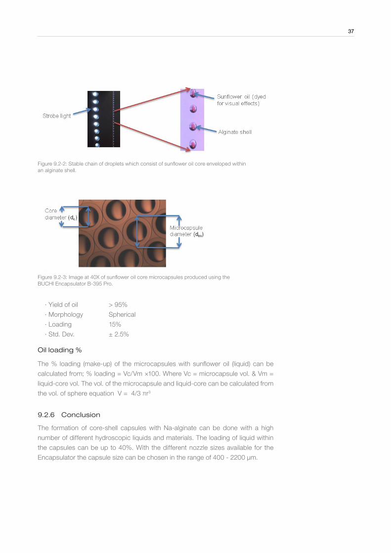
Figure 9.2-2: Stable chain of droplets which consist of sunflower oil core enveloped within an alginate shell.
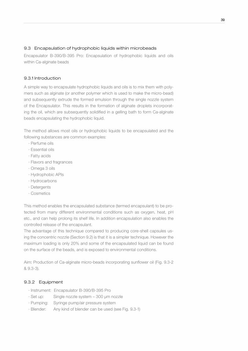
Figure 9.2-3: Image at 40X of sunflower oil core microcapsules produced using the BUCHI Encapsulator B-395 Pro.
∙ Yield of oil > 95%
∙ Morphology Spherical
∙ Loading 15%
∙ Std. Dev. ± 2.5%
Oil loading %
The % loading (make-up) of the microcapsules with sunflower oil (liquid) can be
calculated from; % loading = Vc/Vm ×100. Where Vc = microcapsule vol. & Vm =
liquid-core vol. The vol. of the microcapsule and liquid-core can be calculated from
the vol. of sphere equation V = 4/3 πr3
9 .2 .6 Conclusion
The formation of core-shell capsules with Na-alginate can be done with a high
number of different hydroscopic liquids and materials. The loading of liquid within
the capsules can be up to 40%. With the different nozzle sizes available for the
Encapsulator the capsule size can be chosen in the range of 400 - 2200 µm.
37

38
9 .2 .7 References
[1] Whelehan and Marison (2011). Microencapsulation using vibrating technology.
Journal of Microencapsulation 28:669-688.
[2] Whelehan and Marison (2011). Capsular perstraction as a novel methodol-
ogy for the recovery and purification of geldanamycin. Biotechnology Progress
27:669-1077.
38
39
9 .3 Encapsulation of hydrophobic liquids within microbeads
Encapsulator B-390/B-395 Pro: Encapsulation of hydrophobic liquids and oils
within Ca-alginate beads
9 .3 .1 Introduction
A simple way to encapsulate hydrophobic liquids and oils is to mix them with poly-
mers such as alginate (or another polymer which is used to make the micro-bead)
and subsequently extrude the formed emulsion through the single nozzle system
of the Encapsulator. This results in the formation of alginate droplets incorporat-
ing the oil, which are subsequently solidified in a gelling bath to form Ca-alginate
beads encapsulating the hydrophobic liquid.
The method allows most oils or hydrophobic liquids to be encapsulated and the
following substances are common examples:
∙ Perfume oils
∙ Essential oils
∙ Fatty acids
∙ Flavors and fragrances
∙ Omega 3 oils
∙ Hydrophobic APIs
∙ Hydrocarbons
∙ Detergents
∙ Cosmetics
This method enables the encapsulated substance (termed encapsulant) to be pro-
tected from many different environmental conditions such as oxygen, heat, pH
etc., and can help prolong its shelf life. In addition encapsulation also enables the
controlled release of the encapsulant.
The advantage of this technique compared to producing core-shell capsules us-
ing the concentric nozzle (Section 9.2) is that it is a simpler technique. However the
maximum loading is only 20% and some of the encapsulated liquid can be found
on the surface of the beads, and is exposed to environmental conditions.
Aim: Production of Ca-alginate micro-beads incorporating sunflower oil (Fig. 9.3-2
& 9.3-3).
9 .3 .2 Equipment
∙ Instrument: Encapsulator B-390/B-395 Pro
∙ Set up: Single nozzle system – 300 µm nozzle
∙ Pumping: Syringe pump/air pressure system
∙ Blender: Any kind of blender can be used (see Fig. 9.3-1)
39
40
9 .3 .3 Chemicals and Materials
∙ Polymer: 2.0% (w/v) Na-alginate (BUCHI) dissolved using a blender
∙ Gelling sol: 100 mM CaCl2 ∙ Encapsulant : Sunflower oil
∙ Deion. water
9 .3 .4 Procedure and Parameters
Procedure
Add 4.0 g of Na-alginate powder into 200 mL of water. Use the blender to dissolve
the Na- alginate completely. Add the required amount of sunflower oil to Na-algi-
nate solution (max. 20% of sunflower oil). Use the blender to emulsify the oil in the
alginate solution. Let the solution sit until it is clear and released all the air within it.
The air bubbles can be removed quicker by placing in a sonication bath or placing
under vacuum.
Dissolve 1.47 g of CaCl2 (dihydrate) and 0.1 mL of Tween 80 in 100 mL of water.
The Tween 80 is added to reduce the surface tension of the gelling solution, which
prevents capsules bursting during their entry into the solution.
Begin production (hardening) after obtaining a stable droplet chain. Use electro-
static charge to disperse droplets and prevent collision before entering the harden-
ing/gelling bath. Allow to harden for at least 30 min (T=0, when last drop lands in
gelling bath). Wash microbeads with copious amount of deionized water to remove
any un-reacted material.
Process parameters
∙ Flow rate 7.5 - 8 mL/min
∙ Frequency 600 Hz
∙ Pressure 0.5 bar
∙ Amplitude 3
∙ Charge > 1000 V
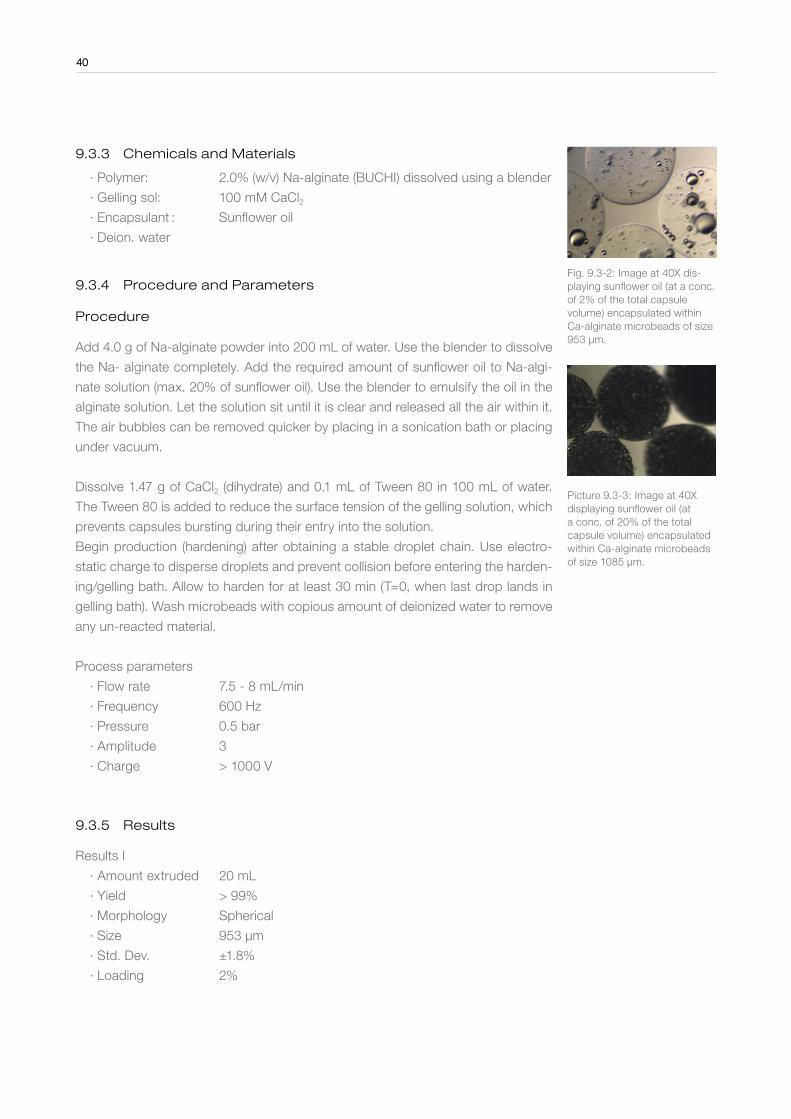
9 .3 .5 Results
Results I
∙ Amount extruded 20 mL
∙ Yield > 99%
∙ Morphology Spherical
∙ Size 953 µm
∙ Std. Dev. ±1.8%
∙ Loading 2%
Fig. 9.3-2: Image at 40X dis-playing sunflower oil (at a conc. of 2% of the total capsule volume) encapsulated within Ca-alginate microbeads of size 953 µm.
Picture 9.3-3: Image at 40X displaying sunflower oil (at a conc. of 20% of the total capsule volume) encapsulated within Ca-alginate microbeads of size 1085 µm.
40

41
Results II
∙ Amount extruded 20 mL
∙ Yield > 99%
∙ Morphology Spherical
∙ Size 1085 µm
∙ Std. Dev. 4.5%
∙ Loading 20%
9 .3 .6 Conclusion
The method of encapsulating (emulsified) oil into a Ca-alginate matrix is possible
with various concentrations of oil (recommended ≤ 20% of oil). With the different
nozzle sizes available for the Encapsulator the particle size can be chosen in the
range of 150 - 2000 µm.
9 .3 .7 References
[1] Whelehan and Marison (2011). Microencapsulation using vibrating technology.
Journal of Microencapsulation 28:669-68.
41
42
9 .4 Production of hard fat capsules
Encapsulator B-390: Encapsulation of water and water-soluble materials within
hard-fat based capsules
9 .4 .1 Introduction
Long chain triglycerides can be employed as a unique structural material to pro-
duce beads and capsules for the successful encapsulation and retention of water
and water-soluble materials. At temperatures below 40 °C these fats form solid
structures which can entrap the material present. Above these temperatures the
solid fats melt and release the encapsulated material.
The advantage of this method is that it is able to encapsulate hydrophilic substances.
The following example substances can be encapsulated using this method:
∙ Perfume oils
∙ Detergents
∙ Cosmetics
∙ APIs (hydrophilic and hydrophobic)
∙ Vitamins and minerals
∙ Flavors and fragrances
∙ Bioactive materials
∙ Many other aqueous based materials
This method enables the encapsulated substance (termed encapsulant) to be pro-
tected from many different environmental conditions such as oxygen, heat, pH
etc., and can help prolong its shelf life. In addition encapsulation also enables the
controlled release of the encapsulant.
9 .4 .2 Equipment
∙ Instrument: Encapsulator B-390
∙ Set up: Concentric nozzle system: Shell 300 µm & core nozzle 150 µm
∙ Pumping: Air pressure
9 .4 .3 Chemicals and Materials
∙ Polymer: Vegetal fat
∙ Gelling sol: Ethanol maintained at 10 °C
∙ Encapsulant: Water
∙ Deionized water
42

43
9 .4 .4 Procedure and Parameters
Melt 200 g of fat with a heating plate and keep the fat at 55 °C.
Switch on the nozzle heater of the Encapsulator B-390 and set it to 60 °C. Wait
until the nozzle has reached the temperature.
Pump the liquidized fat solution through the heated shell nozzle to form a liquid jet
which is broken up into droplets by the vibrational frequency. The fat solution can
be maintained at a temperature of 55 °C by placing the solution on a hot plate with
magnetic stirring. After obtaining a stable droplet chain with the shell material, the
pumping of the water through the core nozzle should begin. Slight adjustment (to
the set up values) of both flow rates will be required to obtain a stable chain of mo-
no-centric droplets.
The distance between the tip of the nozzle and the surface of the cooling ethanol
should be at least 50 cm to allow the fat-based shell of the droplet to cool enough
before landing in the cooling ethanol, otherwise the droplet will lose its spheri-
cal shape. The distance between the surface and bottom of the cooling solution
should also be at least 30 cm to allow the bead to harden sufficiently before hitting
the bottom of the vessel. Allow to harden for 30 minutes in the ethanol and make
sure this liquid remains below 10°C during production process. After production
remove excess ethanol by filtration.
Note: Ethanol was chosen as the hardening solution as its density is lower than
that of the fat material used in this study. This ensures that the produced cap-
sules sink to the bottom of the vessel after entering. This prevents incoming drop-
lets from colliding with these particles, which may occur if capsules float on top of
the surface, hence enabling the production of spherical and mono-disperse cap-
sules. Produced capsules should be stored under 30°C to prevent any melting and
sticking.
Process parameters
∙ Flow rate 6-8 (shell) & 0.5 - 1 (core) mL/min
∙ Frequency 500 - 700 Hz
∙ Pressure 0.5 bar
∙ Amplitude 3
∙ Charge > 2000 V
9 .4 .5 Results
∙ Yield of aq. liquid > 95%
∙ Morphology Spherical
∙ Loading 15%
Figure 9.4-1: Image displaying the produced capsules contain-ing a water core surrounded by a hard fat membrane. The cap-sules have a size of between 550 to 800 µm.
43
44
9 .4 .6 Conclusion
The formation of hard fat based microcapsules for the encapsulation of water and other
aqueous based liquids can be performed using the Encapsulator B-390 due to the
temperature controlled nozzle, which helps maintain the temperature above the solidi-
fication point of the fat. The loading of the core material within the capsules can be up
to 30%. With the different nozzle sizes available for the Encapsulator the capsule size
can be chosen in the range of 400 - 2200 µm.
9 .4 .7 References
This application was developed in-house by BÜCHI Labortechnik AG. For more infor-
mation please contact www.buchi.com.
44
9 .5 Producing large Ca-alginate microbeads
Encapsulator B-390/B-395 Pro: Production of large Ca-alginate micro-beads with
a size of > 1500 µm
9 .5 .1 Introduction
Ca-alginate micro-beads can be used to encapsulate various kinds of materials.
This method enables the encapsulated substance (termed encapsulant) to be pro-
tected from many different environmental conditions such as oxygen, heat, pH
etc., and can help prolong its shelf life.
The following example substances can be encapsulated using this method:
∙ Cells (yeast, bacteria and animal cells)
∙ APIs (hydrophobic)
∙ Essential oils & hydrophobic liquids
∙ Flavors & fragrances
∙ Vitamins & minerals
∙ Bioactive materials
∙ Enzymes
∙ Detergents
∙ Cosmetics
Aim: To produce Ca-alginate microbeads using the Encapsulator B-390/B-395 Pro
with a size > 1500 µm.
General rule: Final micro-bead diameter is roughly twice the size of the selected
nozzle size.
9 .5 .2 Equipment
∙ Instrument: Encapsulator B-390/B-395 Pro
∙ Set up: Single nozzle system – 1000 µm nozzle
∙ Pumping: Syringe pump/air pressure system
∙ Blender: Any kind of blender can be used
9 .5 .3 Chemicals and Materials
∙ Polymer: 2% (w/v) Na-alginate (BUCHI)
∙ Gelling sol: 100 mM CaCl2
∙ Deion. water
45
Figure 9.5-2: Microscopic image at 40X displaying the Ca-alginate micro-beads produced by the BUCHI Encapsulator B-390 using the described procedure.
Figure 9.5-3: Digital camera image displaying the produced Ca-alginate micro-beads.

46
9 .5 .4 Procedure and Parameters
Remove pre-filter from bead producing unit. Add 4.0 g of Na-alginate powder into 200
mL of water. Use the blender to dissolve the Na- alginate completely (Fig. 9.5-1). Let
the solution sit until it is clear and has released all the air within it. The air bubbles can
be removed quicker by placing in a sonication bath or placing under vacuum.
Begin production (hardening) after obtaining a stable droplet chain. Use electrostatic
charge to disperse droplets and prevent collision (coalescence) before they enter the
gelling bath. Deliver 50 mL of alginate through nozzle into gelling bath. Allow to harden
for 30 min (T=0 when last drop lands in gelling bath). Wash the beads with plenty of
water.
Process parameters
∙ Flow rate 30 - 35 mL/min
∙ Frequency 50 - 70 Hz
∙ Pressure 0.5 bar
∙ Amplitude 9
∙ Charge > 2000 V
9 .5 .5 Results
∙ Amount extruded 32 mL
∙ Yield > 99%
∙ Morphology Spherical
∙ Size 1870 µm
∙ Std. Dev. ± 5.2%
9 .5 .6 Conclusion
Due to the parameters employed, very large droplets are produced using this proce-
dure. These large particles can be observed in the strobe light during jet break up.
In most cases the electrostatic charge employed will not be able to disperse the drop-
lets in the chain due to their large size. On the other hand it will help stabilize the drops
in the chain, which will prevent coalescence occurring. After turning on the charge the
jet will appear to be deflected off center, however this is very common occurrence and
is due to the applied charge. This deflection is helpful in obtaining mono-dispersed
particles of equal size and shape.
9 .5 .7 References
This application was developed in-house by BÜCHI Labortechnik AG. For more infor-
mation please contact www.buchi.com.
46
47
9 .6 Producing cellulose sulphate microcapsules
Encapsulator B-390/B-395 Pro: Production of cellulose sulphate-polyDADMAC
microcapsules for application within medical, biotech and pharmaceutical fields
9 .6 .1 Introduction
Cellulose sulphate is a biocompatible ester and microcapsules are obtained by
dripping solutions of the polymer into a precipitation bath containing the synthetic
polycation poly diallydimethylammonium chloride (polyDADMAC). This results in a
rapid electrostatic interaction at the interface between the two oppositely charged
polymers, cumulating in the formation of a mechanically stable hydrogel mem-
brane in a single step process. These microcapsules have excellent mechanical
properties due to strongly interacting sulphate groups and do not initiate immune
response. In addition membranes have a homogenous structure and a narrow
pore size, and the latter can be pre-determined.
The method is mainly used for the encapsulation of animal and stem cells for medi-
cal and biotechnological applications, and has being used in clinical trials for trans-
plantation of cells within humans to treat many diseases. It can also be used for
encapsulating API’s.
Aim: To produce cellulose sulphate-polyDADMAC microcapsules using a single
step process compared to other cell encapsulation process (alginate-poly-L-lysine)
which require multiply steps.
9 .6 .2 Equipment
∙ Product: Encapsulator B-390/B-395 Pro
∙ Set up: Single-flow nozzle system – 300 µm nozzle
∙ Pumping: Syringe pump/air pressure system
∙ Blender
9 .6 .3 Chemicals and Materials
∙ Polymer: 2% (w/v) Cellulose sulphate (Biorefinary, Germany)
∙ Gelling sol: 4% PolyDADMAC (Mw 35 kDa) (Biorefinary, Germany)
∙ Deion. water
9 .6 .4 Procedure and Parameters
Remove pre-filter from bead producing unit.
Dissolve 2 g of cellulose-sulphate in 100 mL of water. Use the blender to dissolve
the cellulose sulphate completely. Let the solution sit until it is clear and has re-
leased all the air within it. The air bubbles can be removed quicker by placing in a
sonication bath or placing under vacuum.
47
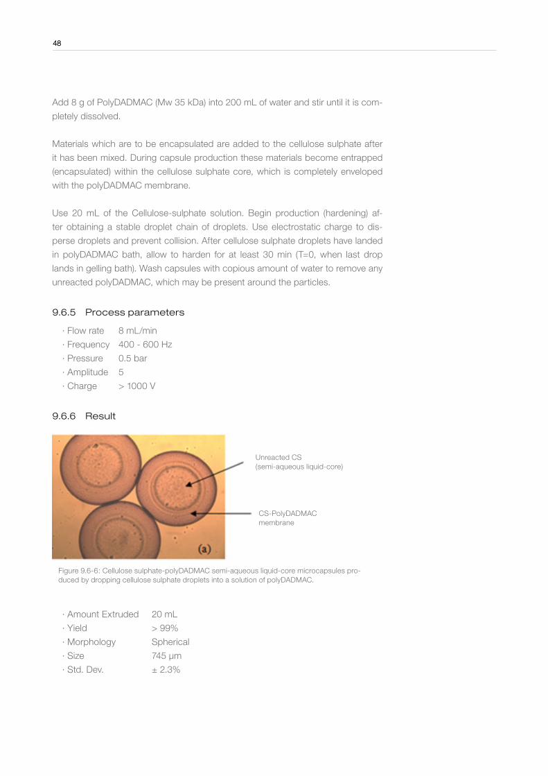
48
Add 8 g of PolyDADMAC (Mw 35 kDa) into 200 mL of water and stir until it is com-
pletely dissolved.
Materials which are to be encapsulated are added to the cellulose sulphate after
it has been mixed. During capsule production these materials become entrapped
(encapsulated) within the cellulose sulphate core, which is completely enveloped
with the polyDADMAC membrane.
Use 20 mL of the Cellulose-sulphate solution. Begin production (hardening) af-
ter obtaining a stable droplet chain of droplets. Use electrostatic charge to dis-
perse droplets and prevent collision. After cellulose sulphate droplets have landed
in polyDADMAC bath, allow to harden for at least 30 min (T=0, when last drop
lands in gelling bath). Wash capsules with copious amount of water to remove any
unreacted polyDADMAC, which may be present around the particles.
9 .6 .5 Process parameters
∙ Flow rate 8 mL/min
∙ Frequency 400 - 600 Hz
∙ Pressure 0.5 bar
∙ Amplitude 5
∙ Charge > 1000 V
9 .6 .6 Result
CS-PolyDADMAC membrane
Unreacted CS (semi-aqueous liquid-core)
Figure 9.6-6: Cellulose sulphate-polyDADMAC semi-aqueous liquid-core microcapsules pro-duced by dropping cellulose sulphate droplets into a solution of polyDADMAC.
∙ Amount Extruded 20 mL
∙ Yield > 99%
∙ Morphology Spherical
∙ Size 745 µm
∙ Std. Dev. ± 2.3%
48

49
9 .6 .7 Conclusion
The Encapsulator B-390 and B-395 Pro are able to produce spherical cellulose sulphate-polyDADMAC microcapsules in a single step process with the produced particles having an extremely narrow size distribution. These capsules can also be produced under sterile conditions by using the reaction vessel of the B-395 Pro for encapsulation of animal and stem cells for bio-medical applications.
Many studies have shown that these types of capsules function more optimally
compared to alginate-poly-L-lysine capsules system as they do not initiate immune
response and form a more stable structure.
With the different nozzle sizes available for the Encapsulator the cellulose sulphate
capsule size can be chosen in the range of 400 - 2500 µm and capsule size can
also be varied by using different molecular weight polyDADMAC.
9 .6 .8 References
Dautzenberg, H. et al. (1999). Development of cellulose sulphate-based polyelec-
trolyte complex microcapsules for medical applications, P. 46-63. In D. Hunkeler,
et al., (Ed). Bioartifical Organs II: Technology, Medicine and Materials. New York
Acad Sciences, New York (1999).
49
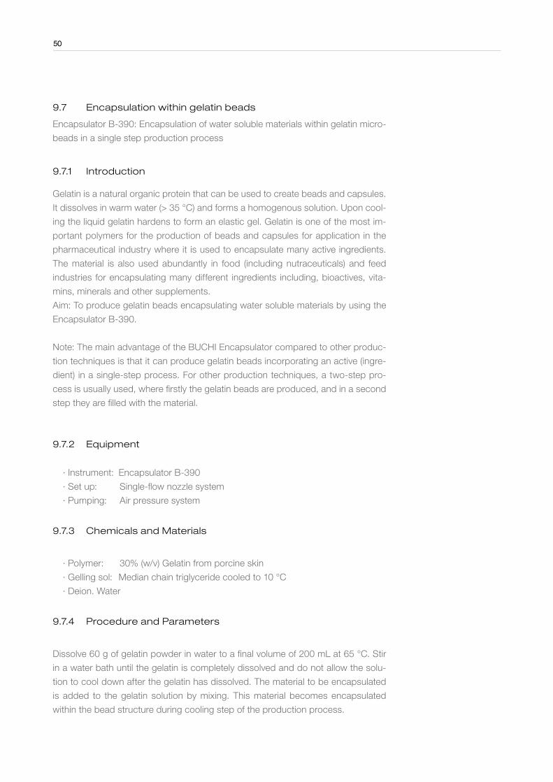
50
9 .7 Encapsulation within gelatin beads
Encapsulator B-390: Encapsulation of water soluble materials within gelatin micro-
beads in a single step production process
9 .7 .1 Introduction
Gelatin is a natural organic protein that can be used to create beads and capsules.
It dissolves in warm water (> 35 °C) and forms a homogenous solution. Upon cool-
ing the liquid gelatin hardens to form an elastic gel. Gelatin is one of the most im-
portant polymers for the production of beads and capsules for application in the
pharmaceutical industry where it is used to encapsulate many active ingredients.
The material is also used abundantly in food (including nutraceuticals) and feed
industries for encapsulating many different ingredients including, bioactives, vita-
mins, minerals and other supplements.
Aim: To produce gelatin beads encapsulating water soluble materials by using the
Encapsulator B-390.
Note: The main advantage of the BUCHI Encapsulator compared to other produc-
tion techniques is that it can produce gelatin beads incorporating an active (ingre-
dient) in a single-step process. For other production techniques, a two-step pro-
cess is usually used, where firstly the gelatin beads are produced, and in a second
step they are filled with the material.
9 .7 .2 Equipment
∙ Instrument: Encapsulator B-390
∙ Set up: Single-flow nozzle system
∙ Pumping: Air pressure system
9 .7 .3 Chemicals and Materials
∙ Polymer: 30% (w/v) Gelatin from porcine skin
∙ Gelling sol: Median chain triglyceride cooled to 10 °C
∙ Deion. Water
9 .7 .4 Procedure and Parameters
Dissolve 60 g of gelatin powder in water to a final volume of 200 mL at 65 °C. Stir
in a water bath until the gelatin is completely dissolved and do not allow the solu-
tion to cool down after the gelatin has dissolved. The material to be encapsulated
is added to the gelatin solution by mixing. This material becomes encapsulated
within the bead structure during cooling step of the production process.
50

51
Switch on the nozzle heater of the Encapsulator B-390 and set it to 70 °C and
wait until it heats up. Place the medium chain triglyceride (cooling oil) into a bea-
ker, precool to 10 °C and maintain at this temperature during production. The oil
is used to catch and cool the warm gelatin droplets and produce gelled elastic
beads. Pump the gelatin solution, which is kept at 60 – 65 °C (by placing the bot-
tle containing the solution into a water bath), through the heated nozzle to form a
liquid jet, which is broken up into droplets by the vibrational frequency. The pro-
duced droplets will land into the cooling oil bath below which should be agitated at
a high speed (vortex size > 2 cm) using a magnetic stirrer. The distance between
the surface and bottom of the cooling oil should be at least 10 cm to allow the
gelatin bead to harden sufficiently before hitting the bottom of the vessel used to
hold the cooling oil.
Allow the gelatin beads to harden for 30 min in the cooling oil and make sure this
liquid remains below 10 °C during the production process. Remove excess oil by
filtering and/or with a paper towel. The gelatin beads can be either dried over a pe-
riod of 24 - 48 h by leaving to air dry at ambient conditions or within 8 - 24 h using
a BUCHI Rotavapor to evaporate the water. During the beads should be constant-
ly rotated to prevent sticking and clumping.
9 .7 .5 Process parameters
∙ Nozzle size 1000 µm
∙ Flow rate 30 - 35 mL/min
∙ Frequency 40 Hz
∙ Pressure 0.4 – 0.7 bar
∙ Amplitude 9
∙ Charge ≥ 2000 V
51
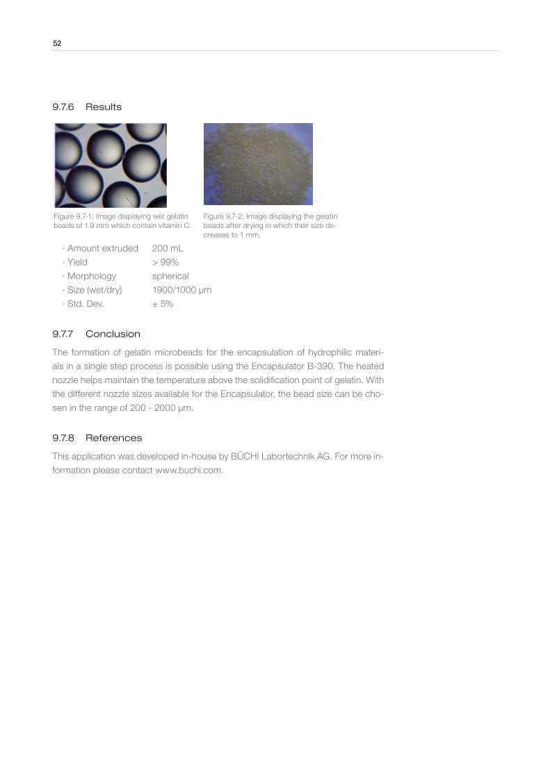
52
9 .7 .6 Results
Figure 9.7-1: Image displaying wet gelatin beads of 1.9 mm which contain vitamin C.
Figure 9.7-2: Image displaying the gelatin beads after drying in which their size de-creases to 1 mm.
∙ Amount extruded 200 mL
∙ Yield > 99%
∙ Morphology spherical
∙ Size (wet/dry) 1900/1000 µm
∙ Std. Dev. ± 5%
9 .7 .7 Conclusion
The formation of gelatin microbeads for the encapsulation of hydrophilic materi-
als in a single step process is possible using the Encapsulator B-390. The heated
nozzle helps maintain the temperature above the solidification point of gelatin. With
the different nozzle sizes available for the Encapsulator, the bead size can be cho-
sen in the range of 200 - 2000 µm.
9 .7 .8 References
This application was developed in-house by BÜCHI Labortechnik AG. For more in-
formation please contact www.buchi.com.
52
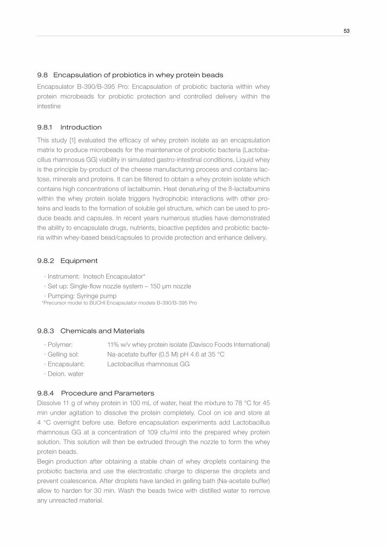
53
9 .8 Encapsulation of probiotics in whey protein beads
Encapsulator B-390/B-395 Pro: Encapsulation of probiotic bacteria within whey
protein microbeads for probiotic protection and controlled delivery within the
intestine
9 .8 .1 Introduction
This study [1] evaluated the efficacy of whey protein isolate as an encapsulation
matrix to produce microbeads for the maintenance of probiotic bacteria (Lactoba-
cillus rhamnosus GG) viability in simulated gastro-intestinal conditions. Liquid whey
is the principle by-product of the cheese manufacturing process and contains lac-
tose, minerals and proteins. It can be filtered to obtain a whey protein isolate which
contains high concentrations of lactalbumin. Heat denaturing of the ß-lactalbumins
within the whey protein isolate triggers hydrophobic interactions with other pro-
teins and leads to the formation of soluble gel structure, which can be used to pro-
duce beads and capsules. In recent years numerous studies have demonstrated
the ability to encapsulate drugs, nutrients, bioactive peptides and probiotic bacte-
ria within whey-based bead/capsules to provide protection and enhance delivery.
9 .8 .2 Equipment
∙ Instrument: Inotech Encapsulator*
∙ Set up: Single-flow nozzle system – 150 µm nozzle
∙ Pumping: Syringe pump *Precursor model to BUCHI Encapsulator models B-390/B-395 Pro
9 .8 .3 Chemicals and Materials
∙ Polymer: 11% w/v whey protein isolate (Davisco Foods International)
∙ Gelling sol: Na-acetate buffer (0.5 M) pH 4.6 at 35 °C
∙ Encapsulant: Lactobacillus rhamnosus GG
∙ Deion. water
9 .8 .4 Procedure and Parameters
Dissolve 11 g of whey protein in 100 mL of water, heat the mixture to 78 °C for 45
min under agitation to dissolve the protein completely. Cool on ice and store at
4 °C overnight before use. Before encapsulation experiments add Lactobacillus
rhamnosus GG at a concentration of 109 cfu/ml into the prepared whey protein
solution. This solution will then be extruded through the nozzle to form the whey
protein beads.
Begin production after obtaining a stable chain of whey droplets containing the
probiotic bacteria and use the electrostatic charge to disperse the droplets and
prevent coalescence. After droplets have landed in gelling bath (Na-acetate buffer)
allow to harden for 30 min. Wash the beads twice with distilled water to remove
any unreacted material.
53
54
9 .8 .5 Process parameters
∙ Flow rate 2.3 - 2.8 mL/min
∙ Frequency 800 - 1800 Hz
∙ Pressure 0.5 bar
∙ Amplitude 1 - 3
∙ Charge 1500 V
9 .8 .6 Results
The production of mono-dispersed whey protein microbeads encapsulating probi-
otic bacteria was developed in this work [1]. Optimization of encapsulation condi-
tions generated self-supporting microbead structures (200 ± 1.2 µm) with an indi-
vidual loading capacity of 2.7 x 10⁴ cfu / microbead. The most stable structures
were obtained within the acetate buffer at pH 4.6.
9 .8 .7 Conclusion
In this study [1] it was demonstrated that the technique employed had no detri-
mental effect on cell viability during bead production. Following production the
probiotic-containing microbeads were incubated under simulated gastro-intestinal
conditions. It was subsequently shown that incubation of the microbeads under
conditions associated with the stomach (pH 1.8; 37 °C) demonstrated acid-sta-
bility and peptic-resistance of the beads, which helped maintain viability of the
encapsulated bacteria under these conditions. However incubation under intesti-
nal conditions resulted in the rapid breakdown (due to enzyme activated intestinal
conditions) of the bead structure, hence enabling the controlled release of the pro-
biotic bacteria into the surrounding environment.
9 .8 .8 References
[1] Doherty S.B., et. al. (2011). Development and characterization of whey protein
micro-beads as potential matrices for probiotic protection. Food Hydrocolloids
25:1604-1617.
54
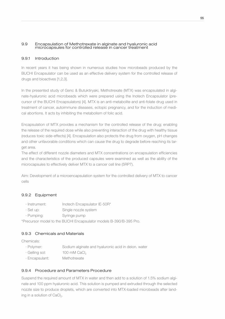
55
9 .9 Encapsulation of Methotrexate in alginate and hyaluronic acid microcapsules for controlled release in cancer treatment
9 .9 .1 Introduction
In recent years it has being shown in numerous studies how microbeads produced by the
BUCHI Encapsulator can be used as an effective delivery system for the controlled release of
drugs and bioactives [1,2,3].
In the presented study of Genc & Butuktiryaki, Methotrexate (MTX) was encapsulated in algi-
nate-hyaluronic acid microbeads which were prepared using the Inotech Encapsulator (pre-
cursor of the BUCHI Encapsulators) [4]. MTX is an anti-metabolite and anti-folate drug used in
treatment of cancer, autoimmune diseases, ectopic pregnancy, and for the induction of medi-
cal abortions. It acts by inhibiting the metabolism of folic acid.
Encapsulation of MTX provides a mechanism for the controlled release of the drug; enabling
the release of the required dose while also preventing interaction of the drug with healthy tissue
(reduces toxic side-effects) [4]. Encapsulation also protects the drug from oxygen, pH changes
and other unfavorable conditions which can cause the drug to degrade before reaching its tar-
get area.
The effect of different nozzle diameters and MTX concentrations on encapsulation efficiencies
and the characteristics of the produced capsules were examined as well as the ability of the
microcapsules to effectively deliver MTX to a cancer cell line (5RP7).
Aim: Development of a microencapsulation system for the controlled delivery of MTX to cancer
cells
9 .9 .2 Equipment
∙ Instrument: Inotech Encapsulator IE-50R*
∙ Set up: Single nozzle system
∙ Pumping: Syringe pump
*Precursor model to the BUCHI Encapsulator models B-390/B-395 Pro.
9 .9 .3 Chemicals and Materials
Chemicals:
∙ Polymer: Sodium alginate and hyaluronic acid in deion. water
∙ Gelling sol: 100 mM CaCl2 ∙ Encapsulant: Methotrexate
9 .9 .4 Procedure and Parameters Procedure
Suspend the required amount of MTX in water and then add to a solution of 1.5% sodium algi-
nate and 100 ppm hyaluronic acid. This solution is pumped and extruded through the selected
nozzle size to produce droplets, which are converted into MTX-loaded microbeads after land-
ing in a solution of CaCl2.
55
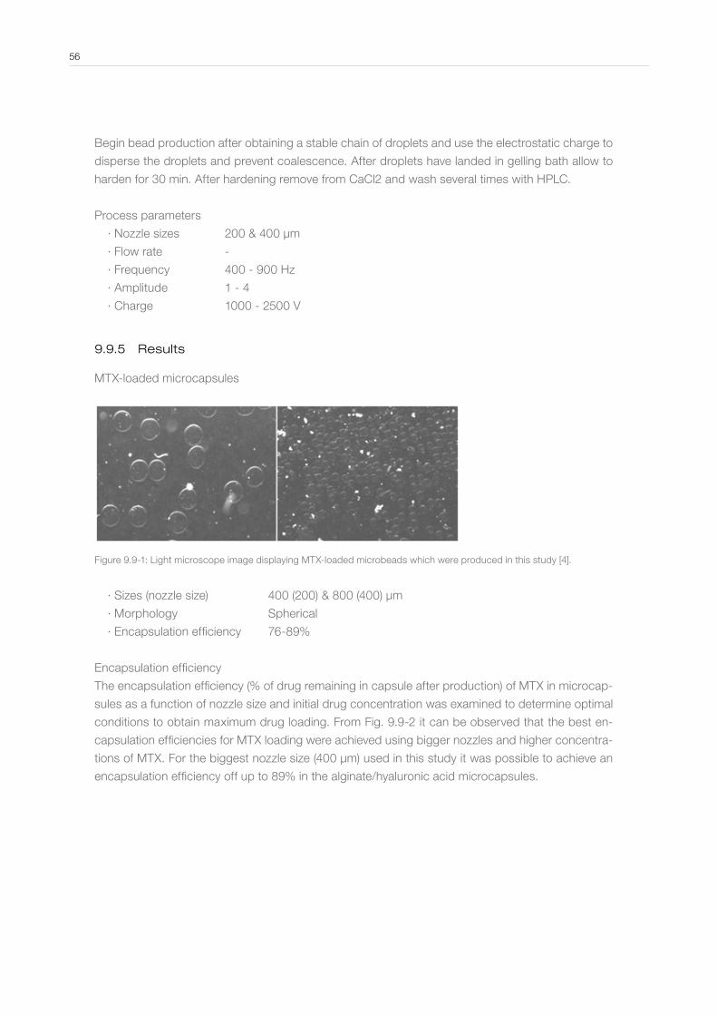
Begin bead production after obtaining a stable chain of droplets and use the electrostatic charge to
disperse the droplets and prevent coalescence. After droplets have landed in gelling bath allow to
harden for 30 min. After hardening remove from CaCl2 and wash several times with HPLC.
Process parameters
∙ Nozzle sizes 200 & 400 µm
∙ Flow rate -
∙ Frequency 400 - 900 Hz
∙ Amplitude 1 - 4
∙ Charge 1000 - 2500 V
9 .9 .5 Results
MTX-loaded microcapsules
Figure 9.9-1: Light microscope image displaying MTX-loaded microbeads which were produced in this study [4].
∙ Sizes (nozzle size) 400 (200) & 800 (400) µm
∙ Morphology Spherical
∙ Encapsulation efficiency 76-89%
Encapsulation efficiency
The encapsulation efficiency (% of drug remaining in capsule after production) of MTX in microcap-
sules as a function of nozzle size and initial drug concentration was examined to determine optimal
conditions to obtain maximum drug loading. From Fig. 9.9-2 it can be observed that the best en-
capsulation efficiencies for MTX loading were achieved using bigger nozzles and higher concentra-
tions of MTX. For the biggest nozzle size (400 µm) used in this study it was possible to achieve an
encapsulation efficiency off up to 89% in the alginate/hyaluronic acid microcapsules.
56
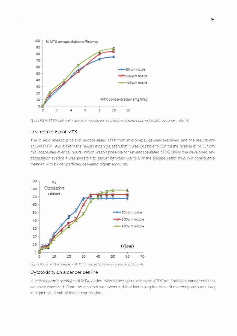
57
Figure 9.9-2. MTX-loading efficiencies in microbeads as a function of nozzle size and initial drug concentration [4].
In vitro release of MTX
The in vitro release profile of encapsulated MTX from microcapsules was examined and the results are
shown in Fig. 9.9-3. From the results it can be seen that it was possible to control the release of MTX from
microcapsules over 30 hours, which wasn’t possible for un-encapsulated MTX. Using the developed en-
capsulation system it was possible to deliver between 68-79% of the encapsulated drug in a controllable
manner, with bigger particles delivering higher amounts.
Figure 9.9-3. In vitro release of MTX from microcapsules as a function of size [4].
Cytotoxicity on a cancer cell line
In vitro cytotoxicity effects of MTX-loaded microbeads formulations on 5RP7 (rat fibroblast cancer cell line)
was also examined. From the results it was observed that increasing the dose of microcapsules resulting
in higher cell death of the cancer cell line.
57
9 .9 .6 Conclusion
This study has shown how microencapsulation can be used to control the release
of MTX to cancerous cells and reduce its toxic effect on healthy tissue. Using the
microcapsule system developed on the Encapsulator it was possible to obtain an
MTX encapsulation efficiency of up to 89% while also effectively controlling the re-
lease rate of the drug from the microbeads over a 30 h period. In cell culture stud-
ies delivery of the encapsulated MTX reduced cancer cell viability by up to 88.5%
compared to 49.7% for un-encapsulated MTX.
9 .9 .7 References
[1] Doherty S.B., et. al. (2011). Development and characterization of whey protein
micro-beads as potential matrices for probiotic protection. Food Hydrocolloids
25:1604-1617.
[2] Dorati, R et. al. (2013). Microencapsulation of a hydrophilic model molecule
through Vibration nozzle and emulsion phase inversion technologies 30(6):559-570.
[3] Hoad, C. (2011) Encapsulation of lipid by alginate beads reduces bio-accessi-
bility: An in vivo 13C breath test and MRI study. Food Hydrocolloids 25:1190-1200.
[4] Genc, L. & Butuktiryaki S (2014). Preparation and characterization of metho-
trexate-loaded microcapsules. Pharmaceutical development & technology 19(1):
42-47.
58

AcknowledgmentsThe author would like to express his gratitude his colleagues Philipp John, Marco Meuri, Dr. Raphael Plüss, Dr. David Rütti and Dr. Simon Diezi for their invaluable inputs, suggestions and proof-reading of the manuscript. Additional thanks are conveyed to Dr. Raphael Plüss and Dr. David Rütti for their scientific input and expertise. Christophe Waeber and Sanami Bruderer from BUCHI Global Communi-cations department are acknowledged for preparing the printed version of the manuscript.
Dr. Micheal Whelehan
ImprintAuthor Dr. Micheal WhelehanPublisher BÜCHI Labortechnik AG, CH-9230, Flawil, SwitzerlandCopyright © 2014 by BÜCHI Labortechnik AG, CH-9230, Flawil, Switzerland
Quality in your hands
BUCHI Affiliates:
We are represented by more than 100 distribution partners worldwide . Find your local representative at: www .buchi .com
BÜCHI Labortechnik AGCH – 9230 Flawil 1T +41 71 394 63 63F +41 71 394 65 [email protected]
BÜCHI Labortechnik GmbHDE – 45127 EssenFreecall 0800 414 0 414T +49 201 747 490F +49 201 747 492 0 [email protected]
BUCHI SarlFR – 94656 Rungis CedexT +33 1 56 70 62 50F +33 1 46 86 00 [email protected]
BUCHI Italia s .r .l .IT – 20010 Cornaredo (MI)T +39 02 824 50 11F +39 02 57 51 28 [email protected]
BÜCHI Labortechnik GmbHBranch Offi ce BeneluxNL – 3342 GT Hendrik-Ido-AmbachtT +31 78 684 94 29F +31 78 684 94 30 [email protected]
BUCHI UK Ltd .GB – Oldham OL9 9QLT +44 161 633 1000F +44 161 633 [email protected]
BUCHI Russia/CISUnited Machinery AGRU – 127787 Moscow T +7 495 36 36 495F +7 495 981 05 [email protected]
BUCHI ChinaCN – 200052 ShanghaiT +86 21 6280 3366F +86 21 5230 [email protected]
BUCHI (Thailand) Ltd . TH – Bangkok 10600T +66 2 862 08 51F +66 2 862 08 [email protected]
Nihon BUCHI K .K . JP – Tokyo 110-0008 T +81 3 3821 4777F +81 3 3821 [email protected]
BUCHI India Private Ltd .IN – Mumbai 400 055 T +91 22 667 75400F +91 22 667 [email protected] www.buchi.in
PT . BUCHI IndonesiaID – Tangerang 15321T +62 21 537 62 16F +62 21 537 62 [email protected]
BUCHI Korea IncKR – Seoul 153-782T +82 2 6718 7500F +82 2 6718 [email protected]
BUCHI CorporationUS – New Castle, Delaware 19720Toll Free: +1 877 692 8244T +1 302 652 3000F +1 302 652 [email protected] BUCHI do BrasilBR – Valinhos SP 13271-570T +55 19 3849 1201F +41 71 394 65 [email protected]
BUCHI Support Centers:South East Asia
BUCHI (Thailand) Ltd .TH-Bangkok 10600T +66 2 862 08 51F +66 2 862 08 [email protected]
Latin America
BUCHI Latinoamérica Ltda .BR – Valinhos SP 13271-570T +55 19 3849 1201F +41 71 394 65 [email protected]
Middle East
BUCHI Labortechnik AGUAE – Dubai T +971 4 313 2860F +971 4 313 [email protected]
BÜCHI NIR-Online
DE – 69190 Walldorf T +49 6227 73 26 60F +49 6227 73 26 [email protected]
11595052 en 1408 A /Technical data are subject to change without notice/Quality Systems ISO 9001.The English version is the original language version and serves as basis for all translations into other languages.