Enabling Techniques for LTE-A and beyondprojects.celtic-initiative.org/winner+/WINNER+...
60
Page 1 (60) Project Number: CELTIC / CP5-026 Project Title: Wireless World Initiative New Radio – WINNER+ Document Type: PU Document Identifier: D2.2 Document Title: Enabling Techniques for LTE-A and beyond Source Activity: WP2 Editor: Afif Osseiran Authors: Gunther Auer, Mehdi Bennis, Mauro Boldi, Alexandre Gouraud, Volker Jungnickel, Sylvie Mayrargue, Albena Mihovska, Jose F. Monserrat, Afif Osseiran, Pawel Sroka,Tommy Svensson, Antti Tölli, Jaakko Vihriälä, Lars Thiele, Eric Zinovieff Status / Version: 1.0 Date Last changes: 06.07.10 File Name: D2.2.doc Abstract: This deliverable summarizes the most promising enabling techniques for LTE-A and beyond in seven major areas. These areas are: Carrier Aggregation, Coordinated Multipoint Systems, Femtocells, Network Coding, MIMO, Quality of Service, Resource allocation, and Relaying. A description of the most relevant scenarios where the techniques can be used is given. Further the end-2-end performance approach is presented. Finally future research directions of enabling techniques beyond LTE-A are given. Keywords: Carrier Aggregation, Coordinated Multipoint Systems, End-2-End Performance, Femtocells, Network Coding, MIMO, Quality of Service, Resource allocation, Relaying, Scenarios, Spectrum Technologies, IMT Advanced and beyond. Disclaimer:
Transcript of Enabling Techniques for LTE-A and beyondprojects.celtic-initiative.org/winner+/WINNER+...

Page 1 (60)
Project Number: CELTIC / CP5-026
Project Title: Wireless World Initiative New Radio – WINNER+
Document Type: PU
Document Identifier:
D2.2
Document Title: Enabling Techniques for LTE-A and beyond Source Activity: WP2
Editor: Afif Osseiran
Authors:
Gunther Auer, Mehdi Bennis, Mauro Boldi, Alexandre Gouraud, Volker Jungnickel, Sylvie Mayrargue, Albena Mihovska, Jose F. Monserrat, Afif Osseiran, Pawel Sroka,Tommy Svensson, Antti Tölli, Jaakko Vihriälä, Lars Thiele, Eric Zinovieff
Status / Version: 1.0
Date Last changes:
06.07.10
File Name: D2.2.doc
Abstract:
This deliverable summarizes the most promising enabling techniques for LTE-A and beyond in seven major areas. These areas are: Carrier Aggregation, Coordinated Multipoint Systems, Femtocells, Network Coding, MIMO, Quality of Service, Resource allocation, and Relaying. A description of the most relevant scenarios where the techniques can be used is given. Further the end-2-end performance approach is presented. Finally future research directions of enabling techniques beyond LTE-A are given.
Keywords:
Carrier Aggregation, Coordinated Multipoint Systems, End-2-End Performance, Femtocells, Network Coding, MIMO, Quality of Service, Resource allocation, Relaying, Scenarios, Spectrum Technologies, IMT Advanced and beyond.
Disclaimer:

WINNER+ D2.2
Version: 1.0 Page 2 (60)
Executive Summary In WINNER+, the overwhelming innovations for IMT-Advanced and beyond were generated by work package 1 (WP1). The exhaustive list of these innovations appeared in deliverable D1.9. Moreover work package 2 (WP2) has been responsible for checking the most promising set of these innovations and their compliance with LTE-Advanced. In particular this deliverable D2.2 is the final WP2 deliverable with threefold objective. The first is to promote the most promising techniques based on their performance, potentials, and compliance with standards. Secondly it aims at placing these selected innovations within the appropriate deployment/usage/user scenarios. Thirdly it paves the way for the future research directions for IMT-Advanced and beyond.
These innovations are categorized into the areas of Resource Allocation, Carrier Aggregation, Femtocells, Relaying, Network Coding, Multi-User Multiple-Input-Multiple-Output (MU-MIMO) systems and Channel State Information (CSI) acquisition, Quality of Service (QoS) control, and Coordinated Multipoint (CoMP).
Firstly the innovation techniques are classified within the framework of scenarios which allows better understanding and clarification under which circumstances such techniques fit best, and consequently can be used. The term ‘scenario’ is subdivided into several cases, namely the following: user scenario, usage scenario, traffic load scenario and deployment scenario.
Secondly, the selection of the innovations within each of the areas defined above is conducted.
In resource allocation which is a key factor influencing the system performance, the selected innovations deals with the Decentralised interference avoidance using Busy Burst, Spectrum sharing form game-theory perspective and Efficient MBMS.
In carrier Aggregation, the selection has been deeply assessed from different points of view; mainly from physical and MAC layers.
For the femtocells which is a promising method to increase system capacity, the revised femtocell innovations in WINNER+ are divided into two categories: coordinated and uncoordinated.
The relaying work carried out within the project has not allowed drawing a clear conclusion on the coverage and capacity improvements relays can bring in specific area of the network yet. However, it did help understanding the problems and concentrate on most important issues.
For network coding which is one of the favourable techniques for IMT-Advanced, the focus is on the uplink aspect using fixed relay nodes. Relay selection and user grouping in a relay multiple access scenario yields up to 70% gain in terms of system capacity.
In D2D communication which is also a very promising area. It is shown that in an ideal scenario where D2D communication is used as an underlay to an LTE network leads up to 7-fold increase in the cell throughput.
The Advanced Antenna innovations schemes focus mostly on seeking for system performance improvements from advances in the acquisition of CSIT – short term or long-term – via new signaling and estimation solutions. The preferred multi-antenna transmission methods both in rural/wide area and urban/local area scenarios with relatively low velocity are provided.
A number of innovations QoS have been developed; however these activities were focused on specific aspects, such as scheduling for mixes of different service classes. An interesting topic for further research would be to combine all these individual approaches into one holistic framework for QoS support.
In CoMP, extensive studies have been performed extensively within WINNER+. Those studies led to some relevant achievements and significant results in trial environments. A clear classification of CoMP modes has been proposed, identifying joint processing methods as very promising but somewhat complex and coordinated scheduling/beamforming as deployable initial compromise, with looser performances and complexity.
Finally the gaps in the WINNER+ research activities and other appealing are identified. These are the future directions that the WINNER+ consortium identified as necessary to end up with a complete definition of next generation mobile system.

WINNER+ D2.2
Version: 1.0 Page 3 (60)
Table of Contents
List of acronyms and abbreviations ............................................................... 7
1. Introduction.......................................................................................... 10
2. Scenarios ............................................................................................. 12 2.1 Background ..................................................................................................................................12
2.2 WINNER+ Innovations mapped to General and IMT-A-specific Requirements for Next Generation Systems................................................................................................................................13
2.2.1 General Requirements ........................................................................................................13
2.2.2 IMT-A Requirements .........................................................................................................14
2.2.3 Evaluation and Deployment Scenarios for WINNER + Innovations..................................15
2.3 Futuristic Scenario Approach.......................................................................................................15
3. WINNER+ Enabling Techniques ......................................................... 16 3.1 Resource Allocation .....................................................................................................................16
3.1.1 Resource allocation in LTE and LTE-Advanced................................................................16
3.1.2 Resource allocation in WINNER+ .....................................................................................17
3.1.3 Advantages and disadvantages of the proposed techniques................................................19
3.1.4 Conclusions and future research.........................................................................................20
3.2 Carrier Aggregation .....................................................................................................................20
3.2.1 Introduction ........................................................................................................................20
3.2.2 Carrier Aggregation in WINNER+.....................................................................................20
3.2.3 Implications on signalling and architecture ........................................................................22
3.2.4 Research trends in WINNER+............................................................................................23
3.2.5 Other appealing topics ........................................................................................................23
3.3 Femtocells ....................................................................................................................................24
3.3.1 Introduction ........................................................................................................................24
3.3.2 Femtocells in 3GPP ............................................................................................................26
3.3.3 Uncoordinated femtocells...................................................................................................26
3.3.4 Coordinated femtocells.......................................................................................................27
3.3.5 Requirements on architecture, signalling and measurements .............................................27
3.3.6 Conclusions and Future Research.......................................................................................28
3.4 Relaying .......................................................................................................................................29
3.4.1 State-of-the-art....................................................................................................................29
3.4.2 Objective.............................................................................................................................29
3.4.3 Conclusion..........................................................................................................................31
3.5 Network Coding and Peer-2- Peer ..............................................................................................31
3.5.1 Network Coding & Peer-2- Peer in LTE-A and beyond....................................................32

WINNER+ D2.2
Version: 1.0 Page 4 (60)
3.5.2 Non Binary Network Coding in uplink relaying scenario: Network coding for multiple-user multiple-relay systems ................................................................................................................32
3.5.3 Network Coding for uplink relay-based wireless communication system..........................32
3.5.4 Peer to Peer Communications.............................................................................................33
3.5.5 Performance........................................................................................................................33
3.6 Multi-user MIMO Systems and CSI Acquisition.........................................................................33
3.6.1 Introduction ........................................................................................................................33
3.6.2 MU-MIMO Support in IMT-A Proposals ..........................................................................34
3.6.3 Selected Advanced Antenna Schemes and Applicable Scenarios ......................................35
3.6.4 Future research trends.........................................................................................................38
3.6.5 Conclusion..........................................................................................................................38
3.7 Quality of Service Control ...........................................................................................................38
3.7.1 Introduction ........................................................................................................................38
3.7.2 Scheduling of Mixed Service Classes.................................................................................40
3.7.3 Multi-User Resource Allocation Maximizing the Perceived Quality .................................40
3.7.4 Joint Resource Allocation and Admission Control.............................................................40
3.7.5 Relay-Capable Flow Management for QoS Scheduling .....................................................40
3.7.6 Compliance with LTE and beyond .....................................................................................40
3.7.7 Conclusions and Future Research.......................................................................................41
3.8 Coordinated Multipoint................................................................................................................41
3.8.1 Introduction ........................................................................................................................41
3.8.2 CoMP and 3GPP related standardization activities ............................................................41
3.8.3 CoMP scenario in WINNER+ ............................................................................................42
3.8.4 Selected techniques.............................................................................................................44
3.8.5 Initial CoMP trials in an indoor and outdoor deployment ..................................................46
3.8.6 Conclusions ........................................................................................................................48
4. End-To-End System Performance...................................................... 49
5. Future Directions................................................................................. 51 5.1 Classification of Further Research Topics ...................................................................................51
5.2 Identified Topics for Further Research ........................................................................................52
6. Conclusions ......................................................................................... 55
7. References ........................................................................................... 57
A. Simulation scenario for CoMP............................................................ 60

WINNER+ D2.2
Version: 1.0 Page 5 (60)
Authors
Partner Name Phone / Fax / e-mail
Aalborg University CTIF
Albena Mihovska Phone: +45 99408639
e-mail: [email protected]
CEA-LETI
Sylvie Mayrargue Phone: +33 (0)438786242
e-mail: [email protected]
DOCOMO
Gunther Auer Phone: +49(89)56824-219
e-mail: [email protected]
Chalmers University of Technology
Tommy Svensson Phone: +46 31 772 1823
e-mail: [email protected]
Ericsson AB
Afif Osseiran Fax: +46 10 717 57 20
e-mail: [email protected]
France Telecom
Alexandre Gouraud Phone: +33 1 45 29 42 88
e-mail:[email protected]
Eric Zinovieff Phone: +33 1 45 29 50 03
e-mail: [email protected]
iTEAM
Jose F. Monserrat Phone: +34 963877007
Fax:+34 963879583
e-mail: [email protected]
Nokia Siemens Networks Finland
Jaakko Vihriälä Phone: +358 50 5933 638
e-mail: [email protected]

WINNER+ D2.2
Version: 1.0 Page 6 (60)
Poznan University of Tech.
Pawel Sroka Phone: +48 61 665 3913
e-mail: [email protected]
Telecom Italia Lab
Mauro Boldi Phone: +39 011 228 7771
e-mail: [email protected]
University of Oulu
Antti Tölli Phone: +358 8 553 2986
e-mail: [email protected]
Mehdi Bennis Phone : +358 40 8241 742
e-mail : [email protected]
Fraunhofer Heinrich Hertz Institut
Lars Thiele Phone: +49 30 31002429
e-mail: [email protected]
Volker Jungnickel Phone: +49 30 31002768
e-mail: [email protected]

WINNER+ D2.2
Version: 1.0 Page 7 (60)
List of acronyms and abbreviations
3GPP 3rd Generation Partnership Project AAC Advanced Audio Coding AAS Advanced Antenna Systems AMC Adaptive Modulation and Coding APP Application ARRM Advanced Radio Resource Management AVC Advanced Video Coding BC BroadCast BE Best Effort B-IFDMA Block IFDMA BS Base Station BSAC Bit Slice Arithmetic Coding BSR Buffer Status Report CA Carrier Aggregation CC Component Carrier CCI Co-Channel Interference CDF Cumulative Density Function CDI Channel Direction Indicator CESAR CEllular Slot Allocation and Reservation CLO Cross-Layer Optimization CoMP Coordinated Multipoint CQI Channel Quality Indicator CPRI Common Public Radio Interface CSI Channel State Information CSIT Channel State Information at the Transmitter DFT Discrete Fourier Transform DL Downlink DLL Data Link Layer DRA Dynamic Resource Allocation E-MBMS Enhanced-Multimedia Broadcast Multicast Service FDD Frequency Division Duplex FDMA Frequency Division Multiple Access FEC Forward Error Correction FFT Fast Fourier Transform FSU Flexible Spectrum Use FUE Femto User Equipment GMC Generalised Multi Carrier GoB Grid of Beams HARQ Hybrid Automatic Repeat Request HO Handover HPA High Power Amplifier HwC Horizontal sharing with coordination HwoC Horizontal sharing without coordination KPI Key Performance Indicator ICIC Inter-Cell Interference Coordination IFDMA Interleaved Frequency Division Multiple Access IFFT Inverse Fast Fourier Transform IMS IP Multimedia Subsystem IMT-A IMT Advanced IP Internet Protocol IPCL IP Convergence Layer

WINNER+ D2.2
Version: 1.0 Page 8 (60)
LDPC Low Density Parity Check LFDMA Localized FDMA LTE Long Term Evolution of 3GPP mobile system MAC Medium Access Control MBMS Multimedia Broadcast Multicast Service MC MultiCast MFN Multi-Frequency Networking MGS Medium Grain Scalability MIMO Multiple-Input Multiple-Output MMSE Minimum Mean Square Error MOS Mean Opinion Score MU-MIMO Multi-user MIMO NC Network Coding NRT Non Real Time OBSAI Open Base Station Standard Initiative OFDM Orthogonal Frequency Division Multiplexing OFDMA Orthogonal Frequency Division Multiple Access OPEX Operational Expenditures PARC Per Antenna Rate Control PDCCH Physical Downlink Control Channel PDSCH Physical Downlink Shared Channel PHICH Physical HARQ Indicator CHannel PL Path Loss PHY PMI
Physical Layer Precoding Matrix Indicator
PPF Predictive Proportional Fair PRMA Packet Reservation Multiple Access PRB Physical Resource Block PUCCH Physical Uplink Control Channel PUSCH Physical Uplink Shared Channel QoS R8
Quality of Service Release 8 (LTE)
RACH Random Access Channel R-ALOHA Reservation ALOHA RAN Radio Access Network RB Resource Block REC Relay Enhanced Cell RoF Radio over Fibre RF Radio Frequency RI Rank Indicator RLC Radio Link Control RM Resource Map RN Relay Node RRA Radio Resource Allocation RRM Radio Resource Management RRU Remote Radio Unit RSRP Reference Signal Received Power RU Radio Unit RX Receiver RT Real Time SAE System Architecture Evolution SB Score Based SC-FDMA Single Carrier FDMA SFN Single Frequency Networking

WINNER+ D2.2
Version: 1.0 Page 9 (60)
SI Study Item (3GPP LTE-Advanced) SIB System Information Block SDMA Spatial Division Multiple Access SHO Soft Handover SIC Successive Interference Cancellation SINR Signal to Interference plus Noise Ratio SISO Single-Input Single-Output SON Self-Organizing Networks SVC Scalable Video Coding TASB Traffic Aware Score Based TDD Time Division Duplex TDMA Time Division Multiple Access TX Transmitter UE User Equipment UL Uplink UP User plane UPS Utility based Predictive Scheduler UT User Terminal VS Vertical Sharing WRC World Radio Conference ZF Zero Forcing

WINNER+ D2.2
Version: 1.0 Page 10 (60)
1. Introduction Originating from a basic system concept developed in the WINNER and WINNER II projects within the EU FP6 research programme, WINNER+ established optimized and evaluated IMT-Advanced compliant technologies by integrating innovative and cost-effective additional concepts and functions. It also suggested an evolution path towards further improved performance of IMT-Advanced.
Innovations have been classified the following areas: advanced radio resource management (ARRM), spectrum management and spectrum sharing, advanced antenna systems (AAS), including coordinated multipoint (CoMP) systems, and relaying. These innovations take into account the ITU-R requirements and standardization targets for IMT-Advanced and had as a starting reference the results of WRC-07 that was held in 2007.
In WINNER+, the overwhelming innovations for IMT-Advanced and beyond were generated by work package 1 (WP1). The exhaustive list of these innovations appeared in deliverable D1.9 [WIN+D19]. On the other hand work package 2 (WP2) has been responsible for checking the most promising set of these innovations and their compliance with LTE-Advanced. In particular this deliverable D2.2 is the final WP2 deliverable with threefold objective. The first is to promote the most promising techniques based on their performance, potentials, and compliance with standards. Secondly it aims at placing these selected innovations within the appropriate deployment/usage/user scenarios. Thirdly it paves the way for the future research directions for IMT-Advanced and beyond.
The WINNER+ project was divided in the two phases, in the first phase the objective of Work Package 2 (responsible of the WINNER+ System concept) was to check the compliance of the suggested innovations within the scope of the LTE-Advanced development process and to place them under a common denominator. In the second and final phase, WINNER+ has pursued developing a set of promising AAS, ARRM, CoMP and Spectrum innovations techniques that can be applied in the future IMT-Advanced standards. These major objectives relative to the WP1 and WP2 can be summarized as follows:
Research, system integration and evaluation of innovations.
Harmonization of innovations in the pre-standardization phase.
Participation in the evaluation of selected technology proposals.
The evaluation of the technologies submitted to ITU (LTE-A and WiMax) has been a very consuming task and scarce resources were left for the WINNER+ system concept performance assessment. Although work package 2 can take its design decisions based on partial system level or link level simulations, it cannot reach the intrinsic and complex behaviour of interactions of these innovations if it is not equipped with at least one complete system level tool, and the accompanying performance results. Hence the focus of WP2 has shifted into selecting the most promising innovations and checking their compliance in terms of signalling and requirements for LTE-Advanced.
The deliverable starts with a brief definition of the term "scenario". In fact the classification of innovation techniques within the framework of scenarios will allow better understanding and clarification under which circumstances such techniques fit best, and consequently can be used. The term ‘scenario’ can be subdivided into several cases, namely the following: user scenario, usage scenario, traffic load scenario and deployment scenario.
Afterward an extensive description of the selected innovations in the following areas is given: Resource Allocation, Carrier Aggregation, Femtocells, Relaying, Network Coding, Multi-User Multiple-Input-Multiple-Output (MU-MIMO) systems and Channel State Information (CSI) acquisition, Quality of Service (QoS) control, and Coordinated Multipoint (CoMP). It shall be noted that for consistency the same classification of innovations as the one used in D1.9 was adopted here.
For each innovation area, the subsection begins by a short overview of the status in LTE. Then an overview of the selected techniques with that area is given. In addition some performance assessments are reported. Afterward potential impacts on signalling, measurements, network architecture and protocols are given.
Finally the gaps in the WINNER+ research activities and other appealing are identified. These are the future directions that the WINNER+ consortium identified as necessary to end up with a complete definition of next generation mobile system. It is proposed to classify the changes to the specifications

WINNER+ D2.2
Version: 1.0 Page 11 (60)
needed (to allow these innovations) in three categories: needs exhaustive research, requires further investigating, and necessitates minor changes.
The report is divided as follows. Section 2 defines and treats scenario for IMT-A. Section 3 describes the selected innovations. The end-2-end performance indicators are briefly stated in Section 4. Future research directions are identified in Section 5.

WINNER+ D2.2
Version: 1.0 Page 12 (60)
2. Scenarios
2.1 Background
Mobile communications is an important economic driver generating growth. Significantly improved transmission capabilities are increasingly required to support increased traffic originating from content-rich data services in order to connect people as well as machines to the information society. The support of broadband services for mobile and wireless applications towards IMT-Advanced, with excellent user experiences, are key trends for future radio access technologies (RAT), providing deployment scenarios with reduced operator’s CAPEX and OPEX. The WINNER+ project addresses these challenges from a technical, standardisation and regulatory perspective.
In order to determine the requirements of a radio mobile system, a generic methodology was developed within the FP6 EU projects WINNER and WINNER II, under which technologies could be classified or deployed. As results the term ‘scenario’ was defined. It served as a generic term to describe information and interaction between different involved parties/objects, their environment, their objectives, actions and events [WIN2D6112].
The projects WINNER I, WINNER II and WINNER+ have been active in IMT-Advanced activities in ITU-R since 2004 and contributed to the following:
Spectrum assessment methodology
Definition of Circular Letter and IMT-Advanced decision process
Spectrum and service requirement for IMT-Advanced
Technical requirements
Evaluation criteria including channel model development.
The classification of innovation techniques within the framework of scenarios will allow better understanding and clarification under which circumstances such techniques fit best, and consequently can be used. The term ‘scenario’ can be subdivided into several cases, namely the following: user scenario, usage scenario, traffic load scenario and deployment scenarios [WIN2D6113]. Scenarios are described and identified in terms of use density, mobility, applications etc, and characteristics of the deployed network including costs.
A user scenario reflects what the user wants to do, where, when and why. User scenarios cover the user requirements in a system without any specific reference to the technology.
A usage scenario describes the average behaviour of a single user while using a particular generic application or service (e.g. type of device or communication etc.).
A traffic load scenario is a scenario that can show the performance of the system in a given deployment for a selected number of services and in terms of handling of higher system loads.
Finally, a deployment scenario comprises relevant features and physical characteristics of the environment in which a technology is to be deployed (e.g. antennas position, number sectors per BS, frequency, bandwidth, duplexing, user/obstacles density and height, mobility, etc).
The most relevant scenarios types that are covered by the enabling WINNER+ techniques are summarized in Table 2-1. It shall be noted that the table is not exhaustive and is only an attempt to describe the most important ones.
Table 2-1 Summary of the most relevant Scenario Types
Key Question Output Example
User Scenario Which services are needed by a user in a particular role and context?
Services per user type, role and context
Voice, Streaming, Video etc..
Usage Scenario
How is a particular service typically used?
Typical usage conditions of a service
Inter-operator sharing (also intra-operator), ad hoc networks and device-to-device communication are possible.

WINNER+ D2.2
Version: 1.0 Page 13 (60)
Traffic Load Scenario
How much load can the system handle in different usage and deployment scenarios?
Performance in terms of throughput, delays, number of handovers, blocking and dropping probabilities
Provision of always-on connectivity, best QoS in terms of coverage and bandwidth for various number of connected users (normal, busy, extreme event hours).
Deployment Scenario
Which radio environment dominates, and which technical solutions are deployed in a particular location scenario?
Topology, radio environment, deployment parameters
High angular spread (urban, local area scenario):, possibility to have more reliable instantaneous CSI, Low velocity: close loop transmission, High velocity: open-loop transmission Low angular spread (rural, wide area scenario), Femto-cells are characterized by small size, i.e.. small Doppler spreads, small transmission powers and higher flexibility with center frequency.
Whereas WINNER and WINNER II focused on the definition of scenarios as the background for identifying requirements that could help define the final WINNER system concept, WINNER+ develops, evaluates and integrates innovative additional concepts based on the WINNER II system and LTE for a highly competitive IMT-Advanced candidate and possibilities for further evolution of the IMT-Advanced towards further improved performance.
2.2 WINNER+ Innovations mapped to General and IMT-A-specific Requirements for Next Generation Systems
2.2.1 General Requirements
The following common requirements for the next generation network have been identified [SAP08]:
(1) Large capacity. Increased speed and capacity are required to satisfy future traffic needs, which are estimated to be approximately 1000 times the current requirements in 13 years.
(2) Scalability. The devices that are connected to the network will be extremely diverse, ranging from high-performance servers to single-function sensors. Although little traffic is generated by a small device, their number will be enormous, and this will affect the number of addresses and states in the network.
(3) Openness. The network must be open and able to support appropriate principles of competition.
(4) Robustness. High availability is crucial because the network shall be reliable for important services such as medical care, traffic light control and other vehicle traffic services, and bulletins during emergencies.
(5) Safety. The architecture must be able to authenticate all wired and wireless connections. It must also be designed so that it can exhibit safety and robustness according to its conditions during a disaster.
(6) Diversity. The network must be designed and evaluated based on diverse communication requirements without assuming specific applications or usage trends.
(7) Ubiquity. To implement pervasive development worldwide, a recycling-oriented society must be built. A network for comprehensively monitoring the global environment from various viewpoints is indispensable for accomplishing this.
(8) Integration and simplification. The design must be simplified by integrating selected common parts, not by just packing together an assortment of various functions. Simplification increases reliability and facilitates subsequent extensions.

WINNER+ D2.2
Version: 1.0 Page 14 (60)
(9) Network model. The network architecture must have a design that includes a business cost model so that appropriate economic incentives can be offered to service providers and businesses in the communications industry.
(10) Green communications. As network performance increases, its power consumption continues to grow. New common ways for reducing the consumptions of next generation networks that are not infrastructure –specific should be sought.
2.2.2 IMT-A Requirements
The minimum technological requirements targeted by IMT-A are described below:
Cell spectral efficiency,
Peak Spectral Efficiency,
Cell edge user throughput,
Latency,
Bandwidth,
Mobility.
WINNER + carried out research work on further optimisation and new concepts for IMT-Advanced. Based on the available expertise in IMT-Advanced radio technology, link- and system-level simulation tools, the consortium decided in 2008 to register at ITU-R as an Independent Evaluation Group for the evaluation of IMT-Advanced candidate technology proposals with a focus on the 3GPP LTE-based proposal. This evaluation work was part of the project work plan, which allowed the Independent Evaluation group WINNER+ to plan the necessary contributions by partners to the preliminary and final evaluation report.
Table 2-2 summarizes a number of technical characteristics that were evaluated by WINNER+ in relation to its participation in the IMT-A evaluation. A number of innovations described in this document and achieved by WINNER+ were related to achieving the targeted IMT-A values for the technical characteristics summarized in the Table 2-2.
Table 2-2
Characteristic for evaluation Method Test environments
Cell spectral efficiency Simulation (system level)
-Indoor -Micro-cellular -Base coverage urban -High speed
Peak spectral efficiency Analytical Not applicable
Bandwidth Inspection Not applicable
Cell edge user spectral efficiency Simulation (system level)
-Indoor -Micro-cellular -Base coverage urban -High speed
Control plane latency Analytical Not applicable
User plane latency Analytical Not applicable
Mobility Simulation (system and link level)
-Indoor -Micro-cellular -Base coverage urban -High speed
Intra- and inter-frequency handover interruption time
Analytical Not applicable
Inter-system handover Inspection Not applicable
VoIP capacity Simulation (system level)
-Indoor -Micro-cellular -Base coverage urban

WINNER+ D2.2
Version: 1.0 Page 15 (60)
Characteristic for evaluation Method Test environments
-High speed
Deployment possible in at least one of the identified IMT bands
Inspection -Indoor -Micro-cellular -Base coverage urban -High speed
Channel bandwidth scalability Inspection -Indoor -Micro-cellular -Base coverage urban -High speed
Support for a wide range of services Inspection -Indoor -Micro-cellular -Base coverage urban -High speed
2.2.3 Evaluation and Deployment Scenarios for WINNER + Innovations
The following scenarios were defined for evaluating the WINNER+ innovations against the IMT-A requirements:
Indoor: an indoor environment targeting isolated cells at offices and/or in hotspot based on stationary and pedestrian users.
Microcellular: an urban micro-cellular environment with higher user density focusing on pedestrian and slow vehicular users.
Base coverage urban: an urban macro-cellular environment targeting continuous coverage for pedestrian up to fast vehicular users.
High speed: macro cells environment with high speed vehicular and trains.
Based on the above evaluation scenarios, the following mapping can be made to potential deployment scenarios through the achieved WINNER+ innovations as shown in Table 2-3.
Table 2-3: Mapping of Evaluation Scenarios to Deployment Scenarios [WIN+10_EVAL]
Evaluation Scenario
Indoor Microcellular Base coverage urban
High-speed
Deployment Scenario
Indoor hotspot scenario
Urban micro-cell scenario
Urban macro-cell scenario
Rural macro-cell scenario
2.3 Futuristic Scenario Approach
Hitherto the scenario approach taken above in order to classify the ideal and suitable environment is classical. A different and more radical approach is recommended in order to anticipate futuristic user, usage and usability behaviours in a communication system. Scenarios shall be tackled from a multi-dimensional way and from several angles. It shall take into account the integration of new techniques and the facts created in the ground due to the presence of more and more heterogonous networks. To cite the least, it shall be envisaged scenarios
• where multi-communication (e.g. cellular, satellite, vehicular, etc..) systems communicate,
• such central and non-central units co-exist,
• moving radio node are common,
• machine to machine communications are well established,
• where the energy optimization is the equation to solve,
• where cognitive radio or spectrum sharing/coordination are an integral part of any system.

WINNER+ D2.2
Version: 1.0 Page 16 (60)
3. WINNER+ Enabling Techniques The selected techniques are briefly described in the following areas: Resource Allocation, Carrier Aggregation, Femtocells, Relaying, Network Coding, Multi-User Multiple-Input-Multiple-Output (MU-MIMO) systems and Channel State Information (CSI) acquisition, Quality of Service (QoS) control, and Coordinated Multipoint (CoMP).
3.1 Resource Allocation
The complexity of an OFDMA system, encompassing the time, frequency and space dimensions requires the design of optimum dynamic resource allocation algorithms that allows extending the opportunistic scheduling concept (i.e. the resource allocation scheme which exploits the multiuser diversity to enhance total system throughput) to all dimensions. Within the WINNER+ project, several resource allocation algorithms are proposed including all dimensions and the fulfilling of QoS user requirements. Generally, there are five innovative concepts in resource allocation considered within the scope of WINNER+:
- QoS scheduling,
- coordinated MIMO scheduling,
- spectrum allocation techniques,
- traffic identification and load balancing,
- MBMS provisioning.
This section aims at clarifying the selected most promising techniques of resource allocation in WINNER+. In 3.1.1 the most relevant LTE and LTE-Advanced requirements on the resource allocation procedure are outlined. Later in section 3.1.2 the selected most promising WINNER+ resource allocation techniques are presented. Finally, section 3.1.3 summarizes the advantages and disadvantages of the proposed techniques and section 3.1.4 concludes the description of resource allocation concepts in WINNER+.
3.1.1 Resource allocation in LTE and LTE-Advanced
According to the LTE-Advanced specification [3GPP36814], following resource allocation aspect had to be considered when dealing with resource allocation in WINNER+:
- enhanced MIMO and use of coordinated multi-point transmission based on either coordinated scheduling or joint processing to improve the coverage of high data rates and to increase system throughput;
- enhanced MBMS transmission with the incorporation of the Single Frequency Network philosophy to increase spectrum efficiency.
Moreover, the flexible spectrum sharing concept has been considered already in LTE specification [3GPP36300], thus it was also in scope of WINNER+ analysis.
The following sections summarize the details of these resource allocation aspects.
3.1.1.1 Coordinated multiple point transmission and reception
Coordinated MultiPoint (CoMP) is one of the main areas of development of LTE-Advanced, which impacts on the Resource Allocation algorithms. The aim of this concept is to improve the coverage of high data rates, the cell-edge throughput and/or to increase system throughput. Both uplink and downlink CoMP techniques are envisioned to be supported. However, it is expected that UL technique have only a limited impact on the physical layer specifications [3GPP36814]. More detailed description of CoMP features can be found in section 3.8.
Downlink coordinated multi-point transmission implies dynamic coordination among multiple geographically separated transmission points. Scheduling decisions can be coordinated among cells to control interference. Examples of coordinated transmission schemes include
- Coordinated scheduling and/or beamforming
- Joint processing/transmission
Downlink coordinated multi-point transmission should include the possibility of coordination between different cells. Potential impact on the radio-interface specifications is related to:
- Feedback and measurement mechanisms from the UE

WINNER+ D2.2
- Preprocessing schemes
- Reference signal design
The related CoMP enabling technique proposed in WINNER+ is described in section 3.1.2.1.
3.1.1.2 Spectrum sharing
Flexible spectrum use (FSU) and spectrum sharing are promising candidates for increasing spectral efficiency of a cellular network on the system level. LTE includes capability for full spectrum sharing between operators. In this respect a single cell can appear as a part of more than one operator’s network.
The results of investigation on flexible spectrum sharing in WINNER+ are given in section 3.1.2.2.
3.1.1.3 MBMS transmission
Three emission modes are defined in LTE: broadcast, multicast and unicast modes. The broadcast mode consists of a unidirectional point-to-multipoint (p-t-m) transmission of Multimedia Broadcast Multicast Service (MBMS) data from a single source to all users in an MBMS area. The multicast mode allows the p-t-m transmission of the same service in the same area from the same source but to a multicast group. Finally, the unicast mode allows the bidirectional point-to-point (p-t-p) transmission to only one user. Whereas conventional functioning supports high speed p-t-p transmissions, with broadcast bearers the same content can be transmitted with a p-t-m connection to multiple users in a unidirectional fashion. The p-t-p can be used to increase the reception quality of MBMS if the mobile is in bad propagation condition.
Enhanced MBMS (E-MBMS) is an essential requirement for LTE and will therefore be an integral part of LTE in future releases. In LTE, two MBMS transmissions scenarios are envisaged: single-cell transmission and multi-cell transmission. The multi-cell transmission concept is also known as Single Frequency Network (SFN). When SFN is used, all transmitters send the same information. In case of SFN the cells and content are synchronized to enable the soft-combining of the energy received from multiple transmissions. The UE can combine all the signals received within the OFDM symbol and the cyclic prefix.
The concept of efficient MBMS transmission proposed in WINNER+ is described in section 3.1.2.3.
3.1.2 Resource allocation in WINNER+
3.1.2.1 Decentralised interference avoidance using Busy Burst
An interference aware MIMO-OFDMA concept is proposed, where base stations select the spatial precoding such that ongoing transmissions in neighbouring cells are not disturbed. The interference aware beam selection is accomplished by means of receiver feedback. Based on this feedback, potential interferers in adjacent cells can assess the amount of interference their transmission would cause. This interference information is utilized for the generation of the spatial precoder.
Figure 3-1: MAC frame structure including in-band busy-slots for busy burst (BB) signalling and low-rate feedback
A Cellular Slot Allocation And Reservation (CESAR) protocol, which combines dynamic slot reservation with inter-cell coordination by resource partitioning, is introduced in [WIN+D11]. The proposed algorithm and a Busy Burst (BB) enabled reservation protocol [GAH08] are used together to mitigate the
Version: 1.0 Page 17 (60)

WINNER+ D2.2
collisions due to simultaneous access of idle slots and control the spatial reuse of reserved slots. Furthermore, a joint use of the BB protocol and MIMO beamforming technique is proposed to achieve a high frequency reuse in the system while mitigating the interference [WIN+D15, WIN+D19]. The BB protocol ensures that beams are only selected for a particular user in the cell if this transmission does not significantly interfere with any of the ongoing transmissions in the neighbouring cells.
Apart from receiver feedback, no other inter-cell information exchange is necessary. This technique requires for its right functioning the existence of a frame structure where Busy-Bursts are included. These busy bursts are not defined as such in the LTE standard but could be ‘emulated’ using other control channels.
The disadvantage of this technique is that the channel reciprocity for DL and UL is required. Thus, it is applicable to TDD only. Moreover, the inter-cellular synchronization and listen-before-talk etiquette is necessary to implement the BB-enabled interference mitigation.
3.1.2.2 Spectrum sharing from a game-theory perspective
The problem of spectrum sharing where competitive operators coexist in the same frequency band is considered from two different perspectives. First, a strategic non-cooperative game where operators simultaneously share the spectrum according to the Nash equilibrium (N.E.) is considered. Then, the inter-operator spectrum sharing problem is reformulated as a Stackelberg game in which hierarchy between primary and secondary operators in cognitive context is taken into account [WIN+D16, WIN+D19].
The analysis shows that the Stackelberg approach provides better performance than Nash equilibrium or the classical water-filling method, as shown in Figure 3-2. By adopting the hierarchical approach, operators can improve their throughputs as compared with the pure non-cooperative water-filling technique, in which operators act carelessly. Moreover, in an unlicensed band setup, operators have strong incentives for following the hierarchical approach shown to yield better throughputs.
5
Version: 1.0 Page 18 (60)
0 5 10 15 201
1.5
2
2.5
3
3.5
4
SNR (dB)
4.5
Ave
rage
Ach
ieva
ble
Rat
e fo
r bo
th u
sers
Sum−RateStackelbergBest N.EWorst N.E
Figure 3-2: Average achievable rate for both users versus the average signal-to-noise ratio for the centralized, Stackelberg and Nash approach
The main disadvantage of the method is that the primary operator needs to know the channels of the secondary operators in order to perform its maximization. In addition it would be interesting to know if the real BSs deployment of the the operators in question would influence the claimed gain.
3.1.2.3 Efficient MBMS transmission
This concept is related to the efficient transmission of services to several users simultaneously in 4G mobile networks. Three transmission modes can be considered: broadcast, multicast and unicast.
Multicast delivery can be implemented through only p-t-p transmissions, a single p-t-m transmission with MBMS, or using both jointly in a hybrid approach by employing p-t-p transmission for error repair of the MBMS p-t-m transmission. Each of the considered modes provides different tradeoff between transmission time and amount of resources used, which can be represented by the transmitted energy. A hybrid multicast approach was proposed in WINNER+ [WIN+D15, WIN+D19], which combines the advantages of both the p-t-p and p-t-m transmission,. In the investigated scenario, for a large enough number of users, there is a potential energy reduction that can be achieved using LTE-MBMS and LTE jointly, which increases to the point where the highest energy reduction with the hybrid delivery is achieved (about 30% energy reduction in the investigated case), as shown in Figure 3-3.

WINNER+ D2.2
Number of Users
Version: 1.0 Page 19 (60)
Ene
rgy
(J)
0 20 40 60 80 1000
10
20
30
40
50
60
70
80
Multicast-Unicast HybridLTE-MBMSLTE p-t-p
Figure 3-3: Energy with the joint multicast-unicast transmission
Moreover, a file download service in LTE-MBMS has been proposed [WIN+D15], based on the hybrid transmission scheme. The decision of switching from p-t-p to p-t-m repair transmission is taken once a representative number of error reporting messages have been collected. Once the p-t-m repair session is completed, a new p-t-p repair session may be initiated if needed.
To provide the post-delivery repair services users must report transmission failures in the uplink. When hybrid transmission is used, all users must report this error and therefore signalling may increase. However, efficient signalling methods shall be envisaged to include NACK packets within other feedback processes.
3.1.3 Advantages and disadvantages of the proposed techniques
The techniques proposed in WINNER+ are mostly compatible with both LTE and LTE-Advanced [3GPP36300, 3GPP36912]. However, some of these require additional changes in either the current signalling or protocol scheme.
The Decentralised interference avoidance using Busy Burst technique yields a system performance gain, which corresponds to around 17% increase in median system throughput and over 7-fold increase in cell-edge user throughput when using the heuristic thresholding [WIN+D19]. This comes at the cost of introducing a low latency feedback channel and inter-cellular synchronization. Moreover, this technique is applicable to TDD only so far, so its usability is rather limited. On the other hand, as a distributed scheme, it does not require any changes to the current system architecture, which is rather rare in case of CoMP techniques.
The spectrum allocation technique was developed on the basis of LTE system and require no changes in the specification except for the introduction of a signalling link between the operators. However, the evaluation of the performance gain achieved thanks to this technique is difficult and is scenario dependent.
As for the Efficient MBMS technique, a proper combination of p-t-p and p-t-m transmission yields up to 30% reduction in the radiated energy for the multicast transmission. Moreover, it is fully LTE-Advanced compliant and only a feedback link to signal the transmission failures is required as an additional feature, which can be effectively implemented using the NACK packets.
The overall summary of the gains and disadvantages of the proposed techniques is given in
Table 3-1.
Table 3-1: Summary of gains and requirements of the proposed techniques
Technique Gain Requirements/Disadvantages Scenario
Decentralised interference avoidance using Busy Burst
17% increase in median system throughput and over 7-fold increase in cell-edge user throughput
a presence of a time-multiplexed, low latency feedback channel
inter-cellular synchronization in time and frequency
listen before talk etiquette of
TDD, DL

WINNER+ D2.2
Version: 1.0 Page 20 (60)
all network entities
only available in TDD mode
Spectrum sharing from game-theory perspective
Operator throughput improvement (up to 15%)
the primary operator needs to know the channels of the secondary operators
TDD and FDD, UL and DL, inter-operator spectrum sharing
Efficient MBMS transmission
Better utilization of resources (up to 30% energy reduction for the hybrid multicast transmission)
All users must report transmission failures in the uplink (increase in signalling)
TDD and FDD, DL
3.1.4 Conclusions and future research
Resource allocation is a key factor influencing the system performance. An efficient and flexible scheduling and spectrum allocation process improves the achieved spectral efficiency. Five innovative concepts in resource allocation have been considered within the framework of WINNER+ project, comprising many techniques. Out of these the three described proposals, namely the Decentralised interference avoidance using Busy Burst, Spectrum sharing form game-theory perspective and Efficient MBMS transmission are the most promising ones, providing a significant performance gain at a relatively small cost of introducing additional signalling measures.
All of the abovementioned techniques may be further developed to provide even greater gain in the system performance or to reduce the additional requirements. However, the one with the greatest perspectives for improvement is the Decentralised interference avoidance, as so far its appliance is limited to TDD only. An extension of this technique to FDD is possible, but probably would come at the cost of compromised functionality and performance [WIN+D15].
3.2 Carrier Aggregation
3.2.1 Introduction
According to the ITU-R requirement for IMT-Advanced [M.2134], the minimum aggregated bandwidth shall be 40MHz, although the extension to larger bandwidth (up to 100MHz) is encouraged. In the description of the 3GPP candidate for IMT Advanced – i.e. LTE-Advanced – contiguous and non-contiguous allocation of carriers are contemplated up to 80 MHz in FDD and 100MHz in TDD.
From the beginning the WINNER+ project assumed Carrier Aggregation (CA) as a must and several techniques were proposed in the framework of work packages one and three. This section aims at clarifying the concept of carrier aggregation in WINNER+ and the management and implications of such concept.
3.2.2 Carrier Aggregation in WINNER+
According to the 3GPP six are the frequency bands for LTE-A in which carrier aggregation may occur:
450-470 MHz band, 698-862 MHz band, 790-862 MHz band, 2.3-2.4 GHz band, 3.4-4.2 GHz band, and 4.4-4.99 GHz band.
In WINNER+ we assume three different scenarios of carrier aggregation, that is, (1) inter-band CA, (2) intra-band carrier aggregation with contiguous component carriers and (3) and intra-band carrier aggregation with non-contiguous component carriers. A Component Carrier (CC) is an independent RF band for transmitting signal which is aggregated with other component carriers to conform a larger bandwidth. Each component carrier shall maintain its original structure to support single-carrier-capable users, even if it is aggregated to a larger bandwidth. The channel bandwidth of each CC must follow LTE Release 8 specifications, being therefore limited to 1.4, 3, 5, 10, 15 or 20 MHz. Finally, it is possible to aggregate a (UE-specific) different number of CCs of possibly different bandwidths in the UL and the
WINNER+ D2.2
DL. The component carriers shall be aligned to the channel raster of 100 kHz and to the separation between subcarriers of 15 kHz. This will cause that the component carriers have a bandwidth multiple of 300 kHz.
Intra-band CA entails that all CC belong to the same frequency band, for instance, the 2.3-2.4 GHz band. When contiguous aggregation applies, represented in Figure 4.1, there is no gap among the CC, being the contrary in case of non-continuity. Inter-band CA is by nature non-continuous and increase the complexity of the system design because of several reasons. Firstly, the UE should be able to filter, process and decode such a large and disperse bandwidth. Antenna design is not trivial since its response must be optimal for different bands. Secondly, for inter-band CA, it is more difficult for all aggregated carriers to exhibit the same coverage compared with contiguous case. This is mainly due to the large path loss difference in CC due to the large frequency difference. In order to support carrier aggregation where multiple layers have different coverage, efficient procedures and measurements are needed to manage usage of component carriers.
Five component carriers= 100 MHz
Version: 1.0 60) Page 21 (
Figure 3-4: Example of contiguous intra-band carrier aggregation
e.g. 20 MHz
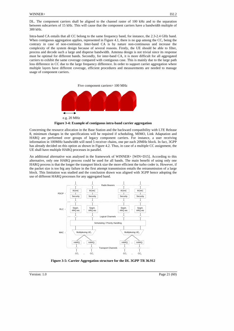
Concerning the resource allocation in the Base Station and the backward compatibility with LTE Release 8, minimum changes in the specifications will be required if scheduling, MIMO, Link Adaptation and HARQ are performed over groups of legacy component carriers. For instance, a user receiving information in 100MHz bandwidth will need 5 receiver chains, one per each 20MHz block. In fact, 3GPP has already decided on this option as shown in Figure 4.2. Thus, in case of a multiple CC assignment, the UE shall have multiple HARQ processes in parallel.
An additional alternative was analysed in the framework of WINNER+ [WIN+D15]. According to this alternative, only one HARQ process could be used for all bands. The main benefit of using only one HARQ process is that the longer the transport block size the more efficient the turbo coder is. However, if the packet size is too big any failure in the first attempt transmission entails the retransmission of a large block. This limitation was studied and the conclusion drawn was aligned with 3GPP hence adopting the use of different HARQ processes for any aggregated band.
Segm.ARQ etc
Multiplexing UE1
Segm.ARQ etc
...
Scheduling / Priority Handling
Logical Channels
Transport Channels
MAC
RLCSegm.
ARQ etcSegm.
ARQ etc
PDCPROHC ROHC ROHC
Radio Bearers
ROHC
Security Security Security Security
...
HARQ HARQ...
Multiplexing UEn
HARQ HARQ...
CC1 CCx... CC1 CCy...
Figure 3-5: Carrier Aggregation structure for the DL 3GPP TR 36.912

WINNER+ D2.2
Version: 1.0 Page 22 (60)
3.2.3 Implications on signalling and architecture
When using carrier aggregation, some signalling information related to the allocation of the resources shall be provided. As previously mentioned, the 3GPP is currently addressing this specific topic where the following two are being considered: the backward compatibility and the reduction of the complexity. However, with the objective of having the maximum system performance, all cases must be studied.
There are five key aspects that WINNER+ has established with respect to signalling in CA:
1. CC discovery and accessibility. Among the configured component carriers, at least one downlink component carrier should transmit the required broadcast information to enable UEs to make an access to the system. In order to increase flexibility and guarantee backward compatibility, WINNER+ proposal is that all CCs were accessible to all UEs, being release 8 or 10. Those UEs with the capability to support multiple CCs will detect the stronger CC in the initial access and receive system information from all component carriers, since this system information will be common among aggregated CCs. However, if any component carrier specific system information exists, this should be transmitted by each CC in a different System Information Block (SIB). It must be noted that, for the sake of simplicity, the synchronization of all of the aggregated carriers is required, with respect to both time and frequency.
2. Once synchronized the UE will use the Random Access Channel (RACH) to get connected to the system. If the CA is symmetric between UL and DL then the DL CC will coincide with its paired UL carrier. However, with the asymmetric carrier aggregation case, in which multiple DL CCs may be associated with only one UL CC, the configuration between UL component carrier and DL component carrier may cause a serious ambiguity problem since the eNB may not know which DL CC is selected by the UE. In order to solve this problem CC must be identified (with a CC-ID) transmitting this information in the corresponding System Information Block (SIB). Besides, this identifier simplifies the scheduling process and allows future handovers between CCs.
3. Another important aspect is related to the downlink signalling control for the scheduling. UEs must be able to decode PDCCH on multiple DL CCs. Any PDCCH on a CC can assign Physical Downlink Shared Channel (PDSCH) or Physical Uplink Shared Channel (PUSCH) resources in one of multiple CCs. Therefore, the CC-ID is needed to specify to the UE on which component carrier the PDCCH assigns PDSCH or PUSCH resources. The eNB could decide on transmitting several times, one per CC, the scheduling information of the whole aggregated band or limit this transmission to just the best CC.
4. Concerning the Physical HARQ Indicator CHannel (PHICH), again in case of asymmetry it will be required to select on which DL CC this channel is transmitted. The WINNER+ proposal is to select only the best CC.
5. In the uplink, in case of a multiple CC assignment, the UE may have multiple HARQ processes in parallel, one per CC. This would mean that multiple ACK/NACKs corresponding to the CL CC transport blocks should be transmitted in using the Physical Uplink Control Channel (PUCCH). Moreover, the UE also will feedback multiple channel quality indicators (PMI/RI/CQIs), one per CC. This is the information used for CC handover and hence it is important to guarantee its proper reception. Again one PUCCH could report about all the UL CC using the CC-ID. The decision on transmitting several parallel PUCCH will lie again on the eNB design.
With regards to the CQI, it has been confirmed in [WIN+D15] that some significant overhead reduction can be achieved if the carrier and scenario are known. Therefore flexibility in the reporting mechanism is recommended. The mentioned CQI reporting procedure can be automatically performed by the UE depending on the frequency carrier that UE is using to communicate with the base station and depending on the speed that characterizes its radio channel. Therefore, in this case no specific requirement on signalling and specific measurement would be expected by the eNB and by the UE in order to perform such a procedure. Nevertheless, assuming that the eNB has the possibility to know the look-up table used by the UE and/or assuming that the eNB has the possibility to set its own look-up table in the UE, the eNB could decide to force the UE to change the granularity of the CQI reporting referring to another pair (number of frequencies, number of TTIs) contained in the look-up table in order to optimize its radio resources allocation strategy. In such scenario, it is expected a new signalling from the UE to the eNB where the UE communicates the look-up table to the base station every time that the UE is going to camp on a new cell or it is expected a new signalling from the eNB to the UE where the eNB communicates its own look-up table every time that a new UE is going to be served. Moreover in this scenario it is expected a new signalling from the eNB to the UE where the eNB communicates the UE to change the level of

WINNER+ D2.2
Version: 1.0 Page 23 (60)
CQI reporting granularity to be used every time that the eNB wants to force the UE to use a new combination (number of frequencies, number of TTIs) of the look-up table.
3.2.4 Research trends in WINNER+
In [WIN+D15] the concept of carrier aggregation has been deeply assessed from different points of view; specifically from physical layer, MAC layer and signalling. There are three proposed techniques:
1. Spectrum aggregation from the physical layer perspective: this research focuses on the viability of using LDPC codes with longer size blocks. As a conclusion of this study, transport block segmentation should be avoided as much as possible, since it naturally entails some degradation in the system performance. The improvement achieved with LDPC is, in most cases, limited to 0.5 dB. Provided that LDPC are not LTE-compatible, its inclusion in WINNER+ seems not justified.
2. Spectrum aggregation from the scheduling perspective: the research focuses on different aggregation strategies and related scheduling approach. A significant advantage of non-contiguous carrier aggregation over contiguous aggregation has been observed, mostly due to the higher spectral diversity of the former strategy. The disadvantage regards hardware redundancy, i.e. the employment of more than one physical (and possibly MAC) layer processing chains. Carrier aggregation is a must in LTE-Advanced and hence a proper allocation of frequencies is recommended in order to make the most of the diversity gain offered by the wider spectrum.
3. CQI signalling in Carrier Aggregation: from the CQI reporting procedure point of view, in a bandwidth aggregation scenario, the research proposes a method to define the CQI report granularity in the time domain and in the frequency domain depending on the carrier the UE is using aiming to save uplink bandwidth without degrading the system performance.
Table 3-2: Characteristics of the most relevant techniques in WINNER+ concerning CA
Technique 1 Technique 2 Technique 3
Duplexing mode FDD FDD or TDD FDD
Link DL or UL DL or UL DL
Topology Flat Flat Flat
Network deployment Independent Independent Independent
Target system LTE-A LTE-A LTE-A
Field of main contribution
Channel coding Scheduling CQI signalling
Gain/Metric 0.5 – 2.5 dB depending on the modulation and BS / SINR difference for equal throughput
25% / System Throughput
X(1.5-3) / Spectral Efficiency
Table 3-2 is summarizing the characteristics and main contribution of the three techniques proposed in WINNER+ concerning carrier aggregation.
3.2.5 Other appealing topics
The use of contiguous spectrum reduces the waste of resources that occurs due to guard bands. On the contrary, non-contiguous carrier components will exhibit additional frequency diversity. Therefore, a deep study must be performed to assess which is the preferred option.
However, the usage of non-contiguous carrier aggregation poses additional difficulties in the frequency planning. Indeed, in this case the coverage of CC will not coincide due to the large path loss differences. One solution could be to increase the power allocated of higher bands or to manage diverse coverage areas using CC HO procedures that should be further investigated. This power control is also needed when the used bandwidth is very wide, although in this last case the power difference is expected to be lower.
Another topic is related to the CC activation. Although LTE- Advanced UEs will support 100 MHz bandwidth BW however UE at any given time may not transmit/receive in the whole spectrum. Indeed, the component carrier activation/deactivation is needed to enable the UE to save battery power. One idea

WINNER+ D2.2
Version: 1.0 Page 24 (60)
could be to adjust the number of component carrier when the UE is moving in an area, most of all, in case of inter-band carrier aggregation with different coverage areas for each CC.
On the other hand, due to hardware limitations in the point of terminal complexity, no more than 8192 FFT (213) will be implemented by vendors [IEEE16mCA]. Considering LTE sub-carrier spacing this results in more than 120MHz whereas for IEEE 802.16m with component carriers of 10MHz this maximum bandwidth is reduced down to 80MHz. All other bands can be received by removing the additional band after receiving the signal of full bandwidth, although this method has problems of loss of SINR for large bandwidth. Another approach is to use multiple RF transceivers. In this case, though the guard bands of each component carrier cannot be utilized, the above-mentioned loss is minimized. Moreover, it requires additional complexity but the combination of over-sampling for FFT and rate-conversion filter can be also considered.
Another issue is the existence of such a large continuous bandwidth. The result of WRC 2007 may not allow such wide carrier bandwidth for new radio systems. Given the current spectrum distribution, the only valid alternative to process the entire frequency band from about 400 MHz to about 6 GHz seems to be the use of parallel receivers for each different band [WIN+D32].
This may lead to another hardware limitation, due to antennas, at least on the mobile side. Indeed, the antenna should cover the whole set of bands decided by WRC07, especially the lower band (698-960 MHz) (not to mention 400 MHz). If we assume its size should remain compatible with that of a smartphone, then its electrical dimension (dimension over wavelength) in the 698-960 MHz band will be about 0.25, and its relative bandwidth (bandwidth over central frequency) should be about 0.3. For these values, electromagnetic theory predicts a maximum possible radiation efficiency (ratio of power actually radiated to the power put into the antenna terminals) of about 0.25, which is quite poor. Indeed, radiation efficiency decreases as the antenna length decreases and for larger relative bandwidths. Therefore, alternative solutions should be found, such as frequency reconfigurable antennas. Still, it may remain difficult to guarantee a large enough bandwidth at the lowest part of the band (698 MHz). Moreover, LTE standard imposes two antennas at the mobile side. These two antennas should not be coupled, in order to avoid power loss. In addition, for MIMO algorithms to be efficient, these antennas should be decorrelated. The design of such antennas is an open topic ([WIN+D51]).
The last hardware limitation is the difficulty for the RF part when aggregation is performed on non contiguous bands. As explained in [SWB06] there is a research challenge related to the mitigation of intermodulation distortion, especially if fragments share a transmit/receive chain, or chains need combining to share an antenna or amplifier, to reduce component count and overall size.
3.3 Femtocells
3.3.1 Introduction
Femto-cells are low-cost, low-power, short-range, plug-and-play base stations, which can be used for offloading traffic from the macro cells. This is of particular interest since significant portion of the traffic is originated from indoor usage, the data rates are growing and penetration loss limits the indoor-to-outdoor coverage.
Femto-cells offer several benefits to both consumers and operators. For consumers, they provide improved mobile coverage and QoS in small-office, home-office (SOHO) environments, and high performance mobile data providing faster access to mobile services and mobile content. For operators, Femto-cells offer an effective way of increasing coverage and capacity at home.
An example of a network with 19 cells and on average three femtocells (circles) per macro cell area is shown in Figure 3-6. UE’s are marked as black dots. In this example there is a group of UEs which are able to connect to a femtocell; the rest of the UEs can use only the macro network. This is the most plausible scenario – the femtocell owners do not want outsiders to access their femtocell.
Figure 3-7 illustrates the interference problem associated with femtocells. Femto base station’s (HeNB in 3GPP terminology) downlink transmission causes interference to the macro UE (MUE) downlink reception. On the other hand, also macro network’s DL transmission interfereres with the FUE downlink. Also a third type of interference exists (not visible in the figure) where two closeby femtocells interfere.

WINNER+ D2.2
0 500 1000 15000
200
400
600
800
1000
1200
1400
Figure 3-6. Example of randomly deployed femtocells (red circles)
eNB
HeNB
MUE
FUE
InterferenceUsefull signal
HeNB
FUE
Figure 3-7. The interference problem with femtocells.
Despite the promise of femtocells, many concerns still remain, especially cross-tier interference. Two particular aspects of femtocells give rise to serious interference issues, such as the co-channel spectrum sharing between femtocells and macrocells and the “random” placement of HeNBs. Instead of allocating dedicated channels to HeNBs, sharing spectrum is preferred from an operator perspective yielding higher spectral efficiency. However, since HeNBs are installed by end-users in a “plug-and-play” fashion, interference in two-tier networks is quite different from conventional cellular networks, and hence endangers their successful co-existence. On the other hand, due to the non-existent coordination between HeNBs and macrocell BSs, centralized cooperation to mitigate cross-tier interference is unfeasible, which calls for decentralized strategies for interference management.
Version: 1.0 Page 25 (60)

WINNER+ D2.2
Version: 1.0 Page 26 (60)
3.3.2 Femtocells in 3GPP
In 3GPP, femtocells are contemplated in TR [3GPP25820]. The goal of this study was to characterize 3G Home NodeB environment, to outline obstacles, define higher level requirements, and offer recommendations for the specifications. This TR concentrates on layers 2 and 3; it is assumed that layer 1 is mostly unaffected .
Concerning LTE-A, following aspects are being considered:
In 3GPP the HeNB connects to the mobile network through the femto-GW, which serves a large number of HeNBs via the Iuh interface, going through the security gateway (SeGW). Connection from the femto-GW to the core network (CN) is done with the existing IuCS/IuPS interfaces. No changes to the existing CN are needed.
Security is an important aspect with femtocells. In the 3GPP femtocell architecture security consists of two parts: HeNB authentication (using X.509 certificates that are configured in HeNB and femto-GW; furthermore, HeNB may have UICC, similar to a SIM card in mobile devices) and ciphering across the broadband connection between the HeNB and femto gateway. Security specifications were be completed in Release 9.
QoS requires special attention due to the nature of the backhaul connection. Specifically, the link from the femto to the mobile network is the primary focus due to asymmetrical nature of broadband technologies; also the broadband link is usually shared with both femto and non-femto traffic.
Access Control: Mobile users can connect to femtocells under two different access control policies. In the closed access femtocells, the concept of Closed Subscriber Group (CSG) is introduced to restrict the access to pre-defined members. The open access mode has been defined to allow any mobile user to connect to a femtocell. The combination of open and closed access mode is called hybrid mode and been added to 3GPP Release 9 to allow for flexible femtocell deployments.
Mobility management is paramount for the possible integration of femtocells into the operator’s core network aiming for a seamless connectivity between macro and femtocells. In 3GPP standardization of Rel-8/9, femtocell mobility management for idle and connected mode was studied. During Rel- 8 standardization, idle mode and outbound connected mobility mode have been standardized whereas inbound connected mobility mode has not been finalized. For Rel-9 the problems related to inbound connected mode mobility like PCI confusion, CGI reading/proximity indication and access control have been solved for indoor fixed femtocells, allowing for an optimized macro to femtocells handover with uninterrupted service in all modes. Another aspect of mobility management is paging, where the large number of femtocells leads to high paging traffic due to the tracking area reuse between macro and femtocells.
3.3.3 Uncoordinated femtocells
The common denominator in the uncoordinated femtocells is that there is no coordination between macro and femto networks. However coordination between femtocells is allowed; therefore no changes needed in macro network. The method of uncoordinated femtocells is divided into two techniques: self organization (for femto-to-macro interference avoidance) and beacon based approach (resource allocation optimization between adjacent femtocells.)
In the proposed self organized scenario [WIN+D12, WIN+D16, WIN+19] there is no X2 connection between macro- and Femto-cells, or any other means to control interference. Instead, we use self organization (cognitive radio) in the Femto-cell to avoid femto-to-macro interference. Femto users measure the path loss from the DL of macro base stations to FUE’s. Results are combined at the HeNB to create an estimate of the Femto-to-Macro interference. Femto cells use the uplink band of the macro cell in a TDD mode. If the estimated Femto-to-Macro interference is small (path losses are large), Femto-cell operation is allowed with small transmission power. Since the UL of the macro cell is used, the macro cells do not experience interference from the Femto-cells.
In the beacon based approach femto base stations broadcast control information to monitor the spectrum usage situation locally [WIN+D12]. The UE’s receive beacons from several HeNBs and when combined with information about the UE’s physical location, local awareness of the spectrum usage situation can be formed. This information is then sent back to the HeNB. Combining these messages gives the HeNB information about the spectrum usage situation in the entire cell area [WIN+D12].

WINNER+ D2.2
Version: 1.0 Page 27 (60)
The broadcast messages include information about neighbor cells, which resources the neighbors are using and how much interference the neighbors are causing. Optionally, information about bandwidth demand estimates and TDD UL/DL switching point is also broadcast.
Each HeNB should estimate if the resources currently used by it are sufficient for the operation or not. If an HeNB has more resources than it needs, the HeNB should release some resources, and modify its own beacon information accordingly (i.e. announce that resources released are now free for other access points.)
In the synthesis of these two methods, we select the self organization as the baseline technique. It is used for femto-to-macro interference avoidance; this requires that the femtocells operate on the uplink band in TDD mode. The problem with this method is that adjacent femtocells cause interference to each other. This is solved by the beacon based approach: local awareness of the spectrum usage is used as a side information in the PRB assignment algorithm for femto-to-femto interference avoidance.
3.3.4 Coordinated femtocells
There are two techniques which require coordination between femtocells and the macro network: (1) ICIC between femto and macro; (2) game theory.
The first innovation introduces an interference coordination technique for femtocells. The most critical scenario from the interference point of view is a macro UE located in the vicinity of a femto cell. Despite the low transmission power in the femtocell, there may be detrimental interference between macro UE and HeNB.
The cell area is divided into regions [WIN+D12, WIN+D16]. Each cell-edge region is characterized by the corresponding neighboring eNB (the one which is closest to the area). Each HeNB uses RSRP (Reference Signal Received Power) measurements from FUEs to establish whether it lies in one of the cell-edge areas or not. If not, it is then classified into belonging to a cell-interior area (near the serving eNB). High interference indicator (HII) messages (specific to each region) are sent to all femtocells located in the region. The procedure is similar to the UL intercell interference coordination (ICIC) [TS36420, TS36423], and extended to DL.
When the macro UE (MUE) detects potential interference from a femtocell, it signals the femto ID to the eNB, which then uses the HII message to inform the femtocell about which physical resource block (PRB) it may schedule or not. The femtocell then decides how to assign resources to their FUEs, thus preventing them to use the same DL and UL physical resources. As a result, FUEs and MUEs that re-use the same resource blocks are inherently spatially separated.
The second coordinated method uses game theory (GT) [WIN+D19], which can be used to model the scenario where eNB and HeNB share the same spectrum. It is shown that there is an optimal number of HeNB that can be deployed in a network, after which the overall efficiency of a network decreases. Moreover, through the concept of hierarchy in which the eNB is cast as the leader while the HeNBs are cast as the followers in the game, it is shown that the performance of the total sum-rate network can be improved as compared to the purely non-cooperative approach. Moreover, the decentralized hierarchical approach is shown to bridge between the both the non-cooperative and fully centralized approach.
To combine these techniques, we use the ICIC as the baseline method. It is used to avoid femto-to-macro interference in DL. This method is used to deny femtocells from using PRB’s which would cause unacceptable interference. For those PRB’s which would cause smaller amount of interference, game theoretical approach is used to optimize power levels and PRB assignment.
3.3.5 Requirements on architecture, signalling and measurements
Signalling is required by all techniques. In the case of self organized femtocells, the FUE’s have to measure the RSRP from the macro BS and estimate the path loss, and send the estimate to the HeNB. Also some changes due to TDD on the UL band in the signaling and frame structure are needed.
When beacons are used to combat interference, the beacons structure needs to be defined (existing broadcast channel can be utilized), as well as UE feedback signaling.
In the case of coordinated femtocells, the ICIC signaling between femtocells and macro network is needed; for the game theory same signaling channel can be used to exchange channel information.

WINNER+ D2.2
Version: 1.0 Page 28 (60)
3.3.6 Conclusions and Future Research
Femtocells are a promising method to increase system capacity of a cellular network. Due to their uncoordinated nature, minimal changes are needed in the macro network. On the other hand, if some amount of coordination is allowed, the performance can be improved by more advanced interference control and channel allocation methods. This would affect both macro- and femtocells; decreased femto-to-macro interference would increase macro cell throughput, and more optimal channel allocation in the femtocell would improve its performance.
In this subsection we have revised the femtocell innovations in WINNER+. They can be divided into two categories: coordinated and uncoordinated.
In the coordinated approach, the interference from the macro network to the femtocell is avoided by extending the ICIC mechanism to the femtocells. Game theoretical approach is then used to further optimize the resource usage. Note that even though this method is called “coordinated”, the nature of the femtocells is still uncoordinated; their deployment is done by the end user, in a plug-and-play fashion, and the network has no control over the femto BS locations.
In the uncoordinated case, there is no signalling between macro and femto networks. Instead, femto-to-macro interference is avoided by using TDD on UL band in the femtocell. In this way, when the distance to the nearest MBS is large enough, the femtocell does not cause any interference. The distance is estimated by measuring the path loss from the MBS. Beacon based approach is then used to optimize resource usage between adjacent femtocells.
Summary of femtocell concepts, their applicability to FDD/TDD and UL/DL, expected performance and compatibility is gathered in Table 3-3
Table 3-3. Summary of femtocell concepts.
Coordination Technique Applicability to FDD/TDD;
UL/DL
Expected performance Compatibility to LTE(-A)
Coordinated femtocells with ICIC
FDD and TDD, DL
20 dB decrease in interference power [WIN+D12, WIN+D16]
MUE’s need to detect femto interference + send HII to eNB. Support for ICIC for the femtolayer required in eNB and HeNB.
Coordinated
Femtocells and game theory
FDD and TDD, DL
Increased sum-rate [WIN+D19]
MUE’s need to detect femto interference + send measurement reports to eNB. There is a need for an eNB-HeNB interface.
Self organized femtocells
All (femtocells always in TDD)
170 % increase in cell median TP with open access [WIN+D19]
No changes required in the macro network. TDD on UL band for the HeBN and FUE and measurements needed.
Uncoordinated
Femtocells with beacons
All 200 % increase in median throughput [WIN+D12]
Broadcast beacons need specifications; as well as measurements and signaling on the UE side.
Femtocells are not a mature technology. There are still issues regarding interference; especially femto-to-femto interference – even if it can be partially solved by the beacons – still limits the performance. The solutions to the problem have to be decentralized, and this is the major challenge.

WINNER+ D2.2
Version: 1.0 Page 29 (60)
Another important problem to be solved is mobility management. This includes handovers to and from femtocells. While this has not been studied in WINNER+, in practical networks the problem has to be solved.
3.4 Relaying
3.4.1 State-of-the-art
Initially designed for coverage extension mainly, relays used to be very simple devices where the signal is amplified and forwarded immediately. In these devices no processing in the base band occurred and their price was significantly lower compared to real base stations to offer significant advantages. The backhaul could be implemented with microwave links in ad-hoc frequency bands to avoid interferences with the access link, or in-band with appropriate (receive and transmit) antenna isolation avoiding Larsen-like effects. As such, these devices didn't need a specific requirement in the standard, and could be deployed on top of almost any network via proprietary solutions. However this flexible approach revealed quickly significant drawbacks after the first deployments. When one or several of these devices failed, there was no way to notice it but checking on site that every thing was up and running. Because it was deployed in areas without connexion to the network, there was no monitoring possibilities devices and therefore and increased operational cost. Operators were therefore reluctant to deploy relay-based solutions, and used them on a case-by-case basis when no alternative is envisaged.
In the scientific literature, relays have been introduced through the relay-channel notion by E. C. Van der Meulen [Meu71] in 1971. As opposed to the two-way channel initially introduced by Shannon where two entities communicate with each other in two opposite directions, the three-terminals communication channel proposed by Van der Meulen models a situation where communication occurs in a specific direction only from a source to a destination, through a third collaborative entity, called the relay. The objective is to design a communication scheme optimized from the spectral efficiency point of view. This specific channel is one of several listed in [Meu77] by the same author. The author provides the first upper and lower bound for such a channel, which are later completed by Cover and El Gamal capacity theorems for the relay channel [CG79]. In their article, Cover and El Gamal determined the channel capacity for a certain class of channel they call physically degraded using three structurally different coding schemes: facilitation where the relay does not actively help the source but tries to minimize its interferences with the sources, cooperation where the relay fully decodes the source and retransmits, jointly with the source, and observation where only a part of the source is retransmitted using source coding with side information. The name of this latter scheme has been introduced by Laneman, Tse and Wornell in [LTW04] where they also first introduced the well known protocol definitions: Amplify-and-Forward and Decode-and-Forward. In this article though, half-duplex terminals (the relay cannot transmit and receive simultaneously) are considered with channel state information at the receiver only, most probably for simplicity reasons.
More recently in an effort to bring relays in real deployments, significant research work has been carried out in the EU FP6 project WINNER II on channel models and simulation as well as baseline work for the current 3GPP activities [WIN2D6137][WIN2D351][WIN2D352][WIN2D353][WIND61314]. In the initial 3GPP work for LTE-A, relaying was defined as a study item, and the merits of two-hop decode and forward relays with limited scope are under study in [3GPP36814]. Further relevant examples on recent relay research analyzing the aspects of capacity enhancements and coverage extension can be found in [SW07][SL05][SHW08][LRR09][BRR09]. In these studies, relays are rather envisaged to boost capacity locally, rather than for coverage extensions in order to improve the throughput distribution uniformity in the network. Other promising research fields are multi-hop transmissions in a hope to better spread the transmit power in the network, or moving platforms (e.g. in trains or buses) where a large number of customers can work conveniently on their laptops in quasi stationary conditions.
3.4.2 Objective
As mentioned above, relays were initially thought as coverage extension devices mainly. With the data traffic increase operators are facing in their networks, a solution to improve the bitrates in specific area is the densification of the transmitted power per surface unit. However increasing the number of base stations is costly and operators have probably reached a density limit which is difficult to overcome. People do not welcome the idea of having antennas installed on rooftops. In addition, densification is a very expensive operation mainly due to the site acquisition. Relays can be mounted outdoor, on e.g. walls and lamp posts, thus cutting the site cost. This situation prompted the study of relays, viewed as capacity improvement devices, at a reduced cost. This in turn laid the ground for the study of relays in the WINNER+ project, trying to solve the issues raised by the following constraints:
- A penalty in terms of throughput due to the multiplexing of the access and backhaul link traditionally used in a relay in-band configuration.

WINNER+ D2.2
Version: 1.0 Page 30 (60)
- A device significantly cheaper than a base station which translates first into a size and transmit power constraint.
- A device targeting either coverage extension or capacity enhancement.
Whether the backhaul link of relays would be in-band or out-of-band was a first question. Out-of-band relays are not considered in 3GPP, and are anyway less complex than in-band relays. Thus all solutions envisaged in the project considered in-band relaying. This was also the studied case in the 3GPP even though the two cases were foreseen.
3.4.2.1 On the cost constraint
Designing cheap devices is a complicated task because vendors and operators do not share easily their knowledge on the topic. Vendors have a very good insight of the cost of the device itself (CAPEXs) and operators now the operating costs (OPEXs). In the WINNER+ project, the cost aspect of the device has only been addressed through the AF versus DF differentiation of relays. Amplify and Forward (AF) relays were supposed to be cheap devices because of their simplified function: amplification. Base-band processing or recording of any signal is not possible in that case which allows a relatively cheap device to be designed. On the other hand, Decode and Forward (DF) relays are more complicated devices since they assure all functionalities up to the third layer of the open systems interconnection (OSI) model and therefore have base-band processing capabilities as well as memory storage capacities. High level parameters like the size of the relays or even their density (be it measured per surface unit or per base station or even per terminal) have been less considered in the project. Some innovation like the Multiple User Multiple Relay (MUMR) network [WIN+D19 section 6.2.1.2] described below completely abstracted this constraint and proposed quite dense topologies (a high number of relay compared to the number of terminals).
3.4.2.2 On the multiplexing penalty
This is the major issue of relays. To avoid interferences between the transmitter and the receiver, relays have to listen before they retransmit, which may induce up to 50% loss of resources for terminal accessing the network through this means. In the Winner+ project, several attempts have been made to overcome this limitation.
- A technique called two-way relaying [WIN+D19 section 5.2.3] where terminals of the same relay-cell communicate each other via the same relay. Although the scenario is debatable (some argue that in meeting rooms for instance, peer to peer communications though potentially quite useful, are never used while being available via WIFI), it addresses clearly the multiplexing penalty of relaying in an innovative way.
- A careful choice of activating the relay or not, ensuring that the quality improvement obtained by the relaying scheme will be such that the resulting more efficient use of resource blocks will more than compensate the throughput penalty.
- Finally, the up to 3dB penalty of accessing the network via a half duplex relay can be handled via the scheduling [WIN+D19 section 5.2.1.1]. Adding more fairness in the scheduler for such users can be done at the price of a degraded average overall capacity. It is not straightforward though and requires a modification of the signalling in place in LTE-R8 standard.
3.4.2.3 On the capacity or coverage improvement
A scheduling algorithm, designed to take care of urgency as well as ensuring some fairness to users has been extended to the relaying case.. The basic idea was to bring urgency on top of relaying, which means giving the priority to urgent users and then to relayed users. The performances were assessed through system level simulation considering an urban macro deployment and non full buffer traffics (here VoIP). The relaying concept inside the scheduler improves performance of the system, in terms of residual FER, and UE throughput. The scheduling algorithm can be tuned in order to favour users either based on urgency only, or on channel quality only, or on a combination of both. In this latter case, simulation results show that it outperforms all other cases in terms of throughput and FER. Further studies will consider more complex scenarios including heterogeneous traffics (e.g. VoIP and HTTP) in order to study in more depth the benefits of the proposal. A distributed (over the base station and the relay) LDPC code [WIN+D19 section 5.2.2.4] was proposed. This scheme assumes a cooperative reception between direct and relayed links. Some new parity bits are built by the DF relay, resulting in a large improvement over the simple repetition code, where the initial parity bits are repeated. However the proposal lacked of system level results, and is not compliant with existing turbo-code based coding scheme in the 3GPP standards.

WINNER+ D2.2
Version: 1.0 Page 31 (60)
Finally a study of relaying in the framework of CoMP has been conducted. This study analysed the user throughput in the urban wide area and Manhattan grid deployment scenario and paid particular attention to the cell-edge and median user throughput. In the case of the urban wide area scenario, the study showed that while the downlink performance is not improved by relaying compared to cooperative multi-point transmission, the uplink throughput can be significantly increased using relay nodes. Additionally, a cost-benefit-tradeoff analysis revealed that it is cost-efficient to deploy relay nodes in the uplink but not in the downlink. This conclusion slightly changes for the Manhattan grid deployment scenario, where indoor relay nodes are able to improve the performance by multiple decades compared to cooperative multi-point transmission as well as if relays are deployed only outdoors.
3.4.3 Conclusion
The work carried out on relays within the project has not allowed drawing a clear conclusion on the coverage and capacity improvements relays can bring in specific area of the network yet. However, it did help understanding the problems and concentrate on most important issues. Since it was decided from the beginning of the project to focus mainly on LTE-Release 8 backward compatible innovations, the research fields were limited. Maybe the next steps would be multi-hop (more than two) communications, moving relays (in train or buses) or even user terminal acting as relays because from the topology point of view, we still have many things to improve: the way energy of signals is spent if assuming multi-hop communications can be largely improved.
The most promising relaying techniques are presented in Table 3-4.
Table 3-4: Summary of selected relaying techniques.
Applicable to FDD/TDD
Applicable to UL/DL
Expected performance
(+ source)
HYGIENE scheduling with relays
FDD, DL HYGIENE without relays performs better than classical schedulers for mixed traffic [WIN+D15]
Integrating CoMP and relaying
TDD,FDD, DL Worst-user throughput performance improved by about three orders. With four relays [WIN+D18] -
Distributed Space-time coding
TDD,FDD,DL Exhibits a 120% gain on the link capacity [WIN+D14]
Distributed LDPC coding TDD,FDD, DL Split-extend scheme provides up to 4dB gain w.r.t. repetition coding schemes
[WIN+D18]
Two-way relaying TDD [WIN+D17]
3.5 Network Coding and Peer-2- Peer
Network coding [ACL+00] is a new and promising strategy for information transmission in networks. It allows messages from different sources (or to different sinks) to mix in the intermediate nodes hence yielding performance gains in terms of e.g., network flow, robustness or energy efficiency [X+08]. Though network coding (NC) was originally proposed for error-free computer networks, the principles of network coding can be applied also to implement wireless communications.
Most methods for network coding in wireless communication [CKL06, LJS06] use binary network coding: exclusive or (XOR) due to its simplicity, which may not be optimal. For wireless cooperative networks, designed non-binary network codes can have significant performance improvement compared to binary ones. The first innovation describes the usage of non binary network coding in cooperative and multiple-relay scenarios. The second innovation tackles the relay selection and user grouping in a relay multiple access network coding scenario.
Peer-to-peer radio communications, also referred to as Device-to-Device (D2D) communications, is expected to become a key feature to be supported by next generation wireless systems. Usage of D2D

WINNER+ D2.2
communications will bring benefits to many areas of operation of cellular networks. For example, it will offload the cellular system, it can lead to reduced battery consumption, increased bit-rate and robustness to infrastructure failures.
3.5.1 Network Coding & Peer-2- Peer in LTE-A and beyond
Network coding and P2P communication have not been discussed on 3GPP. As today, both techniques would not be part of release 10 which is expected to be finalized later this year.
3.5.2 Non Binary Network Coding in uplink relaying scenario: Network coding for multiple-user multiple-relay systems
The method consists of using non-binary network codes on top of channel codes to rebuild source information from the minimum possible set of coded blocks. In this sense, the network codes achieve the min-cut capacity for mobile or fixed relaying networks, which have the dynamic topology due to block erasures in channels. Further the used linear non binary network codes are asymptotically optimal in terms of diversity (diversity order 3) as shown in [XS09].
Figure 3-8: Two-user two-relay networks with network coding.
The multiple-user multiple-relay (MUMR) wireless networks consists of M ( 2M ) users have independent information to be transmitted to a common base station (BS), with the help of ( ) relays. An illustration for MUMR network comprising of a two-user, two-relay is shown in
N 2N
1 2I
21 I 21 2II
Figure 3-8. MUMR uses a linearly independent (LI) network codes, over certain finite fields, on top of the channel codes. The addition “+” operations are conducted in the finite Galois field GF(4). Thus, it will not cause any bandwidth expansion or extra power consumption. The relaying and local messages are encoded by network codes in the relay. The network codes are designed such that any two successfully received blocks out of four transmission blocks can rebuild two source message blocks. In the first time slot, the
two source nodes use proper channel coding to transmit their own messages I and respectively (in
e.g., different frequency-orthogonal channels). In the second time slot, if both relay nodes successfully decode the channel codes, the transmitted messages for user 1 and user 2 are encoded using network
coding as I and , respectively. Then, the resulting blocks are channel encoded and
transmitted. Here successful decoding means that information is received error-free. It follows that the BS receives four codeword transmissions with four different message combinations: I1, I2, I1+I2 and I1+2I2, constituting a resulting nonbinary LI network code.
3.5.3 Network Coding for uplink relay-based wireless communication system
It was shown that when introducing of network coding in a multi-cell wireless relaying system, an adequate joint or disjoint user grouping and relay selection are required in order to exploit fully the system performance. In [MOS08, MOS09] it was proposed the usage of user grouping and relay selection whenever NC is performed in order to reach the capacity gains expected from the decrease in the number of transmissions.
In a wireless network system there is a set of active users in a cell at a certain time instant from which two (or more) users shall be selected for network coding operation. Obviously a random selection will not yield the optimal system capacity. In fact if we choose to pair users randomly then we could end up pairing users with non-complementary channel conditions to the relay and base station, and consequently losing the advantage provided by network coding. The proposed user grouping scheme allows only one of the network coded pair to increase its SINR through the relay connection whereas the other user has to be
Version: 1.0 Page 32 (60)

WINNER+ D2.2
Version: 1.0 Page 33 (60)
decoded through its direct connection's SINR. Based on the quality of the links of these users, to the relay and/or to the base station, the user grouping is carried out in order to optimize a certain cost function which can be in terms of sum-capacity, outage, interference or any other performance measure of interest. The cost function can be periodically derived at the BS.
When network coding is introduced, the relay selection scheme should be aware of this operation and select the best relay accordingly. Otherwise, if the relay selection choice is simply based on an individual user without any consideration to the other user in the pair, this other user could be detrimentally affected. Consequently, the relay selection algorithm should be aware of the NC operation and take into account both of the sources to be network coded when selecting the relay node. We specifically considered the distinct cases where network coding is performed on the relay that maximizes: 1) the capacity of the weaker source, or 2) the capacity of the stronger source, or 3) the sum-capacity of the network coded pair. The scheme [MOS09] selects one relay out of a set of relay nodes on which network coding of a pair of users can be performed. As multiple users are typically active at a certain time, an optimal performance (corresponding to a system throughput gain of 75%) willbe reached when the relay selection algorithm is performed jointly with user grouping.
3.5.4 Peer to Peer Communications
Device to device (D2D) communication as an underlay to the cellular network operation was proposed in [WIN+D13]. The BS is in control of the resources that are used by UE1 and UE2 for D2D communication. Further, the BS can set the maximum transmit power of the D2D transmitters to limit the interference to the cellular network.
The D2D concept was first investigated as an enabler for supporting new local special services like a media server during a rock concert without need for an additional air interface in the UEs and with interference control in the cellular network. Then, the D2D concept was investigated as a means to maximize the overall throughput in the cell. An LTE network in TDD operation was assumed. The throughput was evaluated in an isolated cell scenario under different resource allocation strategies between the D2D and the cellular network users. The study shows that without constraints an up to 7-fold increase in cell throughput can be achieved. The gains are lower when offering a guaranteed rate to the cellular users. Nevertheless the cell throughput can still be doubled or even increased 3 times depending on the D2D link distance.
3.5.5 Performance
The performance gains as well the ideal usage scenario for the network coding and Peer-2-Peer techniques are listed in Table 3-5.
Table 3-5 The Network Coding & Peer-2-Peer Selected Techniques
Gain Scenario Comment
Network coding for multiple-user multiple-relay
4dB SNR gain at 10-3 FER
FDD, Uplink FDD and TDD, UL
User Grouping for uplink relay NC
Up to 35% capacity gain
FDD and TDD, Uplink FDD and TDD, UL
Relay Selection for uplink relay NC
Up to 30% capacity gain
FDD and TDD, Uplink FDD and TDD, UL & DL
Peer to Peer Up to 7-fold in the cell throughput
Underlay LTE TDD
3.6 Multi-user MIMO Systems and CSI Acquisition
3.6.1 Introduction
The innovations introduced in WINNER+ project [WIN+D19] focus mostly on seeking for system performance improvements from advances in the acquisition of channel state information at transmitter (CSIT) – short term or long-term – via new signaling and estimation solutions. The framework of cellular multiuser MIMO systems is considered, where a base station employing an antenna array communicates with multiple user terminals, each equipped with one or more antenna elements. The framework of the presented solutions consists of spatial user multiplexing or scheduling, and beamforming by means of

WINNER+ D2.2
Version: 1.0 Page 34 (60)
linear transmit precoding. The problem of acquiring the CSIT consists of multiple tasks, such as pilot signal design, channel state and quality estimation, as well as feedback signal design. All these aspects are addressed in order to enhance the system performance. The innovations can be grouped into four main categories presented in Table 3-6. Each subgroup includes a multitude of proposals of which a more detailed description can be found in [WIN+D19]. The performance gains in general, and the backward compatibility with LTE of the proposed innovations are summarized in Table 3-5.
Table 3-6: Summary of WINNER+ AAS innovations [WIN+D19].
Applicable to FDD/TDD
Applicable to UL/DL
Expected performance
(+ source)
Compatibility to LTE and LTE-A /
Topic for future studies
Enhancements for codebook based multi-antenna transmission
FDD (and TDD)
downlink
Improved spectral efficiency for cell-edge
users
(D1.4, D1.7, D1.9 Appendix E)
Not directly compatible to LTE: feedback signaling changes
needed /
Can be considered for LTE-A
Feedback methods for multi-user MIMO zero-forcing
FDD (and TDD)
downlink
Improved spectral efficiency in
environments with high antenna correlation
(D1.4, D1.7, D1.9)
Not compatible to LTE /
Can be considered for LTE-A (DL precoded demodulation
pilot used)
Resource allocation schemes for TDD systems
TDD downlink and uplink
Highly increased overall performance if accurate
CSI available
(D1.4, D1.7, D1.9 Appendix E)
Not directly compatible to LTE: multiantenna UL sounding pilot
needed /
Can be considered for LTE-A (pilot signaling expected to be
compatible)
Coding and decoding Any duplexing mode and link
Provides diversity, coding, and decoding gain for point-to-point
links
Mostly readily applicable to LTE
Space-time network coding for further studies
3.6.2 MU-MIMO Support in IMT-A Proposals
Studies and standardization efforts are on-going to construct two IMT-A compliant systems, 3GPP LTE-Advanced (LTE-A) [3GPP36814][Nak09] and WiMAX evolution IEEE 802.16m [IEEE16mSDD]. In terms of MIMO transmission, both standards are evolving in the same direction: Up to eight transmit antennas (2, 4 or 8) at the BS and up to four transmit antennas (1, 2 or 4) at the MS are supported. While simple Tx diversity modes are still supported, the emphasis has moved to spatial multiplexing and beamforming. Both open-loop and closed-loop SU-MIMO and MU-MIMO modes with adaptive rank are supported. In order to facilitate reception, dedicated demodulation pilots – reference symbols known to the receiver are precoded in the same way as data – are provided. On the other hand, for the support of transmit precoder matrix selection, common pilots, i.e. sounding signals or reference signals that are transmitted that are not spatially precoded are used for CSI estimation. The reference signal arrangement is different from that in LTE Rel. 8, and in principle it facilitates any non-codebook based spatial precoding method, provided that CSI feedback is sufficient.
In order to facilitate more general precoding, LTE-A is considering explicit CSI feedback methods, i.e. the reporting of the MIMO channel matrix, in addition to the conventional PMI (precoding matrix index) feedback. The uplink sounding reference signal is non-precoded and antenna specific and the acquired CSI via sounding can be used for generic downlink MU-MIMO precoder design. As an enhancement to LTE uplink, LTE-A will support also uplink MIMO transmission via codebook based linear precoding,

WINNER+ D2.2
Version: 1.0 Page 35 (60)
allowing up to four spatial streams per MS. Uplink MU-MIMO with maximum single stream per user was already available in LTE.
In the downlink SU-MIMO mode, IEEE 802.16m plans to allow the maximum of eight spatial streams per MS. In the MU-MIMO mode, maximum of four simultaneous streams – one per MS – are allowed, even when the BS has eight transmit antennas. On the other hand, the uplink MU-MIMO mode allows multiple spatial streams per user.
For the downlink closed-loop codebook based precoding, IEEE 802.16m does not explicitly define the precoding matrices, but allows them to be vendor-specific. The codebook may be optimized for correlated channels, and advanced options for PMI feedback are suggested: PMI may be transformed with long-term CSI, or PMI may provide differential knowledge of the short-term CSI. The long-term CSI, including the transmitter spatial correlation matrix, may be reported by the MS separately as well. In TDD systems, uplink sounding based precoding is supported. Advanced uplink sounding methods are proposed: the unquantized spatial DL covariance matrix or its eigenvectors may be conveyed to the BS via the sounding channel.
Furthermore in IEEE 802.16m, in the case of uplink closed-loop codebook based precoding, the BS signals the PMI to be used in the uplink transmission. The codebook may be created by the BS, or by the MS as instructed by the BS. In TDD mode, adaptive precoding based on measurements of the downlink reference signal is allowed. In this case, the form of the uplink precoding matrix need not be known by the BS.
Backward compatibility will be provided so that LTE-A can support legacy LTE devices. Likewise, 802.16m will support legacy WiMAX devices. In 802.16m the support can be created by different time zones so that some of the subframes comply to the old standard.
The descriptions of both systems, 802.16m and especially LTE-A, are still missing a lot of details, and the currently specified features may well change before the standards are ready. However, it seems that support for a relatively broad range of advanced linear MU-MIMO schemes will be available.
3.6.3 Selected Advanced Antenna Schemes and Applicable Scenarios
The WINNER+ multi-antenna concept supports multiple scenarios with different spatial/temporal channel characteristics. Users with low velocity may benefit from closed-loop transmission with different feedback rates, while high velocity users must rely on open-loop transmission based on, e.g., per antenna rate control or space-time-frequency coding. For a given deployment scenario, an appropriate spatial scheme must be chosen. As the user is moving in the network, the transmission must be adapted continuously to the spatial properties of the channel and the interference.
Different multi-antenna transmission methods are supported, including single-user (SU) MIMO, MU-MIMO, single-stream beamforming, transmit diversity. Moreover, efficient user grouping and resource assignment based on users’ spatial properties and transmit strategies are supported.
Different levels of feedback in both up- and downlinks are required for different multi-antenna transmission schemes, including codebook feedback, channel quantisation, uplink measurements relying on channel reciprocity, and channel rank or correlation information. In addition, link adaptation and resource allocation information transmitted on the forward link must be provided to the terminals, such as. modulation and coding schemes per resource block and user grouping/allocation information. More detailed description of the generic WINNER+ TX structure is provided in [WIN+D21].
In the WINNER+ project, most of the contributions consider relatively low velocity terminals allowing for the utilisation of CSI at the transmitter. In the following, the preferred multi-antenna transmission methods both in rural/wide area and urban/local area scenarios with relatively low velocity are provided.
3.6.3.1 Rural and Wide Area Scenarios with Low Angular Spread,
Users located in environments with low angular spread, including rural and wide area scenarios can be served by adaptive beamforming or code-book-based precoding, relying mostly on statistical CSI and simple CQI feedback. In conventional single-cell solutions, terminals estimate their channels based on common downlink pilots, and directly feedback their preferred precoder choices to the base station. In the proposed extensions, both potential intra-cell and inter-cell interference are considered for the precoder selection instead of relying only on the terminal specific feedback. The improvement arises from interference management solutions that enable either interference rejection receiver processing in terminals, or interference avoidance scheduling in the network side.

WINNER+ D2.2
Version: 1.0 Page 36 (60)
Codebook based multi-antenna transmission
One of the adaptive FDD MIMO transmission solutions developed for wide-area environments is based on fixed unitary pre-coding weights derived from the DFT matrix. The concept is called Grid of Beams (GoB), since when employed with uniform linear antenna arrays, the precoders form directional beams. Due to the codebook-based nature, the proposals can also be easily embedded into the LTE standard.
In multicell systems, different levels of cooperation between neighbouring cells can be applied by adaptive MIMO mode switching with different levels of multi-site cooperation [WIN+D14 Section 2.1.1]. In a certain time-frequency resource, a mobile can be served in one of the following MIMO modes: A) SU-MIMO: Multiple spatial data streams towards a single user, B) MU-MIMO: Multiple spatial data streams towards multiple users, C) Spatial interference avoidance based on beam coordination: exchanging resource restrictions to avoid spatial collisions. Here, option C requires information exchange between the BSs. In order to keep the backhaul traffic moderate, option C should only be used for cell-edge users. However, the current consensus for LTE-A R10 allows only very limited signaling between BSs.
A practical way to implement the options B and C above, and hence, to reduce intra-cell and/or inter-cell interference in downlink FDD MIMO systems employing codebook-based linear precoding is to provide additional codebook-based channel state information in addition to the existing best weight indices (called PMI in LTE). Interference is reduced by better support for beam pairing. Based on the additional information, for dual stream MU-MIMO, the base station now can pair two users n and m so that the PMI of m is the “best companion index” BCI of n and vice versa. As a result, spectral efficiency will be increased [WIN+D14 Section 2.1.3].
In order to enable efficient interference rejection combining (IRC) at the user terminals, they must construct correlation-based interference covariance matrix estimates which require symbol-synchronism between cells and fixed pre-coding beams. Thus, multi-cell channel estimation based on virtual pilots [WIN+D14 Appendix B.1] is enabled so that each UT can estimate the beam responses of the interfering data streams transmitted by the neighbouring BSs. The virtual pilot scheme is defined such that sector pilots are assumed to be orthogonal and each BS is identified by an orthogonal sequence; common pilots are scrambled by this sequence over time. For the FDD mode, interference aware scheduling, enabled by multicell channel estimation by the UTs in a synchronized network, is proposed [WIN+D19 Appendix E]. Note that the scheme does not require additional inter-BS information exchange. New feedback signaling schemes to support beam scheduling with the objective of avoiding both intra-cell and inter-cell interference is also suggested.
Generic precoder design for MU-MIMO transmission
Another approach for downlink multi-user MIMO is to allow adaptive generic precoder design that does not employ pre-defined static precoder sets. This approach allows the base station more freedom to control or nearly null intra-cell interference. On the other hand, this freedom mandates that each downlink data stream has to be accompanied with a dedicated, precoded demodulation pilot.
Two generic downlink transceiver design methods utilising multi-user zero-forcing based on limited feedback are proposed and analyzed in [WIN+D14, WIN+D17, WIN+D19]. The first scheme is based on feedback of CSI, where the channel quantization is based on hierarchical codebooks. The hierarchy can take advantage of slow channel fading rate, as the CSIT is refined over several feedback periods. The second scheme proposes to use a combination of long term channel statistics and instantaneous feedback. The channel statistics can be gathered via low-rate feedback in FDD mode or alternatively by uplink measurements in TDD mode. Again, the long-term statistics are most useful when the MIMO channel has strong and slowly changing directional components. Thus, it is mostly suitable for rural and wide area scenarios with low angular spread.
The simulation results in a multi-cell environment with a spatial channel model show significant improvement in median cell throughput thanks to hierarchial indexing, and/or combining long term channel statistics and instantaneous feedback from the mobile.
3.6.3.2 Urban and Local Area scenarios with High Angular Spread,
In urban local area deployment scenarios the angular spreads tend to be higher than in rural and wide area scenarios, hence reducing the applicability of methods described in the previous section. On the other hand, there is a possibility to have more reliable instantaneous CSI via uplink sounding, thus allowing for more sophisticated generic MU-MIMO precoding schemes.
In networks employing TDD, unquantized instantaneous CSIT can be obtained at the transmitter. This allows more advanced and accurate multi-user interference balancing or zero-forcing to be performed by

WINNER+ D2.2
Version: 1.0 Page 37 (60)
the base station. The benefits of TDD are best available in local and metropolitan area deployments, where cell sizes are relatively small and the channel changes slowly, so that the coherence time is longer than a TDD frame. The assumption is that the uplink and downlink MIMO channels are reciprocal, and that the transmit and receive RF chains in all transceivers are well calibrated.
Generic downlink MU-MIMO precoder design
In the TDD mode, very general linear MU-MIMO transmit precoder designs can be applied. These designs can be employed by the decision of the network vendor, without the need for a defined communication system standards. Thus, optimisation methods for maximising various system performance objectives can be directly applied to the precoder design.
In order to facilitate multi-user MIMO precoding in the downlink, mutually orthogonal antenna-specific uplink sounding pilot signals from the served terminals are needed. The number of mobile antennas to be served in the same resource block defines the amount of orthogonal pilot resources needed. Thus the number of users that can be tracked simultaneously is limited by the pilot overhead.
Note that uplink pilots are needed to provide BSs with the downlink MIMO channel knowledge even when the mobile has no data to transmit. If the uplink and downlink traffic is relatively symmetric, the same subcarriers can be allocated to the same set of users in both directions. In this case the uplink data demodulation pilot can be re-used as a reference for downlink transmit precoding as well. In addition to channel sounding, some form of scalar CQI feedback is needed to support rate allocation and adaptive modulation. This is due to the fact that the interference levels are not reciprocal, so that the transmitter cannot know the SINR seen by the receiver.
One generic easily implementable MU-MIMO transmit precoder design concept is introduced in [WIN+D17 Section 2.1], where a method for low-rank modeling and averaging of the long-term CSI, estimated over a finite time and frequency bandwidth is presented. Long-term CSI can be applied to any previously introduced multi-user MIMO precoding techniques – such as block diagonalization (BD) and regularized block diagonalization (RBD) – originally requiring perfect CSI at the BS. The BS measures the spatial channel covariance matrices over the frequency selective and time-varying channel per terminal antenna. The dominant eigenmode of each antenna-specific matrix is then determined, and the equivalent MIMO channel – to be used as a reference for precoding – for each user is modeled as the combination of these eigenmodes. The method provides a rather smooth transition from instantaneous CSIT to statistical CSIT. Simulation results, assuming noise-free channel estimation, indicate that a significant performance improvement is achieved by the new approach as compared to the state of the art modeling of long-term CSI, especially in the case when a user has a line of sight (LOS) channel. In case of large angular spreads, the averaging length has to be short, i.e. instantaneous CSI is required.
Uplink CSI sounding reduction
For the TDD mode, a concept that reduces the uplink CSI sounding overhead without loss in the system throughput is introduced in [WIN+D17 Section 2.3], where the aim is to reduce the required sounding overhead by letting the terminals form a reduced number of uplink pilot beams by uplink transmit precoding, instead of transmitting antenna-specific pilots. As a result, the number of the required orthogonal uplink pilot resources reduces. In the simplest form of operation, terminals may be treated as single-antenna devices. The sounding beams can be formed based on the knowledge of the user-specific MIMO channels, obtained via a downlink common pilot signal. Typically the pilot precoders consist of the most significant left singular vectors of the measured DL channels. This way part of the signaling overhead is moved to the downlink, which is more resource efficient. The BSs do not need to be aware of the pilot precoders used at the terminals. The downlink precoder design is simply based on the measured equivalent (precoded) UL channels.
By implementing such sounding scheme, the system performance is improved while reducing the signaling overhead. This is due to the power efficiency of the sounding: Uplink transmit power is not wasted on weak eigenmodes that are unlikely to be utilized for downlink data transmission. Another benefit is that the physical layer specifications of the communication system, such as LTE-A, do not need to explicitly support arbitrarily large or odd numbers of antennas at the terminal. UT can mimic to have some specification compliant number of virtual antennas, e.g., a UT with five antenna elements may appear as a virtual two-antenna UT to the BS.
Uplink-downlink MU-MIMO strategy
This contribution, introduced in [WIN+D14 Section 2.3.2], proposes a practical uplink MIMO scheme for time division duplex (TDD) systems to co-exist with downlink multi-user transmit-receive zero-forcing. As a result, the locally available CSI of the block diagonalized channel is used by the terminals in the

WINNER+ D2.2
Version: 1.0 Page 38 (60)
uplink transmission. Uplink transmit beamforming gain is significant especially when the base station employs a relatively small antenna array. The precoded pilot symbols are sufficient in both uplink and downlink to satisfy the needs of both transmission and reception.
The base station selects the same set of spatially compatible eigenbeams for both directions. The existence of the downlink beams accommodates reciprocal beamforming for uplink. In essence, the uplink is based on reversing the downlink signal processing chain, and the same space and frequency resources are reserved for both directions. If the data traffic between uplink and downlink is heavily asymmetric, the asymmetry can be dealt with by uneven allocation of resources in time domain.
The concept is based on linear multi-user transmit-receive zero-forcing. The multi-user MIMO channel is effectively decoupled into a set of parallel single-user MIMO channels so that per-user precoding based on SVD can be performed. In the uplink, each mobile only sees its own zero-forced MIMO channel and thus implicitly assumes a zero-forcing receiver in the base station. In practice other multi-user receivers than zero-forcing can be applied to improve the robustness of the system.
The main innovative idea is in coupling the uplink and downlink MIMO transmission so that they support each other. Here, the data-stream-specific precoded downlink pilots are sufficient for creating uplink precoders. The proposed concept utilizes all spatial degrees of freedom while taking advantage of CSIT. Thus both multiplexing gain and beamforming gain are obtained, which is a combination not found in the current uplink solutions. It must be noted, however, that the method can be only applied in resource blocks with symmetric UL and DL traffic.
3.6.4 Future research trends
Improved assessment of proposed techniques is important for future research. The additional gains from the proposed methods should be more thoroughly evaluated against the existing methods available, e.g. in standards. Furthermore, the vulnerability of different techniques to CSI uncertainties (estimation and quantization errors, feedback delays) should be better clarified.
More focus should be put on generic inter-cell interference aware MU-MIMO precoding solutions allowed by the TDD mode . Large part of WINNER+ work has focused on FDD scenarios with quantized CSI feedback. However, the largest gains are available from (coordinated) MU-MIMO processing with accurate CSIT (TDD) in local area scenarios with low mobility. Therefore, more focus may be devoted to local area solutions. However, there are important practical difficulties associated with the solutions relying on the channel reciprocity that have to be carefully studied, such as the calibration of the RF.
3.6.5 Conclusion
This section discussed the innovative concepts proposed in the field of Advanced Antenna Schemes. Also, a review of MU-MIMO support in the IMT-A standard proposals was given. The innovations introduced in WINNER+ focus mostly on seeking for system performance improvements from advances in the acquisition of CSIT – short term or long-term – via new signaling and estimation solutions. Most of the contributions consider relatively low velocity terminals allowing for the utilisation of CSI at the transmitter. In this section, the preferred multi-antenna transmission methods both in rural/wide area and urban/local area scenarios with relatively low velocity were provided. Users located in environments with low angular spread, including rural and wide area scenarios can be served by adaptive beamforming or code-book-based precoding relying mostly on statistical CSI and simple CQI feedback. In environments with high angular spread such as urban local area scenario there is a possibility to have more reliable instantaneous CSI via uplink sounding in TDD mode, thus allowing for the use of more sophisticated MU-MIMO precoding schemes.
3.7 Quality of Service Control
3.7.1 Introduction
Modern wideband communication systems present a very challenging multi-user communication problem: many users in the same geographic area require high on-demand data rates in a finite bandwidth with a variety of heterogeneous services such as voice (VoIP), video, gaming, web browsing and others. Emerging broadband wireless systems such as 3GPP LTE employ Orthogonal Frequency Division Multiple Access (OFDMA) as multiple access scheme. OFDMA allows to exploit multi-user diversity as well as to flexibly support mupliple users with varying applications, data rates, and Quality of Service (QoS) requirements, as illustrated in Figure 3-9. Cross-layer scheduling algorithms strive to satisfy QoS requirements as well as to exploit channel diversity between users.

WINNER+ D2.2
Figure 3-9: OFDMA multi-user resource allocation with QoS constraints. A base station serving multiple users (a) assignes user data with various QoS requirements to resources in time and
frequency taking into account the channel conditions.
Naturally, the QoS control approaches presented in this section are closely related to the resource allocation and scheduling schemes elaborated in Section 3.1.
The QoS related innovations of WINNER+, summarized in Table 3-8, cover some the essential requirements to facilitate high bandwidth efficiency together with maximizing the user experience [WIN+D11], [WIN+D15]:
a) A scheduler supporting mixed service classes, including delay sensitive services.
b) A framework for cross-layer design with the objective to jointly optimize the resource allocation at the link layer together with tuning the data rates at the application layer, such that users are served with the best possible perceived quality.
c) Admission control considering QoS requirements by taking into account information about the applications as well as the channel conditions.
d) Means to identify different traffic flows at the link layer, including specific requirements of relays.
Table 3-7: Summary of WINNER+ QoS control techniques [WIN+D19].
Table 3-8: Summary of
quality of service control
techniques.
Applicable to FDD/TDD
Applicable to UL/DL
Expected performance
(+ source)
Compatibility to LTE/
a) Scheduling for mixed service classes
ALL
(work in [WIN+D15] focuses on DL, but application to UL is possible)
Efficient support of mix of various service classes, including delay sensitive applications.
[WIN+D15] sec. 2.2.4 and app. 9.1.1
LTE and LTE-A
b) Cross-layer optimization between link and application layers
FDD/TDD, DL
(work in [WIN+D11], [WIN+D15] focuses on DL, but in principle application to UL is possible)
More users can be served with the same perceived quality
[WIN+D11] sec. 2.6.4 and app. 7.3
[WIN+D15] sec. 3.3.4
LTE and LTE-A
(Implementation requires possibilities for adjusting the APP layer data rate at the eNB. This could be achieved, e.g. by scalable video codecs (SVC), or by transcoding at the eNB)
c) Joint Resource Allocation-Admission
ALL More users may be served without sacrificing QoS constraints.
LTE and LTE-A
Version: 1.0 Page 39 (60)

WINNER+ D2.2
Version: 1.0 Page 40 (60)
Control [WIN+D15] sec. 3.4.4 and app. 9.1.1
d) Relay-Capable Flow Management
ALL Flow control enables prioritised handling of applications
[WIN+D15] sec. 3.2.4
LTE-A including relays
3.7.2 Scheduling of Mixed Service Classes
HYGIENE (HurrY-Guided-Irrelevant-Eminent-NEeds), is a scheduling algorithm for heterogeneous traffic scenarios [WIN+D15], [CCK09]. HYGIENE scheduling is based on the three following steps. First a Rushing Entity Classifier (REC) identifies rushing entities that must be treated with higher priority. Depending on the nature of the traffic, entities are UTs (NRT traffic) or packets (RT). In a second step, HYGIENE deals with urgencies. Rushing entities are scheduled regardless of their momentary link quality. If any resources are still unscheduled, then in a third step, HYGIENE allocates resources to those users with better momentary link quality, regardless of their time constraints. HYGIENE scheduling is described in detail in.
The adaptation of the HYGIENE scheduling achieves a favourable trade-off between cell throughput, coverage and fairness between users, in presence of mixed traffic compared to the prior art [WIN+D15].
3.7.3 Multi-User Resource Allocation Maximizing the Perceived Quality
The high level of flexibility and adaptability offered by modern system architectures provides an opportunity for dynamic allocation of resources across users and applications, so to increase the network resource usage and to enhance the user satisfaction. This effectively requires interaction between system layers, a paradigm known as cross-layer design. In the context of the considered multi-user resource allocation problem, a global cross-layer optimization (CLO) problem is formulated: maximize the user perceived quality by tuning the data rate on the APP layer together with the adaptive resource allocation on the MAC layer. The proposed CLO framework was introduced to transmission schemes based on long-term channel state information (CSI) in [WIN+D11], [SaA09] , and was extended to short-term CSI in [WIN+D15]. It was demonstrated that a substantially larger number of users can be served with a certain perceived quality, compared to a scheduler that does not take into account APP layer information.
3.7.4 Joint Resource Allocation and Admission Control
A call admission control mechanism was proposed in [WIN+D15], section 3.4, that predicts the QoS performance in terms of rate and delay prior the admission, based on radio link CQI. Admission control decides for accepting or denying a service request, so to guarantee that admitted users achieve their required QoS. The proposed mechanism aims at providing the QoS a user initially has requested, while maximizing the number of served users by the system. The admission control mechanism predicts the requested resources and the effect of the upcoming services on the current load scenario, leading to a enhanced cell utilisation. In this way, more users can be served without sacrificing QoS constraints [WIN+D15].
3.7.5 Relay-Capable Flow Management for QoS Scheduling
Future communication systems shall support a flexible set of QoS classes, associated to a variety of applications (e.g, Mobile Internet access, Voice over IP, IPTV and interactive gaming). Specifically, it is important for future systems to have the ability to negotiate the QoS class associated with each service flow. In order to differentiate QoS, the queued packets must be distinguished by flow identification and handling. For this reason, the concept of flow management was introduced in [WIN+D15] with support for fixed relay stations.
3.7.6 Compliance with LTE and beyond
Scheduling, resource allocation and admission control techniques are typically not standardized, so that the application of QoS control to LTE and LTE-A should, in principle, be feasible. To this end, Scheduling of Mixed Service Classes (Section 3.7.2) as well as Joint Resource Allocation and Admission Control (Section 3.7.4) appear to be compliant with the existing LTE standard (Rel-8 and onwards), since the required information mentioned is available at the eNB.

WINNER+ D2.2
Version: 1.0 Page 41 (60)
Multi-User Resource Allocation Maximizing the Perceived Quality, described in Section 3.1 requires the data rates served by the APP layer to be adjusted. This however, would require new functionalities in the LTE standard. On the other hand, served data rates may be adjusted at the eNB directly via packet dropping (e.g. Active Queue Management). To this end, scalable video codecs (SVC) ideally complement the proposed cross layer design, as it allows to flexibly adjust the data rate at the eNB by packet dropping, without any information exchange between eNB and application server. While packet dropping may be possible also with other codecs, the range for adjusting APP data rates is likely to be compromised. A further possibility for data rate adjustment at the eNB is via transcoding, which, however, is not applicable to delay sensitive services, due to the induced latency.
Regarding Relay-Capable Flow Management for QoS Scheduling, described in Section 3.7.5, the current standard has quite flexible support for filtering different application flows on different "bearers". Each bearer would then have its own QoS treatment / queues. Similarly for relays it is possible to have different backhaul bearers in which the end user packets are mapped over the relay link. So, it appears that the described concept is feasible with existing standard.
3.7.7 Conclusions and Future Research
Providing QoS on the wireless link involves cross-layer aspects. While a conventional system design requires a high load margin to handle peak traffic with QoS requirements, a sophisticated cross-layer design allows to reduce the load margin so that more users can be served with a required QoS. By doing so the revenue for operators may be increased in a cost efficient manner; the necessary changes at the base stations could be done by software updates. Hence, expensive hardware and/or infrastructure in the radio access network are not required.
A number of innovations have been developed within WINNER+; however these activities were focused on specific aspects, such as scheduling for mixes of different service classes. An interesting topic for further research would be to combine all these individual approaches into an holistic framework for QoS support.
3.8 Coordinated Multipoint
3.8.1 Introduction
The introduction of cooperation among nodes in radio access networks is considered a possible enhancement towards mobile very high broadband networks, aiming to coordinate the concurrent signals coming from all the nodes, either to avoid generating interference between cells or even transforming the inter-cell signals into useful ones, especially for the cell-border users. The coordinated multipoint (CoMP) approach has been a promising innovation track within WINNER+ and is currently studied also as a possible method for LTE-Advanced system, starting possibly from Release 11 and beyond.
In this section a description of the target CoMP scenario within WINNER+, in close relation with 3GPP activity, is presented. The latest decisions taken in 3GPP are reported, assessing how the activity performed in WINNER+ could comply with these decisions as well. A description of the most relevant achievements regarding CoMP follows, either in the coordinated scheduling/beamforming version and in the joint processing case. Some insight on dynamic clustering is also given, since this method is considered as an important enabler of CoMP techniques.
A description of the latest results achieved in a dedicated trial about CoMP implemented in Berlin concludes the section.
3.8.2 CoMP and 3GPP related standardization activities
The investigations regarding coordinated multipoint transmissions have been a pioneering activity in the framework of WINNER+ project, partly anticipating the concurrent discussion on the topic performed in 3GPP almost in the same time.
Currently, after having studied CoMP in the LTE Advanced Study Item (SI), 3GPP has come to the decision that there will be no standard support for CoMP in Release 10. In particular, there will be no multi-cell feedback, nor new standardised X2 interface communication for support of multi-vendor inter-eNB CoMP. Nevertheless, the design of CSI RS (i.e. the reference signals used to measure the CSI) should take potential needs of DL CoMP into account, in order to allow for accurate inter-cell measurements in the future. Nevertheless, the study on CoMP will continue in the framework of a new Study Item planned to be launched in June 2010.

WINNER+ D2.2
Version: 1.0 Page 42 (60)
Within the LTE-Advanced SI, several structuring decisions were made regarding the support of CoMP. As in WINNER+, the techniques have been divided into two main categories:
• Coordinated scheduling and/or beamforming (where the data is transmitted from a single point)
• Joint processing (where the data is transmitted from multiple points)
Regardless of the above category, it was decided in 3GPP that the UE will receive its control channel (PDCCH, Physical Downlink Control Channel) carrying e.g. the scheduling information, from a single cell. This cell is called the serving cell, and is the cell the UE would be served by in the case of a single-cell transmission. In addition, the UE may not be aware of the cells it is receiving data from.
It was also decided that the reference signals used for data transmission in CoMP will be UE-specific. This means that the reference signals experience the same precoding as the data. In addition, the eNodeB does not need to signal to the UE what are the precoding weights used at the transmitter, which allows any precoding scheme to be supported, provided the necessary CSI can be acquired by the eNodeB or fed back by the UE. The reference signal for CSI (e.g. PMI and CQI) estimation will be cell-specific, in order to allow the UE to estimate its CSI from various neighbouring cells.
Furthermore, 3GPP (see [3GPP36814]) has defined CoMP sets:
• CoMP cooperating set: Set of (geographically separated) points directly or indirectly participating in PDSCH (Physical Downlink Shared Channel, the DL data channel) transmission to UE.
• CoMP transmission point(s): point or set of points actively transmitting PDSCH to UE
• CoMP measurement set: set of cells about which channel state/statistical information related to their link to the UE is reported.
The CoMP sets are to a large extent related to the clustering approaches studied in WINNER+; however 3GPP so far has not decided any details on how the CoMP sets are formed.
The main remaining areas in the 3GPP CoMP framework are the measurements needed at the UE and the feedback design principles. These items aim at supplying CSI to the transmitter (at least in FDD), and possibly at facilitating the identification of the transmission points to be coordinated for one given UE, i.e. the formation of CoMP sets. Most of the discussions have focussed on the CoMP-supporting feedback design. Two main types of feedback have been identified:
• Explicit feedback: channel as observed by the receiver, without assuming any transmission or receiver processing (e.g. channel impulse response, channel covariance matrix)
• Implicit feedback: feedback mechanisms that use hypotheses of different transmission and/or reception processing, e.g., CQI/PMI/RI as used already in LTE release 8.
In addition, UE transmission of UL sounding reference signal (SRS) can be used for CSI estimation at multiple cells, exploiting channel reciprocity (both for FDD and TDD). Enhanced SRS schemes may be considered for this purpose.
Further details on the agreed framework for CoMP-related feedback can be found in [3GPP36814].
To summarize, a CoMP framework has been defined in 3GPP, but several issues remain to be studied in order to provide standard support for CoMP in releases beyond LTE-Advanced release 10. Note however that proprietary implementation, relying e.g. on the (long-term) channel reciprocity between UL and DL, or intra-eNodeB solutions may be possible within the Rel-10 specifications, even though specific standard support is not provided. Regarding the CoMP techniques being studied in WINNER+, it can be envisioned that at least the coordinated beamforming ones can be supported with minor additions to LTE release 8. When it comes to joint processing techniques, more support is likely to be needed to be added in the standard, e.g. mechanisms for clustering. In particular, most of the joint processing techniques studied in WINNER+ require short-term CSI which in the FDD case would mean explicit feedback, which is still an open issue in 3GPP.
3.8.3 CoMP scenario in WINNER+
The decision of opening a new SI within 3GPP is quite encouraging for further studies on the topic. The activity performed within WINNER+ framework has been a support for decision making, dealing with most of the issues under evaluation, and frequently anticipating and stimulating further discussion.
In particular, as far as the possible architectures to implement CoMP, the WINNER+ project presented already in its first phase an important solution for intra-eNB CoMP, related to radio over fiber front-haul

WINNER+ D2.2
connection. For more details see [WIN+D14], [WIN+D21] section 5.3.1.1 and Figure 3-10, where five cells have been represented in a fiber connection with a single central unit where resource pooling is performed.
Link ROF
Distributed coverage area
Cell 1Cell 2
Link ROF
Distributed coverage area
Cell 1Cell 2
Figure 3-10 Intra-eNB CoMP architecture based on RoF front-haul.
Evolution of the above reported architecture for inter-eNB CoMP has been described in [WIN+D14], where an extensive analysis of centralized versus decentralized architectures was also performed [WIN+D14]. In the studies performed in WINNER+ (see also [WIN+D19]) the possible algorithms, both in terms of coordinated beamforming and joint processing, to be applied to centralised or decentralised architectures have been examined.
Both in coordinated beamforming and in joint processing case, the notion of clustering has been considered key to coordinating beamforming and relaxed coherent joint processing ([WIN+D18]). Indeed, “CoMP” means that several base stations share some knowledge about users. However, as the number of users and BSs increase, the signaling overhead required for the inter-base information exchange and the amount of feedback needed from the users also increase. Therefore, cooperation should be restrained to a limited number of BSs. To achieve this goal, the network is thus divided into clusters of cooperative cells. Cluster selection is obviously a key to cooperation algorithms performance. Cluster formation may be static, if the clusters remain fixed in time, or dynamic. Selection may be performed by a central entity, i.e. in a network-centric manner, or in a per-user way, i.e. in a user-centric manner. The concept of clustering, as used in WINNER+, is closely related to those of CoMP cooperative sets and/or measurement sets as defined in 3GPP [3GPP36814].
The analysis of the possible impacts that the introduction of any form of “CoMP” could have on the system has been performed in WINNER+, see [WIN+D21] for a thorough report on this point. The foreseen most significant impacts are about:
backhauling: technologies and mediums available for backhauling will have a strong impact on the available data rates and latency for inter-eNB schemes; cost is an important driver as well;
architecture: depending on the choice of centralized versus decentralized layouts and on coordinated beamforming/scheduling rather than joint processing schemes significant impacts on the access network architecture are foreseen;
pilot design: requirements on the pilots design to enable the precise downlink channel state information required for CoMP with sufficient quality, or additional signal processing to be able to separate the pilots from different cells;
feedback design: channel state information (CSI), which can be either short-term CSI or long-term CSI; preferred precoding matrices indexes; received power; long-term fading from each coordinated point, depending on the adopted scheme;
frequency and carrier phase synchronization among coordinated nodes, in particular for joint processing schemes.
As it is reported in Table A-1 most of the work performed in WINNER+ about CoMP has been dedicated to downlink cooperation schemes. However, some consideration on uplink CoMP is not worthless, given the possible more simple implementations uplink CoMP could allow. Some interesting achievements can be found in [HFG09][VEN07][MAR07]; also in 3GPP some activities on UL CoMP are performed (see as an example [PAN09]). Even in UL the approach is to exchange users or control information in order to implement coordinated reception at the BSs level and as a consequence also in this case the impacts in terms of RAN architecture has to be properly estimated and compared to those of equivalent DL methods. A wide variety of results are available in literature, but in general the improvements in performance for average and cell-edge users are minor with reference to equivalent DL schemes (in [HFG09] a maximum
Version: 1.0 Page 43 (60)

WINNER+ D2.2
increase of 62% of 5%-percentile user throughput is reported with an exchange of backhaul information of about 3-5 Mbps).
3.8.4 Selected techniques
In WINNER+ work on CoMP the main focus has been on downlink coordination. In compliance with the classification adopted by 3GPP in the study item for Long Term Evolution Advanced (LTE-A) [3GPP36814] the coordination schemes in downlink have been divided into two categories:
Joint processing/transmission, where data to a single UE is simultaneously transmitted from multiple transmission points, e.g. to (coherently or non-coherently) improve the received signal quality and/or cancel actively interference for other UEs.
Coordinated scheduling and/or beamforming, where data to a single user equipment (UE) is instantaneously transmitted from one of the transmission points, and scheduling decisions and/or generated beams are coordinated across cells in order to control the created interference;
For both categories evaluations have been carried out, and a selection of the most promising methods is described in the following sections.
3.8.4.1 Joint processing/transmission
This category of schemes puts higher requirements on the coordination links and the backhaul since user data need to be made available at multiple coordinated transmission points. Also the amounts of data to be exchanged over the coordination links are significant, e.g. channel knowledge and computed transmission weights are usually transmitted.
On the other hand, resulting from the evaluations performed within WINNER+, the joint processing CoMP could ensure more significant gains with respect to coordinated scheduling/beamforming in terms of average and cell-edge users throughput.
The further studies scheduled in the coming phases of the Study Item in 3GPP are then fully justified, in order both to actually achieve the expected very high improvements that joint processing could ensure and to introduce simpler versions of joint coordination, almost unfeasible in its theoretical version.
WINNER+ works on this topic have been dedicated to evaluate performances of simplified versions of joint processing CoMP, setting the theoretical joint processing as an upper bound ([WIN+D14], [WIN+D18], [WIN+D19]). Clustering has been an important topic in this context ([WIN+D18]). Starting from the case of ideal, network based and static clustering some improvements have been attempted, aiming always to a trade off between achievable performances and related intrinsic complexity. Dynamic clustering (see Figure 3-11 for a schematic representation) has been considered in this context.
1
3 1
2
Version: 1.0 Page 44 (60)
2
31
3 1
2
3
1
22
3
Figure 3-11 Schematic representation of dynamic clustering.
A very promising method is that of Partial Joint Processing (PJP, see [WIN+D18], section 2.3.1. A study dedicated to a comparison of the achievable performances of PJP with reference to an ideal case (called Centralized Joint Processing) and a distributed case has been carried out. In this work the clustering is kept static, even if the evolution towards dynamic clustering is seen as beneficial, but simplifications are investigated with respect to the upper bound (see Figure 3-12, where different methods are compared to PJP). In the suggested method the different JP schemes can be dynamically changed according to the conditions in the cluster; an accurate estimation of the backhaul resources occupation has been performed.
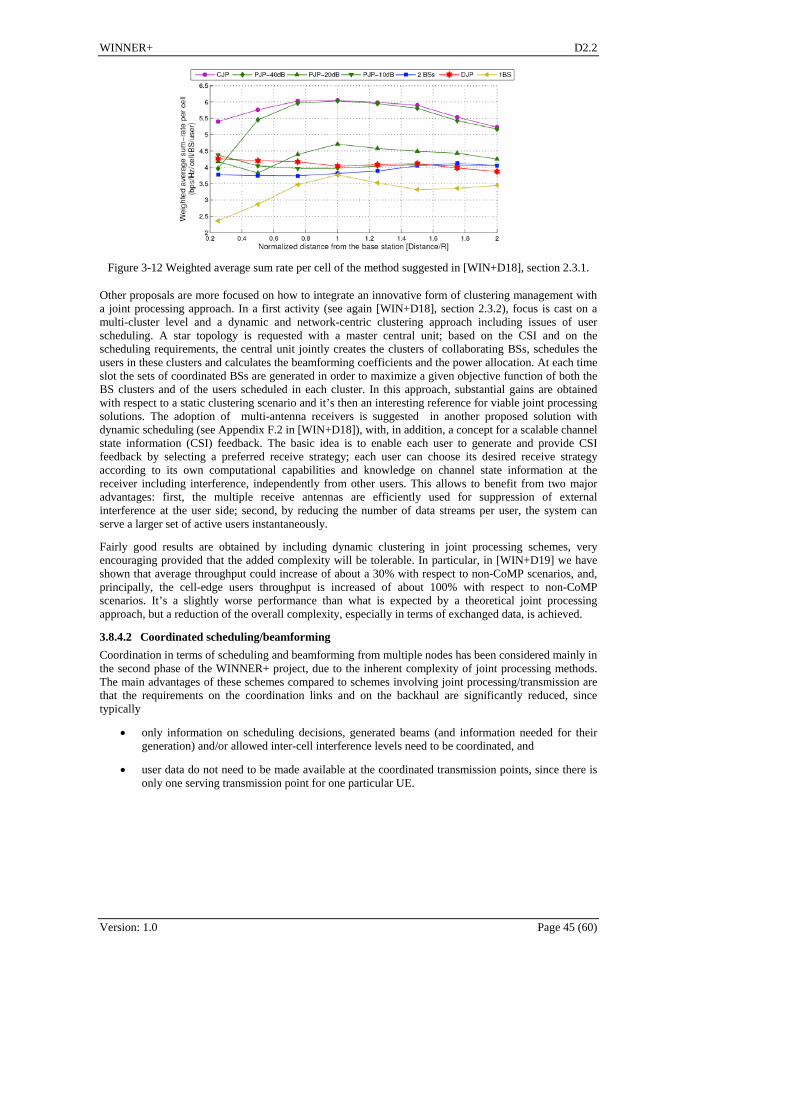
WINNER+ D2.2
Figure 3-12 Weighted average sum rate per cell of the method suggested in [WIN+D18], section 2.3.1.
Other proposals are more focused on how to integrate an innovative form of clustering management with a joint processing approach. In a first activity (see again [WIN+D18], section 2.3.2), focus is cast on a multi-cluster level and a dynamic and network-centric clustering approach including issues of user scheduling. A star topology is requested with a master central unit; based on the CSI and on the scheduling requirements, the central unit jointly creates the clusters of collaborating BSs, schedules the users in these clusters and calculates the beamforming coefficients and the power allocation. At each time slot the sets of coordinated BSs are generated in order to maximize a given objective function of both the BS clusters and of the users scheduled in each cluster. In this approach, substantial gains are obtained with respect to a static clustering scenario and it’s then an interesting reference for viable joint processing solutions. The adoption of multi-antenna receivers is suggested in another proposed solution with dynamic scheduling (see Appendix F.2 in [WIN+D18]), with, in addition, a concept for a scalable channel state information (CSI) feedback. The basic idea is to enable each user to generate and provide CSI feedback by selecting a preferred receive strategy; each user can choose its desired receive strategy according to its own computational capabilities and knowledge on channel state information at the receiver including interference, independently from other users. This allows to benefit from two major advantages: first, the multiple receive antennas are efficiently used for suppression of external interference at the user side; second, by reducing the number of data streams per user, the system can serve a larger set of active users instantaneously.
Fairly good results are obtained by including dynamic clustering in joint processing schemes, very encouraging provided that the added complexity will be tolerable. In particular, in [WIN+D19] we have shown that average throughput could increase of about a 30% with respect to non-CoMP scenarios, and, principally, the cell-edge users throughput is increased of about 100% with respect to non-CoMP scenarios. It’s a slightly worse performance than what is expected by a theoretical joint processing approach, but a reduction of the overall complexity, especially in terms of exchanged data, is achieved.
3.8.4.2 Coordinated scheduling/beamforming
Coordination in terms of scheduling and beamforming from multiple nodes has been considered mainly in the second phase of the WINNER+ project, due to the inherent complexity of joint processing methods. The main advantages of these schemes compared to schemes involving joint processing/transmission are that the requirements on the coordination links and on the backhaul are significantly reduced, since typically
only information on scheduling decisions, generated beams (and information needed for their generation) and/or allowed inter-cell interference levels need to be coordinated, and
user data do not need to be made available at the coordinated transmission points, since there is only one serving transmission point for one particular UE.
Version: 1.0 Page 45 (60)

WINNER+ D2.2
Version: 1.0 Page 46 (60)
v
control data exchange
v
control data exchange
Figure 3-13 Schematic representation of coordinated beamforming CoMP.
Coordinated beamforming can be carried out in different ways; in WINNER+, both centralized, i.e with a central entity managing the coordination process, and decentralized, i.e. where coordination is performed locally in the coordinated nodes, as well as non-codebook based and codebook based approaches are investigated. This is in compliance also with the architectures suggested at the beginning of WINNER+ activity.
In most of these schemes clustering has been considered static in general even if the evolution towards a dynamic clustering is deemed as beneficial as well. The performed studies are maybe less mature than those on joint processing since they are intended principally as an evaluation of the effectiveness of schemes where the coordination is much looser than in case of joint processing methods. The general consideration that emerges is that the simpler implementation is achieved, but currently at the expense of much poorer performances.
On the other hand, it has to be taken into account carefully an interesting property of CB-CoMP, shown in one study based on static clustering without codebook based precoding (see [WIN+D19] section 9.3.2): the enhanced robustness to mobility with respect to joint processing schemes. In particular, this study has shown that coordinated beamforming only is valuable with respect to non-CoMP scenario when ITU Urban Macro (30 kmph) model is chosen. In such a scenario, then, the performance are quite good, with an increase in both average and cell-edge users spectral efficiency of about 50%.
When adopting instead 3GPP Case 1 model the coordination in terms of beamforming does not appear to be significantly beneficial. The above mentioned study (see again [WIN+D19] section 9.3.2) reports a gain not above 20% for average spectral efficiency and no gain at all for cell-edge users. Another analysis using 3GPP Case 1 with a dynamic clustering approach and the concept of the PMI (Precoding Matrix Index, see [WIN+D18] section 2.2.3) reports a gain of about 18% in cell-edge users spectral efficiency, even if this results are to be considered still preliminary due to the assumptions made.
3.8.5 Initial CoMP trials in an indoor and outdoor deployment
Initial field trials using downlink CoMP have been conducted in the LTE-Advanced research testbed in Berlin. In addition to previusly described enabling features synchronous data exchange (see [WIN+D19]), cell-specific specific pilots, coherent CSI feedback, cooperative precoding and precoded pilots [JTW09], distributed synchronization and the use of fast virtual local area networks (VLANs) have been implemented. VLANs are used to manage data flows in the CoMP network, such as user data, feed back of CSI, and user data exchange between the base stations. The VLAN approach enabled over-the-air cooperation with physically distributed base stations (BS) and mobile terminals (here called MTs). For details see [JFJ10].

WINNER+ D2.2
Figure 3-14 Indoor (left) and distributed outdoor (right) measurement scenario.
Measurements have been conducted indoors and in several outdoor-to-indoor scenarios (see Figure 3-14). Indoors, BSs and MTs are located in the same lab. In the second scenario, we demonstrate inter-site downlink CoMP for the first time. BSs are located on the TLabs building at Ernst-Reuter-Platz and on TU Berlin main building, Straße des 17. Juni. Sites are interconnected via 1 Gbit/s Ethernet over a fiber deployed in the TU campus with a total length of 4.5 km. MTs are located in two rooms which are 25 m separated on the 11th floor at HHI. To capture the local fading statistics, MT1 moves at a speed of 3cm/s on a 5 m long track. MT2 is always at a fixed position. Measured throughput statistics are shown in Figure 3-15. Downlink CoMP is denoted as coordinated transmission and the case of interference rejection combining at the receiver side is denoted as optimum combining [WIN84]. As a reference, the throughput in isolated cells is given as well; thick lines correspond to MT1 in cell 1, thin lines to MT2 in cell 2.
Version: 1.0 Page 47 (60)
indoor outdoor-to-indoor
Comment [AO1]: What is the optimum combining?
Figure 3-15 Throughput statistics along the measurement track of MT1 for three transmission options.
In the indoor scenario, both BSs are received at both MTs with the same average power and thus the SINR is 0dB. Due to multipath propagation in the room, both the signal and the interference experience independent fading. This causes a crucial throughput situation. When moving the MT by a few cm, we can realize the situation where the desired signal is strong and the interference is in a fade. Correspondingly, the serving BS schedules data in a fraction of the bandwidth. After a few cm, we observe the reverse situation. The interference is stronger than the signal and no data are transmitted. As a result of this on-off characteristics at the cell edge, both MTs suffer from outage in 50% of the cases and the user experience is poor in general. If in such a case downlink CoMP is enabled, we observe dramatic improvements of the user experience. CoMP removes the outage at the cell edge completely. MT1 can now realize 76% and MT2 84% of the throughput in the isolated cell on average.
Next consider the inter-site scenario (see Figure 3-14 right). It is typical in the distributed multi-cell channel that the path losses are different for signal and interference. But the principal observations remain similar as in the indoor scenario. In the isolated cells, both MTs can always realize almost maximum throughput. Without CoMP, there is significant outage at least for MT1. MT2 is partly shaded from BS1 and thus it can realize a moderate throughput also without CoMP. With CoMP, MT1 realizes 50% of the isolated cell throughput on average and MT2 64%.
In summary, downlink CoMP is demonstrated for the first time in real time over the air and over 20 MHz bandwidth in a realistic deployment scenario. Essential network operator requirements have been met: distributed synchronization and inter-base-station links based on standard Ethernet. We observed large CoMP gains between factor 6 and 18 in indoor and intra- as well as inter-site scenarios. In this setup we do not consider any external interference caused from surrounding cells, i.e. we have an inter-cluster interference free condition. The unpredictable on-off characteristics of the interference channel next to the cell edge is turned into a stable continuous over-the-air link with a residual throughput variation.

WINNER+ D2.2
Version: 1.0 Page 48 (60)
3.8.6 Conclusions
Studies on CoMP have been performed extensively within WINNER+ project, representing one of the most innovative activities and leading to some relevant achievements and significant results also in trial environments (see Table 3-9 for a comprehensive overview of the main achievements). The work performed has been in compliance with the Study Item for LTE Advanced in 3GPP, often anticipating the discussion taking place there and highlighting advantages and disadvantages of the possible adoption of collaborative nodes in radio access networks.
Table 3-9 CoMP main activities.
Applicable to FDD/TDD
Applicable to UL/DL
Expected performance
(+ source)
Compatibility to LTE/
Topic for future studies
RAN Architecture for CoMP
ALL Enabler of CoMP solutions
(D1.4)
Proposed for LTE-A
To be further studied
Coordinated beamforming
FDD/TDD, DL Increase cell edge and cell average performance, in a
centralised/decentralised solution
(D1.8, partially D1.4)
Proposed for LTE-A
To be further studied
Joint processing
FDD/TDD, DL Increase of overall performance (cell throughput, ergodic sum rate, spectral
efficiency,…)
(D1.4 and D1.8)
Proposed for LTE-A
To be further studied
First practical trial
implementation
FDD/TDD, DL Practical implementation of first CoMP solutions
(D1.9, appendix F2, section 3.8.5)
Trial still ongoing
In WINNER+ a clear classification of CoMP modes has been proposed, identifying joint processing methods as very promising but somewhat complex and coordinated scheduling/beamforming as deployable initial compromise, with looser performances and complexity. An important role has been assigned in any case to clustering selection, both in static or dynamic fashion. For each scheme the impact on signalling and architecture has been outlined, suggesting some architectures that could best allow the easier implementation of CoMP solutions. Inter-eNodeB CoMP was introduced from the beginning as well.
Since CoMP, even in 3GPP, is still a topic under evaluation before a possible adoption in RAN, many possible related topics are open for future study. Apart from the first achievable solutions (Coordinated Beamforming and inter-eNodeB methods, CoMP methods for Uplink) the focus should be more on joint processing schemes, aiming to make them feasible for a RAN implementation minimizing the impacts this could bring. Clustering management is finally a topic to be further studied, in particular regarding dynamic and users driven approaches (see also chapter 5).

WINNER+ D2.2
Version: 1.0 Page 49 (60)
4. End-To-End System Performance In section 3 the selected techniques along a brief summary of their performance were given. For additional details on the performance the reader can be referred to [WIN+D19]. The end-2-end performance of these techniques adopted in LTE-A (LTE Release 9) were investigated in depth in [WIN+D42]. In this section a brief overview is given of the key performance indicators which served as an approach to investigate most of the evaluated techniques. In particular Table 4-1 reviews the Key Performance Indicators (KPIs) that were defined by ITU-R for the IMT-Advanced evaluation activity, and a selection of WINNER II KPIs.
Table 4-1: Key Performance Metrics of different simulator classes
IMT.TECH KPIs [M.2134] WINNER-II KPIs (selection)
Class I Protocol Level Simulator
Control plane latency*
User plane latency*
*: Preferably calculated analytically, but also possible to estimate in protocol-level simulations of the WINNER+ system
Investigation results with respect to protocol-related aspects, e.g., packet flow establishment time
Class II (Dynamic) System Level Simulator
Intra- and inter-frequency handover interruption time*
*: Preferably calculated analytically, but also possible to estimate in system-level simulations of the WINNER+ system
Handover-related aspects
Class III (Quasi-Static) System Level Simulator
Cell spectral efficiency
Cell edge user spectral efficiency
Link-level data rate at certain mobility classes
VoIP capacity
Cell throughput
Cell spectral efficiency
Average user throughput
Average packet delay per sector/cell
Class IV Link Level Simulator
Link-level data rate at certain mobility classes
Bit error rate / frame error rate
User data rate
Analytical Calculation
Peak spectral efficiency
Control plane latency
User plane latency
Intra- and inter-frequency handover interruption time
From the identified KPIs, a representative selection has to be made with respect to the characterization of end-to-end system performance. The following list provides a set of KPIs that might be suitable to describe the end-to-end performance of WINNER+ in a comprehensive way.
KPI 1: User and Control plane latency. For many services, this parameter determines the perceived responsiveness of the system towards user interaction. Together with the current data rate, the experienced ‘transmission speed’ is heavily influenced by this parameter for the case of interactive services such as web browsing. If possible, user and control plane latencies should be quantified separately.
KPI 2: Cell spectral efficiency. While only characterizing the user experience to a limited extent, this KPI is used in nearly all RAN system comparisons. Together with a carefully defined satisfied user criterion and deployment scenario, this parameter describes the combined performance of all relevant system components.
KPI 3: Cell edge user spectral efficiency. Often calculated with the active radio links subject to a 95th percentile path loss, this KPI characterizes the minimum performance that a RAN can deliver to the users experience the worst radio conditions. This KPI is connected to the satisfied user criterion.
KPI 4: Link-level data rate at certain mobility classes. This parameter characterizes the maximum data rate that can be assigned to a single user subject to a certain mobility class. Good

WINNER+ D2.2
Version: 1.0 Page 50 (60)
radio conditions are assumed, so that this KPI describes the experience of a favourably located user in a low network load situation.
To perform an end-to-end performance analysis with respect to the selected KPIs, an analysis should be made on how individual performance figures from simulations covering only single WINNER+ innovations (as collected in [WIN+D21]) can be combined. It is assumed that an overall system simulation (combining all relevant innovations) will not be available. The following procedure was proposed to combine individual performance gains into end-to-end KPIs..
1. It must be defined for which reference scenario the end-to-end performance shall be assessed.
2. In most assessments, individual performance gains are determined relative to a baseline system. Therefore, in order to obtain absolute KPI figures, the performance of the underlying baseline system for the chosen reference scenario must be available in absolute terms.
3. For each individual performance gain, it must be determined if it can be realized in the chosen environment, i.e., the relevance of the underlying system components for the selected reference scenario must be assessed. For each scenario, only a subset of innovative system components is typically applicable.
4. For the identified subset of performance gains, it should be determined if the gains are mutually independent, i.e. if they can be realized independently or if they are mutually exclusive. This is often a difficult task in system simulations for which the combination of innovations are not available. The effective gain of each innovative system component under the assumption that it is realized together with certain other innovations, can be expressed as a percentage arranged in a dependency matrix.
5. Performance figures with respect to all KPIs describing the end-to-end system performance (should be available for the relevant individual system components. If they are not available, they have to be estimated. Ideally, a sensitivity analysis (should be performed to characterize the consequences of estimation errors.
6. On the basis of the individual KPI figures and the analyzed dependency of gains in the selected scenario, a combination of performance figures can be carried out to obtain the end-to-end KPI.
Not for all assessed innovations, suitable metrics were used that can be translated directly into the proposed KPIs. In some cases, an estimation of KPIs might be possible on the basis of existing metrics, in other cases it might be worth modifying the simulation outputs in order to generate the relevant KPIs directly. The applicability of innovations to particular deployment scenarios still has to be verified.

WINNER+ D2.2
5. Future Directions Mobile communications have been constantly evolving for the last twenty years. With the adoption of OFDM-based systems mobile technology experienced a major step forward on which the research community is still working. From January 2004 the WINNER consortium has been paving the way towards this OFDM revolution. Specifically along the three years of WINNER+ activity this research group has made significant proposals in the topics of radio resource management, femtocells, network coding, peer to peer communications, CoMP and advanced MIMO systems. Some of these proposals were assumed in the LTE-Advanced standard whereas other topics are now under the study of the standardisation bodies for its future inclusion in upcoming releases.
The WINNER+ consortium was always aware of its man-power limitations and two special groups were established from the beginning to, first, carry out the follow up of the 3GPP and IEEE activities and, second, to identify gaps in the WINNER+ research activities and other appealing topics of research interest. The second special group has highlighted a list of research topics that should be further addressed by the research community. These are the future directions that the WP2 has identified as necessary to end up with a more complete definition of the next generation of mobile systems.
5.1 Classification of Further Research Topics
We propose to classify the changes to the specifications needed to allow these innovations in three categories:
NT (New Topic)/ Needs exhaustive research, since the topic has still not been addressed by the consortium
FR (Further Research)/ Some results have been derived but there are still some issues to be investigated
MC (Minor Changes)/ Some minor changes or steps forward to be followed by the proponent
Apart from this classification, a precedence criterion was defined to identify the urgency of each topic. This priority factor will depend on the compatibility with the legacy systems, the effort required for its implementation and the potential benefit. More exactly, the precedence criterion is defined as follows:
Version: 1.0 Page 51 (60)
BC E IPriority W W W Benefit , (5.1)
where higher mark implies higher priority of research and
WBC is the weight of Backward Compatibility being
o 1 if fully compatible with LTE/LTE-A standard
o 0.5 is compatible with minor modifications
o not compatible at all
WE is a weight related to the effort and is proportional to the expected number of man-months to succeed. In order to simplify the process a fixed set of values has been defined
o Minor effort: 3 mm
o Medium effort: 6 mm
o Major effort: 12 mm
o Huge effort: 20 mm
WI is the Immediacy weigh being proportional to the expected number of years to appear in standards. The landscape of actuation is three year, which is hence the maximum value of WI
Benefit is the potential benefit for the system (linear)

WINNER+ D2.2
Version: 1.0 Page 52 (60)
5.2 Identified Topics for Further Research
Table 5-1 summarises the set of issues identified as interesting for further research with its classification and precedence.
Table 5-1: List of topics for further research and relevance
TOPIC WBC WE WI Benefit Priority
Node synchronization for CoMP (FR) 1 3 0 3 1,00
Power control in OFDMA multi-cellular systems(NT) 1 3 0 2 0,67
Flow management in CoMP (FR) 1 6 0 3 0,50
Admission control in CoMP (NT) 1 6 0 3 0,50
Congestion control in CoMP (NT) 1 6 0 3 0,50
Buffer management and handover in CoMP (NT) 1 6 1 3 0,43
Centralised/decentralised information exchange for interference cancellation (FR) 1 6 1 3 0,43
Comparison of proposals and architecture impact
Pilot schemes for CoMP (FR) 1 6 1 3 0,43
HO from Femto to Macro cells or viceversa (FR) 1 6 0 2 0,33
CSI feedback compression schemes for CoMP, in coordinated beamforming and joint processing schemes respectively (FR) 1 12 0 3 0,25
CSI distribution schemes for CoMP, in coordinated beamforming and joint processing schemesrespectively (NT) 1 12 0 3 0,25
Collection and distribution of CQI (resulting SINR) for user scheduling in CoMP (FR) 1 12 0 3 0,25
CoMP scheme selection (decision triggers and update rates) (FR) 1 12 0 3 0,25
QoS definition and cross-layer signalling (FR) 1 6 0 1,5 0,25
Parameters and interfaces should be clarified. Also the periodicity, overheads, delays and sensibility to failures could be addressed.
Application Adaptation and Link Adaptation synchronization (FR) 1 6 0 1,5 0,25
Usage of both methods, timing, overheads
Use of adaptive beamforming for femtocell interference mitigation (NT) 1 12 0 3 0,25
How DL-HII information is going to be used
Joint scheduling and signalling in Carrier Aggregation (FR) 1 12 0 3 0,25
Overheads, reduction in control information

WINNER+ D2.2
Version: 1.0 Page 53 (60)
Signalling (CQI-PMI-RI) in Carrier Aggregation Scenarios (MC) 1 6 1 1,5 0,21
RI/PMI/CQI signalling for relays (NT) 0,5 3 1 1,5 0,19
Retransmission schemes in CoMP (NT) 1 12 0 2 0,17
Resource allocation in relay networks (FR) 0,5 12 1 4 0,15
Time multiplexing, control information, scheduling decisions, analysis of alternatives and different performances
Control interchange, overheads, timing
Usage of Carrier Aggregation for Relaying purposes (NT) 0,5 12 1 3 0,12
Self-Organisation, dynamic bandwidth allocation for relays, LTE users and LTE-A users
Peer to peer communication implementation (NT) 0,5 20 3 5 0,11
Is going to be included? MAC operation, multiplexing, interference cancellation...
Femtocell backhaul using relaying (NT) 0,5 12 1 2 0,08
Identify the implications of femto-relaying with outdoor-to-indoor equipments acting as gap-fillers
MBMS operation (FR) 0,5 12 1 2 0,08
Repair services, multiplexing of unicast and multicast services, control information management
Usage of Application Layer coding and Channel Coding relaxing (NT) 0,5 12 2 2 0,07
Finally, the main open trends in the innovations areas of WINNER+ are briefly sketched in the following.
Advanced Antenna Systems
Improved assessment of the proposed MU-MIMO precoding techniques is important for future research. The additional gains from the proposed methods should be more thoroughly evaluated against the existing methods available, e.g. in standards. Furthermore, the vulnerability of different techniques to CSI uncertainties (estimation errors, feedback delays) should be better clarified.
More focus should be put on generic inter-cell interference aware MU-MIMO precoding solutions allowed by the TDD mode . Large part of WINNER+ work has focused on FDD scenarios with quantized CSI feedback. However, the largest gains are available from (coordinated) MU-MIMO processing with accurate CSIT (TDD) in local area scenarios with low mobility. Therefore, more focus on local area solutions should be given. However, there are important practical difficulties associated with the solutions relying on the channel reciprocity that have to be carefully studied, such as the calibration of the RF chains and the impact of channel estimation and quantization errors on the performance of the algorithms.
The optimal linear multiuser precoding and resource allocation strategies for different design criteria are still not known in general. Very efficient approximate solutions exist but they tend to be computationally complex. Thus, more work on less complex linear precoding algorithms is still needed.
Coordinated MultiPoint
Many possible related topics are open for future study in the framework of CoMP activity. The first achievable solutions are foreseen to be Coordinated Beamforming and intra/inter-eNodeB methods or CoMP methods for Uplink. Here studies on the impacts on the architecture are of fundamental relevance, especially because the achievable performance could not worth huge modifications on existing RAN layouts.

WINNER+ D2.2
Version: 1.0 Page 54 (60)
In the future, then, the focus should be more on joint processing schemes, aiming to make them feasible for a RAN implementation while minimizing the impacts this could bring. Their expected performances are indeed more significant with respect to those of coordination at beamforming/scheduling level.
Meanwhile, for any coordination possibly introduced, the clustering management will be of fundamental relevance, in particular including MAC coordination. Current studies are heading towards a dynamic control of cluster patterns.
Relaying
There is still a need for improved understanding of the benefit of relaying. Relaying can clearly improve the coverage and they can redistribute the capacity in the cell. It is less clear if in-band relays can be included in a cellular system to also improve the overall spectral efficiency. In a cellular system using CoMP, the role of relays as a tool to improve cell-edge performance might be less of an importance as well. The work within the WINNER+ project has not allowed drawing a clear conclusion on these questions. The next steps would be cooperative relaying in cellular systems with and without CoMP among eNBs, multi-hop (more than two) communications, moving relays (in train or buses) or even user terminal acting as relays because from the topology point of view, we still have many things to improve: the way energy of signals is spent if assuming multi-hop communications can be largely improved.
Advanced RRM
WINNER+ activity is not the end point of the research in the three different areas encompassed by the ARRM concept. Much work is still needed in the resource management part, including beam selection mechanism, coordination among base stations and selection of users in multi-user scenario. The frequency-time-space-transmitter selection is a quite hard optimization problem that has been only tackled in WINNER+ in a separate manner. Concerning QoS management, there are a lot of procedures to be designed concerning IMS interworking and real time flow management. The VoIP scenario must be studied with high priority since it poses most tight constraints to the resource management. Other topics like resource management in relaying and peer-to-peer scenarios are areas where small activity has occurred but needs further research in the coming years before its complete adoption in technological standards.
Spectrum
Femtocells are not a mature technology. There are still issues regarding interference; especially femto-to-femto interference – even if it can be partially solved by beacons – still limits the performance. The solutions to the problem have to be decentralized, and this is the major challenge. Another important problem to be solved is mobility management. This includes handovers to and from femtocells. While this has not been studied in WINNER+, in practical networks the problem has to be solved.

WINNER+ D2.2
Version: 1.0 Page 55 (60)
6. Conclusions This deliverable made the final innovations techniques selection for IMT-advanced and beyond. The selection of the most promising techniques was based on their performance, potentials, and compliance with standards. Moreover the selected innovations were placed within the appropriate deployment/usage/user scenarios.
The deliverable started with a brief definition of the term "scenario". The classification of innovation techniques within the framework of scenarios allowed a better understanding and clarification under which circumstances such techniques fit best, and consequently can be used. The term ‘scenario’ was used in the classical known sense and was subdivided into several cases, namely the following: user scenario, usage scenario, traffic load scenario and deployment scenario.
Afterward an extensive description of the selected innovations in the following areas was given: Resource Allocation, Carrier Aggregation, Femtocells, Relaying, Network Coding, Multi-User Multiple-Input-Multiple-Output (MU-MIMO) systems and Channel State Information (CSI) acquisition, Quality of Service (QoS) control, and Coordinated Multipoint (CoMP).
Resource allocation is a key factor influencing the system performance. An efficient and flexible scheduling and spectrum allocation process improves the achieved spectral efficiency. Three out of five innovations in resource allocation have been deemed the most promising. These innovations deals with the Decentralised interference avoidance using Busy Burst, Spectrum sharing form game-theory perspective and Efficient MBMS. They provide a significant performance gain at a relatively small cost of introducing additional signalling measures. Decentralised interference avoidance was deemed to the resource allocation technique with the greatest perspectives for improvement.
Carrier Aggregation has been deeply assessed from different points of view; mainly from physical and MAC layers. From the physical layer perspective the improvement achieved with LDPC was mostly limited to 0.5 dB. Provided that LDPC are not LTE-compatible, its inclusion in WINNER+ was not recommended. From the MAC layer perspective a significant advantage of non-contiguous carrier aggregation over contiguous aggregation has been observed, mostly due to the higher spectral diversity of the former strategy. Hence a proper allocation of frequencies in LTE-A is recommended in order to make the most of the diversity gain offered by the spread spectrum.
Femtocells are a promising method to increase system capacity of a cellular network. Due to their uncoordinated nature, minimal changes are needed in the macro network. On the other hand, if some amount of coordination is allowed, the performance can be improved by more advanced interference control and channel allocation methods. The revised femtocell innovations in WINNER+ were divided into two categories: coordinated and uncoordinated. In the coordinated approach, the interference from the macro network to the femtocell is avoided by extending the ICIC mechanism to the femtocells. Game theoretical approach is then used to further optimize the resource usage. In the uncoordinated case, there is no signalling between macro and femto networks. Instead, femto-to-macro interference is avoided by using TDD on UL band in the femtocell. In this way, when the distance to the nearest MBS is large enough, the femtocell does not cause any interference.
The relaying work carried out within the project has not allowed drawing a clear conclusion on the coverage and capacity improvements relays can bring in specific area of the network yet. However, it did help understanding the problems and concentrate on most important issues. The 3GPP is already on the right track with its implementations of relays, and it will become more and more difficult to extract the research field out of such blindness this dynamic partnership generates. It is expected that the next steps would be multi-hop (more than two) communications, moving relays (in train or buses) or even user terminal acting as relays.
Network Coding is one of the promising techniques for IMT-Advanced. It was investigated mainly in the uplink aspect using fixed relay nodes. It was showed that non-binary network coding multiple-relay scenario can provide a diversity order of 3, but at the expense of major signalling and architecture changes imposed on the network. Relay selection and user grouping in a relay multiple access scenario showed that up to 70% gain in terms of system capacity can be obtained. Moreover D2D communication is also a very promising area. It was shown that in an ideal scenario where D2D communication is used as an underlay to an LTE network leads up to 7-fold increase in the cell throughput. The main constraint for such technique (i.e. D2D communication) is the interference it causes to the cellular network. Hence more studies in this field are needed to make its integration in the wireless system more mature.
The Advanced Antenna innovations Schemes introduced in WINNER+ focus mostly on seeking for system performance improvements from advances in the acquisition of CSIT – short term or long-term –

WINNER+ D2.2
Version: 1.0 Page 56 (60)
via new signaling and estimation solutions. Most of the contributions consider relatively low velocity terminals allowing for the utilisation of CSI at the transmitter. The preferred multi-antenna transmission methods both in rural/wide area and urban/local area scenarios with relatively low velocity were provided. Users located in environments with low angular spread, including rural and wide area scenarios can be served by adaptive beamforming or code-book-based precoding relying mostly on statistical CSI and simple CQI feedback. In environments with high angular spread such as urban local area scenario there is a possibility to have more reliable instantaneous CSI via uplink sounding, thus allowing for the use of more sophisticated MU-MIMO precoding schemes.
Providing QoS on the wireless link involves cross-layer aspects. While a conventional system design requires a high load margin to handle peak traffic with QoS requirements, a sophisticated cross-layer design allows to reduce the load margin so that more users can be served with a required QoS. A number of innovations have been developed within WINNER+; however these activities were focused on specific aspects, such as scheduling for mixes of different service classes. An interesting topic for further research would be to combine all these individual approaches into one holistic framework for QoS support.
Studies on CoMP have been performed extensively within WINNER+ project, representing one of the most innovative activities and leading to some relevant achievements and significant results also in trial environments. A clear classification of CoMP modes has been proposed, identifying joint processing methods as very promising but somewhat complex and coordinated scheduling/beamforming as deployable initial compromise, with looser performances and complexity. An important role has been assigned to clustering, both in static or dynamic fashion. Apart from the first achievable solutions (Coordinated Beamforming and inter-eNodeB methods, CoMP methods for Uplink) the focus should be more on joint processing schemes, aiming to make them feasible for a RAN implementation. Clustering management is finally a topic to be further studied, in particular regarding dynamic and users driven approaches.
Finally the gaps in the WINNER+ research activities and other appealing were identified. These are the future directions that the WINNER+ consortium identified as necessary to end up with a complete definition of next generation mobile system. It was proposed to classify the changes to the specifications needed to allow these innovations in three categories: Needs exhaustive research, requires further investigating, and necessitates minor changes.
Hitherto the scenario approach taken herein in order to classify the ideal and suitable environment was classical. A different and more radical approach is recommended in order to anticipate futuristic user, usage and usability behaviours in a communication system. Scenarios shall be tackled from in a multi-dimensional way and from several angles. It shall take into account the integration of new techniques and the facts created in the ground due to the presence of more and more heterogonous networks. To cite the least, it shall be envisaged scenarios
where multi-communication (e.g. cellular, satellite, vehicular, etc..) systems communicate,
such as classification between central and non-central system is common,
where moving radio node plays a pivotal role,
such as machine to machine communication,
where the energy optimization is the equation to solve,
where cognitive radio or spectrum sharing/coordination are an integral part of any system.
At last it is desired that ongoing EU projects in the wireless communications community such as ARTIST4G [ART10] and EARTH [EAR10] pave the way to a define a clear scenariolistic vision based on the lessons learned the last decade. Hence making a continuation of the work initiated in WINNER in 2004.

WINNER+ D2.2
Version: 1.0 Page 57 (60)
7. References [3GPP25820] 3GPP TR 25.280, “3G Home NodeB Study Item Technical Report,” v.8.2.0. September
2008.
[3GPP36300] 3GPP TR 36.300, "Evolved Universal Terrestrial Radio Access (E-UTRA) and Evolved Universal Terrestrial Radio Access Network (E-UTRAN); Overall description", V8.5.0, May 2008.
[3GPP36814] 3GPP TR 36.814, "Further Advancements for E-UTRA Physical Layer Aspects", V9.0.0, Mar 2010.
[3GPPPAN09] 3GPP R1-091165 “Discussion on PUCCH coordination for UL CoMP”, Panasonic, 3GPP TSG RAN WG1 Meeting #56bis, Mar 2009
[ACL+00] R. Ahlswede, N. Cai, S.-Y. R. Li and R. W. Yeung, Network information flow, IEEE Trans. Information Theory, July 2000.
[ART10] ARTIST4G, FP7 Project, https://ict-artist4g.eu/.
[BRR09] T. Beniero, S. Redana, J, B. Raaf, Effect of Relaying on Coverage in 3GPP LTE-Advanced, IEEE Vehicular Technology Conference (VTC) Spring, 2009, April 2009.
[CCK09] Emilio Calvanese-Strinati, Giorgio Corbellini, Dimitri Kténas, “HYGIENE Scheduling for OFDMA Wireless Cellular Networks”, IEEE 69th Vehicular Technology Conference (VTC) Spring 2009, 26–29 April 2009, Barcelona, Spain.
[CG79] T. M. Cover and A. A. El Gamal, “Capacity theorems for the relay channel,” IEEE Trans. Inform. Theory, vol. IT-25, pp. 572–584, Sept.1979.
[CKL06] Y. Chen, S. Kirshore, and J. Li, “Wireless diversity through network coding,” in Proceedings of IEEE Wireless communications and networking conference, 2006.
[EAR10] EARTH, FP7 Project, INFSO-ICT-247733, https://www.ict-earth.eu/.
[GAH08] B. Ghimire, G. Auer and H. Haas, “Busy Bursts for Trading-off Throughput and Fairness in Cellular OFDMA-TDD,” EURASIP Journal on Wireless Communications and Networking, 2008.
[HFG09] C. Hoymann, L. Falconetti, R. Gupta, “Distributed Uplink Signal Processing of Cooperating Base Stations based on IQ Sample Exchange”, ICC 2009, Dresden, June 14-18, 2009
[IEEE16mCA] IEEE 802.16 Broadband Wireless Access Working Group, “Considerations for Carrier Aggregation”, IEEE C802.16m-08/991, Sep. 5, 2008.
[IEEE16mSDD] IEEE 802.16 Broadband Wireless Access Working Group, “IEEE 802.16m System Description Document,” IEEE 802.16m-09/0034r2, Sep 24, 2009.
[JTW09] V. Jungnickel, L. Thiele, T. Wirth, T. Haustein, S. Schiffermüller, A. Forck, S. Wahls, S. Jaeckel, S. Schubert, H. Gäbler, C. Juchems, F. Luhn, R. Zavrtak, H. Droste, G. Kadel, W. Kreher, J. Mueller, W. Stoermer, G. Wannemacher, “Coordinated Multipoint Trials in the Downlink,” Proc. IEEE Globecom BWAWS Workshop '09, 2009.
[JFJ10] V. Jungnickel, A. Forck, S. Jaeckel, F. Bauermeister, S. Schiffermueller, S. Schubert, S. Wahls, L. Thiele, T. Haustein, H. Droste, G. Kadel, “Cell-Edge Trials using Coordinated Multi-Point Transmission in the Downlink”, accepted for publication in Proc. IEEE PIMRC 2010 Workshop on Distributed Wireless Networks.
[LJS06] P. Larsson, N. Johansson, and K.-E. Sunnel, Coded Bi-Directional Relaying, Proc. of IEEE VTC 2006 Spring, pp. 851-855
[LTW04] J. N. Laneman, D. N. C. Tse, G. W. Wornell, "Cooperative Diversity in Wireless Networks: Efficient Protocols and Outage Behavior" IEEE Transactions on Information Theory, VOL. 50, NO. 12, December 2004.
[LRR09] E. Lang, S. Redana, B. Raaf, “Business Impact of Relay Deployment for Coverage Extension in 3GPP LTE-Advanced”, LTE Evolution Workshop @ ICC 2009, 14-18 June 2009
[Meu71] E. C. Van der Meulen "Three-Terminals Communication Channels". Adv. Appl. Prob. Vol. 3. pp120-154. 1971.

WINNER+ D2.2
Version: 1.0 Page 58 (60)
[Meu77] Edward C. Van der Meulen, "A Survey of Multi-Way Channels in Information Theory. 1961-1976". Invited paper. IEEE Transactions on Information Theory. Vol. IT 23, No. 1, January 1977.
[MAR07] P. Marsch and G. Fettweis, “A Framework for Optimizing the Uplink Performance of Distributed Antenna Systems under a Constrained Backhaul,” June 2007, pp. 975–979.
[M.2134] ITU-R, M.2134, “Requirements related to technical performance for IMT Advanced radio interface(s)”.
[MOS08] J. Manssour, A. Osseiran and S. Ben Slimane, “Wireless Network Coding in Multi-Cell Networks: Analysis and Performance”, International Conference on Signal Processing and Communication Systems, ICSPCS’2008, Gold Coast, Australia, December 2008.
[MOS09] J. Manssour, A. Osseiran and S. Ben Slimane, “Opportunistic Relay Selection for Wireless Network Coding”, IEEE MICC 2009 , Kuala Lumpur, Malaysia, December 2009.
[Nak09] T. Nakamura (3GPP TSG-RAN Chairman), “Proposal for Candidate Radio Interface Technologies for IMT-Advanced Based on LTE Release 10 and Beyond (LTE-Advanced),” presentation in ITU-R WP 5D 3rd Workshop on IMT-Advanced, Oct 15 2009.
[SaA09] Andreas Saul and Gunther Auer, “Multiuser Resource Allocation Maximizing the Perceived Quality,” EURASIP Journal on Wireless Communications and Networking, vol. 2009, Article ID 341689, 15 pages, 2009. doi:10.1155/2009/341689.
[SAP08] SAP White Paper – Toward a European Strategy for the Future Internet, RQ 26175 (08/09),2008,http://www.europeansoftware.org/documents/SAP_WP_FutureInternet.pdf.
[SHW08] R. Schoenen, R. Halfmann, B. H. Walke, “An FDD Multihop Cellular Network for 3GPP-LTE”, VTC 2008, 11-14 May 2008, pp. 1990-1994 ].
[SL05] A. So, B. Liang, “Effect of Relaying on Capacity Improvement in Wireless Local Area Networks”, WCNC 2005, 13-17 March 2005, Vol. 3, pp. 1539-1544;
[SW07] R. Schoenen, B.H. Walke, “On PHY and MAC Performance of 3G-LTE in a Multi-Hop Cellular Environment”, WiCom 2007, 21-25 Sept. 2007, pp. 926 – 929;
[SWB06] A. Shukla, B. Willamson, J. Burns, E. Burbidge, A. Taylor and D. Robinson, “QINETIQ/06/01773 A study for the provision of aggregation of frequency to provide wider bandwidth services,” August 2006.
[VEN07] S. Venkatesan “Coordinating base stations for greater uplink spectral efficiency in a cellular network,” in Proc. PIMRC, 2007
[WIN84] J. Winters. Optimum Combining in Digital Mobile Radio with Cochannel Interference. IEEE Journal on Selected Areas in Communications, 2(4):528--539, 1984.
[WIN+PD] WINNER+ Project Description. Celtic Full Project Proposal-CALL 5.
[WIN+D11] CELTIC project CP5-026 WINNER+, “D1.1 Initial Report on Advanced Radio Resource Management,” Jan. 2009.
[WIN+D12] CELTIC project CP5-026 WINNER+ “D1.2 Initial Report on System Aspects of Flexible Spectrum Use,” Jan. 2009.
[WIN+D13] CELTIC project CP5-026 WINNER+ “Innovative concepts in Peer-to-Peer and Network Coding,” Jan. 2009.
[WIN+D14] CELTIC project CP5-026 WINNER+ “D1.4 Initial Report on Advanced Multiple Antenna Systems” Jan. 2009.
[WIN+D15] Celtic CP5-026 WINNER+, Intermediate Report on System Aspect of Advanced RRM, Deliverable D1.5, November 2009, http://projects.celtic-initiative.org/winner+/deliverables_winnerplus.html.
[WIN+D16] Celtic CP5-026 WINNER+, Intermediate Report on Flexible Spectrum Use, Deliverable D1.6, November 2009, http://projects.celtic-initiative.org/winner+/deliverables_winnerplus.html
[WIN+D17] Celtic CP5-026 WINNER+, Intermediate Report on Advanced Multiple Antenna Systems, Deliverable D1.7, November 2009, http://projects.celtic-initiative.org/winner+/deliverables_winnerplus.html

WINNER+ D2.2
Version: 1.0 Page 59 (60)
[WIN+D18] Celtic CP5-026 WINNER+, Intermediate Report on Coordinated Multipoint and Relaying in the Framework of CoMP, Deliverable D1.8, November 2009, http://projects.celtic-initiative.org/winner+/deliverables_winnerplus.html
[WIN+D19] Celtic CP5-026 WINNER+, Final Innovation Report, Deliverable D1.9, April 2010.
[WIN+D21] Celtic Project CP5-026 WINNER+ "D2.1 Preliminary WINNER+ System Concept", May 2009
[WIN+D32] Celtic Project CP5-026 WINNER+, “D3.2 Aspects of WINNER+ Spectrum Preferences”, May 2009.
[WIN+D41] CELTIC project CP5-026 WINNER+ “D4.1 Results of Y1 proposed candidate proof-of-concept evaluation” Feb. 2009.
[WIN+D42] Celtic CP5-026 WINNER+, “Final conclusions on end-to-end performance and sensitivity analysis”, Deliverable D4.2, July 2010, http://projects.celtic-initiative.org/winner+/deliverables_winnerplus.html
[WIN+10EVAL] Final Evaluation Report from WINNER+ on the IMT-Advanced Proposal in Documents IMT-ADV/6 IMT-ADV/8 AND IMT-ADV/.
[WIN2D6137] IST-4-027756 WINNER II, Deliverable D6.13.7, Test Scenarios and Calibration Cases Issue 2, December 2006; or in IST-4-027756 WINNER II, Deliverable D1.1.1, WINNER II interim channel models, November 2006.
[WIN2D351] IST-4-027756 WINNER II, Deliverable D3.5.1, Relaying concepts and supporting actions in the context of CGs, October 2006;
[WIN2D352] IST-4-027756 WINNER II D3.5.2, Assessment of relay based deployment concepts and detailed description of multi-hop capable RAN protocols as input for the concept group work, June, 2007;
[WIN2D353] IST-4-027756 WINNER II D3.5.3, Final assessment of relaying concepts for all Concept Groups scenarios under consideration of related WINNER II L1 and L2 protocol functions, September 2007
[WIN2D61314] IST-4-027756 WINNER II D6.13.14‚“WINNER II System Concept Description“, Dec 2007.
[X+08] Ming Xiao et. al, “Optimal Decoding and Performance Analysis of a Noisy Channel network with Network Coding,” Accepted to IEEE Transactions on Communications, April 2008.
[XS09] Ming Xiao and Mikael Skoglund, “M-user Cooperative Wireless Communications Based on Nonbinary Network Codes,” IEEE Information Theory Workshop on Networking and Information Theory, June 2009.

WINNER+ D2.2
A. Simulation scenario for CoMP Considering the evaluations performed to evaluate CoMP (see Section 3.8) even if a common platform to perform shared simulations has not been adopted in WINNER+ studies on CoMP, a reference scenario has been presented in [WIN+D21] section 5.3.3.1, based on the main assumptions that are reported in the Table A-1.
Table A-1 CoMP simulations scenario.
Needed in coherent approaches. To be evaluatedhase coherence inoordinated nodes
Users data for joint processing in various types; for coordinated BF various types of dataData Exchange among Nodes
Yes. In most cases already guaranteedarrier frequencyynchronization
Full CSI-T; full CSI-RStudied also the case with reduced CSI and estimated performance in non ideal cases
Channel stateInformation
4-element ULA in Nodes2-element ULA in UEs
Minimal ntenna configuration
Intra-cell and Inter-cell; Centralized and Decentralized; Clusteringrchitectures
3GPP SCM [3GPP25814] in the framework of 3GPP case 1Urban Macro /Urban micro
hannel model
Average cell throughputCell borders users throughput Ergodic Sum Rate, Minimum Sum Power
valuation Metrics
Both coherent and non-coherent (coordinated scheduling)oordination approaches
Downlink (Uplink easier but very few contributions in WINNER+)oordination Link
SAEeference Architecture
Pc
Cs
A
A
C
E
C
C
R
LTE, LTE-AdvReference System
Version: 1.0 Page 60 (60)