
Enabling Service Adaptability with Versatile Anycast - Globule
20
Enabling Service Adaptability with Versatile Anycast M. Szymaniak † , G. Pierre † , M. Simons-Nikolova ‡ , M. van Steen † Vrije Universiteit Amsterdam † , Philips Research Labs Eindhoven ‡ {michal,gpierre,steen}@cs.vu.nl, [email protected] Abstract We present versatile anycast, which allows a service running on a varying collection of nodes scattered over a wide-area network to present itself to the clients as one running on a single node. Providing a single logical address enables the client-side software to preserve the traditional service access model based on single access points. At the same time, the dynamic composition of anycast groups implemented by versatile anycast enables the server-side service infrastructure to evolve and adapt to changing network conditions. We implement versatile anycast using Mobile IPv6, which decouples the logical addresses of mobile nodes from their physical location. We exploit that decoupling to implement logical service addresses that are not bound to any physical nodes, and employ standard MIPv6 mechanisms to dynamically map each such address onto individual service nodes. Our solution enables a service to transparently hand off clients among the service nodes at the network level while preserving optimal routing between the clients and the service nodes. We demonstrate that the overhead of versatile anycasting is very low. In particular, the client-perceived handoff time is shown to be a linear function of the latencies among the client and the service nodes partici- pating in the handoff. 1 Introduction Grid applications are changing. The Grid was created as a distributed super-computer hosting standalone parallel computations [1]. Such computations can often be managed by a single “coordinator” node responsible for submitting node allocation requests to the grid scheduler, distributing the application input to the allocated nodes, and retrieving the results. The coordinator then becomes the natural entry point to communicate with the grid application. However, grid applications increasingly often adopt a different model in which they provide services to one or more external components [2]. By means of standard SOAP-based interfaces, grid services can now be used by other applications running either inside or outside of the grid. An important property of such services is that they might be instantiated dynamically to provide the required quality of service. For example, a service might dynamically adapt its capacity to guarantee consistent response times to its users. This typically involves changes in the number and location of machines running service instances. Another reason for a grid service to change its hardware base is the evolution of service implementation. For example, a regular Web service might migrate from a single node to a distributed grid infrastructure in order to benefit from advanced adaptation and capacity planning features. Such a migration is likely to result in significant design changes in the architecture of the service. However, a coordinator-based service access model restricts the type of possible architectural changes, as it relies on fixed coordinators to act as gateways to the service. The need for service adaptability often conflicts with the traditional service access model implemented by clients. To easily integrate a grid service into their own applications, clients typically require that the service maintains a single stable access point implementing a SOAP interface. On the other hand, the service needs the ability to change its internal organization at will, preferably transparently to the clients. To satisfy both these requirements, we propose to decouple the conceptual communication model exploited by grid clients from the actual service implementation. The idea is to identify a grid service by a single stable logical network address. Similar to the addresses of traditional access points, a logical address can always be 1
Transcript of Enabling Service Adaptability with Versatile Anycast - Globule

Enabling Service Adaptability with Versatile Anycast
M. Szymaniak†
, G. Pierre†
, M. Simons-Nikolova‡
, M. van Steen†
Vrije Universiteit Amsterdam†
, Philips Research Labs Eindhoven‡
{michal,gpierre,steen}@cs.vu.nl, [email protected]
Abstract
We present versatile anycast, which allows a service running on a varying collection of nodes scatteredover a wide-area network to present itself to the clients as one running on a single node. Providing a singlelogical address enables the client-side software to preserve the traditional service access model based on singleaccess points. At the same time, the dynamic composition of anycast groups implemented by versatile anycastenables the server-side service infrastructure to evolve and adapt to changing network conditions.
We implement versatile anycast using Mobile IPv6, which decouples the logical addresses of mobile nodesfrom their physical location. We exploit that decoupling toimplement logical service addresses that are notbound to any physical nodes, and employ standard MIPv6 mechanisms to dynamically map each such addressonto individual service nodes. Our solution enables a service to transparently hand off clients among theservice nodes at the network level while preserving optimalrouting between the clients and the service nodes.
We demonstrate that the overhead of versatile anycasting isvery low. In particular, the client-perceivedhandoff time is shown to be a linear function of the latenciesamong the client and the service nodes partici-pating in the handoff.
1 Introduction
Grid applications are changing. The Grid was created as a distributed super-computer hosting standalone parallelcomputations [1]. Such computations can often be managed bya single “coordinator” node responsible forsubmitting node allocation requests to the grid scheduler,distributing the application input to the allocatednodes, and retrieving the results. The coordinator then becomes the natural entry point to communicate with thegrid application.
However, grid applications increasingly often adopt a different model in which they provideservices to oneor more external components [2]. By means of standard SOAP-based interfaces, grid services can now be usedby other applications running either inside or outside of the grid.
An important property of such services is that they might be instantiated dynamically to provide the requiredquality of service. For example, a service might dynamically adapt its capacity to guarantee consistent responsetimes to its users. This typically involves changes in the number and location of machines running serviceinstances.
Another reason for a grid service to change its hardware baseis the evolution of service implementation.For example, a regular Web service might migrate from a single node to a distributed grid infrastructure inorder to benefit from advanced adaptation and capacity planning features. Such a migration is likely to result insignificant design changes in the architecture of the service. However, a coordinator-based service access modelrestricts the type of possible architectural changes, as itrelies on fixed coordinators to act as gateways to theservice.
The need for service adaptability often conflicts with the traditional service access model implemented byclients. To easily integrate a grid service into their own applications, clients typically require that the servicemaintains a single stable access point implementing a SOAP interface. On the other hand, the service needs theability to change its internal organization at will, preferably transparently to the clients.
To satisfy both these requirements, we propose to decouple the conceptual communication model exploitedby grid clients from the actual service implementation. Theidea is to identify a grid service by a single stablelogical network address. Similar to the addresses of traditional access points, a logical address can always be
1

used to communicate with the service. However, the difference is that logical addresses are not bound to anyphysical node. Instead, each such address can be dynamically mapped to any grid node while the service retainsfull and timely control of this mapping.
Decoupling the communication model from the service implementation has several advantages. First, itallows the service architecture to evolve without being constrained by its original design, which improves serviceadaptability. Second, as upgrading the service infrastructure does not affect client-side applications, they mightbe implemented by multiple vendors independent of the service operator. Such an approach has been followedby many successful Internet services, including the Web andBitTorrent [3, 4].
Assigning a logical address to a group of physical nodes comes close to anycasting. Anycast was proposedas a routing and addressing scheme by which traffic sent to an anycast address automatically reaches some nodewithin the addressed group [5]. This functionality is typically implemented by means of routing algorithms,which cause Internet routers to redirect anycast traffic according to some network proximity metric.
However, efficient usage of resources available within a grid service depends on many factors other thannetwork proximity. For example, differences in the utilization of individual grid nodes make it necessary toroute client requests according to additional metrics suchas network bandwidth and cpu load. Also, as theutilization and availability of service nodes changes dynamically, the routing decisions must have immediateeffects to prevent client requests from being redirected tooverloaded or unavailable nodes. Finally, efficientanycasting should not introduce significant overhead compared to unicast communication.
The limitations of routing-based anycast resulted in proposing many alternative anycast implementations.They provide anycast functionality using either front ends, DHTs, DNS-based redirection, or anycast-awareclient-side software. However, as we discuss in a previous study, none of these implementations eliminates allthe limitations entirely [6].
Our solution lies in the design ofversatile anycast, in which each anycast group retains full and timely con-trol over how the incoming traffic is switched among the individual nodes within that group. At the same time,our implementation does not incur any significant communication overhead compared to unicast communica-tion. These two properties enable us to implement the logical addresses of grid services as anycast addressesprovided by versatile anycast.
We implement versatile anycast by exploiting the logical separation of network addresses that Mobile IPv6assigns to mobile nodes. In principle, each Mobile IPv6 nodehas a permanent “home” address, which identifiesthe node, and a temporary “care-of” address, which identifies the node’s current location. Mobile IPv6 ensuresthat network traffic sent to home addresses is transparentlyforwarded to their care-of counterparts. To this end,it relies on clients communicating with mobile nodes to translate between home- and care-of addresses.
This article demonstrates that the very same translation mechanisms can also be used to equip grid serviceswith logical addresses. In that case, a service as a whole canbe perceived by its clients as some fictitiousmobile node, regardless of the current composition of the service infrastructure. The logical address of theservice is implemented as the home address of the fictitious mobile node, whereas the addresses of individualnodes within the service infrastructure can be treated as potential care-of addresses of that node. Using traffic-switching mechanisms provided by Mobile IPv6, a grid service can transparently handoff its clients to individualnodes at which it is hosted. Note that implementing logical addresses in the network layer allows for leavingthe higher layers of client-side software untouched. This means in particular that with a relatively small numberof server-side modifications, our scheme can be incorporated into any service exploiting the traditional accessmodel based on single access points, including those that already exist.
A preliminary discussion on the usefulness of versatile anycast has been reported in [6]. However, it onlycontains a high-level description of the functionality, and no performance evaluation. The contributions of thepresent article are threefold: (i) a full description of versatile anycast implementation; (ii) details on the integra-tion of versatile anycast with higher-level protocols suchas TCP; and (iii) an in-depth performance evaluationand discussion on various possible optimizations. None of these contributions have been reported in [6].
The remainder of this article is structured as follows. Section 2 describes the architecture of grid servicesequipped with logical addresses, and demonstrates how suchaddresses enable service adaptability. Section 3presents related work and explains why it is hard to provide logical addresses using current techniques. Section 4describes how grid services can exploit versatile anycast to implement logical addresses, and how versatileanycast can be implemented using Mobile IPv6. Finally, Section 5 evaluates the performance of our anycastimplementation, and Section 7 concludes.
2

����������������������������������������
����������������������������������������
������������������������
������������������������
���������������
���������������
����������������������������������������
����������������������������������������
������������������������
������������������������
���������������
���������������
���������������������
���������������������
���������������������
���������������������
����������������������
����������������������
����������������������
����������������������
Client 1
Client 2
Service Node A
Service Node B
LogicalAddress
Grid Service
Figure 1: Accessing grid services via logical addresses
2 System Model
2.1 Overview
Introducing logical addresses enables grid services to decouple the client-side software development from theservice-side infrastructure design. Figure 1 depicts the conceptual service access model. In principle, nothingchanges from the perspective of the service clients, which access the service at its logical address just like theytraditionally communicate with the addresses of physical service gateways.
However, the logical address is not bound to any physical node. It is therefore the responsibility of theservice to ensure that all the traffic heading to that addressis routed to the physical address of one or morenodes within the service infrastructure. To this end, the service transparently maps the logical address onto thephysical addresses of the service nodes. As long as the mapping mechanism enables the service to dynamicallyswitch the clients among the service nodes, each of these nodes can join and leave the service infrastructure atwill, allowing for service adaptability.
2.2 Properties
The functionality of logical addresses requires them to have a number of properties. The first fundamental one istransparency, which means that using logical addresses cannot mandate any changes to the client-side software,which must be able to communicate with grid services via logical addresses just like via their physical coun-terparts. The second fundamental property is efficiency, which means that accessing grid services via logicaladdresses should not incur significant overhead compared todoing so via physical addresses. In particular, theclients should be able to communicate efficiently with a gridservice even when service nodes are scattered overa wide-area network, which is often the case with massively popular network services [7].
Another group of properties is related to the mapping of logical addresses onto physical nodes. For example,efficient usage of service nodes requires fine-grain controlover which clients are redirected to which nodes.This means that the logical address implementation must enable the service to redirect each client separatelyand according to any set of metrics. For example, classical load-balancing schemes route traffic based on thecurrent load of each service node, and on the network distance between clients and service nodes [8, 9].
Another characteristic of modern grid services is that theyare running on large collections of nodes that candynamically join and leave the service infrastructure [10]. As a consequence, the service infrastructure mightexperience frequent changes in its hardware composition. However, such changes should not affect the serviceperformance, and so the service should be able to quickly adapt to sudden departures of service nodes. This canbe achieved by transparently redirecting clients from the departing nodes to those remaining operational, whichrequires that each client can be switched from one service node to another at any moment.
However, while switching traffic is relatively easy when clients communicate with grid services usingconnection-less protocols, it becomes far more complex when connection-oriented protocols, such as TCP, areused for this purpose. This is because these protocols require some state information to be maintained by boththe clients and the service nodes. To guarantee that client connections are not broken upon switching, the logicaladdress implementation must ensure that traffic switching is coordinated with its corresponding state transferbetween service nodes.
3

3 Related Work
The traditional access model to grid services is described in the Open Grid Service Infrastructure (OGSI) spec-ification [11]. In essence, OGSI defines mechanisms for communication with grid services, including a set ofconventions ruling the interactions between grid servicesand their clients. According to OGSI, clients com-municate with grid services via interfaces specified using Web Services Description Language (WSDL). Theinterfaces are implemented by service instances running onservice nodes. Each such instance listens to clientrequests at its respective port.
OGSI defines a number of mechanisms that enable the clients tolocate their respective service instances.These mechanisms enable each client to resolve grid servicehandles (GSH) into concrete network addressesand port numbers at service nodes.
GSHs can be perceived as logical service addresses. However, their implementation is relatively complex,as it relies on a number of additional components responsible for reliable and fault-tolerant resolution of GSHs.This forces the client-side software to implement all the resolution protocols on top of those necessary to com-municate with grid services themselves. Also, it forces thegrid service to deploy and maintain the componentsfor GSH resolution. On the other hand, we demonstrate that logical addresses can be implemented such that theclients continue to communicate with a grid service as if it was running on a single node, and without all thecomplexity incurred by GSHs.
There exist several techniques that enable service adaptability by means of logical addresses in a less com-plex manner than OGSI. A number of them achieves that by mandating modifications to the client-side softwaresuch as those organizing clients and service nodes into P2P overlays [12, 13, 14]. However, as one of our maingoals is to keep the client-side software untouched, none ofthese solutions is attractive in our case.
Several techniques implement logical addresses without modifying the client-side software. The classicalone implements a logical address as that of a physical front end, which forwards client traffic to individualnodes hosting a grid service [15]. Such a solution offers real-time and fine-grain control over the client traffic.However, when used in wide-area setups, front ends tend to become performance bottlenecks, as they limitnetwork bandwidth available to the service and introduce additional client access latency [16].
Another common solution is to map clients to service nodes using DNS. In that case, each service is identi-fied by its DNS name rather than a network address. The mappingof the service DNS name onto the addressesof service nodes is performed by the DNS server responsible for that name. In the essence, this DNS servercan resolve the service DNS name to the addresses of different service nodes such that the client requests areultimately scattered over multiple service nodes [17].
DNS redirection has been successfully employed by many large-scale distributed systems, as it integratestransparently into the Internet communication model, exploits the scalability of DNS, and provides fairly goodcontrol over client redirection [18]. However, DNS cachingcan severely delay updating the redirection map-pings, as many DNS servers are configured to ignore short TTL values. This makes DNS unattractive to adapt-able grid services, which need to tolerate rapid changes in their hardware configuration. Also, since DNS namesare resolved only before the actual communication is initiated, they cannot be used to switch clients betweenservice nodes while communication is already in progress.
Logical addresses could also be implemented by means of anycasting. Anycast is a network addressing androuting scheme whereby data sent to an anycast address are routed to one of many nodes within its correspondinganycast group [5]. The chosen node is typically the “nearest” or “best” to the data sender as viewed by thenetwork topology. The classical anycast implementation relies on routing algorithms, which cause Internetrouters to redirect anycast traffic according to some network proximity metric.
Grid services could implement logical addresses as anycastaddresses. In that case, all the nodes hosting agiven service would form an anycast group, and the anycast implementation would naturally spread the clienttraffic heading to the logical address among these nodes. Anycasting would therefore implement the conceptualservice access model described in Section 2.
Using anycast to implement logical addresses would preserve the traditional service access model based on asingle access points, as each client would communicate witha grid service via the single anycast address of thatservice. At the same time, the adaptability of the service infrastructure would be preserved as well, as anycastgroups are by nature supposed to change dynamically. However, our earlier study demonstrated that none of thecurrent anycast implementations can provide all the properties required of logical addresses, such as efficiency,timely and fine-grain traffic control, or connection-aware client switching [6].
4

����������������������������������������
����������������������������������������
������������������������
������������������������
���������������
���������������
����������������������������������������
����������������������������������������
������������������������
������������������������
���������������
���������������
���������������������
���������������������
���������������������
���������������������
����������������������
����������������������
����������������������
����������������������
Client 1
Client 2
LogicalAddress
Grid Service
Contact Node
Service Node
����������������������������������������
����������������������������������������
������������������������
������������������������
���������������
���������������
����������������������������������������
����������������������������������������
������������������������
������������������������
���������������
���������������
���������������������
���������������������
���������������������
���������������������
����������������������
����������������������
����������������������
����������������������
Client 1
Client 2
LogicalAddress
Grid Service
Contact Node
Service Node
(a) (b)
Figure 2: Versatile anycast: establishing contact (a), andclient handoff (b)
The anycast-based approach has recently been followed in OASIS, which essentially provides a general-purpose anycasting functionality to Internet services [19]. OASIS integrates multi-node services into a globalinfrastructure in order to perform accurate network measurements, which in turn allows for mapping serviceclients to their proximal service nodes. The strength of OASIS lies in its advanced mapping policy. However, asOASIS relies on standard redirection mechanisms such as DNS, it also inherits their limitations discussed above.In fact, our anycast implementation proposed in this paper could be used by OASIS as yet another redirectionmechanism.
The following sections discuss in detail how to implementversatile anycast. In contrast to the previousanycast implementations, versatile anycast provides all the properties required of logical service addresses. Wefirst discuss the architecture details, and then demonstrate that the overhead of versatile anycasting is very low.
4 Versatile Anycast
Versatile anycast allows grid services to implement the conceptual service access model discussed in Section 2,in which the client traffic is redirected from the logical address of a grid service to the physical address of someservice node. Versatile anycast achieves that by implementing the logical address as an anycast address, and byswitching the traffic heading to that address among the service nodes forming its corresponding anycast group.
Versatile anycast works in two phases. First, it ensures that the client traffic sent to the anycast addressreaches a designated service node called acontact node (see Figure 2a). This is achieved by assigning theanycast address to the contact node. However, to preserve service reachability even after the contact nodebecomes unavailable, versatile anycast allows the anycastaddress to be re-assigned to any other service node atany moment, which effectively turns that node into a new contact node.
Of course, the contact node should not service all the clients by itself. Rather, it should distribute the client-handling effort among other service nodes. This constitutes the second phase of versatile anycasting, in whichthe contact node transparently hands off individual clients to other service nodes, potentially causing differentclients to be serviced by different service nodes (see Figure 2b). Note that once a client is handed off to someservice node, the contact node is no longer involved in the communication with that client. Also, each servicenode can further handoff its clients to any other service node at any moment. These two features are crucial forservice adaptability, as they enable each service node to share its load with new service nodes when they jointhe service infrastructure, and to leave the service infrastructure without disturbing its clients by handing themoff before leaving.
We propose to implement versatile anycast using the address-translation capabilities provided by the MobileIPv6 protocol. These capabilities have originally been introduced to enable communication with mobile nodeswhile they move among various networks. However, we demonstrate that one can also exploit these capabilitiesto implement versatile anycasting.
The following section discusses some basic aspects of Mobile IPv6, which is the standard protocol designedfor mobile communication. Then, we show how selected functions of Mobile IPv6 can be employed to imple-ment versatile anycast.
5

MobileInternetNode
Home Agent
IPsec
AssociationSecurity
IPsec Data
IPsec Data
Figure 3: Home network in Mobile IPv6
Internet
Care−of Address
Home Address
Remote Network
Correspondent Node
Mobile Node
Home Agent
Home Network
Internet
Care−of Address
Home Address
Remote Network
Correspondent Node
Mobile Node
Home Agent
Home Network
(a) (b)
Figure 4: Communication in MIPv6: tunneling (a), and route optimization (b)
4.1 Mobile IPv6
Mobile IPv6 (MIPv6) consists of a set of extensions to the IPv6 protocol [20]. MIPv6 has been proposed toenable anyIPv6 mobile node (MN) to be reached by any othercorrespondent node (CN), even if the MN istemporarily away from its usual location.
MIPv6 assumes that each MN belongs to one home network, whichcontains at least one MIPv6-enabledrouter capable of serving as ahome agent (HA). Such an HA acts as a representative for the MN while it isaway.
An HA must authenticate MNs before it can start representingthem [21]. To this end, each MN mustestablish anIPsec security association with its HA in its home network (see Figure 3). Such associations areestablished using the Internet Key Exchange [22].
To allow one to reach an MN while it is away from home and connected to some visited network, MIPv6distinguishes between two types of addresses that are assigned to MNs. Thehome address identifies an MN inits home network and never changes. An MN can always be reached at its home address. An MN can also havea care-of address, which is obtained from a visited network when the MN moves tothat network. The care-ofaddress represents the current physical network attachment of the MN and can change as the MN moves amongvarious networks. The MN reports all its care-of addresses to its HA.
The goal of MIPv6 is to ensure uninterrupted communication with MNs via their home addresses and inde-pendently of their current network attachment. To this end,MIPv6 provides two mechanisms to communicatewith MNs that are away from home. The first mechanism istunneling, wherein the HA transparently tunnelsthe traffic targeting the home address of an MN to the care-of address of that node (see Figure 4a).
The advantage of tunneling is that it is totally transparentto the CNs. Hence, no MIPv6 support is requiredfrom any node other than the MN and its HA. However, tunnelingcan also lead to two problems. First, if manyMNs from the same home network are away, then their shared HA can become a bottleneck. Also, if the distancebetween an MN and its home network is large, then tunneling can introduce significant communication latency.These two problems are addressed by the second MIPv6 communication mechanism, calledroute optimization.It enables an MN to reveal its care-of address to any CN to allow direct communication (see Figure 4b).
Route optimization is prone to address spoofing. To protect itself, the CN must authenticate the care-ofaddress using areturn-routability procedure, which is used to verify that the same MN can be reached at the HAand at the care-of address.
The return-routability procedure is initiated by the MN which simultaneously sends two messages to the
6

MobileNode
HomeAgent
CorrespondentNode
HoTI
CoTI
HoT
CoT
BU
BA Binding Management Procedure
Return−Routability Procedure
HoTI
HoT
Figure 5: Route optimization protocol
CN (see Figure 5). The first message, calledHome Test Init (HoTI), is tunneled through the HA, whereas thesecond message, calledCare-of Test Init (CoTI), is sent directly. The CN retrieves the MN’s home address andcare-of address from the first- and second message, respectively. The CN responds with two messages,HomeTest (HoT) andCare-of Test (CoT). The HoT message is tunneled to the MN through the HA, whereas the CoTmessage is sent directly.
The HoT and CoT messages contain home- and care-of keygen tokens, respectively, which are combined tocreate abinding management key (Kbm). The ability of the MN to create the Kbm based on the tokens receivedvia two different paths is the proof that the MN has passed thereturn-routability procedure and that the home-and care-of addresses correspond to the same MN.
The MN uses the Kbm to authorize thebinding management procedure. The goal of this procedure is tocreate the mapping between home- and care-of address at the CN such that it communicates directly with theMN. To this end, the MN sends the Kbm to the CN in a message called Binding Update (BU). This message alsocontains the home address, the care-of address, the lifetime of the requested home-to-care-of address mapping,and a sequence number, which orders all the BU messages sent by a given MN to a given CN.
Upon receiving the BU message, the CN verifies that the Kbm found inside that message is valid and matchesthe home/care-of address pair. In this way, the CN can now be certain that the MN has passed the return-routability procedure. It therefore creates abinding cache entry for the MN, which is essentially a mappingbetween home- and care-of address. The binding cache entry allows the CN to translate between home- andcare-of address in the incoming and outgoing traffic, which enables the CN to communicate with the MN directlyat its care-of address. This eliminates the latency introduced by tunneling, and offloads the HA.
As the last step of route optimization, the CN confirms creating the binding cache entry by sending aBindingAcknowledgment (BA) message to the MN. Note that binding cache entries are deleted once their lifetimeexpires, and must be therefore periodically refreshed. TheMN can also cause an old binding cache entry to bedeleted immediately by sending a new BU message with the lifetime set to zero. Such a message can be sentwithout performing the return-routability procedure.
Route optimization is less transparent than tunneling, as the IP layer at the CN is aware of the currentphysical attachment of the MN. However, that information isconfined inside the IP layer. The CN uses it totranslate source and destination addresses in IP packets exchanged with MNs according to the binding cacheentries created during the binding management procedures.
Translating addresses in the IP layer hides care-of addresses from higher-level protocols such as TCP andUDP. As a consequence, these protocols use only the home address of an MN and the changes in the MN’slocation remain transparent to applications running on CNs.
4.2 Employing Mobile IPv6 for Versatile Anycasting
Our implementation of versatile anycast exploits the fact that Mobile IPv6 decouples home- and care-of ad-dresses, effectively allowing for the traffic directed to the former to be transparently redirected to the latter. Thiscomes close to the anycast communication model, in which traffic sent to the anycast address of an anycastgroup is routed to the interface of some node within that group. We exploit our implementation of versatileanycast to transparently redirect the clients of a grid service from its logical (anycast) address to the individualservice nodes.
More specifically, versatile anycast presents a grid service to its clients as a single fictitious MN. The anycastaddressX of that service then becomes the home address of that fictitious MN. The addresses of the service
7
INTERNET
����������������������������������������
����������������������������������������
������������������������
������������������������
���������������
���������������
����������������������������������������
����������������������������������������
������������������������
������������������������
���������������
���������������
����������������������
����������������������
����������������������
����������������������
����������������������
����������������������
����������������������
����������������������
MIPv6
APP
TCP
IPv6
MIPv6
APP
TCP
IPv6
I am connected to X
X’s current location is B
X’s current location is A
I am connected to X
Client 2
Client 1
at Anycast Address XGrid Service
Service Node A
Service Node B
believesI am X
Client 2
Client 1believesI am X
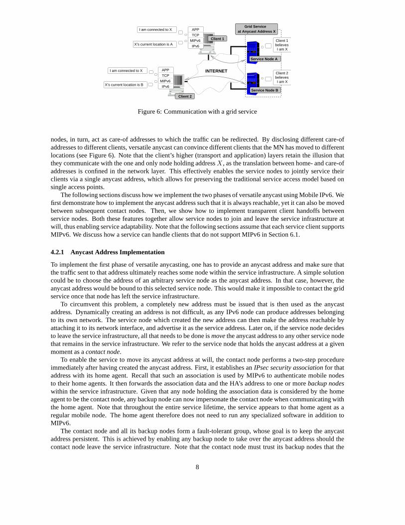
Figure 6: Communication with a grid service
nodes, in turn, act as care-of addresses to which the traffic can be redirected. By disclosing different care-ofaddresses to different clients, versatile anycast can convince different clients that the MN has moved to differentlocations (see Figure 6). Note that the client’s higher (transport and application) layers retain the illusion thatthey communicate with the one and only node holding addressX , as the translation between home- and care-ofaddresses is confined in the network layer. This effectivelyenables the service nodes to jointly service theirclients via a single anycast address, which allows for preserving the traditional service access model based onsingle access points.
The following sections discuss how we implement the two phases of versatile anycast using Mobile IPv6. Wefirst demonstrate how to implement the anycast address such that it is always reachable, yet it can also be movedbetween subsequent contact nodes. Then, we show how to implement transparent client handoffs betweenservice nodes. Both these features together allow service nodes to join and leave the service infrastructure atwill, thus enabling service adaptability. Note that the following sections assume that each service client supportsMIPv6. We discuss how a service can handle clients that do notsupport MIPv6 in Section 6.1.
4.2.1 Anycast Address Implementation
To implement the first phase of versatile anycasting, one hasto provide an anycast address and make sure thatthe traffic sent to that address ultimately reaches some nodewithin the service infrastructure. A simple solutioncould be to choose the address of an arbitrary service node asthe anycast address. In that case, however, theanycast address would be bound to this selected service node. This would make it impossible to contact the gridservice once that node has left the service infrastructure.
To circumvent this problem, a completely new address must beissued that is then used as the anycastaddress. Dynamically creating an address is not difficult, as any IPv6 node can produce addresses belongingto its own network. The service node which created the new address can then make the address reachable byattaching it to its network interface, and advertise it as the service address. Later on, if the service node decidesto leave the service infrastructure, all that needs to be done ismove the anycast address to any other service nodethat remains in the service infrastructure. We refer to the service node that holds the anycast address at a givenmoment as acontact node.
To enable the service to move its anycast address at will, thecontact node performs a two-step procedureimmediately after having created the anycast address. First, it establishes anIPsec security association for thataddress with its home agent. Recall that such an associationis used by MIPv6 to authenticate mobile nodesto their home agents. It then forwards the association data and the HA’s address to one or morebackup nodeswithin the service infrastructure. Given that any node holding the association data is considered by the homeagent to be the contact node, any backup node can now impersonate the contact node when communicating withthe home agent. Note that throughout the entire service lifetime, the service appears to that home agent as aregular mobile node. The home agent therefore does not need to run any specialized software in addition toMIPv6.
The contact node and all its backup nodes form a fault-tolerant group, whose goal is to keep the anycastaddress persistent. This is achieved by enabling any backupnode to take over the anycast address should thecontact node leave the service infrastructure. Note that the contact node must trust its backup nodes that the
8
INTERNET
���������������������������������������������
���������������������������������������������
������������������������
������������������������
���������������
���������������
���������������������������������������������
���������������������������������������������
������������������������
������������������������
���������������
���������������
����������������������
����������������������
����������������������
����������������������
����������������������
����������������������
����������������������
����������������������
IPsec Data
IPsec Data
IPsec Data
Backup Node
Home Agent
Contact Node(already gone)Tunnel all traffic to me.
I am mobile node X.
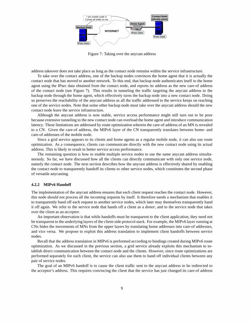
Figure 7: Taking over the anycast address
address takeover does not take place as long as the contact node remains within the service infrastructure.To take over the contact address, one of the backup nodes convinces the home agent that it is actually the
contact node that has moved to another network. To this end, that backup node authenticates itself to the homeagent using the IPsec data obtained from the contact node, and reports its address as the new care-of addressof the contact node (see Figure 7). This results in tunnelingthe traffic targeting the anycast address to thebackup node through the home agent, which effectively turnsthe backup node into a new contact node. Doingso preserves the reachability of the anycast address as all the traffic addressed to the service keeps on reachingone of the service nodes. Note that some other backup node must take over the anycast address should the newcontact node leave the service infrastructure.
Although the anycast address is now stable, service access performance might still turn out to be poorbecause extensive tunneling to the new contact node can overload the home agent and introduce communicationlatency. These limitations are addressed by route optimization wherein the care-of address of an MN is revealedto a CN. Given the care-of address, the MIPv6 layer of the CN transparently translates between home- andcare-of addresses of the mobile node.
Since a grid service appears to its clients and home agents asa regular mobile node, it can also use routeoptimization. As a consequence, clients can communicate directly with the new contact node using its actualaddress. This is likely to result in better service access performance.
The remaining question is how to enable multiple service nodes to use the same anycast address simulta-neously. So far, we have discussed how all the clients can directly communicate with only one service node,namely the contact node. The next section describes how the anycast address is effectively shared by enablingthe contact node to transparently handoff its clients to other service nodes, which constitutes the second phaseof versatile anycasting.
4.2.2 MIPv6 Handoff
The implementation of the anycast address ensures that eachclient request reaches the contact node. However,this node should not process all the incoming requests by itself. It therefore needs a mechanism that enables itto transparently hand off each request to another service nodes, which later may themselves transparently handit off again. We refer to the service node that hands off a client as adonor, and to the service node that takesover the client as anacceptor.
An important observation is that while handoffs must be transparent to the client application, they need notbe transparent to the underlying layers of the client-side protocol stack. For example, the MIPv6 layer running atCNs hides the movements of MNs from the upper layers by translating home addresses into care-of addresses,and vice versa. We propose to exploit this address translation to implement client handoffs between servicenodes.
Recall that the address translation in MIPv6 is performed according to bindings created during MIPv6 routeoptimization. As we discussed in the previous section, a grid service already exploits this mechanism to es-tablish direct communication between the contact node and the clients. However, since route optimizations areperformed separately for each client, the service can also use them to hand off individual clients between anypair of service nodes.
The goal of an MIPv6 handoff is to cause the client traffic sentto the anycast address to be redirected tothe acceptor’s address. This requires convincing the client that the service has just changed its care-of address
9
INTERNET
����������������������������������������
����������������������������������������
������������������������
������������������������
���������������
���������������
����������������������������������������
����������������������������������������
������������������������
������������������������
���������������
���������������
����������������������������������������
����������������������������������������
������������������������
������������������������
���������������
���������������
���������������������
���������������������
���������������������
���������������������
���������������������
���������������������
���������������������
���������������������
���������������������
���������������������
���������������������
���������������������
Client
Home Agent
Contact Node
DonorAcceptor
INIT
INTERNET
����������������������������������������
����������������������������������������
������������������������
������������������������
���������������
���������������
����������������������������������������
����������������������������������������
������������������������
������������������������
���������������
���������������
����������������������������������������
����������������������������������������
������������������������
������������������������
���������������
���������������
���������������������
���������������������
���������������������
���������������������
���������������������
���������������������
���������������������
���������������������
���������������������
���������������������
���������������������
���������������������
Acceptor
Client
Home Agent
Contact Node
Donor
HOTICOTI
HOTIHOTI
(a) (b)
INTERNET
���������������������������������������������
���������������������������������������������
������������������������
������������������������
���������������
���������������
���������������������������������������������
���������������������������������������������
������������������������
������������������������
���������������
���������������
���������������������������������������������
���������������������������������������������
������������������������
������������������������
���������������
���������������
�����������������������
�����������������������
�����������������������
�����������������������
�����������������������
�����������������������
�����������������������
�����������������������
�����������������������
�����������������������
�����������������������
�����������������������
Acceptor
Client
Home Agent
Contact Node
Donor
HOT
COT
HOTHOT
INTERNET
���������������������������������������������
���������������������������������������������
������������������������
������������������������
���������������
���������������
���������������������������������������������
���������������������������������������������
������������������������
������������������������
���������������
���������������
���������������������������������������������
���������������������������������������������
������������������������
������������������������
���������������
���������������
�����������������������
�����������������������
�����������������������
�����������������������
�����������������������
�����������������������
�����������������������
�����������������������
�����������������������
�����������������������
�����������������������
�����������������������
Acceptor
Client
Home Agent
Contact Node
Donor
BU
BA
(c) (d)
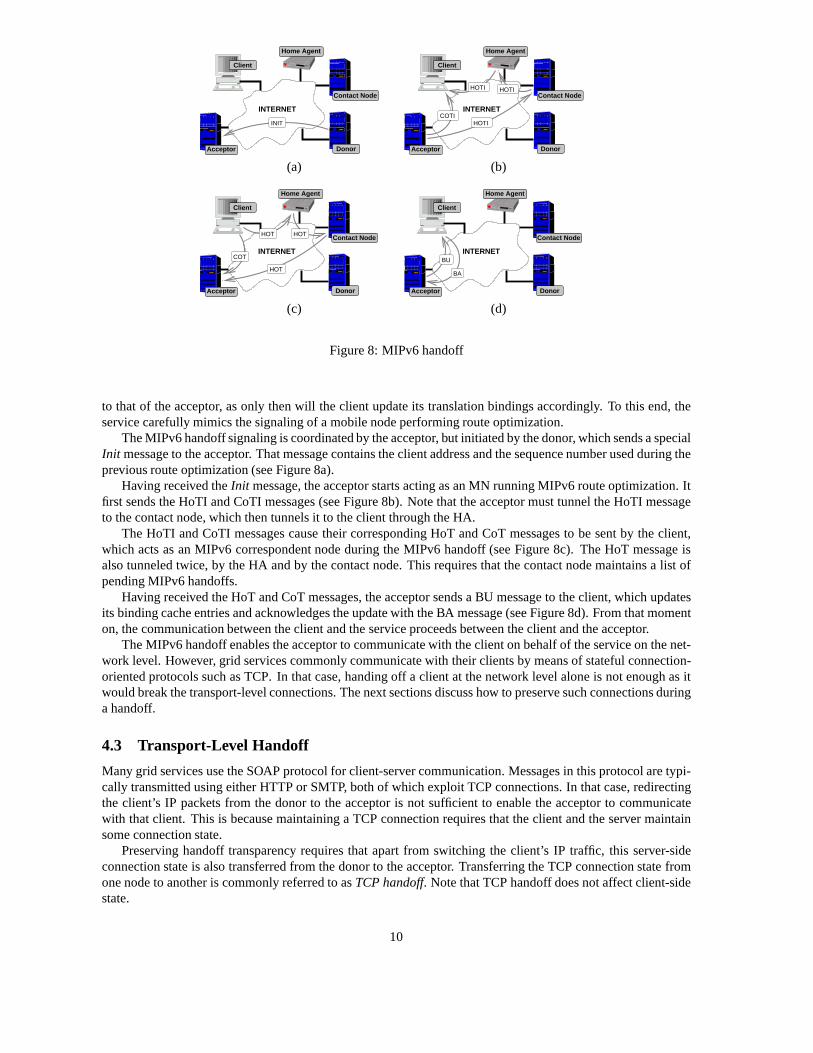
Figure 8: MIPv6 handoff
to that of the acceptor, as only then will the client update its translation bindings accordingly. To this end, theservice carefully mimics the signaling of a mobile node performing route optimization.
The MIPv6 handoff signaling is coordinated by the acceptor,but initiated by the donor, which sends a specialInit message to the acceptor. That message contains the client address and the sequence number used during theprevious route optimization (see Figure 8a).
Having received theInit message, the acceptor starts acting as an MN running MIPv6 route optimization. Itfirst sends the HoTI and CoTI messages (see Figure 8b). Note that the acceptor must tunnel the HoTI messageto the contact node, which then tunnels it to the client through the HA.
The HoTI and CoTI messages cause their corresponding HoT andCoT messages to be sent by the client,which acts as an MIPv6 correspondent node during the MIPv6 handoff (see Figure 8c). The HoT message isalso tunneled twice, by the HA and by the contact node. This requires that the contact node maintains a list ofpending MIPv6 handoffs.
Having received the HoT and CoT messages, the acceptor sendsa BU message to the client, which updatesits binding cache entries and acknowledges the update with the BA message (see Figure 8d). From that momenton, the communication between the client and the service proceeds between the client and the acceptor.
The MIPv6 handoff enables the acceptor to communicate with the client on behalf of the service on the net-work level. However, grid services commonly communicate with their clients by means of stateful connection-oriented protocols such as TCP. In that case, handing off a client at the network level alone is not enough as itwould break the transport-level connections. The next sections discuss how to preserve such connections duringa handoff.
4.3 Transport-Level Handoff
Many grid services use the SOAP protocol for client-server communication. Messages in this protocol are typi-cally transmitted using either HTTP or SMTP, both of which exploit TCP connections. In that case, redirectingthe client’s IP packets from the donor to the acceptor is not sufficient to enable the acceptor to communicatewith that client. This is because maintaining a TCP connection requires that the client and the server maintainsome connection state.
Preserving handoff transparency requires that apart from switching the client’s IP traffic, this server-sideconnection state is also transferred from the donor to the acceptor. Transferring the TCP connection state fromone node to another is commonly referred to asTCP handoff. Note that TCP handoff does not affect client-sidestate.
10

TCP TCP
AcceptorDonor
Socket StateSERVER
CODESERVER
CODE
KERNELKERNEL
Figure 9: Socket migration
Performing a TCP handoff together with an MIPv6 handoff results in transparent switching of the completeTCP connection from the donor to the acceptor. As a result, the client and the acceptor communicate directlywith each other, which eliminates the need for shared front ends often employed by clusters. This makes TCPhandoffs implemented by anadaptable grid service fundamentally different from those implemented by theircluster-based counterparts.
This section describes how TCP handoffs are supported in an adaptable grid service. We first describe somebasic properties of the TCP protocol, and then propose a procedure to hand off TCP connections on top ofMIPv6 handoff.
4.3.1 TCP Properties
TCP is a reliable communication protocol based on IP. Reliability of communication is ensured by means ofacknowledgments and retransmissions. In TCP, each transmitted packet is numbered and must be acknowledgedby the receiver. Should that not happen within some period oftime, then the packet is assumed to be lost andtherefore periodically retransmitted until its acknowledgment arrives, or a timeout occurs.
TCP requires the communicating parties to maintain some state. This state mainly consists of identifiersused for recent acknowledgments and (re)transmissions, along with buffers containing the data that have not yetbeen sent or acknowledged. The total size of a TCP connectionstate depends on the buffer sizes, and variesfrom 90 bytes to around 90 kB.
The control states maintained by both ends of a TCP connection must remain consistent for the protocol tofunction properly. If one party receives a message proving that the other end is not in a legal control state, thenit resets the connection.
Each end of a TCP connection is attached to a TCP socket. Sockets are an abstraction of various communi-cation mechanisms provided by the operating system. Clientapplications and service implementations use TCPsockets to send and receive data over TCP connections. Operating systems, in turn, use TCP sockets to store thestate of these connections.
4.3.2 TCP Handoff
Transferring the state of a TCP connection effectively means that the server-side TCP socket is migrated fromthe donor to the acceptor. To this end, the donor must extractthe socket state from the operating system’s kerneland send it to the acceptor. The acceptor, in turn, re-creates the socket in its own kernel based on the receivedstate (see Figure 9).
We support TCP socket migration by means of the open-source TCPCP package [23]. It consists of a user-level library and a patch for the Linux kernel. TCPCP enablesany donor application to extract an open TCPsocket from the kernel in a serialized form. Given that serialized form, TCPCP re-creates the TCP socket in theacceptor application, possibly running on another node. The IP-level traffic associated with the TCP socket isassumed to be switched by some other mechanism.
The problem here is that while the socket is being migrated, the client may send data or acknowledgmentsto the server. We must therefore ensure that packets issued by the client during the migration can never reacha node that does not hold the corresponding TCP socket. Otherwise, the receiving member node would issueTCP control messages back reporting a missing socket, whichwould cause the connection to be reset. TCPCPsolves this problem by maintaining two separate instances of the server-side socket during the period when itis unclear whether client-issued packets will reach the donor or the acceptor. In this way, the client traffic sentduring the handoff always reaches some socket instance and can never trigger the connection reset.
11

INTERNET
���������������������������������������������
���������������������������������������������
������������������������
������������������������
���������������
���������������
���������������������������������������������
���������������������������������������������
������������������������
������������������������
���������������
���������������
����������������������
����������������������
����������������������
����������������������
����������������������
����������������������
����������������������
����������������������
TCP
Acceptor
Client
Donor
TCP Connection
Frozen TCP socketto handoff
INIT
INTERNET
���������������������������������������������
���������������������������������������������
������������������������
������������������������
���������������
���������������
���������������������������������������������
���������������������������������������������
������������������������
������������������������
���������������
���������������
����������������������
����������������������
����������������������
����������������������
����������������������
����������������������
����������������������
����������������������
TCP
TCP
Client
Acceptor
Donor
Frozen TCP sockets
Starting MIPv6 Handoff
INTERNET
���������������������������������������������
���������������������������������������������
������������������������
������������������������
���������������
���������������
���������������������������������������������
���������������������������������������������
������������������������
������������������������
���������������
���������������
����������������������
����������������������
����������������������
����������������������
����������������������
����������������������
����������������������
����������������������
TCP
Client
Acceptor
Donor
Frozen TCP socketto remove
DONE
(a) (b) (c)
Figure 10: TCP handoff
Maintaining two server-side socket instances forces TCPCPto keep their states consistent with each other,and with the connection state held by the client. TCPCP achieves that by simply disallowing the TCP connectionstate to change during the migration. To this end, it freezesthe socket right before extracting it from thekernel. A frozen socket does not send any data nor acknowledgments, and it silently drops all the incomingdata or acknowledgments without processing them. Note thatthe dropped data and acknowledgments will beretransmitted by the client. The socket is unfrozen after the IP-level traffic has been switched.
The TCP handoff procedure is depicted in Figure 10. The donorfirst freezes and extracts the TCP socketfrom the kernel. The socket is then sent in theInit message (also used for MIPv6 handoff in Figure 8) to theacceptor, which re-creates the socket in its own kernel (Figure 10a). Having re-created the socket, the acceptorconveys the MIPv6 handoff to switch the client traffic from the donor to the acceptor (Figure 10b). Note that thetwo server-side socket instances are kept frozen during theMIPv6 handoff. Once the MIPv6 handoff has beencompleted, the acceptor unfreezes its socket, which can immediately be used to communicate with the client.The acceptor also notifies the donor about the handoff completion with aDone message, so that the donor cansafely remove its frozen socket instance (Figure 10c).
Combining the TCP and MIPv6 handoffs allows a grid service tomigrate server-side TCP sockets amongnodes within its infrastructure without breaking the associated TCP connections. To maintain the handoff trans-parency, however, the service must also ensure that the datasent over this connection by the acceptor are con-sistent at the application level with those sent by the donorbefore the handoff. We discuss this issue next.
4.4 Application-Level Handoff
Migrating the server-side TCP socket enables the acceptor to send service data to the client over the same TCPconnection that was used by the donor before the migration. As a consequence, each socket migration logicallydivides the service response data sent to the client into twoparts, depending on which service node actually sentthe data.
Preserving the handoff transparency requires that this logical division remains invisible to the client, whichexpects all the response data to be sent by a single service node. The part sent after the handoff must thereforeseamlessly match the part sent before the handoff, and all the parts together must form a response that is validin terms of the service protocol.
Generating subsequent response parts without violating the service protocol requires that the donor passesthe application-level state of the connection to the acceptor. Given that state, the acceptor generates and sendsits response part as if it had generated all the previous response parts as well.
Passing the application-level state requires it to be serialized. The serialization method is typically application-specific. In HTTP, for example, a response is generated afterreceiving an HTTP request, and consists of a headerand the actual requested content. In that case, the serialized application-level state consists of the HTTP requestbeing serviced, an indicator saying whether the HTTP headerhas already been sent, and the description of thecontent part that has been sent so far. If the content is a static document, then such a description can simply bethe document name and the offset at which the previous content part ends.
The donor sends the serialized application-level state to the acceptor together with theInit message depictedin Figures 8 and 10. Recall that this message also contains all the data necessary to perform handoffs at the
12

transport and network layers. Constructing such a message therefore requires that the donor concatenates thesequence number from the local MIPv6 implementation, the TCP socket state, and the application-level state.
To relieve the service implementation from dealing with handoffs at different levels, the construction ofInitmessages can be implemented in a separate library. We discuss the syntax of the library calls in C, but the libraryitself can also be implemented in Java or in any other language. The core function of that library is:
client handoff(client socket fd, acceptor IP, app state)
which constructs theInit message, sends it to the acceptor, and waits for theDone message that signals the hand-off completion. The donor would call this function to migrate a given client socket along with the application-level state to the acceptor. Once the call returns, the donorcloses the client socket using the standardclose()call.
All that is needed at the acceptor’s side is to create a special socket bound to a well-known port, which isused to receiveInit messages from donors. Whenever a message arrives at this socket, the acceptor can callanother library function to accept an incoming handoff:
client receive(special socket fd, &client socket fd, &app state)
This function reads theInit message from the special socket, performs the MIPv6 and TCP handoff, and sendstheDone message to the donor once these handoffs are complete. Finally, the functionreturns the client socketre-created by the TCP handoff and the application-level state. The service instance running on the acceptorsimply needs to unserialize the received application-level state and determine what data should be sent to theclient next. Once this is done, these data are transmitted over the re-created client socket just as over any otherclient socket created using traditional methods. However,the re-created socket must be closed using a speciallibrary functionclient close(client socket fd), which ensures that the MIPv6 binding cache entryon the client side is deleted.
4.5 Summary
Versatile anycast provides grid services with logical addresses, and enables each such service to redirect clienttraffic from its logical addresses to the physical addressesof the service nodes for load balancing. The servicenodes can also handoff individual each client among themselves, which enables service nodes to join and leavethe service infrastructure as necessary. The resulting decoupling between the logical service address and theservice infrastructure contributes to the improved service adaptability and comes at the expense of upgradingthe service nodes such that they support versatile anycast functions.
However, as versatile anycast is just a routing mechanism, it cannot make a grid service adaptable by itself.To this end, the service needs to implement a number of additional functions such as membership managementand load balancing. These functions enable the service to react to the changes in the composition of its in-frastructure, and to select service nodes to which clients should be redirected or handed off. Both membershipmanagement and load balancing can be implemented using standard techniques [24, 25].
5 Evaluation
We evaluate the performance of versatile anycast using a simple testbed (see Figure 11). The core of that testbedis a NISTnet router, which connects the client machine to a service infrastructure [26]. The infrastructureconsists of two service nodes located in different networks, which are connected to the NISTnet core via theirhome agents.
We use the NISTnet router to emulate wide-area latencies. However, since NISTnet is not IPv6-enabled, weestablished three IP6-in-IP4 tunnels:SS to control packet transmission between the member nodes, and CS1 andCS2 to control packet transmission between these member nodes and the client.
The NISTnet router runs Linux 2.4.20. All the remaining machines run Linux 2.6.8.1 and MIPL-2.0-RC1,which is an open-source MIPv6 implementation for Linux [27]. All the machines are equipped with PIII pro-cessors, with clocks varying from 450 to 700 MHz.
13

���������������������������������������������
���������������������������������������������
������������������������
������������������������
���������������
���������������
���������������������������������������������
���������������������������������������������
������������������������
������������������������
���������������
���������������
�����������������������
�����������������������
�����������������������
�����������������������
�����������������������
�����������������������
�����������������������
�����������������������
IPv6 LANs
Node 1
Node 2
Home Agent 1
Home Agent 2
SSCS1
CS2
Client
RouterNISTnet
Figure 11: Testbed topology
5.1 Server Access Latency
The anycast address implementation based on tunneling provided by MIPv6 causes the client packets to berouted through the home agent, which then tunnels them to thecontact node. The service access latency thereforeconsists of two parts: the latency between the client and thehome agent, and the latency between the home agentand the contact node.
To verify this claim, we developed a simple UDP-echo application. A UDP-echo client sends a 128-byteUDP packet to the service, which sends that packet back. The client measures the round-trip time as the delaybetween sending and receiving the packet.
We used two different configurations of the UDP-echo service. Both configurations use the anycast addressescreated by Node 1. However, whereas Node 1 belongs to the service in the first configuration, it does not in thesecond one. In that case, the packets are tunneled between Home Agent 1 and Node 2.
For each service configuration, we have configured NISTnet with several combinations of latency values.Packets transmitted through the SS tunnel were delayed by various latenciesLatSS . Packets transmitted throughthe CS1 tunnel, in turn, were delayed by various latenciesLatCS1. For each pair of latencies, we iteratively ranthe UDP-echo client 100 times and calculated the average over the reported round-trip times.
The results were very consistent. The average reported round-trip time was2∗LatCS1+X for configuration1, and2 ∗LatCS1 + 2 ∗LatSS + Y for configuration 2, where X and Y are small additional delays(on average2.13 ms and 3.61 ms, respectively). We attribute the X and Y delays to the latency of Ethernet links and the timeof local processing at all the machines visited by the UDP packets.
Recall that the grid service can use route optimization to enable direct communication between its clientsand the contact node. However, since route optimization takes place in parallel to the application-level com-munication, we do not consider it in this experiment, and analyze it only when evaluating the handoff timesbelow.
5.2 Handoff Time Decomposition
Versatile anycast enables the service nodes to hand off a client TCP connection among each other. In thisexperiment, we investigate how much time is necessary to hand off a TCP connection, and what operationsconsume most of that time.
Handoffs are performed by a simple service that delivers 1 MBof content upon request. The client firstopens a TCP connection to Node 1 acting as the contact node. Node 1 transfers 500 kB of data, and hands offthe connection to Node 2 immediately after the lastsend() call returns. Node 2 sends another 500 kB of dataand closes the connection.
The total handoff time can be divided into seven phases (see Table 1). The phases are delimited by the eventof sending or receiving some specific packets, which we time-stamp to mark the boundary between subsequentphases. To detect events, we monitor all the packets exchanged in the testbed usingtcpdump listening on all thenetwork interfaces of the NISTnet router.
Table 1 reports the delays averaged over 100 download sessions. We have emulated various speeds of theupstream DSL connections by shaping the traffic sent from thehome agents to the NISTnet router using thestandardcbq queuing discipline available in the Linux kernel. The results for unshaped 100 Mbps Ethernet areincluded for completion.
14

Table 1: Handoff time decomposition (without NISTnet delays)
No. Operation NameInter-node Bandwidth
100 Mbps 2 Mbps 1.5 Mbps 1 Mbps
1 Socket Extraction 0.8 ms 5.8 ms 6.9 ms 11.8 ms2 State Transfer 6.5 ms 319.1 ms 434.1 ms 648.2 ms3 Socket Re-creation 2.2 ms 2.1 ms 2.1 ms 2.2 ms4 Return-Routability Procedure 2.5 ms 3.7 ms 4.9 ms 8.9 ms5 BU-Message Construction 2.7 ms 2.7 ms 2.7 ms 2.7 ms6 Binding-Management Procedure 2.6 ms 2.6 ms 2.6 ms 2.6 ms7 Socket Activation 1.1 ms 1.1 ms 1.1 ms 1.1 ms
Total Time: 18.4 ms 337.1 ms 454.4 ms 677.5 ms
As can be observed, extracting the socket at the donor apparently takes between 0.8 and 11.8 ms dependingon the network bandwidth (Phase 1). However, since this operation is entirely local, it should not depend onthe bandwidth at all. We have therefore verified these results by measuring the actual time spent in the socket-extracting call, which turned out to be 0.8 ms on average. We believe that the higher values obtained usingpacket monitoring result from transmission delays introduced by bandwidth shaping.
Most of the total handoff time is spent on transferring the socket state (Phase 2). The duration of this phaseis proportional to the network bandwidth, as each time the donor transfers the 90 kB of the socket state to theacceptor. This time accounts for up to 95% of the total handoff time when emulating 1 Mbps DSL lines.
Local phases such as re-creating the socket, constructing the BU message, and activating the socket corre-spond turn out to be relatively fast and independent of the bandwidth (Phases 3, 5, and 7). The return-routabilityprocedure, in turn, demonstrated some dependency on the bandwidth (Phase 4). However, since the packetstransmitted during this phase are very small, we believe that this dependency is artificial, and results fromdelaying packets by the shaping mechanism previously observed for Phase 1.
Interestingly, the artificial delays introduced by traffic shaping cannot be observed for the binding manage-ment procedure, where the BU and BA messages are exchanged between the acceptor and the client (Phase 6).This is probably because the low network activity during Phases 3-5 causes the state of the shaping mechanismto be reset by the time Phase 6 starts, which enables the two packets to be transmitted without any delay.
We also performed the same experiment for various combinations ofLSS, LCS1, andLCS2 latencies emu-lated by NISTnet (we usedLCS1 = LCS2). The results are similar to those presented in Table 1, except that thetime spent in some phases varies proportionally to the NISTnet latencies. In particular, phase 2 varies byLSS,phase 4 varies by2 ∗LSS + 2 ∗LCS1, and phase 6 varies by2 ∗LCS2. The additional delays correspond to thelatencies of network paths followed by the messages exchanged during the respective phases. Note that shouldany of the MIPv6 packets be lost, it will be automatically retransmitted; in that case, the overall handoff timewill obviously be extended by the MIPv6 retransmission timeout of 1 second.
5.3 State Transfer Optimization
The previous experiment shows that most of the handoff time is spent transferring the socket state from thedonor to the acceptor. The reason why that transfer takes so long is that in this experiment the donor extracts thesocket immediately after the lastsend() call returns. This means that the socket buffers are nearly full, whichresults in the socket size taking about 90 kB.
One way of reducing this size is to simply wait for some time asthe donor gradually sends the data storedin the socket buffers and removes the data acknowledged by the client from the buffers. This would allow theclient to receive and acknowledge at least some of the data, which in turn would reduce the socket state. In thisexperiment, we investigate how such waiting affects the handoff time.
We modified our server so that it would wait for a given period of time between passing the last data to thesocket and starting the actual handoff procedure. We also modified the client such that it measures its perceivedhandoff time. We define the client-perceived handoff time asthe delay between receiving the last packet fromthe donor and the first packet from the acceptor.
15

Clie
nt−
perc
eive
dH
ando
ff T
ime
(ms)
0 200 400 600 800 1000
Lcs=0 Lss=0Lcs=20 Lss=10
Lcs=40 Lss=20
900 800 700 600 500 400 300
100 200
1000
0
Donor Waiting Time (ms)
1000 900 800 700 600 500 400 300 200 100
0 0
Lcs=20 Lss=10Lcs=0 Lss=0
Lcs=40 Lss=20
Han
doff
time
(ms)
Clie
nt−
perc
eive
d
200 400 600 800 1000Donor Waiting Time (ms)
0
200
400
600
800
1000
1200
0 200 400 600 800 1000
Lsc=40 Lss=20
Lsc=0 Lss=0Lsc=20 Lss=10
Han
doff
Tim
e (m
s)C
lient
−pe
rcei
ved
Donor Waiting Time (ms)
(a) 1 Mbps (b) 1.5 Mbps (c) 2 Mbps
Figure 12: Client-perceived handoff times for various upstream node connection bandwidths
Client
ACK BA
BU DATA
3 4 5 6 7
HoTCoT
HoTICoTI
1
2
INIT
AcceptorDonor
Client
ACK
3 4 51
2
INIT
AcceptorDonor
BU
BA
DATA
(a) (b)
Figure 13: Optimizing wide-area latencies
Given the modified application, we repeatedly ran 100 download sessions for 1 MB of content and waitingtimes varying from 0 to 1000 ms with a step of 25 ms. Similar to the previous experiments, we emulatedthree different DSL connection bandwidths and various combinations of wide-area latencies. The results arepresented in Figure 12.
Increasing the donor’s waiting time causes the client-perceived handoff time to decrease to some minimumvalue. Having reached that value, the client-perceived handoff time starts increasing. We verified that theminimum value corresponds to the situation when the socket was extracted right after receiving the last ac-knowledgment from the client, which removes the last packetfrom the socket buffers. As a consequence, thesocket state has only 90 bytes, which can be transferred in the time of the one-way latency between the donorand the acceptor. This eliminates the delay resulting from transferring a large socket state over a low-bandwidthconnection. We conclude that the donor should always empty its output TCP buffers before freezing the socketand starting the handoff.
5.4 Handoff Time Optimization
Now that the socket state is reduced to sending a single packet from the donor to the acceptor, and given thatthe local processing times are negligible, the actual handoff time depends only on the latencies of the pathsfollowed by the messages exchanged during the handoff. In this experiment, we investigate whether this timecan be reduced even further.
Recall that the client-perceived handoff time is the delay between receiving the last packet from the donorand the first packet from the acceptor. The beginning of the client-perceived handoff time corresponds to sendingthe last acknowledgment to the donor (message 1 in Figure 13(a)). Upon receiving that acknowledgment, thedonor sends theInit message to the acceptor, which then runs the complete MIPv6 handoff. Once the MIPv6handoff is complete, the acceptor sends the first packet containing the application data to the client. The client-perceived handoff time ends once that packet is received by the client.
In fact, all these steps do not need to be performed sequentially. In particular, the acceptor can run the return-routability procedure in advance while the donor is still busy with transferring data to the client, as no data otherthan the client address is needed for that. Performing the return-routability procedure in advance eliminates itstime from the client-perceived handoff time, and allows thedonor to send the BU message immediately aftertheInit message arrives (see Figure 13(b)).
16

10 20 30 40 50 60 70 0
100
200
300
400
500
600
Clie
nt−
Per
ceiv
edH
ando
ff T
ime
(ms)
One−way Client Latency (Lsc) (ms)
Full Handoff
Optimized Handoff
80One−way Server Latency (Lss) (ms)
600
500
400
300
200
100
0 10 20
Optimized Handoff
Full Handoff
Han
doff
Tim
e (m
s)C
lient
−pe
rcei
ved
80 70 60 50 40 30
(a) (b)
Figure 14: The impact of performing return-routability procedures in advance
To allow the acceptor to run the return-routability procedure in advance, the donor must notify the acceptorabout the upcoming handoff by sending aPrepare message containing the client address. This message is sentwhen the donor has passed all its data to the socket and is about to start waiting for the last acknowledgmentfrom the client. Having received thePrepare message, the acceptor conveys the return-routability procedureand keeps the resulting Kbm so that it can be sent in the BU message once theInit message arrives.
To investigate the impact of performing the return-routability procedure in advance, we modified our testapplication once again. In the new version, the donor sends thePrepare message immediately after returningfrom the lastsend() call, and then waits for the socket to become empty. The acceptor performs the return-routability procedure upon receiving thePrepare message, and waits for theInit message before sending the BUmessage to the client.
Similar to the previous experiment, we measured the averageclient-observed handoff times for 100 down-load sessions with the network bandwidth shaped to 2 Mbps andvarious combinations ofLCS andLSS laten-cies. Figure 14(a) shows the results obtained forLSS fixed to 20 ms andLCS varying from 10 to 80 ms, whereasFigure 14(b) shows the results obtained forLCS fixed to 40 ms andLSS varying from 10 to 80 ms.
As can be observed, performing return-routability procedures in advance results in the reduction of client-observed handoff times. The reduction is proportional bothto the latency between the client and the serverand to the latency between the member nodes. This is because our optimization effectively reduces the client-observed handoff time from approximately6 ∗LCS + 3 ∗ LSS to approximately4 ∗ LCS + LSS since the timeof tunneling the HoT/HoTI messages between the acceptor andthe contact node is aboutLSS. Note that thegain is lower if the donor’s waiting time is too short to allowthe acceptor to complete the return-routabilityprocedure before theInit message is sent. This can sometimes be observed for largeLSS values, which resultsin an increased slope in Figure 14(b) forLSS equal or greater than 60 ms.
6 Discussion
6.1 Client-side MIPv6 Support
Our proposed mechanisms assume that client-side operatingsystems support the functionality of an MIPv6correspondent node. This is already true for many popular operating systems, including Linux and Win-dows [27, 28]. Besides, we expect that grid machines runningclient applications can be configured to implementMIPv6 [29]. However, it might still happen that some potential service clients do not support MIPv6.
A grid service running versatile anycast can support a smallnumber of MIPv6-disabled clients. Recallthat the client-side MIPv6 support is necessary to hand off clients among member nodes using route optimiza-tion, but it is not required to access the contact node. MIPv6-disabled clients can therefore be supported bytunneling all their traffic through the contact node. However, the number of MIPv6-disabled clients that areserviced simultaneously by the contact node should not be too large to prevent the contact node from becominga bottleneck.
17
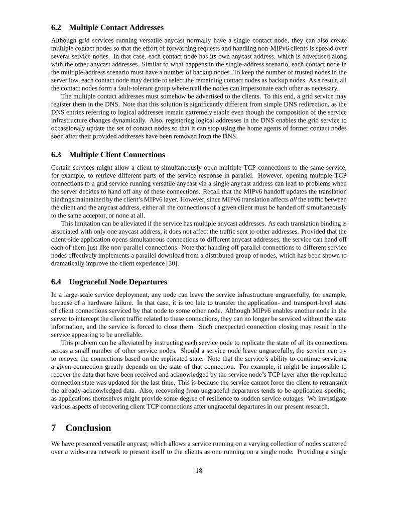
6.2 Multiple Contact Addresses
Although grid services running versatile anycast normallyhave a single contact node, they can also createmultiple contact nodes so that the effort of forwarding requests and handling non-MIPv6 clients is spread overseveral service nodes. In that case, each contact node has its own anycast address, which is advertised alongwith the other anycast addresses. Similar to what happens inthe single-address scenario, each contact node inthe multiple-address scenario must have a number of backup nodes. To keep the number of trusted nodes in theserver low, each contact node may decide to select the remaining contact nodes as backup nodes. As a result, allthe contact nodes form a fault-tolerant group wherein all the nodes can impersonate each other as necessary.
The multiple contact addresses must somehow be advertised to the clients. To this end, a grid service mayregister them in the DNS. Note that this solution is significantly different from simple DNS redirection, as theDNS entries referring to logical addresses remain extremely stable even though the composition of the serviceinfrastructure changes dynamically. Also, registering logical addresses in the DNS enables the grid service tooccassionaly update the set of contact nodes so that it can stop using the home agents of former contact nodessoon after their provided addresses have been removed from the DNS.
6.3 Multiple Client Connections
Certain services might allow a client to simultaneously open multiple TCP connections to the same service,for example, to retrieve different parts of the service response in parallel. However, opening multiple TCPconnections to a grid service running versatile anycast viaa single anycast address can lead to problems whenthe server decides to hand off any of these connections. Recall that the MIPv6 handoff updates the translationbindings maintained by the client’s MIPv6 layer. However, since MIPv6 translation affectsall the traffic betweenthe client and the anycast address, either all the connections of a given client must be handed off simultaneouslyto the same acceptor, or none at all.
This limitation can be alleviated if the service has multiple anycast addresses. As each translation binding isassociated with only one anycast address, it does not affectthe traffic sent to other addresses. Provided that theclient-side application opens simultaneous connections to different anycast addresses, the service can hand offeach of them just like non-parallel connections. Note that handing off parallel connections to different servicenodes effectively implements a parallel download from a distributed group of nodes, which has been shown todramatically improve the client experience [30].
6.4 Ungraceful Node Departures
In a large-scale service deployment, any node can leave the service infrastructure ungracefully, for example,because of a hardware failure. In that case, it is too late to transfer the application- and transport-level stateof client connections serviced by that node to some other node. Although MIPv6 enables another node in theserver to intercept the client traffic related to these connections, they can no longer be serviced without the stateinformation, and the service is forced to close them. Such unexpected connection closing may result in theservice appearing to be unreliable.
This problem can be alleviated by instructing each service node to replicate the state of all its connectionsacross a small number of other service nodes. Should a service node leave ungracefully, the service can tryto recover the connections based on the replicated state. Note that the service’s ability to continue servicinga given connection greatly depends on the state of that connection. For example, it might be impossible torecover the data that have been received and acknowledged bythe service node’s TCP layer after the replicatedconnection state was updated for the last time. This is because the service cannot force the client to retransmitthe already-acknowledged data. Also, recovering from ungraceful departures tends to be application-specific,as applications themselves might provide some degree of resilience to sudden service outages. We investigatevarious aspects of recovering client TCP connections afterungraceful departures in our present research.
7 Conclusion
We have presented versatile anycast, which allows a servicerunning on a varying collection of nodes scatteredover a wide-area network to present itself to the clients as one running on a single node. Providing a single
18
logical address enables the client-side software to preserve the traditional service access model based on singleaccess points. At the same time, the dynamic composition of anycast groups implemented by versatile anycastenables the service infrastructure to evolve and adapt to changing network conditions.
We propose to implement logical addresses using versatile anycast, which presents a grid service to itsclients as a mobile node. This enables the service to decouple its logical address from the addresses of the nodesforming the service infrastructure. Such a decoupling allows the service to dynamically map its logical addressto any service node while preserving the service reachability. Changing the mapping on a per-client basis, inturn, enables the service to transparently hand off clientsamong the service nodes at the network level whilepreserving optimal routing between the clients and the service nodes.
We have demonstrated that the overhead of contacting a service via its anycast address can be estimatedas the latency between the contact node and the home agent responsible for the contact address. The client-perceived handoff time has also been shown to be a linear function of the latencies among the client and theservice nodes participating in the handoff.
As a routing mechanism, versatile cannot make grid servicesfully adaptable by itself. To this end, a gridservice must combine versatile anycast with some techniques for membership management and load balancing.These techniques enable the service to decide when to use each of the functions provided by versatile anycast.
We believe that decoupling the development of the client-side software from the evolution of the server-sideservice infrastructure is crucial for the successful deployment of large-scale grid services. Our implementationof logical addresses will enable a great variety of servicesto evolve and adapt to the increasing client demandwithout requiring any modifications to the client-side software.
References[1] I. Foster, C. Kesselman, and S. Tuecke, “The Anatomy of the Grid, Enabling Scalable Virtual Organizations,”Inter-
national Journal on High Performance Computing Applications, vol. 15, no. 3, pp. 200–222, 2001.
[2] I. Foster, C. Kesselman, J. Nick, and S. Tuecke, “The Physiology of the Grid: An Open Grid Services Architecture forDistributed Systems Integration,” inOpen Grid Service Infrastructure WG, Global Grid Forum, June 2002.
[3] S. Sivasubramanian, M. Szymaniak, G. Pierre, and M. van Steen, “Replication for Web Hosting Systems,”ACMComputing Surveys, vol. 36, no. 3, pp. 291–334, 2004.
[4] “BitTorrent, Inc.,” http://www.bittorrent.com/.
[5] C. Partridge, T. Medez, and W. Milliken, “Host Anycasting Service,” RFC 1546, Nov. 1993.
[6] M. Szymaniak, G. Pierre, and M. van Steen, “Versatile Anycasting with Mobile IPv6,” inSubmitted for publication,May 2006.
[7] L. A. Barroso, J. Dean, and U. Holzle, “Web Search for a Planet: The Google Cluster Architecture,”IEEE Micro, vol.23, no. 2, pp. 22–28, 2003.
[8] M. Rabinovich and A. Aggarwal, “RaDaR: A Scalable Architecture for a Global Web Hosting Service,”ComputerNetworks, vol. 31, no. 11–16, pp. 1545–1561, 1999.
[9] V. Cardellini, M. Colajanni, and P. S. Yu, “Request Redirection Algorithms for Distributed Web Systems,”IEEETransactions on Parallel and Distributed Systems, vol. 14, no. 4, pp. 355–368, Apr. 2003.
[10] I. Foster and A. Iamnitchi, “On Death, Taxes, and the Convergence of Peer-to-Peer and Grid Computing,” in2ndInternational Workshop on Peer-to-Peer Systems, Feb. 2003.
[11] S. Tuecke, K. Czajkowski, I. Foster, J. Frey, S. Graham,C. Kesselman, T. Maguire, T. Sandholm, P. Vanderbilt, andD. Snelling, “Open Grid Services Infrastructure (OGSI) Version 1.0,” Global Grid Forum Draft Recommendation, July2003.
[12] A. Ganguly, A. Agrawal, P. Boykin, and R. Figueiredo, “WOW: Self-organizing Wide Area Overlay Networks ofVirtual Workstations,” inInternational Symposium on High Performance Distributed Computing, June 2006.
[13] B. Chun, P. Wu, H. Weatherspoon, and J. Kubiatowicz, “ChunkCast: An Anycast Service for Large Content Distribu-tion,” in 5th International Workshop on Peer-to-Peer Systems, Feb. 2006.
[14] M. Castro, P. Druschel, A. Kermarrec, and A. Rowstron, “Scalable Application-Level Anycast for Highly DynamicGroups,” inInternational Workshop on Networked Group Communication, Sept. 2003.
[15] V. Cardellini, E. Casalicchio, M. Colajanni, and P.S. Yu, “The State of the Art in Locally Distributed Web-ServerSystems,”ACM Computing Surveys, vol. 34, no. 2, pp. 263–311, June 2002.
19

[16] E. Brewer, “Lessons from Giant-Scale Services,”IEEE Internet Computing, vol. 5, no. 4, pp. 46–55, 2001.
[17] T. Brisco, “DNS Support for Load Balancing,” RFC1794, Apr. 1995.
[18] J. Dilley, B. Maggs, J. Parikh, H. Prokop, R. Sitaraman,and B. Weihl, “Globally Distributed Content Delivery,”IEEEInternet Computing, vol. 6, no. 5, pp. 50–58, Sept. 2002.
[19] M. J. Freedman, K. Lakshminarayanan, and D. Mazieres, “OASIS: Anycast for Any Service,” in3rd Symposium onNetworked Systems Design and Implementation, May 2006.
[20] D. Johnson, C. Perkins, and J. Arkko, “Mobility Supportin IPv6,” RFC 3775, June 2004.
[21] J. Arkko, V. Devarapalli, and F. Dupont, “Using IPsec toProtect Mobile IPv6 Signaling Between Mobile Nodes andHome Agents,” RFC 3776, June 2004.
[22] D. Harkins and D. Carrel, “The Internet Key Exchange (IKE),” RFC 2409, Nov. 1998.
[23] W. Almesberger, “TCP Connection Passing,” inOttawa Linux Symposium, July 2004.
[24] S. Voulgaris, D. Gavidia, and M. van Steen, “CYCLON: Inexpensive Membership Management for Unstructured P2POverlays,”Journal of Network and Systems Management, vol. 13, no. 2, pp. 197–217, June 2005.
[25] V. Cardellini, M. Colajanni, and P.S. Yu, “RedirectionAlgorithms for Load Sharing in Distributed Web-Server Sys-tems,” in19th International Conference on Distributed Computing Systems, June 1999.
[26] “The NIST Net Network Emulator,”http://www-x.antd.nist.gov/nistnet/.
[27] “MIPL – Mobile IPv6 for Linux,” http://www.mobile-ipv6.org/.
[28] “Mobile IPv6 Systems Research Lab,”http://www.mobileipv6.net/.
[29] F. Cappello, F. Desprez, M. Dayde, E. Jeannot, Y. Jegou,S. Lanteri, N. Melab, R. Namyst, P. Primet, O. Richard,E. Caron, J. Leduc, and G. Mornet, “Grid’5000: A Large Scale,Reconfigurable, Controlable and Monitorable GridPlatform,” in6th International Workshop on Grid Computing, Nov. 2005.
[30] P. Rodriguez, A. Kirpal, and E. Biersack, “Parallel-Access for Mirror Sites in the Internet,” in19th INFOCOMConference, Mar. 2000.
20