Enabling numerical Simulations in semantic 3D City Models using CityGML
27
Enabling numerical Simulations in semantic 3D City Models using CityGML 13th South East Asian Survey Congress, Singapore Arne Schilling Stefan Trometer virtualcitySYSTEMS GmbH CADFEM GmbH Berlin, Germany Grafing, Germany
-
Upload
virtualcitysystems-gmbh -
Category
Technology
-
view
197 -
download
1
Transcript of Enabling numerical Simulations in semantic 3D City Models using CityGML

Enabling numerical Simulations in semantic 3D City Models using CityGML
13th South East Asian Survey Congress, Singapore
Arne Schilling Stefan Trometer
virtualcitySYSTEMS GmbH CADFEM GmbH
Berlin, Germany Grafing, Germany
Arne Schilling, virtualcitySYSTEMS , SEASC 2015 2
Geoportal Solutions
What is Urban Simulation?
Challenge
Project 1 – Urban Air Flow
Project 2 – Urban Blast Simulation
Discussion
Outline

3 Arne Schilling, virtualcitySYSTEMS , SEASC 2015
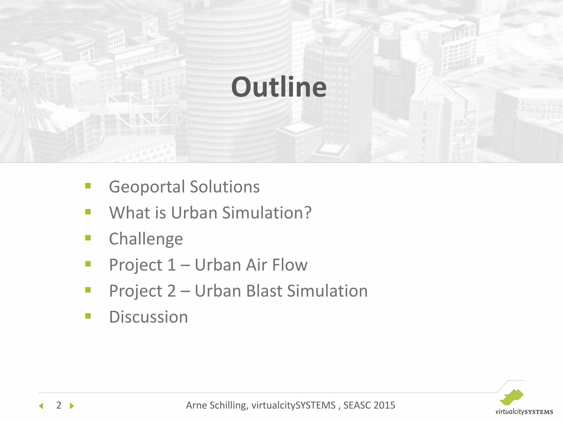
Geoportal Solutions
Points of Interest
4 Arne Schilling, virtualcitySYSTEMS , SEASC 2015
Geoportal Solutions
Integration of OGC Services

5 Arne Schilling, virtualcitySYSTEMS , SEASC 2015
Geoportal Solutions
Spatial & Semantic Queries

6 Arne Schilling, virtualcitySYSTEMS , SEASC 2015
What is Urban Simulation?
Simulation of physical phenomena in urban environments using virtual mockups / 3D city models

7 Arne Schilling, virtualcitySYSTEMS , SEASC 2015
What is Urban Simulation?
Mechanical simulations of building structures
Acoustic studies / blast simulations
Wind field simulations
Simulation of flood events
…

8 Arne Schilling, virtualcitySYSTEMS , SEASC 2015
GIS is not designed for performing complex physical computations
• Strengths of GIS are data management, spatial analysis and visualization
• 3D city models are created using remote sensing and automatic feature extraction methods, not using CAD software
Challenge

9 Arne Schilling, virtualcitySYSTEMS , SEASC 2015
Challenge
GIS is not designed for performing complex physical computations
• Strengths of GIS are data management, spatial analysis and visualization
• 3D city models are created using remote sensing and automatic feature extraction methods, not using CAD software
Physical simulations are frequently done in product design
• Using Computer Aided Design (CAD) and Computer Aided Engineering (CAE) software such as ANSYS
• Based on the Finite Element approach -> Numerical Simulation

10 Arne Schilling, virtualcitySYSTEMS , SEASC 2015
Challenge
GIS is not designed for performing complex physical computations
• Strengths of GIS are data management, spatial analysis and visualization
• 3D city models are created using remote sensing and automatic feature extraction methods, not using CAD software
Physical simulations are frequently done in product design
• Using Computer Aided Design (CAD) and Computer Aided Engineering (CAE) software such as ANSYS
• Based on the Finite Element approach -> Numerical Simulation
Technological gap between GIS and CAE Worlds
• CityGML cannot be loaded by CAE software (e.g. ANSYS). Geometrical representations are very different -> we need conversion tools
• Requirements on data quality are different
• Simulation results are mostly stored in proprietary formats

11 Arne Schilling, virtualcitySYSTEMS , SEASC 2015
Challenge
Create a workflow from 3D Geographic Information Systems to Simulation frameworks and back

12 Arne Schilling, virtualcitySYSTEMS , SEASC 2015
Simulating the wind flow in urban environments for calculating pedestrian comfort levels
Collaboration with IDAC Ltd.
Part of Environmental Impact Assessment
Project 1 - Urban Air Flow
Partners
Pedestrian comfort at ground level (streamlines)
Velocity contours at a height of 7m and 150m
Novosibirsk State University of Architecture and Civil Engineering

13 Arne Schilling, virtualcitySYSTEMS , SEASC 2015
Data set: Frankfurt a.M. Germany: many high rise buildings
Approach: Computational Fluid Dynamics (CFD) analysis
Typical wind loads described by velocity profiles were applied
The Navier-stokes equations were solved along with the 𝑘−𝜀 turbulence model.
The analysis was performed using ANSYS CFX “high-performance, general purpose fluid dynamics program”
Project 1 - Urban Air Flow
13
From http://www.ansys.com

14 Arne Schilling, virtualcitySYSTEMS , SEASC 2015
Data Link - Geometry Processing Format Conversion from CityGML to STEP
Recreation of geometry and topology
Error detection and Geometry healing
• no self intersections
• no non-manifold geometries
• no interior surfaces
• no holes (“watertight”)
• no stray elements
Defeaturing
Project 1 - Urban Air Flow
14
Geometry healing, e.g. removing inner surfaces (top) and resolving self-intersections (bottom)

15 Arne Schilling, virtualcitySYSTEMS , SEASC 2015
Numerical Computations Meshing -> ca. 43 Mio. elements
Setting physical properties (e.g. air density)
Boundary conditions
Running CFD solver
Project 1 - Urban Air Flow
15

16 Arne Schilling, virtualcitySYSTEMS , SEASC 2015
Presentation Cross sections
Coloring 3D city model
Charts (velocity contours) for reporting
Project 1 - Urban Air Flow
16

17 Arne Schilling, virtualcitySYSTEMS , SEASC 2015
Background Unexploded bombs from WW2
Safety perimeters must be set up quickly
Critical infrastructure facilities in the area must be determined
Project 1- Urban Blast Simulation
Safety perimeters (red: evacuation, blue: curfew)
Recovery of defused bomb
Disposal of defused bomb

18 Arne Schilling, virtualcitySYSTEMS , SEASC 2015
Approach Data exchange using STEP
Geometry processing (healing)
Shockwave propagation using AUTODYN and APOLLO solvers
Reintegration of simulation results in 3D city model
Project 1- Urban Blast Simulation
Partners
Funding
Web-Interface for visualization of numerical results

19 Arne Schilling, virtualcitySYSTEMS , SEASC 2015
Project 1- Urban Blast Simulation
Partners
Funding
Fast solution by the APOLLO Blastsimulator in cooperation with the Fraunhofer EMI
Objectives Easy accessibility to decision-makers (fire fighers, police, bomb
disposal units etc.)
Integrated and automatic workflow for scenario definition, numerical simulation and presentation of results
Derivation of damage indicators (e.g. broken windows, masonry)

20 Arne Schilling, virtualcitySYSTEMS , SEASC 2015
Project 1- Urban Blast Simulation
Partners
Funding
Derived detailed building models from city models
Analysis and optimization of detailed structural members
H
h
R
x
z
Source: GEORES (www.geores.de)
Further Research Investigate vulnerability of buildings to blasts (simulate structural
damages) -> planning purposes
Increase the resilience of facilities to terroristic threats

21 Arne Schilling, virtualcitySYSTEMS , SEASC 2015
Restrictions • CityGML LOD 2 city models (no windows, balconies etc, roof information), no
information on interior structures
• Simulated area limited to 1x1km (limitation in ANSYS)
• STEP CAD models are not geo-referenced, extension required
Discussion
Steady-state air flow LOD3 model
Super-detailed structural simulation

22 Arne Schilling, virtualcitySYSTEMS , SEASC 2015
Discussion
Benefits • Solution can be added to existing Spatial Data Infrastructures
• Solution relies on open standards (CityGML, OGC services) and industry standards (STEP)
• Data is stored and managed in a central data repository (Oracle, PostgreSQL)
• Will be possible to reintegrate simulation results into 3D city model database (damage indicators, wind loads)

23 Arne Schilling, virtualcitySYSTEMS , SEASC 2015
Current Technology Partners
Urban Simulation Network
Urban Simulation
&
Urban Blast Protection
Flooding & Tsunami Protection
Urban Air Flow
Smoke & Pollution Development
Crowd Movement
Novosibirsk State University of Architecture and Civil Engineering

24 Arne Schilling, virtualcitySYSTEMS , SEASC 2015
Conceptual Approach
ETL processes
Open architecture • Other applications can be
plugged into / connected to the 3D SDI
virtualcitySYSTEMS 2015

25 Arne Schilling, virtualcitySYSTEMS , SEASC 2015

26 Arne Schilling, virtualcitySYSTEMS , SEASC 2015
Thank You Arne Schilling Stefan Trometer
virtualcitySYSTEMS GmbH CADFEM GmbH
[email protected] [email protected]
http://www.virtualcitysystems.de http://www.cadfem.de