Enabling Autonomy for Aerial Service Robotics
26
Drones Demystified! K. Alexis, C. Papachristos, Autonomous Robots Lab, University of Nevada, Reno A. Tzes, Autonomous Robots & Intelligent Systems Lab, NYU Abu Dhabi
Transcript of Enabling Autonomy for Aerial Service Robotics

Drones Demystified!K. Alexis, C. Papachristos, Autonomous Robots Lab, University of Nevada, Reno
A. Tzes, Autonomous Robots & Intelligent Systems Lab, NYU Abu Dhabi

Drones Demystified!
Topic: Micro Aerial Vehicle Dynamics
Propulsion Systems for Robotics
How to
model my
motion?

The Aerial Robot Loop
Real-life Aerial Robotexpressing its dynamicbehavior in response tothe control inputs andexternal disturbances
Section 1 of our course
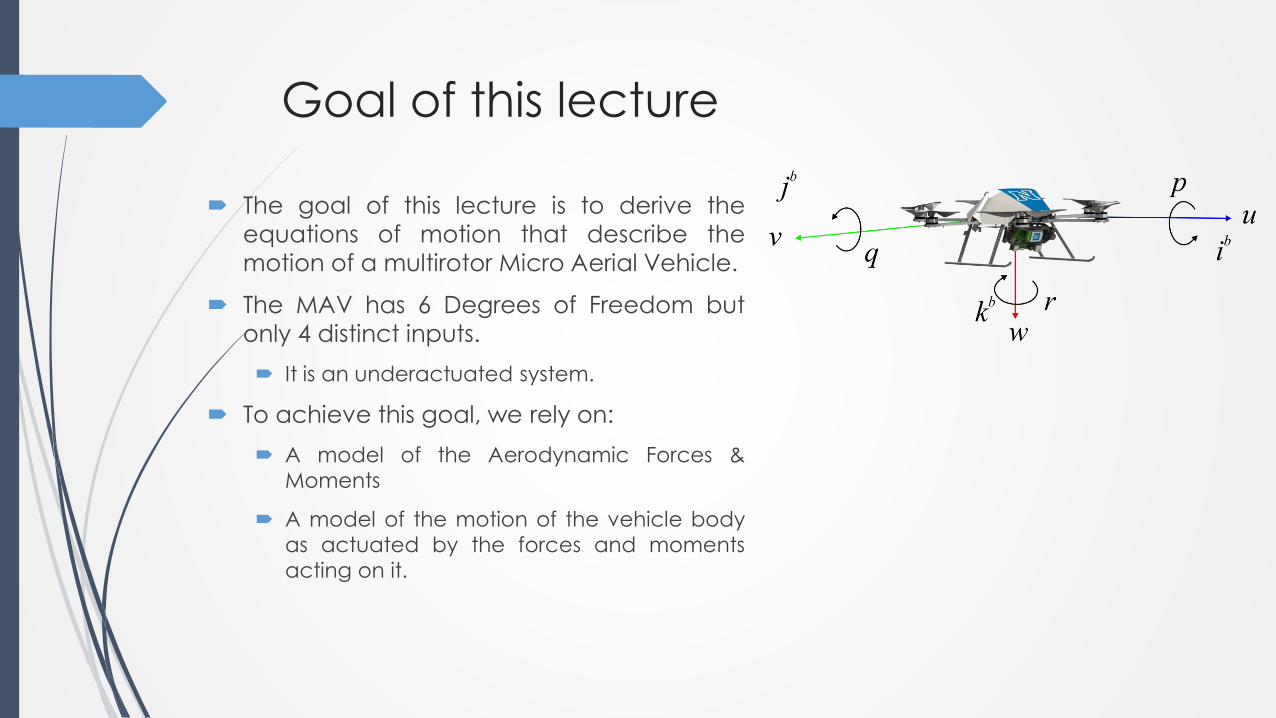
Goal of this lecture
The goal of this lecture is to derive the
equations of motion that describe the
motion of a multirotor Micro Aerial Vehicle.
The MAV has 6 Degrees of Freedom but
only 4 distinct inputs.
It is an underactuated system.
To achieve this goal, we rely on:
A model of the Aerodynamic Forces &
Moments
A model of the motion of the vehicle body
as actuated by the forces and moments
acting on it.

The MAV Propeller
The goal of this lecture is to derive the
equations of motion that describe the
motion of a multirotor Micro Aerial Vehicle.
To achieve this goal, we rely on:
A model of the Aerodynamic Forces &
Moments
A model of the motion of the vehicle body
as actuated by the forces and moments
acting on it.

The MAV Propeller
Is something much simpler than a helicopter rotor

The MAV Propeller
Video of airflow and vortex patterns with propellers. These tests were conducted at NACA, nowNASA Langley Research Center. The interior tests were probably at the Propeller Research Tunnel.The exterior tests at the end of the film were at the Helicopter Test Tower. Langley Film #L-118
The MAV Propeller
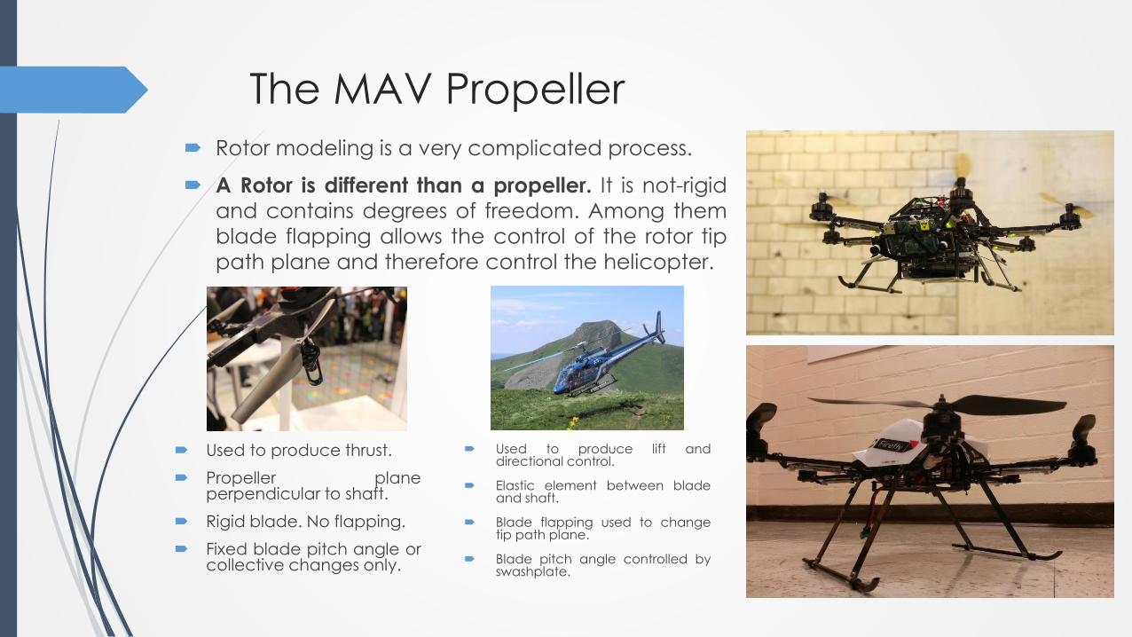
Rotor modeling is a very complicated process.
A Rotor is different than a propeller. It is not-rigid
and contains degrees of freedom. Among them
blade flapping allows the control of the rotor tip
path plane and therefore control the helicopter.
Used to produce lift anddirectional control.
Elastic element between bladeand shaft.
Blade flapping used to changetip path plane.
Blade pitch angle controlled byswashplate.
Used to produce thrust.
Propeller planeperpendicular to shaft.
Rigid blade. No flapping.
Fixed blade pitch angle orcollective changes only.

The MAV Propeller
Simplified model forces and moments:
Thrust Force: the resultant of the vertical forces acting on
all the blade elements.
Hub Force: the resultant of all the horizontal forces acting
on all the blade elements.
Drag Moment: This moment about the rotor shaft is
caused by the aerodynamic forces acting on the blade
elements. The horizontal forces acting on the rotor are
multiplied by the moment arm and integrated over the
rotor. Drag moment determines the power required to
spin the rotor.
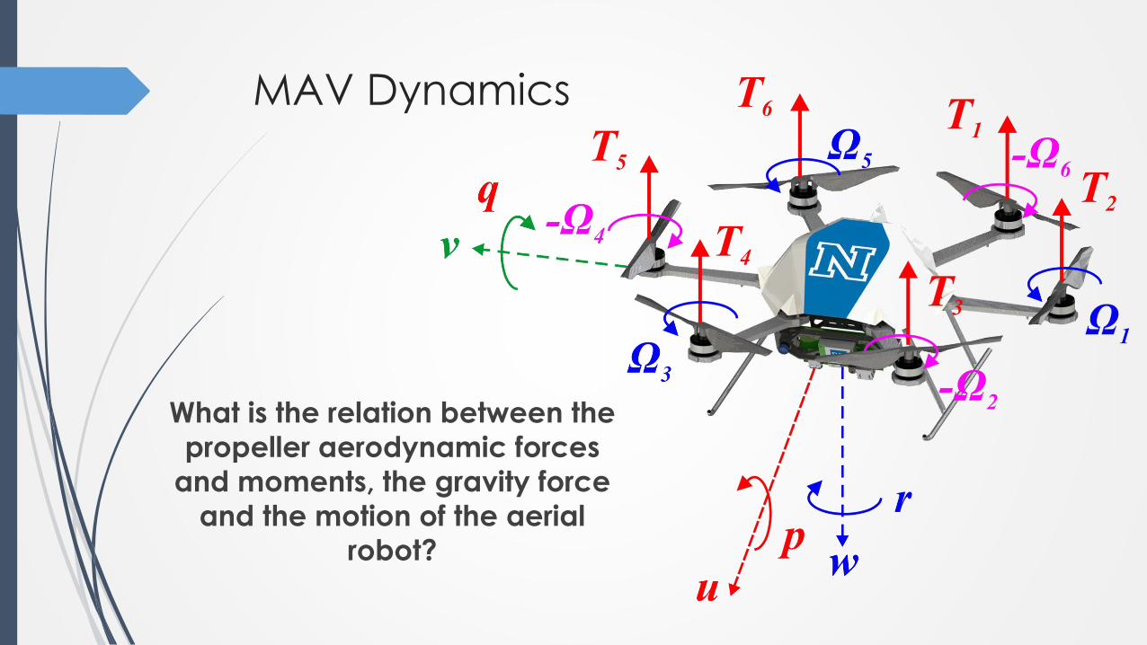
MAV Dynamics
What is the relation between the
propeller aerodynamic forces
and moments, the gravity force
and the motion of the aerial
robot?

MAV Dynamics
Assumption 1: the Micro Aerial Vehicle is flying as a
rigid body with negligible aerodynamic effects on it –
for the employed airspeeds.
The propeller is considered as a simple propeller disc
that generates thrust and a moment around its shaft.
Recall:
And let us write:

MAV Dynamics
Recall the kinematic equations:
Translational Kinematic Expression:
Rotational Kinematic Expression

MAV Dynamics
Recall Newton’s 2nd Law:
f is the summary of all external forces
m is the mass of the robot
Time derivative is taken wrt the interial frame
Using the expression:
Which expressed in the body frame:

MAV Dynamics
Where
Therefore:

MAV Dynamics
Recall Newton’s 2nd Law:
h is the angular momentum vector
m is the summary of all external moments
Time derivative is taken wrt the interial frame
Therefore:
Which expressed in the body frame:

MAV Dynamics
Recall Newton’s 2nd Law:
h is the angular momentum vector
m is the summary of all external moments
Time derivative is taken wrt the interial frame
Therefore:
Which expressed in the body frame:

MAV Dynamics
For a rigid body, the angular momentum is defined as
the product of the inertia matrix and the angular
velocity vector:
where
But as the multirotor MAV is symmetric:
MAV Dynamics
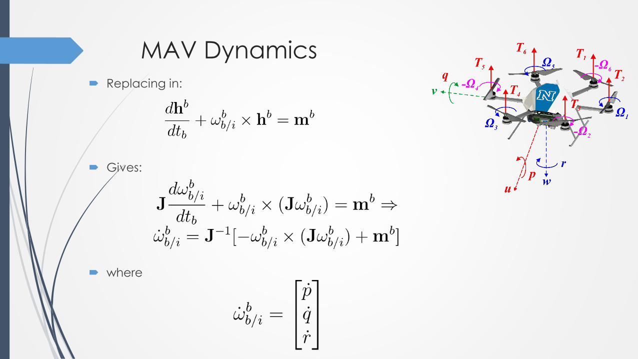
Replacing in:
Gives:
where

MAV Dynamics
By setting the moments vector:
Then for the symmetric MAV, equation:
Becomes:

MAV Dynamics To append the forces and moments we need to
combine their formulation with
Next step: append the MAV forces
and moments

MAV Dynamics
MAV forces in the body frame:
Moments in the body frame:

MAV Dynamics
MAV forces in the body frame:
Moments in the body frame:

Code Example
MATLAB Quadrotor Simulator:
https://github.com/unr-arl/drones_demystified/tree/master/matlab/vehicle-dynamics
Accurate dynamics simulator with further realistic features on sensing data and planning
algorithms.
Create by: Ke Sun, University of Pennsylvania
run “quad_sim.m”
ROS/Gazebo Multirotor Simulator:
http://www.autonomousrobotslab.com/rotors-simulator2.html
Advanced aerial robots simulator, recreating real-life autonomous operation in terms of actuation, dynamics, control
systems, sensor systems, localization algorithms, as well as path planning.
Very realistic – relying on Gazebo and physics engine.
roslaunch rotors_gazebo mav_hovering_example.launch mav_name:=firefly world_name:=basic

Find out more
S. Leutenegger,C. Huerzeler, A.K. Stowers, K. Alexis, M. Achtelik, D. Lentink, P.
Oh, and R. Siegwart. "Flying Robots", Handbook of Robotics (upcoming new
version – available upon request).
Python? http://www.autonomousrobotslab.com/simulations-with-simpy.html
Help with Differential Equations?
https://www.khanacademy.org/math/differential-equations
Always check: http://www.kostasalexis.com/literature-and-links1.html

Thank you! Please ask your question!