Enable the Timer Unit -...
13
94-00-00-01 - 1 - Cobham Semiconductor Solutions Version 1.0.1 Cobham.com/HiRel Table 1: Cross Reference of Applicable Products PRODUCT NAME MANUFACTURER PART NUMBER SMD # DEVICE TYPE INTERNAL PIC NUMBER UT700 LEON UT700 5962-13238 Timer Unit WQ03 1.0 Overview The Timer Unit has a long history of being a part of the computer system's world. Although the Timer Unit operations are limited to counting, comparing and triggering, its role is invaluable. In an Operating System, the Timer Unit allows the scheduler to deterministically check for the next task ready-to-run, while in a TCP/IP stack, the Timer Unit acts as a heartbeat to the communication stack to process incoming data at a constant time interval. Besides these two examples, we can use the timer unit to generate Pulse Width Modulation (PWM) to control motors, produce simple Digital- to-Analog Conversion (DAC) output, etc. The UT700 LEON 3FT SPARC TM Processor provides one Timer Unit consisting of four 32-bit timers. Each timer can operate independently, or in chain mode. In chain mode, we can chain up to four timers to provide a higher count value. In this Application Note, we explore the Timer Unit features and how to program it. Note: The description in this application note describes how to directly use the memory mapped interface of a specific hardware peripheral. If you are using an operating system such as RTEMS, Linux, and VxWorks or an environment such as BCC then it is recommended to use the infrastructure provided by those environments instead of accessing the peripheral directly as described in this application note. 2.0 Application Note Layout This application note (AN) starts by providing a brief description of the Timer Unit memory map, the associated registers, and the timers. The description of the Timer Unit falls under the Timer Unit Hardware sections. Standard Product Enable the Timer Unit UT700 LEON 3FT Application Note Cobham.com/HiRel September 29, 2017 The most important thing we build is trust
-
Upload
truongcong -
Category
Documents
-
view
218 -
download
2
Transcript of Enable the Timer Unit -...

94-00-00-01 - 1 - Cobham Semiconductor Solutions Version 1.0.1 Cobham.com/HiRel
Table 1: Cross Reference of Applicable Products
PRODUCT NAME MANUFACTURER PART NUMBER
SMD # DEVICE TYPE INTERNAL PIC
NUMBER UT700 LEON UT700 5962-13238 Timer Unit WQ03
1.0 Overview
The Timer Unit has a long history of being a part of the computer system's world. Although the Timer Unit operations are limited to counting, comparing and triggering, its role is invaluable.
In an Operating System, the Timer Unit allows the scheduler to deterministically check for the next task ready-to-run, while in a TCP/IP stack, the Timer Unit acts as a heartbeat to the communication stack to process incoming data at a constant time interval. Besides these two examples, we can use the timer unit to generate Pulse Width Modulation (PWM) to control motors, produce simple Digital-to-Analog Conversion (DAC) output, etc.
The UT700 LEON 3FT SPARCTM Processor provides one Timer Unit consisting of four 32-bit timers. Each timer can operate independently, or in chain mode. In chain mode, we can chain up to four timers to provide a higher count value.
In this Application Note, we explore the Timer Unit features and how to program it.
Note: The description in this application note describes how to directly use the memory mapped interface of a specific hardware peripheral. If you are using an operating system such as RTEMS, Linux, and VxWorks or an environment such as BCC then it is recommended to use the infrastructure provided by those environments instead of accessing the peripheral directly as described in this application note.
2.0 Application Note Layout
This application note (AN) starts by providing a brief description of the Timer Unit memory map, the associated registers, and the timers. The description of the Timer Unit falls under the Timer Unit Hardware sections.
Standard Product
Enable the Timer Unit UT700 LEON 3FT
Application Note Cobham.com/HiRel
September 29, 2017 The most important thing we build is trust

94-00-00-01 - 2 - Cobham Semiconductor Solutions Version 1.0.1 Cobham.com/HiRel
After the Timer Unit Hardware sections, this AN provides a high-level flow diagram to depict the correct sequential steps to initialize the Timer Unit. We describe each block in the order as shown in the flow diagram. The description of the flow diagram falls under the Timer Unit Initialization sections.
Finally, we apply this knowledge using C programming code to enable the UT700 Timer Unit to show its capabilities. The C code programming examples fall under the Timer Unit Programming sections.
These subsections are described in detail below:
Timer Unit Hardware Timer Unit Initialization
Timer Unit Programming
3.0 Timer Unit Hardware
The Timer Unit is mapped to the memory region from 0x8000_0300 to 0x8000_0348. It has 15 registers; two registers for the Prescaler, one configuration register and four set of three registers for each timer. For more information about each register, refer to Chapter 7 of the UT700 Functional Manual.
In the following subsections, we explore the details of the Timer Unit’s prescaler and timers.
3.1 Timer Unit 12-bit Prescaler
The system clock drives the Prescaler to provide the maximum count resolution to the 32-bit timers. The Prescaler includes a hardwired self-reloading logic when the Scalar Value Register (TIMSVR) value underflows, it automatically reloads the user preset value from the Scalar Reload Value Register (TIMSRVR) and sends out a triggering pulse (tick) to the 32-bit timers.
The 32-bit timers share the same decrementer to reduce the Timer Unit’s design gate count; hence, it requires four clock cycles to decrement all the four timers. Therefore, to prevent any interruption from the Prescaler while the timers are decrementing, the minimum Prescaler division factor is 5 (SCALER_RELOAD_VALUE=4). Refer to Chapter 7 of the UT700 Functional Manual for more details.
Note: The minimum Prescaler division factor is 5 (SCALER_RELOAD_VALUE=4).
3.2 Timer Unit Configuration Register
The Configuration Register (TIMTCR) provides a Disable Timer Freeze (DF) bit to freeze the timer during debug. The remaining configuration bits in the TIMTCR are read only.

94-00-00-01 - 3 - Cobham Semiconductor Solutions Version 1.0.1 Cobham.com/HiRel
3.3 Timer Unit Four 32-bit Timers
Unlike the Prescaler, refer to Section 3.1, the Timers reload logic is programmable. The programmer needs to set the Restart (RS) bit in the Timer Control Register (TIMCTR) to enable automatic reloading when the timers underflow.
Each timer is also capable of generating an interrupt when the timer underflows if the Interrupt Enable (IE) bit is set.
Note: The timer interrupt numbers are 6 to 9 for timer 1 to timer 4, respectively.
3.3.1 Chaining of Timers
The Timer Unit provides a feature to chain the timers. This feature allows the chaining of two to four timers to increase the count value as shown in Figure 1 to Figure 3.
Timer1 Timer2 Timer2 Timer3 Timer3 Timer4
CH=0 CH=1 CH=0 CH=1 CH=0 CH=1
Figure 1: Chain of Two Timers
Timer1 Timer2 Timer3 Timer2 Timer3 Timer4
CH=0 CH=1 CH=1 CH=0 CH=1 CH=1
Figure 2: Chain of There Timers
Timer1 Timer2 Timer3 Timer4
CH=0 CH=1 CH=1 CH=1
Figure 3: Chain of Four Timers
Note: To chain the Timers, set the Chain (CH) bit in the succeeding timer TIMCTR.

94-00-00-01 - 4 - Cobham Semiconductor Solutions Version 1.0.1 Cobham.com/HiRel
3.3.2 Timer 4, Watchdog Timer
Timer 4 can function as a general purpose timer and as a watchdog timer. We configure Timer 4 as a watchdog timer by setting the EN bits in Timer 4 TIMCTR register and connecting the watchdog output signal (𝐖𝐃𝐎𝐆̅̅ ̅̅ ̅̅ ̅̅ ̅) to the system reset circuitry.
4.0 Timer Unit Initialization
The Timers can function as simple counters for time elapse calculation or as an asynchronous time expiration notification mechanisms. To initialize a timer as a simple counter, set the TIMRVR with a value (normally, 0xFFFF_FFFF) and set the following bits in the TIMCTR register:
LD: load the value from TIMRVR to TIMCVR immediately
RS: Reload the value from TIMRVR to TIMCVR when the timer underflows
EN: Enable the timer
As an asynchronous time expiration notification mechanism, the initialization involves setting up interrupt sub-routine as shown in Figure 4. We only elaborate the Enable Peripheral Interrupt steps here. For the remaining initialization steps, refer to the Enable the Interrupt Controller Module application note from our website (www.cobham.com/HiRel).
STARTDisable All Interrupts
Attach ISR to Interrupt
Enable Peripheral Interrupt
Enable Interrupt(s)
End
Define the ISR
Figure 4: Timers Interrupt Initialization Steps
To enable the peripheral interrupt, set the IE bit in the TIMCTR. The other bit settings are similar to the settings of a simple counter.

94-00-00-01 - 5 - Cobham Semiconductor Solutions Version 1.0.1 Cobham.com/HiRel
5.0 Timer Unit Programming
We learned from Section 4.0 that the Timer Unit has several features. We can chain the timers to increase the count value, generate asynchronous time expiration notification, as a simple counter for time elapse calculation, etc. We can also use timer 4 as a watchdog timer. In the following sections, we provide programming examples to enable some of these features.
5.1 Timer Unit 12-bit Prescaler
The Timer Unit Prescaler has two registers, TIMSVR and TMSRVR. The following code example (Code 1) shows how to program the Prescaler. TIMERUNIT.TIMSRVR.R = 0x04; // set a value in the scale reload value register TIMERUNIT.TIMSVR.R = 0x04; // set a value in the scale value register
Code 1: Setup Prescaler
Note: The minimum Prescaler division factor is 5 (SCALER_RELOAD_VALUE=4).
5.2 Timer Unit Configuration Register
The Timer Unit Configuration Register provides a DF bit to freeze the timers during debug, and this is how to program it (Code 2).
TIMERUNIT.TIMCR.B.DF = 0; // Freeze Timer Unit during Debug
Code 2: Setup Configuration Register
5.3 Timer Unit 32-bit Timers
In this example, we program the timer to provide asynchronous time expiration notification (Code 3 and Code 4). By clearing the IE bit, we program the timer as a simple counter. Setting a value in the TIMSVR and TIMSRVR register:
See Section 5.1, Code 1. X = 0, 1, 2, and 3
TIMERUNIT.TIMER[X].TIMCVR.R = 0xFFFF; // set a value in the TIMCVR

94-00-00-01 - 6 - Cobham Semiconductor Solutions Version 1.0.1 Cobham.com/HiRel
TIMERUNIT.TIMER[X].TIMRVR.R = 0xFFFF; // set a reload value in the TIMRVR
Code 3: Setup Timer Counter Value and Reload Counter Value Register
Setting the TIMCTR bits for operation: X = 0, 1, 2, and 3 TIMERUNIT.TIMER[X].CTR.B.CH = 0; // set to chain preceding timer TIMERUNIT.TIMER[X].CTR.B.IP = 0; // Interrupt pending TIMERUNIT.TIMER[X].CTR.B.IE = 1; // Interrupt enable TIMERUNIT.TIMER[X].CTR.B.LD = 1; // load the value in TIMRVR to TIMCVR TIMERUNIT.TIMER[X].CTR.B.RS = 1; // restart counter with the value in TIMRVR TIMERUNIT.TIMER[X].CTR.B.EN = 1; // enable the timer
Code 4: Setup Timer Control Register
5.4 Chaining of Timers
The following programming examples show how to chain the timers with interrupt enable, see Figure 1 to Figure 3 and Code 5 to Code 7 respectively. Setting a value in the TIMSVR and TIMSRVR register:
See Section 5.1, Code 1. Setting a value in the TIMCVR and TIMRVR register: See Section 5.3, Code 3.
5.4.1 Chaining of Two Timers
Timer N: N = 1, 2, 3, and 4; X = 1, 2, and 3 TIMERUNIT.TIMER[X].CTR.B.CH = 1; // set to chain preceding timer TIMERUNIT.TIMER[X].CTR.B.IP = 0; // Interrupt pending TIMERUNIT.TIMER[X].CTR.B.IE = 1; // Interrupt enable TIMERUNIT.TIMER[X].CTR.B.LD = 1; // load the value in TIMRVR to TIMCVR TIMERUNIT.TIMER[X].CTR.B.RS = 1; // restart counter with the value in TIMRVR TIMERUNIT.TIMER[X].CTR.B.EN = 1; // enable the timer Timer N-1: X = 0, 1, and 2
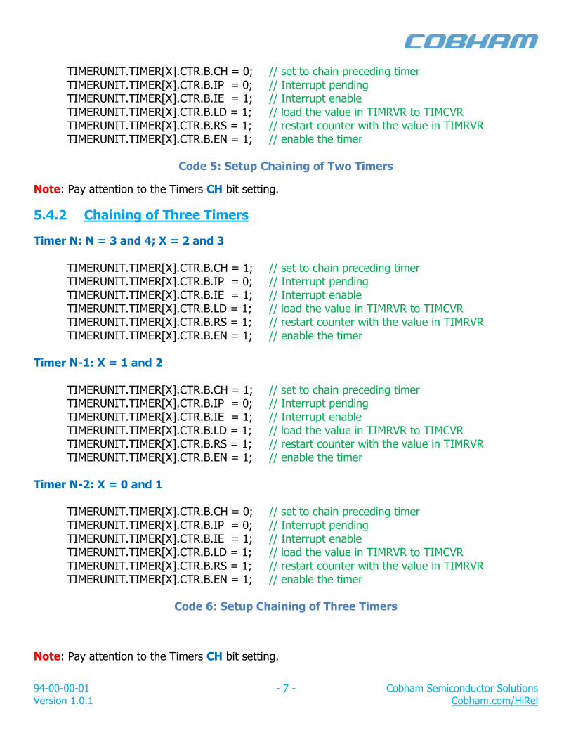
94-00-00-01 - 7 - Cobham Semiconductor Solutions Version 1.0.1 Cobham.com/HiRel
TIMERUNIT.TIMER[X].CTR.B.CH = 0; // set to chain preceding timer TIMERUNIT.TIMER[X].CTR.B.IP = 0; // Interrupt pending TIMERUNIT.TIMER[X].CTR.B.IE = 1; // Interrupt enable TIMERUNIT.TIMER[X].CTR.B.LD = 1; // load the value in TIMRVR to TIMCVR TIMERUNIT.TIMER[X].CTR.B.RS = 1; // restart counter with the value in TIMRVR TIMERUNIT.TIMER[X].CTR.B.EN = 1; // enable the timer
Code 5: Setup Chaining of Two Timers
Note: Pay attention to the Timers CH bit setting.
5.4.2 Chaining of Three Timers
Timer N: N = 3 and 4; X = 2 and 3 TIMERUNIT.TIMER[X].CTR.B.CH = 1; // set to chain preceding timer TIMERUNIT.TIMER[X].CTR.B.IP = 0; // Interrupt pending TIMERUNIT.TIMER[X].CTR.B.IE = 1; // Interrupt enable TIMERUNIT.TIMER[X].CTR.B.LD = 1; // load the value in TIMRVR to TIMCVR TIMERUNIT.TIMER[X].CTR.B.RS = 1; // restart counter with the value in TIMRVR TIMERUNIT.TIMER[X].CTR.B.EN = 1; // enable the timer Timer N-1: X = 1 and 2 TIMERUNIT.TIMER[X].CTR.B.CH = 1; // set to chain preceding timer TIMERUNIT.TIMER[X].CTR.B.IP = 0; // Interrupt pending TIMERUNIT.TIMER[X].CTR.B.IE = 1; // Interrupt enable TIMERUNIT.TIMER[X].CTR.B.LD = 1; // load the value in TIMRVR to TIMCVR TIMERUNIT.TIMER[X].CTR.B.RS = 1; // restart counter with the value in TIMRVR TIMERUNIT.TIMER[X].CTR.B.EN = 1; // enable the timer Timer N-2: X = 0 and 1 TIMERUNIT.TIMER[X].CTR.B.CH = 0; // set to chain preceding timer TIMERUNIT.TIMER[X].CTR.B.IP = 0; // Interrupt pending TIMERUNIT.TIMER[X].CTR.B.IE = 1; // Interrupt enable TIMERUNIT.TIMER[X].CTR.B.LD = 1; // load the value in TIMRVR to TIMCVR TIMERUNIT.TIMER[X].CTR.B.RS = 1; // restart counter with the value in TIMRVR TIMERUNIT.TIMER[X].CTR.B.EN = 1; // enable the timer
Code 6: Setup Chaining of Three Timers
Note: Pay attention to the Timers CH bit setting.
94-00-00-01 - 8 - Cobham Semiconductor Solutions Version 1.0.1 Cobham.com/HiRel
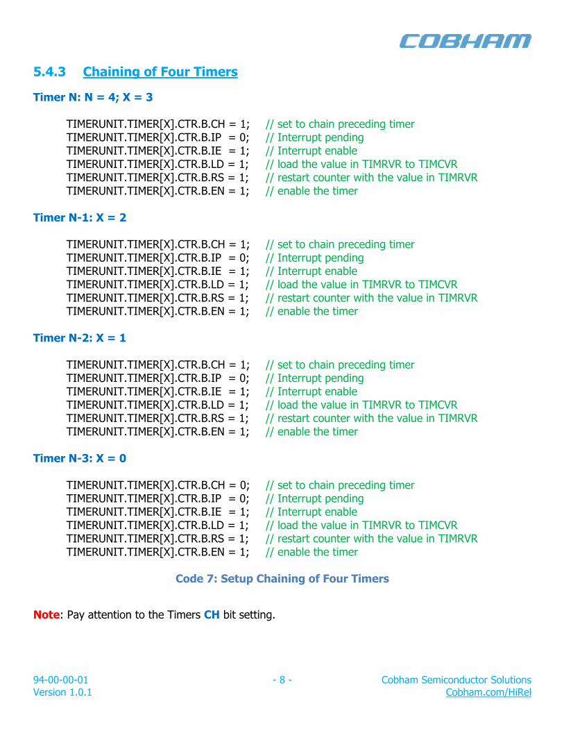
5.4.3 Chaining of Four Timers
Timer N: N = 4; X = 3 TIMERUNIT.TIMER[X].CTR.B.CH = 1; // set to chain preceding timer TIMERUNIT.TIMER[X].CTR.B.IP = 0; // Interrupt pending TIMERUNIT.TIMER[X].CTR.B.IE = 1; // Interrupt enable TIMERUNIT.TIMER[X].CTR.B.LD = 1; // load the value in TIMRVR to TIMCVR TIMERUNIT.TIMER[X].CTR.B.RS = 1; // restart counter with the value in TIMRVR TIMERUNIT.TIMER[X].CTR.B.EN = 1; // enable the timer Timer N-1: X = 2 TIMERUNIT.TIMER[X].CTR.B.CH = 1; // set to chain preceding timer TIMERUNIT.TIMER[X].CTR.B.IP = 0; // Interrupt pending TIMERUNIT.TIMER[X].CTR.B.IE = 1; // Interrupt enable TIMERUNIT.TIMER[X].CTR.B.LD = 1; // load the value in TIMRVR to TIMCVR TIMERUNIT.TIMER[X].CTR.B.RS = 1; // restart counter with the value in TIMRVR TIMERUNIT.TIMER[X].CTR.B.EN = 1; // enable the timer Timer N-2: X = 1 TIMERUNIT.TIMER[X].CTR.B.CH = 1; // set to chain preceding timer TIMERUNIT.TIMER[X].CTR.B.IP = 0; // Interrupt pending TIMERUNIT.TIMER[X].CTR.B.IE = 1; // Interrupt enable TIMERUNIT.TIMER[X].CTR.B.LD = 1; // load the value in TIMRVR to TIMCVR TIMERUNIT.TIMER[X].CTR.B.RS = 1; // restart counter with the value in TIMRVR TIMERUNIT.TIMER[X].CTR.B.EN = 1; // enable the timer Timer N-3: X = 0 TIMERUNIT.TIMER[X].CTR.B.CH = 0; // set to chain preceding timer TIMERUNIT.TIMER[X].CTR.B.IP = 0; // Interrupt pending TIMERUNIT.TIMER[X].CTR.B.IE = 1; // Interrupt enable TIMERUNIT.TIMER[X].CTR.B.LD = 1; // load the value in TIMRVR to TIMCVR TIMERUNIT.TIMER[X].CTR.B.RS = 1; // restart counter with the value in TIMRVR TIMERUNIT.TIMER[X].CTR.B.EN = 1; // enable the timer
Code 7: Setup Chaining of Four Timers
Note: Pay attention to the Timers CH bit setting.

94-00-00-01 - 9 - Cobham Semiconductor Solutions Version 1.0.1 Cobham.com/HiRel
5.5 Timer 4, Watchdog Timer
This programming example shows how to program the Timer 4 as a watchdog timer (Code 8).
Timer 4: X = 3 TIMERUNIT.TIMER[X].CTR.B.CH = 0; // set to chain preceding timer TIMERUNIT.TIMER[X].CTR.B.IP = 0; // Interrupt pending TIMERUNIT.TIMER[X].CTR.B.IE = 0; // Interrupt enable TIMERUNIT.TIMER[X].CTR.B.LD = 1; // load the value in TIMRVR to TIMCVR TIMERUNIT.TIMER[X].CTR.B.RS = 0; // restart counter with the value in TIMRVR TIMERUNIT.TIMER[X].CTR.B.EN = 1; // enable the timer
Code 8: Setup the Watchdog
Note: The watchdog output signal (𝐖𝐃𝐎𝐆̅̅ ̅̅ ̅̅ ̅̅ ̅) is connected to the system reset circuitry.
5.5.1 Watchdog Timer, Kick the Dog
The system needs to reload the Timer 4 counter value periodically to prevent the watchdog from resetting the system (when Timer 4 underflows); this is how to reload Timer 4 counter value (Code 9): Timer 4: X = 3
TIMERUNIT.TIMER[X].CTR.B.LD = 1; // load the value in TIMRVR to TIMCVR
Code 9: Kick the Dog
Note: Use LD bit to kick the dog.
6.0 Summary and Conclusion
After going through this AN, the reader should know how to enable the Timer Unit, how to setup the timers for the different modes of operation and how to chain the different timers.
For more information about our UT700 LEON 3FT/SPARC™ V8 Microprocessor and other products please visit our website, www.cobham.com/HiRel or email us at [email protected].
94-00-00-01 - 10 - Cobham Semiconductor Solutions Version 1.0.1 Cobham.com/HiRel
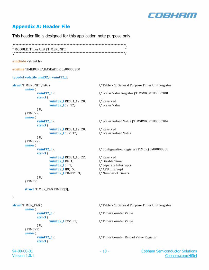
Appendix A: Header File
This header file is designed for this application note purpose only. /****************************************************************************\ * MODULE: Timer Unit (TIMERUNIT) * \****************************************************************************/ #include <stdint.h> #define TIMERUNIT_BASEADDR 0x80000300 typedef volatile uint32_t vuint32_t; struct TIMERUNIT _TAG { // Table 7.1: General Purpose Timer Unit Register
union { vuint32_t R; // Scalar Value Register (TIMSVR) 0x80000300 struct {
vuint32_t RES31_12: 20; // Reserved vuint32_t SV: 12; // Scaler Value
} B; } TIMSVR; union {
vuint32_t R; // Scaler Reload Value (TIMSRVR) 0x80000304 struct {
vuint32_t RES31_12: 20; // Reserved vuint32_t SRV: 12; // Scaler Reload Value
} B; } TIMSRVR; union {
vuint32_t R; // Configuration Register (TIMCR) 0x80000308 struct {
vuint32_t RES31_10: 22; // Reserved vuint32_t DF: 1; // Disable Timer vuint32_t SI: 1; // Separate Interrupts vuint32_t IRQ: 5; // APB Interrupt vuint32_t TIMERS: 3; // Number of Timers
} B; } TIMCR; struct TIMER_TAG TIMER[3];
}; struct TIMER_TAG { // Table 7.1: General Purpose Timer Unit Register
union { vuint32_t R; // Timer Counter Value struct {
vuint32_t TCV: 32; // Timer Counter Value } B;
} TIMCVR; union {
vuint32_t R; // Timer Counter Reload Value Register struct {
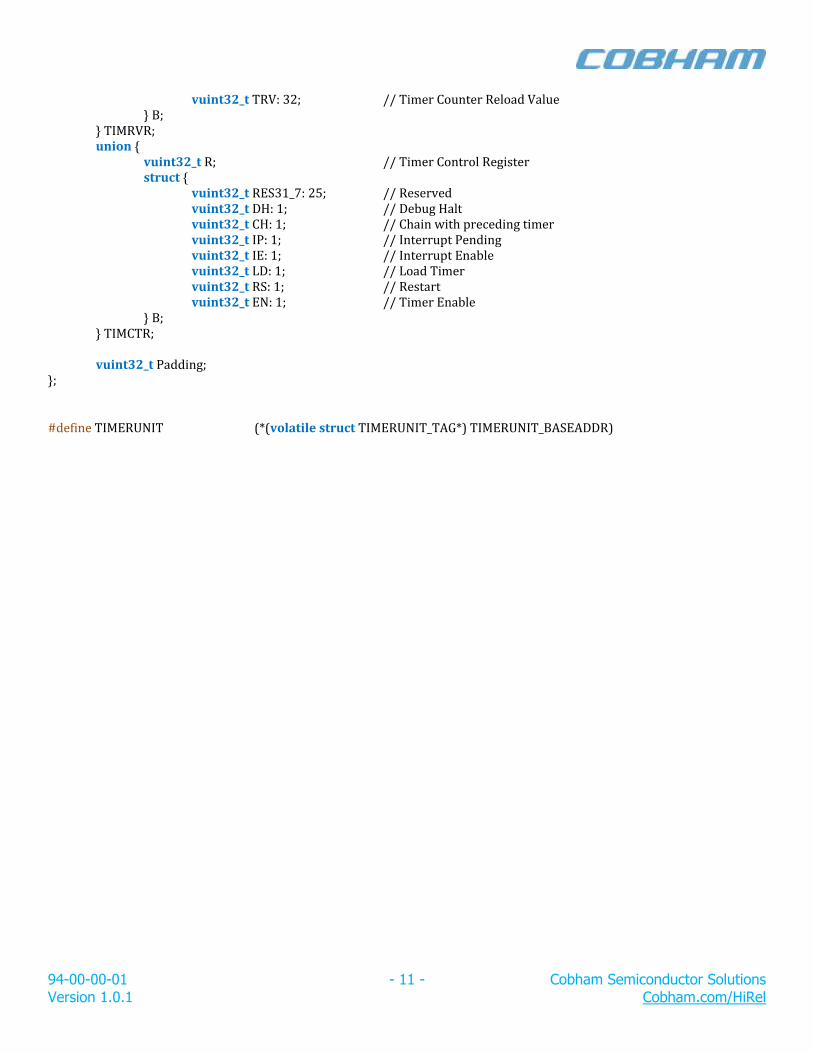
94-00-00-01 - 11 - Cobham Semiconductor Solutions Version 1.0.1 Cobham.com/HiRel
vuint32_t TRV: 32; // Timer Counter Reload Value } B;
} TIMRVR; union {
vuint32_t R; // Timer Control Register struct {
vuint32_t RES31_7: 25; // Reserved vuint32_t DH: 1; // Debug Halt vuint32_t CH: 1; // Chain with preceding timer vuint32_t IP: 1; // Interrupt Pending vuint32_t IE: 1; // Interrupt Enable vuint32_t LD: 1; // Load Timer vuint32_t RS: 1; // Restart vuint32_t EN: 1; // Timer Enable
} B; } TIMCTR; vuint32_t Padding;
};
#define TIMERUNIT (*(volatile struct TIMERUNIT_TAG*) TIMERUNIT_BASEADDR)

94-00-00-01 - 12 - Cobham Semiconductor Solutions Version 1.0.1 Cobham.com/HiRel
REVISION HISTORY Date Rev. # Author Change Description
03/20/2017 1.0.0 MTS Initial Release
09/29/2017 1.0.1 MTS Add note, page 1
94-00-00-01 - 13 - Cobham Semiconductor Solutions Version 1.0.0 www.cobham.com/HiRel
Cobham Semiconductor Solutions
Cobham Semiconductor Solutions 4350 Centennial Blvd Colorado Springs, CO 80907 E: [email protected] T: 800 645 8862 Aeroflex Colorado Springs Inc., DBA Cobham Semiconductor Solutions, reserves the right to make changes to any products and services described herein at any time without notice. Consult Aeroflex or an authorized sales representative to verify that the information in this data sheet is current before using this product. Aeroflex does not assume any responsibility or liability arising out of the application or use of any product or service described herein, except as expressly agreed to in writing by Aeroflex; nor does the purchase, lease, or use of a product or service from Aeroflex convey a license under any patent rights, copyrights, trademark rights, or any other of the intellectual rights of Aeroflex or of third parties.
This product is controlled for export under the U.S. Department of Commerce (DoC). A license may be required prior to the export of this product from the United States.