ENA ER G85 Issue 2 Draft for Approval · Electricity Distribution Licensee The holder of a licence...
37
PRODUCED BY THE ENGINEERING DIRECTORATE OF THE ENERGY NETWORKS ASSOCIATION Engineering Recommendation G85 Issue 2 – December 2007 Innovation Good Practice Guide for Energy Networks energynetworks.org
-
Upload
nguyenxuyen -
Category
Documents
-
view
217 -
download
1
Transcript of ENA ER G85 Issue 2 Draft for Approval · Electricity Distribution Licensee The holder of a licence...

PRODUCED BY THE ENGINEERING DIRECTORATE OF THE ENERGY NETWORKS ASSOCIATION
Engineering Recommendation G85
Issue 2 – December 2007
Innovation Good Practice Guide for Energy Networks
energynetworks.org

© 2007 Energy Networks Association
All rights reserved. No part of this publication may be reproduced, stored in a retrieval system or transmitted in any form or by any means, electronic, mechanical, photocopying,
recording or otherwise, without the prior written consent of Energy Networks Association. Specific enquiries concerning this
document should be addressed to:
Engineering Directorate Energy Networks Association
18 Stanhope Place Marble Arch
London W2 2HH
This document has been prepared for use by members of the Energy Networks Association to take account of the conditions
which apply to them. Advice should be taken from an appropriately qualified engineer on the suitability of this
document for any other purpose.

ENA Engineering Recommendation G85 Issue 2 December 2007
Page 3
Page 3
CONTENTS 1 INTRODUCTION......................................................................................................... 7
1.1 Context ........................................................................................................... 7 1.2 Who is this guide intended for?................................................................... 8 1.3 Purpose of this guide.................................................................................... 8
2 IFI PROJECTS – OUTLINE........................................................................................ 9
3 IFI ELIGIBLE WORK ................................................................................................ 10
3.1 Technical Development .............................................................................. 10 3.2 Degree of Innovation................................................................................... 11 3.3 Potential Project Benefits (Customer Value) ............................................ 12
4 DEVELOPMENT AND MANAGEMENT OF IFI PROJECTS ................................... 13
4.1 Elements of a Project Proposal.................................................................. 13 4.2 Project Assessment .................................................................................... 14 4.3 Project Authorisation.................................................................................. 18 4.4 Project Management ................................................................................... 18 4.5 Project Completion ..................................................................................... 18
5 ANNUAL REGULATORY REPORTING FOR IFI PROJECTS ................................ 19
5.1 Example IFI Reporting Templates.............................................................. 20
6 IFI PROJECT AUDIT ................................................................................................ 22
7 REFERENCES.......................................................................................................... 22
A APPENDIX A – PROJECT ASSESSMENTS: EXAMPLES ..................................... 23
A.1 Benefits Assessment .................................................................................. 23 A.2 Risk Assessment......................................................................................... 25 A.3 Overall Assessment and Summary ........................................................... 27 A.4 Discussion ................................................................................................... 28
B APPENDIX B – REGISTERED POWER ZONES(RPZ) ........................................... 29
B.1 Outline .......................................................................................................... 29 B.2 RPZ Eligibility .............................................................................................. 29
B.2.1 Demonstration of RPZ Innovation............................................... 29 B.2.2 Further Considerations ................................................................ 30
B.3 Example: Projects that could be considered for RPZs............................ 31
B.3.1 Business parks ............................................................................. 31 B.3.2 Social housing schemes.............................................................. 31 B.3.3 Reception networks...................................................................... 31 B.3.4 Innovation and Benefit assessment for an RPZ ........................ 31
B.4 RPZ Registration ......................................................................................... 31
B4.1 Application timescale................................................................... 31 B.4.2 DNO submission of application to Ofgem.................................. 32 B.4.3 Ofgem’s consideration of applications ...................................... 32
B.5 Ongoing Regulatory Reporting Requirements for RPZ ........................... 33 B.6 Report Formats............................................................................................ 33 B.7 RPZ Example Application........................................................................... 34
B.7.1 Example RPZ Documentation...................................................... 35

ENA Engineering Recommendation G85 Issue 2 December 2007 Page 4
4
TABLES Table 1: IFI Benefits Table.................................................................................................. 15 Table 2: Project Risk Assessment Criteria....................................................................... 17 Table 3: IFI Reporting Requirements - dates.................................................................... 19 Table 4: Summary report of IFI project activities............................................................. 20 Table 5: Individual IFI Project report................................................................................. 21
Table A1: Benefits Assessment for Example Projects (company weightings omitted for simplicity)..................................................................................................... 23
Table A2: Project Risk Assessment.................................................................................. 26 Table A3: Overall Analysis of Results .............................................................................. 28 Table B4: RPZ Reporting Template................................................................................... 34 FIGURES Figure A1: The Development of a Benefit Score from ratings in Table A1.................... 24 Figure A2: Chart showing Project Risks and Mitigation Measures for each Project ... 25 Figure A3: Chart showing Project Residual Risks (Mitigation – Risk)........................... 27 Figure A4: Overview of Projects showing Benefits and Residual Risks....................... 27 Figure A5: Project Scoring based on Composite of Project Benefits and Risks.......... 28
ENA Engineering Recommendation G85 Issue 2 December 2007
Page 5
Page 5
GLOSSARY Definitions of terms used in the document
Applied research Original investigation undertaken to gain new scientific or technical knowledge and directed towards a practical objective
Blue Sky (research) Research projects with no defined application (see also Pure
Research) Combined Distribution Network Revenue
The sum of combined distribution network revenue as defined for price control purposes in the relevant electricity distribution licence in respect of the relevant year
Combined Transmission Network Revenue
The base transmission revenue as defined for price control purposes in the relevant electricity transmission licence in respect of the relevant year or the base NTS TO revenue as defined for price control purposes in the relevant gas transporter licence in respect of the NTS as defined for price control purposes in respect of the formula year
Development Use of scientific or technical knowledge to produce new or
substantially improved materials, devices, products or services, to install new processes or systems prior to the commencement of commercial production or application or substantially improve those already produced or installed.
DPCR Distribution Price Control Review Electricity Distribution Licensee
The holder of a licence authorising participation in the distribution of electricity i.e. a Distribution Network Operator (DNO)
Electricity Transmission Licensee
The holder of a licence authorising participation in the transmission of electricity
External Expenditure Money paid to third parties in the development and delivery of
eligible IFI projects. External expenditure in this context excludes payments to other group companies
Gas Transmission Licensee
The holder of a gas transporter licence in respect of the NTS as defined for price control purposes in respect of the formula year
GPG Good Practice Guide IFI Innovation Funding Incentive Internal Expenditure Network Operator staff time on eligible IFI projects, multiplied by
the appropriate company rates incorporating salary and overheads Network The electricity distribution, electricity transmission and gas
transmission network of a Network Operator Network Operator Means an Electricity Distribution Licensee, Electricity Transmission
licensee or Gas Transmission Licensee

ENA Engineering Recommendation G85 Issue 2 December 2007 Page 6
6
NTS The gas national transmission system Ofgem Office of gas and electricity markets, being the regulatory body for
the gas and electricity Industries Primary Heavy current equipment that carries power currents at voltages
from LV up to and including 400kV Process The development of a process resulting from an IFI development
Programme Management
Organisation and control of a group of related projects
Project Management Organisation and control of an individual project
Quality of Supply (electricity)
Measure of the continuity of power supply to customers and its maintenance within key parameters such as voltage, frequency, customers interrupted, customer minutes lost and harmonic distortion.
Quality of Supply (gas) Measure of the continuity of gas supply to customers and its
maintenance within key parameters such as restoration, pressure of supply and compliance with Gas Safety Management Regulations
Pure research Experimental or theoretical work undertaken to acquire new
scientific or technical knowledge for its own sake rather than directed towards an application
R&D Research and Development RDD&D Research, Development, Demonstration and Deployment
RIG Regulatory Instructions and Guidance provided for in Network Operator’s Licences
RPZ Registered Power Zone
Secondary Ancillary equipment used to protect, control or maintain the Primary plant.
Technical Being of a scientific and/or engineering nature and benefiting the design, construction, commissioning, operation, maintenance and decommissioning and/or improving the direct environmental interactions of the Primary plant and equipment employed in the distribution of electrical energy, transmission of electrical energy and transmission of gas and/or of the secondary plant and equipment employed to control, protect and maintain such Primary plant and equipment.
TPCR Transmission Price Control Review

ENA Engineering Recommendation G85 Issue 2 December 2007
Page 7
Page 7
1 INTRODUCTION During the development of the Distribution Price Control Review (DPCR) that took effect on 1 April 2005, Ofgem proposed two new incentives: the Innovation Funding Incentive (IFI) and Registered Power Zones (RPZ). As part of its proposals, Ofgem made it a requirement for a Distribution Network Operator (DNO) to have in place a good practice guide to innovation management if it wishes to access the IFI and/or RPZ incentives. In the interests of efficiency, the DNOs co-operated to produce a single industry-wide Good Practice Guide (GPG) that, following Ofgem approval, was adopted by all the DNOs. The DTI agreed to provide funding for the production of the GPG: Engineering Recommendation G85, Version 1, 2005 was the result of this process. During the negotiation for the Transmission Price Control Review (TPCR) that took effect on 1 April 2007, and following the success of the introduction of the Innovation Funding Incentive to DNOs, a similar IFI scheme was established for the Electricity Transmission Licensees and Gas Transmission Licensee. Agreement at the ENA R&D Working Group was given to the creation of a common GPG considering solely IFI for electricity distribution, transmission and gas transmission networks; the result of which is this document. Further information and guidance for the electricity distribution RPZ mechanism is provided in both Appendix B of this document and the Regulatory Instructions and Guidance (RIG). Network Operators should, where they consider it appropriate, have their own internal management systems that complement this GPG. However, it is intended that the GPG will establish a common code of practice across the industry and deliver a sense of coherence between the companies.
1.1 Context As part of the DPCR and TPCR, Ofgem has introduced the IFI mechanism. IFI was consulted on as an integral part of the DPCR and TPCR proposals and was widely supported by a large majority of consultees. The primary aim of the incentive is to encourage the Network Operators to apply innovation in the technical development of their networks. Ofgem recognise that innovation has a different risk/reward balance compared with a Network Operator’s core business. The incentives provided by the IFI mechanism are designed to create a risk/reward balance that is consistent with research, development, demonstration and deployment. The IFI is intended to provide funding for projects primarily focused on the technical development of the networks, to deliver value (e.g. financial, quality of supply, environmental, safety) to end consumers. The detail of the DNO IFI mechanism is set out in the Special Licence Condition C3, Standard Licence Condition 51 (for the Distribution Licences), the Electricity Transmission Licensees’ IFI mechanism is set out in the special licence condition J5 Part 3 or special licence condition D5 part 2, and standard licence condition B16 Part C. The Gas Transmission Licensee’s IFI mechanism is set out in Special Condition C8B and Special Condition C14B. They can be summarised as follows. • A Network Operator is allowed to spend up to 0.5% of its Combined Distribution Network
Revenue or its Combined Transmission Network Revenue (subject to a minimum of £500,000) as the case may be on eligible IFI projects. This GPG provides guidance on the required characteristics of such projects.

ENA Engineering Recommendation G85 Issue 2 December 2007 Page 8
8
• Network Operator IFI expenditure that is internal expenditure will be allowed as part of the total IFI expenditure accrued by the Network Operator.
• The Network Operator is allowed recover 80% of its eligible project expenditure via the IFI mechanism within the Network Operator’s Licence.
• Ofgem will not approve IFI projects but Network Operators will have to openly report their IFI activities on an annual basis. These reports will be published on the Ofgem website.
• Ofgem reserves the right to audit IFI activities if this is judged to be necessary in the interests of customers.
In Ofgem’s review of IFI and subsequent Open Letter response of 14th February 2007, the Authority agreed: • A commitment to extend the DPCR4 IFI scheme until the end of DPCR5 with a flat pass-
through rate of 80%; • The removal of the 15% cap on internal IFI expenditure for both distribution and
transmission licences when requested to do so by a licencee; • To work with the industry to review and revise the guidance documents by which IFI is
controlled and managed; the result of which is this document.
1.2 Who is this guide intended for? This GPG has been produced for Network Operators who will be managing IFI programmes. It has been endorsed by the Network Operators and approved by Ofgem as required by the RIGs. It will also be useful in providing guidance to organisations that are likely to be involved in the specification and delivery of IFI projects including manufacturers, academics and consultancies.
1.3 Purpose of this guide The purpose of this guide is to ensure that all projects that are funded by the IFI are: • selected in accordance with the eligibility criteria approved by Ofgem; • managed effectively taking account of the particular characteristics of research,
development and demonstration projects; and reported on in a consistent way as required by Ofgem.
The guide recommends the steps that need to be taken to formulate and deliver projects that are eligible for the IFI. It is not the purpose of this guide to cut across existing management structures within Network Operators and other organisations but rather to give a framework for coherence between companies and to provide a checklist to ensure all the requirements of Ofgem are met. This guide aims to give a high-level view of good practice processes and procedures. It is expected that companies will also employ existing internal processes that complement those recommended by the GPG. This will save additional process resources and minimise the cost of compliance with the guide.

ENA Engineering Recommendation G85 Issue 2 December 2007
Page 9
Page 9
2 IFI PROJECTS – OUTLINE Projects will be judged as eligible within the IFI provided that: • The project satisfies the eligibility criteria described in this guide; • The project has been well managed; and • Reporting requirements have been met. Work that has been approved within an industry recognised or national/governmental programme (e.g. Department for Business Enterprise & Regulatory Reform (BERR) or European Commission Funding under RD,D&D Frameworks) whose terms of reference clearly address innovation in the networks may be considered eligible within IFI if it meets the defined criteria. Co-operation between Network Operators and other organisations to pursue IFI projects is encouraged. In such cases the overall project would be expected to meet the IFI eligibility criteria, it would then be acceptable for each participating Network Operator to use the eligibility case for the overall project. IFI Projects that secure additional funding from outside agencies, such as the BERR or European Commission, will not trigger any clawback of IFI funding by Ofgem. Engagement with industry engineering committees is not considered eligible as this does not constitute a project having a specific target or deliverable. In the event that a Network Operator provides resources to contribute to an eligible IFI project which is led or managed by a third party then those costs incurred by the Network Operator that are not recovered from the third party will be considered to be eligible IFI expenditure. Where the support of such projects results in a net cost to the Network Operator, the Network Operator should demonstrate, at a level appropriate to the costs involved, that the expected benefits to the Network Operator exceed the costs involved. IFI projects by their nature involve risk. It is understood therefore that not all IFI projects will meet their aims and objectives and deliver net benefits. However, it is expected that the benefits from those that do succeed will significantly exceed the overall costs of a Network Operator’s IFI programme.

ENA Engineering Recommendation G85 Issue 2 December 2007 Page 10
10
3 IFI ELIGIBLE WORK The eligibility of IFI projects is judged using a number of criteria including an assessment of the benefits that are expected to be delivered: this assessment will be based on the best available information at the time of project commitment. It is important that Ofgem, in its role as surrogate customer, is satisfied that IFI investments by Network Operators are appropriately expended on truly innovative projects. It is recognised that a proportion of IFI projects will not deliver the benefits identified; however innovative projects often deliver value in ways that were not anticipated at the start of the project. This section gives guidance on deciding whether a project is eligible within IFI. The definition of an eligible IFI project, as agreed with Ofgem, is: A project will qualify as an eligible IFI project provided that it is designed to enhance the technical development of gas transmission and electricity transmission and distribution networks. Eligible IFI projects will embrace aspects of transmission and distribution system asset management from design through to construction, commissioning, operation, maintenance and decommissioning. Eligible IFI projects will meet three key criteria, together with the above definition, to qualify as a project for IFI funding. The criteria are:
• Technical Development – whether the project is of a technical nature and related to enhancing the technical performance of a Network Operator’s network;
• Degree of Innovation – the project will demonstrate at least Incremental Innovation as described in [3.2] below; and
• Customer value – whether sufficient value (financial or non-financial) is delivered to end consumers if the project is successful.
Sections 3.1 to 3.3 give an indication of the level of technical development, innovation and customer value required to be eligible and provide guidance on meeting these criteria.
3.1 Technical Development An eligible IFI project must enhance the technical development of the network according to the following definition: Being of a scientific and/or engineering nature and benefiting the design, construction, commissioning, operation, maintenance and decommissioning and/or improving the direct environmental interactions of the Primary plant and equipment employed in the distribution of electrical energy, transmission of electrical energy and transmission of gas and/or of the secondary plant and equipment employed to control, protect and maintain such Primary plant and equipment. Projects that address innovation impacting on the performance of networks, including the quality of supply, such as generation, load and storage, are eligible provided that the projects can demonstrate a clear potential to enhance the technical development of the network. Projects which aim to develop a new process are eligible providing that the new process can demonstrate a clear potential to enhance the technical development of the network. Development of a purely non-technical management process would not be eligible as an IFI activity.

ENA Engineering Recommendation G85 Issue 2 December 2007
Page 11
Page 11
3.2 Degree of Innovation An eligible project can aim to produce:
• Incremental Innovation: e.g. improvements to existing equipment, designs or processes
• Technological Substitution: o Equipment, designs or processes which use a different principle of operation
and which are not and have not been used by Network Operators, but which have been used or are being used by Network Operators outside of the UK, or by non-Network Operator organizations within the UK.
o Equipment, designs or processes which are or have been used by Network Operators, but for which the application domain or operating context can be shown to be new or previously unexplored.
• Significant Innovation: e.g. new equipment, designs or processes that have not been previously explored, but which have the same fundamental purpose as existing equipment, designs or processes.
• Radical Innovation: Completely new equipment, designs or processes that have a fundamentally different purpose from existing equipment, designs or processes (often referred to as “disruptive technology”)
Applied research projects are eligible within the IFI, provided that they are clearly targeted at:
• Identifying the cause of a recognised network problem or issue; • Identifying potential technical solutions for known network problems and issues; or • Identifying potential technical solutions that are targeted at achieving a stated goal for
the network or a class of assets. Development projects, which take the outputs of basic research projects and which aim to develop the outputs of the basic research to a state where they can be demonstrated within a Network Operator are eligible within IFI. Demonstration projects, which aim to demonstrate practical application of the output of innovative projects on a network or in a Network Operator’s operational business environment are eligible within IFI. The widespread rollout of solutions would not be eligible within IFI. Blue Sky research projects would not normally be considered eligible for IFI unless it can be demonstrated that there is an extremely good potential benefit case and leverage from other funding is sufficiently great that it reduces the risk to the Network Operator to an acceptable and attractive level. There are other sources of funds for this type of work, including research council grants.

ENA Engineering Recommendation G85 Issue 2 December 2007 Page 12
12
3.3 Potential Project Benefits (Customer Value) To be eligible for IFI, a project must have the potential to deliver sufficient benefits (e.g. financial, environmental, safety, quality of supply) to end consumers and wider stakeholders e.g. environmental benefits. It is expected that benefits resulting from the successful adoption of project outputs will flow into future price control review submissions, delivered by way of continual improvement to the efficiency, effectiveness and economic development of the network and delivering greater benefits to customers than in employing traditional techniques. Returns to the Network Operator for successful innovation projects will be gained through improved performance within price control frameworks and their overall incentives. The main difference between an IFI project and any other investment by a Network Operator is that the uncertainty is high. Good practice should dictate that projects are taken over short, medium and long-term horizons in line with each company’s research and development strategy. In order to demonstrate value to customers, project assessments will be made in line with Section 4.2. The investment appraisal for the project should explicitly factor in the estimated probability of success of the project. It is important that the benefit assessment for a project is sufficient to justify the project. Where there is a clear potential financial benefit then the benefit assessment should demonstrate that the Present Value of the project costs will be exceeded by the Present Value of the financial benefits. Other types of benefits may result from IFI projects (e.g. quality of supply, environmental, safety) however it is more difficult to judge the financial value of these types of benefit when making a case for an IFI project. It is not intended to impose an arbitrary division between projects that do or do not show positive Net Present Values. In any year it is anticipated that the primary driver for more than 50% of projects would be the financial benefits that the project could deliver and it is required that a Network Operator’s overall IFI programme will show a positive Present Value when reported in the Annual Report. For the project portfolio to qualify as delivering sufficient benefits it must meet these criteria. Projects that are assessed on a non-financial basis should deliver sufficient benefit as defined by the assessment process used by the Network Operator. Investment decisions should be made on a balanced assessment of financial and non-financial criteria (as follows) in line with Section 4.2 in order to obtain a balanced portfolio of projects with both short term and longer-term impact:
• Estimate the potential financial benefit – both direct and avoided costs – from the proposed project if successful.
• Estimate the potential improvements from the proposed project for each type of non-financial benefit.
• Estimate the likely probability of success of the project. • Express the potential improvements as an expected percentage increase in that type
of benefit. • Use the result as the predicted benefit in the company’s standard R&D investment
appraisal methodology.

ENA Engineering Recommendation G85 Issue 2 December 2007
Page 13
Page 13
4 DEVELOPMENT AND MANAGEMENT OF IFI PROJECTS
4.1 Elements of a Project Proposal Proposals should include: Background This should give the origin, motivation and setting for the project. Collaboration Details of actual or potential collaborative partners and Governmental funding support as appropriate, (eg. BERR, RDA, EPSRC, CEC etc.). Scope and Objectives This section should describe the network issue and/or assets that the project aims to address and the boundaries of the project. The goals of the project should be clearly and explicitly defined. Description of the project This section describes the work to be done in the project. This should be broken down into chronological project phases, each terminating at a project milestone having clearly defined targets and deliverables. The review process at these milestones should be described, in particular the response to under performance. In the case of a multi-partner project, the overall project leader and the lead responsibilities for each of the blocks of work must also be clearly defined. Within each stage the work should be broken down into costed tasks. Costs Costs should be given in terms of:
• Each task identified; • Each year for which the project is expected to run; • Materials and personnel; and • Both internal and external costs to the Network Operator.
Benefits Details of the expected benefits of a project following successful adoption shall be provided to enable an assessment as described in Table 1, Section 4.2 below. Where possible, financial benefits shall be provided, with supporting evidence to allow a NPV assessment to be carried out. All assumptions made in the benefits assessment (both financial and non-financial) must be clearly identified. Risks Consideration shall be given to the risk profile of a project, with an assessment of technical risk factors and appropriate mitigation measures in line with the criteria given in Table 2 below In addition to the above requirement any other known risks should be identified at the outset to ensure the Network Operator can effectively manage the project. Progress/results assessment process Gives an outline of how progress and results will be assessed.

ENA Engineering Recommendation G85 Issue 2 December 2007 Page 14
14
4.2 Project Assessment The Network Operator will judge the eligibility of a project based on information that was available before the project was started. It is important that the Network Operator is able to demonstrate that the project was selected and initiated through due process. The process outlined below is in two stages:
1. A generic assessment of a project based on the benefits it offers, e.g. financial, knowledge transfer, safety, environmental, performance, management of risk; and
2. A specific assessment of the risk associated with an individual project, considering factors such as innovation level, and mitigation including a company’s levels of investment, leverage, etc.
A compound score of the two can then be derived that allows a Network Operator to rank projects; those achieving a score of more than the company’s agreed threshold will be considered for further development, whereas those below the threshold will be rejected. Balanced Score Card The project benefit assessment should clearly record:
• The benefits which are anticipated, providing the project is technically successful and the innovation is adopted;
• The facts and assumptions that benefits are based upon; and • The method that was used to determine the benefits.
Table 1 presents the benefits grading assessment to define whether a project is of sufficient quality to be progressed via IFI. It is to be used as a guideline for companies IFI project assessments, utilising a balanced scorecard approach, in recognition that a ‘good’ IFI project considers a range of factors: • NPV of Potential Financial Benefit: Where practicable, a standard Net Present Value
(NPV) analysis should be undertaken (PV of benefits – PV of costs). The suggested discount rate is the agreed cost of capital for each licensee at the respective DPCR / TPCR. As this assessment considers the potential financial benefit of a project irrespective of its position in the R&D lifecycle, project risk and grading via a Probability of Success is not required at this stage1. The resulting NPV figure is graded by column 1.
• Knowledge Transfer Benefit: Skills / knowledge transfer can be a key driving factor in undertaking a project with external parties. The degree of transfer is graded by column 2.
• Safety Benefit: Safety benefits can come from either employee safety (e.g. improved tools, safety related equipment, etc) or public safety (i.e. implications of electromagnetic fields on health, etc). A quantification of the potential safety benefits is graded by column 3.
• Environmental Benefit: In recognition that IFI projects may give rise to environmental benefits (such as waste management, reducing infrastructure visual impact, etc) a quantification of the potential environmental benefit is graded by column 4.
• Network Performance Benefit: Quantifiable benefits in network performance are graded by column 5.
• External Risk Benefit: External risk is a measure of the ability to prevent or mitigate incidents on the network; these are graded by column 6.
1 Project NPVs are to be scaled by an appropriate Probability of Success when reported to Ofgem(see Section 5)

ENA Engineering Recommendation G85 Issue 2 December 2007
Page 15
Page 15
It is expected that each company will define its own weighting factors, as dictated by corporate strategy. Each impact rating score will then be multiplied by its weighting to identify an overall “Final Impact Rating”. The sum of this defines the “Total Project Rating”. It is recognised that the weighting factors and cut-off point under total project rating may change from year to year.
Table 1: IFI Benefits Table
Grading of Potential Benefit
NPV of Financial Benefit
Knowledge Transfer Benefit
Safety Benefit Environmental Benefit
Network Performance
Benefit External Risk
Benefit
High (5)
Major £1M+
Knowledge transferred in
full to Company
Lead to the reduction of
multiple potential
fatalities over a 5yr period
Environmental benefits to a significant
population of affected sites (e.g. 60%+)
Leads to significant and
permanent improvement in
Regulatory performance
targets
Prevention of multiple major
incidents
Significant (4)
Significant £100k-£1M
Essential knowledge
transferred to Company
Lead to the reduction of a
single potential fatality over a
5yr period
Environmental benefits to a
high population of affected sites (e.g. 40%-60%
locations)
Leads to sustainable
improvement in Regulatory
performance targets
Mitigation of multiple major
incidents or prevention of major incident
Medium (3)
Medium £10k-£100k
Skills developed with
Partners
Lead to the reduction of
multiple potential major injuries / LTAs
over 1yr
Environmental benefits to a measurable population of affected sites
(e.g. 20%-40% locations)
Leads to improvement in
performance
Mitigation of major incident or
prevention of multiple minor
incidents
Minor (2)
Small £1k-£10k
Skills developed in Universities
Lead to the reduction of a
single potential major injury / LTA over 1yr
Environmental benefits to a
small population of affected sites (e.g. 5%-20%
locations)
Contributes to improvement in
performance
Mitigation of multiple minor
incidents or prevention of a minor incident
Low (1)
Low £0-£1k
Knowledge retained by one specific
provider
Avoidance of near miss incidents
Small but measurable
environmental benefits to a
single or limited population of affected sites
Small but measurable
improvement
Mitigation of a minor incident
Nil (0)
None or Negative
No knowledge transfer
No Tangible Benefit
No Tangible Benefit
No Tangible Benefit
No Tangible Benefit
IMPACT RATING
Company Weighting
Final IMPACT RATING
PROJECT BENEFITS
RATING
Where
Final Impact Rating = Impact Rating x Company Weighting
Project Benefits Rating = ∑ Final Impact Rating Worked examples are shown in Appendix A

ENA Engineering Recommendation G85 Issue 2 December 2007 Page 16
16
Risk Management Table 2 provides a risk management tool, which quantifies the potential risks inherent with the IFI project, helping companies to decide on whether to proceed with a project and ensure sufficient mitigation measures are in place. It has been based on practical company experience of managing innovation, ensuring that project risks are appropriately balanced through leverage, spend levels or implementation likelihood. It is applied as follows: • Risk
o Innovation Level: The stage of the R&D lifecycle upon which a project commences. As applied research is less likely to deliver adopted benefits it receives a higher risk factor than a demonstration project.
o Development Type: The type of innovation is the second factor that has a bearing on the risk borne upon project commencement, with radical development being higher risk than incremental developments.
• Mitigation o Average Annual Spend per Company: The average annual level of investment
(mean over full project timescale) into a project is the first mitigation measure to reduce a company’s exposure to risk.
o Leverage (Collaboration Ratio): In addition to the levels of investment, leverage through the engagement of 3rd parties (other network operators, manufacturers, public funding bodies, etc), should be used to mitigate project risk, where:
Individual Company investment in project Collaboration Ratio = Total project investment x 100%
o Likelihood of Implementation: The third mitigation measure is related to an
assessment of the probability that the outcomes of the project will be adopted within the business upon completion.
• Residual Risk
o An overall residual risk is outlined as:
Residual Risk = ∑ Risk
Ratings - ∑ Mitigation Ratings
A Residual Risk figure that is positive would indicate a high-risk project; a negative figure would indicate a low-risk project. Each company will be expected to define their own maximum acceptable Residual Risk for IFI projects.

ENA Engineering Recommendation G85 Issue 2 December 2007
Page 17
Page 17
Table 2: Project Risk Assessment Criteria
A compound score of both project benefits (Table 1) and project residual risk (Table 2) can be obtained in order to prioritise projects (NB the sign of the residual risk is changed in order to rank projects against one-another): Where
Overall Project Score = Project Benefit Rating + (-Residual Risks)
Worked examples are shown in Appendix A
Risk Factors Mitigation Factors
Descriptor Rating
Innovation level (Technology Readiness)
Development Type
Average Annual Spend per Company
Leverage (Collaboration
Ratio)
Likelihood of Implementation
(5) Research (Applied proof of concept) Radical
<£5k 0-20% 80-100%
(4) Research (Applied
analytical knowledge
development)
Significant
£5-10k 20-40% 60-80%
(3) Development (Laboratory
Experiments)
Technological Substitution from outside industry
£10-25k 40 –60% 40 –60%
(2) Development (Small
scale trials / prototypes)
Technological Substitution from
different application
£25-50k 60-80% 20-40%
(1) Demonstration
(System prototypes or trials)
Incremental
£50-80k 80-100% 0-20%
Nil (0) Existing None
>£80k 100% 0%
Rating
Sum of Risk Ratings
Sum of Mitigation Ratings
Residual Risk

ENA Engineering Recommendation G85 Issue 2 December 2007 Page 18
18
4.3 Project Authorisation The date of project authorisation and names of authorising persons should be formally recorded.
4.4 Project Management It is recommended that IFI projects are carried out within a formal project management process to ensure good practice in the management of the projects. The level of project management that is applied should be in proportion to the value of the project. There are a number of nationally and internationally recognised project management systems, the use of an in-house system is recommended to have the same elements as standard management processes.
4.5 Project Completion When all the work is completed, including assessment of results, the project must be closed. Closure can be divided into three parts; close-down, appraisal and transfer. The close-down process involves delivering the final project outcomes through reports, dissemination of results to relevant parties and where relevant, the creation of business plans for technology adoption. If the project forms part of a wider external programme of work then it may be necessary to report a summary of the innovation outcomes to that programme. A short close-down report should include:
• Performance compared to the original project aims and objectives • Details of the work carried out and the outcomes • Implementation of the project as part of asset management procedures including
conclusions drawn from the results • Recommendations on how the outcome of the project could be exploited further • Lessons learnt for future projects.
A final report for a project that has not met its aims and objectives should include recommendations for dissemination to avoid the work being repeated elsewhere. All project reports should contain a ‘lessons learnt’ section to benefit future related work. It is vital that a project that is likely to fail is identified as soon as possible and that procedures are in place to close or modify a project once it is clear that further work is unlikely to deliver value. It is good practice to have documented criteria and procedures, which will be used to identify under-performing projects and take appropriate action.

ENA Engineering Recommendation G85 Issue 2 December 2007
Page 19
Page 19
5 ANNUAL REGULATORY REPORTING FOR IFI PROJECTS
Ofgem requires a report to be published annually (i.e. by no later than the 31 July immediately following the end of the reporting year as required by the RIGs) by each Network Operator on its IFI project activity. Ofgem expects to publish the RIGs at least one month in advance of the relevant reporting year, normally in February and at the same time Ofgem will also provide the Network Operators with standard templates for the reporting of relevant information. Any changes to the RIGs will have been consulted on for a period of time in accordance with paragraphs 9 to 11 of SLC 51 of the Distribution Licences, paragraphs 12 to 17 of standard licence condition B16 of the electricity transmission licence and paragraphs 13 to 15 of Standard Special Condition A40 of the gas transporter licence in respect of the NTS. Where these changes do not relate to information included in the incentive scheme or the required level of accuracy the consultation period will not be less than 28 days. Network Operators will normally be required to provide the following information at the end of the reporting year and by no later than the immediately following dates:
Table 3: IFI Reporting Requirements - dates
Forecast Final IFI budget carry forward 31st March Eligible IFI expenditure 31st July Eligible IFI internal expenditure 31st July Combined network revenue 31st July IFI annual report 31st July
The minimum level of accuracy required when reporting to Ofgem is as follows:
• IFI carry forward nearest £1k • Eligible IFI expenditure nearest £1k • Eligible IFI internal expenditure nearest £1k • Combined distribution network revenue and/or combined transmission network
revenue nearest £0.1m The IFI annual report will describe the IFI projects for which the Network Operator has incurred expenditure. The report should provide a summary of IFI project activities and details of costs and anticipated benefits of individual projects. A Network Operator may undertake one or more discrete programmes of IFI projects that are best grouped together to ease administration and reduce overheads. For each such programme a de-minimis level of expenditure of £80k per Licence holder group will apply. Individual projects with an annual expenditure below this level may be aggregated and reported as a programme. Each of these programmes must satisfy the eligibility criteria of Technical Development, Degree of Innovation and Customer Value. It is expected that the final section of the summary report will show “none” in the early years of the IFI but that it will then accelerate in later years to overtake total expenditure. Examples of IFI reporting templates are given below.

ENA Engineering Recommendation G85 Issue 2 December 2007 Page 20
20
5.1 Example IFI Reporting Templates The following templates are provided as examples for use by a Network Operator in the reporting of IFI activities in its IFI Annual Report.
Table 4: Summary report of IFI project activities
Combined Distribution Network Revenue and/or Combined Transmission Network Revenue
£m
IFI Allowance £m Unused IFI Carry Forward to [current financial year] £ Number of Active IFI Projects [number] Summary of benefits anticipated from IFI projects External expenditure [Year] on IFI projects £ Internal expenditure [Year] on IFI projects £ Total expenditure [Year] on IFI projects £ Benefits actually achieved from IFI projects to date [cost benefit plus other benefits outlined in the project benefit assessment]
£
Reporting Project NPV Figures
The NPV figure calculated for Table 1, Section 4.2 is used in the general assessment by which projects are considered as suitable for funding. It is noted that the assessment may be generic, with relevance to a range of similar technologies or projects. In order to derive the potential benefits of the programme in financial terms, it is necessary to assess the probability of projects being adopted, which is affected by a range of factors including the project NPV, the project likelihood of success, the company’s development strategy (i.e. purposely taking more than one project through development in order to ensure a solution is available), etc. To this end, the reported project NPV figures shall take that which is calculated in Section 3.3 scaled by an appropriately identified factor, the Probability of Success. Where
Reported NPV = Calculated Project NPV x Probability of Success

ENA Engineering Recommendation G85 Issue 2 December 2007
Page 21
Page 21
Table 5: Individual IFI Project report
Project Title
Description of project
Expenditure for financial year
Internal £ External £ Total £
Expenditure in previous (IFI) financial years
Internal £ External £ Total £
Total Project Costs (Collaborative + external + [company])
£ Projected [next year] costs for [company]
Internal £ External £ Total £
Technological area and / or issue addressed by project
Project Benefits Rating
Project Residual Risk
Overall Project Score
Type(s) of innovation involved
e.g. Incremental Tech Transfer Significant Radical
Expected Benefits of Project
Expected Timescale to adoption
Year Duration of benefit once achieved
Years
Probability of Success
% Project NPV = (PV Benefits – PV Costs) x Probability of Success
£
Potential for achieving expected benefits
Project Progress [date]
Collaborative Partners
R&D Provider

ENA Engineering Recommendation G85 Issue 2 December 2007 Page 22
22
6 IFI PROJECT AUDIT Although a Network Operator will not be required to report publicly the confidential details of each IFI project, nevertheless Ofgem has a duty to ensure that IFI monies have been spent appropriately. Ofgem has therefore reserved the right to audit IFI projects to ensure that industry good practice has been applied using this Good Practice Guide as a reference point. For each project that is selected for audit, it will be necessary for a Network Operator to demonstrate that:
• The project is compliant with the appropriate conditions in the relevant Distribution or Transmission Licences and the RIGs
• The project satisfies the eligibility criteria described in this guide • The project has been well managed • Reporting requirements have been met
It is good practice to formally record the process and criteria, which are used to assess, select, initiate and close IFI projects. This record should be made available for audit on request by Ofgem. As a minimum, this record should include:
• Project Proposal including its key aims and objectives • IFI Eligibility Assessment demonstrating compliance with respect to content,
innovation and value • Project Benefit Assessment • Project Authorisation • Annual Regulatory Project Reports • Project Completion Review (for an adopted or terminated project)
The level of documentation should be proportionate to the nature of the project and the financial commitment. For large projects, the document may also include project management and quality management plans. For small projects with a Network Operator expenditure, which is below the de-minimis level, it is only necessary to provide a project record (including IFI eligibility assessment and benefit assessment) for a programme of such small projects. The programme should represent expenditure by a Network Operator that is similar to the de-minimis level described above.
7 REFERENCES 1 Engineering Recommendation G85 ‘Innovation in Electricity Distribution Networks, A
Good Practice Guide’ Version 1, May 2005, ENA 2 Distributed Generation Incentive, Innovation Funding Incentive, Registered Power
Zones, Regulatory Instructions and Guidance, Version 2, April 2007, Ofgem
ENA Engineering Recommendation G85 Issue 2 December 2007
Page 23
Page 23
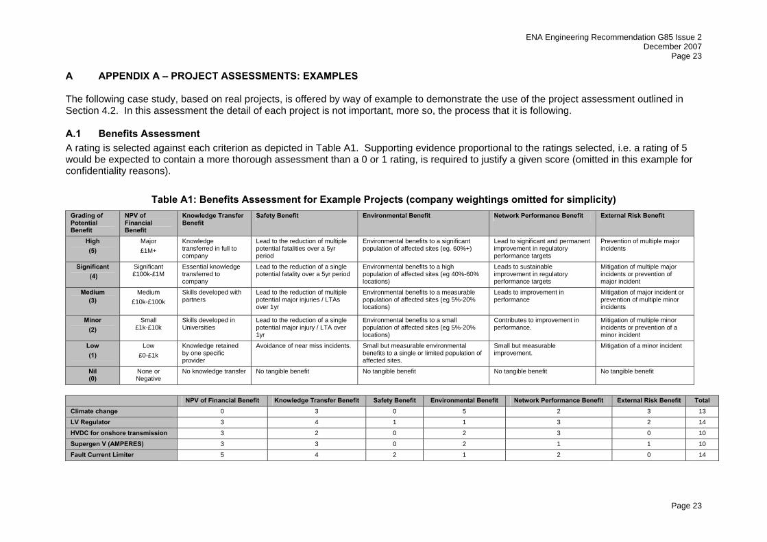
A APPENDIX A – PROJECT ASSESSMENTS: EXAMPLES The following case study, based on real projects, is offered by way of example to demonstrate the use of the project assessment outlined in Section 4.2. In this assessment the detail of each project is not important, more so, the process that it is following. A.1 Benefits Assessment A rating is selected against each criterion as depicted in Table A1. Supporting evidence proportional to the ratings selected, i.e. a rating of 5 would be expected to contain a more thorough assessment than a 0 or 1 rating, is required to justify a given score (omitted in this example for confidentiality reasons).
Table A1: Benefits Assessment for Example Projects (company weightings omitted for simplicity) Grading of Potential Benefit
NPV of Financial Benefit
Knowledge Transfer Benefit
Safety Benefit Environmental Benefit Network Performance Benefit External Risk Benefit
High (5)
Major £1M+
Knowledge transferred in full to company
Lead to the reduction of multiple potential fatalities over a 5yr period
Environmental benefits to a significant population of affected sites (eg. 60%+)
Lead to significant and permanent improvement in regulatory performance targets
Prevention of multiple major incidents
Significant (4)
Significant £100k-£1M
Essential knowledge transferred to company
Lead to the reduction of a single potential fatality over a 5yr period
Environmental benefits to a high population of affected sites (eg 40%-60% locations)
Leads to sustainable improvement in regulatory performance targets
Mitigation of multiple major incidents or prevention of major incident
Medium (3)
Medium £10k-£100k
Skills developed with partners
Lead to the reduction of multiple potential major injuries / LTAs over 1yr
Environmental benefits to a measurable population of affected sites (eg 5%-20% locations)
Leads to improvement in performance
Mitigation of major incident or prevention of multiple minor incidents
Minor (2)
Small £1k-£10k
Skills developed in Universities
Lead to the reduction of a single potential major injury / LTA over 1yr
Environmental benefits to a small population of affected sites (eg 5%-20% locations)
Contributes to improvement in performance.
Mitigation of multiple minor incidents or prevention of a minor incident
Low (1)
Low £0-£1k
Knowledge retained by one specific provider
Avoidance of near miss incidents. Small but measurable environmental benefits to a single or limited population of affected sites.
Small but measurable improvement.
Mitigation of a minor incident
Nil (0)
None or Negative
No knowledge transfer No tangible benefit No tangible benefit No tangible benefit No tangible benefit
NPV of Financial Benefit Knowledge Transfer Benefit Safety Benefit Environmental Benefit Network Performance Benefit External Risk Benefit Total Climate change 0 3 0 5 2 3 13
LV Regulator 3 4 1 1 3 2 14
HVDC for onshore transmission 3 2 0 2 3 0 10
Supergen V (AMPERES) 3 3 0 2 1 1 10
Fault Current Limiter 5 4 2 1 2 0 14

ENA Engineering Recommendation G85 Issue 2 December 2007 Page 24
24
The cumulative nature of the benefits can be seen in Figure A1. Without the application of company weightings, it can be seen that all categories have equal value in the assessment.
0
2
4
6
8
10
12
14
16
Climate change LV Regulator HVDC for onshore transmission Supergen V (AMPERES) Fault Current Limiter
Project
Rat
ing
NPV of Potential Financial Benefit Knowledge Transfer Benefit Safety Benefit
Environmental Benefit Network Performance Benefit External Risk Benefit
Figure A1: The Development of a Benefit Score from ratings in Table A1

ENA Engineering Recommendation G85 Issue 2 December 2007
Page 25
Page 25
A.2 Risk Assessment Project risks and the mitigation measures are assessed as per Table A2, over. As with the benefits assessment, justification is required alongside each assessment (again omitted in this example for confidentiality reasons).
-15
-10
-5
0
5
10
Climate change LV Regulator HVDC for onshore transmission Supergen V (AMPERES) Fault Current Limiter
Project
Miti
gatio
n M
easu
res
R
isks
Innovation Level (Technology Readiness) Development TypeAverage Annual Spend per Company Leverage (Collaboration Ratio)Likelihood of Implementation
Figure A2: Chart showing Project Risks and Mitigation Measures for each Project

ENA Engineering Recommendation G85 Issue 2 December 2007 Page 26
26
Table A2: Project Risk Assessment Risk Factors Mitigation Factors Innovation Level
(Technology Readiness)
Development Type Average Annual Spend (per company)
Leverage Collaboration Ratio
Likelihood of implementation
5 Research (Applied proof of concept)
Radical <£5k 0-20% 80-100%
4 Research (Applied analytical knowledge development
Significant £5k-10k 20-40% 60-80%
3 Development (Laboratory Experiments
Technological substitution from outside industry
£10k-25k 40-60% 40-60%
2 Development (Small scale trials / prototypes)
Technological substitution from different application
£25k-50k 60-80% 20-40%
1 Demonstration (System prototypes or trials)
Incremental £50k-80k 80-100% 0-20%
0 Existing None >£80k 100% 0%
Risk Mitigation Residual Climate change 4 2 -2 -5 -4 6 -11 -5 LV Regulator 2 2 0 -2 -5 4 -7 -3 HVDC for onshore transmission
4 2 0 0 -1 6 -1 5
Supergen V (Amperes)
4 3 -3 -5 -4 7 -12 -5
Fault Current Limiter
3 4 0 -4 -3 7 -7 0
Notes on ratings: Risks are set by the project type, therefore acting in a consistent manner
Mitigation: Spend is dependent on the quotation(s) received for a project Leverage is dependent on the number of partners and the level of their financial input Likelihood of implementation is dependent on a company’s ability to extract value from the project upon completion (this will vary between companies) Residual = Risk – Mitigation
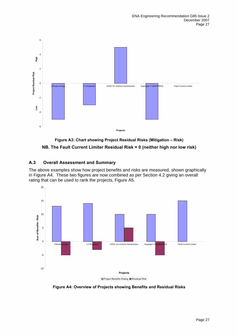
In line with Section 4.2, the risks and mitigation factors are combined to produce a residual risk figure. This is shown graphically in Figure A3 over, with a higher risk project having a positive resultant, and a lower risk project having a negative resultant risk figure.
ENA Engineering Recommendation G85 Issue 2 December 2007
Page 27
Page 27
-6
-4
-2
0
2
4
6
Climate change LV Regulator HVDC for onshore transmission Supergen V (AMPERES) Fault Current Limiter
Projects
Proj
ect R
esid
ual R
isk
Low
H
igh
Figure A3: Chart showing Project Residual Risks (Mitigation – Risk)
NB. The Fault Current Limiter Residual Risk = 0 (neither high nor low risk)
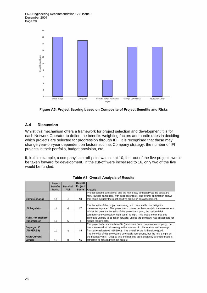
A.3 Overall Assessment and Summary The above examples show how project benefits and risks are measured, shown graphically in Figure A4. These two figures are now combined as per Section 4.2 giving an overall rating that can be used to rank the projects, Figure A5.
-10
-5
0
5
10
15
20
Climate change LV Regulator HVDC for onshore transmission Supergen V (AMPERES) Fault Current Limiter
Projects
Sum
of B
enef
its /
Ris
k
Project Benefits Rating Residual Risk Figure A4: Overview of Projects showing Benefits and Residual Risks
ENA Engineering Recommendation G85 Issue 2 December 2007 Page 28
28
0
2
4
6
8
10
12
14
16
18
20
Climate change LV Regulator HVDC for onshore transmission Supergen V (AMPERES) Fault Current Limiter
Project
Ove
rall
Pro
ject
Sco
re
Figure A5: Project Scoring based on Composite of Project Benefits and Risks
A.4 Discussion Whilst this mechanism offers a framework for project selection and development it is for each Network Operator to define the benefits weighting factors and hurdle rates in deciding which projects are selected for progression through IFI. It is recognised that these may change year-on-year dependent on factors such as Company strategy, the number of IFI projects in their portfolio, budget provision, etc. If, in this example, a company’s cut-off point was set at 10, four out of the five projects would be taken forward for development. If the cut-off were increased to 16, only two of the five would be funded.
Table A3: Overall Analysis of Results
Project Benefits Rating
Residual Risk
Overall Project Score Analysis
Climate change 13 -5 18
Project benefits are strong, and the risk is low (principally as the costs are fairly low per participant, with good leverage). The overall summation shows that this is actually the most positive project in this assessment.
LV Regulator 14 -3 17The benefits of the project are strong, with reasonable risk mitigation measures in place. This project also comes out favourably in the assessment.
HVDC for onshore transmission 10 5 5
Whilst the potential benefits of this project are good, the residual risk (predominantly a result of high costs) is high. This would mean that this project is unlikely to be taken forward, unless the company had an appetite for higher risk projects.
Supergen V (AMPERES) 10 -5 15
The project offers some benefits (this varies from company to company), but has a low residual risk (owing to the number of collaborators and leverage from external parties - EPSRC). The overall score is therefore good.
Fault Current Limiter 15 0 15
The benefits of thjs project are potentially very strong, but the risk is right on the boundary (nil). Despite this, the benefits are sufficiently strong to make it attractive to proceed with the project.

ENA Engineering Recommendation G85 Issue 2 December 2007
Page 29
Page 29
B APPENDIX B – REGISTERED POWER ZONES (RPZ)
B.1 Outline An RPZ is a zone of network where innovative practices that allow distributed generation to connect more easily are demonstrated. RPZs are intended to encourage DNOs to develop and demonstrate new, more cost effective ways of connecting and operating generation that will deliver specific benefits to new Distributed Generators (DG) and broader benefits to consumers generally. A DNO will receive additional income (over and above the main DPCR4 DG incentive) which will be recovered by the GDUoS. The DNO must demonstrate that an innovative solution could offer material advantages to DG customers compared to a conventional solution. Although an RPZ requires the connection of a new generator, RPZ are not restricted to green field sites. The RPZ may contain existing generators although only new generators will attract the RPZ premium. Where an RPZ is commissioned in stages, the DNO’s entitlement to the five-year period of the RPZ premium will be triggered by the commissioning date of each generating unit. The total MW of installed capacity can’t exceed the registered capacity. An individual generating unit forming part of staged development of an RPZ must be commissioned by 31 March 2012 to qualify for the RPZ premium. Each RPZ is defined as a collection of contiguously connected distribution system assets (i.e. which provide an electrical path for the distribution of electrical energy) having one or more terminal points which together describe in full the RPZ’s boundary with the total system. These terminal points will be selected such that any system components or connected customers (existing demand and generation) that may be affected by the RPZ project are included within them. The definition of an RPZ allows flexibility and will need to be applied differently depending on the project. For example if a number of small generators are involved it may be useful to define the limits of the RPZ in terms of geography as well as electrically as this will be a boundary that the stakeholders can identify. On the other hand if an RPZ involves for example the innovative connection of a wind farm in a remote area, defining the boundary in terms of a circuit may be sufficient. The boundary may need to be adjusted if new DG is connected on the edge of an RPZ, provided that it is judged appropriate to include the new DG in the demonstration of innovative practices.
B.2 RPZ Eligibility An RPZ must facilitate the connection of new DG. The DNO’s financial incentive for achieving RPZ registration is realised as an increase in its allowed revenue from GDUoS Charges. As the innovative practices are to be demonstrated on the network RPZ innovations should be already proven at least at a pilot scale. Demonstration within an RPZ should be the final stage of development before widespread adoption.
B.2.1 Demonstration of RPZ Innovation This innovation can be demonstrated in a RPZ through a number of ways:
o Equipment: The use of a piece of equipment of genuinely new design could alone constitute material innovation. This would not extend to the incremental development of existing technology. It may be appropriate for more than one RPZ to be justified in relation to a new piece of equipment if the specific application or duty of the equipment was sufficiently different.
ENA Engineering Recommendation G85 Issue 2 December 2007 Page 30
30
o System design/topology: An RPZ justification could be made for a novel approach to system design, in particular to increase the utilisation of assets. It is likely that innovation in system design would also require innovation in control and protection.
o System operation/control: Novel approaches to the operation and control of a distribution system (voltage, power flow, fault level) that facilitate the connection and operation of DG.
o Supply continuity and quality: The use of DG to enhance supply continuity and quality and/or offer a novel alternative to the use of traditional network reinforcement to meet licence standards.
B.2.2 Further Considerations There are a number of other issues that must be considered for a proposal to be eligible as an RPZ: Affected Customers: It is expected that in most cases existing demand and generation customers will be connected to the RPZ network. A DNO will be required to assess all potential impacts that the RPZ proposal could have on these customers. Where potential negative impacts are identified, these will be reported via the application for registration. Measures available to mitigate these potential negative impacts must also be identified. Q of S monitoring equipment might be required to demonstrate the commitment to protect customers’ interests. Materiality & Risk: The materiality of the innovation (in respect of its cost in particular) compared to that of the complete connection will be taken into account when justifying RPZ registration. The rationale supporting the RPZ premium is that it provides a return appropriate to the risk that the DNO is taking. The actual cost of the innovative component alone is not necessarily relevant in justifying RPZ registration. Ofgem will therefore require the DNO to identify the risks that it is managing (related specifically to the RPZ proposal) and its associated financial exposure. In a situation where there is doubt that the materiality of the innovation justifies the RPZ reward, this information can be used in support of the DNO’s case. Standards: The default option in relation to statutory standards (e.g. ESQC Regulations), regulatory standards (eg. IIP) and industry standards (e.g. standards as sited in Annex 1 of the Distribution Code) is that they apply in an RPZ exactly as they would elsewhere. If a relaxation of any standard is sought in connection with the RPZ, the DNO will be required to provide a justification for this. It will be at the sole discretion of the body that governs the standard to decide whether the requested relaxation should be granted. The impact on consumers of any such relaxation will be of paramount importance in the assessment of the case for a relaxation. The generator(s) directly involved in the innovation will have to be informed of the RPZ proposal and any technical and commercial impacts it might have compared with the extant connection option as part of the negotiation of a connection agreement. Ofgem may seek advice from an independent expert panel as to whether proposed projects have appropriate innovation content and are technically credible. The panel will not form a view as to the probability of success of the project.

ENA Engineering Recommendation G85 Issue 2 December 2007
Page 31
Page 31
B.3 Example: Projects that could be considered for RPZs
B.3.1 Business parks Where generation (and potentially district heating/cooling) could be integrated with network design to offer lower connection costs for a given level of security than would otherwise be the case. This could involve using innovative equipment, system design and topology and improve system continuity/quality.
B.3.2 Social housing schemes Where CHP could be integrated with network design to reduce connection costs. This could involve innovative system design and topology.
B.3.3 Reception networks Where using innovative equipment or practices, the system would be optimised to accept energy from a number of adjacent generators, and there would be a degree of financial risk upon distributors through investing in advance of firm connection requests (that is, no single generator could afford the full infrastructure, but it could be facilitated through advance investment for the connection of the group, each bearing their fair share after connection). This could involve innovative equipment, system design and topology, and system operation and control.
B.3.4 Innovation and Benefit assessment for an RPZ To register an RPZ it must be demonstrated to Ofgem that the project will allow a more cost effective DG connection when compared to a conventional connection solution. This comparison should take into account cost, risk to the quality of supply and how easily the innovation could be reapplied across the network. The assessment requirements for registration are outlined in section 0. If new DG is not connected then the DNO will not receive the RPZ incentive premium that it is allowed in return for the increase in investment and risk The business case and the fit of a project with the overall strategy of the DNO should be evaluated as for any other project. For an RPZ the gains will most likely be in terms of finance and quality of supply. It should be emphasised that the benefits may come over a relatively long period. Studies into innovation on the electricity network have shown typical time scales for potential savings range from 3-12 years.
B.4 RPZ Registration All RPZs must be registered with Ofgem and to ensure a fair evaluation it will be essential that all applications are considered against consistent criteria. To assist this process a proforma application form is available on the Ofgem web site (www.ofgem.gov.uk). Application will be accepted at any time from the 1st April 2005 to 31st March 2010. An example application is shown under Annex 8 to this GPG.
B4.1 Application timescale DNOs will be able to apply for RPZ registration from 1 April 2005 to 31 March 2010. A connection project will have to be commissioned (defined as becoming commercially available under a connection agreement) between 1 April 2005 and 31 March 2012 to qualify for the RPZ premium.

ENA Engineering Recommendation G85 Issue 2 December 2007 Page 32
32
Norm
ally 15 days
Submission to Ofgem.
Submission accepted. Application date
registered as the date of acceptance.
Ofgem considers application against published criteria.
Registration granted.
Registration not granted. Assessment made
available to applicant.
Application complete?
Application accepted?
Advice from independent
panel required.
Application revised.
Application accepted?
Advice received from independent panel.
Norm
ally 15 days
Registration granted.
10 days
Figure B1: Diagram of the RPZ Registration Process
The Registration process is described in the flow diagram in Figure B1 and will comprise the following steps:
B.4.2 DNO submission of application to Ofgem Ofgem acknowledges the application within 10 working days and advises applicant if the application is complete and therefore valid. If it is complete the application date is registered as the date of acceptance by Ofgem. If it is not, the application is deemed void until its identified deficiencies are addressed to Ofgem’s satisfaction. Ofgem will then confirm the application date.
B.4.3 Ofgem’s consideration of applications Ofgem will consider each application against published assessment criteria. Where an application is rejected, Ofgem’s assessment will be made available to the applicant. Ofgem’s assessment will normally be completed in 15 working days. However, if Ofgem considers that the advice of the independent panel is required the applicant will be informed and a further 15 working days will be allowed.
For those projects that are granted RPZ registration, there will be a duty placed on the registrant to inform Ofgem of any change to the RPZ proposal after registration. Ofgem will reserve the right to withdraw registration if in its sole judgement changes made to an RPZ cause the registration criteria to no longer be met.

ENA Engineering Recommendation G85 Issue 2 December 2007
Page 33
Page 33
B.5 Ongoing Regulatory Reporting Requirements for RPZ Ofgem will require an annual report of the status of each DNO’s RPZ projects (i.e. by no later than the 31 July immediately following the end of the reporting year as required by the RIGs). This report will cover all committed and operational projects but should ideally also include details of RPZ registrations that are planned for the period up to 31 March following publication of the annual report.
Ofgem expects to publish the RIGs at least one month in advance of the relevant reporting year, normally in February. As with IFI projects Ofgem will also provide the DNOs with standard templates that should be used for the reporting of relevant information. Any changes to the RIGs will have been consulted on for a period of time in accordance with the paragraphs 9 to 11 of SLC 51. Where these changes do not relate to information included in the incentive scheme or the required level of accuracy the consultation period will not be less than 28 days.
DNOs will normally be required to provide the following information for each relevant RPZs at the end of the reporting year and by no later than the immediately following 30 June. In terms of capacity the reporting must be to an accuracy of at least 0.1MW. The reporting requires the following information:
A schedule of all RPZ projects planned, committed, under construction and operational detailing their starting year.
• Incentivised distributed generating capacity in MW. • Connection cost • Summary of the innovation content of the RPZ • The justification for each RPZ project/ the potential benefit to customer and DG that it
is expected to deliver. • Whether the benefits reported are consistent with those stated in the RPZ
application.
A DNO will be obliged to provide details of the technical operation of the RPZ, subject to any confidentiality constraints, to bona fide third parties on request. Sharing of good practice and the avoidance of duplication should be priorities. For operating RPZs, a report of the performance achieved in the reporting year will be submitted in a form agreed with Ofgem.
Ofgem could undertake an audit of the information over the course of the subsequent months following the submission.
Reports to Ofgem will be made publicly available. These reports will be published on the Ofgem website. If there is information required by Ofgem that the DNO or its collaborators considers commercially sensitive, they will request that this information is not published. Ofgem considers that the level of detail of reporting is such that it will be rare that the reports will not be published.
B.6 Report Formats The typical form for end of year reporting provided by Ofgem requires:
• the name of each RPZ • its DG capacity in MW • its starting year

ENA Engineering Recommendation G85 Issue 2 December 2007 Page 34
34
In addition, the information in the table below will give Ofgem sufficient visibility of a programme of projects. Ofgem may then require further information on particular projects.
Table B4: RPZ Reporting Template
Description of project and technical details
Expenditure for financial year
Type(s) of innovation involved
Status (planned, under construction, operational) and operational starting year
Connection cost Benefit to customers compared to those envisage when project was registered
B.7 RPZ Example Application A shopping and leisure centre is to be built on a brown field site. As the site will be used for most of the day and there will be a swimming pool and large refrigerators that consume large amounts of heat the development is ideal for installing a CHP plant. However there are times of day when the heat requirements and power requirements are not balanced and therefore the site is grid connected and at times exports power. The fault level on the surrounding network would be increased beyond its rated value if the generator is connected. The area is an urban environment where grid reinforcement will be expensive and difficult. It is therefore proposed to implement a system of sequential switching of protection. The proposed system will be designed so that if a fault occurs on part of the adjacent network, the circuit breaker on the CHP unit is opened before any other breaker so the ratings of the existing breakers are not exceeded (as detailed in the DTI’s Basic Active Management report). Once the fault has been cleared the CHP unit can be reconnected. UPS will need to be installed on vital loads as a matter of course and these will be used to ensure that the loads are supplied even if the generator is tripped off. The impact for the shopping/leisure centre will be small as the CHP unit can be run as a heat only unit so that the heat loads will not be affected. In addition, if necessary the CHP unit can be run at a constrained level so that it just supplies the site demand.

ENA Engineering Recommendation G85 Issue 2 December 2007
Page 35
Page 35
B.7.1 Example RPZ Documentation
RPZ Summary It is planned to install a biomass CHP unit in a new shopping and leisure centre. A system of sequential switching will be used to prevent the ratings of existing protection being exceeded. This will provide a low cost connection solution in an urban area where the alternative of grid reinforcement is difficult and expensive. The fault contribution and hence the size of generator that can be connected is larger than would be possible without sequential switching. In return the generator is disconnected during a fault and once the fault is cleared the generator may need to be constrained if the capacity of the network is reduced. The UPS systems on vital loads ensure that they continue to be supplied. The impact for the shopping/leisure centre will be small as the CHP unit can be run as a heat only unit so that the heat loads will not be affected. In addition, if necessary the CHP unit can be run at a constrained level so that it just supplies the site demand. Sequential switching of this type has the potential to be used in a number of sties across the UK to enable connection of DG at an affordable price. Generation Details Location
Shopfunsite, Anytown, Someshire. 11kV feeder from Anytown _suberb to Shopfunsite
Type Biomass CHP unit, synchronous generator
Capacity
2 MVA maximum export 1.8 MW, 0.03 MVAr
Connection voltage 11kV
Commissioning date 5th June 2005 Licence status
Connection standards applicable Grid code, D code, G59/1 Required connection date 31st August 2005
Generator Involvement
Generator informed (Yes / No)
Yes
Generator Supportive (Yes / No)
Yes. See attached document ABC.123
Generator Agreement
The generator will be disconnected if there is fault on the adjacent network. If it cannot be reconnected quickly, it may run constrained to supply the site load only. This is laid out in the connection agreement. The cost of the protection and switches used solely by the generator will be met through the initial connect charge as will costs that are not eligible for the GDUoS. The developers of the site have been closely involved with the connection design to ensure that the generation and on-site load are compatible with the protection system.

ENA Engineering Recommendation G85 Issue 2 December 2007 Page 36
36
Existing generators will experience longer protection clearance times and have been consulted. It does not breach their connection agreements. The consultation will be followed up by verifying with the manufacturers that the longer clearance times do not cause a problem. The generator accepts the additional risk that if it sequential switching does not operate correctly it will be disconnected until the problem is solved. This will result in loss of revenue however the DNO will also not be able to collect the GDUoS. The DNO takes on the increased risk of potential damage to the network if sequential switching does not operate correctly.
Generator name and contact details
Universal Generator co. ltd. 123 Main street, Bigtown
Conventional and RPZ options Description of conventional connection solution
Reinforce the grid and replace protection and switchgear for all the load and generation connected to the 11kV busbar. The upgrade will cost in the region of £600, 000 with considerable extra cost due to the downtime for the work to be done. Overall the cost will be in the region of £700,000. The time required to implement the upgrade would be approximately 2 to 3 weeks of downtime including time for testing A separate connection is not possible because of constraints of the urban environment.
Description of RPZ solution
A network diagram is attached to this form. An example of how the sequential switching will work is illustrated above. Instead of reinforcing the network and replacing the protection sequential switching is used. Three separate components can be seen to contribute to the fault current; Transformer 1, Transformer 2 and the Generator. Ordinarily, the protection would be arranged such that Circuit Breaker 5 would clear the fault directly. However, the additional fault contribution introduced the generator results in the fault current flowing through Circuit Breaker 5 exceeding its rating. The operation of Circuit Breaker 5 is inhibited until either Circuit Breaker 1, Circuit Breaker 2, Circuit Breaker 3 or Circuit Breaker 6 is operated. RPZ terminal points: transformer 1 and 2 and the loads and generators connected to the 11kV busbar.

ENA Engineering Recommendation G85 Issue 2 December 2007
Page 37
Page 37
Cost: The cost including installation and the cost of the downtime of the network will be approximately £140 000. The time to implement the scheme will be approximately 2-3 days. Compared to a conventional solution savings are made in materials, work required and downtime.
Repeatability
The work could be replicated in most urban areas in the UK.
Risks Technical Risks
There is a risk that the longer clearance times experienced by the other generators on the busbar could cause stability problems causing more generation to be tripped off. This could put further strain on supply and potentially cause cascade tripping. Discussions with owners and manufactures will be carried out to check that the generators can operate with the longer clearance times. There is a safety risk if the sequential switching mal-operates. The operation of back-up protection will be check to ensure that it will operate before serious damage is caused if the sequential-switching fails.
Customer Risks (Demand & generation)
There is a risk that the longer clearance times experienced by the other generators on the busbar could cause stability problems causing more generation to be tripped off. This could have financial consequences for the DNO if it causes a breach of a connection agreement. Discussions with owners and manufactures will be carried out to check that the generators can operate with the longer clearance times.
Statutory & Regulatory Standards
The proposed RPZ will fulfil all statutory and regulatory standards.
0.014MW 0.113MW 0.12MW 0.25MW 0.1MW 0.15MW 0.11MW 1.8MW 0.005MVAr 0.004MVAr 0.01MVAr 0.02MVAr 0.00MVAr 0.005MVAr 0.005MVAr 0.03MVAr