
en543050.pdf
55
1 © 2007 Microchip Technology Incorporated. All Rights Reserved. WebSe minar Title Slide 1 Introduction to Stepper Motors Part 2: Stepper Motor Control My name is Marc McComb, I am a Technical Training Engineer here in Microchip’s Securit y, Microcont roller and Technology Division. Welcom e to Part 2 in t he “ Introduct ion to Stepp er Motors” series of Web Sem inars, “ Stepp er Motor Control”
-
Upload
gsudhanta1604 -
Category
Documents
-
view
218 -
download
0
Transcript of en543050.pdf

7/28/2019 en543050.pdf
http://slidepdf.com/reader/full/en543050pdf 1/55
© 2007 Microchip Technology Incorporated. All Rights Reserved. WebSeminar Title Slide 1
Introduction to Stepper Motors
Part 2: Stepper Motor Control
My name is Marc McComb, I am a Technical Training Engineer here in Microchip’sSecurity, Microcontroller and Technology Division. Welcome to Part 2 in the“Introduction to Stepper Motors”series of Web Seminars, “Stepper Motor Control”

7/28/2019 en543050.pdf
http://slidepdf.com/reader/full/en543050pdf 2/55
© 2007 Microchip Technology Incorporated. All Rights Reserved. WebSeminar Title Slide 2
Agenda
z In this WebSeminar we will discuss:
− Different algorithms to step the motor
− Anti-resonance and its implications
− Drive Circui ts
In the following webseminar we will expand on Part 1 by discussing differentstepping algorithms to improve step resolutions. We will also discuss anti-resonanceand how to deal with it. Finally, we will look at some basic circuitry to interface astepper motor to a microcontroller.
7/28/2019 en543050.pdf
http://slidepdf.com/reader/full/en543050pdf 3/55
© 2007 Microchip Technology Incorporated. All Rights Reserved. WebSeminar Title Slide 3
Stepping the Motor
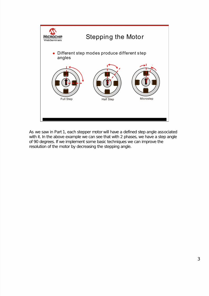
z Different step modes produce dif ferent s tepangles
Full Step Half Step Microstep
As we saw in Part 1, each stepper motor will have a defined step angle associatedwith it. In the above example we can see that with 2 phases, we have a step angleof 90 degrees. If we implement some basic techniques we can improve theresolution of the motor by decreasing the stepping angle.

7/28/2019 en543050.pdf
http://slidepdf.com/reader/full/en543050pdf 4/55
© 2007 Microchip Technology Incorporated. All Rights Reserved. WebSeminar Title Slide 4
Bipolar Full Step Control
N
S
PORTB
Winding A
W i n d i n g B
B’0B0Winding B
0 A’0 AWinding A
4321Step
A
B
A’
B’
Used in
Motor Drive
Motor
Drive
PIC®
Microcontroller
RB2
RB3
RB4
RB5
RB0
RB1
RB6
RB7
First, let’s discuss full stepping. Here the rotor is rotated at its specified step angleresolution. In the above diagram, two windings are connected to a motor drivecircuit which we will specify as a black box at this point. Later in this presentation wewill look inside this black box. For now though we will concentrate on the motorwindings and the PIC®Microcontroller. Notice that we are using a simple General
Purpose Input/Output Port peripheral here PORTB as an example. We will focusour attention to the top 4 Most Significant Bits in PORTB for the time being as theLower 4-bits are used in the Motor Drive “Black Box”Circuit. We will use thenomenclature throughout this presentation by defining each lead of each winding asfollows: Winding A leads will be identified by leads A and A’, while winding B leadswill be identified by leads B and B’. At the top Left-Hand corner of the diagram is ourstepping algorithm. Let’s step through this algorithm.

7/28/2019 en543050.pdf
http://slidepdf.com/reader/full/en543050pdf 5/55
© 2007 Microchip Technology Incorporated. All Rights Reserved. WebSeminar Title Slide 5
0001
Bipolar Full Step Control
N
S
0
0
01
PORTB
Winding AWinding A
W i n d i n g B
N S
current
B’0B0Winding B
0 A’0 AWinding A
4321Step
A
B
A’
B’Motor
Drive
PIC®
Microcontroller
RB2
RB3
RB4
RB5
RB0
RB1
RB6
RB7
The first step applies a positive voltage or logic HIGH to Winding A’s lead A whiledriving lead A’ LOW. Current is generated in the direction shown creating amagnetic flux polarizing the stator poles accordingly. The rotor rotates to minimizethe magnetic flux flow reluctance.

7/28/2019 en543050.pdf
http://slidepdf.com/reader/full/en543050pdf 6/55
© 2007 Microchip Technology Incorporated. All Rights Reserved. WebSeminar Title Slide 6
0010
Bipolar Full Step Control
N
S
0
0
10
PORTB
Winding A
W i n d i n g B
W i n d i n g B
N S
c ur r en t
N
S
B’0B0Winding B
0 A’0 AWinding A
4321Step
A
B
A’
B’Motor
Drive
PIC®
Microcontroller
RB2
RB3
RB4
RB5
RB0
RB1
RB6
RB7
The next step removes the applied voltage to Winding A and drives lead B HIGHinitiating current flow towards lead B’ which is driven LOW. Again the rotor rotatesminimizing the reluctance. Notice that as we step through this full step algorithm weare simply shifting a set bit right each time. Remember though, you will need toconnect the motor lead to the appropriate pins to accommodate this algorithm.

7/28/2019 en543050.pdf
http://slidepdf.com/reader/full/en543050pdf 7/55
© 2007 Microchip Technology Incorporated. All Rights Reserved. WebSeminar Title Slide 7
0100
Bipolar Full Step Control
N
S
0
1
00
PORTB
Winding AWinding A
W i n d i n g B
N S
current
N
S
N S
B’0B0Winding B
0 A’0 AWinding A
4321Step
A
B
A’
B’Motor
Drive
PIC®
Microcontroller
RB2
RB3
RB4
RB5
RB0
RB1
RB6
RB7
Continuing through the algorithm, lead A’ is next driven HIGH

7/28/2019 en543050.pdf
http://slidepdf.com/reader/full/en543050pdf 8/55
© 2007 Microchip Technology Incorporated. All Rights Reserved. WebSeminar Title Slide 8
1000
Bipolar Full Step Control
N
S
1
0
00
PORTB
Winding A
W i n d i n g B c ur r en t
B’0B0Winding B
0 A’0 AWinding A
4321Step
A
B
A’
B’Motor
Drive
PIC®
Microcontroller
RB2
RB3
RB4
RB5
RB0
RB1
RB6
RB7
Followed finally by driving lead B’ HIGH to complete the 360 degree rotation.

7/28/2019 en543050.pdf
http://slidepdf.com/reader/full/en543050pdf 9/55
© 2007 Microchip Technology Incorporated. All Rights Reserved. WebSeminar Title Slide 9
Full Step “ One Phase On” Voltage
Sequence
z Termed “Wave Drive” or “ One Phase On Control
A
B
STEP 1 STEP 2 STEP 3 STEP 4 STEP 1
A’
B’
This type of full step algorithm is referred to as One Phase On Voltage sequence. The term “Wave Drive”is sometimes used as the voltage sequence resembles awave. Each lead is energized one at time for each step.

7/28/2019 en543050.pdf
http://slidepdf.com/reader/full/en543050pdf 10/55
© 2007 Microchip Technology Incorporated. All Rights Reserved. WebSeminar Title Slide 10
Determining Speed
z Number of Steps per Revolut ion
= 360°/Angle for one step
Example
360°/90° = 4 steps/revolution
z Number of Pulses Per Second (PPS)=[ (Desired RPM) / 60 seconds] x Number of Steps/revoluti on
Example
[(120 RPM)/60 seconds] x (4 steps/revolut ion) = 8 pulses/second
Let’s take a moment and talk about speed of revolution or RPM. We can determinehow fast to apply the individual steps by following a few simple equations. First weneed to determine how many steps actually make up a complete 360degreerevolution. In this case, since we have a 90 degree step angle for each individualstep, we can say that it will take four steps for a complete revolution. Next, we need
to know how many pulses or steps we will apply per second to achieve the desiredrevolution. Therefore, we divide our desired RPM by 60 seconds and then multiplythe quotient by the number of steps in a complete revolution. The product providesus with the number of steps required per second to obtain the desired RPM.

7/28/2019 en543050.pdf
http://slidepdf.com/reader/full/en543050pdf 11/55
© 2007 Microchip Technology Incorporated. All Rights Reserved. WebSeminar Title Slide 11
Timing
z Timer0 to t ime PPS−
Pulse applied each time TMR0 interrupt occurs−
Must load TMR0 with a predetermined value
N
S
Winding A
W i n d i n g B
A
B
A’
B’
Timer0
Motor
Drive
PIC®
Microcontroller
RB2
RB3
RB4
RB5
RB0
RB1
RB6
RB7
We can easily implement the steps per second using Timer0 interrupts. We mustfirst configure the Timer0 prescaler accordingly and then load a pre-calculated valueinto the TMR0 register that will interrupt the CPU at the appropriate time intervals toperform subsequent steps.

7/28/2019 en543050.pdf
http://slidepdf.com/reader/full/en543050pdf 12/55
© 2007 Microchip Technology Incorporated. All Rights Reserved. WebSeminar Title Slide 12
Full Step “ One Phase On”
Algorithm
Increment counter variable
counter = 4?
Output step (counter) to
PORTB
TMR0 Interrupt
Initialize Peripherals
•Set PORTB direction
•Initialize PORTB
•Enable TMR0 interrupts
•load TMR0 value•Create 8-bit variable counter = 0
Define step values:•STEP_ONE = 1000xxxx
•STEP_TWO = 0100xxxx
•STEP_THREE = 0010xxxx
•STEP_FOUR = 0001xxxx
Loop
Main routine
return
YES Clear counter
NO
Referring to the above flow chart, to implement this in software, we must firstinitialize the two peripherals PORTB and Timer0 as discussed. We must also definevalues to pass to the PORTB register that will produce the desired output sequenceas well as define a counter variable. Following peripheral initialization and variabledefinitions, we simply place the CPU into a loop. On a Timer0 interrupt the counter
variable is incremented, checked and then used to determine which step value isoutputted to the PORTB register. Remember, if code development is done in C, thecounter variable will need to be declared as a global variable.

7/28/2019 en543050.pdf
http://slidepdf.com/reader/full/en543050pdf 13/55
© 2007 Microchip Technology Incorporated. All Rights Reserved. WebSeminar Title Slide 13
0000
Full Step “ Two Phase On” Bipolar
Control
N S
PORTB
Winding A
W i n d i n g B
B’B’BBWinding B
A A’ A’ AWinding A
4321Step
A
B
A’
B’Motor
Drive
PIC®
Microcontroller
RB2
RB3
RB4
RB5
RB0
RB1
RB6
RB7
The next full step algorithm is the Two Phase ON Bipolar control sequence. In thisalgorithm, two phases are energized simultaneously to rotate the rotor. Again, in ourdiagram the individual lead of Windings A and B are connected to the same “BlackBox”motor drive circuit which is connected to PORTB. Note that now our steppingalgorithm shown in the upper left corner of the slide has changed from the One
Phase On algorithm we have just discussed.
7/28/2019 en543050.pdf
http://slidepdf.com/reader/full/en543050pdf 14/55
© 2007 Microchip Technology Incorporated. All Rights Reserved. WebSeminar Title Slide 14
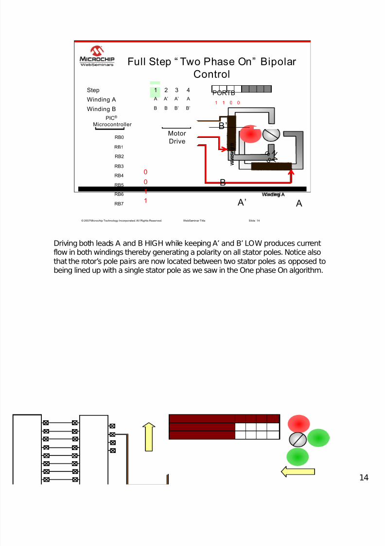
0011
Full Step “ Two Phase On” Bipolar
Control
N S
0
0
11
PORTB
Winding AWinding A
W i n d i n g B
W i n d i n g B
current
c ur r en t
B’B’BBWinding B
A A’ A’ AWinding A
4321Step
N S
A
B
A’
B’Motor
Drive
PIC®
Microcontroller
RB2
RB3
RB4
RB5
RB0
RB1
RB6
RB7
Driving both leads A and B HIGH while keeping A’ and B’ LOW produces currentflow in both windings thereby generating a polarity on all stator poles. Notice alsothat the rotor’s pole pairs are now located between two stator poles as opposed tobeing lined up with a single stator pole as we saw in the One phase On algorithm.

7/28/2019 en543050.pdf
http://slidepdf.com/reader/full/en543050pdf 15/55
© 2007 Microchip Technology Incorporated. All Rights Reserved. WebSeminar Title Slide 15
0110
Full Step “ Two Phase On” Bipolar
Control
N
S
0
1
10
PORTB
Winding AWinding A
W i n d i n g B
W i n d i n g B c ur r en t
current
B’B’BBWinding B
A A’ A’ AWinding A
4321Step
N S
N
S
A
B
A’
B’Motor
Drive
PIC®
Microcontroller
RB2
RB3
RB4
RB5
RB0
RB1
RB6
RB7
The next step in the algorithm maintains the current flow direction in Winding Bwhile reversing the current direction in Winding A. This causes the rotor rotate 90degrees so that it lies between the next two stator poles.

7/28/2019 en543050.pdf
http://slidepdf.com/reader/full/en543050pdf 16/55
© 2007 Microchip Technology Incorporated. All Rights Reserved. WebSeminar Title Slide 16
1100
Full Step “ Two Phase On” Bipolar
Control
N
S
1
1
00
PORTB
Winding AWinding A
W i n d i n g B
W i n d i n g B c ur r en t
current
B’B’BBWinding B
A A’ A’ AWinding A
4321Step
N S
N
S N
S
A
B
A’
B’Motor
Drive
PIC®
Microcontroller
RB2
RB3
RB4
RB5
RB0
RB1
RB6
RB7
As we continue through the algorithm, current direction through winding A ismaintained from the previous step while this time current direction is changed inWinding B.

7/28/2019 en543050.pdf
http://slidepdf.com/reader/full/en543050pdf 17/55
© 2007 Microchip Technology Incorporated. All Rights Reserved. WebSeminar Title Slide 17
1001
Full Step “ Two Phase On” Bipolar
Control
N
S
1
0
01
PORTB
Winding AWinding A
W i n d i n g B
W i n d i n g B
current
c ur r en t
B’B’BBWinding B
A A’ A’ AWinding A
4321Step
N S
N
S N
S
N
S
A
B
A’
B’Motor
Drive
PIC®
Microcontroller
RB2
RB3
RB4
RB5
RB0
RB1
RB6
RB7
The final step rotates the rotor to its starting position.

7/28/2019 en543050.pdf
http://slidepdf.com/reader/full/en543050pdf 18/55
© 2007 Microchip Technology Incorporated. All Rights Reserved. WebSeminar Title Slide 18
Full Step “ Two Phase On” Voltage
Sequence
A
B
STEP 1 STEP 2 STEP 3 STEP 4 STEP 1
A’
B’
If we look at the voltage sequence for the Two Phase On algorithm we can clearlysee that at any given time current is flowing it both windings.

7/28/2019 en543050.pdf
http://slidepdf.com/reader/full/en543050pdf 19/55
© 2007 Microchip Technology Incorporated. All Rights Reserved. WebSeminar Title Slide 19
Full Step “Two Phase On”
Algorithm
Increment counter variable
counter = 4?
Output step (counter) to
PORTB
TMR0 Interrupt
Initialize Peripherals
•Set PORTB direction
•Initialize PORTB
•Enable TMR0 interrupts
•load TMR0 value•Create 8-bit variable counter = 0
Define step values:•STEP_ONE = 1100xxxx
•STEP_TWO = 0110xxxx
•STEP_THREE = 0011xxxx
•STEP_FOUR = 1001xxxx
Loop
Main routine
return
YES Clear counter
NO
So how does this change our software algorithm? Apart from redefining the stepvalues the rest of the flowchart remains unchanged.

7/28/2019 en543050.pdf
http://slidepdf.com/reader/full/en543050pdf 20/55
© 2007 Microchip Technology Incorporated. All Rights Reserved. WebSeminar Title Slide 20
Anti-resonance
Now that we have looked at both full step algorithms, we need to introduce acondition known as anti-resonance

7/28/2019 en543050.pdf
http://slidepdf.com/reader/full/en543050pdf 21/55
© 2007 Microchip Technology Incorporated. All Rights Reserved. WebSeminar Title Slide 21
Anti-resonance
z Every Stepper Motor has a natural anti-resonantfrequency
− Increase in audible motor no ise
− Increase in motor vibration
z Anti -resonant point wil l vary
− With application and load
z Typically at low speeds
− 100 – 200pps
z Severe cases may cause motor to miss steps
Every stepper motor will have anti-resonant points typically centered around thestepper motor’s resonant frequency. Resonance actually helps rotate the rotor, anti-resonance on the other hand impedes it. Anti-resonant points typically occur atlower speed but are mostly dependant on the application and load on the rotor itself.Anti-resonant points are characterized by increased motor vibration along with
audible motor noise. As we will see, in severe cases anti-resonance will interferewith rotor rotation to such an extreme that some steps in the full step algorithm willactually be missed.

7/28/2019 en543050.pdf
http://slidepdf.com/reader/full/en543050pdf 22/55
© 2007 Microchip Technology Incorporated. All Rights Reserved. WebSeminar Title Slide 22
Anti-resonance
z Moving in large steps could causeovershoots and ringing
NN
SS
90°
180°
Time
A n g l e o f R o t a t i o n
Looking at the above diagram, on the left is a simple permanent magnet motor. Onthe right, a graph that will be used to represent angular rotation of the rotor.

7/28/2019 en543050.pdf
http://slidepdf.com/reader/full/en543050pdf 23/55
© 2007 Microchip Technology Incorporated. All Rights Reserved. WebSeminar Title Slide 23
Anti-resonance
z Moving in large steps could causeovershoots and ringing
NN S S
90°
180°
Time
A n g l e o f R o t a t i o n
Ringing
When a step is executed the rotor shaft will undergo a period of time where aringing occurs before finally settling at the energized stator pole pair.

7/28/2019 en543050.pdf
http://slidepdf.com/reader/full/en543050pdf 24/55
© 2007 Microchip Technology Incorporated. All Rights Reserved. WebSeminar Title Slide 24
Anti-resonance
z Moving in large steps could causeovershoots and ringing
N N
S S 90°
180°
Time
A n g l e o f R o t a t i o n
Ringing
P u l s e
P u l s e
Subsequent steps will suffer from this same ringing.

7/28/2019 en543050.pdf
http://slidepdf.com/reader/full/en543050pdf 25/55
© 2007 Microchip Technology Incorporated. All Rights Reserved. WebSeminar Title Slide 25
Anti-resonance
z Missed steps could occur if step time
coincides with oscillations
90°
180°
Time
A n g l e o f R o t a t i o n
P u l s e
In severe cases, this ringing could be so pronounced that the rotor will not have timeto settle before the next step pulse is applied.

7/28/2019 en543050.pdf
http://slidepdf.com/reader/full/en543050pdf 26/55
© 2007 Microchip Technology Incorporated. All Rights Reserved. WebSeminar Title Slide 26
Anti-resonance
z Missed steps could occur if step time
coincides with oscillations
90°
180°
Time
A n g l e o f R o t a t i o n
P u l s e P u l
s e
N N
S S
In the above example, the excessive ringing has caused the motor rotation to missthe first step at 90 degrees. In position sensitive applications this could have severeconsequences. Not to mention that if you are not using a feedback network of anykind, rotor position will be undetermined.

7/28/2019 en543050.pdf
http://slidepdf.com/reader/full/en543050pdf 27/55
© 2007 Microchip Technology Incorporated. All Rights Reserved. WebSeminar Title Slide 27
Half Stepping
We can overcome anti-resonance in a couple of ways. Here we offer a change tothe stepping algorithm as a solution.

7/28/2019 en543050.pdf
http://slidepdf.com/reader/full/en543050pdf 28/55
© 2007 Microchip Technology Incorporated. All Rights Reserved. WebSeminar Title Slide 28
Half Stepping
z Combines “ One Phase On” and “ TwoPhase On” algorithms
z Improves rotational resolution
z Minimizes anti-resonance
Half-stepping is a method of combining both One Phase On and Two Phase On fullstep algorithms. In doing so, the step angle is essentially halved. For example our90 degree per step motor we have been using, will have a new step angle of 45degrees when using half stepping. Since the rotor shaft doesn’t have as far to travelfrom one step to the other, the ringing produced at each step is minimized thereby
reduce the anti-resonant effects exhibited using full step algorithms.

7/28/2019 en543050.pdf
http://slidepdf.com/reader/full/en543050pdf 29/55
© 2007 Microchip Technology Incorporated. All Rights Reserved. WebSeminar Title Slide 29
0000
Bipolar Half Step Control
N
S
0
0
00
PORTB
Winding A
W i n d i n g B
B A’
4
0 A’
5
B’ A’
6
B’0
7
B’BB0Winding B A0 A AWinding A
8321Step
A
B
A’
B’Motor
Drive
PIC®
Microcontroller
RB2
RB3
RB4
RB5
RB0
RB1
RB6
RB7
Let’s take a look at how half-stepping is accomplished. Again, no change to ourblock diagram. However, notice that the step algorithm is now twice as long as infull-step examples. This makes sense considering that if we reduce the step angleby half…it will take twice as many steps to complete a 360 degree rotation.

7/28/2019 en543050.pdf
http://slidepdf.com/reader/full/en543050pdf 30/55
© 2007 Microchip Technology Incorporated. All Rights Reserved. WebSeminar Title Slide 30
0001
Bipolar Half Step Control
0
0
01
PORTB
Winding AWinding A
W i n d i n g B
current
B A’
4
0 A’
5
B’ A’
6
B’0
7
B’BB0Winding B A0 A AWinding A
8321Step
A
B
A’
B’
N S
Motor
Drive
PIC®
Microcontroller
RB2
RB3
RB4
RB5
RB0
RB1
RB6
RB7
The first step in this new algorithm is actually the first step of the One Phase Onalgorithm we discussed. Current flow occurs in winding A only and the rotorresponds by rotating to align its pole pairs with the stator poles.

7/28/2019 en543050.pdf
http://slidepdf.com/reader/full/en543050pdf 31/55
© 2007 Microchip Technology Incorporated. All Rights Reserved. WebSeminar Title Slide 31
0011
Bipolar Half Step Control
N S
0
0
11
PORTB
Winding AWinding A
W i n d i n g B
W i n d i n g B
current
c ur r en t
B A’
4
0 A’
5
B’ A’
6
B’0
7
B’BB0Winding B A0 A AWinding A
8321Step
A
B
A’
B’Motor
Drive
PIC®
Microcontroller
RB2
RB3
RB4
RB5
RB0
RB1
RB6
RB7
Next, the first step in the Two Phase On full-step algorithm is implemented. Currentis maintained in winding A from the previous step only this time winding B isenergized to produce current flow. Now the rotor, in the attempt to reduce thereluctance from the two Magnetic Flux produced, positions itself between statorpoles.

7/28/2019 en543050.pdf
http://slidepdf.com/reader/full/en543050pdf 32/55
© 2007 Microchip Technology Incorporated. All Rights Reserved. WebSeminar Title Slide 32
0010
Bipolar Half Step Control
N
S
0
0
10
PORTB
Winding A
W i n d i n g B
W i n d i n g B c ur r en t
B A’
4
0 A’
5
B’ A’
6
B’0
7
B’BB0Winding B A0 A AWinding A
8321Step
A
B
A’
B’
N S N S
N
S
Motor
Drive
PIC®
Microcontroller
RB2
RB3
RB4
RB5
RB0
RB1
RB6
RB7
Next, current is removed from winding A while maintaining current flow in winding B. This is the second step in the One Phase On algorithm.

7/28/2019 en543050.pdf
http://slidepdf.com/reader/full/en543050pdf 33/55
© 2007 Microchip Technology Incorporated. All Rights Reserved. WebSeminar Title Slide 33
0110
Bipolar Half Step Control
N
S
0
1
10
PORTB
Winding AWinding A
W i n d i n g B
W i n d i n g B c ur r en t
current
B A’
4
0 A’
5
B’ A’
6
B’0
7
B’BB0Winding B A0 A AWinding A
8321Step
A
B
A’
B’
N S N S
N
S
N S
Motor
Drive
PIC®
Microcontroller
RB2
RB3
RB4
RB5
RB0
RB1
RB6
RB7
Moving through the rest of the half-step algorithm….

7/28/2019 en543050.pdf
http://slidepdf.com/reader/full/en543050pdf 34/55
© 2007 Microchip Technology Incorporated. All Rights Reserved. WebSeminar Title Slide 34
0100
Bipolar Half Step Control
N
S
0
1
00
PORTB
Winding AWinding A
W i n d i n g B
current
B A’
4
0 A’
5
B’ A’
6
B’0
7
B’BB0Winding B A0 A AWinding A
8321Step
A
B
A’
B’
N S N S
N
S
N S
N S
Motor
Drive
PIC®
Microcontroller
RB2
RB3
RB4
RB5
RB0
RB1
RB6
RB7
we are simply combining One Phase On and Two Phase On algorithms andexecuting each step sequentially.

7/28/2019 en543050.pdf
http://slidepdf.com/reader/full/en543050pdf 35/55
© 2007 Microchip Technology Incorporated. All Rights Reserved. WebSeminar Title Slide 35
1100
Bipolar Half Step Control
N
S
1
1
00
PORTB
Winding AWinding A
W i n d i n g B
W i n d i n g B c ur r en t
current
B A’
4
0 A’
5
B’ A’
6
B’0
7
B’BB0Winding B A0 A AWinding A
8321Step
A
B
A’
B’
N S N S
N
S
N S
N S N S
Motor
Drive
PIC®
Microcontroller
RB2
RB3
RB4
RB5
RB0
RB1
RB6
RB7

7/28/2019 en543050.pdf
http://slidepdf.com/reader/full/en543050pdf 36/55
© 2007 Microchip Technology Incorporated. All Rights Reserved. WebSeminar Title Slide 36
1000
Bipolar Half Step Control
N
S
1
0
00
PORTB
Winding A
W i n d i n g B
W i n d i n g B c ur r en t
B A’
4
0 A’
5
B’ A’
6
B’0
7
B’BB0Winding B A0 A AWinding A
8321Step
A
B
A’
B’Motor
Drive
PIC®
Microcontroller
RB2
RB3
RB4
RB5
RB0
RB1
RB6
RB7

7/28/2019 en543050.pdf
http://slidepdf.com/reader/full/en543050pdf 37/55
© 2007 Microchip Technology Incorporated. All Rights Reserved. WebSeminar Title Slide 37
1001
Bipolar Half Step Control
N S
1
0
01
PORTB
Winding A
W i n d i n g B
W i n d i n g B c ur r en t
B A’
4
0 A’
5
B’ A’
6
B’0
7
B’BB0Winding B A0 A AWinding A
8321Step
A
B
A’
B’Motor
Drive
PIC®
Microcontroller
RB2
RB3
RB4
RB5
RB0
RB1
RB6
RB7
current

7/28/2019 en543050.pdf
http://slidepdf.com/reader/full/en543050pdf 38/55
© 2007 Microchip Technology Incorporated. All Rights Reserved. WebSeminar Title Slide 38
Bipolar Half Step Voltage Sequence
A
B
STEP 1 STEP 2 STEP 3 STEP 4 STEP 1½ ½ ½ ½ ½
A’
B’
Referring to the Half-Step Voltage Sequence, current flows in one winding only half the time and in both windings for the other half.

7/28/2019 en543050.pdf
http://slidepdf.com/reader/full/en543050pdf 39/55
© 2007 Microchip Technology Incorporated. All Rights Reserved. WebSeminar Title Slide 39
Half Step Algorithm
Increment counter variable
counter = 8?
Output step (counter) to
PORTB
TMR0 Interrupt
Initialize Peripherals
•PORTB, TMR0•Create 8-bit variable counter = 0
Define step values:•STEP_1_a = 1000xxxx
•STEP_1_b = 1100xxxx
•STEP_2_a = 0100xxxx
•STEP_2_b = 0110xxxx
•STEP_3_a = 0010xxxx
•STEP_3_b = 0011xxxx
•STEP_4_a = 0001xxxx
•STEP_4_b = 1001xxxx
Loop
Main routine
return
YES Clear counter
NO
Some changes will be needed to our software flowchart. First, Two Phase ON andOne Phase ON steps will need to be combined. Also, since we need twice thenumber of steps to generate a 360 degree revolution, we now needto increase ourcounter value to 8 before clearing it.

7/28/2019 en543050.pdf
http://slidepdf.com/reader/full/en543050pdf 40/554
© 2007 Microchip Technology Incorporated. All Rights Reserved. WebSeminar Title Slide 40
Half-Stepping Considerations
z Requires 2X the clock pulses as full steppingz Torque 1/2 in half step mode as in full step “Two Phase
On” mode
T o r q u e
Step Frequency
Half Step
Full Step(Two Phase On)
There are some things we will need to keep in mind when utilizing half-steppingalgorithms.
RPM will slow to half of what it was in full-stepping algorithms. This means that TMR0 interrupts will need to occur twice as fast. Also, since half the time only onewinding is energized, torque will be dramatically reduced in Half-Stepping ascompared to Two Phase On full-stepping.
If we can’t live with the decreased torque, we will need to move to a larger motorwith more full steps and increase the cost of our circuit.

7/28/2019 en543050.pdf
http://slidepdf.com/reader/full/en543050pdf 41/554
© 2007 Microchip Technology Incorporated. All Rights Reserved. WebSeminar Title Slide 41
Drive Circuits
Let’s move away from stepping algorithms and discuss drive circuits.

7/28/2019 en543050.pdf
http://slidepdf.com/reader/full/en543050pdf 42/554
© 2007 Microchip Technology Incorporated. All Rights Reserved. WebSeminar Title Slide 42
Drive Circuit
N
S
Winding A
W i n d i n g B
A
B
A’
B’Motor
Drive
PIC®
Microcontroller
RB2
RB3
RB4
RB5
RB0
RB1
RB6
RB7
The lower 4-bits of the PORTB peripheral are used in conjunction with the MotorDrive Circuit to control current flow through the windings.

7/28/2019 en543050.pdf
http://slidepdf.com/reader/full/en543050pdf 43/554
© 2007 Microchip Technology Incorporated. All Rights Reserved. WebSeminar Title Slide 43
Bipolar Motor Control Circuit
Vsupply
Winding
AWinding
B
A A’ B’ B
RB2 RB3 RB0RB1
RB7 RB6 RB5RB4
00010001
PORTB
Looking inside the black box, a stepping motor drive circuit is created using two H-Bridges. Each H-bridge consists of four MOSFET transistor that will act as switchingmechanisms. Protection diodes are used to avoid damage to MOSFETS as a resultof Voltage Spikes produced by the collapse of the Magnetic field around eachwinding once current is removed. The lower half of each H-bridge MOSFET gates
connect to the upper 4-bits of the PORTB register in this example. The upper half of each H-bridge connects to the lower 4-bits. Each winding uses its own H-bridge.Again, winding leads are identified using the nomenclature used throughout thispresentations.

7/28/2019 en543050.pdf
http://slidepdf.com/reader/full/en543050pdf 44/554
© 2007 Microchip Technology Incorporated. All Rights Reserved. WebSeminar Title Slide 44
Bipolar Motor Control Circuit
Vsupply
Winding
AWinding
B
A A’ B’ B
00010001
PORTB
RB2RB3 RB0RB1
RB7 RB6RB5 RB4
To initiate current flow in a particular direction through each winding two MOSFETSwill need to be turned on. For example to create a right to leftcurrent direction inWinding A, PORTB bits 7 and 3 are driven HIGH turning on the MOSFETSconnected to their associated pins. Current now flows through the coil.
7/28/2019 en543050.pdf
http://slidepdf.com/reader/full/en543050pdf 45/554
© 2007 Microchip Technology Incorporated. All Rights Reserved. WebSeminar Title Slide 45
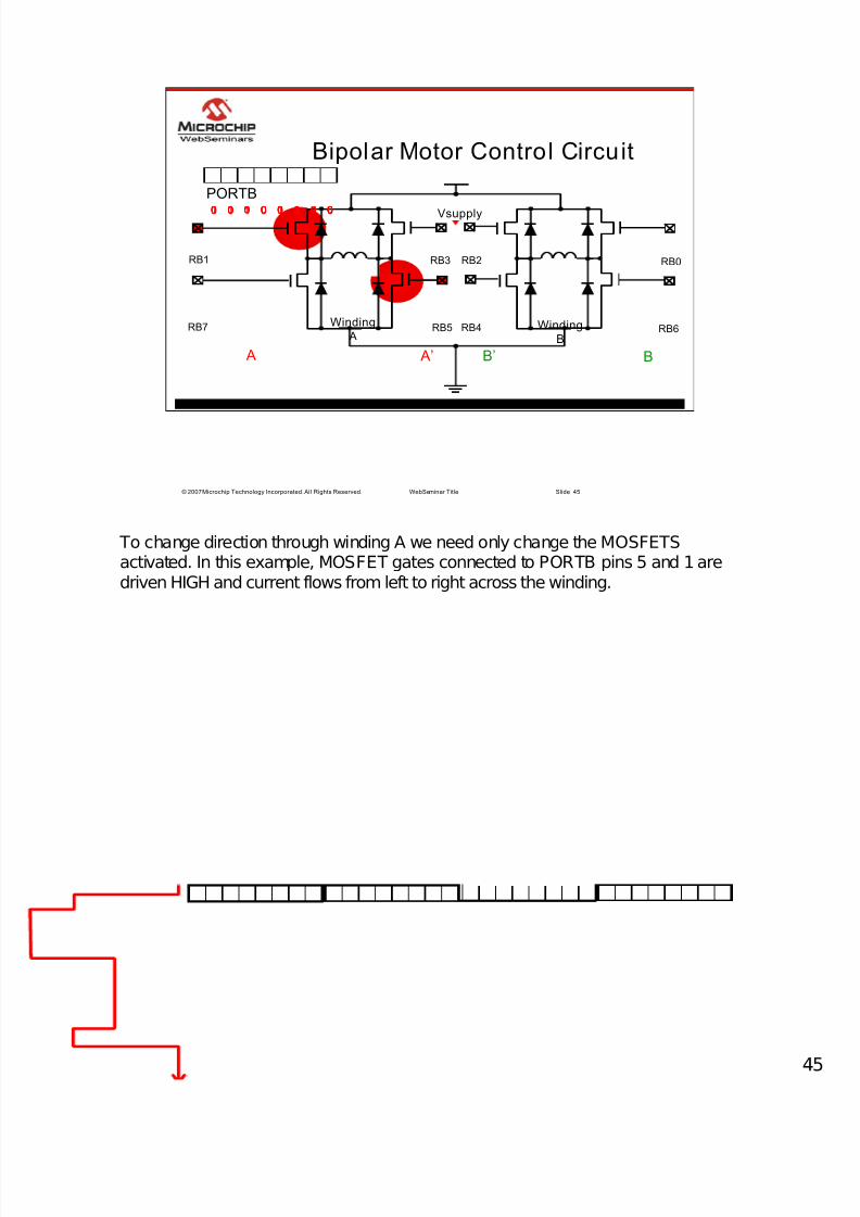
Bipolar Motor Control Circuit
Vsupply
Winding
AWinding
B
A A’ B’ B
RB2RB3 RB0RB1
RB7 RB6RB5 RB4
00100000 00010001 00100010 01000100 01000100
PORTB
To change direction through winding A we need only change the MOSFETSactivated. In this example, MOSFET gates connected to PORTB pins 5 and 1 aredriven HIGH and current flows from left to right across the winding.

7/28/2019 en543050.pdf
http://slidepdf.com/reader/full/en543050pdf 46/554
© 2007 Microchip Technology Incorporated. All Rights Reserved. WebSeminar Title Slide 46
Bipolar Motor Control Circuit
Vsupply
Winding
AWinding
B
A A’ B’ B
RB2RB3 RB0RB1
RB7 RB6RB5 RB4
00100000 00010001 00100010 01000100 00100010
PORTB
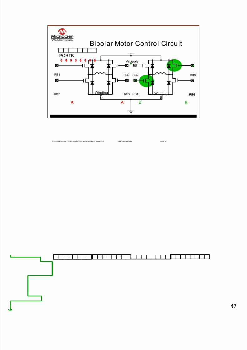
Winding B direction is controlled in the same fashion.
7/28/2019 en543050.pdf
http://slidepdf.com/reader/full/en543050pdf 47/554
© 2007 Microchip Technology Incorporated. All Rights Reserved. WebSeminar Title Slide 47
Bipolar Motor Control Circuit
Vsupply
Winding
AWinding
B
A A’ B’ B
RB2RB3 RB0RB1
RB7 RB6RB5 RB4
00100000 00010001 00100010 01000100 10001000
PORTB

7/28/2019 en543050.pdf
http://slidepdf.com/reader/full/en543050pdf 48/554
© 2007 Microchip Technology Incorporated. All Rights Reserved. WebSeminar Title Slide 48
Transistor Considerations
Winding
A
Vsupply
N-Channel
P-Channel
In the preceding drive circuit example, enhancement type MOSFETS are used. Anytransistor could potentially be used such as Bipolar and IGBT transistors. However,MOSFETs are easier to control since they are voltage controlled devices.MOSFETs also offer faster switching times than the IGBT thereby reducingswitching power loss. In the above example you’ll notice that the MOSFETs in the
upper half of the H-Bridge are P-channel type and the lower half of the H-Bridge areN-channel type. The P-channel MOSFET provides the pull-up, or charge current forthe gate capacitance and the N-channel MOSFET provides the pull-down ordischarge current for the external gate capacitance.

7/28/2019 en543050.pdf
http://slidepdf.com/reader/full/en543050pdf 49/554
© 2007 Microchip Technology Incorporated. All Rights Reserved. WebSeminar Title Slide 49
Transistor Considerations
Winding
A
Vsupply
P-Channel
OR
Vsupply
N-Channel
accommodates the
algorithm used inthis presentation
P-Channel
In this presentation however, we have been activating the upper half of the H-BridgeMOSFET gates with a positive voltage or logic HIGH. If you wish to utilize thisalgorithm, you may consider applying an inverter configuration to the gate of the P-channel type MOSFETs as shown above using an addition N-channel typeMOSFET.
7/28/2019 en543050.pdf
http://slidepdf.com/reader/full/en543050pdf 50/55
© 2007 Microchip Technology Incorporated. All Rights Reserved. WebSeminar Title Slide 50
Other Considerations
z Choosing a Power Switching Element:− Based on application
− Motor specifications (i.e. Voltage, Current
and Power ratings)
z Current limiting will be required if drivingthe motor at higher than rated voltages
Some other things to consider are the ratings of the MOSFET switching elementsused. As always, your application will dictate much of this. Attention to thespecifications for the particular motor you are using will help here paying specificattention to Current and Power ratings. Often stepper motors are driven at highervoltages than listed in their specifications in order to reduce current rise slew rates
within the coil to allow for higher step rates. However, in driving the motor at thesehigher voltage levels, current limiting practices will need to be implemented to avoiddamaging the motor.

7/28/2019 en543050.pdf
http://slidepdf.com/reader/full/en543050pdf 51/55
© 2007 Microchip Technology Incorporated. All Rights Reserved. WebSeminar Title Slide 51
Stepper Motor Control Summary
z Full Stepping− One Phase On
− Two Phase On (More Torque)
− Anti -resonance
z Half Stepping
− Improves step resolution
− Minimizes anti-resonance
− Torque reduced by half of “ Two Phase On” Full
Stepping
Summarizing full and half stepping modes. We have two options available to uswhen using Bipolar stepper motors to rotate the motor in full-stepping algorithms.One Phase On energizes one winding at a time while Two Phase On energizes twowindings at once. Two Phase On improves the torque of the motor but rememberthis type of full-stepping will also coil temperature due to power dissipation.
Half-Stepping improves step angle resolution while minimizing the effects of anti-resonance. However, nothing is free, torque is reduced by half of Two Phase On fullstepping and steps per second will need to executed twice as fast.

7/28/2019 en543050.pdf
http://slidepdf.com/reader/full/en543050pdf 52/55
© 2007 Microchip Technology Incorporated. All Rights Reserved. WebSeminar Title Slide 52
Stepper Motor Control Summary
z Drive Circui ts
− H-Bridge configuration allows bidirectional current
flow across the windings
− Switching element specifications are determined through
examination of Motor specifications
In the examples used in this Web Seminar a traditional H-Bridge configuration isused to drive the stepper motor. You could build your own using some powertransistors or utilize on of the many IC packages available on the market. As alwayswhen selecting components to interface with your motor always refer to the StepperMotors specification sheet.

7/28/2019 en543050.pdf
http://slidepdf.com/reader/full/en543050pdf 53/55
© 2007 Microchip Technology Incorporated. All Rights Reserved. WebSeminar Title Slide 53
More Information
z AN906: “ Stepper Motor Control using thePIC16F684”
z AN907: “ Stepping Motor Fundamentals”
z AN898: “ Determining MOSFET Driver Needsfor Motor Drive Applications”
z Motor Control Design Center at
www.microchip.com
For more information on topics covered in this web seminar or for furtherinformation please refer to application notes listed above. AN898 in specific goesinto greater detail on various switching components and why you would use oneover the other. You may also be interested in visiting the Motor Control DesignCenter at www.microchip.com for recommended products, application notes and
technical briefs related to Motor Control.

7/28/2019 en543050.pdf
http://slidepdf.com/reader/full/en543050pdf 54/55
© 2007 Microchip Technology Incorporated. All Rights Reserved. WebSeminar Title Slide 54
Thank You!!
My name is Marc McComb and I thank you for downloading this web seminar.

7/28/2019 en543050.pdf
http://slidepdf.com/reader/full/en543050pdf 55/55
© 2007 Microchip Technology Incorporated. All Rights Reserved. WebSeminar Title Slide 55
Trademarks
The Microchip name and logo, the Microchip logo, Accuron, dsPIC, KeeLoq,KeeLoq logo, microID, MPLAB, P IC, PICmicro, PICSTART, PRO MATE, rfPICand SmartShunt are registered trademarks of Microchip TechnologyIncorporated in the U.S.A. and other countries.
AmpLab, FilterLab, Linear Active Thermistor, Migratable Memory, MXDEV,MXLAB, SEEVAL, SmartSensor and The Embedded Control SolutionsCompany are registered trademarks of Microchip Technology Incorporated inthe U.S.A.
Analog-for-the-Digital Age, Application Maestro, CodeGuard, dsPICDEM,dsPICDEM.net, dsPICworks, dsSPEAK, ECAN, ECONOMONITOR,FanSense, FlexROM, fuzzyLAB, In-Circuit Serial Programming, ICSP, ICEPIC,Mindi, MiWi, MPASM, MPLAB Certified logo, MPLIB, MPLINK, PICkit,PICDEM, PICDEM.net, PICLAB, PICtail, PowerCal, PowerInfo, PowerMate,PowerTool, REAL ICE, rfLAB, Select Mode, Smart Serial, SmartTel, TotalEndurance, UNI/O, WiperLock and ZENA are trademarks of Microchip Technology Incorporated in the U.S.A. and other countries.
SQTP is a service mark of Microchip Technology Incorporated in the U.S.A.


