EN INSTRUCTIONS FOR ASSEMBLY, USE, AND MAINTENANCE · 8 Quality standards for wood pellet Unit of...
37
WARNING: This user manual is an integral part of the product. It has to be kept and read carefully. EN INSTRUCTIONS FOR ASSEMBLY, USE, AND MAINTENANCE PELLET STOVE LUCA S/LUKA S8
Transcript of EN INSTRUCTIONS FOR ASSEMBLY, USE, AND MAINTENANCE · 8 Quality standards for wood pellet Unit of...

WA
RN
ING
: T
his
use
r m
an
ual is
an in
tegra
l p
art
of th
e
pro
duct.
It h
as to b
e k
ept a
nd r
ead
ca
refu
lly.
EN
INSTRUCTIONS FOR ASSEMBLY, USE, AND
MAINTENANCE PELLET STOVE
LUCA S/LUKA S8

2
1. Introduction Firstly, we would like to take this opportunity to thank you for purchasing this product of ALFA PLAM.
We have prepared this brief manual for you to make the use of our products easier.
Special technical problems specified herein have to be considered by the persons involved in the putting together,
assembly, and commissioning of the product to ensure that operations are carried out as accurately as possible.
• This booklet about the installation, operation, and maintenance should be read carefully before installing and using
the product. It should be considered an integral part of the product and must be kept in a safe place.
• The procedures for installation, connecting, inspections, maintenance, repairs must be carried out by qualified
personnel.
• It is recommended that the first ignition or, rather, commissioning, is performed by qualified personnel.
• Do not use any flammable liquids for the ignition process. • This product should not be used by people with reduced physical, sensory, and mental abilities or lack of experience
and skills (including children), unless they are supervised and provided with instructions by someone who can
guarantee their safety.
• Children must always be supervised by an adult to protect them from accidental contact with hot surfaces of the
furnace, as well as to prevent them from using or touching the furnace settings.
• Please call your dealer to obtain additional information that you need which is not included in this manual. The following symbols are used in this manual: ATTENTION: Safety warning
Alfa Plam bears no responsibility or liability for any direct or indirect personal injury or damage to the property arising
from non-compliance with the indications given and highlighted in this manual.

3
1.1 Product serial number
Product serial number can be found on the label affixed to the back of the device and on the cover of this
manual.
The product serial number would be needed any time the user seeks auxiliary services.
1.2 Materials
The products of the ALFA PLAM brand usually utilise the materials with the following properties:
• Very thick sheets providing sturdier structure of the device;
• For specific models, very quality steel and materials from cast iron are used to give the product its unique
design and elegant finish;
• Before being painted at high temperature, metal parts are exposed to the treatment of phosphate so that the
painting process would reach the higher level and so as to improve the final product;
• Seals, which provide sealing of the combustion chamber, must be periodically inspected to prevent undesirable
combustion, which may occur due to excessive wear of seals;
• Glass and ceramics elements for the doors of the combustion chamber. For information regarding cleaning
procedures, see the section dedicated to maintenance.
1.3 Certification
This product respects the EN 14785 standard on radiators using wood pellets in residential areas. They also
respect the laws implemented through the following European Directives:
- 2014/30/EC (Electromagnetic compatibility directive);
- 2014/35/EC (Low voltage directive);
- Regulation 305/2011/EEC (Construction products);
Meets the requirements of
15a B-VG the Austrian local regulations
Certification issued in Switzerland

4
1.4 Dimensions
BEHIND FROM THE SIDE
IN FRONT SYSTEM
Dimensions in mm
A: The flue gas pipe diameter ø 80 B: Air intake Ø 50 cm C: Electric connections
A
B C

5
In detail
BEHIND:
1: Thermostat for manual reset
2: Room temperature sensor
3. ON/OFF switch
4: Power supply cable
1
2
3
4

6
1.5 Technical characteristics of the product
Product: LUKA S
Unit of measure Max Min.
Heating power kW 6,3 2,7
Emission of CO (at 13% of oxygen) % 0,0136 0,0213
Efficiency % 85,57 92,27
Rated electric energy W 380
Rated voltage V 230
Rated frequency Hz 50
Fuel Pellet
Fuel consumption per hour kg/h 1,608 0,642
Flow of the gas mass g/s 7,77 3,6
Gas combustion temperature °C 125 69
Minimal suction pressure Pa 12,0 12,0
Tank capacity kg 20
Autonomy h 11 28,6
Energy required for operations W 90
Flue gas release mm ∅ 80
Combustion air intake mm ∅ 50
Net weight kg 136
Combustion volume* m3 157
15a.Technical characteristics of the product Product: LUKA S8
Unit of measure Max Min.
Heating power kW 7,58 2,64
Emission of CO (at 13% of oxygen) % 0,0149 0,0207
Efficiency % 85,36 91,56
Rated electric energy W 380
Rated voltage V 230
Rated frequency Hz 50
Fuel Pellet
Fuel consumption per hour kg/h 1,950 0,633
Flow of the gas mass g/s 8,40 4,00
Gas combustion temperature °C 139 67
Minimal suction pressure Pa 12,0 12,0
Tank capacity kg 20
Autonomy h 11 28,6
Energy required for operations W 90
Flue gas release mm ∅ 80
Combustion air intake mm ∅ 50
Net weight kg 136
Combustion volume* m3 137

7
* The values are calculated in accordance with the law for households with a heat consumption of 60 W/m3 and a height of 2.6 m.
1.6 Fuel characteristics The furnace is first of all characterised by the fact that it burns natural fuel (wood pellets), which are environmentally derived from waste from the wood industry (chips/sawdust). Once the chips and sawdust which arise in the processing of wood are properly cleaned and dried, they are compressed under extremely high pressure to produce small cylinders of pure wood pellets. Each tiny cylinder may vary in length and width from 1 to 3 cm in length and from 6 to 8 mm in the radius Wood pellets are primarily characterised by low humidity (below 12%) and high density (= 600 kg/m3), as well as by its uniformity and compactness, which gives this type of fuel high caloric
value (DTV 41005000 kcal/kg).
Wood pellets used as fuel for this furnace must have excellent quality characteristics, such as, for example, those defined by DIN 51731, ÖNORM M 7135 and EN plus A1 standards, for which many basic characteristics are listed below.
⚠ ATTENTION: As is required by the relevant European laws governing the characteristics
of commercial fuels, the pellets must be manufactured exclusively using chips of
unprocessed wood, without added substances.
It is strictly forbidden to use any liquid or solid fuel except wood pellets.
⚠ ATTENTION: In order to operate the furnace at the best level, it is recommended to use
the wood pellets certified by an accredited body. Using other types of pellets compared
to those specified by the manufacturer can lead to failure of the furnace and may void
the warranty.
Storage and handling of wood pellets are important tasks that must be performed carefully.
- The fuel has to be stored in a dry and warm place. - Pellets must be handled so as to prevent excessive crushing and turning into a fine powder.
Compliance with these simple rules will allow better combustion efficiency and even help
maintain proper operation of moving mechanical parts.
⚠ ATTENTION: If the device is not used during a sufficiently long period of time (more than fifteen days), all the remaining pellets have to be removed from the tank to prevent it from becoming too wet as this may cause a malfunction of the product.

8
Quality
standards for
wood pellet
Unit of
measure
ÖNORM M 7135
DIN 51731
DIN plus
EN plus A1
Diameter mm from 4 to 10 from 4 to 10 from 4 to 10 6 ± 1
Length mm 5 x P1 < 50 5 x P1 3.75<D<40 3
Density Kg/dm3 > 1.12 1.0 - 1.4 > 1.12 >0,6 (aver. vol. mass)
Humidity % < 10 < 12 < 10 < 10
Ash % < 0.50 < 1.50 < 0.50 < 0.50
Heating power
kWh/kg > 5 4.86 - 5.42 > 5 > 4.5
Sulphur % < 0.04 < 0.08 < 0.04 < 0.05
Nitrogen % < 0.3 < 0.3 < 0.3 < 0.3
Chlorine % < 0.02 < 0.03 < 0.02 < 0.02
Dust % weight < 2.3 - < 2.3 < 1
Binders % pressed
mass
< 2 2
< 2
1 At most 20% may have the length 7.5 times greater than the diameter D
² DIN bans the use of any additional substances. However, this ban does not apply to
small heating systems.
2 At most 5% pellet may have length exceeding 40 mm, max. 45 mm.
1.7 Safety recommendations
⚠ ATTENTION: Read the enclosed manual carefully before installation.
⚠ ATTENTION: The burning unit has to be emptied before the device is activated in the event any
difficulties occur during the activation of the device. It is strictly prohibited to use any other type of solid or liquid fuels other than wood pellets with the
radius of 6 mm, for which the furnace was designed. Avoid using wet or crushed pellet. In order to operate the furnace at the highest level, the use of wood pellets certified by an
accredited body is recommended. Using other types of pellets compared to those specified by the manufacturer may lead to failure of the furnace and may void the warranty.
When feeding the pellets, be careful the pellet does not fall into another internal part of the furnace other than the suitable container for the pellet.
⚠ ATTENTION: If you are unable to ignite the furnace, you will have to empty the furnace. Unless
you do so, it may cause excessively strong burning that can lead to significant amounts of smoke.
⚠ ATTENTION: Do not open the doors or pull out the power cable during the ignition phase
or shutdown, or while the furnace is in operation, even if the combustion chamber is blocked or
overloaded; start the process of shutting down and wait for the furnace to complete the phases of
work before you solve the problem. Do not attempt to reignite the furnace until the problem is
resolved.

9
⚠ ATTENTION: Do not interrupt the shutting down procedure (by, for example,
pulling out the power cable) until it is finished.
⚠ ATTENTION: If wood pellets accumulate in the combustion chamber while the device is in
operation, immediately unplug the machine and turn it on using the greater ventilation program. If the pellets continue to accumulate, try using other types of wood pellets, or call the department for assistance.
⚠ ATTENTION: Never feed the pellet manually into the combustion chamber.
⚠ ATTENTION: To present injuries, always follow the notes on adequate use
contained in this manual for the device and its electrical components.
⚠ ATTENTION: The installation procedures, connecting of the inspection, maintenance and
repairs may
performed only by qualified personnel.
⚠ ATTENTION: The product must be installed in full respect of the applicable legal standards.
⚠ ATTENTION: Always follow the safety recommendations and safety standards given by this
manual.
⚠ ATTENTION: Any person who performs the interventions on the product must first read and fully
understand the contents of this manual and be fully familiar with the control panel of the product.
⚠ ATTENTION: The product may be used, changed and programmed only by adults. In accurate or
random settings may lead to dangerous situations or malfunctions.
⚠ ATTENTION: The company Alfa Plam bears no civil or criminal liability for damages in the event
the product is subjected to unauthorised repairs or replacement of parts.
⚠ ATTENTION: While the product is in operation, some of its surfaces may reach extremely high
temperatures. Therefore, the user is advised to take all the necessary precautions, especially when children or elderly or disabled people are present.
⚠ ATTENTION: Do not cover or close the hot air outlet in any way. Do not cover the product with
any cloth or any similar material.
⚠ ATTENTION: To avoid accidental tipping over of the furnace, never lean or place too much weight on the open door while the cleaning procedure is in progress. It is recommended to avoid this kind of pressure and take the necessary precautions, especially when children or elderly or disabled people are present.
1.8 General recommendations
⚠ ATTENTION: Never use the product for purposes other than those for which it is designed
and manufactured.
⚠ ATTENTION: The product must not be used for cooking.
⚠ ATTENTION: The product should not be used in the event of any failure or malfunction. In
such a situation, disconnect the power cord from the socket immediately.
NEVER leave the product door open while the furnace is operating.
Pipes have to be regularly inspected.
NEVER use steam for cleaning of the product.
Always consult qualified and authorised personnel for any service interventions that may be necessary. Use only the original spare parts.

10
Fuel in the burner can be fed only through an automated feeding system and not directly by the user.
⚠ ATTENTION: In the case of "failed ignition“, you must remove all the pellets deposited in the
combustion chamber before you try to re-ignite the furnace. The pellet removed from the
furnace must not be returned to the tank.
This manual must be considered an integral part of the product and must be used over its
entire service life. It has to be kept at a safe location. In case the manual is lost or damaged,
a replacement copy can be obtained from your dealer.
1.9 Safety device
The product is equipped with the following safety devices:
• Thermostat for determining the temperature of the tank: This device shuts down operation
of the product each time the set safety limit is exceeded;
• Meter for determining the temperature of smoke: this element establishes the temperature
of smoke and continually monitors the proper functioning of the product;
• Pressure switch: this element assesses whether the pipe is clogged;
• Thermometer for the environment: this element constantly monitors the temperature of the
room where the furnace is located;
• Modulation mode of operation: if the flue gas temperature exceeds the set safety threshold,
the device will automatically reduce the amount of pellets for burning until the temperature
drops below the pre-set limit.
Incorrect parameter settings can lead to exceeding the safety limits and can lead to excessive consumption of pellets. The exceeding the safety limits can also be caused by poor ventilation of the environment in which the furnace is located which presents the device to get enough cold air
IT IS FORBIDDEN TO shut down the safety devices. When you eliminate the cause of the security system activation, the device can be restarted in order to restore its proper functioning.
⚠ ATTENTION: The device must be installed in such a way that the electrical cable can be
easily reached.
Note: The security section is made taking into account the normal conditions of use of the
product described and specified in the chapter 3. The company Alfa Plam bears no
responsibility for any personal injury or property damage that may occur if the furnace is not
used in accordance with the conditions specified in this user manual. The company Alfa
Plam also bears no responsibility for any personal injury or property damage that may occur
if the user fails to comply with the following regulations:
A) They must take all the necessary measures and precautions to ensure that no party
activates equipment until the repairs, adjustments, replacement, or maintenance operations
are completed;
B) Do not remove or change any safety devices on the device;
C) The device must be connected to the system for extracting of smoke which is
functioning correctly;
D) Make sure that the environment in which the furnace is installed is sufficiently ventilated,
as prescribed in this manual.

11
1.10 Environment for the use of the product
⚠ ATTENTION: The device must be installed in an environment with ventilation, whereas in
accordance with the current regulations it must be provided with sufficient combustion air. This is important to ensure its proper functioning.
⚠ ATTENTION: The room must have a capacity of not less than 20 m3 and must possess all the
necessary ventilation conditions, as described in Chapter 2 of this manual. These conditions will provide the necessary air flow to allow for proper combustion (40 m3/h).
IT IS FORBIDDEN TO use the product in bedrooms and bathrooms.
IT IS FORBIDDEN TO use the product in spaces with another heating appliance already installed which does not have its own system for air intake.
IT IS FORBIDDEN TO install the product near flammable materials.
IT IS FORBIDDEN TO set up the product on the floor made of combustible material unless it the protective plate of non-flammable material is used.
IT IS FORBIDDEN TO use the product in explosive and potentially explosive atmospheres.
⚠ CAUTION: You might sense an unpleasant smell of paint when lighting the stove for the
first time. If this happens, keep the stove running at maximum power during the first few days to burn off the paint as quickly as possible and make the unpleasant smell disappear. Make sure that room in which stove is installed is well ventilated.
12
2 Installation
You must comply with all local and national laws and European standards in terms of installation,
use, and maintenance of the device.
2.1 Placing of the device
Our product creates heat by bringing in the air necessary for combustion process directly from
the environment that is being heated.
For this reason, and because of basic safety for the furnace users, the device should always be
installed inside an adequately ventilated environment to ensure a steady flow of combustion air.
Therefore, it is necessary to install the air intake openings that are connected with the air outside
(as shown in Figure 2.1)
In accordance with the provisions laid down in UNI 10683 standard, air intakes must have the following characteristics:
1. Have to have internal cross-section of not less than 80 cm2; 2. Have to be placed approximately at the level of the floor;
3. They must be adequately protected by wire mesh or grate so that the minimum radius
requirement for air flow is not diminished;
4. Have to be placed so that they are not covered in any way.
Adequate fresh air flow can also be provided using the opening to the next room, if the room
is equipped with direct ventilation and does not present a risk of fire, such as a warehouse,
garage or storage, as required by the UNI10683 standard. It is recommended to avoid placing the furnace in the rooms where there are devices which do
not have a closed system in relation to the environment or in the rooms where there are devices
which may reduce the pressure in the room itself in relation to the external environment, because
it may mead to the problems with weak air intake for our product (UNI 10683).
⚠ ATTENTION: It is forbidden to release the furnace combustion products into the shared pipe.
When checking the compatibility of the system, it is recommended to determine if the surface of
support (floor) has adequate load capacity (kg) to hold the weight of the product. If this is not the
case, it is recommended to take appropriate safety measures (for example, to use a panel for
the distribution of freight).
When installing the furnace, it is advisable to set the appropriate distance from the wall to allow
access to the back of the furnace (we recommend at least 20 cm) and to the side (we
recommend 80 cm). Such a space may be required, for example, in order to allow adequate
cleaning.

13
Picture 2.1: An example of the necessary air opening
Never let the flammable materials get close or come into contact with the outer surfaces of the combustion chamber, as these can reach extremely high temperatures when the product is in operation.
If the floor is made of flammable material (e.g. hard wood), it is recommended to protect it by placing a layer of non-flammable material under and around the stove.
For more information on the minimum safe distance from the flammable materials (see figure
2.2.a):
- Minimal distance from the flammable floor (F = 4 cm);
- Minimal distance from the flammable back wall (P = 20 cm);
- Minimal distance from the flammable side wall (L = 40 cm);
- Minimal distance from the flammable material on the front side (R = 80 cm).
Once you've determined where you will set up the furnace, it is possible to adjust the legs that tilt the furnace to reach the appropriate height.
A
A

14
back side side
front
Picture 2.2.a: Distance at installation
2.2 Pipe characteristics
The main characteristics of the pipe are given below, in accordance with the requirements of
the standard:
- Inspection valve (I); - Maximum height of the pipe which is connected directly to the smoke outlet in the furnace should be between 2 to 3 m;
- If you need a horizontal segment, ensure that it does not exceed 1.5 m in length and the inclination of 3 to 5% in order to help extract the smoke;
Use the end portion that is resistant to wind and water to prevent the changing of conditions of slightly higher pressure of the pipe (do not place the horizontal end at the end of the pipe); Condition of somewhat greater pressure in the pipe is needed to facilitate the flow of smoke
from the combustion chamber.
Please note that any removal of excess heat is carried by the electric control part (modulation, shutting down, etc.).

15
- The exhaust duct must be made of materials that are resistant to combustion products and moisture (the review will enable the removal of any moisture); - Ducts must be manufactured in such a way to prevent any leakage of smoke. - The duct must be isolated, especially the outer part which is exposed to atmospheric conditions.
Avoid using completely horizontal segments
Min 3-5%
Ø80
Ø80 Max 2-3m H>5m
Picture 2.3: Exhaust duct
The room in which heating body will be mounted should not have aspirators because they can reduce pressure in the environment.
It is strictly forbidden to close all the air openings.
The exhaust duct should be cleaned at least once a year; we recommend that you perform a thorough cleaning of the exhaust channel and its connection.
After a period of not being used and before the activation, check whether there are any obstructions
⚠ ATTENTION: The exhaust duct has to be built in accordance with the provisions of the standard.
⚠ ATTENTION: Use the adequate tool to check whether the chimney has the minimal suction power of 10 Pa.
2.2.1 The smoke exhaust towards the outer wall
One solution that can be used includes placing the pellet furnace near the outer wall of the house
so that the exhaust gases are released directly to the outside (Figure 2.4). Some of the notes set
forth by the standard for this type of system configurations are listed below:
- Always make sure that there is a valve for inspection (i) to enable regular cleaning procedures
and removal of moisture that can form;
- The end element on the chimney (T) has to be such to be wind and water resistant;
- Please note that the pipe is properly insulated in the section that passes through the wall.
If the pipe for the removal of exhaust gases is located outside, it must be made of double wall
and stainless steel to provide greater resistance to atmospheric conditions, as well as the
proper temperature of exhaust gases themselves.

16
2.2.2. Smoke outlet at the roof through the traditional chimney
Exhaust gases from the furnace can be removed via a traditional chimney already built (Figure
2.5), if it meets the standards required. The standard highlights the main characteristics of a
good chimney (C), which are summarised below:
- Proper insulation, before most in the outer part exposed to atmospheric conditions;
- The constant inner radius (no segments with smaller radius);
- It must be made of a material which is resistant to high temperatures, the effects of the
combustion products and to the corrosive effects of moisture which may occur;
- Generally in the vertical position, without departing from the vertical angles greater than 45 °.
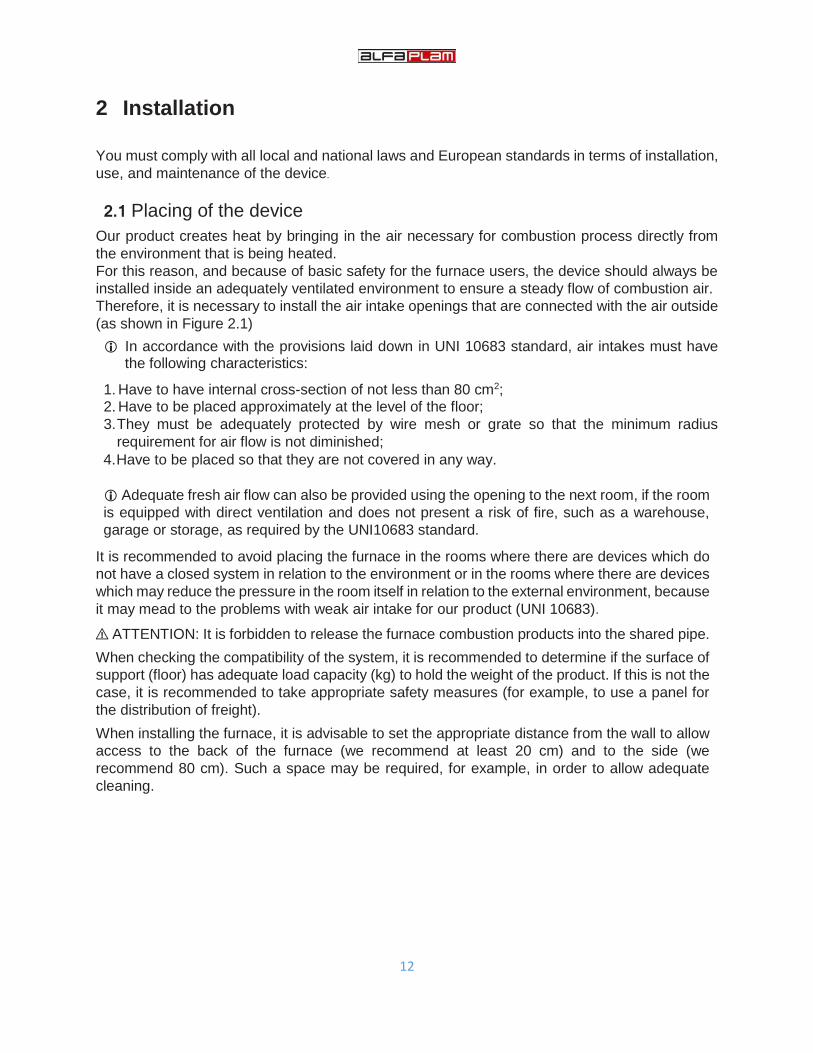
It is recommended that the base of the chimney to be equipped with a chamber for collecting of solid matter i.e. moisture (R). The chamber has to be accessible through air-tight door (I). H>0.50m H>0.50m
Picture 2.4: The smoke exhaust towards the outer wall Figure 2.5: Smoke outlet at the roof through the traditional chimney
It is recommended to follow the guidelines laid down by standards in relation to the size and
radius of the chimney (C). In any case, never use exhaust duct with internal radius of less
than 100 mm.
In the case of exhaust ducts of larger radius, a steel pipe (A) has to be placed inside the
chimney bricks or mortar (C), as shown in Figure 2.6.
Steel pipe must be isolated by a suitable heat-resistant materials, such as rock wool or
vermiculite (B), and must be separated from the outer edge of the chimney.
17
H>0.50m C
B A
Picture 2.6.An example of the connecting with the chimney
In case of fire in the chimney or pipe, immediately turn off the furnace and disconnect it from the mains.
2.3 Dismantling and disposing of waste
The packaging consists of materials which are not toxic or harmful. Special conditions for its
disposal are not required. The user is responsible for disposal of the remaining packaging
components. He must take the proper disposal procedures in accordance with the applicable
standards in the country where the product is installed.
⚠ ATTENTION: The elements of the packaging must be kept out of the reach of children who
are not supervised or persons with disabilities
2.4 Electric connections
The product may be connected to the mains only after the electrical isolation is installed. Connect the product to the household power grid. Just press the main switch on the rear panel if you want to turn on the device. After you do
this, the furnace will be ready for ignition. For the ignition and programming procedures, see Chapter 4.
2.5 Room temperature meter Room temperature meter may be adjusted only after the electric installations have been
connected.
This meter allows the temperature in the room where the furnace is installed to be continuously
monitored. Setting the room temperature meter in a proper position would provide proper operation of the product.

18
3 Use of the product
3.1 Necessary controls and checks for first ignition
The following instructions have to be observed during first ignition:
• Check whether all safety requirements have been met (see section 1.8);
• Connect the device to the power supply only when you are sure that the supply voltage is 230
V 50 Hz. When you confirm this, change the position of the switch on the back panel to “ON”
position;
• Make sure that the display on the control panel is on, it indicates that the device is properly
plugged to the power supply;
• Make sure there is enough fuel in the tank for the anticipated period of work.
The fuel must be in accordance with the instructions given in the relevant section of this manual.
Painted parts of the furnace can emit odorous fumes during the first few ignition. This
phenomenon is associated with a chemical stabilisation process in the used paint. For this
reason, during this period, the room where the furnace is located must be regularly and well
ventilated.
3.2 Fuel feed
Open the upper doors of the product to insert the pellet. With regard to fuel, you must comply
with notes contained in the relevant part of this manual.
⚠ ATTENTION: Do not allow the bag with wooden pellets to come into contact with hot parts
of the product during the fuel feeding.
⚠ ATTENTION: Do not remove the protective mesh within the feeding unit.
⚠ ATTENTION: Do not transfer the full weight of the bag containing the fuel on the product itself.
⚠ ATTENTION: After the feeding of the pellets is completed, close the upper door. Periodically check the quantity of wood pellets contained in the tank and fill it in time.
⚠ ATTENTION: Excessive moisture can cause the pellet to be crushed into a fine powder
which can lead to the increased sedimentation in the area of the boiler, even to the blockage
of the feeding system (auger).
When loading the pellets, make sure that the pellets do not accidentally fall into the other internal parts of the machine, except in a suitable container.
Only use the pellet with the diameter from 6 to 8 mm. Pellet feeding

19
4 Furnace management system
In the furnace, an advanced control system is installed which provides a safe, efficient and reliable management of the operation and maximum functional use of the furnace. It is characterised by:
Simplicity of settings and use,
Simple and direct user functions,
Reliable and flexible functional software developed specifically for pellet furnaces,
Advanced features are available for installers in order to adapt different configurations and installations
4.1 Electric wiring scheme

20
4.2 The control panel (display): use and functions
4.2.1 Display K100
The main frame shows: time and date, Chrono activation, combustion energy, heat energy, functional condition, the current room temperature, set room temperature, LEDs
Presentation Explanation Main Temp. The current value of the room temperature
State Functional condition of the furnace Main Therm. The set room temperature Comb. Power Combustion power Heat. Power Heating power
Time Time Chrono The programmed work
Button Function
P1 Exit from the menu/sub-menu
P2 Switching on and off (hold down for 3 seconds), resetting of errors (hold down for 3 seconds), Chrono activation and deactivation
P3 Entering the User menu 1 /submenu, entering the User menu 2 (hold for 3 seconds), data storage
P4 Entry to the visualisation menu, increasing
P5 Entry to the visualisation menu, decreasing
Led Function Led Function
Pellet shortage The set room temperature has been achieved
Air flow direction Remote thermostat temperature achieved (if remote thermostat is
connected)
4.2.2 Alarms
Description System condition Code
Safety error - safety thermostat: signals when the system is off Block Er01
Safety error - pressure control: signals only if the combustion fan is turned on
Block Er02
Shutting off in case the flue gas temperature is less than permitted Block Er03
Shutting off in case the flue gas temperature is higher than permitted. Block Er05
Pellet thermostat is activated Block Er06
Fan encoder error: No encoder signal Block Er07
Fan encoder error: failed combustion fan regulation Block Er08
The date and time are not correct due to a longer power outage. Block Er11
Ignition failed Block Er12

21
Power outage Block Er15
Error in communication - Display disconnected Block Er16
Error in the air flow regulator Block Er17
No more pellets Block Er18
Air flow sensor damaged. Block Er39
Minimal air flow during the check phase not achieved Block Er41
Maximal flow of air achieved (F40) Block Er42
Auger encoder error: No encoder signal Block Er47
Auger encoder error: failed auger regulation speed Block Er48
Module error I/O 12C Block Er52
Repair shop error. Informs that the planned period of operation has been reached (after the pre-feeding): the system will stop only when it moves to the work mode.
Block Repair shop
4.2.3 Other messages
Description Code
Error on the probe during the control in the check phase Prob
Notifies that the planned period of work has been achieved. The furnace or the boiler have to be cleaned.
Clean
The message appears if the system is turned off during ignition (after pre-feeding) by the external device: the system will stop only when it switches to an operation mode.
Block ignition
There is no communication between the mother board and the display (keyboard). Link Error
Periodical cleaning in progress. Cleaning On
4.2.4 Visualisations
By pressing the P4 or P5 button, the visualisation menu is entered. Here you can see the value of the room temperature at any time, the flue gases, engine speed of flue gases, ON time for the auger, etc. The following indicators of the furnace work can be checked in the visualisation menu:
Display Description
Exhaust T. [ºC] 103 Flue gas temperature
Room T. [ºC] 25 Local room temperature;
Rem. Room T. [ºC] 25 Remote room temperature; only visible if the remote thermostat is active
Air Flux 750 Air flow; visible only if the primary air flow meter is active
Fan Speed [rpm] 1250 Exhaust gas fan speed;
Auger [ºC] 1.2/450 Auger ON time/ Auger speed;
Cleaning [h] 450 Woking hours remaining before cleaning of the furnace; only visible if timer is activated
Work time [h] 2985 Total working time of the furnace in the operative mode, modulation and safety
Ignitions [h] 106 Number of ignition attempts
Product Code: 494 - 0000 Product code
4.3 User menu 1 Press the P3 button for 1 second to enter the User menu 1.

22
Use the P4 and P5 buttons to scroll through the various submenus (combustion management, heating management ...) and then press the P3 button to select any submenu.
Combustion Management Combustion management
Power In this sub-menu, it is possible to modify the system combustion power. Use the P4 and P5 buttons to select from 5 powers (Power 1, Power 2, Power 3, Power 4 and Power 5). When the desired power is selected, press P3 button to confirm. Exit the sub-menu by pressing the P1 button.
Auger Calibration Enables the modification of the value set for the duration of the ON time of the auger. The values range from -7 to 7. The factory value is 0. (See item 4.6.2)
Fan Calibration Enables the modification of the value set for the flue gas motor speed. The values range from -7 to 7. The factory value is 0. (See item 4.6.3)
Heating Management Heating management
Room Thermostat This menu allows you to modify the value of the set local room temperature (the room where the furnace is installed). The value of the temperature set in this menu represents a condition for the work of the furnace. In fact, the furnace will operate in the selected mode until it reaches the set temperature. When the setpoint is reached then the furnace goes into standby mode of work or it works with the minimum power. The furnace exits the modulation state and returns to normal operation as soon as the room temperature falls below the setpoint. The temperature value is adjusted by pressing P4 and P5 and then the set value is confirmed by pressing P3. Exit the sub-menu by pressing the P1 button.
Remote Room Thermostat This menu enables the modification of the remote room thermostat value. It is visible only when the external thermostat is installed, whereas a heating plant that uses it is set to use an external thermostat.
Remote Control Remote control
This menu allows you to enable or disable the options for remote control.
Chrono Chrono
Chrono program Used for scheduling of operation of the furnace or for switching on and off the furnace in regular intervals.
Manual Load Manual feeding
This procedure activates the manual feed of the pellets with the activation of the set modality of the auger motor. The feeding is terminated automatically after 600 seconds. The system has to be off for the function to be activated.
Cleaning Reset Cleaning reset
Menu for the resetting of function “System maintenance 2”. Visible only if the option “System maintenance 2” is active.

23
4.3.1 Chrono
For the setting of the programmed work of the furnace, it is necessary to enter the Chrono menu. The Chrono menu is accessed in the following manner:
- Press the P3 button for 1 second to enter the User menu 1. - Pressing the P4 and P5 buttons opens the sub-menus until the sub-menu Chrono is reached. - Press the P3 button again to enter the Chrono sub-menu. - The following message appears on the display:
Chrono
Modality
Chrono
program
Modality
Chrono program By pressing the P4 and P5 buttons, the Modality or Chrono program is selected, after which the P3 button
is pressed to enter into one of these two sub-menus.
4.3.1.1 Modality Allows you to select the desired modality or disables all set programs.
By pressing the P2 button, the programming is turned off (disabled), or turn on (enabled)
Use P4 and P5 buttons to choose the desired mode of programming of the furnace - daily, weekly or weekend.
By pressing the P3 button, the selected mode of programming is confirmed.
Save your settings by pressing the P1 button.
Disabled
Daily
Weekly
Week End

24
4.3.1.2 Chrono Program
Chrono program provides three types of programming: Daily, weekly, and weekend. After entering the Chrono program, the following message appears on the display:
Chrono
Modality
Chrono
program
Daily Weekly Week-end
The system allows three types of programs: daily, weekly and weekend. Selection is made by pressing P4 and P5 and then entering the selected program by pressing P3.
1. Daily programming By entering the submenu Daily, i.e. the daily program, the following screen appears on the display:
Use the P4 and P5 buttons to select the day of the week. When the day is selected, press P3 button. Setting the time of activation and deactivation of the program for the selected day shall be done as follows:
Enter the change of time (the selected time flashes) by pressing the P3 button.
Change the time using the P5 or P4 buttons.
Save using the P3 button.
Activate (“●” will appear) or deactivate the time period (“○” remains) by pressing P2. Example: Choose, for example, Monday and press P3 button. Then press the P3 button and ON time (time of turning the furnace on) will start to flash. Use P4 and P5 buttons to set the desired ON time and confirm the selection with P3. In this manner, the ON time may be adjusted to, for example, 09:30. When On time is set, press the button P5 and then OFF time (turning off the furnace) flashes. Use P4 and P5 buttons to set the desired OFF time and confirm the selection with P3. In this manner, the OFF time may be adjusted to, for example, 11:15. At the end, press P2 to activate the set program. The following message occurs on the display:
Daily
Monday
ON OFF
● 09:30 - 11:15
○ 00:00 - 00:00
○ 00:00 - 00:00
This program envisages that the oven activates on Monday at 9:30 and will be deactivated at 11:15. Save your settings by pressing the P1 button. In the daily programming it is possible to switch the program from the previous day to the next day. Procedure is as follows: Select the day of the week for programming and setting the ignition and shutdown time. Set the clock to ON on the previous day at the desired time, for example 20:30. Set the clock to OFF on the previous day at 23:59. Set the clock to ON on the following day at 00:00. Set the clock to OFF on the following day at the desired time, for example 6:30. The system turns on at 20:30 on Tuesday and off at 6:30 on Wednesday.

25
2. Weekly programming For weekly programming, the programs are the same for all the days of the week. Entering the submenu Weekly, i.e. the weekly program displays the following screen on the display. The programs are activated and deactivated in the same way as in the daily programming.
3. Weekend programming For weekly programming, it is possible to choose between programs:
- Mon-Fri - Sat-Sun
The selected programs will be active for the days from Monday to Friday or Saturday and Sunday. The programs are activated and deactivated in the same way as in the daily programming.
Weekly
Mon-Sun ON O
OIsključeno
○ 00:00 - 00:00
○ 00:00 - 00:00
○ 00:00 - 00:00
Week-end
Mon-Fri ON
Isključeno
○ 00:00 - 00:00
○ 00:00 - 00:00
○ 00:00 - 00:00
4.4 User menu 2 Press the P3 button for 3 seconds to enter the User menu 2. Use the P4 and P5 buttons to scroll through the various submenus (Keyboard Settings, Keyboard Menu ...) and then press the P3 button to enter the desired submenu
Keyboard Settings Keyboard setting
Time and Date It is used for setting the day, month, year and current time.
Language Menu for the change of language.
Keyboard Menu Keyboard menu
Learn menu Allows you to manually update the menu; Access is protected by a four-digit password and procedures cannot be interrupted when it starts. In the case of a failed saving or changing of the menu, this procedure begins automatically.
Set Contrast The menu used for regulating the LCD screen contrast.
Set minimum Light Menu that is used to regulate the brightness of the LCD screen when the controls are not used.
Keyboard Address This menu is password protected and is not available to the user.
Node List This menu displays the following: communication address of the board, typology of the board, firmware code and firmware version. The data cannot be changed. Board typologies that may occur are the following: MSTR Master INP Input KEYB Keyboard OUT Output CMPS Composit SENS Sensor COM Communication
Acoustic Alarm Enables the activation or deactivation of the keyboard alarm.
System menu Menu for entering the technical menu. The access is password protected and is not available to the user.

26
4.5 Ignition of the furnace and the functional states The furnace activates by pressing the P2 button longer than 3 seconds. The following functional conditions of the furnace follow in sequence:
4.5.1 Check Up
At the verification stage, the initial checks of the input signals of the furnace are performed or of the probes and pressure switches. At this stage, the flue gas motor runs at maximum speed, whereas the auger and the lighter are deactivated. The check phase takes a few seconds and the successful test is followed by the ignition phase.
4.5.2 Ignition The ignition phase consists of four interchanging sub-phases, namely the following: - Preheating phase - Pellet pre-feeding phase - Fixed ignition phase - Variable ignition phase During the entire duration of the ignition phase, the display shows the message IGNITION. There are no special markings on the display for sub-phases.
4.5.2.1 Ignition Preheating
At this stage, the warming of the lighter takes place before the dosing of pellets starts. In order for the ignition of pellets to be as efficient as possible, it is recommended that the lighter is already warmed up at the time when the dosing of pellets starts. At this stage, the lighter is active and the auger is inactive. Flue gas motor runs at lower speeds to boost heating of the lighter.
4.5.2.2 Ignition Preload
At this stage, the initial dosage of pellets occurs i.e. the auger needs a certain amount of pellets for the ignition. At this stage, the lighter, auger, and flue gas motor are active.
4.5.2.3 Ignition – Fixed Phase
This phase represents a fixed time period that lasts 180 seconds and in case the requirements for the ignition of the furnace are reached before the expiration of this phase, it will always last until the end and only after the expiration of the fixed period, the furnace will move into a stabilisation phase. At this stage, the lighter, auger, and flue gas motor are active.
4.5.2.4 Ignition – Variable Phase
This phase occurs after a fixed ignition phase. The duration of this phase is a variable period that lasts until the moment of fulfilment of the conditions for ignition or achieving of the flue gas temperature of 50°C. In the event that the condition for the ignition of furnace is reached before the expiration of this phase, it is stopped and the next phase - the stabilisation phase takes place. At this stage, the lighter, auger, and flue gas motor are active.
4.5.3 Stabilisation
The stabilisation phase is a transitional state between the ignition phase and the work phase. This stage begins when the ignition condition is meet i.e. when the temperature of flue gases reaches 50°C. It lasts three minutes and during that time the auger, flue gas motor, and lighter are active.
4.5.4 Normal – Run Mode
After the stabilisation phase, the working mode of the furnace is activated. At this stage there are five power levels that can be adjusted as explained in the User menu 1. At this stage, the igniter is turned off while the auger, flue gas motor and the ambient motor are active and work with different intensities depending on the level of power of the furnace. The furnace works at the set power until it comes to the fulfilment of conditions for modulation.

27
4.5.5 Modulation
The furnace moves to the modulation condition when one of two conditions is met: 1. Once the furnace reaches the set room temperature, 2. When the temperature of the flue gases reaches the value above 250°C
In a modulation state, the furnace is working with minimal power - power 1 until the temperature decreases below the threshold.
4.5.6 Safety The condition Safety occurs when flue temperature of flue gas exceeds 275°C. In this phase, the dosing of pellets stops until the temperature of the flue gas decreases. If there is no temperature reduction in the next 60 seconds, the furnace goes into an Alarm state and displays a message Er05.
4.5.7 Extinguishing
The furnace shuts down by pressing the P2 button longer than 3 seconds. Then a shutdown phase follows in which the dispensing of pellets stops and the flue gas motor and ambient fan are operating at maximum capacity in order to cool the oven as soon as possible. Minimal duration of the shutting off phase is 30 seconds, and the condition for the furnace to cool down completely is for the temperature of flue gases to be less than 68°C.
4.5.8 OFF
In this state, the furnace is turned off i.e. no output on the furnace (flue gas motor, ambience fan, lighter and auger) is active.
4.5.9 Block
The blockage condition occurs in the event of error or alarm. In the block mode, the fan of the exhaust gases, auger and lighters are off. To exit, hold P2 pressed for 3 seconds: if it is no longer blocked and there is no cause for alarm, the system will shut down.
4.5.10 Ignition Recover The furnace moves to this phase in two cases:
1. If a power failure occurs during the operating mode and the flue gas temperature is higher than 50°C. 2. Pressing the main switch at the moment when the furnace is in the shutting down phase.
4.6 Other functions
4.6.1 Voltage shortage management In the event of power failure, the system keeps the most important functional data. With the return of the voltage, the system assesses the saved data and:
If the furnace is turned on and the temperature of the exhaust gases is higher than 50°C, the system switches to the Ignition recovery. By pressing the P1 button, a sudden new ignition of the system is possible.
If the furnace is on, but the temperature of exhaust gases is less than 50°C, the system enters shutdown with error Er15.
If the furnace is switched off or during shutting off or while blocked, the system returns to its previous state.
In the absence of voltage over a period of one week, the system becomes blocked with an error message Er11 indicating that the DATE / TIME is not accurate. Deblock using the P1 button, the value of TIME flashes, signalling the need for updating the TIME and DATE with the function CLOCK.
28
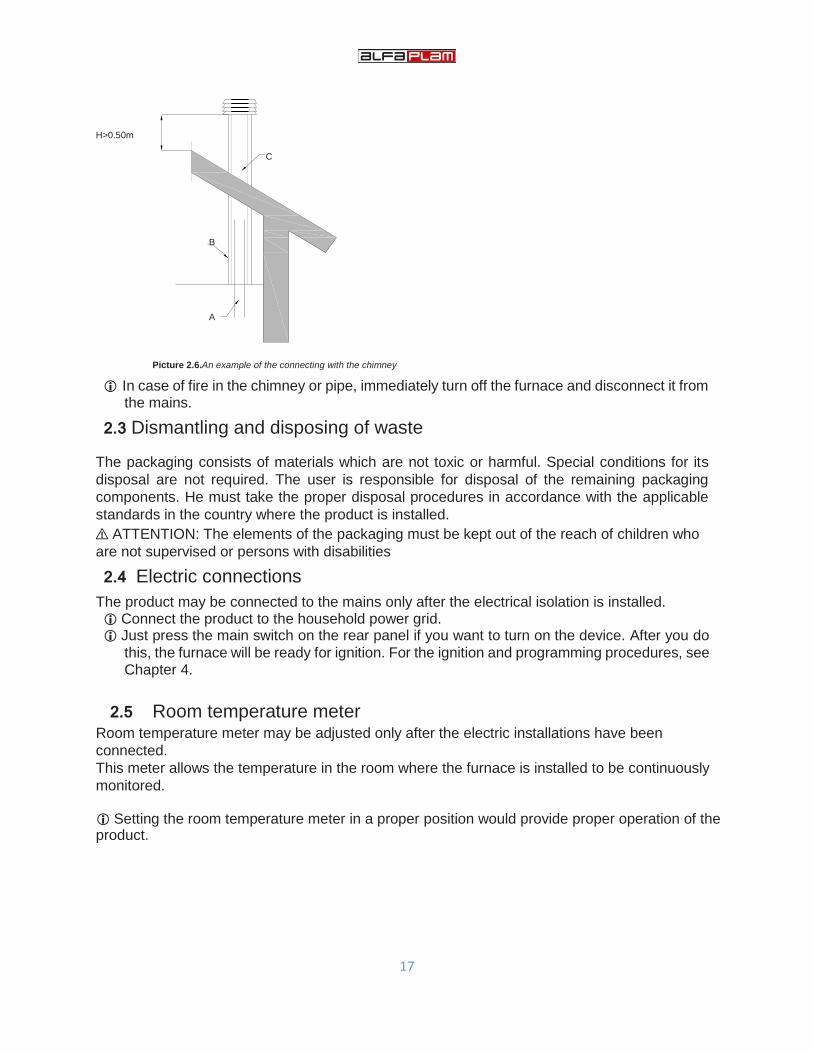
4.6.2 Pellet feeding calibration management The user has the possibility to calibrate the dosing of pellets in the User menu 1. Calibration range from -7 ÷ 7. 1=5%. Each calibration of the pellet dosing is applied percentually to all work powers. E.g. if set to -1 then the pellet dosing would decrease by 5% in all operating modes (Power 1 - 5).
Example
Before calibration
Power 1 = 2.0
Power 2 = 3.0
Power 3 = 4.0
Power 4 = 5.0 Power 5 = 6.0
Step = -1 Power 1 = 1.9
Power 2 = 2.85
Power 3 = 3.8
Power 4 = 4.75
Power 5 = 5.7
Never calibrate the pellet dosing without consultations with the repair shop.
4.6.3 Managing the correction of the flue gas motor The user has the possibility to calibrate the speed of flue gases motor in the User menu 1. Calibration range from -7 ÷ 7. 1=5%. Each calibration is applied percentually to all work powers. E.g. if set to 3 then the flue gas motor speed would increase by 15% (3x5%) in all operating modes (Power 1 - 5).
Example Before calibration
Power 1 = 1000
Power 2 = 1200
Power 3 = 1400
Power 4 = 1600
Power 5 = 1800
Step = +3 Power 1 = 1150
Power 2 = 1380
Power 3 = 1610
Power 4 = 1840
Power 4 = 2070
Never calibrate the speed of flue gas motor without consultations with the repair shop.
4.6.4 Safety thermostat In case the temperature of the pellets in the tank reaches a value greater than 90°C, a safety thermostat is activated in order to prevent the ignition of the pellets in the tank. The system moves to the blockage mode of work and the alarm message Er01 appears.
4.6.5 Periodical cleaning of the furnace
When the system is in stable condition, after a specified time interval (every 45 minutes), the system automatically performs periodic cleaning for 30 seconds. During the periodic cleaning, the flue gas motor works with increased intensity and the dosing of pellets stops.
4.6.6 Shutting down during the ignition phase
When the system is turned off during the ignition phase (after the preheater phase) through an external device or internal Chrono device, the system goes into shutdown phase when it enters the mode of operation at the end of ignition. The display will show the message Block ignition. If an error occurs, the system immediately shuts down; If the P2 button is pressed, it is possible to immediately introduce the system in the shut down or start up condition.
4.7 Potential problems and solutions
Display message
Description Potential causes Error reset Potential solutions for the
cause of the alarm
Er01
Activation of the safety thermostat
High temperature inside the furnace
Wait until the oven has cooled and then unscrew the plastic cap on the thermostat and press the reset button
Check the heat outputs i.e. that there are no obstacles for the passage of hot air
Excessive temperature in the room where the furnace is installed
Contact the repair shop

29
Faulty thermostat
Er02
Activation of the safety pressure switches
Obstruction of the flue gas outlet
Press and hold P2 button for more than 3 seconds
Check the cleanliness of flue pipes and chimneys
Faulty chimney installations
Contact the repair shop Faulty pressure switch
Er03
Shutting off due to too low flue gas temperature.
Bad combustion (the amount of pellet in the burning unit is too low or too high)
Wait for the furnace to extinguish and then press and hold P2 button for more than 3 seconds
Check the size of the pellet
Check the cleanliness of the furnace chamber
Pellet tank empty Check the condition of the flue ducts
Faulty flue gas probe Contact the repair shop
Er05
Shutting off due to too high flue gas temperature.
Flue gas temperature exceeds the limit
Wait for the furnace to extinguish and then press and hold P2 button for more than 3 seconds
Insufficient heat transfer - call the repair shop Obstruction of the flue
gas outlet Check the cleanliness of the flue duct and chimney
Faulty flue gas probe
Er07
Encoder error
Encoder signal missing
Wait for the furnace to extinguish and then press and hold P2 button for more than 3 seconds
Contact the repair shop
Er08
Encoder error
Flue gas motor does not respond
Wait for the furnace to extinguish and then press and hold P2 button for more than 3 seconds
Contact the repair shop
The flue gas motor works at the speed different from the set speed
Er11
Clock error
Problems with the internal clock
Press and hold P2 button for more than 3 seconds
Check the accuracy of the set time
Insufficient capacity of the internal battery
Check the accuracy of programming in the Chrono mode of work
Contact the repair shop
Er12
Failed ignition of the furnace
Error during the ignition of the furnace
Wait for the furnace to extinguish and then press and hold P2 button for more than 3 seconds
Check the condition and the quality of the pellet being used
During the entire duration of the ignition phase, the adequate temperature of flue gases was not achieved.
Check the flue pipes for dirtiness and draft
Faulty flue gas probe
Contact the repair shop

30
Er15
Interruption of power supply
The power outage during the operative work of the furnace
Press and hold P2 button for more than 3 seconds
Check the functionality of the system and installations
Contact the repair shop
Er16
Error in communication between the electronics and display
Display cable disconnected
Press and hold P2 button for more than 3 seconds
Check the cable and the display cable connectors Display cable connector
damaged. Contact the repair shop
Er17
Error on the primary air flow meter
The primary air flow meter does not adjust the work of the furnace
The furnace continues to work without adjusting of the primary air For the reactivation of the flow meter, shut the furnace down. Wait for the furnace to extinguish and then press and hold P2 button for more than 3 seconds
Check the cleanliness of the pipe for primary air intake
Check the flue pipes and chimneys for dirtiness and draft
Contact the repair shop
Er39
Primary air flow meter sensor damaged.
Faulty sensor
The furnace continues to work without adjusting of the primary air
Contact the repair shop
Er41
Minimal primary air flow during the check phase is not achieved
The presence of some large obstacle or debris in the pipe for entry of primary air
Wait for the furnace to extinguish and then press and hold P2 button for more than 3 seconds
Check and clean the primary air intake pipe
Check the flue pipes and chimneys for dirtiness and draft
Obstruction of the flue gas outlet
Doors not closed during the ignition phase
Check whether the doors can be well closed
Contact the repair shop
Er42
The flow of primary air exceeds the maximal permitted value
Inlet air quantity too high
Wait for the furnace to extinguish and then press and hold P2 button for more than 3 seconds
Check the pipe for primary air intake
Check the flue pipes and chimneys for dirtiness and draft
Contact the repair shop
NOTE: If the corrective action does not remove the direct cause of the alarm, CONTACT ALFA PLAM CALL CENTRE.

31
1 2
3
5 STOVE MAINTENANCE
5.1 Routine maintenance
With routine cleaning and maintenance, the furnace will keep its heating and functional
characteristics over time.
⚠ ATTENTION: Cleaning procedures described below must be carried out only when the stove
is completely cold and disconnected from the power supply (so that the power plug is
unplugged).
5.1.1 CLEANING OF THE DISPLAY AND PARTS OF THE EXTERNAL INSULATION
Cleaning should be done with a soft dry cloth without any detergents or chemicals.
5.1.2 CLEANING OF THE CERAMIC GLASS
This should be performed whenever necessary.
The frequency of cleaning of the ceramic glass depends on the quality and type of fuel, as well as
on the ways of use of the furnace.
To thoroughly clean the glass ceramic, we recommend a cloth sprayed with a small amount of a
suitable detergent to be used to remove the dirt (see Figures 1 and 2).
Never spray detergent or any other liquid cleaner directly on ceramic glass (see Figure 3).
NEVER use abrasive sponges or similar products to clean the ceramic glass, as they may
cause irreparable damage.
⚠ ATTENTION: Make sure to seal the doors each time you open them to clean the ceramic glass.

32
5.1.3 ROUTINE MAINTENANCE, ACTIVITY TYPE 1
These activities should be done at least twice a week, depending on conditions of use.
After some time of using the furnace, the user may specify the appropriate frequency of cleaning
and maintenance of the furnace.
⚠ ATTENTION: Each cleaning activity has to be performed when the furnace is completely cold
and disconnected from the power supply (with the cable pulled out from the socket).
Number of maintenance activities is increasing in proportion to the intensity of the use of the
furnace.
⚠ ATTENTION: Be sure that ash is completely cold before you start cleaning. Once you
conclude that the ash is cold, you may vacuum it with a vacuum cleaner. Periodic maintenance Type 1 shall be performed in accordance with the following procedure:
1. Slowly open the furnace door so that the accumulated ash does not fly around due to the fast
movement.
2. Remove the mesh.
3. Remove the pellet protection and the burner.
4. Using a vacuum cleaner and a wire brush (or other sufficiently abrasive material) to clean the
ash and other debris from the burner, because these impurities prevent the passage of air.

33
5. Remove the ash tray by hand and empty it.
6. Use a vacuum of sufficient power (1000-1300W) to remove all the ash accumulated in the
combustion chamber, the ash pan and the door.
After you've finished cleaning, re-assemble all the elements in the reverse order from the order
in which you removed them.
5.2 Special maintenance
Activities of special cleaning and maintenance (types 2 and 3) help the furnace to keep its
heating and functional characteristics for a longer time.
To ensure that the maintenance of the furnace is not in vain, it is necessary to maintain a system
for extraction of smoke just as thoroughly.
5.2.1 SPECIAL MAINTENANCE ACTIVITIES TYPE 2
In addition to maintenance activities Type 1, maintenance activities Type 2 must be carried out
at about 350-400 hours, or else after about 500~600 kg of fuel.
⚠ ATTENTION: Each cleaning activity has to be performed when the furnace is completely
cold and disconnected from the power supply (with the cable pulled out from the socket).
⚠ ATTENTION: Be sure that ash is completely cold before you start cleaning. Once you observe
that ash is cold, you may vacuum it with a vacuum cleaner. The activities of periodic maintenance Type 2 shall be performed in accordance with the
following procedure:
1. Unscrew and remove the 4 M6 screws that hold the chamber cover for collecting of dust on
the heat exchanger.

34
2. Remove the cover from the dust chamber on the heat exchanger.
3. Remove the soot with a shovel, and use the vacuum cleaner to pick up the remaining soot
and ashes from the dust chamber on the heat exchanger. To properly remove the soot and
ash on CSA9 model, it is also necessary to remove the component of the "kit for smoke
extraction", located in the section where the container for the collection of dust on the heat
exchanger is located.
After you've finished cleaning, re-assemble all the elements in the reverse order from the order
in which you removed them.
5.2.2 SPECIAL MAINTENANCE ACTIVITIES TYPE 3
These activities should be carried out at the end of the season, along with the activities of routine
maintenance Type 1 and special maintenance Type 2.
Smoke motor

35
These activities of special maintenance are used to clean the smoke motor and its casing, as
well as to carry out a thorough cleaning of the lower part of the heat exchanger.
⚠ ATTENTION: These activities have to be performed by authorised personnel.
⚠ ATTENTION: Each cleaning activity has to be performed when the furnace is completely cold
and disconnected from the power supply (with the cable pulled out from the socket).
⚠ ATTENTION: Be sure that ash is completely cold before you start cleaning. Once you observe
that ash is cold, you may vacuum it with a vacuum cleaner.
5.2.3 CHECKING OF SEALS
In conducting the activities of special maintenance at the end of the season, make sure that the
authorised person also checks the door seals and the components that can be removed. These
parts usually must be replaced every three years, depending on the type of furnace, the intensity
of use, etc. Seals must be elastic at touch and must be replaced if they become totally glassy.
5.2.4 CLEANING OF THE EXHAUST DUCT
It is recommended to clean the smoke duct and the pipe on the regular basis.
These cleaning activities shall be performed at least annually or more frequently if the unit is
used on a daily basis, or if the characteristics of the fuel used differ from the characteristics listed
in section 1.7.
It is recommended that these activities are done by professional staff; ask for their contact details
from a reseller. The intervention of the authorised person can be an effective and economical
way to protect the system from corrosion and to ensure its efficient operation.
For the houses that are not occupied throughout the year, it is recommended to review the pipe
and chimney at the beginning of the heating season, even if they have already been cleaned,
to make sure that there are no obstacles, such as bee nests, bird nests or other similar
elements.
5.3 Withdrawal from use
It is recommended that you leave the stove to burn all the wood pellets from the tank before
you start with routine and special maintenance and putting the furnace out of service at the end
of the heating season.
⚠ ATTENTION: When the heating season is off, the power cord of the furnace must be
disconnected from the socket.
6. WARRANTY CONDITIONS
6.1. THE PERIOD OF GUARANTEED SERVICE
This implies the period during which we guarantee the service, tools and spare parts, starting with the date
of purchase of the device.
The duration of the guaranteed service is in accordance with the applicable laws and regulations.
In case of change of model and design of the device, the deadline for replacement of parts that changed
the design is within the legal deadline.
After this period, the replaced parts are provided with the new design.
6.2. WARRANTY CONDITIONS

36
Product warranty is valid during the period prescribed by the law.
The warranty does not apply to glass, ceramic and physical damage caused after purchase.
THE MANUFACTURER RESERVES THE RIGHT TO MAKE ANY CHANGES.
The device under warranty will function properly only if used in accordance with these instructions for
installation and use.
The warranty expires if it is established that:
- Connecting the product or repair performed by an unauthorised person, or if non-original parts were used;
- If the device was not used properly in accordance with this instruction;
- If a mechanical damage occurred during the use of the device;
- If the repairs were performed by an unauthorised person;
- If the device was used for commercial purposes;
- If the damage occurred during transport after the sale of the device;
- If the failure was due to improper installation, improper maintenance or mechanical damage caused by the
customer;
- If the malfunction was the result of too high or too high voltage, as well as of force majeure.
Defects on the device may be removed even after the expiration of the warranty using the original
replacement parts for which we also provide a warrantee under the same conditions.
This warranty does not exclude or affect the rights of the consumers in connection with the conformity of
the goods in accordance with the legal regulations. If the supplied product is not in conformity with the
contract, the consumer has the right to require the seller to remove such inconformity without
compensation through repair or replacement of the product in accordance with the applicable legislation.
CONTENTS
1. Introduction pg. 2
1.1 Product serial number pg. 3
1.2 Materials pg. 3
1.3 Certification pg.3
1.4 Dimensions pg.4
1.5 Technical characteristics pg.6
1.6 Fuel characteristics pg.6
1.7 Safety recommendations pg.8
1.8 General recommendations pg.9
1.9 Safety device pg.9
1.10 Environment for the use of the product pg.10
2. Installation pg.11
2.1 Placing of the device pg.11
2.2 Pipe characteristics pg.13

37
2.3 Dismantling and disposing of waste pg.16
2.4 Electric connections pg.16
2.5 Room temperature meter pg.16
3. Use of the product pg.17
3.1 Necessary controls and checks for first ignition pg.17
3.2 Fuel feed pg.17
4. Furnace management systems pg.18
4.1 Electric wiring scheme pg.18
4.2 The control panel (display): use and functions pg.19
4.3 User menu 1 pg.21
4.4 User menu 2. pg.24
4.5 Ignition of the furnace and the functional states. pg.25
4.6 Other functions pg.26
4.7 Potential problems and solutions pg.27
5. Furnace maintenance pg.30
5.1 Routine maintenance pg.30
5.2 Special maintenance pg.32
5.3 Withdrawal from use pg.34
6. Warranty statement…………………………………….………………………pg.34


![RAUBIOXON PLUS ANd RAUBIOfLeX AeRAtOR SyStemS · RAUBIOXON PLUS ANd RAUBIOfLeX AeRAtOR SyStemS tABLe Of CONteNtS ... Shore hardness 60 ± 5 [Shore A] DIN 53505 Tensile strength ≥](https://static.fdocuments.us/doc/165x107/5b27dc467f8b9a104d8b4dfe/raubioxon-plus-and-raubioflex-aerator-systems-raubioxon-plus-and-raubioflex.jpg)