EN 302 217-2-1 - V1.1.3 - Fixed Radio Systems ... EN 302 217-2-1 V1.1.3 (2004-12) European Standard...
55
ETSI EN 302 217-2-1 V1.1.3 (2004-12) European Standard (Telecommunications series) Fixed Radio Systems; Characteristics and requirements for point-to-point equipment and antennas; Part 2-1: System-dependent requirements for digital systems operating in frequency bands where frequency co-ordination is applied
-
Upload
truongliem -
Category
Documents
-
view
235 -
download
0
Transcript of EN 302 217-2-1 - V1.1.3 - Fixed Radio Systems ... EN 302 217-2-1 V1.1.3 (2004-12) European Standard...

ETSI EN 302 217-2-1 V1.1.3 (2004-12)
European Standard (Telecommunications series)
Fixed Radio Systems;Characteristics and requirements for
point-to-point equipment and antennas;Part 2-1: System-dependent requirements
for digital systems operating in frequency bandswhere frequency co-ordination is applied

ETSI
ETSI EN 302 217-2-1 V1.1.3 (2004-12) 2
Reference DEN/TM-04131-2-1
Keywords DFRS, digital, DRRS, FWA, point-to-point, radio,
transmission
ETSI
650 Route des Lucioles F-06921 Sophia Antipolis Cedex - FRANCE
Tel.: +33 4 92 94 42 00 Fax: +33 4 93 65 47 16
Siret N° 348 623 562 00017 - NAF 742 C
Association à but non lucratif enregistrée à la Sous-Préfecture de Grasse (06) N° 7803/88
Important notice
Individual copies of the present document can be downloaded from: http://www.etsi.org
The present document may be made available in more than one electronic version or in print. In any case of existing or perceived difference in contents between such versions, the reference version is the Portable Document Format (PDF).
In case of dispute, the reference shall be the printing on ETSI printers of the PDF version kept on a specific network drive within ETSI Secretariat.
Users of the present document should be aware that the document may be subject to revision or change of status. Information on the current status of this and other ETSI documents is available at
http://portal.etsi.org/tb/status/status.asp
If you find errors in the present document, please send your comment to one of the following services: http://portal.etsi.org/chaircor/ETSI_support.asp
Copyright Notification
No part may be reproduced except as authorized by written permission. The copyright and the foregoing restriction extend to reproduction in all media.
© European Telecommunications Standards Institute 2004.
All rights reserved.
DECTTM, PLUGTESTSTM and UMTSTM are Trade Marks of ETSI registered for the benefit of its Members. TIPHONTM and the TIPHON logo are Trade Marks currently being registered by ETSI for the benefit of its Members. 3GPPTM is a Trade Mark of ETSI registered for the benefit of its Members and of the 3GPP Organizational Partners.
ETSI
ETSI EN 302 217-2-1 V1.1.3 (2004-12) 3
Contents
Intellectual Property Rights ................................................................................................................................6
Foreword.............................................................................................................................................................6
Introduction ........................................................................................................................................................6
1 Scope ........................................................................................................................................................7
2 References ................................................................................................................................................8
3 Definitions, symbols and abbreviations .................................................................................................10 3.1 Definitions........................................................................................................................................................10 3.2 Symbols............................................................................................................................................................10 3.3 Abbreviations ...................................................................................................................................................10
4 General characteristics ...........................................................................................................................10 4.1 Frequency bands and channel arrangements ....................................................................................................10 4.2 Special compatibility requirements between systems ......................................................................................11 4.3 Transmission capacity and spectral efficiency .................................................................................................11
5 Main requirements..................................................................................................................................12 5.1 Transmitter characteristics................................................................................................................................12 5.1.1 Transmitter power.......................................................................................................................................12 5.1.2 Transmitter power and frequency control ...................................................................................................12 5.1.2.1 Transmitter power control (ATPC and RTPC) .....................................................................................12 5.1.2.1.1 Automatic Transmitter Power Control (ATPC)...............................................................................12 5.1.2.1.2 Remote Transmitter Power Control (RTPC) ...................................................................................13 5.1.2.2 Remote Frequency Control (RFC) ........................................................................................................13 5.1.3 Transmitter output power tolerance ............................................................................................................13 5.1.4 Radio Frequency (RF) spectrum mask........................................................................................................13 5.1.5 Discrete CW components exceeding the spectrum mask limit ...................................................................14 5.1.5.1 Discrete CW components at the symbol rate ........................................................................................14 5.1.5.2 Other discrete CW components exceeding the spectrum mask limit ....................................................14 5.1.6 Spurious emissions - external .....................................................................................................................14 5.1.7 Radio frequency tolerance ..........................................................................................................................14 5.2 Receiver characteristics ....................................................................................................................................15 5.2.1 Spurious emissions-external .......................................................................................................................15 5.3 System performance without diversity .............................................................................................................15 5.3.1 BER as a function of receiver signal level ..................................................................................................15 5.3.2 Interference sensitivity................................................................................................................................15 5.3.2.1 Co-channel "external" interference sensitivity ......................................................................................15 5.3.2.2 Adjacent channel interference sensitivity..............................................................................................15 5.3.2.3 CW spurious interference......................................................................................................................15
6 Complementary requirements ................................................................................................................16 6.1 Branching/feeder requirements ........................................................................................................................16 6.1.1 Waveguide flanges (or other connectors) ...................................................................................................16 6.1.2 Return loss at equipment antenna port (C/C' reference point) ....................................................................17 6.2 Intermodulation products .................................................................................................................................17 6.3 Transmitter characteristics................................................................................................................................17 6.3.1 Spurious emissions - internal ......................................................................................................................17 6.4 Receiver characteristics ....................................................................................................................................18 6.4.1 Input level range .........................................................................................................................................18 6.4.2 Spurious emissions - internal ......................................................................................................................19 6.4.3 Image rejection ...........................................................................................................................................20 6.4.4 Innermost channel selectivity .....................................................................................................................20 6.5 System performance without diversity .............................................................................................................20 6.5.1 Equipment Residual BER (RBER) .............................................................................................................20 6.5.2 Interference sensitivity for CCDP with XPIC operation.............................................................................21 6.5.2.1 Co-channel "internal" interference sensitivity in flat fading conditions................................................22

ETSI
ETSI EN 302 217-2-1 V1.1.3 (2004-12) 4
6.5.2.2 Co-channel "internal" interference sensitivity under dispersive fading conditions...............................22 6.5.3 Distortion sensitivity...................................................................................................................................22 6.6 System characteristics with diversity ...............................................................................................................23 6.6.1 Differential delay compensation .................................................................................................................23 6.6.2 BER performance .......................................................................................................................................23
Annex A (normative): Frequency bands from 1,4 GHz to 2,7 GHz ................................................24
A.0 Introduction ............................................................................................................................................24
Annex B (normative): Frequency bands from 3 GHz to 11 GHz (channel separation up to 30 MHz) ..........................................................................................................25
B.0 Introduction ............................................................................................................................................25
B.1 System B.1 (2 - 2 × 34 Mbit/s; STM-0 - 2 × STM-0/ 3 GHz - 11 GHz/1,75 MHz - 29,65 MHz).........26 B.1.1 Distortion sensitivity ........................................................................................................................................26
B.2 System B.2 (STM-1 / 3 GHz - 8 GHz/about 30 MHz ACAP) ...............................................................26 B.2.1 Radio Frequency (RF) spectrum mask .............................................................................................................26 B.2.2 Receiver innermost channel selectivity ............................................................................................................29
B.3 System B.3 (2 × STM-1 / 3 GHz -8 GHz / about 30 MHz CCDP) ........................................................29 B.3.1 Radio Frequency (RF) spectrum mask .............................................................................................................29 B.3.2 Innermost channel selectivity ...........................................................................................................................31 B.3.3 Distortion sensitivity ........................................................................................................................................33
Annex C (normative): Frequency bands from 3 GHz to 11 GHz (channel separation 40 MHz) ...............................................................................................................34
C.0 Introduction ............................................................................................................................................34
C.1 System C.1 (2 × STM-1 / 3-11 GHz / 40 MHz - CCDP) .......................................................................35 C.1.1 Radio Frequency (RF) spectrum mask .............................................................................................................35 C.1.2 Distortion sensitivity ........................................................................................................................................36
C.2 System C.2 (2 × STM-1 / 3 GHz -11 GHz / 40 MHz - ACCP)..............................................................36 C.2.1 Radio Frequency (RF) spectrum mask .............................................................................................................36 C.2.2 Receiver input level range ................................................................................................................................37
C.3 System C.3 (4 × STM-1/3 GHz -11 GHz/40 MHz - CCDP)..................................................................37 C.3.1 Transmitter Radio Frequency (RF) spectrum mask..........................................................................................37 C.3.2 Receiver input level range ................................................................................................................................38 C.3.3 Distortion sensitivity ........................................................................................................................................38
Annex D (normative): Frequency bands 13 GHz, 15 GHz and 18 GHz..........................................39
D.0 Introduction ............................................................................................................................................39
D.1 System D.1 (2 / 2 × 34 Mbit/s / 13 GHz - 15 GHz - 18 GHz / 1,75 MHz / 28 MHz ) ...........................40 D.1.1 Distortion sensitivity ........................................................................................................................................40
D.2 System D.2 (sub STM-0 / 18 GHz / 3,5 MHz).......................................................................................40
D.3 System D.3 (STM-0 / 13 GHz -15 GHz -18 GHz / 28 MHz ACCP-14 MHz ACAP) ...........................41
D.4 System D.4 (STM-0 / 13 GHz -15 GHz - 18 GHz / 14 MHz ACCP) ....................................................41 D.4.1 Distortion sensitivity ........................................................................................................................................41
D.5 System D.5 (STM-1 / 13 GHz - 15 GHz / about 30 MHz ACAP).........................................................41
D.6 System D.6 (2 × STM-1 / 13 GHz - 15 GHz / about 30 MHz CCDP)...................................................41
D.7 System D.7 (STM-1 / 18 GHz / 55 MHz - 27,5 MHz)...........................................................................41 D.7.1 RF spectrum mask ............................................................................................................................................41 D.7.1.1 Class 4 equipment.......................................................................................................................................41 D.7.1.2 Class 5B equipment ....................................................................................................................................42 D.7.2 Distortion sensitivity ........................................................................................................................................43

ETSI
ETSI EN 302 217-2-1 V1.1.3 (2004-12) 5
D.8 System D.8 (2 × STM-1 and STM-4 / 15 GHz - 18 GHz / 55 MHz - 56 MHz) ....................................43
Annex E (normative): Frequency bands from 23 GHz to 55 GHz ..................................................44
E.0 Introduction ............................................................................................................................................44
E.1 Systems E.1, E.2 and E.3: Transmitter spectrum mask for class 5B equipment ....................................45
Annex F (normative): Transmission of packet data and combinations of other signals in bands from 3 GHz to 55 GHz .......................................................................46
F.1 Introduction ............................................................................................................................................46
F.2 General characteristics ...........................................................................................................................46 F.2.1 Frequency characteristics and channel arrangements.......................................................................................46 F.2.2 Transmission capacities and equipment assessment.........................................................................................46
Annex G (informative): Additional information..................................................................................47
G.1 Residual Bit Error Ratio (RBER) and Frame Error Ratio (RFER) ........................................................47
G.2 Measurement test set for XPI characteristics .........................................................................................48
G.3 Differential delay compensation range...................................................................................................49
G.4 FER/BER equivalence and FER performance measurement equipment settings (example) .................49 G.4.1 FER/BER equivalence......................................................................................................................................49 G.4.2 FER equipment settings and measurement techniques (example)....................................................................50
G.5 Automatic Transmitter Power Control (ATPC) .....................................................................................50
Annex H (informative): Mitigation techniques referred in ERC/DEC(00)07 (18 GHz band).........52
Annex I (informative): Bibliography...................................................................................................53
History ..............................................................................................................................................................55
ETSI
ETSI EN 302 217-2-1 V1.1.3 (2004-12) 6
Intellectual Property Rights IPRs essential or potentially essential to the present document may have been declared to ETSI. The information pertaining to these essential IPRs, if any, is publicly available for ETSI members and non-members, and can be found in ETSI SR 000 314: "Intellectual Property Rights (IPRs); Essential, or potentially Essential, IPRs notified to ETSI in respect of ETSI standards", which is available from the ETSI Secretariat. Latest updates are available on the ETSI Web server (http://webapp.etsi.org/IPR/home.asp).
Pursuant to the ETSI IPR Policy, no investigation, including IPR searches, has been carried out by ETSI. No guarantee can be given as to the existence of other IPRs not referenced in ETSI SR 000 314 (or the updates on the ETSI Web server) which are, or may be, or may become, essential to the present document.
Foreword This European Standard (Telecommunications series) has been produced by ETSI Technical Committee Transmission and Multiplexing (TM).
The present document is part 2-1 of a multi-part deliverable covering the Fixed Radio Systems; Characteristics and requirements for point-to-point equipment and antennas, as identified below:
Part 1: "Overview and system-independent common characteristics";
Part 2-1: "System-dependent requirements for digital systems operating in frequency bands where frequency co-ordination is applied";
Part 2-2 "Harmonized EN covering essential requirements of Article 3.2 of R&TTE Directive for digital systems operating in frequency bands where frequency co-ordination is applied";
Part 3: "Harmonized EN covering essential requirements of Article 3.2 of R&TTE Directive for equipment operating in frequency bands where no frequency co-ordination is applied";
Part 4-1: "System-dependent requirements for antennas";
Part 4-2: "Harmonized EN covering essential requirements of Article 3.2 of R&TTE Directive for antennas".
National transposition dates
Date of adoption of this EN: 19 November 2004
Date of latest announcement of this EN (doa): 28 February 2005
Date of latest publication of new National Standard or endorsement of this EN (dop/e):
31 August 2005
Date of withdrawal of any conflicting National Standard (dow): 28 February 2007
Introduction The introduction of EN 302 217-1 applies.

ETSI
ETSI EN 302 217-2-1 V1.1.3 (2004-12) 7
1 Scope The present document summarizes all system-dependent requirements for Point-to-Point (P-P) equipment in applications deployed in bands where frequency co-ordination is generally applied. These requirements are introduced in two different clauses sub-sets:
• Main requirements are requirements that are also related to the "essential requirements" under article 3.2 of the R&TTE Directive [1] and further detailed in EN 302 217-2-2 [16].
• Complementary requirements are requirements that are not related to essential requirements under article 3.2 of the R&TTE Directive [1]. Nevertheless they are considered having been commonly agreed for proper system operation and deployment when specific deployment conditions or compatibility requirements are present. Compliance to all or some of these requirements is made on a voluntary basis.
Description and limits for parameters relevant to essential requirements under article 3.2 of R&TTE Directive [1] are given in EN 302 217-2-2 [16].
For other system-dependent parameters where standardization is required but that do not affect the R&TTE Directive "essential requirements" mentioned above, description and limits are detailed in the present document in the annexes A to G, subdivided by frequency band or specific applications.
The present document deals with Radio Frequency (RF) and base-band equipment characteristics; antenna system requirements are covered in EN 302 217-4-1 (see bibliography) and EN 302 217-4-2 (see bibliography).
The present document does not cover test procedures and test conditions which are set out in EN 301 126-1 [14].
As the maximum transmission rate in a given bandwidth depends on system spectral efficiency, different equipment classes are defined:
• Class 1: equipment spectral efficiency based on typical 2-states modulation scheme (e.g. 2-FSK, 2-PSK or equivalent);
• Class 2: equipment spectral efficiency based on typical 4-states modulation scheme (e.g. 4-FSK, 4-QAM, or equivalent);
• Class 3: equipment spectral efficiency based on typical 8-states modulation scheme (e.g. 8-PSK, or equivalent);
NOTE: It is also noted that, in this class, for design commonality with other efficiency classes, the 16 QAM format is popular).
• Class 4: equipment spectral efficiency based on typical 16-states or 32-states modulation scheme (e.g. 16-QAM or 32-QAM, or equivalent);
• Class 5A: equipment spectral efficiency based on typical 64-states or 128-states modulation scheme (e.g. 64-QAM or 128-QAM, or equivalent), for cross-polar adjacent channel (ACAP) operation;
• Class 5B: equipment spectral efficiency based on typical 64-states or 128-states modulation scheme (e.g. 64-QAM or 128-QAM, or equivalent), for co-polar adjacent channel (ACCP) and frequency reuse through CCDP operation;
• Class 6A: equipment spectral efficiency based on typical 256-states or 512-states modulation scheme (e.g. 256-QAM or 512-QAM, or equivalent), for cross-polar adjacent channel (ACAP) operation;
• Class 6B: equipment spectral efficiency based on typical 256-states or 512-states modulation scheme (e.g. 256-QAM or 512-QAM, or equivalent), for co-polar adjacent channel (ACCP) and frequency reuse through CCDP operation.
The above classes are indicative only and do not imply any constraint to the actual modulation format, provided that all the requirements in the relevant parts of this EN 302 217 series are met.
ETSI
ETSI EN 302 217-2-1 V1.1.3 (2004-12) 8
In some cases, where within the same spectral efficiency class there are different applications, (e.g. for multi-channel trunk or single channel operation), that justify different radio frequency parameters, two different equipment "types" (e.g. type 1 and 2) are provided.
Guidance on the definition of radio parameters relevant to the essential requirements under article 3.2 of R&TTE Directive [1] for DFRS may be found in TR 101 506 (see bibliography).
Technical background for most of the parameters and requirements referred to in this EN 302 217 series may be found in TR 101 036-1 (see bibliography).
2 References The following documents contain provisions which, through reference in this text, constitute provisions of the present document.
• References are either specific (identified by date of publication and/or edition number or version number) or non-specific.
• For a specific reference, subsequent revisions do not apply.
• For a non-specific reference, the latest version applies.
Referenced documents which are not found to be publicly available in the expected location might be found at http://docbox.etsi.org/Reference.
[1] Directive 1999/5/EC of the European Parliament and of the Council of 9 March 1999 on radio equipment and telecommunications terminal equipment and the mutual recognition of their conformity (R&TTE Directive).
[2] CENELEC EN 122150: "Sectional Specification: Radio frequency coaxial connectors - Series EIA flange".
[3] ERC/DEC(00)07: "ERC Decision of 19 October 2000 on the shared use of the band 17.7 - 19.7 GHz by the fixed service and Earth stations of the fixed-satellite service (space to Earth)".
[4] ETSI EN 300 019-1-0: "Environmental Engineering (EE); Environmental conditions and environmental tests for telecommunications equipment; Part 1-0: Classification of environmental conditions; Introduction".
[5] ETSI EN 300 019-1-1: "Environmental Engineering (EE); Environmental conditions and environmental tests for telecommunications equipment; Part 1-1: Classification of environmental conditions; Storage".
[6] ETSI EN 300 019-1-2: "Environmental Engineering (EE); Environmental conditions and environmental tests for telecommunications equipment; Part 1-2: Classification of environmental conditions; Transportation".
[7] ETSI EN 300 019-1-3: "Environmental Engineering (EE); Environmental conditions and environmental tests for telecommunications equipment; Part 1-3: Classification of environmental conditions; Stationary use at weatherprotected locations".
[8] ETSI EN 300 019-1-4: "Environmental Engineering (EE); Environmental conditions and environmental tests for telecommunications equipment; Part 1-4: Classification of environmental conditions; Stationary use at non-weatherprotected locations".
[9] ETSI EN 300 019-2-0: "Environmental Engineering (EE); Environmental conditions and environmental tests for telecommunications equipment; Part 2-0: Specification of environmental tests; Introduction".
[10] ETSI EN 300 019-2-1: "Environmental Engineering (EE); Environmental conditions and environmental tests for telecommunications equipment; Part 2-1: Specification of environmental tests; Storage".

ETSI
ETSI EN 302 217-2-1 V1.1.3 (2004-12) 9
[11] ETSI EN 300 019-2-2: "Equipment Engineering (EE); Environmental conditions and environmental tests for telecommunications equipment; Part 2-2: Specification of environmental tests; Transportation".
[12] ETSI EN 300 019-2-3: "Environmental Engineering (EE); Environmental conditions and environmental tests for telecommunications equipment; Part 2-3: Specification of environmental tests; Stationary use at weatherprotected locations".
[13] ETSI EN 300 019-2-4: "Environmental Engineering (EE); Environmental conditions and environmental tests for telecommunications equipment; Part 2-4: Specification of environmental tests; Stationary use at non-weatherprotected locations".
[14] ETSI EN 301 126-1: "Fixed Radio Systems; Conformance testing; Part 1: Point-to-Point equipment - Definitions, general requirements and test procedures".
[15] ETSI EN 302 217-1: "Fixed Radio Systems; Characteristics and requirements for point-to-point equipment and antennas; Part 1: Overview and system-independent common characteristics".
[16] ETSI EN 302 217-2-2: "Fixed Radio Systems; Characteristics and requirements for point-to-point equipment and antennas; Part 2-2: Harmonized EN covering essential requirements of Article 3.2 of R&TTE Directive for digital systems operating in frequency bands where frequency co-ordination is applied".
[17] IEC 60153-2: "Hollow metallic waveguides. Part 2: Relevant specifications for ordinary rectangular waveguides".
[18] IEC 60154-2: "Flanges for waveguides. Part 2: Relevant specifications for flanges for ordinary rectangular waveguides".
[19] IEC 60169: "Radio-frequency connectors. Part 1: General requirements and measuring methods".
[20] IEC 60339 (all parts): "General purpose rigid coaxial transmission lines and their associated flange connectors".
[21] IEC 60835-2-4: "Methods of measurement for equipment used in digital microwave radio transmission systems - Part 2: Measurements on terrestrial radio-relay systems - Section 4: Transmitter/receiver including modulator/demodulator".
[22] IEC 60835-2-8: "Methods of measurement for equipment used in digital microwave radio transmission systems - Part 2: Measurements on terrestrial radio-relay systems - Section 8: Adaptive equalizer".
[23] IEEE 802.3-2002: "IEEE Standard for Information technology - Telecommunications and information exchange between systems - Local and metropolitan area networks - Specific requirements - Part 3: Carrier Sense Multiple Access with Collision Detection (CSMA/CD) Access Method and Physical Layer Specifications".
[24] IEEE 1802.3-2001: "IEEE Conformance Test Methodology for IEEE Standards for Local and Metropolitan Area Networks-Specific Requirements-Part 3: Carrier Sense Multiple Access with Collision Detection (CSMA/CD) Access Method and Physical Layer Specifications".
[25] ITU-T Recommendation G.708: "Sub STM-0 network node interface for the synchronous digital hierarchy (SDH)".
[26] ITU-T Recommendation O.151: "Error performance measuring equipment operating at the primary rate and above".
[27] ITU-T Recommendation O.181: "Equipment to assess error performance on STM-N interfaces".
[28] ITU-T Recommendation O.191: "Equipment to measure the cell transfer performance of ATM connections".

ETSI
ETSI EN 302 217-2-1 V1.1.3 (2004-12) 10
3 Definitions, symbols and abbreviations
3.1 Definitions For the purposes of the present document, the terms and definitions given in EN 302 217-1 [15] apply.
3.2 Symbols For the purposes of the present document, the symbols given in EN 302 217-1 [15] apply.
3.3 Abbreviations For the purposes of the present document, the abbreviations given in EN 302 217-1 [15] apply.
4 General characteristics For commonality of purpose, systems are sub-divided into families by frequency range of operation; one normative annex is assigned to each family of equipment. There are six families of annexes, referenced from A to F, which may be found in both in the present document and EN 302 217-2-2 [16]:
• A Frequency bands from 1,4 GHz to 2,7 GHz.
• B Frequency bands from 3 GHz to 11 GHz (Channel separation up to 30 MHz).
• C Frequency bands from 3 GHz to 11 GHz (Channel separation 40 MHz).
• D Frequency bands 13 GHz, 15 GHz and 18 GHz.
• E Frequency bands from 23 GHz to 55 GHz.
• F Transmission of packet data and combinations of other signals in bands from 3 GHz to 55 GHz.
4.1 Frequency bands and channel arrangements Frequency bands and channel arrangements, which are relevant for equipment covered by the present document, are defined by ITU-R Recommendations and/or CEPT Recommendations and are referenced in the first table of each annex A through E (i.e. tables A.1 through E.1) of EN 302 217-2-2 [16].
ITU-R Recommendations or CEPT/ECC (Note) recommended frequency channel arrangements, known at the date of publication of this EN 302 217 series, are set out for reference only. In general, the channel arrangement is relevant neither to article 3.2 of the R&TTE Directive [1] nor for other requirements in the present document; only the frequency band, actual channel separation and, in some cases innermost channels separation are relevant for defining the set of parameters and test suites relevant to each system.
NOTE: CEPT Recommendations were published until 2002 as CEPT/ERC Recommendations; consequently to the restructuring of ERC under new ECC organization, new and revised Recommendations might formally change their reference as ECC Recommendations, without changing their technical content and applicability.
Other national or future ITU-R Recommendations or CEPT/ECC Recommendations, set around the same or close to the frequency range of present ITU-R Recommendations or CEPT/ECC Recommendations, are considered applicable to systems assessed against this EN 302 217 series, provided that they use the same channel separation.
Specification and tests of wide radio-frequency band covering units and multirate equipment are placed in normative annex G of EN 302 217-2-2 [16]. Whenever applicable, it is also valid for assessing parameters specified in the present document.

ETSI
ETSI EN 302 217-2-1 V1.1.3 (2004-12) 11
4.2 Special compatibility requirements between systems There shall be no requirement to operate transmitting equipment from one supplier with receiving equipment from another and, depending on the deployment conditions, it shall be possible to operate the system in vertical and/or horizontal polarization, if required by the channel arrangement.
To be compatible with certain constraints given by existing installations and/or deployments already made with systems from other supplier or for different FS applications, new systems on the same path may be subject to additional requirements, other than those derived for a single supplier or same application environment.
NOTE: This does not imply that when a single supplier is involved there are no similar requirements; however, they do not need standardization because many other technical and cost-effective solutions might be flexibly adopted under suppliers" own responsibility only.
For the purposes of this EN 302 217 series the following set of compatibility requirements between systems has been defined:
a) There may be a requirement to multiplex different suppliers" equipment on the same polarization of the same antenna. This will not apply to systems with an integral antenna.
b) There may be a requirement to multiplex different suppliers' equipment on different polarizations of the same antenna. This will not apply to systems with an integral antenna.
c) "There may be a requirement to coexist with analogue systems on adjacent cross-polarized channels on the same route.
4.3 Transmission capacity and spectral efficiency The payload bit rates considered in this EN 302 217 series are commonly tailored to typical PDH and SDH baseband interfaces: 2,048 Mbit/s, 2 × 2,048 Mbit/s, 8,448 Mbit/s, 2 × 8,448 Mbit/s, 34,368 Mbit/s, 2 × 34,368 Mbit/s, 51,840 Mbit/s (STM-0), 2 × 51,840 Mbit/s (2 × STM-0), 155,520 Mbit/s (STM-1), N × 155,520 Mbit/s (N × STM-1), STM-N. Only systems in annex A, due to the smaller channel separation provided, are (exceptionally) labelled with typical capacity rate without specific reference to PDH/SDH rates. In the following text these capacities will be simply referred to as 2 Mbit/s, 2 × 2 Mbit/s, 8 Mbit/s, 2 × 8 Mbit/s, 34 Mbit/s, 2 × 34 Mbit/s, STM-0, 2 × STM-0, STM-1, N × STM-1 and STM-N.
For each system the bit rates related to each class and their relevant channel separation are detailed in the second table of each annex A through E (i.e. tables A.2 through E.2) of EN 302 217-2-2 [16] of this EN 302 217 series.
Provided that they meet all requirements of the relevant annex, equivalent PDH or SDH transport rates may be used where appropriate. Such equivalent transport rates may be:
• N × 2 Mbit/s or other PDH rates in place of equivalent higher PDH rates.
• 140 Mbit/s in place of STM-1 (including 4 × 34 Mbit/s pre-mapping into the 140 Mbit/s frame).
• Any PDH mapping into STM-0 or STM-1 frames, as defined in the basic multiplexing schemes.
• N × 2 Mbit/s mapped into SDH VC12 or VC2 transport bit rates (sub-STM-0 defined, as sSTM-1k or sSTM-2n capacities, by ITU-T Recommendation G.708 [25]) in place of a PDH rate (e.g. 4 × VC12/sSTM14 or 1 × VC2/sSTM21 in place of 8 Mbit/s).
NOTE: In addition to this general principle, annex D (system D.2) presents specific characteristics for sub-STM-0 systems in the 18 GHz band.
• any other signal (e.g. IP frames or ATM cells, even possibly mixed with PDH capacities) mapping into PDH or SDH frames, according present or future basic ITU-T or ETSI multiplexing schemes.
The present document is also applicable to other base band interfaces (e.g. packet data interfaces or mixed interfaces) even if multiplexed (including compression algorithms if any) into proprietary frames; for such cases annex F gives the basic rules for applying the conventional PDH/SDH set of parameters to those equipment assessment.

ETSI
ETSI EN 302 217-2-1 V1.1.3 (2004-12) 12
5 Main requirements This clause summarizes requirements related to the "essential requirements" under article 3.2 of the R&TTE Directive [1] that are further detailed in EN 302 217-2-2 [16]. However, for some requirements, besides the relevant essential limits set out in EN 302 217-2-2 [16] for the purpose of their separate publishing in the Official Journal of the European Communities (OJEC) under the R&TTE Directive [1], additional, non-essential, more stringent limits are here set out in response to specific compatibility requirements by network operators when deploying new systems on the same routes with existing systems from other suppliers.
The specified transmitter and receiver characteristics shall be met with the appropriate baseband signals applied at reference point X' and received from reference point X of figure 1 of EN 302 217-1 [15].
Table 1: Baseband test signals
Type of baseband signal interface at X/X' Test signal to be applied according to… PDH PRBS ITU-T Recommendation O.151 [26] SDH ITU-T Recommendation O.181 [27] ATM ITU-T Recommendation O.191 [28]
Ethernet interface (packet data) IEEE 802.3 [23], IEEE 1802.3 [24] Other than the above Relevant standards which the interface refers to
5.1 Transmitter characteristics
5.1.1 Transmitter power
The only essential requirement is the Maximum Output Power which is an essential requirement under article 3.2 of R&TTE Directive [1] and is specified in EN 302 217-2-2 [16].
For guidance, in addition to the absolute maximum transmitter power, typical values of transmitter highest power for real equipment, of feeder loss and length, and of antenna diameter and gain are provided in TR 102 243-1 (see bibliography) in order to support inter- and intra- compatibility and sharing analysis.
In some frequency bands, or parts of frequency bands, ITU-R Recommendations define specific limits in terms of output power and/or EIRP (or output power and/or EIRP density) in order to improve the compatibility with other Radio Services sharing these frequency bands with the FS.
An additional capability for output power level adjustment may be required, for regulatory purposes, in the interface regulations according to article 4.1 of the R&TTE Directive [1], in which case the range of adjustment, either by fixed or automatic attenuators, should be in increments of 5 dB or less.
In particular, for the band 18 GHz, the FS shall, where practical, implement the appropriate mitigation techniques as required in ERC/DEC(00)07 [3]. See informative annex H.
5.1.2 Transmitter power and frequency control
5.1.2.1 Transmitter power control (ATPC and RTPC)
5.1.2.1.1 Automatic Transmitter Power Control (ATPC)
This functionality is relevant to essential requirements under article 3.2 of R&TTE Directive [1] and is specified in EN 302 217-2-2 [16].
Besides those essential requirements specified in EN 302 217-2-2 [16], ATPC may be requested as mandatory functionality in the licensing conditions for the following purposes:
• to enhance network density (see note 1);
• as a mitigation factor for sharing with other Services due to CEPT Decisions (see notes 2 and 3).

ETSI
ETSI EN 302 217-2-1 V1.1.3 (2004-12) 13
Administrations should explicitly state whether ATPC is used as a regulatory measure for either frequency coordination or as a mitigation technique to protect other services in its radio regulation interface for notification according to article 4.1 of the R&TTE Directive [1].
NOTE 1: In this particular case, as an additional, but non-essential to article 3.2, requirement, it may be specified that transmitter output power meet the spectrum mask limits set out in clause 4.2 of EN 302 217-2-2 [16] throughout the ATPC range.
NOTE 2: The first example is in the 18 GHz band, where since there is sharing between FS and FSS, ATPC will become a mandatory feature for all new equipment to be deployed after the date referred by ERC/DEC (00)07 [3], however, the actual usage of ATPC will be required only where practical and depending on local sharing conditions with satellite services and local deployment conditions in existing networks. The ATPC range is not subject to standardization.
NOTE 3: When used as mitigation factor ATPC should not be, in principle, used to enhance network density.
5.1.2.1.2 Remote Transmitter Power Control (RTPC)
This parameter is relevant to essential requirements under article 3.2 of R&TTE Directive [1] and is specified in EN 302 217-2-2 [16].
5.1.2.2 Remote Frequency Control (RFC)
This parameter is relevant to essential requirements under article 3.2 of R&TTE Directive [1] and is specified in EN 302 217-2-2 [16].
5.1.3 Transmitter output power tolerance
The only essential requirement is the power tolerance around the nominal output power together with the associated temperature range, declared by the supplier, which is considered essential under article 3.2 of R&TTE Directive [1]. For relevant limits see EN 302 217-2-2 [16].
An additional ETSI voluntary requirement may be required where more stringent limits apply according to the specific environmental condition for which the equipment is designed. In this case, when specified, the tolerance of the nominal output power shall be within the limits specified for:
• Systems operating within classes of weather protected locations defined in EN 300 019-1-0 [4] to EN 300 019-2-4 [13];
nominal output power, when specified, within ±A dB; the value for A is system dependent and is given in the relevant annex(es).
• Systems operating within non-weather protected locations classes 4.1 and 4.1E and within classes 3.3, 3.4 and 3.5 weather protected locations defined in EN 300 019-1-0 [4] to EN 300 019-1-4 [8];
nominal output power within ±B dB; the value for B is system dependent and is given in the relevant annex(es).
In any case, the less stringent tolerance (±B dB or the only one when a single tolerance exists), when applied to the operational environmental profile declared by the supplier (i.e. not necessarily an ETSI standardized one), is considered essential to article 3.2 and contained in EN 302 217-2-2 [16]. Only voluntary and more stringent tolerances are specified in the present document.
5.1.4 Radio Frequency (RF) spectrum mask
The radio frequency spectrum density mask is relevant to essential requirements under article 3.2 of R&TTE [1], the limits for the essential portion of RF spectrum density masks are found in EN 302 217-2-2 [16].
Additional non-essential requirements for spectrum density masks may have to be met in cases where there is a requirement for internal system dependent reasons only. Where more stringent RF spectrum masks are required, they may be found in the relevant annex(es) of the present document.

ETSI
ETSI EN 302 217-2-1 V1.1.3 (2004-12) 14
The 0 dB level shown on the spectrum masks relates to the spectral power density at the carrier centre frequency, disregarding the residual of the carrier (due to modulation imperfection).
The spectrum analyser settings for measuring the RF spectrum mask are shown in table 6 of clause 5.2.4 of EN 302 217-2-2 [16]. They are reproduced in table 2 in the present document for the reader's convenience.
Table 2: Spectrum analyser settings for RF power spectrum measurement
Channel separation (CS)
(MHz)
0,003 < CS ≤≤≤≤ 0,03 0,03 < CS ≤≤≤≤ 0,3 0,3 < CS ≤≤≤≤ 0,9 0,9 < CS ≤≤≤≤ 12 12 < CS ≤≤≤≤ 36 36 < CS
Centre frequency
fo fo fo fo fo fo
Sweep width (MHz)
> 5 × CS > 5 × CS > 5 × CS > 5 × CS > 5 × CS > 5 × CS
Scan time auto auto auto auto auto Auto IF bandwidth
(kHz) 1 3 10 30 100 300
Video bandwidth (kHz)
0,03 0,1 0,1 0,3 0,3 0,3
NOTE: The masks do not include frequency tolerance. Systems specified in annex A are an exception to this general rule; in this case "fo" identifies the nominal carrier frequency and the spectrum mask includes an allowance for frequency tolerance.
5.1.5 Discrete CW components exceeding the spectrum mask limit
5.1.5.1 Discrete CW components at the symbol rate
This parameter is relevant to essential requirements under article 3.2 of R&TTE Directive [1] and is specified in EN 302 217-2-2 [16].
NOTE: In some previous ENs more stringent limits were required, due to the possibility of interference on the analogue baseband channels of analogue systems deployed on the same route with digital systems. However these deployments are no longer practical and such requirements are therefore no longer considered appropriate (for new equipment).
5.1.5.2 Other discrete CW components exceeding the spectrum mask limit
This parameter is relevant to essential requirements under article 3.2 of R&TTE Directive [1] and is specified in EN 302 217-2-2 [16].
5.1.6 Spurious emissions - external
"External" limit for spurious emissions from transmitters are necessary in order to limit interference into other systems operating wholly externally to the system under consideration (external emissions).
This parameter is relevant to essential requirements under article 3.2 of R&TTE Directive [1] and is specified in EN 302 217-2-2 [16].
5.1.7 Radio frequency tolerance
This parameter is relevant to essential requirements under article 3.2 of R&TTE Directive [1] and is specified in EN 302 217-2-2 [16].
In some cases, as an additional ETSI voluntary requirement, more stringent limits apply according to the specific environmental condition for which the equipment is designed. In this case, when specified, maximum radio frequency tolerance shall not exceed:
• ±Y ppm or ± YY kHz, whichever is the more stringent, for operation in weather protected environmental classes 3.1 and 3.2 defined in EN 300 019-1-3 [7];

ETSI
ETSI EN 302 217-2-1 V1.1.3 (2004-12) 15
• ±X ppm or ± XX kHz, whichever is the more stringent, for operation in other more severe environmental classes defined in EN 300 019-1-0 [4] to EN 300 019-1-4 [8].
The values of either X or XX and either Y or YY are system dependent and are given in the relevant annex(es).
In any case, the less stringent tolerance (±X ppm or ± XX kHz, the only one when a single tolerance exists), when applied to the operational environmental profile declared by the supplier (i.e. not necessarily an ETSI standardized one), is considered to be essential with respect to article 3.2 of R&TTE Directive [1] and is specified in EN 302 217-2-2 [16]. Only voluntary and more stringent tolerances are specified in the present document.
These limits include both short-term factors (environmental effects) and long-term factors (ageing effects).
The supplier shall specify the guaranteed short-term part and the expected ageing part.
5.2 Receiver characteristics
5.2.1 Spurious emissions-external
This parameter is relevant to essential requirements under article 3.2 of R&TTE Directive [1] and is specified in EN 302 217-2-2 [16].
5.3 System performance without diversity
5.3.1 BER as a function of receiver signal level
This parameter is relevant to essential requirements under article 3.2 of R&TTE Directive [1] and is specified in EN 302 217-2-2 [16].
5.3.2 Interference sensitivity
5.3.2.1 Co-channel "external" interference sensitivity
"External" co-channel interference is considered to be that interference from a system fully independent from the one under test (i.e. a system deployed by another operator in the same geographical area).
This parameter is relevant to essential requirements under article 3.2 of R&TTE Directive [1] and is specified in EN 302 217-2-2 [16].
5.3.2.2 Adjacent channel interference sensitivity
This parameter is relevant to essential requirements under article 3.2 of R&TTE Directive [1] and is specified in EN 302 217-2-2 [16].
In addition, for ACCP/CCDP applications of class 4 and class 5B systems in frequency bands below 15 GHz with CS ≥ 14 MHz, to cope with differential fading effects on the longer hops in systems operating on adjacent channels on the same route but using different antennas, C/I values up to about 10 dB tighter than those reported in EN 302 217-2-2 [16] may be necessary. However, this actually depends on the hop fading occurrence factor and the ATPC range implemented on all adjacent systems (i.e. the higher is the ATPC common range, the lower is the C/I sensitivity need). The relationship of these parameters on hop performance prediction is not identified; therefore specific requirement cannot be defined.
5.3.2.3 CW spurious interference
This parameter is relevant to essential requirements under article 3.2 of R&TTE Directive [1] and is specified in EN 302 217-2-2 [16].

ETSI
ETSI EN 302 217-2-1 V1.1.3 (2004-12) 16
6 Complementary requirements This clause considers requirements that are not related to essential requirements under article 3.2 of the R&TTE Directive [1]. Nevertheless, all or some of these requirements are considered useful for proper system operation and deployment when specific deployment conditions or compatibility requirements, as defined in clause 4.2, are present. Compliance to all or some of these requirements is on a voluntary basis.
6.1 Branching/feeder requirements
6.1.1 Waveguide flanges (or other connectors)
When flanges (or coaxial types) are required at reference point(s) B, B', C, C', the following types shall be used:
UBR/PBR/CBR-XXX flanges according to IEC 60154-2 [18] shall be used for the bands specified in table 3. When the same band appears covered by two different options, both are admitted, provided that adaptors are available. Coaxial connectors can be used, as an option, for all frequency bands (see note). The impedance of the coaxial ports shall be nominally 50 Ω.
NOTE: For coaxial connectors a number of popular standards exist; attention is drawn to a range of coaxial connectors referred to in parts 1 and 2 of IEC 60339 [20], IEC 60169 [19], CENELEC EN 122150 [2]. However, it should be noted that these standards are not exhaustive.
Table 3: Waveguide flanges of UBR/PBR/CBR types (according to IEC 60154-2 [18])
Frequency band(s) WG "R" designation (and its frequency range in GHz) according to IEC 60153-2 [17]
1,4 GHz and 2,5 GHz bands 2,1 GHz to 2,5 GHz band
None (Only coaxial connections are commonly used)
3,5 GHz band Either R 32 (2,6 to 3,95) or R 40 (3,3 to 4,9)
4 GHz band R 40 (3,3 to 4,9) 5 GHz band R 48 (3,95 to 5,85)
L6/U6 GHz band R 70 (5,85 to 8,2) 7 GHz band(s) Either R 70 (5,85 to 8,2)
or R 84 (7,05 to 10) 8 GHz band R 84 (7,05 to 10)
10,5 GHz band 11 GHz band
Either R 100 (8,2 to 12,4) or R 120 (10 to 15)
13 GHz band Either R 120 (10 to 15) or R 140 (12,4 to 18)
15 GHz band R 140 (12,4 to 18) 18 GHz band either R 180 (15 to 22)
or R 220 (18 to 26) 23 GHz band R 220 (18 to 26) 26 GHz band Either R 220 (18 to 26)
or R 260 (22 to 33) 28 GHz band Either R 260 (22 to 33)
or R 320 (26,5 to 40) 31 GHz and 32 GHz bands R 320 (26,5 to 40)
38 GHz band R 320 (26,5 to 40) 48,5 GHz to 50,2 GHz band R 500 (40 to 60)
52 GHz band Either R 500 (40 to 60) Or R 620 (50 to75)
55 GHz band Either R 500 (40 to 60) Or R 620 (50 to 75)
ETSI
ETSI EN 302 217-2-1 V1.1.3 (2004-12) 17
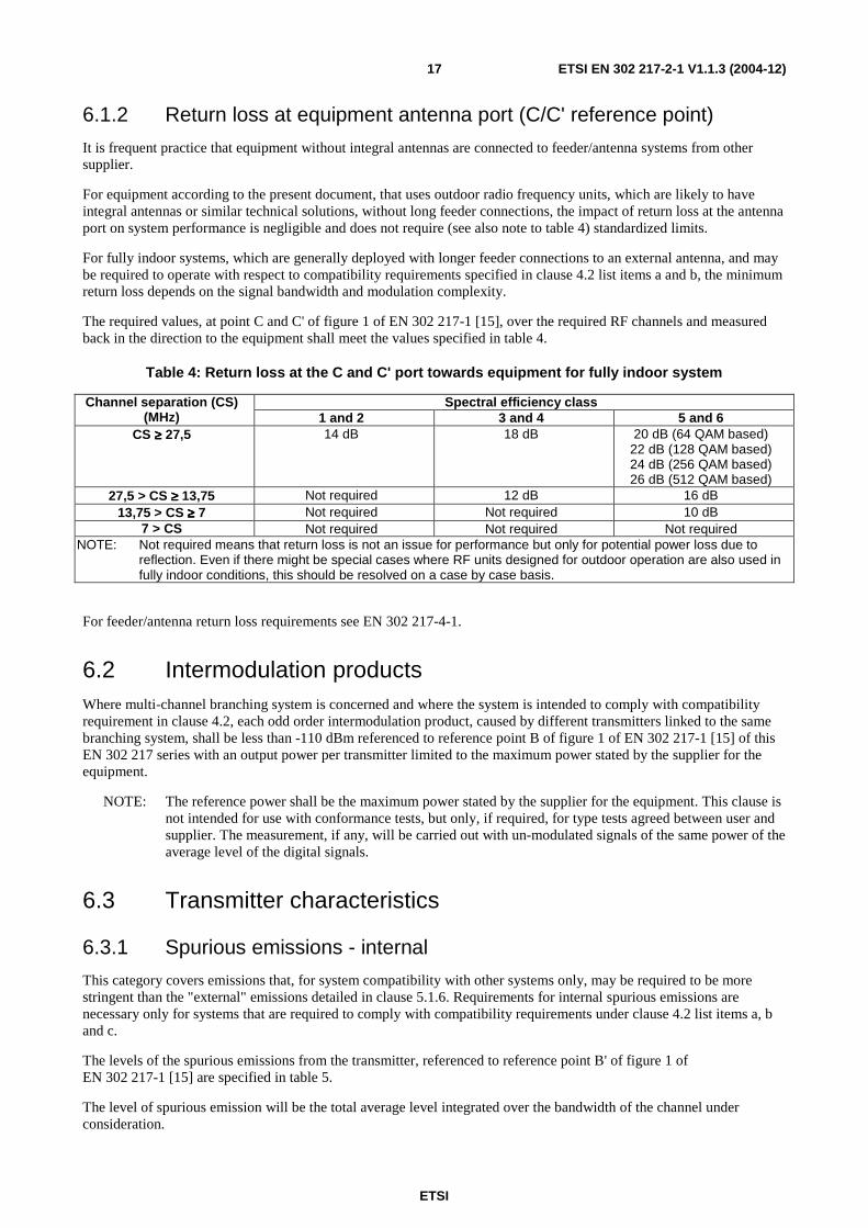
6.1.2 Return loss at equipment antenna port (C/C' reference point)
It is frequent practice that equipment without integral antennas are connected to feeder/antenna systems from other supplier.
For equipment according to the present document, that uses outdoor radio frequency units, which are likely to have integral antennas or similar technical solutions, without long feeder connections, the impact of return loss at the antenna port on system performance is negligible and does not require (see also note to table 4) standardized limits.
For fully indoor systems, which are generally deployed with longer feeder connections to an external antenna, and may be required to operate with respect to compatibility requirements specified in clause 4.2 list items a and b, the minimum return loss depends on the signal bandwidth and modulation complexity.
The required values, at point C and C' of figure 1 of EN 302 217-1 [15], over the required RF channels and measured back in the direction to the equipment shall meet the values specified in table 4.
Table 4: Return loss at the C and C' port towards equipment for fully indoor system
Spectral efficiency class Channel separation (CS) (MHz) 1 and 2 3 and 4 5 and 6
CS ≥≥≥≥ 27,5 14 dB 18 dB 20 dB (64 QAM based) 22 dB (128 QAM based) 24 dB (256 QAM based) 26 dB (512 QAM based)
27,5 > CS ≥≥≥≥ 13,75 Not required 12 dB 16 dB 13,75 > CS ≥≥≥≥ 7 Not required Not required 10 dB
7 > CS Not required Not required Not required NOTE: Not required means that return loss is not an issue for performance but only for potential power loss due to
reflection. Even if there might be special cases where RF units designed for outdoor operation are also used in fully indoor conditions, this should be resolved on a case by case basis.
For feeder/antenna return loss requirements see EN 302 217-4-1.
6.2 Intermodulation products Where multi-channel branching system is concerned and where the system is intended to comply with compatibility requirement in clause 4.2, each odd order intermodulation product, caused by different transmitters linked to the same branching system, shall be less than -110 dBm referenced to reference point B of figure 1 of EN 302 217-1 [15] of this EN 302 217 series with an output power per transmitter limited to the maximum power stated by the supplier for the equipment.
NOTE: The reference power shall be the maximum power stated by the supplier for the equipment. This clause is not intended for use with conformance tests, but only, if required, for type tests agreed between user and supplier. The measurement, if any, will be carried out with un-modulated signals of the same power of the average level of the digital signals.
6.3 Transmitter characteristics
6.3.1 Spurious emissions - internal
This category covers emissions that, for system compatibility with other systems only, may be required to be more stringent than the "external" emissions detailed in clause 5.1.6. Requirements for internal spurious emissions are necessary only for systems that are required to comply with compatibility requirements under clause 4.2 list items a, b and c.
The levels of the spurious emissions from the transmitter, referenced to reference point B' of figure 1 of EN 302 217-1 [15] are specified in table 5.
The level of spurious emission will be the total average level integrated over the bandwidth of the channel under consideration.

ETSI
ETSI EN 302 217-2-1 V1.1.3 (2004-12) 18
Table 5: Internal levels for the transmitter spurious emissions
Controlling factor for requirement application Spurious emission frequency relative to
channel assigned frequency
Specification limit
Within transmit half band, digital interference to analogue systems on the same route, for digital systems with compatibility requirements as in clause 4.2 list item c.
Discrete (CW) spurious emissions within the same transmit half band
≤ -60 dBm
Within receive half band, digital into digital interference on the same local multi-channel branching/antenna system, for digital systems with compatibility requirements as specified in clause list item a.
All spurious signals within ≤ -90 dBm
Within receive half band, digital into digital interference for digital systems without branching network (i.e. single transceivers with duplexer), for digital systems with compatibility requirements as specified in clause 4.2 list item b.
The receive half band ≤ -70 dBm
6.4 Receiver characteristics
6.4.1 Input level range
The input Receiver Signal Level (RSL) range, under flat fading condition, where the BER is kept lower than a specified level (typically 10-6 for availability purpose and, for higher modulation formats, 10-10 for errored seconds performance) depends on various parameters such as, but not limited to, frequency band, hop length and spectrum efficiency class.
In principle, the highest is the range, the more flexible is the use of the equipment; however, high capacity systems with complex modulations (e.g. classes 5 and 6) suffer from one side of relatively higher RSL/BER thresholds and from the other side from more sensitivity to non-linear distortion caused by RX chain saturations. A unique standardized approach is not therefore advisable, nevertheless the necessary fade-margin shall be accommodated; the following "design objectives" are given for guidance only.
The lower limit for the RSL threshold for a Bit Error Ratio (BER) ≤ 10-6 is specified in the relevant annex of EN 302 217-2-2 [16]. The upper limit for the RSL, where the same BER of 10-6, due to non-linear distortions, is not exceeded is assumed to be XX dB above.
In the same fashion, the upper limit for the RSL where a lower BER of 10-y (typically 10-8 or 10-10) is not exceeded is assumed to be YY dB above the relevant RSL threshold for that BER also specified in the relevant annex of EN 302 217-2-2 [16].
Indicative values for XX dB and YY dB are given in table 6.

ETSI
ETSI EN 302 217-2-1 V1.1.3 (2004-12) 19
Table 6: Indicative design objectives for input level range
XX RSL range (dB) for : YY RSL range (dB) for : BER ≤ 10-6 BER ≤ 10-8 BER ≤ 10-10 Spectral efficiency class Spectral efficiency class Spectral efficiency class
Frequency Range
1 to 4 5 6 1 to 4 5 6 1 to 4 5 6
1,5 GHz to 3 GHz 47 − − − − − − − −
3 GHz to 11 GHz
50 (see
note 1)
47 (see
note 2)
See annex C − − − −
38/41 (see
note 7)
See annex C
13 GHz to 18 GHz 50
(see note 1)
47 (see
note 2) − 48
34 (see
note 5) − −
38/41 (see
notes 6 and 7)
−
23 GHz to 38 GHz
44 (see
note 3)
44 (see
note 3) −
41 (see
note 4)
41 (see
note 4) − − − −
40 GHz to 55 GHz
44 (see
note 3) − −
41 (see
note 4) − − − − −
NOTE 1: RSL higher than -20 dBm is not required. NOTE 2: RSL higher than -22 dBm is not required. NOTE 3: RSL higher than -23 dBm is not required. NOTE 4: RSL higher than -24 dBm is not required. NOTE 5: For channel spacing > 28 MHz only. NOTE 6: For channel spacing ≤ 28 MHz only. NOTE 7: Higher value for systems with compatibility requirements under clause 4.2. NOTE 8: In case of two-carriers systems (D.8 and E.4 systems referred in annex D and annex E,
respectively), when carrying STM-4 or when carrying 4 × STM-1, with each STM-1 mixed on both carriers, the test shall be made changing the RSL of both carrier simultaneously. For more details see annex G (clause G.3) in EN 302 217-2-2 [16].
These limits apply without interference and are referenced to point B (points B and C may coincide when simple duplexer is used) of figure 1 of EN 302 217-1 [15].
For equipment designed to operate only with ATPC as a fixed permanent feature the above maximum input levels are reduced by an amount up to the ATPC range.
6.4.2 Spurious emissions - internal
For systems without the compatibility requirements of clause 4.2 there is no requirement.
When equipment is required to share the same antenna with other equipment, the spurious emissions limits, referenced to point B, are specified below in table 7.
The required level will be the total average level integrated over the bandwidth of the channel under consideration.
Table 7: Limits of spurious emissions-internal
Controlling factor Specification limit Spurious falling in the same receive half-band for systems with compatibility requirements of clause 4.2 list item a.
≤ -110 dBm
Spurious falling in the same receive half-band for systems with compatibility requirements of clause 4.2 list item b.
≤ -70 dBm
NOTE: In addition, when compatibility with FDM systems on the same branching/antenna system is required, more stringent limits for CW lines (e.g. L.O. residual emission) might be necessary, ranging from ≤ -85 dBm to ≤ -125 dBm, according to the actual interfered baseband frequency of the analogue system and the possible additional decoupling due to local IPI of the antenna (conventionally assumed to be 40 dB).
ETSI
ETSI EN 302 217-2-1 V1.1.3 (2004-12) 20
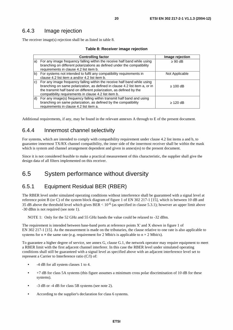
6.4.3 Image rejection
The receiver image(s) rejection shall be as listed in table 8.
Table 8: Receiver image rejection
Controlling factor Image rejection a) For any image frequency falling within the receive half band while using
branching on different polarizations as defined under the compatibility requirements in clause 4.2 list item b.
≥ 90 dB
b) For systems not intended to fulfil any compatibility requirements in clause 4.2 list item a and/or 4.2 list item b.
Not Applicable
c) For any image frequency falling within the receive half band while using branching on same polarization, as defined in clause 4.2 list item a, or in the transmit half band on different polarization, as defined by the compatibility requirements in clause 4.2 list item b.
≥ 100 dB
d) For any image(s) frequency falling within transmit half band and using branching on same polarization, as defined by the compatibility requirements in clause 4.2 list item a.
≥ 120 dB
Additional requirements, if any, may be found in the relevant annexes A through to E of the present document.
6.4.4 Innermost channel selectivity
For systems, which are intended to comply with compatibility requirement under clause 4.2 list items a and b, to guarantee innermost TX/RX channel compatibility, the inner side of the innermost receiver shall be within the mask which is system and channel arrangement dependent and given in annex(es) to the present document.
Since it is not considered feasible to make a practical measurement of this characteristic, the supplier shall give the design data of all filters implemented on this receiver.
6.5 System performance without diversity
6.5.1 Equipment Residual BER (RBER)
The RBER level under simulated operating conditions without interference shall be guaranteed with a signal level at reference point B (or C) of the system block diagram of figure 1 of EN 302 217-1 [15], which is between 10 dB and 35 dB above the threshold level which gives BER ≤ 10-6 (as specified in clause 5.3.1); however an upper limit above -30 dBm is not required (see note 1).
NOTE 1: Only for the 52 GHz and 55 GHz bands the value could be relaxed to -32 dBm.
The requirement is intended between base-band ports at reference points X' and X shown in figure 1 of EN 302 217-1 [15]. As the measurement is made on the tributaries, the clause relative to one rate is also applicable to systems for n × the same rate (e.g. requirement for 2 Mbit/s is applicable to n × 2 Mbit/s).
To guarantee a higher degree of service, see annex G, clause G.1, the network operator may require equipment to meet a RBER limit with the first adjacent channel interferer. In this case the RBER level under simulated operating conditions shall still be guaranteed with a signal level as specified above with an adjacent interference level set to represent a Carrier to Interference ratio (C/I) of:
• -4 dB for all system classes 1 to 4.
• +7 dB for class 5A systems (this figure assumes a minimum cross polar discrimination of 10 dB for these systems).
• -3 dB or -4 dB for class 5B systems (see note 2).
• According to the supplier's declaration for class 6 systems.

ETSI
ETSI EN 302 217-2-1 V1.1.3 (2004-12) 21
NOTE 2: Class 5B systems are basically sensitive to interference (e.g. 128 states with a roll off of approximately 20 %); they are standardized for network applications that include adjacent channels on a parallel route, sometimes with terminal co-located stations shared by different network operators. In such cases, even if nominal power (or EIRP) is kept equal through common spectrum management practice, the power tolerance may endanger proper error performance with particular regard to Errored Seconds (ES) objectives unless a tighter specification for adjacent channel sensitivity is offered. Therefore it is required that either the transmitter output power tolerance is reduced or the adjacent channel sensitivity is enhanced as shown in table 9.
Table 9 (to note 2): C/I vs. output power tolerance for RBER of class 5B systems
Output power tolerance 1st adjacent channel C/I Option 1 +2 dB / −1 dB −3 dB (see note) Option 2 ±2 dB −4 dB (see note)
NOTE: Measurement of RBER under first adjacent interference conditions for 1 dB RSL degradation is thus:
for option 1 the level of interference shall be at 3 dB above the signal level (C/I = −3 dB); for option 2 the level of interference shall be at 4 dB above the signal level (C/I = −4 dB).
In the above conditions the RBER shall be:
• For systems capacity between 64 kbit/s and 192 kbit/s: RBER < 10-9.
• For systems capacity above 192 kbit/s and less than 34 Mbit/s: RBER < 10−10.
• For systems capacity equal 34 Mbit/s and less than 140 Mbit/s: RBER < 10−11.
• For system capacity equal to STM-0 in frequency bands at or below 18 GHz: RBER < 3 × 10⁻¹².
• For systems capacity at 140 Mbit/s and up to STM-4 Mbit/s (see note 3): RBER < 10−12.
NOTE 3: For STM-4 capacity on multi-channel trunk systems at or below 11 GHz (for long radio connections) a RBER < 10-13 may be required by the network.
This requirement is intended for the payload bit rates defined in clause 5 or equivalent payload rates as defined in annex F.
Systems designed for CCDP operation, shall guarantee RBER with its own cross-polar corresponding equipment active and set at a RSL difference, with respect to that under test, of less than 5 dB.
In case of two-carriers systems (D.8 and E.4 systems referred in annexes D and E, respectively), when carrying STM-4 or when carrying 4 × STM-1, with each STM-1 mixed on both carriers, the test shall be made changing the RSL of both carrier simultaneously. For more details see annex G (clause G.3) in EN 302 217-2-2 [16].
EN 301 126-1 [14] recognizes that this requirement is subject to a supplier declaration only. However, in clause G.1 some background information relating to the actual test methods and test confidence is given.
Annex G also provides the format for the minimum recording time and the maximum numbers of errors not to be exceeded.
6.5.2 Interference sensitivity for CCDP with XPIC operation
The level and impact of Cross Polar Co-channel Interference depends on the frequency band, class of equipment, climatic conditions, antenna discrimination and hop length. When these factors are favourable, CCDP can be achieved without the use of an XPIC.
Whenever XPIC is implemented for class 5 and 6 systems, with channel separations from 27,5 MHz to 56 MHz, and for class 6 systems, with channel separations of 40 MHz, the following applies; the "internal interference" is hereby considered to be that given by the twin systems sharing the same XPIC system.

ETSI
ETSI EN 302 217-2-1 V1.1.3 (2004-12) 22
6.5.2.1 Co-channel "internal" interference sensitivity in flat fading conditions
For the frequency bands given under clause 4.1 the limits of the co-channel interference sensitivity for the system are given in table 10.
Table 10: Degradation versus C/I (co-channel "internal" interference)
Reference BER 10-6 10-6 RSL Degradation 1 dB 3 dB
C/I (dB) for class 5 equipment 17 13 C/I (dB) for class 6 equipment 24 20
Referring to the measurement test bench in annex G, note that measurements must be made adding the same values of noise and interference to both the paths, and varying the phase shifter of the interfering path in order to find the worst condition for this characteristic.
6.5.2.2 Co-channel "internal" interference sensitivity under dispersive fading conditions
This requirement is standardized for systems at 18 GHz and below.
To evaluate the performance during multipath propagation, dispersive cross-polarized main signals and non dispersive cross-polarization interferences are used in the test bench set up shown in clause G.2.
The system performance is evaluated by means of a signature degraded by an injected cross polar interference signal under the defined measurement conditions. The notch frequencies and notch depths are kept equal on both the wanted and simulated dispersed signal paths. The limits for BER = 10-6 are specified in table 11.
Table 11: Degraded signature versus C/I (co-channel "internal" interference)
Class / CS
C/I
Signature width
Signature depth
Class 5 / 28 MHz to 40 MHz
15 dB ±23 MHz 10 dB
Class 5 / 55 MHz or 56 MHz
15 dB ±36 MHz 5 dB
Class 6 / 40 MHz According to supplier declaration
According to supplier declaration
According to supplier declaration
6.5.3 Distortion sensitivity
If applicable, depending on the frequency band and/or the system baud-rate and distortion sensitivity:
• For a delay of 6,3 ns and a BER of 10-6 the width of the signature shall not exceed ±XX MHz relative to the channel assigned frequency and the depth shall not be less than YY dB.
• These limits are valid for both minimum and non-minimum phase cases and shall also be verified by the loss of synchronization and re-acquisition signatures (see IEC 60835-2-4 [21] and IEC 60835-2-8 [22]).
The values of the width and of the depth of the signature are system dependent and are given in the annex(es).
NOTE: It should be noted that, in some previous ENs for PP systems, signatures for BER = 10-3 where also standardized. However, according the present network requirements for high quality data transport, this BER is no longer representative for a unique performance and availability assessment. An intermediate limit for signatures, generally set between 10-6 and 10-3, may be appropriate for link performance prediction and may be defined by the supplier according to the kind of traffic and quality of service to be provided.

ETSI
ETSI EN 302 217-2-1 V1.1.3 (2004-12) 23
6.6 System characteristics with diversity Space, angle and frequency diversity techniques are applicable. In this clause, only combining techniques are considered.
6.6.1 Differential delay compensation
It shall be possible to compensate for differential absolute delays due to antennas, feeders and cable connections on the two diversity paths. The limit shall be at least 75 ns of differential absolute delay.
6.6.2 BER performance
When both receiver inputs (main and diversity, reference point B and BD) are fed with the same signal level with an arbitrary phase difference, the input level limits for the specified BER values defined under clause 5.3.1, shall be lower than those given under clause 5.3 for the case without diversity:
• More than 2,5 dB for IF or baseband combining systems.
• More than 1,5 dB for RF combining systems.
• No improvement for baseband switch systems.

ETSI
ETSI EN 302 217-2-1 V1.1.3 (2004-12) 24
Annex A (normative): Frequency bands from 1,4 GHz to 2,7 GHz
A.0 Introduction The following fixed point-to-point digital relay systems are covered in this annex (see note):
• A.1: Low capacity point-to-point digital radio systems operating in the 1,4 GHz frequency band.
• A.2: Low and medium capacity point-to-point digital radio systems operating in the frequency range 2,1 GHz to 2,6 GHz.
NOTE: These systems were previously specified in EN 300 630 (system A1) and in EN 300 633 (system A2) (see both references in the bibliography). In some cases, equipment were specified in these ENs with a different number for efficiency class that has been renumbered here, for coherence with all P-P systems in this EN 302 217 series (e.g. class 4 was specified as class 3). However, this does not change the actual spectral efficiency and would not impact upon the frequency planning. Reference to those ENs can be found in the bibliography.
Besides those characteristics set out in the main body of the present document or in EN 302 217-2-2 [16], table A.1 summarizes requirements that are specific for the above systems.
Table A.1: Additional specific requirements for family A systems
Characteristics and requirements System A1 System A2 Special compatibility requirements between systems (clause 4.2)
No special compatibility under bullets a) through c) of clause 4.2 is required
Transmitter power tolerance B = +2 dB/-1 dB Radio frequency tolerance
No specific value is requested, however, Radio frequency tolerances shall be included in the spectrum masks
Receiver image rejection
The definition of a receiver image rejection is not applicable to receivers with direct demodulation Due to particular conditions of frequency allocations in bands below 3 GHz, independently from requirements due to special compatibility situations set in clause 6.4.3, the receiver image(s) rejection shall be: - Class 1 and 2 75 dB minimum; - Class 3: 85 dB minimum.

ETSI
ETSI EN 302 217-2-1 V1.1.3 (2004-12) 25
Annex B (normative): Frequency bands from 3 GHz to 11 GHz (channel separation up to 30 MHz)
B.0 Introduction The following fixed point-to-point digital relay systems are covered in this annex (see note):
• B.1 Low and medium capacity and STM-0 digital radio system.
• B.2 High capacity digital radio systems carrying 1 × STM-1 signals and operating in frequency bands with about 30 MHz channel spacing and alternated arrangements (ACAP).
• B.3 High capacity digital radio systems carrying SDH signals (up to 2 × STM-1) in frequency bands with about 30 MHz channel spacing and using Co-polar arrangements (ACCP) or Co-Channel Dual Polarized (CCDP) operation.
NOTE: These systems were previously specified in EN 300 234 (system B.2), EN 301 127 (system B.3), EN 301 216 (system B.1) (see them in the bibliography). Among B.1 systems a 2 × STM-0 class 5B system, not included in EN 301 216 has been introduced. In some cases, equipment were specified in these ENs with a different number for efficiency class that has been renumbered here, for coherence with all P-P systems in this EN 302 217 series (e.g. classes 2, 4, and 5(A and B) where specified in EN 301 216 as 1, 2 and 3). However, this does not change the actual spectral efficiency and would not impact upon the frequency planning. Reference to those ENs can be found in the bibliography.
Besides those characteristics set out in the main body of the present document or in EN 302 217-2-2 [16] of this EN 302 217 series, table B.1 summarizes requirements that are specific for the above systems.
Table B.1: Additional specific requirements for family B systems
Characteristics and requirements
System B.2 System B.3 System B.1
Special compatibility requirements between systems (clause 4.2)
All list items a through to c of clause 4.2 may
be applicable
List items a through to c of clause 4.2 may be
applicable
List items b of clause 4.2 may be
applicable Transmitter output power tolerance (clause 5.1.3)
± A = ±1 dB ± B = ±2 dB
Transmitter Radio Frequency (RF) spectrum mask
(clause 5.1.4)
Clause B.2.1 Clause B.3.1 None
Transmitter radio frequency tolerance
(clause 5.1.7)
±Y = ±30 ppm ±X = ±50 ppm or ±XX = ±400 kHz (whichever is
more stringent)
±XX = ±15 ppm for equipment operating with channel spacing lower than 14 MHz;
and, ±XX = ±30 ppm for
equipment operating with channel spacing
greater than or equal to 14 MHz.
Receiver Innermost channel selectivity (clause 6.4.4)
Clause B.2.2 Clause B.3.2 None
Distortion sensitivity (clause 6.5.3)
±XX = ±20 MHz YY = 11 dB
±XX = ±19 MHz YY = 13 dB
and clause B.3.3 for dynamic behaviour
Clause B.1.1

ETSI
ETSI EN 302 217-2-1 V1.1.3 (2004-12) 26
B.1 System B.1 (2 - 2 × 34 Mbit/s; STM-0 - 2 × STM-0/ 3 GHz - 11 GHz/1,75 MHz - 29,65 MHz)
B.1.1 Distortion sensitivity The parameters for distortion sensitivity signatures are given in table B.2 only for medium capacity systems (i.e. 34 Mbit/s, 2 × 34 Mbit/s STM-0 and 2 × STM-0).
For a delay of 6,3 ns and BER of 10-6 the signature width (±XX) and depth (YY) should not exceed the values in table B.2.
Table B.2: Signature width and depth
Signature for BER = 10-6 Spectrum efficiency class
Nominal bit rate (Mbit/s)
Channel spacing (MHz) Width (MHz) Depth (dB)
Class 2 34 28/29/29,65/30 ±17 11 Class 3 STM-0 28/29/29,65/30 ±13 14
34 14/14,5/15 ±11 14 2 × 34 28/29/29,65/30 ±20 14 STM-0 20 to 2 × 11,662 ±13 14 STM-0 14/14,5/15 ±11 15
Class 4
2 × STM-0 28/29/30 ±22 15 Class 5B 2 × 34 14/14,5/15 (ACCP) ±9 17
NOTE: All signature widths are relative to the assigned channel centre frequency.
B.2 System B.2 (STM-1 / 3 GHz - 8 GHz/about 30 MHz ACAP)
B.2.1 Radio Frequency (RF) spectrum mask Clause 4.2 provides compatibility requirements. The compatibility requirements provide options for single-channel and multi-channel RF branching systems. When considering the compatibility requirements in clause 4.2 list item a and/or list item b, the RF spectrum mask shall take into consideration the effects of system interoperability when selecting normal channels or the innermost channel (see below).
Limits of masks in figures B.1 to B.3 are for normal and innermost channels of systems which are intended to comply with compatibility requirement under clause 4.2 list item a and/or list item b. The limits marked (a) in figures B.1 to B.3 shall be verified directly by measurement. Since it is not possible to measure attenuation values up to 105 dB directly, values of the relative power spectral density below -65 dB in figures B.1 to B.3 (curve b) should be subject to a supplier declaration.
NOTE: These values may be evaluated by adding a measured filter characteristic to the spectrum measured at reference point A' of figures B.1 to B.3. Due to the limitations of some spectrum analysers, difficulties may be experienced when testing high capacity/wideband systems. In this event, the following options are to be considered: measurement using high performance spectrum analyser, use of notch filters and the two step measurement technique. Where difficulties are experienced, the plots of one test conducted at ambient and environmental extremes may be produced as evidence to conformance to the spectrum mask.
Figure B.1 shows limits for any channel.
For the lower 6 GHz (L6) band, where the centre gap (44,49 MHz) is particularly small, for guaranteeing compatibility between the innermost channels, a mask is specified for the innermost edges of the centre gap channels 8 and 1', the mask is given in figure B.2.

ETSI
ETSI EN 302 217-2-1 V1.1.3 (2004-12) 27
For the 7 GHz band, when the centre gap is 56 MHz, for guaranteeing compatibility between co-polarized signals innermost channels, a mask is specified for the innermost edges of the centre gap channels, the mask is given in figure B.3.
K10
-35
-65
-105
0 f1 f2f3 f4
(b)
(a)
f5
Relativepower
spectraldensity
[dB]
K1 (dB)
f 1 (MHz)
f 2 (MHz)
f 3 (MHz)
f 4 (MHz)
f 5 (MHz)
+1 13 20 21 31,5 60
Figure B.1: Limits of power spectral density for normal channels (class 5A) (reference point B')

ETSI
ETSI EN 302 217-2-1 V1.1.3 (2004-12) 28
K10
-35
-65
-85
-105
0
-95
f1 f2f3 f4 f5 f6 f7
(a)
(b)
Relativepower
spectraldensity
[dB]
K1 (dB)
F 1 (MHz)
f 2 (MHz)
f 3 (MHz)
f 4 (MHz)
f 5 (MHz)
F 6 (MHz)
f 7 (MHz)
+1 13 20 21 28,5 32 40 60
Figure B.2: Limits of power spectral density for the innermost channels (class 5A), L6 GHz band (reference point B')
K10
-35
-65
-105
0 f1 f2f3 f4 f5
(a)
(b)
Relativepower
spectraldensity
[dB]
K1 (dB)
f 1 (MHz)
f 2 (MHz)
f 3 (MHz)
f 4 (MHz)
f 5 (MHz)
+1 13 20 21 29.5 42
Figure B.3: Limits of power spectral density for the inner edges of innermost channels (class 5A) in the 7 GHz band with 56 MHz co-polar centre gap (reference point B')

ETSI
ETSI EN 302 217-2-1 V1.1.3 (2004-12) 29
B.2.2 Receiver innermost channel selectivity For systems which are intended to comply with compatibility requirements under clause 4.2 list item a and/or list item b, to guarantee innermost TX/RX channel compatibility in L6 GHz band, the inner side of the innermost receiver shall be within the mask given in figure B.4.
(dB)
-4
1
-47
-105
0 13 15 22 24 36 (MHz)
Frequency from the nominal centre frequency.
Figure B.4: Overall minimum receiver selectivity of the inner side of innermost receiver for L6 GHz band (class 5A)
Since it is not considered feasible to make a practical measurement of this characteristic, the supplier shall give the design data of the filters implemented on this receiver.
B.3 System B.3 (2 × STM-1 / 3 GHz -8 GHz / about 30 MHz CCDP)
B.3.1 Radio Frequency (RF) spectrum mask Spectrum masks in figures B.5 and B.6 (see note 1) are applicable to multiple channel systems (typically in fully indoor trunk applications) where all channels in both polarization are exploited under the same branching/antenna system and systems from different suppliers may be required to operate under the same branching system according to clause 4.2 list item a (see note 2).
As far as innermost channels are concerned, the masks are relevant only to cross-polar connected channels, typical for operation with two transmitting antennas. For single antenna operation, the required decoupling of the even and odd channels, the (possible) summing hybrid, circulators and relevant spectrum masks are under study.
NOTE 1: Due to the more stringent requirements than that of systems operating with adjacent cross-polarized channels, the given masks are absolute maximum limits. Actual systems shall provide a Net Filter Discrimination (NFD) of adequate value to fulfil the adjacent channel interference limits set out in clause 5.3.2.2. These values may be derived from direct computation or measurement of the actual emitted spectrum and receiver RF, IF and BB selectivity.

ETSI
ETSI EN 302 217-2-1 V1.1.3 (2004-12) 30
NOTE 2: Less stringent compatibility, according to 4.2 b), may be applicable when frequency reuse is not implemented (i.e. the second polarization, in ACAP operation, is still used by or reserved for equipment from another supplier). Even if used on different antenna systems, channels of B.3 systems, adjacent to B.2 systems, shall be used, on the same route, cross-polarized and without frequency reuse.
0
Frequency offset from nominal centre frequency [MHz]
-11
0
+2/12
-6/14.5
-32/17 -32/18
-45/22
-65/34 (a)
-85/32
-95/40
-105/60
( dB / MHz )
(b)
(c)
10 20 30 40 50 60 F 1
-10
0
-
90
-80
-
70
-60
-
50
-40
-
30
-20
-
10
0
Po
wer
sp
ectr
al d
ensi
ty r
ela
tive
to c
entr
e fr
equ
ency
[dB
]
F1 = 72,5 MHz (for channel separation 29 MHz); 74,125 MHz (for channel separation 29,65 MHz); 75 MHz (for channel separation 30 MHz).
NOTE: (a) limit for direct measurement
(b) normal channels (c) inner edges of innermost channels for L6 GHz band
Figure B.5: Spectrum mask for frequency bands with 29 MHz , 29,65 MHz
and 30 MHz channel (reference point B')

ETSI
ETSI EN 302 217-2-1 V1.1.3 (2004-12) 31
0
Frequency offset from nominal centre frequency [MHz]
-11
0
+2/12
-10/14.5
-32/16 -32/17
-45/20
-65/28 (a)
-105/60
(dB/MHz)
(b)
10 20 30 40 50 60 70
-10
0 -
90 -
80 -
70 -
60 -
50 -
40 -
30 -
20 -
10 0
Po
wer
sp
ectr
al d
ensi
ty r
elat
ive
to c
entr
e fr
equ
ency
[d
B]
NOTE: (a) limit for direct measurement (b) normal channels (valid also for the innermost channels with 56 MHz centre gap)
Figure B.6: Spectrum mask for frequency bands
with 28 MHz channel separation (reference point B'):
B.3.2 Innermost channel selectivity For systems which are intended to comply with compatibility requirements under clause 4.2 list item a and/or list item b, in order to guarantee innermost TX/RX channel compatibility, the inner side of the innermost receiver shall be within the limits of the mask shown in figure B.7.

ETSI
ETSI EN 302 217-2-1 V1.1.3 (2004-12) 32
Figure B.7 shows a mask for the overall relative receiver sensitivity for the inner edges of the innermost channels of the L6 GHz band and for frequency bands with 28 MHz channel spacing and a 56 MHz centre gap. The receiver selectivity may be evaluated by calculating the effect of the receiver filter response on the received signal.
In figure B.7 the mask (a) is for systems that offers compatibility requirements according to clause 4.2 list item a, where different supplier equipment may share the same branching system; the mask (b) is for systems that do not offer compatibility requirements according to clause 4.2 list item a, but different supplier equipment may still share the same site on different antennas.
0
Frequency offset from actual centre frequency[MHz]
Rec
eive
r Se
lect
ivity
[dB
]
-11
0
+1/11.5
-6/14.5
-32/17
-45/20
-105/36
(dB/ MHz )
-45/22
10 20 30 40 50 60 70
-10
0 -
90 -
80 -
70 -
60 -
50 -
40 -
30 -
20 -
10 0
-70/28
(a)
(b)
NOTE: (a) Systems sharing the same branching) (b) Systems sharing the same site on different antennas
Figure B.7: Limits for the receiver selectivity for the inner edges of the
innermost channels in the 6L GHz band (reference point B')

ETSI
ETSI EN 302 217-2-1 V1.1.3 (2004-12) 33
B.3.3 Distortion sensitivity In addition to static signature requirement, the sensitivity to dynamic fading is verified with the following parameters:
• For a notch speed up to 100 MHz/s and a BER = 10-6 the notch depth shall not fall below a value of 12 dB (sweeping in ± half channel spacing).

ETSI
ETSI EN 302 217-2-1 V1.1.3 (2004-12) 34
Annex C (normative): Frequency bands from 3 GHz to 11 GHz (channel separation 40 MHz)
C.0 Introduction The following fixed point-to-point digital relay systems are covered in this annex (see note):
• C.1 High capacity fixed radio systems carrying SDH signals (up to 2 × STM-1) in frequency bands with 40 MHz channel spacing and using Co-Polar arrangements (ACCP) or Co-channel Dual Polarized (CCDP) operation.
• C.2 High capacity digital radio systems carrying STM-4 in two 40 MHz channels or 2 × STM-1 in a 40 MHz channel with alternate (ACAP) channel arrangement.
• C.3 High capacity digital radio systems transmitting STM-4 or 4 × STM-1 in a 40 MHz radio frequency channel using Co-Channel Dual Polarized (CCDP) operation.
NOTE: These systems were previously specified in EN 301 277 (system C.3), EN 301 461 (system C.1), EN 301 669 (system C.2) (see them in the bibliography). In some cases, equipment were specified in these ENs (e.g.) with a different or no number for efficiency class that has been renumbered here, for coherence with all P-P systems in this EN 302 217 series (e.g. class 6(A and B) was not specified in EN 301 669 and EN 301 277). However, this does not change the actual spectral efficiency and would not impact upon the frequency planning. Reference to those ENs can be found in the bibliography.
Besides characteristic set out in the main body of the present document or in EN 302 217-2-2 [16], table C.1 summarizes requirements that are specific to the above systems.
Table C.1: Additional specific requirements for family C systems
Characteristics and requirements
System C.1 System C.2 System C.3
Special compatibility requirements between
systems
Item list a of clause 4.2 may be applicable
Items b through c of clause 4.2 may be
applicable
Items b and c of clause 4.2 may be
applicable Transmitter output power tolerance (clause 6.4.3)
± A = ±1 dB ± B = ±2 dB
B = ±1 dB B = ±1 dB
Transmitter Radio Frequency (RF) spectrum
mask
Clause C.1.1 Clause C.2.1 Clause C.3.1
Transmitter radio frequency tolerance
±Y = ±30 ppm ±X = ±50 ppm or ± XX = ±400 kHz
(whichever is more stringent)
±XX = ±30 ppm ±XX = ±20 ppm
Receiver input level range Clause 6.4.1 Clause C.2.2 Clause C.3.2 Distortion sensitivity Clause C.1.2 ±XX = ±22 MHz
YY = 16 dB ±XX = ±27 MHz
YY = 14 dB and clause C.3.3 for
dynamic behaviour and measurement
conditions in both static and dynamic cases

ETSI
ETSI EN 302 217-2-1 V1.1.3 (2004-12) 35
C.1 System C.1 (2 × STM-1 / 3-11 GHz / 40 MHz - CCDP)
System C.1 includes two different sets of parameters, both intended for ACCP or CCDP operation (class 5B) but with sensible difference in some requirements. They are here formally identified as type 1 and 2:
• Type 1 is based on 30 MHz-like system technology (i.e. based on 128 states modulation).
• Type 2 is based on 40 MHz-like system technology (i.e. based on 64 states modulation).
C.1.1 Radio Frequency (RF) spectrum mask Spectrum mask in figure C.1 are applicable to multiple-channel systems (systems typically in fully indoor trunk applications) where all channels in both polarization are exploited under the same branching/antenna system and systems from different suppliers may be required to operate under the same branching system according to clause 4.2 list item a.
-110
-100
-90
-80
-70
-60
-50
-40
-30
-20
-10
0
10
0 20 40 60 80 100
Frequency offset from actual centre frequency [MHz]
Rel
ativ
e P
ow
er S
pec
tral
Den
sity
[d
B]
a) Normal channels b) Inner edges 5, U6 GHzc) Direct mesurement limit
1 dB / 14 MHz
-35 dB / 24 MHz
-65 dB / 39.5 MHz
-95 dB / 55 MHz
a)
b)
-95 dB / 75 MHz
-65 dB / 59.5 MHz
-10 dB / 19.5 MHz
c)
Figure C.1: Limits of power spectral density (reference point B')

ETSI
ETSI EN 302 217-2-1 V1.1.3 (2004-12) 36
C.1.2 Distortion sensitivity For the different equipment types the requirements in table C.2 apply.
Table C.2: Signature width and depth
Signature for BER = 10-6 Spectrum efficiency class
Nominal bit rate (Mbit/s)
Channel spacing (MHz) Width (±±±±XX) Depth (YY)
Class 5B type 1 STM-1 40 ±19 MHz 12 dB Class 5B type 2 STM-1 40 ±19 MHz 16 dB
NOTE: All signature widths are relative to the assigned channel centre frequency.
The sensitivity to dynamic fading is not the subject of standardization, however it may be evaluated with the following parameters:
• For a notch speed up to 100 MHz/s (sweeping activated in ± half channel spacing), with a notch depth 1 dB less stringent than the above figures for BER = 10-6, the BER should not be higher than 10-6.
C.2 System C.2 (2 × STM-1 / 3 GHz -11 GHz / 40 MHz - ACCP)
C.2.1 Radio Frequency (RF) spectrum mask Clause 4.2 provides compatibility requirements. The compatibility requirements provide options for single-channel and multi-channel RF branching systems. When considering the compatibility requirements in clause 4.2 list item b, the RF spectrum mask shall take into consideration the effects of system interoperability when selecting normal channels or the innermost channel (see below).
The spectrum mask given in figure C.2, is applicable to all frequency bands, it guarantees suitable performance for systems operating on the same route and innermost channel operation.
Relative power spectral density [dB]
1
-32
-65-65/45
-32/27
1/19.5
-90
-90/44
-50/35
-32/25
-100
-90
-80
-70
-60
-50
-40
-30
-20
-10
0
10
0 20 40 60 80 100
Frequency offset from the actual centre frequency [MHz]
normal channels innermost channels 5, U6
dB/MHz
Figure C.2: Limits of spectral power density (reference point B')

ETSI
ETSI EN 302 217-2-1 V1.1.3 (2004-12) 37
C.2.2 Receiver input level range The lower limit for the receiver input level is defined by the threshold level for Bit Error Ratio (BER) = 10-6. The upper limit for the receiver input level, where a BER of 10-10 may only be exceeded shall be for levels greater than -27 dBm.
These limits apply without interference and are referenced to point B.
C.3 System C.3 (4 × STM-1/3 GHz -11 GHz/40 MHz - CCDP)
C.3.1 Transmitter Radio Frequency (RF) spectrum mask Clause 4.2 provides compatibility requirements. The compatibility requirements provide options for single-channel and multi-channel RF branching systems. When considering the compatibility requirements in clause 4.2 list item a, the RF spectrum mask shall take into consideration the effects of system interoperability when selecting normal channels or the innermost channel (see below).
Limits of masks in figures C.3 and C.4 (for single and multi-carrier systems, respectively) are for normal and for the innermost side of the innermost channels of systems which are intended to comply with compatibility requirement under clause 4.2 List item a. The limits marked (a) in figures C.1 and C.2 shall be verified directly by measurement. Since it is not possible to measure attenuation values up to 110 dB directly, values of the relative power spectral density below -65 dB in figures C.3 and C.4 (curve b) should be subject to a supplier declaration.
NOTE: These values may be evaluated by adding a measured filter characteristic to the spectrum measured at reference point A' of figures C.3 and C.4. Due to limitations of some spectrum analysers, difficulties may be experienced when testing high capacity/wideband systems. In this event, the following options are to be considered: measurement using high performance spectrum analyser, use of notch filters and two step measurement technique. Where difficulties are experienced, the plots of one test conducted at ambient and environmental extremes may be produced as evidence to conformance to the spectrum mask.
22; -
40
19; +
1
92,5;
-110
75,5;
-65
35,5;
-65
0; +
1
-120
-110
-100
-90
-80
-70
-60
-50
-40
-30
-20
-10
0
10
20
0 20 40 60 80 100 120 140
Frequency offset from the actual centre frequency (MHz)
Rel
ativ
e p
ow
er s
pec
tral
den
sity
(d
B)
(a) Normal channels (b) Inner edges of 5 and U6 GHz
52,5; -110
Figure C.3: Limits for single carrier systems (reference point B')

ETSI
ETSI EN 302 217-2-1 V1.1.3 (2004-12) 38
0; +
1
22,5
; -50
28; -
50 37; -
65
77; -
65
100;
-105
19,7
5; +
1
20; -
20
-110
-100
-90
-80
-70
-60
-50
-40
-30
-20
-10
0
10
0 10 20 30 40 50 60 70 80 90 100
Frequency offset from the actual centre frequency (MHz)
Rel
ativ
e p
ow
er s
pec
tral
den
sity
(d
B)
(a) Normal channels (b) Inner edges of 5 and U6 GHz
60; -105
Figure C.4: Limits for multi-carrier systems (reference point B')
C.3.2 Receiver input level range The lower limit for the receiver input level shall be given by the threshold level for BER = 10-6. The upper limit for the receiver input level, where a BER of 10-10 may be exceeded shall be greater than -16 dBm. When ATPC is used the maximum input level for BER < 10-10 may be relaxed to -31 dBm.
These limits should apply without interference and are referenced to point B.
C.3.3 Distortion sensitivity Distortion shall be introduced in one polarization at a time and the error rate shall be measured for the total STM-4 or 4 × STM-1 signal.
In addition to static signature requirement, the sensitivity to dynamic fading is verified with the following parameters:
• Distortion shall be introduced in one polarization at a time and the error rate measured for the total STM-4 or 4 × STM-1 signal.
• A notch (6,3 ns delay) with a depth of 13 dB swept across the whole band (±20 MHz) with a speed not less than 150 MHz/s shall not cause a BER greater than 10-6.
• A notch (6,3 ns delay) swept down between 4 dB and 13 dB with a speed not less than 100 dB/s shall not cause a BER greater than 10-6. The measurement shall be performed for constant notch frequencies within the whole band (±20 MHz).

ETSI
ETSI EN 302 217-2-1 V1.1.3 (2004-12) 39
Annex D (normative): Frequency bands 13 GHz, 15 GHz and 18 GHz
D.0 Introduction The following fixed point-to-point digital relay systems are covered in this annex (see note):
• D.1 Low and medium capacity Plesiochronous Digital Hierarchy (PDH) radio systems operating in the 13 GHz, 15 GHz and 18 GHz frequency bands.
• D.2 Radio systems for the transmission of Sub-STM-0 digital signals operating in the 18 GHz frequency band.
• D.3 STM-0 digital radio systems operating in the 13 GHz, 15 GHz and 18 GHz frequency bands with about 28 MHz co-polar (ACCP) and 14 MHz cross-polar (ACAP) channel separation.
• D.4 STM-0 digital radio systems operating in the 13 GHz, 15 GHz and 18 GHz frequency bands with about 14 MHz co-polar (ACCP) channel separation.
• D.5 High capacity digital radio systems carrying 1 × STM-1 signals and operating in frequency bands with about 30 MHz channel separation and alternated arrangements (ACAP) operating in the 13 GHz and 15 GHz frequency bands.
• D.6 High capacity digital radio systems carrying SDH signals (up to 2 × STM-1) in frequency bands with about 30 MHz channel separation and using Adjacent Channel Co-polar (ACCP) arrangements or Co-Channel Dual Polarized (CCDP) operation operating in the 13 GHz and 15 GHz frequency bands.
• D.7 Radio systems for the transmission of STM-1 digital signals operating in the 18 GHz frequency band with channel separation of 55 MHz and 27,5 MHz.
• D.8 High capacity digital radio systems carrying STM-4, 4 × STM-1 or 2 × STM-1 signals in bands with 55 MHz or 56 MHz channel separation operating in the 15 GHz and 18 GHz frequency bands.
NOTE: These systems were previously specified in EN 300 430 (system D.7), EN 300 639 (system D.3), EN 300 786 (system D.4), EN 301 128 (system D.1), EN 301 787 (system D.2), EN 302 062 for 15 GHz and 18 GHz band only (system D.8), EN 300 234 for 13 GHz and 15 GHz bands only (system D.5) and EN 301 127 for 13 GHz and 15 GHz bands only (system D.6) (see them all in the bibliography). Among D.4 systems a 2 × STM-0 class 5B system, not included in EN 301 786 has been introduced. In some cases, equipment were specified in these ENs with a different number for efficiency class that has been renumbered here, for coherence with all P-P systems in this EN 302 217 series (e.g. classes 2, 4, and 5(A and B) where specified in EN 301 128 as 1, 2 and 3). However, this does not change the actual spectral efficiency and would not impact upon the frequency planning. Reference to those ENs can be found in the bibliography.
Besides characteristic set out in the main body of the present document or in EN 302 217-2-2 [16] of this EN 302 217 series, table D.1 summarizes requirements that are specific for the above systems.

ETSI
ETSI EN 302 217-2-1 V1.1.3 (2004-12) 40
Table D.1: Additional specific requirements for family D systems
Characteristics and
requirements
System D.7
System D.3
System D.4
System D.1
System D.2
System D.8
System D.5
System D.6
Special compatibility requirements
between systems
List items a and b of clause 4.2 may apply
Item b of clause 4.2 may apply
Item b of clause 4.2 may apply
Clause 4.2 list item b
may apply
Clause 4.2 list item b
may apply
None of the list items a
through c of clause 4.2 may
apply
List item a and b of
clause 4.2 may apply
List item a of clause 4.2 may
apply
Transmitter output power
tolerance
± B = ± 2 dB ±A = ±1 dB
Transmitter Radio Frequency
(RF) spectrum mask
Clause D.7.1 None None None None None Clause
B.2.1 Clause B.3.1
Transmitter radio frequency
tolerance (Note)
±X = ±15 ppm
±X = ±30 ppm
±X = ±15 ppm
±X = ±10 ppm
±X = ±10 ppm
±X = ±15 ppm
±Y = ±30 ppm ±X = ±50 ppm or ±XX = ±400 kHz
(whichever is the more stringent)
Distortion sensitivity
Clause D.7.2
±XX = ±13 MHz
YY = 20 dB (see
note 2)
Clause D.4.1
Clause D.1.1
None ±XX =
±36 MHz YY =8 dB
±XX = ±20 MHz
YY = 11 dB
±XX = ±19 MHz
YY = 13 dB and clause B.3.3 for dynamic
behaviour NOTE 1: For class 5B equipment see also note 1 of clause 6.5.1. NOTE 2: Because rainfall in 18 GHz band is the main propagation factor limiting performance, in this band the above
limits are not mandatory.
D.1 System D.1 (2 / 2 × 34 Mbit/s / 13 GHz - 15 GHz - 18 GHz / 1,75 MHz / 28 MHz )
D.1.1 Distortion sensitivity For the frequency bands considered and for this system, rainfall may be considered as the main propagation factor limiting performance. Powerful equalizers to compensate propagation distortion are not considered for class 2 systems and frequency bands above the 13 GHz band, nor for class 3, 4 and 5 systems operating at bit rates lower than 34 Mbit/s.
No specific requirement is recommended, however, equipment with equalizers will be subject to a supplier's declaration of signature parameters for a two path propagation with a delay of 6,3 ns and a BER of 10-6.
D.2 System D.2 (sub STM-0 / 18 GHz / 3,5 MHz) See table D.1.
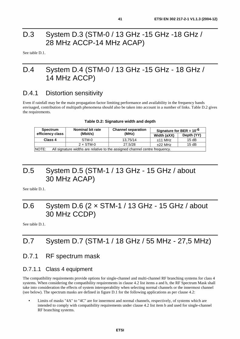
ETSI
ETSI EN 302 217-2-1 V1.1.3 (2004-12) 41
D.3 System D.3 (STM-0 / 13 GHz -15 GHz -18 GHz / 28 MHz ACCP-14 MHz ACAP)
See table D.1.
D.4 System D.4 (STM-0 / 13 GHz -15 GHz - 18 GHz / 14 MHz ACCP)
D.4.1 Distortion sensitivity Even if rainfall may be the main propagation factor limiting performance and availability in the frequency bands envisaged, contribution of multipath phenomena should also be taken into account in a number of links. Table D.2 gives the requirements.
Table D.2: Signature width and depth
Signature for BER = 10-6 Spectrum efficiency class
Nominal bit rate (Mbit/s)
Channel separation (MHz) Width (±±±±XX) Depth (YY)
Class 4 STM-0 13,75/14 ±11 MHz 15 dB 2 × STM-0 27,5/28 ±22 MHz 15 dB
NOTE: All signature widths are relative to the assigned channel centre frequency.
D.5 System D.5 (STM-1 / 13 GHz - 15 GHz / about 30 MHz ACAP)
See table D.1.
D.6 System D.6 (2 × STM-1 / 13 GHz - 15 GHz / about 30 MHz CCDP)
See table D.1.
D.7 System D.7 (STM-1 / 18 GHz / 55 MHz - 27,5 MHz)
D.7.1 RF spectrum mask
D.7.1.1 Class 4 equipment
The compatibility requirements provide options for single-channel and multi-channel RF branching systems for class 4 systems. When considering the compatibility requirements in clause 4.2 list items a and b, the RF Spectrum Mask shall take into consideration the effects of system interoperability when selecting normal channels or the innermost channel (see below). The spectrum masks are defined in figure D.1 for the following applications as per clause 4.2:
• Limits of masks "4A" to "4C" are for innermost and normal channels, respectively, of systems which are intended to comply with compatibility requirements under clause 4.2 list item b and used for single-channel RF branching systems.

ETSI
ETSI EN 302 217-2-1 V1.1.3 (2004-12) 42
• Limits of masks "4B" and "4D" are for innermost and normal channels, respectively, of systems which are intended to comply with compatibility requirements clause 4.2 list item a and used for multi-channel RF branching systems.
The masks "4A" to "4D", given in figure D.1, fix lower limits of 88 dB and 105 dB in order to control local interference between transmitters and receivers of different suppliers connected to the same antenna.
Since it is not possible to measure attenuation values up to 105 dB directly, values above 50 dB in figure D.1 should be subject to a supplier declaration.
NOTE: These values may be evaluated by adding a measured filter characteristic to the measured spectrum at reference point A' of figure 1 of EN 302 217-1 [15].
Mask 4A
-105 Mask 4B
f3 f2 f6 f5 fo
0
-30
+K1(dB)
Transmitter
Relative Spectral
Power Density
f1 f4
-88
f7
(dB)
-50
f8
Mask 4D
Mask 4C
NOTE: Frequency expressed from actual transmitter centre frequency (MHz). Mask 4A: Innermost channel, compatibility requirement clause 4.2 list item b. Mask 4B: Innermost channel, compatibility requirement clause 4.2 list item a. Mask 4C: Normal channel, compatibility requirement clause 4.2 list item b. Mask 4D: Normal channel, compatibility requirement clause 4.2 list item a. Figure D.1: Limits of spectral power density for class 4 systems (reference corner in table D.3)
(at reference point B')
Table D.3: Spectrum mask frequency limits for class 4 systems
Mask Ref.
Bit rate (Mbit/s)
Channel spacing (MHz)
K1 (dB)
f 1 (MHz)
f 2 (MHz)
f 3 (MHz)
f 4 (MHz)
f 5 (MHz)
f 6 (MHz)
f 7 (MHz)
f 8 (MHz)
4A 155 55 +1 22,5 33 70 n.a. 105 n.a. n.a. 180 4B 155 55 +1 22,5 33 70 n.a. n.a. 115 n.a. 180 4C 155 55 +1 22,5 33 70 85 n.a. n.a. 160 180 4D 155 55 +1 22,5 33 70 85 n.a. n.a. 160 180
D.7.1.2 Class 5B equipment
For D.7 systems class 5B, in EN 302 217-2-2 [16] , attenuation greater than 50 dB is not required for the spectrum mask floor relevant to R&TTE Directive [1] essential requirements; however, for guaranteeing RBER performance in the presence of multiple (i.e. 2nd, 3rd, etc.) adjacent channels regardless of the FEC algorithm implemented, a mask floor at 55 dB might be required (see note). The corresponding frequency corner may be derived extending the sixth segment of the mask (provided in annex D of EN 302 217-2-2 [16]) beyond point f6 down to intercept the -55 dB ordinate.
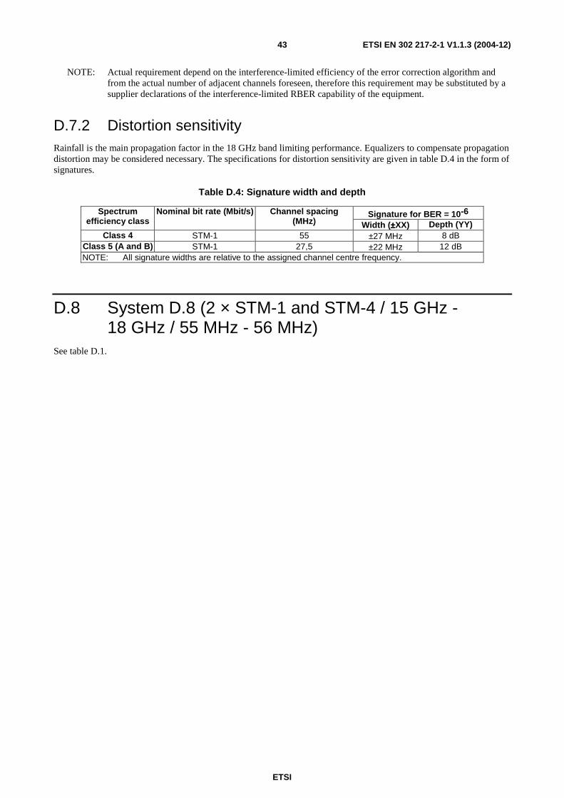
ETSI
ETSI EN 302 217-2-1 V1.1.3 (2004-12) 43
NOTE: Actual requirement depend on the interference-limited efficiency of the error correction algorithm and from the actual number of adjacent channels foreseen, therefore this requirement may be substituted by a supplier declarations of the interference-limited RBER capability of the equipment.
D.7.2 Distortion sensitivity Rainfall is the main propagation factor in the 18 GHz band limiting performance. Equalizers to compensate propagation distortion may be considered necessary. The specifications for distortion sensitivity are given in table D.4 in the form of signatures.
Table D.4: Signature width and depth
Signature for BER = 10-6 Spectrum efficiency class
Nominal bit rate (Mbit/s) Channel spacing (MHz) Width (±±±±XX) Depth (YY)
Class 4 STM-1 55 ±27 MHz 8 dB Class 5 (A and B) STM-1 27,5 ±22 MHz 12 dB NOTE: All signature widths are relative to the assigned channel centre frequency.
D.8 System D.8 (2 × STM-1 and STM-4 / 15 GHz - 18 GHz / 55 MHz - 56 MHz)
See table D.1.

ETSI
ETSI EN 302 217-2-1 V1.1.3 (2004-12) 44
Annex E (normative): Frequency bands from 23 GHz to 55 GHz
E.0 Introduction The following fixed point-to-point digital relay systems are covered in this annex (note):
• E.1 Radio systems for the transmission of digital signals operating in the 23 GHz frequency band;
• E.2 Radio system for the transmission of digital signals operating in the frequency range 24,5 GHz to 29,5 GHz.
• E.3 Radio systems for the transmission of digital signals operating in the 31 GHz, 32 GHz and 38 GHz frequency bands.
• E.4 High capacity digital radio relay systems carrying STM-4, 4 × STM-1 or 2 × STM-1 signals in bands with 55 MHz or 56 MHz channel separation operating in the frequency range 23 GHz to 38 GHz.
• E.5 Low and medium capacity digital radio systems operating in the 50 GHz frequency band.
• E.6 Radio systems for the transmission of digital signals operating in the 52 GHz frequency band.
• E.7 Radio systems for the transmission of digital signals operating in the 55 GHz frequency band.
NOTE: These systems were previously specified in EN 300 197 (system E.3), EN 300 198 (system E.1), EN 300 407 (system E.7), EN 300 431 (system E.2), EN 301 387 (system E.5), EN 301 786 (system E.6), EN 302 062 bands above 18 GHz only (system E.4) (see them all in the bibliography). Among E.1, E.2 and E.3 systems a 2 × STM-0 class 4 and 2 × 34 Mbit/s class 5B system, not included in previous relevant ENs have been introduced. In some cases, equipment were specified in these ENs with a different number for efficiency class that has been renumbered here, for coherence with all P-P systems in this EN 302 217 series. However, this does not change the actual spectral efficiency and would not impact upon the frequency planning.
Besides characteristic set out in the main body of the present document or in EN 302 217-2-2 [16], table E.1 summarizes requirements that are specific to the above systems. Reference to those ENs can be found in the bibliography.

ETSI
ETSI EN 302 217-2-1 V1.1.3 (2004-12) 45
Table E.1: Additional specific requirements for family E systems
Characteristics and requirements System E.3 System E.1 System E.7 System E.2 System E.5 System E.6 System E.4
Special compatibility requirements
between systems
None of the list items a
through to c of
clause 4.2 is applicable
List item b of
clause 4.2 may apply
None of the list items a
through to c of clause 4.2 is applicable
List item b of clause 4.2 may apply
None of the list items a
through to c of
clause 4.2 is applicable
None of the list items a
through to c of
clause 4.2 is applicable
None of the list items a
through to c of
clause 4.2 is applicable
Transmitter output power tolerance
(see note 1)
±A = ±2 dB ±B = ±3 dB
±B = ±2 dB ±B = ±3 dB ±B = ±2 dB ±A = ±2 dB ±B = ±3 dB
±B = ±3 dB
±A = ± 1 dB ±B = ±3 dB (31, 32 and
38 GHz bands)
±B = ±2 dB (23 to
28 GHz bands)
Transmitter Radio Frequency (RF) spectrum mask
Clause E.1 (see note 2)
Clause E.1 (see note 2) None Clause E.1
(see note 2) None None None
Radio frequency tolerance ±X = ±15 ppm ±X = ±20
ppm
±X = ±20 ppm
(class 1 equipment) ±X = ±10
ppm (class 2
equipment)
±X = ±15 ppm
Distortion sensitivity None ±XX
= ±36 MHz YY = 8 dB
NOTE 1: For class 5B equipment see also note 2 of clause 6.5.1. NOTE 2: For class 5B equipment only.
E.1 Systems E.1, E.2 and E.3: Transmitter spectrum mask for class 5B equipment
For E.1, E.2 and E.3 systems of class 5B, in EN 302 217-2-2 [16], attenuation greater than 50 dB is not required for the spectrum mask floor relevant to R&TTE Directive [1] essential requirements; however, for guaranteeing RBER performance in the presence of multiple (i.e. 2nd, 3
rd, etc.) adjacent channels regardless of the FEC algorithm
implemented, a mask floor at 55 dB might be required (see note). The corresponding frequency corner may be derived extending the sixth segment of the mask (provided in annex E of EN 302 217-2-2 [16] of this EN 302 217 series) beyond point f6 (for systems E1 and E2) or beyond point f5 (for system E3) down to intercept the -55 dB ordinate.
NOTE: Actual requirement depend on the interference-limited efficiency of the error correction algorithm and from the actual number of adjacent channels foreseen, therefore this requirement may be substituted by a supplier declarations of the interference-limited RBER capability of the equipment.

ETSI
ETSI EN 302 217-2-1 V1.1.3 (2004-12) 46
Annex F (normative): Transmission of packet data and combinations of other signals in bands from 3 GHz to 55 GHz
F.1 Introduction This annex provides the conditions under which the existing PDH/SDH specifications can be used for systems with traffic interface combinations other then those mentioned in the PDH/SDH specifications when mapped into proprietary transport modules (i.e. not mapped into conventional standardized PDH or SDH transport modules) (see note).
NOTE: This argument (limited to packet data interfaces only) was covered in a previous EN 301 785 (see bibliography).
F.2 General characteristics
F.2.1 Frequency characteristics and channel arrangements The equipment shall operate on frequency bands and channels arrangements in accordance with information provided in the relevant annex from A through to E (of the present document and of EN 302 217-2-2 [16]) selected from table F.1 of EN 302 217-2-2 [16].
F.2.2 Transmission capacities and equipment assessment For assessing such equipment against requirements set in this EN 302 217 series, it is necessary to select the set of equipment characteristics relevant to the channel spacing and the equipment classes of an equivalent PDH/SDH rate for the same frequency band from the referenced annexes A to E of the present document and EN 302 217-2-2 [16] of this EN 302 217 series. For maintaining a suitable spectral efficiency, the selection shall be made comparing the minimum required Radio Interface Capacities (RIC) with those conventional PDH/SDH rates as defined in table F.1 of EN 302 217-2-2 [16].
In the event that no PDH/SDH interface is available at base band level (reference points X, X' of figure 1 of EN 302 217-1 [15]), and no other means (even proprietary ones) are possible for a true bit-to-bit error count at reference point X, clause F.3.3 of EN 302 217-2-2 [16] describes how to translate the BER requirements from the PDH/SDH specification to verify compliance of the radio system when such a combination of interfaces includes at least an Ethernet interface.
Additional information on the derivation of BER/FER relationship and testing examples may be found in annex G, clause G.4, of the present document.
Clause G.1 provides requirements related to equipment Residual FER (RFER).
In the event that an Ethernet interface is not offered, but other standardized interfaces are used, the supplier shall declare an equivalent conversion table supported by technical evidence of its appropriateness.

ETSI
ETSI EN 302 217-2-1 V1.1.3 (2004-12) 47
Annex G (informative): Additional information
G.1 Residual Bit Error Ratio (RBER) and Frame Error Ratio (RFER)
In particular applications, where there is a high density of radio links in a specific area, e.g. nodal site, closely located radios may use adjacent channels. Therefore to guarantee the grade of service the equipment will need to meet RBER criteria in the presence of adjacent channel interference.
The RBER is standardized in order to match the ESR (or the BER) performance required by ITU-R transmission performance recommendations.
To have sufficient confidence in the measurement, where the BER is relatively low compared to the actual payload, the test time is very long. To have sufficient confidence in measuring RBER where it is relatively low compared to the actual payload bit rate, the testing period becomes significantly long. The actual background to this measurement and the BER figures are detailed in TR 101 036-1 (see bibliography).
When error correction feature is implemented it may be possible to reduce the measurement time by estimating the RBER, from the value tested without error correction, using the relevant BER improvement formula declared by the supplier.
The equipment maximum allowed number of errors level under simulated operating conditions is measured with a signal level at reference point B (or C) which is 10 dB above the RSL which gives BER ≤ 10-6 (as specified in clause 5.3.1 and in EN 302 217-2-2 [16]). All measurements will be made at the payload bit rate defined in clause 4.3.
Based on TR 101 036-1 (see bibliography) for a ≈50 % confidence results, the measurement period and maximum number of errors allowed are given in table G.1.
Table G.1: Maximum permitted number of bit errors
Bit rate (Network interface)
RBER objective Minimum recording time (hours)
Maximum allowed number of bit Errors
2 Mbit/s 10-10 16 12 8 Mbit/s 10-10 4 12
34 Mbit/s 10-11 10 12 STM-0 (systems above
18 GHz) 10-11 15 12
STM-0 (systems up to 18 GHz)
3 × 10-12 24 10
140 Mbit/s/STM-1 10-12 24 10 STM-4 10-12 6 10 STM-4 10-13 60 10
Another more practical, but with less confidence, option is to ensure that no errors occur during the minimum recording time shown in table G.1a for PDH and SDH signals and table G.1b for packet data signals; for other rates (possibly used under the provision of annex F) values may be extrapolated from the closest ones.

ETSI
ETSI EN 302 217-2-1 V1.1.3 (2004-12) 48
Table G.1a: PDH and SDH rates −−−− Zero errors recording times
Bit rate (Network interface) (Mbit/s)
RBER objective Minimum recording time (minutes)
Errors
2 10-10 82 0 8 10-10 21 0
34 10-11 50 0 STM-0
(systems above 18 GHz) 10-11 34 0
STM-0 (systems up to 18 GHz)
3 × 10-12 113 0
140/STM-1 10-12 108 0 STM-4 10-12 27 0 STM-4 10-13 270 0
Table G.1b: Packet data rates - Zero errors recording times
Bit rate under test (see note)
(Mbit/s)
RBER objective Minimum recording time (full loading) (see note)
(minutes)
Errors
10 10-10 17 0 100 10-11 17 0 100 3 × 10-12 57 0
1000 10-12 17 0 NOTE: In case the actual System Capacity (SC) does not allow Full Load Capacity (FLC) the
recording time will be increased by a factor FLC/SC (e.g. for a 10baseT load transported on a 8 Mbit/s system rate the recording time will become 17 × 10/8 ≈ 21 minutes).
G.2 Measurement test set for XPI characteristics In figure G.1, a measurement set-up is defined that allows simulating wanted signals affected by flat and/or dispersive fading conditions in the presence of XPI (Cross Polar Interference) where level and phase can be varied.
Noise
Noise
V - Pol Signal
Demodulator with XPIC
BER detector
Phase Shifter
H - Pol Signal
MOD
MOD
Pattern Generator
Fading Simulator
Pattern Generator
Fading Simulator
Figure G.1: IF measurement test set
As an alternative, a full RF test set-up may be used as shown in figure G.2.

ETSI
ETSI EN 302 217-2-1 V1.1.3 (2004-12) 49
XPIC (if any)
Pattern generator
Pattern generator
DEM BB
DEM BB
RX
RX
Phase Shifter
MOD TX
MOD TX
BB
BB
Error detector
Error detector
Figure G.2: RF measurement test set
G.3 Differential delay compensation range When frequency diversity function is integrated within the radio equipment it is desirable to provide the means to compensate for differential absolute delays due to antennas, feeders, cable connections, and relative velocities on different RF channels.
The range of adjustment of differential absolute delay in the order of about 600 ns with a minimum step size equivalent to the symbol period is considered adequate for most applications.
G.4 FER/BER equivalence and FER performance measurement equipment settings (example)
G.4.1 FER/BER equivalence FER and BER can be translated as described herein. Ethernet frames can range from 64 octets up to 1 522 octets. We use 64 octet frames for this proposal. An Ethernet frame is considered errored if at least one bit in the frame is errored. Assuming a normal distribution the probability of there being exactly one errored bit in a 64 octet frame is:
P = p× (1 - p) 64 × 8 - 1 × (64 × 8) where p = BER
The probability that a frame contains exactly two errors is:
P = p2 × (1 - p) 64 × 8 - 2 × (64 × 8)(64 × 8 - 1)/2
From these formulas we can determine the following probabilities and FER.
Table G.2: FER/BER equivalence
Channel BER Probability of 1 bit error per frame
Probability of 2 bit errors per frame
FER
1 × 10⁻⁶ 5 × 10⁻⁴ 1 × 10⁻⁷ 5 × 10⁻⁴ 1 × 10⁻⁸ 5 × 10⁻⁶ 1 × 10-11 5 × 10⁻⁶ 1 × 10⁻¹⁰ 5 × 10⁻⁸ 1 × 10-15 5 × 10⁻⁸ 1 × 10-12 5 × 10⁻¹⁰ 1 × 10-19 5 × 10⁻¹⁰

ETSI
ETSI EN 302 217-2-1 V1.1.3 (2004-12) 50
G.4.2 FER equipment settings and measurement techniques (example)
Equipment used: IEEE 802.3 [23] compliant Ethernet frame test equipment.
The transmitting Ethernet port of the test equipment should be configured to the following settings:
• Mode: Single burst.
• Count: 10 000 000 frames.
• Length: Fixed, 64 bytes.
• Interspaced Gap: 0,96 µs for 100 Mbit/s, 9,6 µs for 10 Mbit/s.
FER can be calculated by the following formula after using the above measurements:
• FER = 1- (number of non-errored frames received)/(number of frames transmitted).
For example if 50 frames are lost or errored then the number of non-errored frames indicated by the test equipment will
be 9 999 950. The resulting FER = 1 - 9 999 950/10 000 000 = 5 × 10⁻⁶.
G.5 Automatic Transmitter Power Control (ATPC) Automatic Transmitter Power Control (ATPC) may be useful in some circumstances, e.g.:
• To reduce interference between neighbouring systems or adjacent channels of the same system.
• To improve compatibility with analogue and digital systems at nodal stations.
• As a mitigation factor for improving sharing with other services.
• To improve residual BER or BBER performance.
• To reduce up-fading problems.
• To reduce transmitter power consumption.
• To reduce digital to digital and digital to analogue distant interference between hops which re-use the same frequency.
• To increase system gain as a countermeasure against rainfall attenuation.
• In frequency bands where multipath is the dominant propagation factor, to improve adjacent channel protection to differential fading conditions caused by operation of adjacent channels on different antennas on parallel routes (e.g. operated by different operators).
According to the definitions of ATPC power conditions in clause 3.1 of EN 302 217-1 [15], ATPC, as an optional feature, is aimed at driving the Tx power amplifier output level from a proper "minimum power" which facilitates the radio network planning requirements and which is used under normal propagation conditions up to a "maximum nominal power" value which fulfils all the specifications defined in the present document.
ATPC may also be used to increase the output power above the "maximum nominal power" up to a "maximum available power" specified by the supplier, with the agreement of administrations and operators, during fading conditions. Therefore, when ATPC is disabled, the nominal output power for stable operation is lower than the maximum in dynamic operation with ATPC enabled; this can be useful because in frequency ranges above 13 GHz the main limiting factors are given by non selective fading events.
In some systems ATPC may be employed as a fixed feature (i.e. the ATPC may not be disabled) in order to reach a higher nominal system gain (i.e. defined by the "maximum available power").

ETSI
ETSI EN 302 217-2-1 V1.1.3 (2004-12) 51
For planning considerations in a nodal environment a system equipped with ATPC can be considered to operate at "minimum power".
Care should be taken of the fact that the use of ATPC increases the percentage of time in which the system operates at low receiver signal level; it may be preferable that the threshold of ATPC intervention is designed to be in a RSL region where the BBER is still met, so that, even if the system would remain at constant RSL for higher percentage of time, an increase of Errored Blocks (EB), Background Block Error Ratio (BBER) or Residual BER (RBER) objectives is avoided with respect to a system without ATPC function enabled; additional information may be found in TR 101 036-1 (see bibliography).
ETSI
ETSI EN 302 217-2-1 V1.1.3 (2004-12) 52
Annex H (informative): Mitigation techniques referred in ERC/DEC(00)07 (18 GHz band) In accordance to the ERC/DEC(00)07 [3] the FS shall, where practical, implement the following mitigation techniques:
a) Automatic Transmitter Power Control: to be applied in the whole band, to all new equipment installed after the
1st January 2003(1).
b) EIRP limited to the minimum necessary to fulfil the performance objectives of the fixed link.
c) Antennas: Use of high performance (low sidelobe) antennas in areas of dense FS deployment.
(1) This date is subject to review in light of market development of FS and FSS in this band.
Equipment suppliers should consult national regulatory authorities to know which mitigation techniques shall be implemented (which in some cases are presented also in ERO web site: http://www.ero.dk).

ETSI
ETSI EN 302 217-2-1 V1.1.3 (2004-12) 53
Annex I (informative): Bibliography CEPT ERC Report 25: "European table of frequency allocations and utilisations covering the frequency range 9 kHz to 275 GHz".
ETSI EN 300 197: "Fixed Radio Systems; Point-to-point equipment; Parameters for radio systems for the transmission of digital signals operating at 32 GHz and 38 GHz".
ETSI EN 300 198: "Fixed Radio Systems; Point-to-point equipment; Parameters for radio systems for the transmission of digital signals operating at 23 GHz".
ETSI EN 300 234: " Fixed Radio Systems; Point-to-point equipment; High capacity digital radio systems carrying 1 x STM-1 signals and operating in frequency bands with about 30 MHz channel spacing and alternated arrangements".
ETSI EN 300 407: "Fixed Radio Systems; Point-to-point equipment; Parameters for digital radio systems for the transmission of digital signals operating at 55 GHz".
ETSI EN 300 430: "Fixed Radio Systems; Point-to-point equipment; Parameters for radio systems for the transmission of STM-1 digital signals operating in the 18 GHz frequency band with channel spacing of 55 MHz and 27,5 MHz".
ETSI EN 300 431: "Fixed Radio Systems; Point-to-point equipment; Parameters for radio system for the transmission of digital signals operating in the frequency range 24,50 GHz to 29,50 GHz".
ETSI EN 300 630: "Fixed Radio Systems; Point-to-point equipment; Low capacity point-to-point digital radio systems operating in the 1,4 GHz frequency band".
ETSI EN 300 633: "Fixed Radio Systems; Point-to-point equipment; Low and medium capacity point-to-point digital radio systems operating in the frequency range 2,1 GHz to 2,6 GHz".
ETSI EN 300 639: "Fixed Radio Systems; Point-to-point equipment; Sub-STM-1 digital radio systems operating in the 13 GHz, 15 GHz and 18 GHz frequency bands with about 28 MHz co-polar and 14 MHz cross-polar channel spacing".
ETSI EN 300 786: "Fixed Radio Systems; Point-to-point equipment; Sub-STM-1 digital radio systems operating in the 13 GHz, 15 GHz and 18 GHz frequency bands with about 14 MHz co-polar channel spacing".
ETSI EN 301 127: "Fixed Radio Systems; Point-to-point equipment; High capacity digital radio systems carrying SDH signals (up to 2 x STM-1) in frequency bands with about 30 MHz channel spacing and using co-polar arrangements or Co-Channel Dual Polarized (CCDP) operation".
ETSI EN 301 128: "Fixed Radio Systems; Point-to-point equipment; Plesiochronous Digital Hierarchy (PDH); Low and medium capacity digital radio systems operating in the 13 GHz, 15 GHz and 18 GHz frequency bands".
ETSI EN 301 216: "Fixed Radio Systems; Point-to-point equipment; Plesiochronous Digital Hierarchy (PDH); Low and medium capacity and STM-0 digital radio system operating in the frequency bands in the range 3 GHz to 11 GHz".
ETSI EN 301 277: "Fixed Radio Systems; Point-to-point equipment; High capacity digital radio systems transmitting STM-4 or 4 x STM-1 in a 40 MHz radio frequency channel using Co-Channel Dual Polarized (CCDP) operation".
ETSI EN 301 387: "Fixed Radio Systems; Point-to-point equipment; Plesiochronous Digital Hierarchy (PDH); Low and medium capacity digital radio systems operating in the frequency band 48,5 GHz to 50,2 GHz".
ETSI EN 301 461: "Fixed Radio Systems; Point-to-point equipment; High capacity fixed radio systems carrying SDH signals (2 x STM-1) in frequency bands with 40 MHz channel spacing and using Co-Channel Dual Polarized (CCDP) operation".
ETSI EN 301 669: "Fixed Radio Systems; Point-to-point equipment; High capacity digital radio systems carrying STM-4 in two 40 MHz channels or 2 x STM-1 in a 40 MHz channel with alternate channel arrangement".
ETSI EN 301 785: "Fixed Radio Systems; Point-to-point packet data equipment; Parameters for radio systems with packet data interfaces for transmission of digital signals operating in the frequency range 7, 8, 13, 15, 18, 23, 26, 28, 32, 38, 52 to 55 GHz".
ETSI
ETSI EN 302 217-2-1 V1.1.3 (2004-12) 54
ETSI EN 301 786: "Fixed Radio Systems; Point-to-point equipment; Parameters for digital radio systems for the transmission of digital signals operating at 52 GHz".
ETSI EN 301 787: "Fixed Radio Systems; Point-to-Point equipment; Parameters for radio systems for the transmission of Sub-STM-0 digital signals operating in the 18 GHz frequency band".
ETSI EN 302 062 : "Fixed Radio Systems; Point-to-point equipment; High capacity digital radio relay systems carrying STM-4, 4 × STM-1 or 2 × STM-1 signals in bands with 55/56 MHz channel spacing".
ETSI TR 101 036-1: "Fixed Radio Systems; Generic wordings for standards on DFRS (Digital Fixed Radio Systems) characteristics; Part 1: General aspects and point-to-point equipment parameters".
ETSI TR 101 506: "Fixed Radio Systems; Generic definitions, terminology and applicability of essential requirements under the article 3.2 of 99/05/EC Directive to Fixed Radio Systems".
ETSI TR 102 243-1:"Fixed Radio Systems; representative values for transmitter power and antenna gain to support inter- and intra-compatibility and sharing analysis; Part 1: Digital point-to-point systems".
EN 302 217-4-1: "Fixed Radio Systems; Characteristics and requirements for point-to-point equipment and antennas; Part 4-1: System-dependent requirements for antennas".
ETSI
ETSI EN 302 217-2-1 V1.1.3 (2004-12) 55
History
Document history
V1.1.1 August 2003 Public Enquiry PE 20031205: 2003-08-06 to 2003-12-05
V1.1.2 September 2004 Vote V 20041119: 2004-09-20 to 2004-11-19
V1.1.3 December 2004 Publication


![Manuscript in preparation [v1.1.3; Fri Jan 13 12:31:19 2017; … · 2017. 1. 13. · Manuscript in preparation [v1.1.3; Fri Jan 13 12:31:19 2017; #324bb4c] 1 of 25 ... 2015). To give](https://static.fdocuments.us/doc/165x107/602b72272a290a25d672c3ee/manuscript-in-preparation-v113-fri-jan-13-123119-2017-2017-1-13-manuscript.jpg)


![Index [] Gazetteers... · Index A A.P.S. Star Industries 302 Abbalur 73, ... Elections 1985 140 Elections 1989 140 ... Balvantrao Datar 111 Banada Hunnime 217](https://static.fdocuments.us/doc/165x107/5b2d7e4b7f8b9ab66e8be8e1/index-gazetteers-index-a-aps-star-industries-302-abbalur-73-elections.jpg)