EN 300 829 - V01.01.01 - Electromagnetic compatibility and Radio ...
23
European Telecommunications Standards Institute EN 300 829 V1.1.1 (1998-03) European Standard (Telecommunications series) Electromagnetic compatibility and Radio spectrum Matters (ERM); ElectroMagnetic Compatibility (EMC) for Maritime Mobile Earth Stations (MMES) operating in the 1,5/1,6 GHz bands providing Low Bit Rate Data Communications (LBRDC) for the Global Maritime Distress and Safety System (GMDSS)
Transcript of EN 300 829 - V01.01.01 - Electromagnetic compatibility and Radio ...

European Telecommunications Standards Institute
EN 300 829 V1.1.1 (1998-03)European Standard (Telecommunications series)
Electromagnetic compatibilityand Radio spectrum Matters (ERM);
ElectroMagnetic Compatibility (EMC)for Maritime Mobile Earth Stations (MMES)
operating in the 1,5/1,6 GHz bands providingLow Bit Rate Data Communications (LBRDC)
for the Global Maritime Distress and Safety System (GMDSS)

EN 300 829 V1.1.1 (1998-03)2
ReferenceDEN/ERM-EMC-022 (7oc00ico.PDF)
KeywordsEarth station, EMC, GMDSS, LBRDC, MES,
MMSS, mobile, radio, satellite
ETSI Secretariat
Postal addressF-06921 Sophia Antipolis Cedex - FRANCE
Office address650 Route des Lucioles - Sophia Antipolis
Valbonne - FRANCETel.: +33 4 92 94 42 00 Fax: +33 4 93 65 47 16
Siret N° 348 623 562 00017 - NAF 742 CAssociation à but non lucratif enregistrée à laSous-Préfecture de Grasse (06) N° 7803/88
[email protected]://www.etsi.fr
http://www.etsi.org
Copyright Notification
No part may be reproduced except as authorized by written permission.The copyright and the foregoing restriction extend to reproduction in all media.
© European Telecommunications Standards Institute 1998.All rights reserved.
EN 300 829 V1.1.1 (1998-03)3
Contents
Intellectual Property Rights................................................................................................................................5
Foreword ............................................................................................................................................................5
1 Scope........................................................................................................................................................6
2 References................................................................................................................................................6
3 Definitions and abbreviations ..................................................................................................................73.1 Definitions ......................................................................................................................................................... 73.2 Abbreviations..................................................................................................................................................... 8
4 General test conditions.............................................................................................................................84.1 Test conditions and configurations .................................................................................................................... 84.1.1 Emission tests............................................................................................................................................... 94.1.2 Immunity tests .............................................................................................................................................. 94.1.2.1 Mode of operation .................................................................................................................................. 94.1.2.2 Special Test Equipment .......................................................................................................................... 94.2 Narrowband responses on receivers and receivers of transceivers................................................................... 10
5 Performance assessment ........................................................................................................................105.1 General............................................................................................................................................................. 105.2 Ancillary equipment......................................................................................................................................... 11
6 Performance criteria...............................................................................................................................116.1 General............................................................................................................................................................. 116.2 Performance criteria A..................................................................................................................................... 116.3 Performance criteria B ..................................................................................................................................... 116.4 Performance check........................................................................................................................................... 126.4.1 Transmission .............................................................................................................................................. 126.4.2 Reception of distress message.................................................................................................................... 126.4.3 Reception of distress priority EGC message .............................................................................................. 12
7 Applicability overview tables ................................................................................................................137.1 Emissions......................................................................................................................................................... 137.2 Immunity.......................................................................................................................................................... 13
8 Test methods and limits for emission tests ............................................................................................138.1 Radiated emissions........................................................................................................................................... 138.1.1 Definition ................................................................................................................................................... 138.1.2 Test method, general .................................................................................................................................. 148.1.2.1 Test method, frequency range 150 kHz - 30 MHz................................................................................ 148.1.2.2 Test method, frequency range 30 MHz - 1 GHz................................................................................... 148.1.3 Limits ......................................................................................................................................................... 148.2 Power ports ...................................................................................................................................................... 158.2.1 Definition ................................................................................................................................................... 158.2.2 Test method................................................................................................................................................ 158.2.3 Limits ......................................................................................................................................................... 16
9 Test methods and levels for immunity tests...........................................................................................169.1 Radio frequency electromagnetic field (80 MHz - 1 000 MHz) ...................................................................... 169.1.1 Definition ................................................................................................................................................... 169.1.2 Test method................................................................................................................................................ 179.1.3 Performance criteria ................................................................................................................................... 179.2 Electrostatic discharge ..................................................................................................................................... 179.2.1 Definition ................................................................................................................................................... 179.2.2 Test method................................................................................................................................................ 179.2.3 Performance criteria ................................................................................................................................... 179.3 Fast transients, common mode......................................................................................................................... 179.3.1 Definition ................................................................................................................................................... 17
EN 300 829 V1.1.1 (1998-03)4
9.3.2 Test method................................................................................................................................................ 179.3.3 Performance criteria ................................................................................................................................... 189.4 RF common mode 150 kHz to 80 MHz........................................................................................................... 189.4.1 Definition ................................................................................................................................................... 189.4.2 Test method................................................................................................................................................ 189.4.3 Performance criteria ................................................................................................................................... 199.5 Power supply short term variations.................................................................................................................. 199.5.1 Definition ................................................................................................................................................... 199.5.2 Test method................................................................................................................................................ 199.5.3 Performance criteria ................................................................................................................................... 199.6 Surge, common and differential mode ............................................................................................................. 199.6.1 Definition ................................................................................................................................................... 209.6.2 Test method................................................................................................................................................ 209.6.3 Performance criteria ................................................................................................................................... 20
Annex A (normative): Subclauses of the present document relevant for compliance with theessential requirements of relevant EC Council Directives ........................21
Annex B (informative): Alternative performance check (under investigation) ...............................22
History..............................................................................................................................................................23

EN 300 829 V1.1.1 (1998-03)5
Intellectual Property RightsIPRs essential or potentially essential to the present document may have been declared to ETSI. The informationpertaining to these essential IPRs, if any, is publicly available for ETSI members and non-members, and can be foundin ETR 314: "Intellectual Property Rights (IPRs); Essential, or potentially Essential, IPRs notified to ETSI in respect ofETSI standards", which is available free of charge from the ETSI Secretariat. Latest updates are available on the ETSIWeb server (http://www.etsi.fr/ipr).
Pursuant to the ETSI Interim IPR Policy, no investigation, including IPR searches, has been carried out by ETSI. Noguarantee can be given as to the existence of other IPRs not referenced in ETR 314 (or the updates onhttp://www.etsi.fr/ipr) which are, or may be, or may become, essential to the present document.
ForewordThis European Standard (Telecommunications series) has been produced by ETSI Technical CommitteeElectromagnetic compatibility and Radio spectrum Matters (ERM).
The present document has been produced by ETSI in response to a mandate from the European Commission issuedunder Council Directive 83/189/EEC (as amended) laying down a procedure for the provision of information in the fieldof technical standards and regulations.
The present document, together with ETS 300 460, is intended to become a Harmonized Standard, the reference ofwhich will be published in the Official Journal of the European Communities referencing the Council Directive on theapproximation of the laws of the Member States relating to electromagnetic compatibility ("the EMC Directive")(89/336/EEC as amended).
Technical specifications relevant to the EMC Directive are given in annex A.
National transposition dates
Date of adoption of this EN: 6 February 1998
Date of latest announcement of this EN (doa): 31 May 1998
Date of latest publication of new National Standardor endorsement of this EN (dop/e): 30 November 1998
Date of withdrawal of any conflicting National Standard (dow): 30 November 1998

EN 300 829 V1.1.1 (1998-03)6
1 ScopeThe present document covers the assessment of Inmarsat-C Global Maritime Distress and Safety System (GMDSS) andEnhanced Group Call (EGC) Ship Earth Stations, as defined by the International Maritime Organization (IMO) to beused for Low Bit Rate Data Communications (LBRDC) in the GMDSS, in respect of ElectroMagnetic Compatibility(EMC).
Technical specifications related to the antenna port and emissions for the enclosure port of the radio equipment arefound in the related product standard ETS 300 460 [11] for the effective use of the radio spectrum.
The present document specifies the applicable EMC tests, the test methods, the limits and the minimum performancecriteria for Ship Earth Stations for the maritime mobile service operating in the Maritime Mobile Satellite Service(MMSS) bands.
The ElectroMagnetic Environment used in the present document to develop the technical specifications encompasses theElectroMagnetic Environment on board ships as identified in EN 60945 [13].
The EMC requirements have been selected to ensure an adequate level of compatibility for apparatus in maritimeenvironments. The levels do not cover extreme cases which may occur in any location, but have a low probability ofoccurrence.
Compliance of radio equipment to the requirements of the present document does not signify compliance to anyrequirements related to the use of the equipment (i.e. licensing requirements).
Compliance to the present document does not signify compliance to any safety requirements. However, it is theresponsibility of the assessor of the equipment that any observations regarding apparatus becoming dangerous or unsafeas a result of the application of the tests defined in the present document, are recorded in the test report.
The present document is based on the consideration and guidance as given in ETR 238 [12].
2 ReferencesReferences may be made to:
a) specific versions of publications (identified by date of publication, edition number, version number, etc.), inwhich case, subsequent revisions to the referenced document do not apply; or
b) all versions up to and including the identified version (identified by "up to and including" before the versionidentity); or
c) all versions subsequent to and including the identified version (identified by "onwards" following the versionidentity); or
d) publications without mention of a specific version, in which case the latest version applies.
A non-specific reference to an ETS shall also be taken to refer to later versions published as an EN with the samenumber.
[1] CISPR 16-1: "Specification for radio disturbance and immunity measuring apparatus and methods- Part 1: Radio disturbance and immunity measuring apparatus".
[2] EN 55022 (1994): "Limits and methods of measurement of radio disturbance characteristics ofinformation technology equipment".
[3] EN 61000-4-2: "Electromagnetic compatibility (EMC) - Part 4: Testing and measurementtechniques - Section 2: Electrostatic discharge immunity test".
[4] EN 61000-4-11: "Electromagnetic compatibility (EMC) - Part 4: Testing and measurementtechniques - Section 11: Voltage dips, short interruptions and voltage variations immunity tests".

EN 300 829 V1.1.1 (1998-03)7
[5] EN 61000-4-4: "Electromagnetic compatibility (EMC) - Part 4: Testing and measurementtechniques - Section 4: Electrical fast transient/burst immunity test".
[6] EN 61000-4-5: "Electromagnetic compatibility (EMC) - Part 4: Testing and measurementtechniques - Section 5: Surge immunity test".
[7] EN 61000-4-6: "Electromagnetic compatibility (EMC) - Part 4: Testing and measurementtechniques - Section 6: Immunity to conducted disturbances, induced by radio-frequency fields".
[8] EN 61000-4-3 (modified): "Electromagnetic compatibility (EMC) - Part 4: Testing andmeasurement techniques - Section 3: Radiated, radio-frequency, electromagnetic field immunitytest".
[9] 89/336/EEC: "Council Directive on the approximation of the laws of the Member States relating toelectromagnetic compatibility".
[10] 92/31/EEC: "Council Directive amending Directive 89/336/EEC on the approximation of the lawsof the Member States relating to electromagnetic compatibility".
[11] ETS 300 460: "Satellite Earth Stations and Systems (SES); Maritime Mobile Earth Stations(MMESs) operating in the 1,5/1,6 GHz bands providing Low Bit Rate Data Communications(LBRDC) for the Global Maritime Distress and Safety System (GMDSS); Technical characteristicsand methods of measurement".
[12] ETR 238: "ETSI/CENELEC standardization programme for the development of HarmonizedStandards related to Electro-Magnetic Compatibility (EMC) in the field of telecommunications".
[13] EN 60945: "Maritime navigational equipment - General requirements - Method of testing andrequired test results".
[14] EN 50081-1 (1992): "Electromagnetic compatibility - Generic emission standard - Part 1:Residential, commercial and light industry".
[15] EN 50082-1 (1993): "Electromagnetic compatibility - Generic immunity standard - Part 1:Residential, commercial and light industry".
3 Definitions and abbreviations
3.1 DefinitionsFor the purposes of the present document, the following definitions apply:
ancillary equipment: Equipment (apparatus), used in conjunction with a receiver or transceiver is considered as anancillary equipment (apparatus) if:
- the equipment is intended for use in conjunction with a receiver or transceiver to provide additional operationaland/or control features to the radio equipment (e.g. to extend control to another position or location); and
- the equipment cannot be used on a stand alone basis to provide user functions independently of a receiver ortransceiver; and
- the receiver or transceiver to which it is connected, is capable of providing some intended operation such astransmitting and/or receiving without the ancillary equipment; i.e. it is not a sub-unit of the main equipment basicfunctions.
artificial antenna: The antenna port(s) of the EUT shall be terminated with a power attenuator of adequate powerabsorption capability unless there is a requirement to apply an RF input signal to the receiver antenna port.
class 0: A stand alone EGC receiver.
class 1: A basic ship earth station providing ship-to-shore and shore-to-ship message transfer.

EN 300 829 V1.1.1 (1998-03)8
class 2: As for class 1 but with EGC as an alternative to shore-to-ship transfer using a shared receiver.
class 3: As for class 1 but with EGC using an independent receiver.
enclosure port: The physical boundary of the apparatus onto which an electromagnetic field may impinge or fromwhich an electromagnetic field may be radiated.
Equipment Under Test (EUT): The EUT comprises one or more units and their interconnecting cables as necessary forit to perform its intended functions.
port: A particular interface of specified equipment (apparatus) with the external electromagnetic environment.
ship earth station: A maritime mobile earth station operating in the GMDSS.
NOTE: The term "ship earth station" is used in the present document to align with IMO terminology.
3.2 AbbreviationsFor the purposes of the present document, the following abbreviations apply:
AC Alternating CurrentAM Amplitude ModulationCW Continuous WaveDC Direct CurrentEGC Enhanced Group CallEMC ElectroMagnetic Compatibilityemf electromotive forceEUT Equipment Under TestGMDSS Global Maritime Distress and Safety SystemIMO International Maritime OrganizationLBRDC Low Bit Rate Data CommunicationMMES Maritime Mobile Earth StationMMSS Maritime Mobile Satellite ServiceRF Radio Frequencyrms root mean squaredSTE Special Test Equipment
4 General test conditionsThis clause defines the general test configuration and is relevant for clauses 8 and 9.
4.1 Test conditions and configurationsThe equipment shall be tested under normal test conditions.
The normal temperature and humidity conditions shall be a combination of temperature and humidity within thefollowing ranges:
- temperature +15°C to +35°C
- relative humidity 25 % - 75 %
The normal test voltage for equipment to be connected to the AC mains, shall be the nominal mains voltage. Thefrequency of the test voltage shall be 50 Hz ± 1 Hz.
The normal test voltage for equipment to be connected to a battery, shall be the nominal voltage of the battery (12 V,24 V etc.). For operation from other power sources, the normal test voltage shall be declared by the manufacturer.
The test configuration shall be as close as possible to normal intended use.
EN 300 829 V1.1.1 (1998-03)9
If the equipment is part of a system, or can be connected to ancillary equipment, then it shall be acceptable to test theequipment while connected to the minimum representative configuration of ancillary equipment necessary to exercisethe ports.
Ports which in normal operation are connected shall be connected to an ancillary equipment or to a representative pieceof cable correctly terminated to simulate the input/output characteristics of the ancillary equipment. RF input/outputports shall be correctly terminated.
If the equipment has a large number of ports, then a sufficient number shall be selected to simulate actual operationconditions and to ensure that all the different types of termination are tested.
Ports which are not connected to cables during normal intended operation, e.g. service connectors, programmingconnectors, temporary connectors etc. shall not be connected to any cables for the purpose of EMC testing. Wherecables have to be connected these ports, or interconnecting cables have to be extended in length in order to exercise theEUT, precautions shall be taken to ensure that the evaluation of the EUT is not affected by the addition or extension ofthese cables.
The test conditions, test configuration and mode of operation shall be recorded in the test report.
4.1.1 Emission tests
This subclause defines the test conditions and configurations for the emission tests as follows:
- the measurement shall be made in the operation mode producing the largest emission in the frequency band beinginvestigated consistent with normal applications;
- an attempt shall be made to maximize the detected radiated emission for example by moving the cables of theequipment.
For the purpose of the emission tests, the EUT may be provided with a test facility to activate the transmitter withoutreception of enabling signals from the STE.
The details of the test facility shall be recorded in the test report.
4.1.2 Immunity tests
This subclause defines the test conditions and configurations for the immunity tests as follows:
- the measurement shall be made in the mode of operation as required in subclause 4.1.2.1;
- for the immunity tests of ancillary equipment without separate pass/fall criteria, the receiver or transceivercoupled to the ancillary equipment shall be used to judge whether the ancillary equipment passes or fails.
4.1.2.1 Mode of operation
For the immunity tests of transmitters, the transmitter shall be operated at normal RF output power, modulated withnormal modulation.
For the immunity test of receivers, the wanted input signal coupled to the receiver shall be modulated with normalmodulation.
4.1.2.2 Special Test Equipment
The Special Test Equipment (STE) shall be supplied by the manufacturer or system provider. Since this test equipmentwill be specific for the particular system, it is not possible to provide detailed specifications in the present document.However the following requirements apply:
- STE shall simulate the satellite signal, thus enabling the ship earth station to transmit to allow measurements oftransmission parameters;
- any specification of the STE which may have direct or indirect effects on any specification of the presentdocument shall be clearly stated by the manufacturer;
EN 300 829 V1.1.1 (1998-03)10
- the STE shall prevent any radiation of signals, and it shall be certified by the system operator to be suitable forsuch purpose;
- when using the STE it shall be ensured that no transmission to the satellite occurs.
The details of the STE shall be recorded in the test report.
4.2 Narrowband responses on receivers and receivers oftransceivers
Responses on receivers or receivers of transceivers occurring during the test at discrete frequencies which are narrowband responses (spurious responses) are identified by the following method.
If an unwanted signal causes the EUT to fail the performance check it is necessary to establish whether the failure is dueto a narrow band response or to wide band phenomena.
Taking the initial test frequency as reference the procedure is repeated with an increase of the unwanted signal frequencyby an amount equal to twice the bandwidth of the IF filter, as declared by the manufacturer. For the purpose of thepresent document, in the absence of a narrow IF filter bandwidth declared by the manufacturer, the IF bandwidth shallbe taken as 5 kHz.
If the performance check is successful, then the response is considered to be a narrow band response.
If the performance check still fails, the test is repeated with the frequency of the unwanted signal decreased by the sameamount.
If the performance check is successful, then the response is considered to be a narrow band response.
If the performance check still fails, this may be due to the fact that the offset has made the frequency of the unwantedsignal correspond to the frequency of another narrow band response.
Therefore, taking the initial test frequency as a reference the procedure is repeated with an increase of the unwantedsignal frequency by two and one half times the bandwidth referred to in the third paragraph of this subclause.
If the performance check is successful, the response is considered to be a narrow band response. If the performancecheck still fails, the test is repeated with the frequency of the unwanted signal decreased by two and one half times thebandwidth referred to in the third paragraph of this subclause.
If the performance check still fails, the phenomenon is considered wideband and therefore an EMC problem and theequipment fails the test.
All narrow band responses shall be disregarded.
5 Performance assessment
5.1 GeneralThe manufacturer shall supply the following information to be recorded in the test report:
- the intended functions of the radio equipment which shall be in accordance with the documentationaccompanying the equipment;
- the primary functions of the radio equipment to be tested during and after the EMC testing;
- the characteristics of the signal used for testing (random bit stream, message format, etc.) and details of thenecessary test equipment required to enable the assessment of the EUT;

EN 300 829 V1.1.1 (1998-03)11
- the method to be used to verify that a communications link is established and maintained;
- the ancillary equipment to be combined with the radio equipment for testing (where applicable);
- an exhaustive list of all ports, with the maximum cable lengths allowed, classified as either power, signal, controlor antenna. Power ports shall further be classified as AC or DC power.
5.2 Ancillary equipmentAt the manufacturers discretion an ancillary equipment may be:
- declared compliant separately from a receiver or transceiver to all the applicable immunity and emission clausesof the present document;
- declared compliant to another appropriate harmonized EMC standard;
- tested with it connected to a receiver or transceiver in which case compliance shall be demonstrated to theappropriate clauses of the present document.
6 Performance criteria
6.1 GeneralThe equipment shall meet the minimum performance criteria as specified in subclauses 6.2 and 6.3 and tables 1 and 2.
6.2 Performance criteria AThe EUT shall continue to operate as intended during and after the test. No degradation of the performance or loss offunction is allowed below a minimum performance level specified by the manufacturer when the apparatus is used asintended. No change of actual operating state, stored operational data or stored messages is allowed.
During the test the EUT shall be subjected to a performance check (subclause 6.4). The requirements of the performancecheck shall be met.
When the test is performed during transmission, it shall be ensured that the EUT is transmitting throughout the test. Theminimum length of the test message shall be 300 bytes. If necessary to complete the test sequence the test message maybe longer. Since the maximum message length is limited, more than one message transmission from the EUT may benecessary.
When the test is performed during reception, is shall be ensured that the EUT is receiving throughout the test. Theminimum length of the test message shall be 300 bytes. If necessary to complete the test sequence the test message maybe longer. Since the maximum message length is limited, more than one message transmission from the STE may benecessary.
It shall, in addition, be verified that no unintentional transmission occurs during the test.
6.3 Performance criteria BThe EUT shall continue to operate as intended after the test. No degradation of performance or loss of function isallowed below a minimum performance level specified by the manufacturer when the apparatus is used as intended.During the test, degradation or loss of function or performance which is self recoverable is allowed but no change ofactual operating state, stored operational data or stored messages is allowed.
After the test the EUT shall be subjected to a performance check (subclause 6.4). The length of the test message shall be300 bytes. The requirements of the performance check shall be met.
EN 300 829 V1.1.1 (1998-03)12
When the test is performed during transmission, is shall be ensured that the EUT is transmitting throughout the test.More than one message transmission from the EUT may therefore be necessary.
When the test is performed during reception, is shall be ensured that the EUT is receiving throughout the test. More thanone message transmission from the STE may therefore be necessary.
It shall, in addition, be verified that no unintentional transmission occurs during the test.
6.4 Performance checkFor the purposes of the present document, a performance check shall consist of the following:
- for class 0 equipment: reception of a distress priority EGC message;
- for class 1 equipment: transmission and reception of a distress message;
- for class 2 and 3 equipment: transmission of a distress message and reception of a distress priority EGC message.
For all classes of equipment, the performance check is considered to fail if retransmission of any packets is necessary tocomplete the message transfer.
The length of the test messages shall be as specified in subclauses 6.2 and 6.3.
6.4.1 Transmission
The transmission of a distress message is considered to be successful when:
a) the STE has received the distress message and correctly interpreted it; and
b) the acknowledgement by the STE of receipt of the transmission has been correctly indicated to the user by theEUT.
6.4.2 Reception of distress message
The reception of a distress message is considered to be successful when:
a) the EUT has correctly decoded the received distress message and indicated to the user that the transmission hasbeen received from the STE; and
b) the STE has received the acknowledgement from the EUT of the receipt of the transmission.
6.4.3 Reception of distress priority EGC message
The reception of a distress priority EGC message is considered to be successful when:
a) the EUT has printed the message and;
b) the appropriate indications are provided to the user that a distress priority EGC message has been received.
EN 300 829 V1.1.1 (1998-03)13
7 Applicability overview tables
7.1 Emissions
Table 1: Emissions overview
Application Test requirements Reference subclause inthe present document
Referencedocument
Enclosure port applicable 8.1 EN 60945 [13]CISPR 16-1 [1]EN 55022 [2]
DC power in/out applicable 8.2 EN 60945 [13]CISPR 16-1 [1]
AC mains applicable 8.2 EN 60945 [13]CISPR 16-1 [1]
7.2 Immunity
Table 2: Immunity overview
Phenomena Application Test requirements Referencesubclause in the
present document
Reference
RF electromagnetic field80 MHz - 1 000 MHz
Enclosure applicable 9.1 EN 61000-4-3 [8]
Electrostatic discharge Enclosure applicable 9.2 EN 61000-4-2 [3]Fast transients,common mode
DC and AC power inputports andsignal and control ports
applicable 9.3 EN 61000-4-4 [5]
RF common mode150 kHz - 80 MHz
Signal and control portsDC and AC power ports
applicable 9.4 EN 61000-4-6 [7]
Short term power supplyvariations
AC power input ports applicable 9.5 EN 60945 [13]
Surges AC power input ports applicable 9.6 EN 61000-4-5 [6]
8 Test methods and limits for emission testsThe individual measurements called up in this clause shall be performed in accordance with the basic standard specifiedin each case, using the test limits indicated. Any deviations from this principle are elaborated in the text.
The measurements shall be performed in receive and transmit modes of operation unless indicated otherwise in thisclause.
The applicability of tests to specific classes of equipment are elaborated in subclause 7.1.
8.1 Radiated emissionsThis test is applicable to the enclosure port of the EUT.
This test shall be performed on a representative configuration of the radio equipment or a representative configuration ofthe combination of radio and ancillary equipment.
8.1.1 Definition
This test assesses the ability of the EUT to limit unwanted emissions from the enclosure.

EN 300 829 V1.1.1 (1998-03)14
8.1.2 Test method, general
The measuring bandwidth shall be in accordance with table 3.
Table 3: Measuring bandwidth - radiated emissions
Frequency range Measuring bandwidth150 kHz to 30 MHz 9 kHz to 10 kHz30 MHz to 1 GHz 100 kHz to 120 kHz
156 MHz to 165 MHz 9 kHz to 10 kHz
The setting of controls which may affect the level of radiated interference shall be varied in order to ascertain themaximum emission level.
When the EUT consists of more than one unit the interconnecting cables shall have the maximum length as indicated bythe manufacturer.
Available input and output ports shall be connected to the maximum length of cable as indicated by the manufacturerand terminated to simulate the impedance of the ancillary equipment.
These cables shall be bundled at the approximate centre of the cable with the bundles of 30 cm to 40 cm in lengthrunning in the horizontal plane from the port to which it is connected. If it is impractical to do so because of cable bulkor stiffness, the disposition of the excess cable shall be precisely noted in the test report.
The emissions shall be measured in the frequency range of 150 kHz to 1 GHz in accordance with CISPR 16-1 [1] usingthe measuring receiver or a comparable spectrum analyser.
During the measurements the quasi-peak detector shall be used.
8.1.2.1 Test method, frequency range 150 kHz - 30 MHz
This test is applicable to the enclosure port of radio equipment and ancillary equipment for the frequency range 150 kHzto 30 MHz.
The test shall be performed on a representative configuration of the radio equipment or a representative configuration ofthe combination of radio and ancillary equipment. The radio equipment shall be tested in both the transmit and receivemode of operation, if appropriate.
The test method shall be in accordance with EN 60945 [13].
The EUT shall be placed on a non-conductive support with a height of 1,5 m. The measuring distance between thecentre of the test antenna and the EUT shall be 3 m. The test site as indicated in EN 60945 [13] and CISPR 16-1 [1]shall be used.
8.1.2.2 Test method, frequency range 30 MHz - 1 GHz
This test is applicable to the enclosure port of separately tested ancillary equipment, i.e. not connected to the radioequipment, for the frequency range 30 MHz - 1 GHz.
The test method applied shall be in accordance with EN 55022 [2] (see table 4).
8.1.3 Limits
The levels of field strength of any radiated spurious emission of the EUT in the frequency range 150 kHz to 1 GHzshall not exceed the values given in table 4 (see also figure 1).

EN 300 829 V1.1.1 (1998-03)15
Table 4: Spurious emissions limits
Frequency range Limit (Quasi Peak) Measuring distance150 kHz to 300 kHz 80 dBµV/m to 50 dBµV/m (see note) 3 m
300 kHz to 30 MHz 50 dBµV/m to 34 dBµV/m (see note) 3 m
> 30 MHz to 230 MHz 30 dBµV/m 10 m
> 230 MHz to 1 GHz 37 dBµV/m 10 m
156 MHz to 165 MHz 24 dBµV/m 3 m
NOTE: The limit decreases linearly with the logarithm of frequency.
80
70
60
50
40
30
20
10
00,1 0,15 0,3 1 10 30
34
50
Fie
ld s
tren
gth
(dB
V/m
)µ
80
Frequency (MHz)
Figure 1: Maximum level of radiated spurious emissions(within the range 150 kHz to 30 MHz)
8.2 Power portsThis test shall be performed on a representative configuration of the radio equipment or a representative configuration ofthe combination of radio equipment and ancillary equipment.
8.2.1 Definition
This test assesses the ability of the EUT to limit the internal noise from the power ports.
8.2.2 Test method
The power input cable(s) between AC and/or DC input ports of the EUT and the artificial mains network shall bescreened and not exceed 0,8 m in length.
If the EUT consists of more than one unit with individual AC and/or DC power input ports, power input ports ofidentical nominal supply voltages shall be connected to the artificial mains network in parallel.
This test shall be performed on a representative configuration of the EUT in receive and transmit mode of operation.
The measuring bandwidth in the frequency range 10 kHz to 150 kHz shall be 200 Hz. In the frequency range 150 kHz to30 MHz the measuring bandwidth shall be 9 kHz to 10 kHz.
EN 300 829 V1.1.1 (1998-03)16
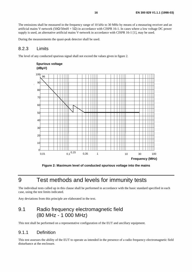
The emissions shall be measured in the frequency range of 10 kHz to 30 MHz by means of a measuring receiver and anartificial mains V-network (50Ω/50mH + 5Ω) in accordance with CISPR 16-1. In cases where a low voltage DC powersupply is used, an alternative artificial mains V-network in accordance with CISPR 16-1 [1], may be used.
During the measurements the quasi-peak detector shall be used.
8.2.3 Limits
The level of any conducted spurious signal shall not exceed the values given in figure 2.
10
20
30
40
50
60
70
80
00,01 0,1 1 10 100
100
300,15 0,35
90
96
Spurious voltage(dBµV)
Frequency (MHz)
Figure 2: Maximum level of conducted spurious voltage into the mains
9 Test methods and levels for immunity testsThe individual tests called up in this clause shall be performed in accordance with the basic standard specified in eachcase, using the test limits indicated.
Any deviations from this principle are elaborated in the text.
9.1 Radio frequency electromagnetic field(80 MHz - 1 000 MHz)
This test shall be performed on a representative configuration of the EUT and ancillary equipment.
9.1.1 Definition
This test assesses the ability of the EUT to operate as intended in the presence of a radio frequency electromagnetic fielddisturbance at the enclosure.
EN 300 829 V1.1.1 (1998-03)17
9.1.2 Test method
The EUT shall be subjected to the test corresponding to EN 61000-4-3 [8].
The RF-test level shall be 10 V/m swept over the frequency range 80 MHz to 1 GHz. The test signal shall be amplitudemodulated with 1 kHz and a modulation depth of 80 %.
The test shall be performed with the EUT in the receive mode of operation.
For narrow band responses, see subclause 4.2.
The test shall be repeated with the EUT in the transmit mode of operation.
9.1.3 Performance criteria
The performance criterion A (subclause 6.2) shall apply.
9.2 Electrostatic dischargeThis test shall be performed on a representative configuration of the EUT and ancillary equipment.
9.2.1 Definition
This test assesses the ability of the EUT to operate as intended in the event of ESDs.
9.2.2 Test method
The test generator, test set-up and test procedure shall be in accordance with EN 61000-4-2 [3].
For contact discharge, the equipment shall pass at ±2 kV and ±4 kV; for air discharge, the equipment shall pass at±2 kV, ±4 kV and ±8 kV.
The test shall be performed with the EUT in receive mode of operation.
The test shall be repeated with the EUT in transmit mode of operation.
9.2.3 Performance criteria
The performance criterion B (subclause 6.3) shall apply.
9.3 Fast transients, common mode
9.3.1 Definition
This test assesses the ability of the EUT to operate as intended in the event of fast transients/bursts on the power, signaland control ports.
9.3.2 Test method
The EUT shall be subject to the test in accordance with EN 61000-4-4 [5].
This test shall be performed on AC power ports.
This test shall be performed on signal and control ports and DC power ports (DC common mode only) when connectedto cables which may be longer than 3 m.

EN 300 829 V1.1.1 (1998-03)18
Where this test is not carried out on any port because the manufacturer user documentation states that it is not intendedto be used with cables longer than 3 m, a list of ports which were not tested for this reason shall be included in the testreport.
A test generator complying with subclause 6.1.1 of EN 61000-4-4 [5] shall be used. Application of the fast transientsignal shall be by a coupling/decoupling network complying with subclause 6.2 of EN 61000-4-4 [5] for AC/DC powerlines and a capacitive coupling clamp for signal and control lines complying with subclause 6.6.3 of EN 61000-4-4 [5].
The test level shall be 2 kV. The test voltage shall be applied as a 15 ms burst every 300 ms for the duration of3 minutes for each positive and negative polarity of the test voltage.
The test shall be performed with the EUT in receive mode of operation.
The test shall be repeated with the EUT in transmit mode of operation.
9.3.3 Performance criteria
The performance criterion B (subclause 6.3) shall apply.
9.4 RF common mode 150 kHz to 80 MHzIt is recognized that tests down to a frequency of 10 kHz (as called for in EN 60945 [13]) are an important requirement,however at this time there are no practical test methods available, hence here the lower frequency limit is set to 150 kHz.
This test shall be performed on AC power input ports.
This test shall be performed on signal and control ports and the DC power ports of the EUT connected to cables whichmay be longer than 3 m.
Where this test is not carried out on any port because the manufacturer user documentation states that it is not intendedto be used with cables longer than 2 m, a list of ports which were not tested for this reason shall be included in the testreport.
9.4.1 Definition
This test assesses the ability of the EUT to operate as intended in the presence of radio frequency electromagneticdisturbance.
9.4.2 Test method
This test shall be performed using the intrusive or direct connection method or the clamp injection method asappropriate (see EN 61000-4-6 [7]).
The following requirements shall apply:
- the test signal level shall be 3 V rms. unmodulated. The test signal shall then be amplitude modulated to a depthof 80 % by a sinusoidal audio signal of 1 kHz;
- the test shall be performed over the frequency range 150 kHz - 80 MHz;
- the stepped frequency increments shall be 50 kHz in the frequency range 150 kHz - 5 MHz and 1 % frequencyincrement of the momentary frequency in the frequency range 5 MHz - 80 MHz;
- to enable the best test method to be used an intrusive or direct connection can be made to any of the lines of anyinput/output port where it is practical and the performance of the equipment is not degraded, alternatively thecurrent clamp injection method can be used;
- the test method used shall be recorded in the test report.

EN 300 829 V1.1.1 (1998-03)19
Additionally a test shall be performed with a test level of 10 V emf at the following frequencies:
- 2 MHz;- 3 MHz;- 4 MHz;- 6,2 MHz;- 8,2 MHz;- 12,2 MHz;- 16,5 MHz;- 18,8 MHz;- 22 MHz; and- 25 MHz.
The test shall be performed with the EUT in receive mode of operation.
For narrowband responses, see subclause 4.2.
The test shall be repeated with the EUT in transmit mode of operation.
9.4.3 Performance criteria
The performance criterion A (subclause 6.2) shall apply.
9.5 Power supply short term variations
9.5.1 Definition
This test assesses the ability of the EUT to operate as intended when being subjected to power supply short termvariations present on the AC power input ports.
9.5.2 Test method
The test method shall be in accordance with EN 60945 [13]. The EUT shall be subject to the following power supplyvariations relative to the nominal value once per minute for the duration of 10 minutes each.
The nominal voltage shall be increased by 20 V ± 1 % for a duration of 1,5 s ± 0,2 s. Simultaneously the nominal ACsupply frequency shall be increased by 10 Hz ± 0,5 % for a duration of 5 s ± 0,5 s.
The test shall be repeated but with the nominal voltage decreased by 20 V ± 1 % for a duration of 1,5 s ± 0,2 s.Simultaneously the nominal AC supply frequency shall be decreased by 10 Hz ± 0,5 % for a duration of 5 s ± 0,5 s.
For both the above tests the voltage and frequency variation rise and decay times shall be 0,2 ± 0,1 s (at 10 % and90 %).
The test shall be performed with the EUT in the receive mode of operation.
The test shall be repeated with the EUT in the transmit mode of operation.
9.5.3 Performance criteria
The performance criterion B (subclause 6.3) shall apply.
9.6 Surge, common and differential modeThe test shall be performed on AC power input ports.
These tests shall be performed on a representative configuration of the EUT and ancillary equipment as appropriate.
EN 300 829 V1.1.1 (1998-03)20
9.6.1 Definition
These tests assesses the ability of the EUT and ancillary equipment to operate as intended in the event of surges on theAC mains power input ports.
9.6.2 Test method
The EUT shall be subject to the test corresponding to EN 61000-4-5 [6].
A combination wave (hybrid) generator complying with subclause 6.1 of EN 61000-4-5 [6] in combination with anycoupling/decoupling network complying with subclause 6.3 of EN 61000-4-5 [6] shall be used:
- the test level shall be 1 kV open circuit voltage for common mode and 0,5 kV open circuit voltage for differentialmode;
- the surges shall be applied (in parallel) to all the wires in the cable with reference to the cabinet reference ground,(true common mode), the series resistance shall be 10 Ω.
The test shall be performed with the EUT in receive mode of operation.
The test shall be repeated with the EUT in transmit mode of operation.
9.6.3 Performance criteria
The performance criterion B (subclause 6.3) shall apply.

EN 300 829 V1.1.1 (1998-03)21
Annex A (normative):Subclauses of the present document relevant forcompliance with the essential requirements of relevant ECCouncil Directives
Table A.1: Subclauses of the present document relevant for compliance with the essentialrequirements of the relevant EC Council Directives
Clause/Subclause number and title Corresponding article ofCouncil Directive 89/336/EEC
Qualifying remarks
8.1 Radiated emissions 4(a)8.2 Power ports 4(a)9.1 Radio frequency electromagnetic
field (80 MHz - 1 000 MHz)4(b)
9.2 Electrostatic discharge 4(b)9.3 Fast transients, common mode 4(b)9.4 RF common mode150 kHz to
80 MHz4(b)
9.5 Power supply short term variations 4(b)9.6 Surge, common and differential
mode4(b)
EN 300 829 V1.1.1 (1998-03)22
Annex B (informative):Alternative performance check (under investigation)It has been recognized that it is possible to carry out certain performance checks of Maritime Mobile Earth Stations(MMES) via satellite system, instead of the STE. At this time the operational impact of doing these performance checksare unclear and need further clarification. Therefore the contents of this annex are for information purposes only.
The performance check may be carried out without using the STE if messages are transmitted and received through thesatellite system.
The optimum solution would have been to use the important and vital function - distress alert transmission - in theperformance check. Using the distress alert would however cause some tests to be very difficult if not impossible tocarry out because of the protocol timing and the short bursts / packets used. Instead another vital function - the distressmessage transmission and reception - is currently used in the performance check. If the option to transmit and receivethrough the satellite system were introduced, it would be necessary to protect the integrity of the operational distresscommunication system. The messages transmitted and received would therefore be of normal priority only. Althoughthis is a further relaxation compared to using distress priority messages, it is found to be acceptable since the onlydifference between distress and normal priority messages in the Inmarsat-C system is a one bit and a two bits field in thesignalling to establish and close the protocol.
If the performance check were conducted through the satellite system instead of using the STE the followingrequirements would apply:
a) the performance check would be as described in subclause 6.4 except that all messages would be of normalpriority instead of distress priority;
b) the manufacturer would provide documentary evidence that the satellite system operator had accepted that theEUT transmits and receives messages through the satellite system;
c) when an antenna with active devices is placed outside the test premises for communication with the satellite, thisantenna would be tested separately as a stand alone unit. The magnitude of the transfer function(s) of the antennawould be measured before testing. This value would be required not to change more than +/-1 dB at any timeduring the test.
When not using the STE it would be necessary to ensure that no distress priority transmission to the satellite occurred.
EN 300 829 V1.1.1 (1998-03)23
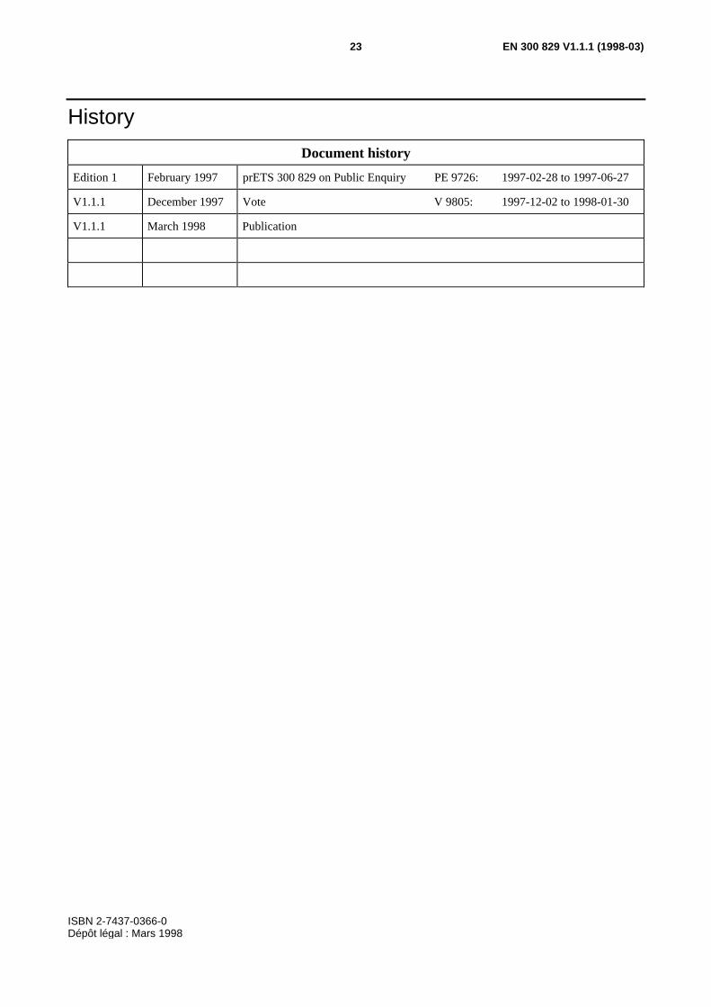
History
Document history
Edition 1 February 1997 prETS 300 829 on Public Enquiry PE 9726: 1997-02-28 to 1997-06-27
V1.1.1 December 1997 Vote V 9805: 1997-12-02 to 1998-01-30
V1.1.1 March 1998 Publication
ISBN 2-7437-0366-0Dépôt légal : Mars 1998