EN 1998-4: Eurocode 8: Design of structures for …EUROPEAN STANDARD NORME EUROPEENNE EUROpAISCHE...
83
EN 1998-4 (2006) (English): Eurocode 8: Design of structures for earthquake resistance – Part 4: Silos, tanks and pipelines [Authority: The European Union Per Regulation 305/2011, Directive 98/34/EC, Directive 2004/18/EC]
Transcript of EN 1998-4: Eurocode 8: Design of structures for …EUROPEAN STANDARD NORME EUROPEENNE EUROpAISCHE...

The European Union
In order to promote public education and public safety, equal justice for all, a better informed citizenry, the rule of law, world trade and world peace, this legal document is hereby made available on a noncommercial basis, as it is the right of all humans to know and speak the laws that govern them.
≠ EDICT OF GOVERNMENT ±
EN 1998-4 (2006) (English): Eurocode 8: Design of structuresfor earthquake resistance – Part 4: Silos, tanks andpipelines [Authority: The European Union Per Regulation305/2011, Directive 98/34/EC, Directive 2004/18/EC]


EUROPEAN STANDARD NORME EUROPEENNE
EUROpAISCHE NORM
EN 1998-4
July 2006
ICS 91.120.25 Supersedes ENV 1998-4:1998
English Version
Eurocode 8 - Design of structures for earthquake resistance -Part 4: Silos, tanks and pipelines
Eurocode 8 Calcul des structures pour leur resistance aux seismes Partie 4: Silos, reservoirs et canalisations
Eurocode 8 - Auslegung von Bauwerken gegen Erdbeben Teil4: Silos, Tankbauwerke und Rohrleitungen
This European Standard was approved by CEN on 15 May 2006.
CEN members are bound to comply with the CEN/CENELEC Internal Regulations which stipulate the conditions for giving this European Standard the status of a national standard without any alteration. Up-to-date lists and bibliographical references concerning such national standards may be obtained on application to the Central Secretariat or to any CEN member.
This European Standard exists in three official versions (English, French, German). A version in other language made by translation under the responsibility of a CEN member into its own language and notified to the Central <....:r>./~Y"'!tQYI"'t has the same status as the official versions.
CEN members are the national standards bodies of Austria, Belgium, Cyprus, Czech Republic, Denmark, Estonia, Finland, France, Germany, Greece, Hungary, Iceland, Ireland, Italy, Latvia, Lithuania, Luxembourg, Malta, Netherlands, Norway, Poland, Portugal, Romania, Slovakia, Slovenia, Spain, Sweden, Switzerland and United Kingdom.
EUROPEAN COMMITTEE FOR STANDARDIZATION COMITE EUROPEEN DE NORMALrSATION EUROpAiSCHES KOMITEE FUR NORMUNG
Management Centre: rue de Stassart, 36 B-1050 Brussels
2006 CEN All rights of exploitation in any form and by any means reserved worldwide for CEN national Members.
Ref. No. EN 1998-4:2006: E

EN 1998-4:2006 (E)
Contents
FOREWORD
GE,\, ER,4.t, ........................................................................................................................................ 8
1.1 SCOPE ........................................................................................................................................ 8 1..2 NORMATIVE REFERENCES .......................................................................................................... 9
1.2. 1 General sfandarc!\' ................................................................................................ 9 1.3 ASSUMPTIONS .......................................................................................................................... 1 () 1.4 DISTINCTION BETWEEN PRINCIPLES AND APPLICATIONS RULES ............................................... 10 1.5 TERI'v1S AND DI:FINITIONS ......................................................................................................... 10
1.6 1.7
1.5.1 General .......................................................... ..................................................................... 10 1.5.2 1.5.3 1.5.4
Term.,' common to all Ellrocodes ........................................................................................ 10 Further terms IIsed in EN 1998 .......................................................................................... 10 Further terms used in EN 1998-4 ....................................................................................... 10
SYf'v1BOLS ................................................................................................................................. 1.0 S.L UNITS ................................................................................................................................ 11
2 GENERAL PRINCIPLES AND APPLICATION RULES ......................................................... 13
2.1 2.1.1 2.1.2 2.1.3 2.1.4 2.1.5 2.1.6
SAFETY REQUiREMENTS ........................................................................................................... 13 General ............................................................................................................................... 13 Ultil11ate lin?it state ............................................................................................................. 13 Damage limitation state ..................................................................................................... 14 Reliability differentiation ................................................................................................... 15 System versus element reliahility .. ...................................................................................... 16 Conceptual .............................................................................................................. 16
2.2 2.3
2.4
2.3.1 2.3.2
SE1SI'v1JC ACTION ....................................................................................................................... 17 ANALYSIS ................................................................................................................................ 1.7
]vlethoc/s' ............................................................................................................ 1 7 interaction lvith the soil ........................... ........................................................................... 18
2.3.3 Dall1]Jing ........................................................ ..................................................................... 19 2.3.3.1 Structural daJllping .................................................................................................................. 19 2.3.3.2 Contents danlping .................................................................................................................... 19 2.3.3.3 Foundation 19 2.3.3.4 Weighted daI11ping ................................................................................................................... 19
BEHAVIOUR FACTORS .............................................................................................................. 19 2.5
2.5.1 SAFETY VERIFICATfONS ........................................................................................................... 20
General ............................................................................................................................... 20 2.5.2 COInbinations (~fseismic action l1'itl1 other actions ............................................................ 20
3 SP.ECIFICPRJNCIPLES AND APPLICATION RULES FOR SILOS .................................... 22
3.1 INTRODUCTION ........................................................................................................................ 22 3.2 COMBINATION OF GROUND MOTION COMPONENTS .................................................................. 22 3.3 ANALYSIS OF SILOS .................................................................................................................. 23 3.4 BEHAVIOUR FACTORS .............................................................................................................. 25 3.5 VERIFICATIONS ........................................................................................................................ 26
3.5.1 Damage limitation state ..................................................................................................... 26 3.5.2 Ultimate Ii/nit state ........................................................................................ , .. "" .............. 26
3.5.2.1 Global stability ........................................................................................................................ 26 3.5.2.2 Sbell ......................................................................................................................................... 26 3.5.2.3 Anchors ................................................................................................................................... 27 3.5.2.4 Foundations ............................................................................................................................. 27
4 SPECIFIC PRINCIPLES AND APPLICATION RULES FOR TANKS .................................. 28
4.] COMPLIANCE CRITERIA ............................................................................. , .............................. 28 4.1.1 General ........................................................................ ....................................................... 28 4.1.2 4.1.3
4.2
2
Danlage IiIJ1itation state ..................................................................................................... 28 Ultifnate lilnit state ............................................................................................................. 28
COMBINA TlON OF GROUND MOTION COMPONENTS .................................................................. 29

1998-4:2006 (E)
4.3
4.3.1 4.3.2
4.4
METHODS OF ANALYSIS ........................................................................................................... 29 General. .............................................................. ................................................................ 29 H,vdrodYrJc71l1ic ......................................................................................................... 29
BEHAVIOUR FACTORS .............................................................................................................. 30 4.5 VERIFICATIONS ........................................................................................................................ 31
4.5.1 Damage limitation state .. ................................................................................................... 3 J 4.5.1. J General .................................................................................................................................... 31 4.5.1.2 Shell ......................................................................................................................................... 31 4.5.1.3 Piping ...................................................................................................................................... 31
4.5.2 Ultill1ate liJnit state ............................................................................................................. 31 4.5.2.1 ................................................................................................................................... 31 4.5.2.2 Shell ......................................................................................................................................... 31 4.5.2.3 Piping ...................................................................................................................................... 32 4.5.2.4 A.nchorages .............................................................................................................................. 32 4.5.2.5 Foundations ............................................................................................................................. 32
4.6 COMPLEIV1ENTARY I\I[EASURES .................................................................................................. 32 4.6.1 32 4.6.2 33 4.6.3 Piping interaction ......................................................... ...................................................... 33
5 SPECIFIC PRINCIPLES AND APPLICATION RULES FOR ABOVE-GROUND PIPELINES 34
5.1 GENERAL ................................................................................................................................. 34 5.2
5.2.1 5.2.2
5.3
SAFETY REQUIREIV1ENTS ........................................................................................................... 34 Dalnage lilnitation state ..... ................................................................................................ 34 Ultilnate Iii-nit .vtate ............................................................................................................. 35
SEISIVlIC ACTION ....................................................................................................................... 35 5.3.1 5.3.2 5.3.3
General ................................................................... ............................................................ 35 Seismic action/oJ' inertia l11ovements ............................................................ ..................... 35 Differential movement .................................. ...................................................................... 35
5.4 5.4.1 5.4.2
5.5
METHODS OF ANALYSIS ........................................................................................................... 35 Modell ing ........................................................................................................................... 36 Analysis .............................................................................................................................. 36
BEHAVIOUR r ACTORS .............................................................................................................. 36 5.6 VERIFICATIONS ........................................................................................................................ 37
6 SPECIFIC PRINCIPLES AND APPLICATION RULES FOR BURIED PIPELINES .......... 38
6.1 GENERAL ................................................................................................................................. 38 6.2 SAFETY REQUiREMENTS ........................................................................................................... 38
6.2.1 limitation state ..................................................................................................... 38 6.2.2 Ultitnate IlInit state ............................................................................................................. 38
6.3 SEISMIC ACTION ....................................................................................................................... 38 6.3.1 General. .. , ........................................................... ................................................................ 38 6.3.2 Seismic actionfor inertia movements ............................................................. .................... 39 6.3.3 Modelling o.fseismic waves ................................................................................................ 39 6.3.4 Permanent soill11ovements ................................................................................................. 39
6.4 METHODS OF ANALYSIS (WAVE PASSAGE) ............................................................................... 40 6.5 VERIFTCATIONS ........................................................................................................................ 40
6.5.1 General ...... ......................................................................................................................... 4() 6.5.2 Buried pipeline.)' on stable soil .................................................................................. ......... 40 6.5.3 Buried pipelines under ground Ilu)'vements (welded steel pipe.s) ..................... 41
6.6 DESIGN MEASURES FOR FAULT CROSSINGS .............................................................................. 41
ANNEX A (INFORMATIVE) ................................................................................................................. 43
SEISMIC ANALYSIS PROCEDURES FOR TANKS ......................................................................... 43
ANNEX B (IN FORl\1i\ TIVE) ................................................................................................................. 79
BlTRIED PIPELINES .............................................................................................................................. 79
3

1998-4:2006 (E)
Foreword
This European Standard EN 1998-4, Eurocode 8: Design of structures for earthquake resistance: Silos, tanks and pipelines, has been prepared by Technical COlTIlTIittee CEN/TC 250 "Structural Eurocodes", the secretariat of which is held by BSI. CEN/TC 250 is responsible for all Structural Eurocodes.
This European Standard shall given the status of a National Standard, either by publication of an identical text or by endorsen1ent, at the latest by January 2007, and conflicting national standards shall be withdrawn at latest by March 2010.
This docunlent supersedes ENV 1998-4: 1997.
According to the CEN-CENELEC Internal Regulations, the National Standard Organizations of the following countries are bound to in1plen1ent this European Standard: Austria, Belgiunl, Cyprus, Czech Republic, Denmark, Estonia, Finland, France, Gennany, Greece, Hungary, iceland, Ireland, Italy, Latvia, Lithuania, LUXelTIbourg, Malta, Netherlands, Norway, Poland, Portugal, Slovakia, Slovenia, Spain, Sweden, Switzerland and United KingdOlTI.
Background of the Eurocode programme
In 1975, the C0l111TIission of the European ConllTIunity decided on an action progran1n1e in the field of construction, based on article 95 of the Treaty. The objective of the programn1e was the elilnination of technical obstacles to trade and the harn10nizatiol1 of technical specifications.
Within this action progran11TIe, the C0111mission took the initiative to establish a set of hannonized technical rules for the design of construction works which, in a first stage, would serve as an alternative to the national rules in force in the Member States and, ultimately, would replace then1.
For fifteen years, the Con1n1iss10n, with the help of a Steering Con1mittee with Representatives of Men1ber States, conducted the developn1ent of the Eurocodes progralnme, which led to the first generation of European codes in the 1980's.
In 1989, the Con1n11ssion and the Men1ber States of the and EFTA decided, on the basis of an agreement I between the C0111nlission and CEN, to transfer the preparation and the publication of the Eurocodes to through a series of Mandates, in order to provide thein with a future status of European Standard (EN). This links de facto the Eurocodes with the provisions of a]] the Council's Directives and/or Con1n1ission's Decisions dealing with European standards the Council Directive 8911 06/EEC on construction products - CPD and Council Directives 93/37/EEC, 921S0/EEC and 89/440lEEC on public works and services and equivalent EFTA Directives initiated in pursuit of setting up the internal l11arket).
The Structural Eurocode programnle c0111prises the following standards generally consisting of a nun1ber of Parts:
I Agreement between the Commission of the European Communities and the European Committee for Standardization (CE:-J) concerning the work on EUROCODES for the design of building and civil engineering works
4
EN 1998-4:2006 (E)
EN 1990 Eurocode: Basis of structural design
EN 1991 Eurocode 1: Actions on structures
EN 1992 Eurocode 2: Design of concrete structures
EN 1993 Eurocode 3: Design of steel stnlctures
EN 1994 Eurocode 4: Design of conlposite steel and concrete structures
EN 1995 Eurocode 5: Design of til11ber structures
EN 1996 Eurocode 6: Design of masonry structures
EN 1997 Eurocode 7: Geotechnical design
EN 1998 Eurocode 8: Design of structures for earthquake resistance
EN 1999 Eurocode 9: Design of alun1inium structures
Eurocode standards recognize the responsibility of regulatory authorities in each Menlber State and have safeguarded their right to determine values related to regulatory safety 111atters at national level where these continue to vary fro111 State to State.
Status and field of application of Eurocodes
The Mel11ber States of the EU and EFTA recognize that Eurocodes serve as reference docUlnents for the following purposes:
as a means to prove cOlnpliance of building and civil engineering works with the essential requirements of Council Directive 8911 06/EEC, particularly Essential Requirelnent N° 1 -Mechanical resistance and stability - and Essential Requirel11ent N°2 - Safety in case of fire;
as a basis for specifying contracts for construction works and related engineering services;
as a fran1e\vork for drawing up harmonized technical specifications for construction products (ENs and ETAs)
The Eurocodes, as far as they concern the construction works thelTIselves, have a direct relationship with the Interpretative Docun1ents2 refened to in Article 12 of the CPD, although they are of a different nature frOl11 harmonized product standards 3
. Therefore, technical
2 According to Art. 3.3 ofthe CPD, the essential requirements (ERs) shall be given concrete form in interpretative documents for the creation of the necessary links between the essential requirements and the mandates for hENs and ETAGs/ETAs.
According to Art. 12 of the CPD the interpretative documents shall :
a) give concrete form to the essential requirements by harmonising the terminology and the technical bases and indicating classes or levels for each requirement where necessary;
b) indicate methods of correlating these classes or levels of requirement with the technical specifications, e.g. methods of calculation and of proof, technical rules for project design, etR ;
c) serve as a reference for the establishment of hannonised standards and guidelines for European technical approvals.
The Eurocodes, de/acto, playa similar role in the field of the ER 1 and a part of ER 2.
5

EN 1998-4:2006 (E)
aspects arising fron1 the Eurocodes work need to be adequately considered by CEN Technical Con1nlittees and/or EOTA Working Groups working on product standards with a view to achieving a full cOll1patibility of these technical specifications with the Eurocodes.
The Eurocode standards provide conl1non structural design rules for everyday use for the design of whole structures and cOlnponent products of both a traditional and an innovative nature. Unusual f01111S of construction or design conditions are not specifically covered and additional expert consideration wi] I be required by the designer in such cases.
National Standards implementing Eurocodes
The National Standards ilnplelnenting Eurocodes will comprise the full text of the Eurocode (including any annexes), as published by CEN, which 111ay be preceded by a National title page and National foreword~ and may be followed by a National annex (informative).
The National annex may only contain infornlation on those parameters which are left open in the Eurocode for national choice, known as Nationally Deternlined Paranleters, to be used for the design of buildings and civil engineering works to be constructed in the country concerned, i.e. :
values and/or classes where alternatives are given in the Eurocode,
- values to be used where a syn1bol only is given in the Eurocode,
- country specific data (geographical, climatic, etc.), snow nlap,
- the procedure to be used where alternative procedures are given in the Eurocode.
It nlay also contain
decisions on the application of infonnative annexes,
references to non-contradictory conlplementary infonnation to assist the user to apply the Eurocode.
Links between Eurocodes and harmonized technical specifications (ENs and ETAs) for products
There is a need for consistency between the hannonized technical specifications for construction products and the technical rules for works4. Furthermore, all the infonnation accOlnpanying the CE Marking of the construction products which refer to Eurocodes shall clearly mention which Nationally Detenl1ined Parameters have been taken into account.
Additional information specific to EN 1998-4
The scope of EN 1998 is defined in 1.1.1 of EN 1998-1: 2004. The scope of this Part of 1998 is defined in 1.1. Additional Parts Eurocode 8 are listed in 1998-1: 2004, 1.1.3.
4 See ArL3.3 and Art.l2 of the as well as clauses 4.3.1,4.3.2 and 5.2 of ID 1.
6

EN 1998-4:2006 (E)
EN 1998-4:2006 is intended for use by:
- clients (e.g. for the fornlulation of their specific requiretnents on reliability levels and durability) ;
- designers and constructors;
- relevant authorities.
For the design of structures in seismic regions the provisions of this European Standard are to be applied in addition to the provisions of the other relevant parts of Eurocode 8 and the other relevant Eurocodes. In particular, the provisions of this European Standard conlplenlent those of EN 1991-4, EN 1992-3, EN 1993-4-1, EN 1993-4-2 and EN 1993-4-3, which do not cover the special requirenlents of seisnlic design.
National annex for EN 1998-4
This standard gives alternative procedures, values and recOlnnlendations for classes with notes indicating where national choices may have to be nlade. Therefore the National Standard ilnplelnenting EN 1998-4 should have a National Annex containing all Nationally Determined Parameters to be used for the design of buildings and civil engineering works to be constructed in the relevant country.
National choice is allowed in EN 1998-4:2006 through clauses:
Reference Item l.1(4) Additional requirelnents for facilities associated with large risks to the
population or the environnlent. 2.l.2( 4)P Reference return period TNCR of seislnic action for the ultinlate linlit
state (or, equivalently, reference probability of exceedance in SO years, PNCR ).
2.l.3(S)P Reference return period TDLR of seisnlic action for the danlage linlitation state (Of, equivalently, reference probability of exceedance in 10 years,
PDLf~)' 2.1.4(8) Inlportance factors for silos, tanks and pipelines 2.2(3) Reduction factor v for the effects of the seisnlic action relevant to the
dmnage linlitation state 2.3.3.3(2)P Maximum value of radiation damping for soil structure interaction
analysis, ?m<1x
2.S.2(3)P Values of (jJ for silos, tanks and pipelines 3. 1 (2)P Unit weight of the particulate solid in silos, y, In the seisnlic design
situation 4.S.l.3(3) Anlplification factor on forces transnlitted by the piping to region of
attachment on the tank wall, for the design of the region to remain elastic in the damage limitation state
4.S.2.3(2)P Overstrength factor on design resistance of piping in the verification that the connection of the piping to the tank will not yield prior to the piping in the ultimate limit state
7

EN 1998-4:2006 (E)
1 GENERAL
1.1 Scope
(l) The scope of Eurocode 8 is defined in 1998-1: 2004, 1.1.1 and the scope of this Standard is defined in this clause. Additional parts of Eurocode 8 are indicated in EN 1998-1: 2004, 1.1.3.
(2) This standard specifies principles and application rules for the seislnic design of the structural aspects of facilities conlposed of above-ground and buried pipeline systenls and of storage tanks of different types and uses, as well as for independent itenls, such as for exanlp]e single water towers serving a specific purpose or groups of silos enclosing granular ll1aterials, etc.
(3) This standard includes the additional criteria and rules required for the seisnlic design of these structures without restrictions on their size, structural types and other functional characteristics. For sonle types of tanks and silos, it also provides detailed methods of assessment and verification rules.
(4) This standard Inay not be cOlnplete for those facilities associated with large risks to the population or the environnlent, for which additional requirenlents are the responsibility of the conlpetent authorities. This standard is also not c0111plete for those construction works which have unconl1non structural elements and which require special nleasures to be taken and special studies to be performed to ensure earthquake protection. In those two cases the present standard gives general principles but not detailed application rules.
NOTE The National Annex may specify additional requirements for facilities associated with large risks to the population or the environment.
(5) Although large dianleter pipelines are within the scope of this standard, the corresponding design criteria do not apply for apparently sinlilar facilities, like tunnels and large underground cavities.
(6) The nature of lifeline systems which often characterizes the facilities covered by this standard requires concepts, nl0dels and methods that may differ substantially from those in CUITent use for 1110re common structural types. Furthermore, the response and the stability of silos and tanks subjected to strong seismic actions nlay involve rather cOlnplex interaction phenonlena between soil-structure and stored material (either fluid or granular), not easily amenable to sinlpljfied design procedures. Equally challenging may prove to be the design of a pipeline systenl through areas with poor and possibly unstable soils. For the reasons given above, the organization of this standard is to sonle extent different fronl that of other Parts of EN 1998. This standard is, in general, restricted to basic principles and nlethodological approaches.
NOTE Detailed analysis procedures going beyond basic principles and methodological approaches are given in Annexes A and B for a number of typical situations.
(7) In the fOll11ulation and implen1entation of the general requirenlents, a distinction has been made between independent structures and redundant systenls, via the choice of i111portance factors and/or through the definition of specific verification criteria.
8
EN 1998-4 :2006 (E)
(8) If SeiS111ic protection of above-ground pipelines is provided through seis111ic isolation devices between the pipeline and its supports (notably on piles), EN 1998-2:2005 applies, as relevant. For the design of tanks, silos, or individual facilities or conlponents of pipeline systems with seislnic isolation, the relevant provisions of 1998-1 :2004 apply.
1.2 Normative references
(l)P This European Standard incorporates by dated or undated reference, provisions fron1 other publications. These nOlmative references are cited at the appropriate places in the text and the publications are listed , For dated references, subsequent anlendnlents to or revisions of any of these publications apply to this European Standard only when incorporated in it by an1endnlent or revision, For undated references the latest edition of the publication referred to appJies (including an1endments),
1.2.1 General reference standards
EN 1990: 2002 Eurocode - Basis of structural de,)'ign.
EN 1991-4: 2006 EUl'ocode 1 Actions on structures Part 4: Silos and tanks.
EN 1992-1-1 : 2004 Eurocode 2 Design of concrete structures Part 1-1: General rules and rules for buildings,
EN 1992-3: 2006 Eurocode 2 - Design of concrete structures - Part 3: Liquid p'etaining and containing structures.
1993-1-1: 2004 Eurocode 3 - Design of steel structures Part 1-1: General rules and rules for buildings.
EN 1993-1-5: 2006 Eurocode 3 Design of steel structures Part elements.
. Plated structural
EN 1993-1-6: 2006 Eurocode 3 Design of steel strllctures - Part 1-6: Strength and stability of shell structures.
EN 1993-1-7: 2006 Ellrocode 3 - Design of steel structures - Part 1-7: Strength and stability of planar plated structures transversely loaded.
EN 1993-4-1: 2006 Eurocode 3 - Design of steel structures Part 4-1: Silos.
EN 1993-4-2: 2006 Eurocode 3 - Design of steel structures - Part . Tanks.
EN 1993-4-3: 2006 Eurocode 3 Design of steel structures - Part 4-3: Pipelines.
EN 1997-1 : 2004 Eurocode 7 - Geotechnical design - Part 1: General rules.
1998-1 : 2004 Eurocode 8 - Design of structures for earthquake resistance Part 1: General rules, seismic actions and rules for buildings.
EN 1998-2 : 2005 Eurocode 8 - Design of structures for earthquake resistance - Part 2: Bridges.
9

EN 1998-4:2006 (E)
EN 1998-5 : 2004 Eurocode 8 Design of structures for earthquake resistance - Part 5: Foundations, retaining structures and geotechnical aspects.
EN 1998-6 : 2005 Eurocode 8 - Design of structures for earthquake resistance Part 6: To H'ers , masts and chimneys.
1.3 Assumptions
(l)P The genera] aSSU111ptions shall be in accordance with EN 1990: 2002, 1.3.
1.4 Distinction between principles and applications rules
(l)P The distinction between principles and applications rules shall be in accordance with EN 1990: 2002, t.4.
1.5 Terms and Definitions
1.5. t General
(1) For the purposes of this standard the following definitions apply.
1.5.2 Terms common to aU Eurocodes
(l)P The ternlS and definitions given in EN 1990: 2002, 1.5 apply.
(2)P EN 1998-1: 2004, 1.5.1 applies for ten11S conlmon to an Eurocodes.
1.5.3 Further terms used in EN 1998
(1) F or the purposes of this European Standard the ten11S given in EN 1998-1: 2004, 1.5.1 and 1.5.2 apply.
1.5.4 Further terms used in EN 1998-4
Independent structure: a structure whose structural and functional behaviour during and after a seismic event are not influenced by that of other structures, and whose consequences of failure relate only to the functions detnanded fr0111 it.
1.6 Symbols
(1) For the purposes of this European Standard the following symbols apply:
AEd design value of seismic action ( = J1AEk)
A Ek characteristic value of the seisnlic action for the reference return period
b horizontal dimension of silo parallel to the horizontal component of the seisl11ic action
de inside dianleter of a circular silo
dg design ground displacelnent, as given in EN 1998-1 :2004, 3.2.2.4(1), used in expression (4.1 )
10
EN 1998-4:2006 (E)
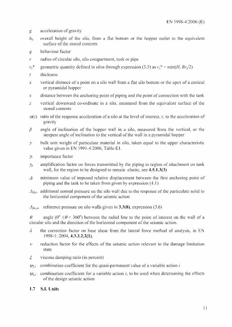
g acceleration of gravity
hb overall height of the silo, fron1 a flat bottonl or the hopper outlet to the equivalent surface of the stored contents
q behaviour factor
r radius of circular silo, silo C0111partment, tank or pipe
rs* geometric quantity defined in silos through expression (3.5) as r5 * n1in(H, Brsl2)
t thickness
x vertical distance of a point on a silo waH froll1 a flat silo bottom or the apex of a conical or pyralnidal hopper
x distance between the anchoring point of piping and the point of connection with the tank
z vertical downward co-ordinate in a silo, nleasured frOln the equivalent surface of the stored contents
a(z) ratio of the response acceleration of a silo at the level of interest, z, to the acceleration of gravity
/3 angle of inclination of the hopper wall in a silo, lTIeasured froll1 the vertical, or the steepest angle of inclination to the vertical of the wall in a pyramidal hopper
r bulk unit weight of particulate Inaterial in silo, taken equal to the upper characteristic value given in EN 1991-4:2006, Table E 1.
n importance factor
n) an1plification factor on forces transll1itted by the piping to region of attachnlent on tank wall, for the region to be designed to ren1ain elastic, see 4.5.1.3(3)
11 minimulTI value of imposed relative displacelnent between the first anchoring point of piping and the tank to be taken froln given by expression (4.1)
L1 ph,s additional nonnal pressure on the silo wall due to the response of the particulate solid to horizontal component of the seismic action
L1 ph ,so reference pressure on silo walls given in 3.3(8), expression (3.6)
f) angle (0° ~ f) < 360°) bet\veen the radial line to the point of interest on the wall of a circular silo and the direction of the horizontal component of the seislnic action.
A the correction factor on base shear from the lateral force Inethod of analysis, in EN 1998-1: 2004, 4.3.3.2.2(1).
v reduction factor for the effects of the seislnic action relevant to the dall1age limitation state
C; viscous dall1ping ratio (in percent)
1f/2.i cOlnbination coefficient for the quasi-permanent value of a variable action i
If/E,i combination coefficient for a variable action i, to be used when detern1ining the of the design seisn1ic action
1.7 S.1. Units
11

1998-4:2006 (E)
(l)P S. L Units shan be used in accordance with ISO 1000.
(2) In addition, the units recommended In 1998-1:2004, 1.7 apply.
12

EN 1998-4:2006 (E)
2 GENERAL PRINCIPLES AND APPLICATION RULES
2.1 Safety req uirements
2.1.1 General
(l)P This standard deals with structures which nlay differ \videly in such basic features as:
- the nature and anlount of the contents and associated potential danger
- the functional requirenlents during and after the seisnlic event
the enviro111nental conditions.
(2) Depending on the specific combination of the indicated features, different fornlulations of the general requirelnents are appropriate. For the sake of consistency with the general fralnework of the Eurocodes, the two-lilnit-states fornlat is retained, with a suitably adjusted definition.
2.1.2 Ultimate linlit state
(1)P The ultinlate lin1it state for which a systeln shall be checked is defined as that conesponding to structural failure. In sonle circUlnstances, partial recovery of the operational capacity of the system lost by exceedance of the uitinlate limit state may be possible, after an acceptable aillount of repairs.
NOTE 1: The circumstances are those defined by the responsible authority or the client.
(2)P For particular elenlents of the network, as well as for independent structures whose conlplete collapse would entail severe consequences, the ultilnate linlit state is defined as that of a state prior to sttuctural collapse that, although possibly severe, would exclude brittle failures and would allow for a controlled release of the contents. When the failure of the aforementioned eletnents does not entail severe consequences, the ultinlate hinit state may be defined as corresponding to total structural collapse.
(3)P The design seislnic action for which the ultimate linlit state ll1ay not be exceeded shall be established based on the direct and indirect consequences of stluctural failure.
(4)P The design seislnic action, shall be expressed in ternlS of: a) the reference SeiS111ic action, A Ek, associated with a reference probability of exceedance, PNCR, in 50 years or a reference retunl period, TNCR, (see EN 1998-1:2004, 2.1(1)P and 3.2.1(3)) and b) the importance factor n (see 1990:2002 and EN 1998-1:2004, 2.1(2)P, 2.1(3)P and (4)) to take into account reliability differentiation:
nAEk (2. t)
NOTE: The value 10 be ascribed to the reference retUlTI period, associated with the reterence seismic action for use in a country, may be found in its National Annex. The recommended value is: TNCR = 475 years.
(5) The capacity of structural systelns to resist seisnlic actions at the ultinlate lilnit state in
13
1998-4:2006 (E)
the non-linear range generally pen11its their design for resistance to seisnlic forces snlaller than those corresponding to a linear elastic response.
(6) To avoid explicit inelastic analysis in design, the capacity of the structural systems to dissipate energy, through n1ainly ductile behaviour of its elenlents and/or other 111echanisms, nlay be taken into account by perfonning a linear-elastic analysis based on a response spectrum reduced with respect to the elastic one, called "design spectrU111". This reduction is acconlplished by introducing the behaviour factor q, which is an approxilnation of the ratio of the seisn1ic forces that the structure would experience if its response was conlpletely elastic with 50/0 viscous danlping, to the seismic forces that may be used in the design, with a conventional linear-elastic analysis model, still ensuring a satisfactory perfornlance of the structural systenl at the uItinlate limit state.
(7) The values of the behaviour factor q, which also account for the influence of the viscous dmnping being different fr0111 50/0, are given for the various types of constructions covered by EN 1998-4 in the relevant Sections of this Eurocode.
2.1.3 Damage linlitation state
(l)P Depending on the characteristics and the purposes of the structure considered, a damage limitation state that meets one or both of the two following perfonnance levels nlay need to be satisfied:
'integrity' ;
'minilnunl operating level'.
(2)P In order to satisfy the 'integrity' requirenlent, the considered system, including a specified set of accessory elenlents integrated with it, shall rel11ain fully serviceable and leak proof under the relevant seislnic action.
(3)P To satisfy the 'mininlunl operating level' requirement, the extent and anl0unt of danlage of the considered system, including sonle of its components, shall be lilnited, so that, after the operations for dmnage checking and control are carried out, the capacity of the systel11 can be restored up to a predefined level of operation.
(4)P The seisillic action for which this limit state lTIay not be exceeded shall have an annual probability of exceedance whose value is to be established based on the following:
- the consequences of loss of function and/or of leakage of the content, and
the losses related to the reduced capacity of the systelTI and to the necessary repairs.
(5)P The SeiSlTIic action for which the 'daInage limitation' state Inay 110t be exceeded shall have a probability of exceedance, P OLR, in 10 years and a return period, TOLR. In the absence of nlore precise infornlatio11, the reduction factor applied on the design seismic action in accordance with 2.2(3) may be used to obtain the SeiSl11ic action for the verification of the danlage linlitatiol1 state.
NOTE: The values to be ascribed to or to TDLR for use in a country may be found in its National Annex of this docllment. The recommended values are P DLR 0% and TDLR 95 years.
14

EN 1998-4:2006 (E)
2.1.4 Reliability differentiation
(l)P Pipeline networks and independent structures, either tanks or silos, shall be provided with a level of protection proportioned to the number of people at risk and to the economic losses associated with their perfornlance level being not achieved.
(2)P Reliability differentiation shall be achieved by appropriately adjusting the value of the annual probability of exceedance of the design seislnic action.
(3) This adjustnlent should be inlplemented by classifying structures into different importance classes and applying to the reference seislnic action an inlportance factor )1,
defined in 2.1.2(4)P and in EN 1998-1: 2004, 2.1(3)P, the value of which depends on the inlportance class. Specific values of the factor )1, necessary to lnodify the action so as to correspond to a seismic event of selected return period, depend on the seisnlicity of each region. The value of the importance factor )1 = 1,0 is associated to the seisnlic action with the reference return period indicated in 2.1.2( 4)P.
NOTE For the dependence of the value of /1 see Note to EN 1998-1 :2004, 2.1(4)
(4) For the structures within the scope of this standard it is appropriate to consider three different inlportance classes, depending on the potential loss of life due to the failure of the particular structure and on the econonlic and social consequences of failure. Further classification may be nlade within each Inlportance depending on the use and contents of the facility and the ilnplications for public safety.
NOTE Importance classes I, II and HIIIV correspond CC3, respectively, defined in EN 1990:2002, Annex B.
to consequences classes CC 1, CC2 and
(5) Class I refers to situations where the risk to life is low and the econonlic and social consequences of failure are snlall or negligible.
(6) Situations with lnediunl risk to life and local econonl1C or social consequences of failure belong to Class II.
(7) Class III to situations with a high risk to life and large econonlic and social consequences of failure.
(8) Class IV refers to situations with exceptional risk to life and extrenle economic and social consequences of failure.
NOTE The values to be ascribed to YI for use in a country may be found in its National Annex. The values of Ji may be different for the various seismic zones of the country, depending on the seismic hazard conditions (see Note to EN 1998-1: 2.1 (4)) and on the public considerations detailed in 2.1.4. The value of J1 for importance class II by definition, equal to 1,0. For the other classes the recommended values of Yl are Yl = 0,8 for Importance Class I, Yl = 1.2 for importance class III and Yl = 1,6 for importance class IV,
(9)P A pipeline systelTI traversing a large geographical region normally encounters a wide variety of seismic hazards and soil conditions. In addition, a nunlber of subsysten1s nlay be located along a pipeline transmission systelTI, which nlay be either associated facilities (tanks, storage reservoirs etc.), or pipeline facilities (valves, PUlllPS, etc.). Under such circu111stances, critical stretches of the pipeline (for instance, less redundant parts of the system) and critica1
15
EN 1998-4:2006 (E)
C0J11pOnents (pUl1lpS, conlpressors, control equipment, etc.) shall be designed to provide larger reliability with regard to seisnlic events. Other conlponents, that are less essential and for which sonle danlage is acceptable, need 110t be designed to such stringent criteria.
2.1.5 System versus element reliability
(l)P The reliability requirenlents specified in 2.1.4 shall apply to the whole systenl under consideration, be it constituted by a single conlponent or by a set of conlponents variously connected to perfornl the functions required from it.
(2) Although a fornlal approach to system reliability analysis is outside the scope of this standard, the designer should give explicit consideration to the role played by the various elements in ensuring the continued operation of the systeln, especially when it is not redundant. In the case of very cOll1plex systelTIS the design should be based on sensitivity analyses.
(3)P ElelTIents of the network, or of a structure in the network, which are shown to be critical, with respect to the failure of the systenl, shall be provided with an additional margin of protection, commensurate with the consequences of the failure. When there is no previous experience, those critical elenlents shall be experinlentally investigated to verify the acceptability of the design assumptions.
(4) If more rigorous analyses are not undertaken, the additional nlm'gin of protection for critical elements nlay be achieved by assigning these elelnents to a class of reliability (expressed in ternlS of ltnportance Class) one level higher than that appropriate to the systeln as a whole. Alternatively the Capacity Design rules n1ay be used for the design of critica1 elenlents of a structure in the network, taking into account the actual resistance of elen1ents not considered as critica1.
2.1.6 Conceptual design
(l)P Even when the overall seismic response is specified to be elastic, structural elements shall be designed and detailed for local ductility and constructed fron1 ductile nlaterials.
(2)P The design of a network or of an independent structure shall take into consideration the following general aspects for nlitigation of earthquake effects:
- functional redundancy of the systems;
- absence of interaction of the nlechanical and electrical C01TIpOnents with the structural elements;
- easy access for inspection, 111aintenance and repair of damages;
quality control of the conlponents.
(3) In order to avoid spreading of da111age in functionally redundant systems due to structural interconnection of con1ponents, the appropriate parts should be functionally isolated.
(4) In case of in1portant facilities vulnerable to earthquakes, of which damage recovery is difficult or till1e consull1ing, replacement parts or subassenlblies should be provided.
16

EN 1998-4:2006 (E)
2.2 Seismic action
(l)P The SeiS111ic action to be used for the design of silos, tanks and pipelines shall be that defined in EN 1998-1 :2004, 3.2 in the various equivalent forn1s of site-dependent elastic response spectra (EN ] 998-1 :2004, 3.2.2), and tin1e-history representation (EN 1998-1 :2004, 3.2.3.1). Additional provisions for the spatial variation of ground n10tioll for buried pipelines are given in Section 6.
(2)P The seisn1ic action for which the ultin1ate li111it state shall be verified is specified in 2.1.2(4)P. If the detern1inatio11 of the seismic action effects is based on linear-elastic analysis with a behaviour factor q larger than 1 according to 1998-1 :2004, 3.2.2.5(2), the design spectrun1 for elastic analysis shall be used in accordance with EN 1998-1: 2004, 3.2.2.5 (see also 2.1.2(6)P).
(3) A reduction factor v may be applied to the design SeiS111ic action corresponding to the ultilnate limit state, to take into account the lower return period of the seis111ic action associated with the dan1age limitation state, as nlentioned in EN 1998-1:2004, 2.1 (1 )P. The value of the reduction factor v may also depend on the In1portance Class of the structure. Implicit in its use is the assu111ption that the elastic response spectrU111 of the SeiS111ic action under which the danlage limitation state should be verified has the san1e shape as the elastic response spectruln of the design seisnlic action corresponding to the uitin1ate lin1it state according to EN 1998-1 :2004, 2.1(1)P and 3.2.1 (3) (See EN 1998-1 :2004, 3.2.2.1(2) and 4.4.3.2(2) ).
NOTE The values to be ascribed to v for use in a cOllntry may be found in its National Annex. Different values of v may be defined for the various seismic zones of a country, depending on the seismic hazard conditions and on the protection of property objective. The recommended values of yare for importance classes I and II and v = 0,4 for importance classes III and IV. Different values may result from special zoning studies.
2.3 Analysis
2.3.1 Methods of analysis
(1) For the structures within the scope of this standard the seisnlic actions effects should be detern1ined on the basis of linear behaviour of the structures and of the soil in their vicinity.
(2) Nonlinear luethods of analysis may be used to obtain the seismic action effects for those special cases where consideration of nonlinear behaviour of the structure or of the surrounding soil is dictated by the nature of the problen1, or where the elastjc solution would be economically unfeasible.
(3)P Analysis for the evaluation of the effects of the seismic action relevant to the dan1age limitation state shall be linear-elastic, using the elastic spectra defined in 1998-1: 2004, 3.2.2.2 and 3.2.2.3, luultiplied by the reduction factor v refelTed to in 2.2(3). The elastic spectra should be entered with a \veighted average value of the viscous damping that takes into account the different danlping values of the different lnaterials/elements according to 2.3.5 and to EN 1998-1: 2004, 3.2.2.2(3).
(4) Analysis for the evaluation of the effects of the seisnlic action relevant to the ultitnate limit state may be linear-elastic in accordance with 2.1.2(6) and EN 1998-1:2004, 3.2.2.5,
17

EN 1998-4:2006 (E)
using the design spectra which are specified in EN 1998-1 :2004, 3.2.2.5 for a dalTIping ratio of 50/0. They 111ake use of the behaviour factor q to account for the capacity of the structure to dissipate energy, through ll1ainly ductile behaviour of its elelTIents and/or other lTIechanis111S, as well as the influence of viscous damping different from 5%(see also 2.1.2(6)P).
(5)P Unless otherwise specified for particular types of structures in the relevant parts of this standard, the types of analysis that nlay be applied are those indicated in EN 1998-1: 2004, 4.3.3, na111ely:
a) the' lateral force n1ethod' of (linear-elastic) analysis (see EN 1998-1 :2004, 4.3.3.2);
b) the 'lTIodal response spectrum ' (linear-elastic) analysis (see EN 1998-1 :2004, 4.3.3.3);
c) the non-linear static (pushover) analysis (see 1998-1 :2004, 4.3.3.4.2);
d) the non-linear tin1e history (dynaInic) analysis (see EN 1998-1 :20044.3.3.4.3).
(6)P Clauses 4.3.1(l)P, 4.3.1(2), 4.3.1(6), 4.3.1(7), 4.3.1(9)P, 4.3.3.1(5) and 4.3.3.1(6) of EN 1998-1 :2004 shall apply for the n10delling and analysis of the types of structures covered by the present standard.
(7) The' lateral force n1ethod' of linear-elastic analysis should be perfoll11ed according to
clauses 4.3.3.2.1(1)P, 4.3.3.2.2(1) (with A=l,O), 4.3.3.2.2(2) and 4.3.3.2.3(2)P EN 1998-1: 2004. It is appropriate for structures that respond to each cOlnponent of the SeiS111ic action approximately as a Single-Degree-of-Freedon1 systen1: rigid concrete) elevated tanks or silos on relatively flexible and alnl0st luass1ess supports.
(8) The 'lTIodal response spectrum' linear-elastic analysis should be perfornled according to Clauses 4.3.3.3.1(2)P, 4.3.3.3.1 (3), 4.3.3.3.1 (4) and 4.3.3.3.2 of EN 1998-1: 2004. It is appropriate for structures whose response is significantly affected by contributions from modes other than that of a Single-Degree-of-FreedOlu systen1 in each principal direction.
(9) Non-linear analysis, static (pushover) or dynamic (tin1e history), should satisfy EN 1998-1: 2004, 4.3.3.4.1.
(10) Non-linear static (pushover) analysis should be performed according to 4.3.3.4.2.2(1), 4.3.3.4.2.3, 4.3.3.4.2.6 of EN 1998-1 :2004.
(11) Non-linear dynan1ic (time history) analysis should satisfy EN 1998-1 :2004, 4.3.3.4.3.
(12) The relevant provisions of EN \998-1 :2004 apply to the analysis of tanks, silos and individual facilities or con1ponents of pipeline systen1s that are base isolated.
(13) The relevant provisions of EN 1998-2:2005 apply to the analysis of above-ground pipelines provided with seismic isolation devices between the pipeline and its supports.
2.3.2 Interaction with the soil
(1)P Soil-structure interaction effects shall addressed in accordance with 1998-5: 2004, Section 6.
NOTE Additional information on procedures for accounting for soil-structure interaction is presented in Informative Annex A, as well as in EN 1998-6:2005, Informative Annex C.
18
EN 1998-4:2006 (E)
2.3.3 Damping
2.3.3.1 Structural damping
(1) If the datnping values are not obtained froll1 specific infornlatioll, the following values of the dan1ping ratio should be used in linear analysis:
a) damage limitation state: the values specified in EN 1998-2:2005, 4.1.3(1);
b) ultimate lin1it state: ~ = 5%
2.3.3.2 Contents damping
(1) The value ~ = 0,5 % may be adopted for the daInping ratio of water and other liquids, unless otherwise deternlined.
NOTE: Reference to additional information for the determination of damping ratios of liquids is given in Informative Annex B.
(2) F or granular materials an appropriate value for the danlping ratio should be used. In the absence of more specific information a value of ~ 100/0 nlay be used.
2.3.3.3 Foundation damping
(l) Material daInping varies with the nature of the soil and the intensity shaking. When more accurate deternlinations are not available, the values given in Table 4.1 of EN 1998-5: 2004 ShOll Id be used.
(2)P Radiation daInping depends on the direction of motion (horizontal translation, vertical translation, rocking, etc .. ), on the geonletry of the foundation, on soil layering and soil morphology. The values adopted in the analysis shall be con1patible with actual site conditions and shall be justified with reference to acknowledged theoretical andlor experimental results. The values of the radiation daInping used in the analysis shall not exceed a maximunl value
NOTE: The value to be ascribed to for use in a country may be found in its National Annex. Guidance for the selection and use of damping values associated with different foundation motions is provided in EN 1998-6:2005. The recommended value i.s 25%.
2.3.3.4 Weighted damping
(1) The global average damping of the whole systenl should account for the contributions of the different tnaterials/elenlents to damping.
NOTE Procedures for accounting for the contributions of the different materials/elements to the globaJ average damping of the system are presented in EN 1998-2:2005, 4.1.3(1), Note and in EN 1998-6:2005, Informative Annex B.
2.4 Behaviour factors
(l)P For the danlage limitation state, the behaviour factor q shall be taken as equal to 1,0.
NOTE: For structures covered by this standard significant energy dissipation is not expected for the
19
EN 1998-4:2006 (E)
damage limitation state.
(2) Use of q factors greater than 1,5 in ultirnate linlit state verifications is only al1o\ved, provided that the sources of energy dissipation are explicitly identified and quantified and the capability of the structure to exploit thenl through appropriate detailing is de1110nstrated.
(3)P I f seismic protection is provided through seisl11ic isolation, the value of the behaviour factor at the ultinlate lin1it state shall be taken as not greater than q 1,5, except as provided in (4)P.
(4)P If seisll1ic protection is provided through seismic isolation, q shall be taken as equal to 1 for the fol1owing:
a) For the design of the substructure (i.e. of the elements below the plane of isolation).
b) For the part of the superstnlcture response of tanks which is due to the cOllvec6ve part of the liquid response (sloshing).
c) For the design of the isolators.
2.5 Safety verifications
2.5.1 General
(l)P Safety verifications shall be carried out for the lil11it states defined in 2.1, following the specific provisions in 3.5, 4.5, 5.6 and 6.5.
(2) If plate thickness is increased to account for future corrosion effects, the verifications should be n1ade for both the non-increased and the increased thickness. Analysis may be based on a single value of the plate thickness.
2.5.2 Combinations of seismic action with other actions
(l)P 'The design value Ed of the effects of actions in the seismic design situation shall be deternlined according to EN 1990: 2002, 6.4.3.4, and the inertial effects of the design seis111ic action shall be evaluated according to EN 1998-1 :2004, 3.2.4(2)P.
(2) In partial1y backfilled or buried tanks, permanent loads include, in addition to the weight of the structure, the weight of earth cover and any permanent external pressures due to ground\vater.
(3)P The conlbination coefficients ljI2,i (for the quasi-pel111anent value of variable action i) shall be those given in EN 1991-4. The conlbination coefficients ljIEi, introduced in EN 1998-I: 2004 3.2.4(2)P for the calculation of the effects of the seislnic actions, shall be taken as being equal to ljI2,i multiplied by a factor cp
NOTE: The values to be ascribed to rp for use in a country may be found in its National Annex. The recommended values of rp are rp = 1 for full silo, tank or pipeline and rp = 0 for empty silo, tank or pipeline.
(4)P The effects of the contents shall be considered in the variable loads for two levels of filling: enlpty or full. In batteries of silo or tank cells, different likely distributions of full and enlpty cells shall be considered according to the operation rules of the facility. At least, the design situations where all cells are either empty or full shall be considered. Only the
20

EN 1998-4:2006 (E)
syn1metrical filling loads of silos or silo cells shall be considered in the seismic design situation.
21

EN 1998-4:2006 (E)
3 SPECIFIC PRINCIPLES AND APPLICATION RULES FOR SILOS
3.1 Introduction
(1) A distinction is nlade between:
- silos directly supported on the ground or on the foundation, and
- elevated silos, supported on a skirt extending to the ground, or on a series of colLunns, braced or not.
The main effect of the seisnlic action on on-ground silos are the stresses induced in the shell wall due to the response of the contents of the silo (see (3) and 3.3(5) to (12) for the additional nornlal pressures on the shell walls). The nlain concern in the seismic design of elevated silos is the supporting structure and its ductility and energy dissipation capacity (see 3.4(4) and (5)).
(2)P The deternlination of the properties of the particulate solid stored in the silo, including its unit weight, y, shall be in accordance with EN 1991-4:2006, Section 4.
NOTE: The values to be ascribed to )' for use in a country in the seismic design situation may be found in its National Annex. For the stored materials listed in EN 1991-4:2006, Table El, the recommended value of i' is the upper characteristic value of unit weight )'lI specified in that table.
(3) Under seisnlic conditions, the pressure exerted by the particulate material on the walls, the hopper and the bOtt0111, 111ay increase over the value relative to the condition when there is no seisnl1c action. For design purposes this increased pressure is deenled to be found only from the inertia forces acting on the stored nlaterial due to the SeiS1Jlic action (see 3.3(5)).
(4)P The equivalent surface of the stored contents (as defined in EN 1991-4:2006, 1.5), in the seismic design situation shall be consistent with the value of the combination coefficients ~Jj~i used for the the calculation of the effects of the seisnlic actions in accordance with 2.5.2(3)P.
3.2 Combination of ground motion components
(1)P In axisynlnletric silos or parts therof, only one horizontal conlponent of the seislnic action may be taken to act together with the vertical conlponent. In all other cases, silos shall be designed for Sill1ultaneous action of the two horizontal conlponents and of the vertical component of the seismic action.
(2) When the structural response to each component of the seismic action is evaluated separately, EN1998-1 :2004, 4.3.3.5.2(4) ll1ay be applied for the detern1ination of the most unfavourable effect of the application of the simultaneous cOlnponents.
(3)P If expressions (4.20), (4.21), (4.22) in EN 1998-1 :2004, 4.3.3.5.2(4) are applied for the calculation of the action effects of the sinlultaneous components, the sign of the action effect due to each individual conlponent shall be taken as the nlost unfavourable for the particular action effect under consideration.
(4)P If the analysis is perfonned sin1ultaneously for the three cOlnponents of the seisnlic
EN 1998-4:2006 (E)
action using a spatial 1110del of the structure, the peak values of the total response under the combined action of the horizontal and vertical cOlnponents obtained fron1 the analysis shall be used in the structural verifications.
3.3 Analysis of si10s
(1) Analysis of silos should be accordance with 2.3 and 3.3.
(2)P The 1110del to be used for the detennination of the seisll1ic action effects shall reproduce accurately the stiffness, the Inass and the geOInetrical properties of the containment structure, shall account for the response of the contained particulate n1aterial and for the effects of any interaction with the foundation soil. The n10delling and analysis of steel si los shall be in accordance with EN 1993-4-1 :2006, Section 4.
(3)P Silos shall be analysed by considering elastic behaviour of the silo shell and of its supporting structure, if any, unless proper justification is given for perforn1ing a nonlinear analysis.
(4) Unless more accurate evaluations are undertaken, the global seisll1ic response and the seismic action effects in the supporting structure n1ay be calculated assunling that the particulate contents n10ve together with the silo shell and modelling them with their effective l11ass at their centre of gravity and its rotational inertia with respect to it. Unless a more accurate evaluation is nlade, the contents of the silo l11ay be taken to have an effective ll1ass equal to 80% of their total nlass.
(5) Unless the nlechanica1 properties and the dynanlic response of the particulate solid are explicitly and accurately accounted for in the analysis (e.g. by using finite elenlents to Inodel the mechanical properties and the dynamic response of the particu1ate solid), the effect on the shell of the response of the particulate solid to the horizontal con1ponent of the seisl11ic action
nlay be represented through an additiona1 nonnal pressure on the wall, Llph,s (positive for compression) specified in (6) to (10), under the conditions of (11) and (12). This additional pressure should be applied only over the part of the wall that is in contact with the stored contents, i.e. up to the equivalent surface of the stored contents, in the seisll1ic design situation (see 3.1(4)P).
(6) In circular silos (or silo compartn1ents) the additional normal pressure on the wall may be taken as equal to:
L1 ph,s= Llph,soCOS B (3.1)
where
L1ph,so is the reference pressure, see (8);
B is the angle (0° ~B < 360°) between the radial line to the point of interest on the wall and the direction of the horizontal component of the seisnlic action.
(7) In rectangular silos (or silo c0111partn1ents) ) the additional nonl1al pressure on the wall due to a horizontal cOlnponent of the seismic action parallel or nonnal to the silo walls n1ay be taken as equal to:
23

EN 1998-4:2006 (E)
On the' leeward' wall which is normal to the horizontal component of the SeiS1TIic action:
(3.2)
On the 'windward' wall which is nornlal to the horizontal C0111pOnent of the seisnlic action:
- Llph,so (3.3)
On the wa]]s which are parallel to the horizontal component of the seisnlic action:
(3.4)
(8) At points on the silo wall at a vertical distance x frOl11 a fIat bOttOlTI or the apex of a conical or pyranlidal hopper, the reference pressure nlay be taken as:
a(z)rnlin(rs *; 3x) (3.5)
where:
a(z) is the ratio of the response acceleration of the silo at a vertical distance z from the equivalent surface of the stored contents, to the acceleration of gravity;
r is the bulk unit weight of the particulate nlaterial in the seisll1ic design situation (see 3.1(1)P) and
rs* is defined as:
nlin(hb' dj2)
where:
(3.6)
hb is the overall height of the silo, frOl11 a flat bottonl or the hopper outlet to the equivalent surface of the stored contents, and
de is the inside dimension of the silo parallel to the horizontal component of the seismic action (inside diameter, de in circular silos or silo c0111partI11ents, inside horizontal dinlension b parallel to the horizontal component of the seismic action in rectangular ones).
(9) Expression (3.6) applies for vertical silo walls. Within the height of a hopper the reference pressure 111ay be taken as:
= a(z)rnlin(rs*; 3x)/cosfJ (3.7)
where:
fJ is the of inclination of the hopper wall, 111easured from the vertical, or the steepest angle of inclination to the vertical of the wall in a pyranlidal hopper.
(l0) If only the value of the response acceleration at the centre of gravity of the particulate nlaterial is available (see, (4) and 2.3.1(7)) the corresponding ratio of response acceleration to the acceleration of gravity 111ay be used in expression (3.7) for a(z).
(11)P At any point on the silo wall the sunl of the static pressure of the particulate material on the wall and of the seisnlic action effect, shall not be taken less than zero.
24

(12) If at any location 011 the silo wall the SUln of
Llph,s given by (6) to (to) and expressions (3.1) to (3.3) and the static pressure of the particulate nlaterial on the wall
EN 1998-4:2006 (E)
is negative (ilnplying net suction on the wall), then (6) or (7) nlay not be considered to apply. In that case, the additional nonnal pressures on the wall, Llph,s, should be redistributed to ensure that their sunl with the static pressure of the particulate material on the wall is everywhere non-negative, while maintaining the saIne force resultant over the same horizontal plane as the values of given in (6) or (7).
3.4 Behaviour factors
(1)P Non-base-isolated silos shall be designed according to one of the following concepts (see EN 1998-1 :2004, 5.2.1, 6.1.2, 7.1.2):
a) low-dissipative structural behaviour;
b) dissipative structural behaviour.
(2) In concept a) the seislnic action effects nlay be calculated on the basis of an elastic global analysis without taking into account significant non-linear nlaterial behaviour. When using the design spectnun defined in EN 1998-1 :2004, 3.2.2.5, the value of the behaviour factor q Inay be taken up to 1,5. Design according to concept a) is ternled design for ductility class Low (DCL). Selection of nlaterials, evaluation of resistance and detailing of ll1embers and connections should be as specified in EN 1998-1 :2004, Section 5 to 7, for ducti Iity class Low (DCL).
(3) Silos directly supported on the ground or 011 the foundation should be designed according to concept a) and (2).
(4) Concept b) Inay be applied to elevated silos, According to this concept, the capabi lity of parts of the supporting structure to resist earthquake actions beyond their elastic range (lts dissipative zones), is taken into account. Supporting structures designed according to this concept should belong to ductility class Medium (OCM) or High (DCH) defined and described in EN 1998-1: 2004, Section 5 to 7, depending on the structural Inaterial of the supporting structure. They should meet the requirenlents specified therein regarding structural type, Inaterials and dinlensioning and detailing of melnbers or connections for ductility_ When using the design spectrUl11 for linear-elastic analysis defined in EN 1998-1 :2004, 3.2.2.5, the behaviour factor q Inay be taken as being greater than 1 The value of q depends on the selected ductility class (DCM or DCB).
(5) Due to the litnited redundancy, the high axial forces due to the weight of the silo contents and the absence of non-structural elelnents contributing to earthquake resistance and energy dissipation, the energy dissipation capacity of the structural types cOlnnl0nJy used to support elevated silos is, in general, less than that of a sin1ilar structural type when used in buildings. Therefore, in concept b) the upper Jinlit value of the q factors for elevated silos are defined in tenl1S of the q factors specified in 1998-1 :2004, Sections 5 to 7, for the selected ductility class (OCM or OCH), as follows:
- For skirt-supported silos, with the skirt designed and detailed to ensure dissipative behaviour; the upper limit values of the q factor defined in EN 1998-1: 2004, Sections 5 to
25

EN 1998-4:2006 (E)
7 for inverted pendulu111 structures may be used. If the skirt is not detailed for dissipative behaviour, it should be designed according to concept a) and (2).
For silos supported on monlent resisting fratnes or on franles with bracings, and for castin-place concrete silos supported on concrete walls which are continuous to the foundation, the upper linlit of the q factors are those defined for the cOlTesponding structural systenl in EN 1998-1:2004, Sections 5 to 7, tinles a factor equal to 0,7 for irregularity in elevation.
3.5 Verifications
3.5.1 Damage limitation state
(l)P In the seismic design situation relevant to the daInage limitation state the silo structure shall be checked to satisfy the relevant serviceability linlit state verifications required by EN 1992-1-1, EN 1992-3 and EN 1993-4-1.
NOTE: For steel silos, adequate reliability with respect 10 the occurrence of elastic or inelastic buckling phenomena is considered to be provided in the seismic design situation relevant to the limitatiol1 state, if the verifications regarding these phenomena are satisfled under the seismic situation for the ultimate limit state.
3.5.2 Ultimate limit state
3.5.2.1 Global stability
(I)P Overturning or bearing capacity failure of the soil shall not occur in the seismic design situation. The resisting shear force at the interface of the base of the structure and the foundation, shall be evaluated taking into account the effects of the vertical C0111pOnent of the seisnl1c action. Limited sliding may be acceptable, if it is demonstrated that the inlplications of sliding for the connections between the various parts of the structure and bet\veen the structure and any piping are taken into account in the analysis and the verjfications (see also EN 1998-5: 2004, 5.4.1.1(7)).
(2)P For uplift of on-ground silos to be considered acceptable, it shall be taken into account in the analysis and in the subsequent verifications of the structure, of any piping and of the foundation in the assessnlent of overall stability).
3.5.2.2 Shell
(l)P The ll1axinlU1n action effects (nlelnbrane forces and bending mOlnents, circmnferential or nleridional, and ll1elllbrane shear) induced in the seislnic design situation shall be less or equal to the resistance of the shell evaluated as in the persistent or transient design situations. This includes all types of failure Inodes.
(a) For steel shells:
yieJding (plastic collapse),
buckling in shear, or
26

EN 1998-4:2006 (E)
- buckling by vertical con1pression with sin1ultaneous transverse tension ("elephant foot' mode of failure), etc.
(see EN 1993-4-1 :2006, Sections 5 to 9).
(b) For concrete shells:
- the ULS in bending with axial force,
- the ULS in shear for in-plane or radial shear, etc.
(2)P The calculation of resistances and the verifications shall be carried out in accordance with EN 1992-1-1, EN 1992-3, EN 1993-1-1, EN 1993-1-5, EN 1993-1-6, EN 1993-1-7 and EN 1993-4-1.
3.5.2.3 Anchors
(l)P Anchoring systems shall generally be designed to relnain elastic in the seismic design situation. However, they shall also be provided with sufficient ductility, so as to avoid brittle failures. The connection of anchoring elements to the structure and to its foundation shall have an overstrength factor of not less than 1,25 with respect to the resistance of the anchoring e1elnents.
(2) If the anchoring system is part of the dissipative n1echanisms, then it should be verified that it possesses the necessary ductility capacity.
3.5.2.4 Foundations
(l)P The foundation shall be verified according to EN 1998-5:2004,5.4 and to EN 1997-1.
(2)P The action effects for the verification of the foundation and of the foundation elen1ents shall be derived in accordance with EN 1998-5 :2004, 5.3.1, EN 1998-1 :2004, 4.4.2.6 and 5.8.
27

EN 1998-4:2006 (E)
4 SPECIFIC PRINCIPLES AND APPLICATION RULES FOR TANKS
4.1 Compliance criteria
4.1.1 General
(l)P The general requirelnents specified in 2.1 are deen1ed to be satisfied if, in addition to the verifications specified in 4.4, tanks conforn1 to the con1plen1entary n1easures specified in 4.5.
(2) The con1pliance criteria and application rules given in this Section do not fully cover the case of steel tanks with t10ating roofs.
NOTE: Special attention is needed to avoid damage to the shell due to local effects of the impact by the floating roof. Such effects may calise a fire in tanks \vith combustible contents.
4.1.2 Damage limitation state
(l)P In order to satisfy the 'integrity' requiren1ent under the seisnlic action relevant to the damage lilTIitation state:
Leak tightness of the tank system shall be verified;
adequate freeboard shall be provided in the tank under the Inaxin1um vertical displacen1ent of the liquid surface, in order to prevent damage to the roof due to the pressure of the sloshing liquid or, if the tank has no rigid roof, to prevent undesirable effects of spilling of the liquid;
- the hydraulic systenls which are part of, or are connected to the tank, shall be verified to accon11110date stresses and distortions due to relative displacements between tanks or between tanks and soil, without their functions being impaired.
(2)P In order to satisfy the 'lninimUlTI operating level' requirelnent under the SeiS111ic action relevant to the danlage 1in1itation state, it shall be verified that local buckling, if it occurs, does not trigger collapse and is reversible.
4.1.3 Ultimate limit state
(l)P The following conditions shall be verified in the seismic design situation:
The overall stability of the tank shall be verified in accordance with EN 1998-1: 2004, 4.4.2.4. The overall stability refers to rigid body behaviour and ll1ay be in1paired by sliding or overturning. A lin1ited aInount of sliding may be accepted in accordance with EN 1998-5: 2004, 5.4.1.1(7), if tolerated by the pipe system and if the tank is not anchored to the foundation.
Inelastic behaviour is restricted to well-defined parts of the tank, in accordance with the provisions of the present standard.
The ultill1ate defonnations of the nlaterials are not exceeded.
28
1998-4:2006 (E)
The nature and the extent of buckling phenOluena in the shell are controlled according to the relevant verifications.
The hydraulic systems which are part of, or connected to the tank are designed so as to prevent loss of the contents of the tank in the event of failure of any of its components.
4.2 Combination of ground motion components
(l)P Tanks shall confornl to 3.2(l)P.
(2) Tanks should conform to 3.2(2).
(3)P Tanks shall conform to 3.2(3)P.
4.3 Methods of analysis
4.3.1 General
(l)P The 1110del to be used for the deternlination of the seismic efIects shall reproduce properly the stiffness, the strength, the daIuping, the nlass and the geometrical properties of the containnlent structure, and shall account for the hydrodynanlic response of the contained liquid and, where necessary, for the effects of interaction with the foundation soil.
NOTE The parameters of soil-liquid-structure-interaction may have a significant inlluence on the natural frequencies and the radiation damping in the soil. With increasing shear wave velocity of the soil, the vibration behaviour changes from a horizontal vibration combined with rocking influenced by the soil to the typical vibration mode of a tank on rigid soil. For highly stressed tank structures or for the case of dangerous goods a global (three-dimensional) may be necessary.
(2) Tanks should be generally analysed assunling linear elastic response. In particular cases nonlinear response Inay be justified by appropriate Inethods of analysis.
NOTE Information on methods for seismic analysis of tanks of usual shapes is provided in Informative Annex A.
(3) Possible interaction between different tanks due to connecting plpmg should be considered whenever relevant.
4.3.2 Hydrodynamic effects
(l)P A rational nlethod based on the solution of the hydrodynanlic equations with the appropriate boundary conditions shall be used for the evaluation of the response of the tank systenl to the seismic action.
(2)P In particular, the analysis shall properly account for the following, where relevant:
the convective and the inlpulsive components of the motion of the liquid;
the defolmation of the tank shell due to the hydrodynamic pressures and the interaction effects with the ilnpulsive conlponent;
the defomlabi1ity of the foundation soil and the ensuing modification of the response
29

EN 1998-4:2006 (E)
- the efTects of a floating roof, if relevant.
(3) For the purpose of evaluating the dynmTIic response under seismic actions, the liquid nlay be generally assumed as incompressible.
(4) Deternlination of the lTIaxinlUm hydrodynanlic pressures induced by horizontal and vertical excitation requires, in principle, use of nonlinear dYl1atl1ic (tinle-history) analysis. Sinlplified nlethods allowing for a direct application of the response spectrunl analysis nlay be used, provided that suitable conservative rules for the conlbination of the peak lTIodal contributions are adopted.
NOTE Informative Annex A information on acceptable procedures for the combination of the peak modal contributions in response spectrum It also gives expressions for the calculation of the sloshing wave height
4.4 Behaviour factors
(1)P Tanks of type other than those nlentioned in (4)P and (5) shall be either designed for elastic response (q up to 1,5, accounting for overstrength), or, in properly justified cases, for inelastic response (see 2.3.1(2»), provided that it is denlonstrated that inelastic response is acceptable.
(2)P The energy dissipation cOlTesponding to the selected value of q shall be properly substantiated and the necessary ductility provided through ductile design.
(3)P The convective part of the liquid response (sloshing) shall always be evaluated on the basis of elastic response (i .e. with q = 1,0) and of the associated spectra (see EN 1998-1: 2004, 3.2.2.2 and 3.2.2.3).
(4) The behaviour factors specified in 3.4 should be applied also to the part of the response of elevated tanks which is not due to sloshing of the liquid. For that part, the rules specified in 3.4(4) for skirt-supported silos apply also to elevated tanks on a single pedestal.
(5) Steel tanks (unless base-isolated) which have a vertical axis and are supported directly on the ground or on the foundation, nlay be designed with a behaviour factor q greater than I subject to the following:
- the part of the response which is due to sloshing of the liquid, should be taken with q 1,0.
the tank or its foundation is designed to allow uplift andlor sliding
- localisation of plastic defomlations in the shell wall, the bOtt0111 plate or their intersection is prevented.
Under these conditions, the behaviour factor q 11lay be taken as not larger than the following values, unless the inelastic response is evaluated by a more refined approach:
2,0 for unanchored tanks, provided that the design rules of EN 1993-4-2:2006 are fulfilled, especially those concerning the thickness of the bottom plate, which should be less than the thickness of the lower part of the shell.
30

EN 1998-4:2006 (E)
2,5 for tanks with specially designed ductile anchors allowing an increase in anchor length without rupture equal to R1200, where R is the tank radius.
4.5 Verifications
4.5.1 Damage limitation state
4.5.1.1 General
(l)P Under the seisnlic action relevant to the damage linlitation state, the tank structure shall satisfy the serviceability lilnit state verifications specified in EN 1992-3 and EN 1993-4-2, as relevant.
4.5.1.2 Shell
4.5.1.2.1 Reinforced and prestressed concrete shells
(1) Under the seismic action relevant to the damage limitation state, crack widths should be verified against the limit values specified in EN 1992-1-1: 2004, 4.4.2, taking into account the appropriate environlnental exposure class and the sensitivity of the steel to corrosion.
(2) In case of lined concrete tanks, transient concrete crack widths should not exceed a value that might induce local defornlation in the liner exceeding 500/0 of its ultinlate uniform elongation.
4.5.1.2.2 Steel shells
(1) Steel tanks should confonn to 3.5.1(2).
4.5.1.3 Piping
(1) Unless special requirenlents are specified for active on-line conlponents, such as valves or PU111PS, piping does not need to be verified for the damage liInitation state.
(2)P Relative displacenlents due to differential seislnic nlovenlents of the ground shal1 be accounted for, if the piping and the tank(s) are supported on different foundations.
(3) The region of the tank where the piping is attached to should be designed to ren1ain
elastic under the forces translnitted by the piping amplified by a factor n) 1·
NOTE The value to be ascribed to the amplification factor X)I for use in a country, may be t()Und in its National Annex. The recommended value is: J1)1 = 1,3.
4.5.2 Ultimate limit state
4.5.2.1 Stability
(I)P Tanks sha1l conforn1 to 3.5.2.1(1)P.
(2)P Tanks sha1l confonn to 3.5.2.1(2)P.
4.5.2.2 Shell
3 ]

EN 1998-4:2006 (E)
(I)P Tanks shall conforn1 to 3.5.2.2(1 )P.
NOTE information for the ultimate strength capacity of the shell, as controlled by variolls failure modes, is given in Informative Annex A.
4.5.2.3 Piping
(1) If reliable data are not available or more accurate analyses are not n1ade, a relative displacen1ent between the first anchoring point of the piping and the tank should be postulated to take place in the n10st adverse direction, with a n1ininlum value of:
(4.1) xo
where:
x distance between the anchoring point of the piping and the point of connection with the tank (in meters);
Xo = 500 n1; and
dg = design ground displacement as given in EN 1998-1: 2004, 3.2.2.4(1).
(2)P It shall be verified that in the seisnlic design situation, including the postulated relative displacements of (1), yielding is restricted to the piping and does not extend to its connection to the tank, even when an overstrength factor rp2 on the design resistance of the piping is taken into account.
NOTE The value to be ascribed to the overstrength factor ii1~ for Llse in a country, may be found in its National Annex. The recommended value is: ii)2
(3)P The design resistance of piping elements shall be evaluated as in the persistent or transient design situations.
4.5.2.4 Anchorages
(1)P Tanks shall confonn to 3.5.2.3(1)P.
4.5.2.5 Foundations
(l)P Tanks shall confornl to 3.5.2.4(l)P.
(2)P Tanks shall confornl to 3.5.2.4(2)P.
4.6 Conlplementary measures
4.6.1 Bunding
(1)P Tanks, single or in groups, which are designed to control or avoid leakage in order to prevent fire, explosions and release of toxic nlaterials shall be bunded (i.e. shall be surrounded by a ditch and/or an e1TJbanknlent).
(2)P If tanks are built in groups, bunding may be provided either to every individual tank or
32
EN 1998-4:2006 (E)
to the whole group. If the consequences associated with potential failure of the bund are considered to be severe, individual bunding shall be used.
(3)P The bunding shall be designed to retain its full integrity (absence of leaks) under the design seislnic action relevant to the ultinlate linlit state of the enclosed systenl.
4.6.2 Sloshing
(l)P In the absence of explicit justifications (see 4.1.2(1)P), a freeboard shall be provided having a height not less than the calculated height of the slosh waves.
NOTE: Information on procedures to determine the sloshing ,,\/ave height are presented in Informative AnnexA.
(2)P Freeboard at least equal to the calculated height of the slosh waves shall be provided, if the contents are toxic, or if spilling could cause danlage to piping or scouring of the foundation.
(3) Freeboard less than the calculated height of the slosh waves may be sufficient, jf the roof is designed for the associated uplift pressure or if an overflow spillway is provided to control spilling.
(4) Damping devices, as for exanlple grillages or vertical partitions, lnay be used to reduce sloshing.
4.6.3 Piping interaction
(l)P The piping shall be designed to miniInize unfavourable effects of interaction between tanks and between tanks and other structures.
33

1998-4:2006 (E)
5 SPECIFIC PRINCIPLES AND APPLICATION RULES FOR ABOVE-GROUND PIPELINES
5.1 General
(I) This section ain1s at providing principles and application rules for the SeiSll1ic design of the structural aspects of above-ground pipeline systenls. This section may also be used as a basis for evaluating the resistance of existing above-ground piping and to assess any required strengthening.
(2) The SeiSll1ic design of an above-ground pipeline cOlnprises the establishnlent of the location and characteristics of the supports in order to lilnit the strain in the piping components and to 1ilnit the loads applied to the equipn1ent located on the pipeline, such as valves, tanks, pun1ps or instrunlentation. Those lin1its are not defined in this standard and should be provided by the owner of the facility or the manufacturer of the equiplnent.
(3) Pipeline syste111S usually cOlTIprise several associated facilities, such as pumping stations, operation centres, 111aintenance stations, etc., each of thenl housing different types of 111echanical and electrical equipnlent. Since these facilities have a considerable influence on the continued operation of the system, it is necessary to give thenl adequate consideration in the seisnlic design process aimed at satisfying the overall reliability requirenlents. Explicit treatnlent of these facilities, however, is not within the scope of this standard. In fact, son1e of those facilities are covered in EN 1998-1, while the seismic design of mechanical and electrical equipll1ent requires additional specific criteria that are beyond the scope of Eurocode 8 (see 1.1(8) for the seismic protection of individual facilities or components of pipeline systen1s through SeiS111ic isolation).
(4)P For the formulation of the genera] requirements to follow, as well as for their implenlentation, pipeline systen1s shall be distinguished as follows:
single lInes
redundant networks.
(5)P A pipeline shall be considered as a single line when its behaviour during and after a SeiS111ic event is not influenced by that of other pipelines, and if the consequences of its failure relate only to the functions denlanded from it.
5.2 Safety requirements
5.2.1 Damage limitation state
(I)P Pipeline systelTIS shall be constructed in such a way as to be able to n1aintain their supplying capability as a global servicing system, after the seismic action relevant to the 'nlininlun1 operating level' (see 2.1.3), even with considerable local damage.
(2) A global deformation of the piping not greater than 1,5 tin1es its yield defonnation is acceptable, provided that there is no risk of buckling and the loads applied to active equipnlent, such as valves, pun1ps, etc., are within its operating range.
34

EN 1998-4:2006 (E)
5.2.2 U Jtimate lintit state
(l)P The lTIaill safety hazard directly associated with the pipeline rupture during a seismic event is explosion and fire, particularly with regard to gas pipelines. renloteness of the location and the exposure of the population to the ilTIpact of rupture shall be taken into account in establishing the level of the seisnlic action relevant to the ultimate limit state.
(2)P For pipeline systenls in environnlentally sensitive areas, the danlage to the environlnent due to pipeline ruptures shall also be taken into account in the definition of the acceptable risk.
5.3 Seismic action
5.3.1 General
(l)P The following direct and indirect seismic hazard types are relevant for the seisll1ic design of above-ground pipeline systelns:
- Movenlent due to the inertia of the pipelines induced by the seislnic lTIOVenlent applied to their supports.
- DifferentiallTIovelnent of the supports of the pipelines.
(2) For differential 1110vement of supports two different situations may exist:
For supports which are directly on the ground, significant differential 1110venlent IS
possible only if there are soil failures and/or permanent defonnations
For supports which are located on different structures, the selsnllC response of the structure may create differential nlovelnents on the pipeline;
5.3.2 Seislnic action for inertia movements
(l)P The quantification of the horizontal components of the seisnlic action shall be carried out in terms of the response spectruln (or a cOlTIpatible tinle history representation) as specified in EN 1998-1: 2004, 3.2.2.
(2) Only the three translational cOlllponents of the seislnic action should be taken into account (i.e., the rotational components lTIay be neglected).
5.3.3 Differential movement
(1) When the pipeline is supported directly on the ground, the differential nlovenlent 111ay be neglected, except when soil failures or pennanent defonl1ations are likely to occur. In that case the atnplitude of the 1110velnent should be evaluated with appropriate techniques.
(2) When the pipeline is supported on different structures, their differentlal movelnent should be defined frOlTI their seismic response analysis or by silnplified envelope approaches.
5.4 Methods of analysis
35
EN 1998-4:2006 (E)
5.4.1 l\tlodelling
(l)P The model of the pipeline shall be able to represent the stiffness1 the dan1ping and the 111ass properties, as well as the dynanl1c degrees of freedolTI of the systenl, with explicit consideration of the following aspects, as appropriate:
tlexibility of the foundation soil and foundation systelTI;
- lTIaSS of the tluid inside the pipeline;
- dynamic characteristics of the supporting structures;
- type of connection between pipeline and supporting structure;
- joints along the pipeline and between the supports.
5.4.2 Analysis
(1) Above ground pipelines nlay be analysed by means of the 1110da] response spectrUlTI analysis with the associated design response spectrmTI as given in EN 1998-1: 2004, 3.2.2.5., c0l11bining the lTIodal responses according to EN 1998-1: 20041 4.3.3.3.2.
NOTE Additional rules regarding the combination of modal responses, namely for the use of the Complete Quadratic Combination is given in EN 1998-2:2005,4.2.1.3.
(2) Time history analysis with spectrum cOlTIpatible accelerogranls in accordance with EN 1998-1: 2004, 3.2.3 Inay also be applied.
(3) The "lateral force nlethod" of (linear-elastic) analysis nlay also be applied, provided that the value of the applied acceleration is justified. A value equal to 1,5 til11eS the peak of the spectrunl applying at the support is acceptable.The principles and application rules specified in EN 1998-1: 2004, 4.3.3.2, nlay be applied if considered appropriate.
(4)P The SeiSlTIic action shall be applied separately along two orthogonal directions (transverse and longitudinal, for straight pipelines); the lTIaxinlUlTI combined response sha11 be obtained in accordance with EN 1998-1: 2004, 4.3.3.5.1(2) and (3).
(5)P Spatial variability of the 1110tion shall be considered whenever the length of the pipeline exceeds 600 111 or when geological discontinuities or n1m'ked topographical changes are present.
(6) The principles and application rules in EN 1998-2:20051 3.3 Inay be used to take into account the spatial variability of the n10tion.
NOTE Additional models to take into account the spatial variability of the motion are given in EN 1998-2:2005, Informative Annex D.
5.5 Behaviour factors
(1) The dissipative capacity of an above-ground pipeline1 if any, is restricted to its supporting structure, since it is both difficult and inconvenient to develop energy dissipation in the supported pipes, except for welded steel pipes. On the other hand, shapes and 11laterial
36

EN 1998-4:2006 (E)
used for the supports vary widely, which n1akes it unfeasible to establish values for the behaviour factors with general applicability.
(2) For the suppOliing structures of non-seisnlically-isolated pipelines, appropriate values of q n1ay be taken fronl EN 1998-1 and EN 1998-2, on the basis of the specific layout, material and level of detailing.
(3) Welded steel pipelines exhibit significant deformation and dissipation capacity, provided that their thickness is sufficient. For non-seismically-isolated pipelines which have a radius over thickness ra60 (rlt) of less than 50, the behaviour factor, q, to be used for the verification of the pipes may be taken as equal to 3,0. If the rlt ratio is less than 100, q may be taken as equal to 2,0. Otherwise, the value of q for the design of the pipeline may not be taken greater than 1
(4) For the verification of the supports, the seisl11ic action effects derived fron1 the analysis should be lllultiplied by (l +q)/2, where q is the behaviour factor of the pipeline used in its design.
5.6 Verifications
(l)P The load effect induced in the supporting eleillents (piers, fraITIes, etc) in the SeiS111ic design situation shall be less than or equal to the design resistance evaluated as for the persistent or transient design situation.
(2)P Under the nlost unfavourable combination of axial and rotational defo1111ations, due to the application of the seisnlic action relevant to the 'minimUlll operating level' requirenlent, it shall be verified that the joints do not suffer danlage that may cause loss of tightness.
37
EN 1998-4:2006 (E)
6 SPECIFIC PRINCIPLES AND APPLICATION RULES FOR BURIED PIPELINES
6.1 General
(l) This Section ain]s at providing principles and application rules for the seismic design and for the evaluation of the earthquake resistance of buried pipeline systems ..
(2) though distinction can be n1ade among different pipeline systems, like for instance single lines and redundant systelns, for the sake of practicality a pipeline is considered here as a single line jf its n1echanical behaviour during and after the seismic event is not influenced by that of other pipelines, and if the consequences of its possible failure relate only to the functions delnanded fro111 it.
(3) Networks are often too extensive and cOl11p]ex to be treated as a whole, and it is both feasible and convenient to identify separate networks within the overall network. The identification 111ay result fron1 the separation of the larger scale part of the system (e.g. regional distribution) frOI11 the finer one (e.g. urban distribution), or fronl the distinction between separate functions acco111plished by the same systenl.
(4) As an exan1ple of (3), an urban water distribution systenl nlay be separated into a network serving street fire extinguishers and a second one serving private users. The separation would facilitate providing different reliability levels to the two systems. It is to be noted that the separation is related to functions and it is therefore not necessarily physical; two distinct networks can have several elelnents in conlmon.
(5) The design of pipeline networks involves additional reliability requirelnents and design approaches with respect to those provided in the present standard.
6.2 Safety requirelnents
6.2.1 Dalnage linlitation state
(l)P Buried pipeline systenls shall be designed and constructed in such a way as to maintain their integrity or some of their supplying capacity after the seislnic events relevant to the danlage lilnitation state (see 2.1.3), even with considerable local danlage.
6.2.2 Ultimate limit state
(l)P Buried pipelines shall conforn1 to 5.2.2(1 )P.
(2)P Buried pipelines shall conform to 5.2.2(2)P.
6.3 Seisnlic action
6.3.1 General
(1)P The seismic design of buried pipeline systen1s shall take into account the following direct and indirect seismic hazard types:
38

EN 1998-4:2006 (E)
a) seislnic waves propagating on firnl ground and producing different ground shaking intensity at distinct points on the surface and spatial soil deformation patterns within the soil mediunl;
b) pernlanent deforn1ations induced by earthquakes such as se1S1111C fault displacenlents, landslides, ground displacelnents induced by liquefaction.
(2)P The general requirements regarding damage lin1itation and the ultinlate limit state shall be satisfied for all of the types of hazards specified in (1 )P.
(3) F or the hazards of type (b) specified in (l)P it 111ay be generally assumed that satisfaction of the ultinlate liruit state provides also fu1fi1nlent of the damage I imitation requirements, so that only one verification may be perfOlmed.
(4) The fact that pipeline systen1s traverse or extend over large geographical areas and need to connect certain locations, does not always allow the best choices regarding the nature of the supporting soil. Furthennore, it may not be feasible to avoid crossing potentially active faults, or avoid soils susceptible to liquefaction or areas that nlight be affected by seisnlically induced landslides and large differential pernlanent defOlmations of the ground.
(5) The situation described in (4) is clearly at variance with that of other structures, for which a requisite for the very possibility to build is that the probability of soil failures of any type be negligible. Accordingly, in 1110st cases, the occurrence of hazards of type (b) specified in (l)P cannot be ruled out. Based on available data and experience, reasoned assun1ptions should used to define a nl0del for that hazard.
6.3.2 Seismic action for inertia movements
(1)P The quantification of the c0111ponents of the earthquake vibrations shall be In accordance with 2.2.
6.3.3 Modelling of seismic waves
(l)P A nlodel for the seismic waves shall be established, froln which soil strains and curvatures affecting the pipeline can be derived
NOTE: Informative Annex B provides methods for the calculation of strains and curvatures in the pipeline for some cases, under certain simplifying assumptions.
(2) Ground vibrations in earthquakes are caused by a nlixture of shear, dilatational, Love and Rayleigh waves. Wave velocities are a function of their travel path through lower and higher velocity ll1aterial. Different particle motions associated with these wave types n1ake the strain and curvature in the pipeline also depend upon the angle of incidence of the waves. A general rule is to assun1e that sites located in the proximity of the epicentre of the earthquake are more affected by shear and dilatational \vaves (body waves), while for sites at a larger distance, Love and Rayleigh waves (surface waves) tend to be 1110re significant.
(3)P The selection of the waves to be taken into account and of the corresponding wave propagation velocities shall be based on geophysical considerations.
6.3.4 Permanent soil movenlents
39

EN 1998-4:2006 (E)
(l)P The ground rupture patterns associated with earthquake induced ground n10vements, either due to surface faulting or landslides, are likely to be cOinplex, showing substantial variations in displacenlents as a function of the geologic setting, soil type and the Inagnitude and duration of the earthquake. The possibility of such phenon1ena occulTing at given sites shall be established and appropriate n10dels shall be defined (see EN 1998-5).
6.4 l\1ethods of analysis (wave passage)
(l)P It is acceptable to take advantage of the post-elastic defonnation of pipelines. The deforn1ation capacity of a pipeline shall be evaluated.
i\OTE An acceptable analysis method for buried pipelines on stable soil, based on approximate assumptions of (he characteristics of ground is given in Informative Annex B.
6.5 Verifications
6.5.1 General
(1) Pipelines buried in stable and sufficiently h01110geneous soil n1ay be checked only for the soil deforn1ations due to wave passage.
(2)P Buried pipelines crossing areas \vhere soil failures or concentrated distortions are possible, like lateral spreading, liquefaction, landslides and fault movements, shaH be designed to resist these pheno111ena.
6.5.2 Buried pipelines on stable soil
(l)P The response quantities to be obtained frOin the analysis shall include the maxin1um values of axial strain and curvature and, for unwelded joints (reinforced concrete or prestressed pipes) the rotations and the axial deformations at the joints.
(2)P In welded steel pipelines the con1bination of axial strain and curvature due to the design seisluic action shall be cOll1patible with the available ductility of the n1aterial in tension and with the local and global buckling resistance in con1pression:
allowable tensile strain: 30/0;
allowable cOlupressive strain: Inin {1 %; 20th- (%)} ;
where t and r are the thickness and radius of the pipe respectively.
(3)P In concrete pipelines, under the Inost unfavourable cOlnbination of axial strain and curvature due to the design seismic action, the lilniting strains specified in EN 1992-1 1 for concrete and steel shall not be exceeded.
(4)P In concrete pipelines, under the most unfavourable combination of axial strain and curvature due to the seismic action relevant to the damage lin1itation state, the tensile strain of the reinforcing steel shall not exceed values that ll1ay result in residual crack widths incoll1patible with the leak-tightness requiren1ents.
(5)P Under the 1110st unfavourable conlbination of axial and rotational defornlations, the joints in the pipeline shall not suffer dan1age incOlnpatible with the specified dan1age
40

EN 1998-4:2006 (E)
li111itation requirelnents.
6.5.3 Buried pipelines under differential ground movements (welded steel pipes)
(I)P The segnlent of the pipeline defornled by the displacen1ent of the ground, either due to fault 1110ve111ent or caused by a landslide or by lateral spreading, shall verified not to exceed the available ductility of the Inaterial tension and not to buckle locally or globally in compression. The lin1it strains shall be in accordance with 6.5.2.
6.6 Design Jneasures for fault crossings
(1) The decision to apply special fault crossing designs for pipelines where they cross potentially active fault zones depends upon cost, fault activity, consequences of rupture, environnlental in1pact and possible exposure to other hazards during the life span of the pipeline.
(2) In the design of a pipeline for fault crossing, the considerations in (3) to (9) will generally improve the capability of the pipeline to sustain differential n10venlents along the fault.
(3) Where practical, a pipeline crossing a strike-slip fault should be oriented in such a way as to place the pipeline in tension.
(4) The angle of intersection of reverse faults should be as s111a11 as possible, to nlinill1ize conlpression strains. If significant strike-slip displacenlents are also anticipated, the fault crossing angle of the pipeline should be chosen to pronl0te tensile elongation of the line.
(5) In fault zones the depth at which the pipeline is buried should be ll1inimized in order to reduce soil restraint on the pipeline during fault Inove1nent.
(6) An increase in pipe wall thickness will increase the pipeline's capacity for fault displacenlent at a given level of nlaximum tensile strain. Within 50 n1 on each side of the fault relatively thick-walled pipe shou1d be used.
(7) Reduction of the angle of interface friction between the pipeline and the soil increases the pipeline's capacity for fault displacement at a given level of InaxilnU111 strain. The angle of interface friction can be reduced through a hard, slnooth coating.
(8) Close control shou1d be exercised over the backfill surrounding the pipeline over a distance of 50 m on each side of the fault. In general, a loose to nlediu111 granular soil without cobbles or boulders will be a suitable backfill material. If the existing soil differs substantially from this, oversize trenches should be excavated for a distance of approxinlately 15 111 on each side of the fault.
(9) For welded steel pipelines, fault tTIovement can be aCCOnlt110dated by utilising the ability of the pipeline to defonl1 well into tbe inelastic range in tension, in order to confornl without rupture to the ground distortions. Wberever possible, pipeline alignJ11ent at a fault crossing should be selected sucb that the pipeline will be subjected to tension plus a nl0derate amount of bending. Alignnlents which might place the pipeline in conlpression should be avoided to the extent possible, because the ability of the pipeline to withstand c0111pressive
41

EN 1998-4:2006 (E)
strain without rupture is significantly less than that for tensile strain. Any compressive strains should be linlited to that strain which would cause wrinkling or local buckling of the pipeline.
(l0) In all areas of potential ground rupture, pipelines should be laid in relatively straight sections, avoiding sharp changes in direction and elevation. To the extent possible, pipelines should be constructed without field bends, elbows and flanges that tend to anchor the pipeline to the ground.
42

EN 1998-4:2006 (E)
ANNEX A (INFORMATIVE)
SEISI\1IC ANALYSIS PROCEDURES FOR TANKS
A.1 Introduction and scope
This Annex provides information on seisnlic analysis procedures for tanks subjected to horizontal or vertical seismic action, having the following characteristics:
a) cylindrical shape, with vertical axis and circular or rectangular cross-section;
b) rigid or flexible foundation;
c) full or partial anchorage to the foundation.
Extensions for elevated tanks or cylindrical tanks with horizontal axis are briefly discussed.
A rigorous analysis of the phenomenon of dynanlic interaction between the 1110tion of the contained fluid, the defonnation of the tank walls and that of the underlying foundation soil, including possible uplift, is a problen1 of considerable analytical conlplexity requiring unusually high conlputational resources and efforts, Several analysis procedures have been proposed, valid for specific design situations. Since their accuracy is problen1-dependent, a proper choice requires a certain an10unt of specialized knowledge fronl the designer. Attention is called to the importance of a unifonD level of accuracy across the design process: it would not be consistent, for example, to use an accurate solution for the detern1ination of the hydrodynamic pressures, and then not to use a cOlTespondingly refined n1echanical n10del of the tank (e.g., a finite elelnent Inodel) for evaluating the stresses due to the pressures.
A.2 Rigid vertical circular tanks on-ground, fixed to the foundation
A.2.1 Horizontal seismic action
A.2.1.1 General
The motion of the fluid contained in a rigid cylinder n1ay be expressed as the sun1 of two separate contributions, called 'rigid in1pulsive', and 'convective', respectively. The 'rigid impulsive' con1ponent satisfies exactly the boundary conditions at the walls and the bottonl of the tank, but gives (incolTectly, due to the presence of the waves in the dynan1ic response) zero pressure at the original position of the fl'ee surface of the fluid in the static situation. The 'convective' term does not alter those boundary conditions that are already satisfied, while fulfilling the correct equilibrium condition at the free surface. Use is made of a cylindrical coordinate systeln: r, Z, 8, with origin at the centre of the tank bottom and the z axis vertical. The height of the tank to the original of the free surface of the fluid and its radius are denoted by Hand R, respectively, p is the mass density of the fluid, while c; = rlR and c; = z/H are the nondimensional coordinates.
A.2.l.2 Rigid impulsive pressure
The spatial-telnporal variation of the 'rigid in1pulsive' pressure is given by the expression:
(A. I)
43

EN 1998-4:2006 (E)
where:
in which:
211 + 1 vn =--7[; r=HIR
2
11 (.) and 1: C) denote the n10dified Bessel function of order 1 and its derivatives.
,to ~.
k-1 .\ ...... ' .. ,' ..... , .. ,. ~'
. , I \"'.' :: 1) '1 " ". ' I \."',. I ' .. '
l \ -I \ j, I ,
J\. i. ""1 \
t 1 I
• I
I.. IJ.. ..... ._~ ••
(a)
J I
., •• J • ,''.1
:: t ,t: I f j • I
"" 1.
,
1..: ,, ' ., 1..
(b)
(A.2)
IJ
Figure A.l- Variation of the impulsive pressure (normalized to pR ag) for three values of y= HIR. a) variation along the height; b) radial variation on the tank bottom.
Ag(t) in expression (A.I) is the ground acceleration time-history in the free-field (with peak value denoted by ag). The function Ci gives the distribution along the height of Pi. It is shown in Figure A.la) for ~ = 1 (i.e. at the wall of the tank) and cose = 1 (i.e. in the plane of the horizontal seisn1ic action), normalized to pRag, for three values of the slenderness parameter r = HIR. Figure A.l b) shows the radial variation of Pi on the tank botton1 as a function of y. For large values of r the pressure distribution on the bottom becomes linear.
5 The derivative can be expressed in tenns of the modified Bessel functions of order 0 and 1 as:
44

EN 1998-4:2006 (E)
Pressure resultants: The horizontal resultant of the 'rigid ilUpulsive' pressure froD1 expression (A.l) at the base of the wall, Qi, is:
ltupulsive base shear:
Qi (t ) In i (t ) (A.3)
n1j, tenned impulsive mass, denotes the mass of the contained fluid which nloves together with the walls and is by the expression:
(AA)
where In pJrR2H is the total contained nlass of the fluid.
The total monlent with respect to an axis orthogonal to the direction of the seis111ic action nl0tion, M'j, imluediately below the tank bOttOlU includes the contributions of the pressures on the walls fr0111 expression (A.1) and of those on the tank bottom. The total monlent U imluediately above the tank bottonl includes only the contributions of the pressures on the walls.
Impulsive base monlent (imluediately below the tank bottom):
(A.Sa)
where
h' I
1 +2v~:fJ 2 ' ~Il=o
H--------------~--~~--~ (A.6a)
Inlpulsive base moment (inl111ediately above the tank bottonl):
(A.5b)
with
(A.6b)
Figure A.2 shows the quantities t11j, h'j and hi as functions of r = HIR. mi increases with 1,
tending asynlptotically to the total nlass, while both hi and h'i tend to stabilize to values around nlidheight. For squat tanks hi is a little less than ll1idheight, while h' is significantly larger than H due to the predominant contribution to M'j of the pressures on the bottonl.
45
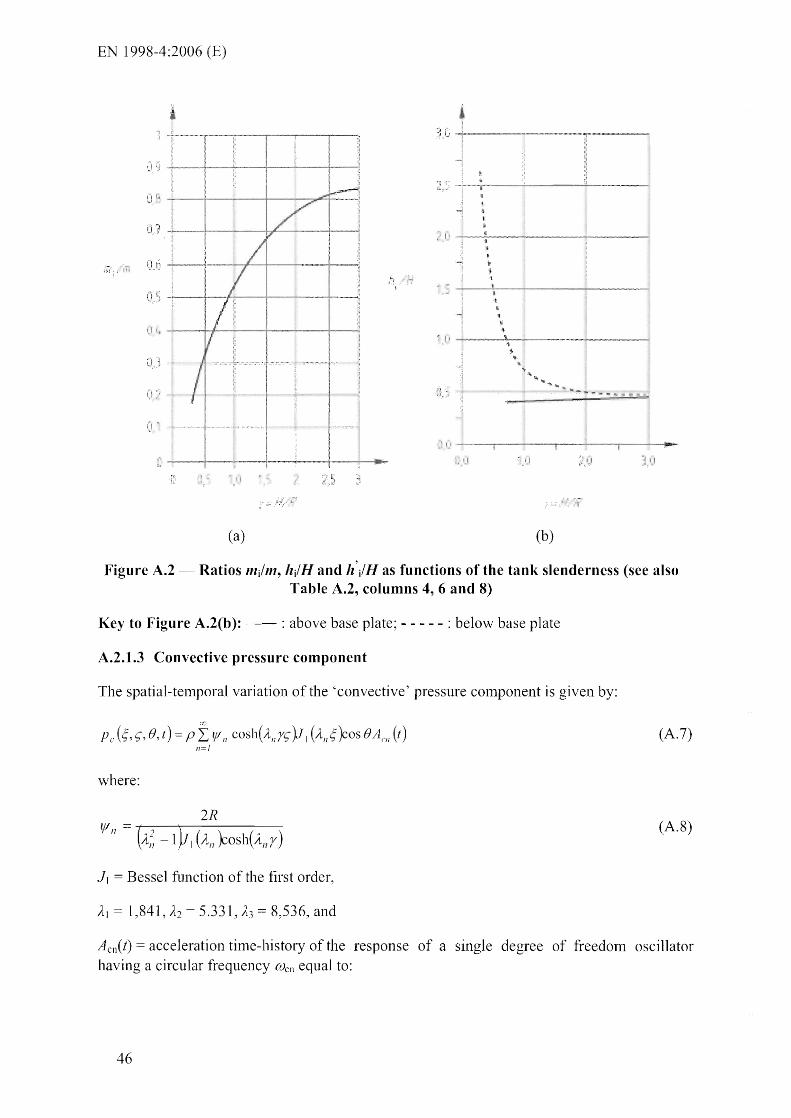
EN 1998-4:2006 (E)
rr( ~, '- '1,11
__ .1---:-_ ____ '" ____ ,_
• I' _ u_-,--__ .......,.-
• , I
(a) (b)
Figure A.2 - Ratios 111/111, h/H and h'/H as functions of the tank slenderness (see also Table A.2, columns 4, 6 and 8)
Key to Figure A.2(b): -- : above base plate; - - - - - : below base plate
A.2.1.3 Convective pressure component
The spatial-temporal variation of the 'convective' pressure component is given by:
Pc (;, c;, B, t) = pI 'I'n COSh(Anrc; )J1 (AIl;)cOS BACIl (t) (A.7)
11= 1
where:
2R (A.8)
J, = Besse] function of the first order,
)L\ = 1,841, )L2 = 5.331, )L3 = 8,536, and
Acn(t) = acceleration time-history of the response of a single degree of freedom oscillator having a circular frequency (Ucn equal to:
46

EN 1998-4:2006 (E)
An ( ) OJen = g-tanh A n r R
(A.9)
and a danlping ratio appropriate for the sloshing of the fluid (see [1] for procedures for the calculation of dalnping).
Only the first oscillating, or sloshing, nlode and frequency of the osci llating liquid (n = 1) needs to be considered in expression (A.7) for design purposes.
The vertical distribution of the sloshing pressures for the first two modes is shown in Figure A.3a), while Figure A.3b) gives the values of the first two frequencies, as functions of the HIR. In squat tanks the sloshing pressures nlaintain relatively high values down to the bottom, while in slender tanks the sloshing effect is lilnited to the vicinity of the surface of the liquid. The sloshing frequencies beconle alnl0st independent of r, for r larger than about 1. For such values of r, We I is approxinlately equal to:
(Uel = 4,2 / JR (R in meters) (A.10)
which, for the usual values of R yields periods of oscillation of the order of few seconds.
j
.' I
:' '.' -I
j
l
. c
2
1 ~,
!
., 1
(a) (b)
Figure A.3 - a) Variation of sloshing pressures along the height in the first two modes and b) values of the first two sloshing frequencies as functions of r
Key: 1: 2nd mode; 2: 1st mode
Pressure resultants:
Convective base shear:
Qc(t)= ~mcI1Acl7 (t) (A. 11 ) 11 =1
where the n-th modal convective mass is:
47

EN 1998-4:2006 (E)
(A.12)
Moment inlmediately below the botton1 plate of the tank:
M'c (t)= I (rl1 o}Acn(t))h'Cil = I QC/1(t)h'C/7 (A.13a) 17=1 17=1
where:
(A.l4a)
The values of mel and me2 and the cOlTesponding values of hel' he2, h'c] and h'c2 are shown in Figure AA as functions of r
,
".
(a) (b)
Figure A.4 - a) First two sloshing nlodal masses and b) corresponding heights he], he2, h'eI and h 'e2 as functions of y(see also Table A.2, columns 5, 7 and 9)
Key to Figure A.4(a): I: I sl mode; 2: 2nd mode.
Key to Figure A.4(b): I A: I st mode, below base plate; 2A: 2nd mode, below base plate; IB: 1 st 1110de, above base plate; 2B: 2nd nlode, above base plate.
Moment in the tank wall immediately above the bottom plate:
Me (t) = f (mel7 ACI1 (t ))hcn = I QCI1 {t )hCil 17=1 17=1
where hen is:
48
(A.13b)

EN 1998-4:2006 (E)
[ l-COSh(AnY)]
hell = H 1 + ----:-( --:-) ysinh An y
(A.14b)
The convective con1pollent of the response ll1ay be obtained fron1 that of oscillators having
n1asses 111en , attached to the rigid tank through springs having stiffnesses: Kn = [Ul~ 171m , (one
oscillator for each n10de considered significant, nort11ally only the first one). The tank is subjected to the ground acceleration tin1e-hisory Ag(t) and the masses respond with accelerations Aen(t). h 'en or hen is the level where the oscillator needs to be applied in order to give the correct value of M'en or Men, respectively.
A.2.1.4 Height of the convective wave
The sloshing wave height is provided n1ainly by the first n10de; the expression for the peak height at the edge is:
(A.IS)
where Se(') is the elastic response spectral acceleration at the 1 st convective mode of the fluid for damping a value appropriate for the sloshing response and g is the acceleration of gravity.
A.2.1.S Effect of the inertia of the walls
For steel tanks, the inertia forces on the shell due to its own mass are sn1all compared with the hydrodynan1ic forces and n1ay be neglected. For concrete tanks, they should not be neglected. Inertia forces are parallel to the horizontal seisll1ic action, inducing a pressure normal to the surface of the shell given by:
where:
Ps = n1ass density of the wall n1aterial
s(~) = wall thickness
(A.16)
The action effects of this pressure component, which follows the variation of wall thickness along the height, should be added to those of the in1pulsive component given by expression (A.l).
The total shear at the base due to the inertia forces of the tank wall and roof n1ay be taken equal to the total mass of the tank walls and root~ tiInes the acceleration of the ground. The contribution to the base overturning lTIOlnent in a sin1ila1' way: it is equal to the wall 111aSS tilTIeS the waH n1idheight (for constant wall thickness), plus the roof mass tilnes its 111ean distance fro1l1 the base, times the acceleration of the ground.
A.2.1.6 Combination of action effects of impulsive and convective pressures
The tin1e-history of the total pressure is the SUlTI of the following two tin1e-histories:
the in1pulsive one being driven by Ag(t) (including the inertia of the wa11s);
the convective one driven by Aci (t) (neglecting higher order con1ponents).
49
EN 1998-4:2006 (E)
In the sanle way that the dynamic response associated with the two pressure C0111pOnents is characterized by different damping ratios, it nlay also be associated with ditferent hysteretic energy dissipation mechanisnls. No energy dissipation can be associated with the convective response of the liquid, whereas sonle hysteretic energy dissipation may accoll1pany the response due to the inlpulsive pressures and the inertia of the tank walls, arising fr01n the tank itself and the way it is supported on (or anchored to) the ground. If energy dissipation is taken into account through modification of the elastic spect111111 by the behaviour factor q, a ditferent value of q should be used in the derivation of action effects of the two c01nponents: q 1,0 for the action effects of the convective pressures and q 1 ,5 (or a higher value) for the action effects of the impulsive pressures and of the inertia of the tank walls.
If, as it is cust0111ary in design practice, the response spectrunl approach is used for the calculation of the lnaxinlunl dynmnic response, the maxima of the two tinle-histories of sei smic action effects given by the response spectrUlll should be suitably conlbined. Due to the generally wide separation between the donlinant frequencies in the ground Inotion and the sloshing frequency, the 'square root of the sum of squares' rule 111ay be unconservative, so that the alternative, upper bound, rule of adding the absolute values of the two nlaxitna nlay be preferable in design. Each of these two nlaxima will be derived for the value of q and of the danlping ratio considered appropriate for the corresponding conlponent.
The value of the monlent and shear force ilnnlediately above the bottom plate of the tank should be used for the calculation of the stresses and stress resultants in the tank walls and at the connection to the base, for the verifications. The value of the In0111ent innnediately below the bottonl plate of the tank should be used for the verification of its support structure, base anchors or foundation.
Due to the long period of the convective conlponellt of the response of the liquid, only the nlonlent below the bottom plate of the tank which is due to this C0111pOnent of the pressure is relevant to the static equilibrium verification of the tank (overturning). Due to their high frequency, the inlpulsive pressures and the inertia of the tank walls nlay be considered not to contribute to the destabilising monlent in the verification of the tank against overturning.
A.2.2 Vertical component of the seismic action
The hydrodynanlic pressure on the walls of a rigid tank due to vertical ground acceleration Av(t) is given by:
(A.I7)
Being axisYlllnletric, this bydrodynanlic pressure does not produce a shear force or 1110nlent resultant at any horizontal level of the tank, or illlinediately above or below the base.
A.2.3 Combination of the effects of the horizontal and the vertical components of the seismic action, including the effects of other actions
The peak conlbined pressure on the tank walls due to horizontal and vertical seismic action 111ay be obtained by applying the rule in 3.2. The c01nbined pressure should be added to the hydrostatic pressure on the wall at the one side of the tank (where the wall accelerates into the liquid) and subtracted as suction at the opposite. Dynanlic earth and ground water pressures should be considered to act against any buried part of the tank on the side of the tank where the SeiSJllic pressure is considered as suction. pressures there should be estimated on the
50

1998-4:2006
basis of the coefficient of earth pressure at rest.
A.3 Deformable vertical circular tanks on-ground, fixed to the foundation
A.3.1 Horizontal components of the seismic action
It is nonnally unconservative to consider the tank as rigid (especially for steel tanks). In flexible tanks the fluid pressure is usually expressed as the sum of three contributions, referred to as: 'rigid inlpulsive', 'sloshing' and 'flexible'. The third satisfies the condition that the radial velocity of the fluid along the wall equals the defor111ation velocity of the tank wall, as well as the conditions of zero vertical velocity at the tank bOttOl11 and zero pressure at the free surface of the fluid. The dynamic coupling between the sloshing and the flexible cOlllponents is very weak, due to the large differences between the frequencies of the sloshing 1110tion and of the deformation of the wall, which allows deternlining the third conlponent independently of the others. The rigid i111pulsive and the sloshing components in A.2 renlain therefore unaffected.
The flexible pressure distribution depends on the lllodes of vibration of the tank-fluid systenl, aillong which only those with one circun1ferential wave, of the following type, are of interest:
~ r;, fJ) = j( r;) cos e (A.18)
In the following, the tenll fundamental or first frequency, or first nlode, is not related to the rea] fundanlental modes of the full tank, but only to eigenmodes of the type of expression (A.I8).
The radial distribution of the f1exible impulsive pressure on the tank botton1 is qualitatively the sanle as for the rigid impulsive pressure. Assunling the modes as known, the flexible pressure distribution on the walls has the foml:
PI' k,r),t) = pH ljICOS e d n cos(VI1 S- )A fiJ (t) 11=0
where:
rl f'( {~s(S-) ~:YJ b' (! r)ld~ .b . S-L p H + L..n=o 11 COS t· 11 '::> J S
ljI = -----=----------=--
1fkt~ S~)l(d+ d" cos(v"sl}s
2 (-1 Y 1[ (Vn / r) VI~ 1 ~ (Vn / r)
d = 2 ilk }:os(v,s)elf" I, (v, / r) n Vn 1; (Vn / r)
(A.19)
(A.20)
(A.21)
(A.22)
Ps is the lllass density of the shell, s( <;) is its thickness and A rn(t) is the response acceleration (relative to its base) of a sinlple oscillator having the period and dalTlping ratio of 1110de 11. The fundanlental nl0de 1) is norn1ally sufficient, so that in expressions (A.19), (A.21), (A.22),
51
EN ] 998-4:2006 (E)
the lTIode index, n, and the sun1111ation over all n10dal contributions are dropped.
In n10st cases of flexible tanks, the pressure Pt{-) in expression (A.19) provides the predoll1inant contribution to the total pressure, due to the fact that, while the rigid in1pulsive tern1 - expression (A.l) - varies with the ground acceleration Ag(t), the flexible tern1 -expression (A.19) - varies with the response acceleration A fn (t) , which, for the usual of periods of the tank-fluid systems, is considerably amplified with respect to Ag(t).
For the detennination of the first mode shape of the tank, the following iterative procedure is suggested in [2], [3]. A trial shape is selected for./C;), in expressions (A.18)-(A.22) (a shape proportional to ; is usually a good approxin1ation, especially for slender tanks). Denoting with .ri(e;) the shape used in the i-th iteration, an 'effective' lTIaSS density of the shell is evaluated as:
(A.23)
where p~. (f') is the value of the pressure evaluated fron1 expression (A.19) at the i-tll step.
The effective 111ass density from expression (A.23) lTIay then be used in a structural analysis of the tank to evaluate the mode shape in the (i+ 1)-th iteration, and so forth until convergence.
The fundan1ental circular frequency of the tank-fluid systenl lTIay be evaluated by means of the following approxinlate expression, derived in [4] for steel tanks:
(Or = (for r;= 1/3)
where E is the elastic n10dulus of the material of the tank wall.
The base shear is:
Qf (t) = In( AI (t)
where:
The nlOlTIent imlnediately above the tank bottom may be calculated as:
where:
hi' H---------------. if) (-lY
52
rLIl=odn -Vn
(A.24)
(A.25)
(A.26)
(A.27)
(A.28)

EN 1998-4:2006 (E)
A.3.2 Combination of the pressure terms due to horizontal components of the seismic action
A.3.2.1 General procedures
The till1e-history of the total pressure is in flexible tanks is the sunl of the time-histories of the rigid ilnpulsive pressure (expression (A.l », of the convective one (expression (A.7», and of the flexible pressure (expression (A.19», each of then1 differently distributed along the height and having a different variation with time. The tin1e-history of the base shear produced by these pressures (expressions (A.3), (A. 1 I ) and (A.25» is:
Q{t) ll1 i Ag (t) imcn (t)+ 111 f Al (I) (A.29)
where Acn(t) is the total or absolute response acceleration of a simple oscillator with circular frequency Olen (expression (A.9» and datnping ratio appropriate for the sloshing response subjected to a base acceleration Ag(t), while A l(t) is the response acceleration (relative to the base) of a sin1ple oscillator of circular frequency {VI' (expression (A.24» and damping appropriate for the tank-fluid systenl, also subjected to Ag(t).
If the individual n1axinla of the terms in expression (A.29) are known, e.g. froll1 a response spectrum of absolute and relative accelerations, the corresponding pressures on the tank needed for a detailed stress analysis nlay be obtained by spreading the resultant of each of the three tenns in expression (A.29) over tank walls and floor according to the relevant distribution of pressures. To expedite the design process, the Inasses mi, men and /11r, the latter based on assunled first mode shapes, have been calculated as functions of the ratio y, and are available in tabular f01111 or in diagra111s (see, for exan1ple, Figures A.2(a), A.4(a), colu111ns 4 and 5 in Table A.2 and [4]). Use of expression (A.29) in combination with response spectra, however, poses the question of the con1bination of the maxilna. Apart fi'on1 the need to derive a relative acceleration response spectruln for A1{t), there is no accurate vvay of con1bining the peak of Ag(t) with that of At(t). As a n1atter of fact, since the input and its response cannot be assulned as independent in the range of relatively high frequencies under consideration, the 'square root of the sum of squares' rule is not sufficiently accurate. On the other hand, addition of the individual n1axil11a could lead to overconservative estilllates.
Given these difficulties, various approximate approaches based on the theory above have been proposed. Three of these, presented in detail in [4], [5], are due to Veletsos and Yang, Haroun and Housner, or Scharf [4].
The Veletsos and Yang approach consists in replacing expression (A.29) with the following:
Q{t) = m i A lei (t) + L m ell (t) . 11=1
(A.30)
i.e., in assulning the entire impulsive mass to respond with the amplified absolute response acceleration of the flexible tank systen1 (AfaCt) Ar(t)+Ag(t» with circular fl'equency (Or
(expression (A.24») and dan1ping appropriate for the tank-fluid systen1. The ll1axinlunl of Ata(t) is obtained directly fron1 the appropriate response spectrun1. The total base shear 111ay be evaluated approximately by the expression:
(A.31)
53

EN 1998-4:2006 (E)
where (£0'/11) is the effective participating Inass of the tank wall in the first nl0de, where 111 is the total nlass of the tank-fluid systenl and the factor £0 may be deternlined fron1 Table A.I:
TabJe A.l Effective participating Inass of tank wall in first mode as fraction of the total, in the Veletsos and Yang procedure
HIR 0,5 1,0 3,0
£0 0,5 0,7 0,9
The Veletsos and Yang procedure provides an upper bound estilnate, acceptable forHIR ratios not lTIuch larger than 1. Above this value, corrections to reduce the conservativeness have been sllggested. In view of the conservative nature of the method, the effects of tank inertia nlay generally be neglected.
In the Haroun and HOllsner approach expression (A.29) is written in a fonn suitable for the use of the response spectrUlTI, as:
Q{t) 0ni - mI )Ag (t)+ I mell (t ) + m I A lcI (t) (A.32)
The Dlasses I11j and 1111' are given in graphs as functions of HI R and siR, together with the heights at which these Inasses should be located to yield the correct value of the base nloment [5]. The effects of the inertia of the tank wall are incorporated in the values of the masses and of their heights.
The 'square root of the sunl of squares' rule is used to combine the l11aximum values of the three conlponents in expression (A.32).
Finally, based on the fact that absolute and relative response accelerations do not differ appreciably in the relevant frequency range, in the Scharf [4] approach expression (A.29) is written as:
(A.33)
The "square root of the sunl of squares" rule is used to c01TIbine the maximunl values of the three conlponents in expression (A.34).
Q= (A.34)
An even nlore silTIplified approach has been proposed in [6] along lines similar to those of Veletsos and Yang, as sunlnlarized below.
A.2.1.4 applies here as well, regarding the different hysteretic energy dissipation mechanisnls (and associated behaviour factor values q) characterising the different pressure cOlnponents.
54

EN 1998-4:2006 (E)
A.3.2.2 Simplified procedure for fixed base cylindrical tanks [6]
A.3.2.2.1 Model
The tank-liquid systenl is modeled by two single-degree-of-freedonl systenls~ one corresponding to the inlpulsive component, 1110ving together with the flexible wall, and the other corresponding to the convective component. The inlpulsive and convective responses are con1bined by taking their nunlerical-sun1.
The natural periods of the itTIpulsive and the convective responses, in seconds, are taken as:
~mr (A.35)
~OIl (A.36)
where:
H = height to the free surface of the liquid;
R tank's radius;
s = equivalent unifonn thickness of the tank wall (weighted average over the wetted height of the tank wall, the weight may be taken proportional to the strain in the wall of the tank, which is maximun1 at the base of the tank);
p= lnass density of liquid; and
E Modulus of elasticity of tank material.
Table A.2 Coefficients Cj and Cc for the natural periods, masses mj and me and heights hi and he from the base of the point of application of the wall pressure resultant, for the
impulsive and convective con1ponents
RIR C, Ce 111/111 mj111 h/H hjR h'/H h'jH ( s/n1112)
0,3 9,28 2,09 0,176 0,824 0,400 0,521 2,640 3,414
0,5 7,74 ],74 0,300 0,700 0,400 0,543 1,460 1,517
0,7 6,97 1,60 0,414 0,586 0,401 0,571 1,009 1,011
1,0 6,36 1,52 0,548 0,452 0,419 0,616 0,72l 0,785
1,5 6,06 1,48 0,686 0,314 0,439 0,690 0,555 0,734
2,0 6,21 1,48 0,763 0,237 0,448 0,751 0,500 0,764
2,5 6,56 1,48 0,810 0,190 0,452 0,794 0,480 0,796
3,0 7,03 1,48 0,842 0,158 0,453 0,825 0,472 0,825
The coefficients Ci and Cc are obtained frOln Table A.2. Coefficient Ci is dinlensionless, while
55
1998-4:2006 (E)
if R is in meters Cc is expressed in s/m l!2.
The inlpu]sive and convective nlasses l11j and l11e are given in Table A.2 as fractions of the total liquid 111ass 111, along with the heights fron1 the base of the point of application of the resultant of the impulsive and convective hydrodynanlic wall pressure, hi and he.
A.3.2.2.2 Seismic response
The total base shear is
where:
I11w mass of the tank wall;
Inr = lnass of tank roof;
(A.37)
Sc(limp) = inlpulsive spectral acceleration, obtained from an elastic response spectrum for a value of damping consistent with the lilnit state considered according to 2.3.3.1;
Sc(Tcoll) = convective spectral acceleration, fronl a 0,5%-damped elastic response spectrum.
The overturning nl0tnent inl1nediately above the base plate is
(A.38)
hw and hr are heights of the centres of gravity of the tank wall and roof, respectively.
The overturning m01nent iml11ediately below the base plate is given by
M' = 011i h'i + I11w h\\, + I11r hr )Sc (~mp)+ me h'c Se (Teoll ) (A.39)
The vertical displacetnent of liquid surface due to sloshing is given by expression (A.15).
A.3.3 Vertical component of the seismic action
In addition to the pressure Pvr( c"t) given by expression (A.l7), due to the tank moving rigidly in the vel1ical direction with acceleration Ait), there is a contribution to the pressure, pvc( c"t), due to the defonnability (radial 'breathing') of the shell [7]. This additional ternl may be calculated as:
where:
fCy)
fCy)
1,078 + 0,274 Iny
1,0
for 0,8:s
for 0,8
4
(AAO)
(AAla)
(AAlb)
AV1{t) is the acceleration response of a sitnple oscillator having a frequency equal to the fundamental frequency of the axisynlnletric vibration of the tank with the fluid.
56

EN 1998-4:2006 (E)
The fundanlental frequency l11ay be estinlated f1'o111 the expression:
.ld (for ~= 1/3) (A.42)
where:
71 = 1[/(2y);
J 0 (.) and II (.) denote the 1110dified Bessel function of order 0 and 1, respectively~
E and v are Young's modulus and Poisson ratio of the tank 111aterial, respectively.
nlaxinlUlTI value of Pvt{t) is obtained fron1 the vertical acceleration response spectrunl for appropriate values of period and dan1ping. If soil flexibility is neglected (see A.7) the
applicable danlping values are those of the n1aterial of the shell. The behaviour factor value, q, adopted for the response due to the impulsive component of the pressure and the tank wall inertia Inay be used for the response to the vertical COlTIpOnent of the seisnlic action. The nlaximum value of the pressure due to the conlbined of Pvl) and Pv!{-) may be obtained by applying the 'square root of the sum of squares' rule to the individualnlaxil11a.
A.3.4 Combination of the effects of the horizontal and vertical components of the seismic action, including the effects of other actions
The pressure on the tank walls should be detennined in accordance with A.2.3.
A.4 Rectangular tanks
A.4.1 Rigid rectangular tanks on-ground, fixed to the foundation
For tanks with walls assunled as rigid, the total pressure is again given by the sun1 of an impulsive and a c011vective contribution:
(A.43)
The impulsive component follows the expression:
(A.44)
where:
L is the half-width of the tank in the direction of the seislnic action;
qoCz) is a function giving the variation of p{) along height as plotted in Figure A.S (P/.) is constant in the direction orthogonal to the seismic action). The trend and the nU111erical values of qo(z) are very close to those of a cylindrical tank with radius R L (see
A.6).
The convective pressure cOll1ponent is given by a sUll1111ation of modal terms (sloshing Inodes). As for cylindrical tanks, the dOlninant contribution is that of the fundanlelltal 1110de:
Pel (Z, t) = qcl (z )pLAI (t) (A.4S)
57
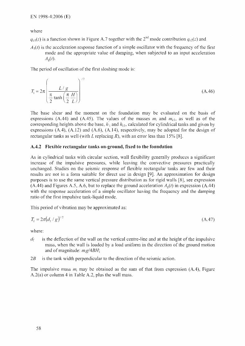
1998-4:2006 (E)
where
qcl(Z) is a function shown in Figure A.7 together with the 2nd nlode contribution qc2(Z) and
A l(t) is the acceleration response function of a sinlple oscillator \\/1th the frequency of the first nl0de and the appropriate value of daITIping~ when subjected to an input acceleration Ag(l).
The period of oscillation of the first sloshing tTIode is:
T. = 2n r L / g ] [ii
I TC tanh (n HJ \ 2 2 L
(AA6)
The base shear and the tuoment on the foundation may be evaluated on the basis of expressions (A.44) and (A.45). The values of the masses l11i and Inc], as well as of the conesponding heights above the base, h'i and hcl~ calculated for cylindrical tanks and given by expressions (AA), (A.12) and (A.6), (A.l4), respectively, nlay be adopted for the design of rectangular tanks as well (with L replacing R), with an enor less than 150/0 [8].
A.4.2 Flexible rectangular tanks on-ground, fixed to the foundation
As in cylindrical tanks with circular section, wall flexibility generally produces a significant increase of the inlpulsive pressures, while leaving the convective pressures practically unchanged. Studies on the seisrnic response of flexible rectangular tanks are few and their results are not in a fornl suitable for direct use in design [9]. An approxinlation for design purposes is to use the sanle vertical pressure distribution as for rigid walls [8J, see expression (A.44) and Figures A.5, A.6, but to replace the ground acceleration Ag(l) in expression (A.44) with the response acceleration of a siluple oscillator having the frequency and the dan1ping ratio of the first ilTIpulsive tank-liquid n10de.
This period of vibration may be approxinlated as:
( )
1 i! 0· = 21l d f / g ,~ (A.47)
where:
dr is the deflection of the wall on the vertical centre-line and at the height of the in1pulsive nlass, when the wall is loaded by a load uniform in the direction of the ground nlotion and of luagnitude: lng/4BH;
28 is the tank width perpendicular to the direction of the seismic action.
The in1pulsive Blass l11i nlay be obtained as the sunl of that froIll expression (A.4), Figure A.2(a) or column 4 in Table A.2, plus the wall mass.
58
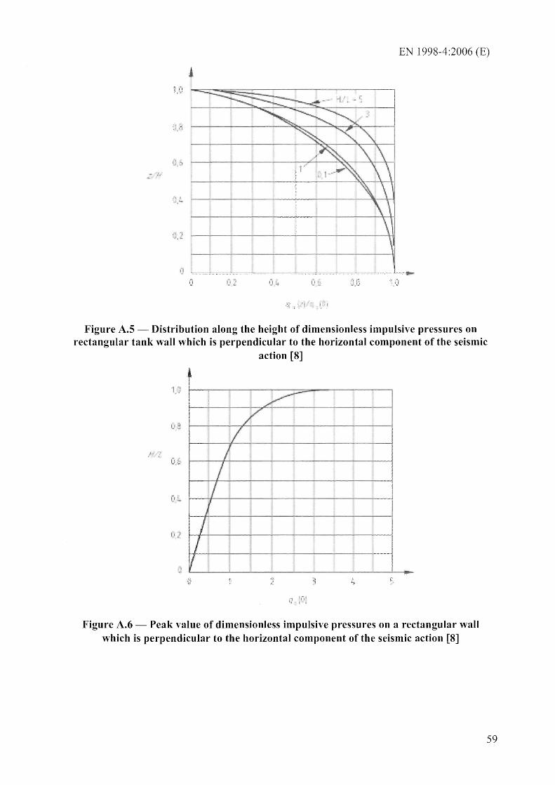
EN 1998-4:2006 (E)
.- ;.
1 '1 .
Figure A.S - Distribution along the height of dimensionless impulsive pressures on rectangular tank wall which is perpendicular to the horizontal component of the seismic
action [8]
.i
Figure A.6 - Peak value of dinlensionless impulsive pressures on a rectangular wall which is perpendicular to the horizontal component of the seisnlic action [8]
59
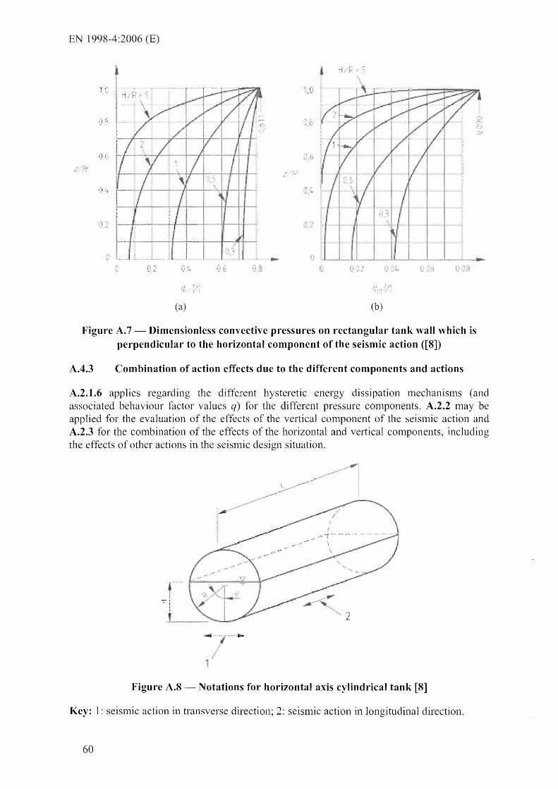
EN 1998-4:2006 (E)
(i' P :,' , ..... " ...... " .... ....... " ......... ........ .. ! ••. •• .. •. . ""',
\ .. , 1_,~~_-r---+-----t-jI'--+---I
,-,',
,-I
(a)
- ~
'_' _J..;
','
,.
,~ :
• I
(b)
Figure A.7 - Dimensionless convective pressures on rectangular tank wall which is perpendicular to the horizontal component of the seismic action ([S])
AA.3 Combination of action effects due to the different components and actions
A.2.1.6 applies regarding the different hysteretic energy dissipation Inechanisnls (and associated behaviour factor values q) for the different pressure conlponents, A.2.2 may be applied for the evaluation of the effects of the vertical cOlnponent of the seislnic action and A.2.3 for the combination of the effects of the horizontal and vertical components, including the effects of other actions in the seis111ic design situation.
--.. -
Figure A.S - Notations for horizontal axis cylindrical tank [S]
Key: 1: seisnlic action in transverse direction; 2: seislnic action in longitudinal direction.
60
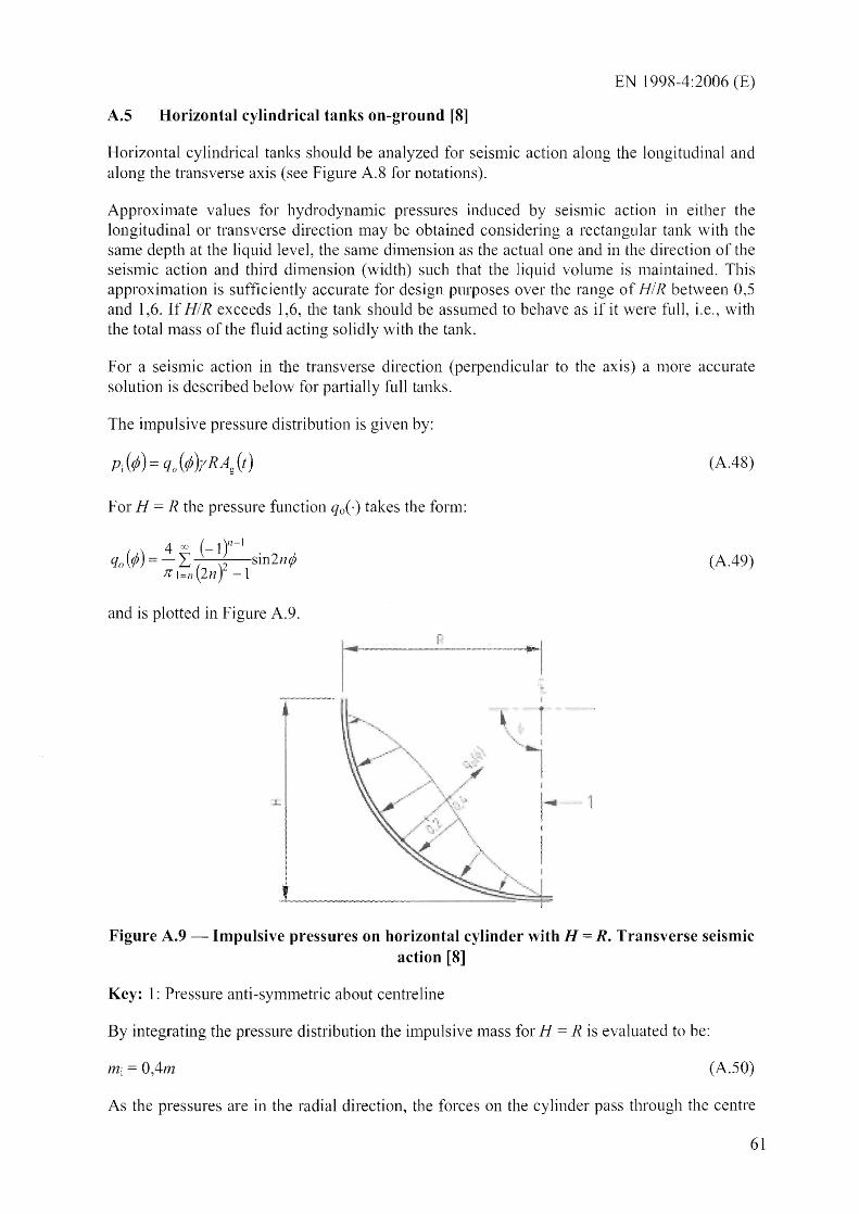
EN 1998-4:2006 (E)
A.S Horizontal cylindrical tanks on-ground [8]
Horizontal cylindrical tanks should be analyzed for seisnlic action along the longitudinal and along the transverse axis (see Figure A.8 for notations).
Approxi111ate values for hydrodynamic pressures induced by seisnlic action in either the longitudinal or transverse direction may be obtained considering a rectangular tank with the same depth at the bquid level, the sanle dinlension as the actual one and in the direction of the seisnlic action and third dimension (width) such that the liquid volume is nlaintained. This approxinlation is sufficiently accurate for design purposes over the range of HI R between 0,5 and 1,6. If HIR exceeds 1,6, the tank should be assumed to behave as if it were full, i.e., with the total111aSS of the fluid acting solidly with the tank.
For a seislnic action in the transverse direction (perpendicular to the axis) a nlore accurate solution is described below for partially full tanks.
The impulsive pressure distribution is given by:
For H = R the pressure function qo(-) takes the fornl:
4 00 (_lY-1 •
qo(¢) = - L: ( )2 . sm2n¢ Jrl=n 2n -1
and is plotted in Figure A.9.
\ . ..... .~
.. ' "', '. .-" ~~ . .,...
.L
I
L _ _ ~ " "~'\
(A.48)
(A.49)
Figure A.9 - Impulsive pressures on horizontal cylinder with H = R. Transverse seismic action [8]
Key: 1: Pressure anti-symnletric about centreline
By integrating the pressure distribution the impUlsive mass for H = R is evaluated to be:
mj = 0,4m (A.50)
As the pressures are in the radial direction, the forces on the cylinder pass through the centre
61

EN 1998-4:2006 (E)
of the circular section. Both the in1pulsive and the convective masses should be assu111ed to be at that point.
Figure A.tO - Dimensionless first convective mode frequency for rigid tanks of various
shapes [8]
Key: 1: Sphere; 2: Horizontal cylinder, transverse seisnlic action; 3: Vertical cylinder, spherical bottOln; 4: Vertical cylinder; 5: Rectangular tank (length: 2L); 5 & 6: Horizontal cylinder, longitudinal seismic action (length: 2L).
Solutions for the convective pressures are not available in a convenient fom1 for design. When the tank is approximately half ful1 (H ~ R), the first sloshing nl0de n1ass n1ay be evaluated as:
mel = 0,6m (A.S1)
Expressions (A.SO), (A.Sl) are considered as reasonable approximations for HIR from 0,8 to 1,2.
The first n10de sloshing frequencies for rigid tanks of various shapes, including horizontal cylinders for seislnic action along and transverse to the axis, are shown in Figure A.l 0.
A.6 Elevated tanks
In the structural model that includes also the supporting structure, the liquid in the tank may be accounted for by considering two nlasses:
62
EN 1998-4:2006 (E)
an impulsive I11aSS mj rigidly connected to the tank walls, located at a height h'j or hi above the tank bottonl (expressions (AA) and (A.6a), (A.6b), respectively);
a mass me 1, connected to the walls through a spring of stiffnessKe I ole lIne I, where (Oe I is given by expression (A.9), located at a height h 'el or hel (expressions (A.12) and (A.14a), (A.14b), respectively).
The response of the systelTI I11ay be evaluated using standard Inodal analysis and response spectra Inethods.
In the simplest case, the global model has only two degrees-of-freedonl, corresponding to the nlasses mj and Incl. A mass L1m equal to the n1ass of the tank and an appropriate portion of the lTIaSS of the support should be added to mi. The 111ass (mi + L1m) should be connected to the ground by a spring representing the stiffness of the support.
Nonnally, the rotational inertia of the mass (mi + ~m), and the corresponding additional degree of freedom, should also be included in the n10deL
Elevated tank in the shape of a truncated inverted cone l11ay be considered in the n10del as an equivalent cylinder of the sanle volume of liquid and a dianleter equal to that of the cone at the level of the liquid.
A.7 Soil-structure interaction effects for tanks on-ground
A. 7.1 General
For tanks founded on relatively deformable soils, the base n10tion can be significantly different fr0111 the free-field n10t10n; in general the translational component is nlodified and there is also a rocking con1ponent. Moreover, for the sanle input Inotion, as the flexibility of the ground increases, the fundan1ental period of the tank-fluid system and the total danlping increase, reducing the peak force response. The increase in the period is nlore pronounced for tall, slender tanks, because the contribution of the rocking component is greater. The reduction of the peak force response, however, is in general for tall tanks, since the danlping associated with rocking is sn1aller than that associated with horizontal translation.
A sinlple procedure, proposed for buildings in [10] and consisting of an increase of the fundamental period and of the datnping of the struchlre, which is considered to rest 011 a rigid soil and subjected to the free-field motion, has been extended to the ilnpuIsive (rigid and flexible) components of the response of tanks in [11], [12], [13]. The convective periods and pressures are assumed not to be affected by soil-structure interaction. A good approximation can be obtained through the use of an equivalent simple oscillator with paralneters adjusted to n1atch frequency and peak response of the actual systen1. The properties of this substitute oscillator are given in [11], [13] in the fonn of graphs, as functions of the ratio HI R, for fixed values of the wall thickness ratio siR, the initial dan1ping, etc.
A.7.2 Simple procedure
A.7.2.1 Introduction
Inore rough procedure [8], sumlnarized below, 111ay be adopted. The procedure operates by changing separately the frequency and the danlping of the in1pulsive rigid and the inlpulsive flexible pressure contributions in A.2 to A.S. In particular, for the rigid in1pulsive pressure
63

EN 1998-4:2006 (E)
c0111ponents, whose tinle-histories are given by the free-field horizontal, Ag(t), and vertical, Ail) accelerations, consideration of soil-structure interaction effects amounts to replacing these time-histories with the response acceleration histories of a single degree of freedom oscillator having natural period and danlping as specified below.
A.7.2.2 j\;lodified natural periods:
'rigid tank' i111pulsive effect, horizontal
'defonnable tank' i111pulsive effect, horizontal
12
'rigid tank', vertical
tldefornlable tank", vertical
where:
mj ,h'j are the 111ass and height of the impulsive component;
1110 is the l11ass of the foundation;
Iq is the stiffness of the "deformable tank" 4;r2 In; ; T
f-
Inlot is the total ll1ass of the filled tank, including the foundation;
k , ! 111, • 4Jf - -, ,wlth 1111 mass of the liquid;
Tl~1
kx, kg, k v are the horizontal, rocking and vertical stiffness of the foundation; and
(A.52)
(A. 53)
(A.54)
(A.55)
ax, af)., a"are frequency-dependent factors converting static stiffnesses into dynamic ones [14 ].
A.7.2.3 Modified damping values:
The general expression for the effective damping ratio of the tank-foundation systenl is:
64
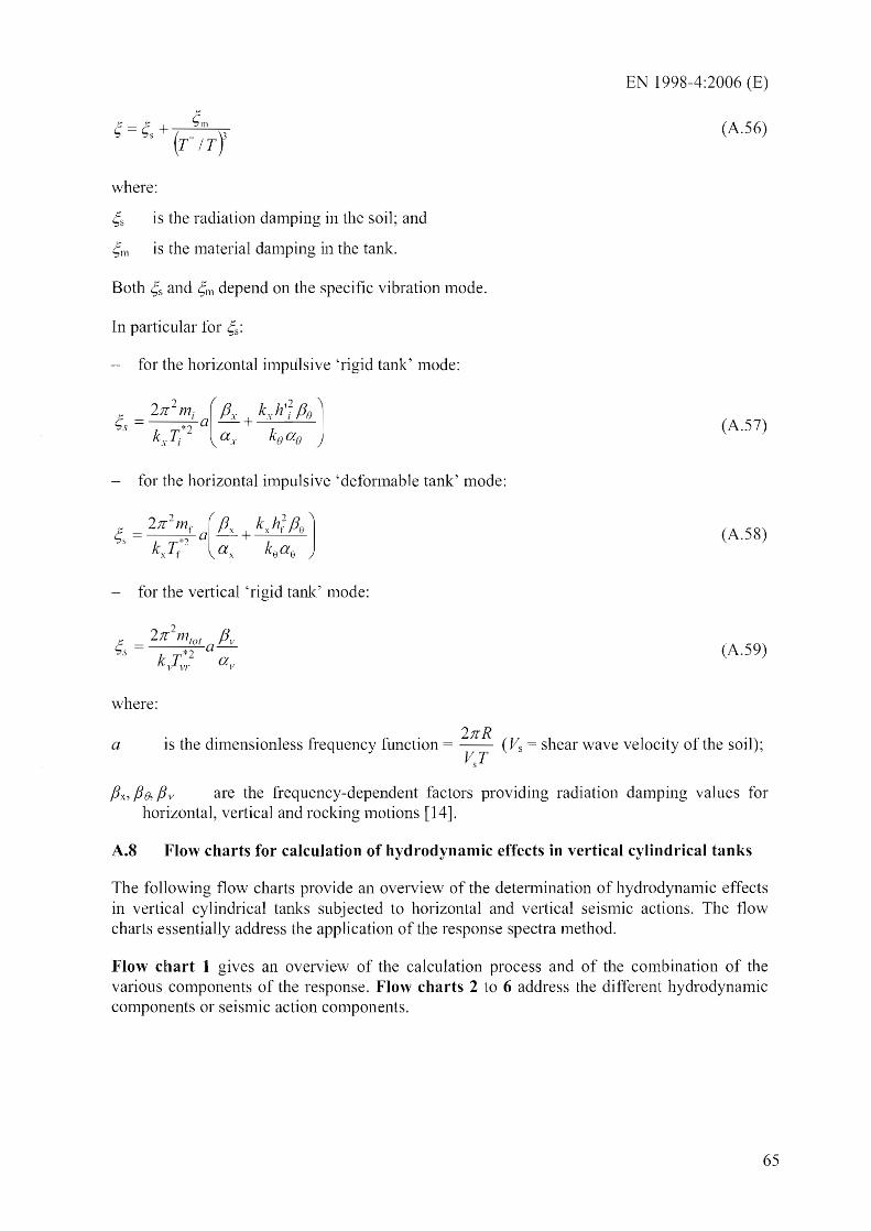
EN 1998-4:2006 (E)
(A.56)
where:
';s 1S the radiation damping in the soil; and
';m is the lTIaterial da111ping in the tank.
Both ';s and ~11 depend on the specific vibration lTIode.
In particular for .
- for the horizontal inlpulsive 'rigid tank' mode:
(A.57)
for the horizontal impulsive 'defonnable tank' mode:
(A.58)
for the vertical 'rigid tank' mode:
(A.59)
where:
. h d' . 1 . 21tR IS t e Imenslon ess frequency functIon = -- (
V.~T a = shear wave velocity of the soil);
fix, fie, fi v are the frequency-dependent factors providing radiation damping vaJues for horizontal, velikal and rocking Inotions [14].
A.8 Flow charts for calculation of hydrodynamic effects in vertical cylindrical tanks
The following flow charts provide an overview of the detennination of hydrodynanlic effects in vertical cylindrical tanks sUbjected to horizontal and vertical seisnlic actions. The flow charts essentially address the application of the response spectra method.
Flow chart 1 gives an overview of the calculation process and of the cOlnbination of the various components of the response. Flow charts 2 to 6 address the different hydrodynamic conlponents or seismic action components.
65
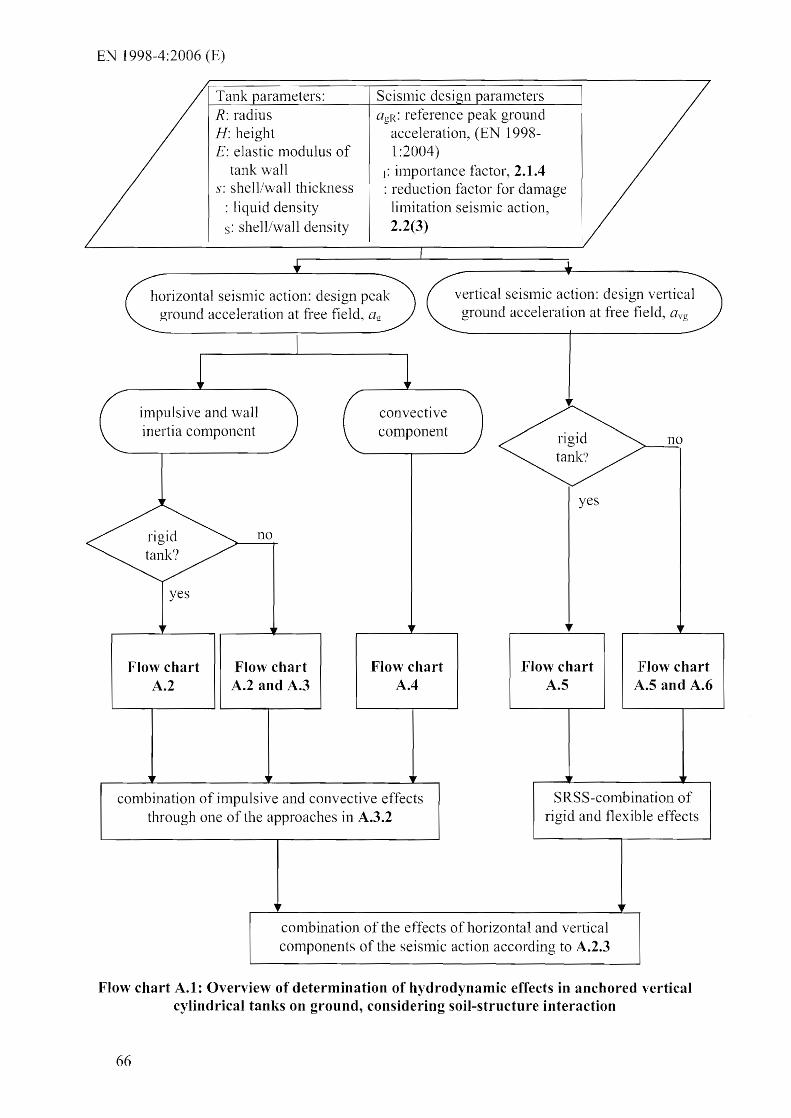
EN 1998-4:2006 (E)
Tank aranleters: R: radius H: height E: elastic modulus of
tank wall s: shell/wall thickness
: liquid density s: shell/wall density
Seisll1ic desi '11 aranleters agR: reference peak ground
acceleration, (EN 1998-1 :2004)
,: inlportance factor, 2.1.4 : reduction factor for danlage lilnitation seismic action, 2.2(3)
horizontal seisnlic action: design peak ground acceleration at free field, af[
vertical seislnic action: design vertical ground acceleration at free field,
impulsive and wal1 inertia conlponent
no
Flow chart A.2
Flow chart A.2 and A.3
convective component
Flow chart A.4
cOtnbination of inlpulsive and convective effects through one of the approaches in A.3.2
yes
Flow chart A.5
no
Flow chart A.5 and A.6
SRSS-combination of rigid and flexible effects
conlbination of the effects of horizontal and vertical components of the seisll1ic action according to A.2.3
Flow chart A.I: Overview of determination of hydrodynamic effects in anchored vertical cylindrical tanks on ground, considering soil-structure interaction
66

EN 1998-4:2006 (E)
rigid wall con1ponent
.. design peak ground acceleration at free field, (EN 1998-1 :2004 and 2.1.4) reduction factor for dan1age lin1itation seismic action (2.2(3) behaviour factor q for ultimate limit state (2.4, 4.4)
Soil-tank interaction
!
~ no
design peak ground acceleration at the free
field, ICigR
yes ..
natural period and danlping fron1
expressions (A.52), (A.56), (A.57)
instead of Cig, response acceleration of SDoF system, aSSl, fro111 response spectrum
of EN 1998-1:2004 for T=Tj* -see exo. (A.52)
wa1l inertia con1ponent
inertia effect of tank
I--
impulsive pressure con1ponent pl , , ,t)
". from expressions (A.l) I ..... ~I----; and (A.2)
~ wallpw( , , ,t) fron1 1 ....... 1-----+
expressions (A.l6)
... ...
.. ..
.. ..
impulsive base shear Qlt) from expressions
(A.3) and (AA) or A.2(a)
in1pulsive overturning lnoment below base plate, M'i( t), from
expressions (A.5a), (A.6a) or Figure A.2
ilnpulsive overtull1ing mon1ent, ~(t), above
base plate fron1 expressions (A.5b) and
(A.6b) or Figure A.2
1
.....
base shear, Qi(t), equal to wall and roof total
~ n1ass, tin1es or aSS!
( A.2.1.~1
overturning n10lnent below base plate,
----flI' M'i(t), equal to wall mass tin1es nlidheight, plus roof mass tin1es
height, times ag or aSSI
(A.2.1.5)
1 overtunling n10n1ent
above base plate: Mlt)=M'lt) (A.2.1.5)
1 I
sum of in1pulsive and inertia con1ponent I
....
Flow chart A.2: Horizontal seismic action, rigid wall impulsive component (see A.2.1, A.7.2)
67

EN I 998-4 :2006 (E)
flexible wall con1ponent
fundall1ental circu lar frequency r from A.3.l,
expression (A.24)
design peak ground acceleration, reduction factor (2.2(3)) dan1ping (2.3.2.1) behaviour factor q (2.4, 4.4)
Soil-tank lnteraction
.. no
yes ..
response spectral acceleration of SDoF oscillator, aI', from response spectrUlTI
of EN 1998-1 :2004 for T corresponding to f - see expo (A.24),
or T=Tr* see expo (A.53)
...
..
impulsive pressure con1ponent, Pf{ , , ,t), froln expressions (A.19)
(A.23)
impulsive base shear, Q1{t), from expressions
(A.25) and (A.26)
impulsive overturning mOlnent M{t) from
expressions (A.27) and (A.28)
n10difications of natural period and
damping, expressions (A.53), (A. 56), (A.58)
Flow chart A.3: Horizontal seismic action, flexible wall impulsive conlponent (see A.3.l, A.7.2)
68

convective component
design peak ground acceleration, ag
reduction factor v (2.2(3) damping ~ (2.3.2.2(1) behaviour factor q 1 (4.4(3)
circular frequency, lUen,
fron1 expression (A.9), for st 1 s10shing mode, J1 1
response spectral acceleration of SOoF system, ac, froln response spectrum of EN 1998-1 :2004 for T corresponding to
Wcn see expo (A.9)
... ..
..
convective pressure conlponent Pe(~, r:; 8, t)
from expressions (A.7) and (A.8), for 1 st mode, n = 1
convective base shear Qc(t) froln expressions (A.Il)
and (A.12), for n 1
convective overturning m01nent below base plate, M' cn(t), frOln expressions
(A.l3a), (A.14a), for n = 1
convective overturning moment above base plate, M' cn(t) , froln expressions
(A.13b), (A.l4b), for n 1
EN 1998-4:2006 (E)
" height of convective
wave dmilx fronl expression (A.I5)
Flow chart A.4: Horizontal seismic action, convective component (see A.2.t)
69

EN 1998-4:2006 (E)
peak vertical ground acceleration at the free
field avg
rigid wall COlTIpOnent
design peak vertical ground acceleration at free field, avg
reduction factor (2.2(3)) behaviour factor q (2.4, 4.4)
no
natural period and dan1ping from expressions
( .54), (A.56), (A.59)
response acceleration of the SDoF systelTI, aSSIv, fro111
vertical response spectrum of EN 1998-1 :2004 for T=Tv/ -
see expo (A.54)
impulsive pressure component Pyre ,t)
from expression ( .17)
Flow chart A.5: Vertical seismic action, rigid wall component (see A.2.2, A.7.2)
70

EN 1998-4:2006 (E)
modified natural period and damping from expressions ( .55),
(A.56), (A.59)
flexible wall component
design peak vertical ground acceleration at free field, aY(T
b
reduction factor (2.2(3)) behaviour factor q (2.4, 4.4)
yes
frequencyf!d frol11 expression
( A2)
response acceleration of the SDoF systel11, aSSlv,
from veliical response spectrUll1 of EN 1998-1 :2004 for T cOlTesponding to.f~!d - see expo
(AA2), or T=Tyd* - see expo (A.55)
inlpulsive pressure conlponent pyr( ,t) fronl
expressions ( AO), (AA1)
Flow chart A.6: Vertical seismic action, flexible wall component (see A.3.3, A. 7 .2)
71

EN 1998-4:2006 (E)
A.9 Unanchored tanks on-ground
A.9.1 General
In tanks on-ground which are not anchored to the foundation, uplift of the tank bottom from the ground will occur due to the seisnlic overturning 1110n1ent. Uplift is lnore pronounced in tanks with open top. Uplift may cause plastic deformations in the tank, especially in its base plate. Tearing and leakage of the liquid, however, should be prevented by design.
tn n10st cases, the effects of uplift and of the acconlpanying rocking n10tion on the magnihtde and the distribution of the pressures are disregarded. For lnost purposes this is conservative, as rocking increases the flexibility of the systenl and shifts the period i11to a range of less dynarnic alnplification of forces.
An approximate and iterative analysis procedure for vertical cylindrical tanks, accounting for uplift and for the dynanlic nature of the problem, is given in [2], [4]. Design charts froll1 this procedure apply to tanks with fixed roof and refer to specific parameters values, such as the ratio of wall thicl<Jless to radi LIS, the soil stiffness, the 'NaIl foundation type, etc.
Once the peak hydrodynanlic pressures are known, whether determined ignoring or considering uplift, calculation of the stresses in the tank is a nlatter of static structural analysis, where the designer has certain freedonl in selecting the level of sophistjcation of the method. For an uplifting tank, an accurate 1110del would necessarily involve a non-linear finite element nlodel of the tank, the soil and their interface. Sin1plified but cOlnprehensive cOlnputer methods have been proposed recently in the literature [15], [16]. Crude n1ethods, not requiring the use of conlputer and proposed for exa111ple in [8], have been proven by experinlents and more refined analyses to be unconservative and inadequate for accounting of all the variables entering the problenl.
The principal effect of uplift is to increase the conlpressive vertical stress in the shell, which is critical for bucIding-related nlodes of failure. At the wall which is on the side opposite to the uplifting one, vertical c01npression is maxinlun1 and hoop compressive stresses are generated in the shell, due to the membrane action of the base plate.
Flexural yielding is accepted to take place in the base plate, and a check of the nlaxinlunl tensile stress is appropriate.
A.9.2 Compressive vertical membrane forces and stress in the wall due to uplift
The increase of the verticallnelnbrane force due to uplift (Nu) with respect to that stress in the anchored case (Na) may, for the usual fixed-roof cylindrical steel tanks on-ground in the petrochenlical industry, be estimated fronl Figure A.ll [4], as a function of the nondinlensional overturning mon1ent,MIWH (W = total weight of the liquid). For slender tanks the increase is very significant. For fixed roofs, the values in Figure A.iI are on the safe side, since they have been calculated (using static finite element analysis) assuming that the underlying soil to be quite stiff (Winkler springs with a sub grade reaction nlodulus k 4000 MN/n13
) which is unfavourable for vertical n1elnbrane forces.
72
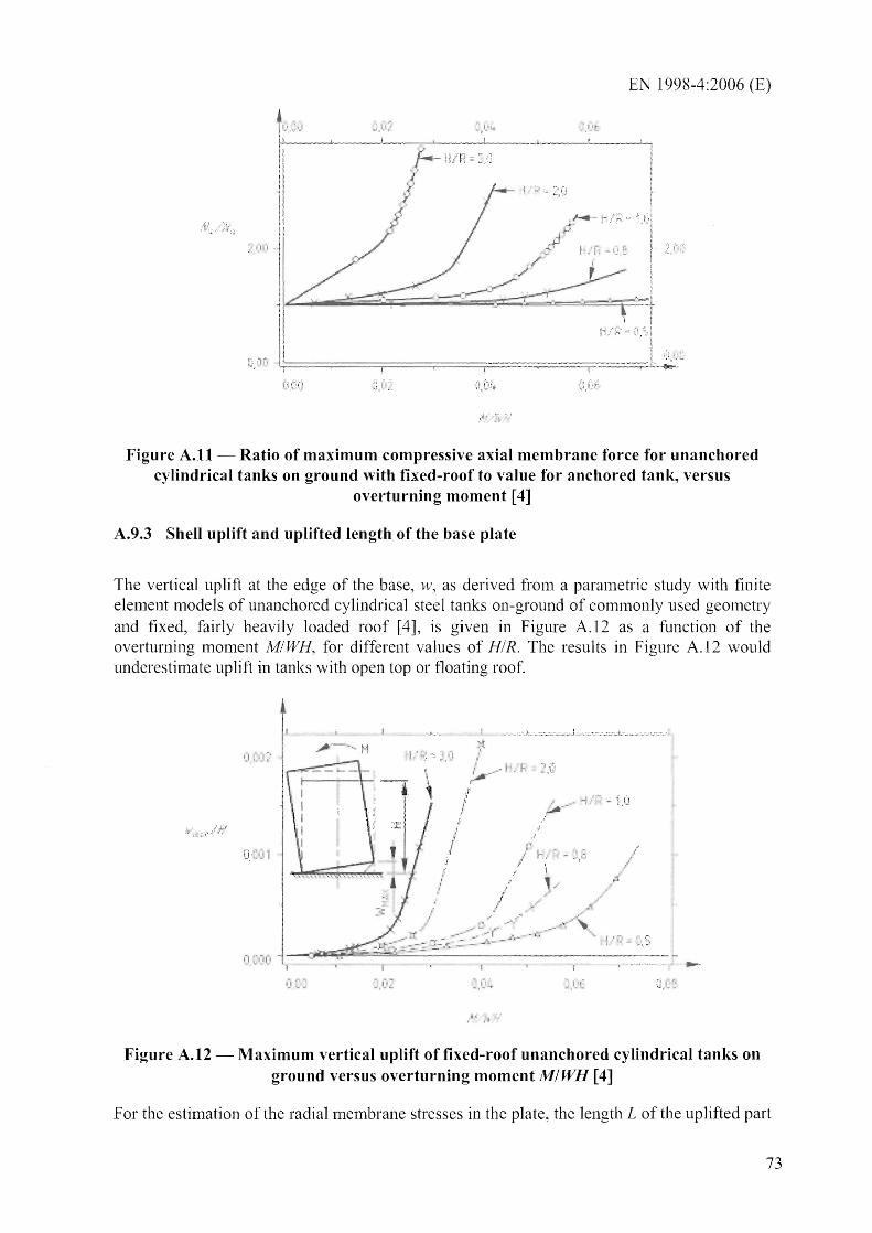
EN 1998-4:2006 (E)
;.i i "
Figure A.II - Ratio of maximum compressive axial membrane force for unanchored cylindrical tanks on ground with fixed-roof to value for anchored tank, versus
overturning moment [4]
A.9.3 Shell uplift and uplifted length of the base plate
The vertical uplift at the edge of the base, w, as derived froln a parmnetric study with finite element 1110dels of unanchored cylindrical steel tanks on-ground of comlTIonly used geOlnetry and fixed, fairly heavily loaded roof [4], is given in Figure A.12 as a function of the overturning moment MIWH, for different values of HIR. The results in Figure A.12 would underestimate uplift in tanks with open top or floating roof.
o . ~·.! 1
,t
: . I .. "' .:~"-..
, .
-' ..... -;.,. .-t
:''' , ! .;:. - ',,,5
~.
Figure A.12 - Maximum vertical uplift of fixed-roof unanchored cylindrical tanks on ground versus overturning moment MIWH [4]
For the estimation of the radial men1brane stresses in the plate, the length L of the uplifted part
73

EN 1998-4:2006 (E)
of the tank bottonl is necessary. Results fron1 [4] for fixed-roof tanks are shown in Figure A.13. Once uplift occurs, the dependence of L on the vertical uplift w is almost linear.
/ -\ --"
(a) (b)
Figure A.I3 - Length of uplifted part of the base in fixed-roof unanchored cylindrical tanks on ground as a function of the vertical uplift at the edge [4]
A.9.4 Radial membrane stresses in the base plate [17], [18]
An estimate of the n1enlbrane stress a;'b in the base plate due to uplift is given in [17]:
1(2 E . )113 () rb = - - -.. --, .sp 2 R 2 (1 - f1 r
s 3 1- \/-
where:
s is the thickness of the base plate;
p is the pressure on the base;
Jl = 1- L/(2R), with L = uplifted part of the base.
(A.60)
When significant uplift takes place in large diameter tanks, the state of stresses in the uplifted part of the base plate at the ultimate limit state is dominated by plate bending (including the effect of the pressure acting on the tank base), not by nlembrane stresses. In such cases the finite elen1ent Inethod should be used for the calculation of the state of stresses.
A.9.S Plastic rotation of the base plate
It is rec01nmended to design the bottom annular ring with a thickness less than the wall thickness, so as to avoid flexural yielding at the base of the wall.
The rotation of the plastic hinge in the tank base should be compatible with the available flexural defonnation capacity. For a Inaxinlum allowable steel strain of 0,05 and a postulated length of the plastic hinge equal to 2s, the Inaxinlum allowable rotation is 0,20 rads. Fronl Figure A.14 the rotation associated to an uplift at the edge wand a base separation of Lis:
74
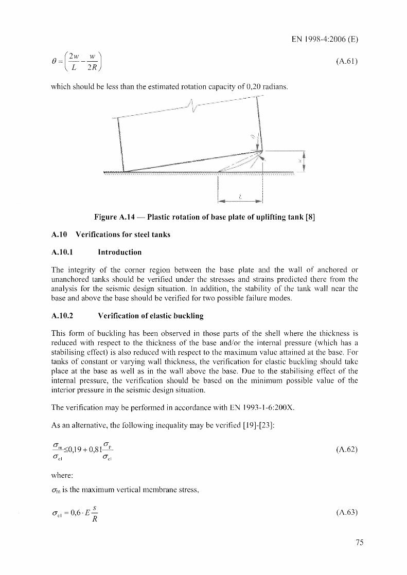
EN 1998-4:2006 (E)
(A.61)
which should be less than the estinlated rotation capacity of 0,20 radians.
Figure A.14 - Plastic rotation of base plate of uplifting tank [8]
A.tO Verifications for steel tanks
A.IO.I Introduction
The integrity of the corner region between the base plate and the wall of anchored or unanchored tanks should be verified under the stresses and strains predicted there from the analysis for the seislnic design situation. In addition, the stability of the tank wall near the base and above the base should be verified for two possible failure nl0des .
A.IO.2 Verification of elastic buckling
This form of buckling has been observed in those parts of the shell where the thickness is reduced with respect to the thickness of the base and/or the internal pressure (which has a stabilising effect) is also reduced with respect to the lnaximunl value attained at the base. For tanks of constant or varying wall thickness, the verification for elastic buckling should take place at the base as well as in the wall above the base. Due to the stabilising effect of the intenlal pressure, the verification should be based on the InininlU1n possible value of the interior pressure in the seismic design situation.
The verification may be perfonned in accordance with EN 1993-1-6:200X.
As an alternative, the following inequality may be verified [19]-[23]:
O"m sO,19 + 0,81 O"p
O"cl O"ci
where:
OJ)) is the maximum vertical merrlbrane stress,
S O"ci =0,6·E
R
(A.62)
(A.63)
75

EN 1998-4:2006 (E)
is the ideal critical buckling stress for cylinders loaded in axial compression, and
(A.64)
where:
- pR p=--<5 (A.65)
SO"c1
with p denoting the minimum possible interior pressure in the seismic design situation,
A.tO.3
(A.66a)
0"0 = 0" O"c1 if: (A.66b)
with: a = 1-1,24(~J [1 + 2 : 112 1 1,24(~J -
(A.67)
and b/s denoting the ratio of maximunl imperfection amplitude to wall thickness, which nlay be taken as [8]:
(~J = 0,06 fR s a~--;
where:
a = 1 for nOlmal construction
a = 1,5 for quality construction
a = 2,5 for very high quality construction
Elastic-plastic collapse
(A.68)
This form of buc1ding ('elephant's foot') nm"mal1y occurs close to the base of the tank, due to a combination of vertical compressive stresses and tensile hoop stresses inducing an inelastic biaxial state of stress. In tanks with variable wall thiclaless, verification for this nlode of buckling should not be limited to the section close to the base of the tank, but should extend to the bottmn section of all parts of the wall which have constant thickness.
The enlpirical equation developed in [24]-[25] to check this fonn of instability is:
76

EN 1998-4:2006 (E)
Il2+r1.15 , (A.69)
where:
R Is r=--'
400 '
,h is the yield strength of the tank wall material in lV1Pa; and
p is the maximum possible interior pressure in the seisnlic design situation, in MPa.
References
[1] Habenberger, 1. and Schwarz, .I., Danlping effects of the fluid in cylindrical liquid storage tanks, Earthquake Engineering and Structural Dynamics, 2005, 33.
[2] Fischer, F.D.; Ranlmerstorfer, F.G. and Scharf, K., Earthquake Resistant Design ql Anchored and Unanchored Liquid Storage Tanks under Three-dimensional Earthquake Excitation. Structural Dynamics Recent Advances, Schueller, G.L. (Ed.). Springer Verlag. 1991
[3] Ratnmesstorfer, F.G., Scharf, K., Fischer, F.D. and Seeber, R., Collapse of Earthquake Excited Tanks, Res Mechanica. 1988,25,129-143.
[4] Scharf, K., Beitrage zur Erfassung des Verhaltens von erdbebenerregten, oberirdischen Tankbauwerken, Fortschritt-Berichte VDI, Reihe 4. Bauingenieurwesen, Nr. 97, VDI Verlag, DUsseldorf, 1990.
[5] Guidelines for the Seisnlic Design of Oil and Gas Pipeline SystelTIs. Technical Council on Lifeline Earthquake Engineering. 1987.
[6] Malhotra, P.K., Seismic Response of Soil-Supported Unanchored Liquid-Storage Tanks, ASCE, Journal of Structural Engineering, 1997, 123,440-449.
[7] Fischer, F.D., Seeber, R., Dynamic Response ofVeliically Excited Liquid Storage Tanks considering Liquid-Soil-Interaction. Earthquake Engineering and Structural Dynanlics. 1988, 16, 329-342.
[8] Priestley, MJ.N. (Ed.), Davidson, BJ., Honey, G.D., Hopkins, D.C., Martin, R.J., Ratnsay, G., Vessey, J.V. and Wood, J.H., Seismic Design of Storage Tanks -Recommendations of a Study Group of the New Zealand National Society for Eatihquake Engineering. Decenlber 1986.
[9] Kiln, lK., Koh, H.M. and Kwack, LJ., Dynamic Response of Rectangular Flexible Fluid Containers. ASCE, Journal ~lEngineering Mechanics, 1996, 122(9), 807-817.
[10] Veletsos, B.S., Dynamics of Structure - Foundation Systenls - Structural and Geotechnical Mechanics. Ed. WJ. Hall, Prentice Hall, Inc., Englewood Cliffs, New Jersey, 1977, 333-361.

EN 1998-4:2006 (E)
[11] Veletsos, A.S. and Yu Tang, Soil-Structure Interaction Effects for Laterally Excited Liquid Storage Tanks. Earthquake Engineering and Structural Dynamics, 1990, 19, 473-496.
[l2] Veletsos A.S., Yu Tang, and H.T. Tang, Dynanlic Response of Flexibly Supported Liquid Storage Tanks. ASCEJ Journal of Structural Engineering, 1992,118(1),264-283.
[13] Habenberger, l and Schwarz, l, Seismic Response of Flexibly Supported Anchored Liquid Storage Tanks, Proc. 13th EuropeLlI1 COl?ference on Earthquake Engineering, London, 2002.
[14] Gazetas, G., Analysis of Machine Foundation Vibrations: State-of-the-Art. Soil Dynamics and Earthquake Engineering. 1983, 2(1), 2-43.
[15] Malhotra, P.K., Practical Nonlinear SeiS1111C Analysis of Tanks. Earthquake Spectra. 2000, 16(2), 473-492.
[16] Peek, R. and Jenning, P.C., Simplified Analysis of Unanchored Tanks. Earthquake Engineering and Structural Dynarnics, 1988, 16, 1073-1085.
[17] Canlbra FJ., Earthquake Response Considerations of Broad Liquid Storage Tanks, Report EERC 82/25, 1982
[18] Fischer, F.D.; Ramlnerstorfer, F.G. and Schreiner, The Extensible Uplifted Strip. Acta Mechanica. 1989,80,227-257.
[19] Rotter, J.M., Buckling of Ground-Supported Cylindrical Steel under Vertical Conlpressive Wall Loads, Proc .. Metal Structures C0I1/erence, Institution of Engineers of Australia, Melbou111e, 1985, 11 127.
[20] Rotter, 1.M., Buckling of cylindrical shells under axial cOlnpression, in Buckling of Thin Metal Shells, eds lG. Teng & lM. Rotter, Spon, London, 2004, 42-87.
[21] Rotter, lM. and Hull, T.S., WaH Loads in Squat Steel Silos during Earthquakes, Engineering Structures, 1989,11(3),139-147.
[22] Gaylord, E.H. and Gaylord, C.N., Design of Steel Bins for Storage q/ Bulk Solids, 1984, Prentice Hall.
[23] Trahair, N.S., Abel, Ansourian, P., Irvine, H.M. and Rotter, lM. Structural Design of Steel Bins for Bulk Solids, Australian Institute of Steel Construction, 1983, Sydney.
[24] Rotter, lM., Local Inelastic Collapse of Pressurised Thin Cylindrical Steel Shells under Axial COlllpression, ASCE, Journal of Structural Engineering, 1990, 116(7), 1955-1970.
[25] Rotter, lM., Seide, P., On the Design of Unstiffened Shells Subjected to an Axial Load and Internal Pressure. Proc qf ECCS Colloquium on Stability of Plate and Shell Structures. Ghent University, 1987, 539-548.
[25] Fischer, F.D. and Ramnlerstorfer, F.G., Coupling of Sloshing vvith the Wall Motion in Seil11ically Excited Tanks. IntI Journal f!/ Pressure Vessel and Piping, 1999, 76, 693-709.
78

ANNEX B (INFORl\'lA TIVE)
BURIED PIPELINES
B.l General design considerations
1998-4:2006 (E)
(1) As a rule, pipelines should be laid on soils which are checked to renlain stable under the design seismic action. When the condition above cannot be satisfied, the nature and the extent of the adverse phenoll1ena should be explicitly assessed, and appropriate design counter measures applied.
(2) T\vo extreme cases: Soil liquefaction and fault movenlents are worth being nlentioned, since they require in general design solutions specific to each particular case.
(3) Soil liquefaction, whenever it did occur, has been a nlajor contributor to pipelines distress in past earthquakes.
(4) Depending on the circumstances, the solution nlay require either increasing the burial depth, possibly also encasing the pipes in larger stiff conduits, or in placing the pipeline above-ground, supp011ing it at rather large distances on well founded piers. In the latter case flexible joints should also be considered to allow for relative displacell1ents between supports.
(5) Design for fault movements requires estinlating, sometinles postulating, a l1U111ber of parameters including: location, size of the area affected, type and nleasure of the fault displacement. Given these paranleters, the simplest way of modelling the phenomenon is to consider a rigid displacement between the soillnasses interfacing at the fault.
(6) The general criterion for lllininlizing the effect of an inlposed displacenlent is that of introducing the maximunl flexibility into the system which is subjected to it.
(7) In the case under consideration this can be done:
by decreasing the burial depth so as to reduce the soil restraint;
- by providing a large ditch for the pipes, to be filled with soft nlaterial;
by putting the pipeline above ground, and introducing flexible and extensible p1pmg elenlents.
B.2 Seismic actions on buried pipelines
(1) The ground motion propagating beneath the soil surface is nlade up of a nlixture of body (compression, shear) and surface (Rayleigh, Love, etc) waves: the actual COll1position depending 1nost significantly on the focal depth and on the distance between the focus and the site.
(2) The various types of waves have different propagation velocities, and ditTerent motions of the particles (i.e. parallel to the propagation of the wave, orthogonal to it, elliptical, etc.). Although geophysical-seismological studies can provide SOl1le insight, they are generally unable to predict the actual \vave patten1, so that conservative assun1ptions have to be lllade.
79

EN 1998-4:2006 (E)
(3) One often nlade assunlption is to consider in turn the wave pattern to consist entirely of a single type of wave, whatever is l1lore unfavourable for a particular effect on the pipeline.
(4) The wave trains can in this case be easily constructed on the basis of the fi-equency content underlying the elastic response spectrUll1 appropriate for the site, by assigning to each frequency c01nponent an estimated value of the propagation velocity.
(5) Theoretical arguments and a nunlber of numerical simulations indicate that the inertia forces arising fron1 the interaction between pipe and soil are 111uch sma]]er than the forces induced by the soil defornlatioll. This fact allows the soil-pipeline interaction problem to be reduced to a static one, i.e., one where the pipeline is deformed by the passage of a displacement wave, without consideration of dynan1ic effects.
(6) The forces on the pipeline can therefore be obtained by a titne-history analysis, where tinle is a paranleter whose function is to displace the wave along or across, the structure, which is connected to the soil through radial and longitudinal springs.
(7) A 111uch sinlpler n1ethod is often used, whose accuracy has been proved to be cOl11parable with the nlore rigorous approach described above, and which yields in any case an upper bound estinlate of the strains in the pipeline, since it assumes it to be flexible enough to follow without sJippage nor interaction the deformation of the soil.
(8) According to this l11ethod [1] the soil Illation is represented by a single sinusoidal wave:
u(x, t) d sin w(t x) c
where d is the total displaceillent an1plitude, and c is the apparent wave speed.
(B.1)
(9) The particle nl0tion is assul11ed in tunl to be along the direction of propagation (compression waves), and nornlal to it (shear waves) and, for sinlplicity and in order to take the worst case, the pipeline axis and the direction of propagation coincide.
(10) The longitudinal particle lTIOVenlent produces strains in the soil and in the pipeline given by the expression:
au wd x (; = - = cosw(t-) (B.2)
c c
whose lTIaxinlUI11 value is:
v (8.3) Gmax =
C
where:
v ox! the peak soil velocity
(II) The transverse particle lnovelllent produces a curvature X in the soil and in the pipe given by the expression:
80
EN 1998-4:2006 (E)
x 2
W d. ( X) 2 SInW t
c c (BA)
whose maXinlUlTI value is:
a (B.5) X max =
c2
where:
a = ei d the peak soi 1 acceleration.
(12) For the condition of perfect bond between pipe and soil to be satisfied, the availab1e friction force per unit length should equilibrate the variation of the longitudinal force leading to:
sE a (B.6)
where:
E Modulus of Elasticity of the pipe;
s thickness of the pipe; and
rav average shear stress between pipe and soil which depends on the friction coefficient between soi 1 and pipe, and on the burial depth.
Bibliography
[1] Newmark, N. M., Problems in Wave Propagation in Soil and Rock, Proc. 1ntnl. Symp. on Wave Propagation and Dynamic Properties of Earth Materials, Univ. of New Mexico, Albuquerque, New Mexico, 1967,7-26
81