EN 1993-1-7: Eurocode 3: Design of steel structures - Part ... · PDF fileEurocode 3 -Design...
39
EN 1993-1-7 (2007) (English): Eurocode 3: Design of steel structures - Part 1-7: Strength and stability of planar plated structures subject to out of plane loading [Authority: The European Union Per Regulation 305/2011, Directive 98/34/EC, Directive 2004/18/EC]
Transcript of EN 1993-1-7: Eurocode 3: Design of steel structures - Part ... · PDF fileEurocode 3 -Design...

The European Union
In order to promote public education and public safety, equal justice for all, a better informed citizenry, the rule of law, world trade and world peace, this legal document is hereby made available on a noncommercial basis, as it is the right of all humans to know and speak the laws that govern them.
≠ EDICT OF GOVERNMENT ±
EN 1993-1-7 (2007) (English): Eurocode 3: Design of steelstructures - Part 1-7: Strength and stability of planarplated structures subject to out of plane loading[Authority: The European Union Per Regulation 305/2011,Directive 98/34/EC, Directive 2004/18/EC]


EUROPEAN STANDARD
NORME EUROPEENNE
EUROpAISCHE NORM
EN 1993-1-7
April 2007
ICS 91.010.30: 91.080.10 'T'\{~"·c{,.(I,,c ENV 1993-1-7: 1999 nf'r\lT"'I"~ll corri ge nd II III A pri I 2009
English Version
Eurocode 3 - Design of steel structures - Part 1-7: Plated structures subject to out of plane loading
Eurocode 3 - Calcul des structures en acier - Partie 1-7: Resistance et stabilite des structures en plaques planes
chargees hors de leur plan
Eurocode 3 - Bemessung und Konstruktion von Stahlbauten - TeiI1-7: Plattenf6rmige Bauteile mit
Querbelastung
This European Standard was approved by CEN on 12 June 2006.
CEN members are bound to comply with the CEN/CENELEC Internal Regulations which stipulate the conditions for giving this European Standard the status of a national standard without any alteration. Up-to-date lists and bibliographical references concerning such national standards may be obtained on application to the CEN Management Centre or to any CEN member.
This European Standard exists in three official versions French, German). A version in any other language made by translation under the responsibility of a CEN member into its own language and notified to the CEN Management Centre has the same status as the official versions.
CEN members are the national standards bodies of Austria, Belgium, Bulgaria, Cyprus, Czech Republic, Denmark, Estonia, Finland, France, Germany, Greece, Hungary, Iceland, Ireland, Italy, Latvia, Lithuania, Luxembourg, Malta, Netherlands, Norway, Poland, Portugal, Romania, Slovakia, Slovenia, Spain, Sweden, Switzerland and United Kingdom.
EUROPEAN CO:\1MITTEE FOR STANDARDIZATION
COMITE EUROPEEN DE NORMALISATION
EUROPAISCH KOMITEE FUR NORMUNG
Management Centre: rue de Stassart, 36 B-1 050 Brussels
© 2007 CEN All rights of exploitation in any form and by any means reserved worldwide for CEN national Members.
Ref. No. EN 1993-1-7:2007:

BS EN 1993-1-7:2007 EN 1993-1-7: 2007 (E)
Content Page
Fore\","ord ..............................................................................•............................................................................ 3
1 Gelleral ....................................................................................................................................................... 4 1. J Scope ................................................................................................................................................ 4 1.2 Norn1ative references ........................................................................................................................ 4 1.3 Tern1s and definitions ....................................................................................................................... 5 ].4 SYlnbo]s ............................................................................................................................................ 6
2 Basis of design ........................................................................................................................................... 9 2.1 Requirelnents .................................................................................................................................... 9 2.2 Principles of limit state design .......................................................................................................... 9 2.3 Actions .............................................................................................................................................. 9 2.4 Design assisted by testing ............................................................................................................... 10
3 J\tlaterial properties ................................................................................................................................. 10
4 Durability ................................................................................................................................................. 10
5 Structural analysis .................................................................................................................................. 10 5.1 General ........................................................................................................................................... 10 5.2 Stress resultants in the plate ............................................................................................................ 10
6 U"timate limit state .................................................................................................................................. 15 6. 1 General ........................................................................................................................................... 15 6.2 Plastic lin1it ..................................................................................................................................... 15 6.3 Cyclic plasticity .............................................................................................................................. 16 6.4 Buckling resistance ......................................................................................................................... 17
7 Fatigue ..................................................................................................................................................... 18
8 Serviceability lilllit state ......................................................................................................................... 18 8.1 (Jeneral ........................................................................................................................................... 18 8.2 Gut of plane deflection ................................................................................................................... 18 8.3 Excessi ve vibrations ....................................................................................................................... 18
Annex A [informative] - Types of analysis for the design of plated structures ........................................ 19 A.I General ........................................................................................................................................... 19 A.2 Linear elastic plate analysis (LA) ................................................................................................... 19 A.3 Geometrically nonlinear analysis (GNA) ....................................................................................... 19 AA Materially nonlinear analysis (MNA) ............................................................................................. 20 A.5 Geometrically and material1y nonlinear analysis (GMNA) ............................................................ 20 A.6 Geometrically nonlinear analysis elastic with imperfections included (GNIA) ............................. 20 A.7 Geometrically and materially nonlinear analysis with imperfections included (GMNIA) ............. 20
Annex B [informative] Internal stresses of unstiffened rectangular plates from small deflectioll theOr)l ........................•..........................••..••............•.••••.......•••...••••.•......•..•...•...••....•••....•.......•..•.•••. 21
B.l General ........................................................................................................................................... 21 B.2 Syn1bols .......................................................................................................................................... 21 B.3 Uniformly distributed loading ........................................................................................................ 21 B.4 Central patch loading ...................................................................................................................... 24
Annex C [informative] - Internal stresses of unstiffened rectangular plates from large deflection theory ............................................................................................................................................. 26
C.l General ........................................................................................................................................... 26 C.2 Sylnbols .......................................................................................................................................... 26 C.3 Uniformly distributed loading on the total surface of the place ..................................................... 26 C.4 Central patch loading ...................................................................................................................... 32
2

Foreword
Foreword
BS EN 1993-1-7:2007 EN 1993-1-7: 2007 (E)
This European Standard EN 1993-1 Eurocode 3: Design of steel structures: Part 1-7 Plated structures subject to out of plane loading, has been prepared by Technical Committee CENITC2S0 «Structural Eurocodes », the Secretariat of which is held by BSI. CEN/TC250 is responsible for all Structural Eurocodes.
This European Standard shall be given the status of a National Standard, either by publication of an identical
text or by endorsement, at the latest by October 2007, and conflicting National Standards shall be withdrawn at latest by March 2010.
This Eurocode supersedes ENV 1993-1-7.
According to the CEN-CENELEC Internal Regulations, the National Standard Organizations of the
following countries are bound to implement this European Standard: Austria, Belgium, Bulgaria Cyprus, Czech Republic, Denmark, Estonia, Finland, Germany, Greece, Hungary, Iceland, Ireland, Italy, Latvia, Lithuania, Luxembourg, Malta, Netherlands, Norway, Poland, Portugal, Romania, Slovakia, Slovenia, Spain, Sweden, Switzerland and United Kingdom.
National annex for EN 1993-1-7
This standard gives alternative procedures, values and recommendations with notes indicating where national choices may have to be made. The National Standard implementing EN 1993-1-7 should have a National Annex containing a]] Nationally Determined Parameters to be used for the design of steel structures to be constructed in the relevant country.
National choice is allowed in EN 1993-1-7 through:
6.3.2(4)
3

BS EN 1993-1-7:2007 EN 1993-1-7: 2007 (E)
1 General
1.1 Scope
(l)P EN 1993-1-7 provides basic design rules for the structural design of unstiffened and stiffened plates ,..vhich form pal1 of plated structures such as silos, tanks or containers, that are loaded by out of plane actions. It is intended to he used in conjunction with EN 1993-1-1 and the relevant application standards.
(2) This document defines the design values of the resistances: the partial factor for resistances may be taken from National Annexes of the relevant application standards. Recommended values are given in the relevant application standards.
(3) This Standard is concerned with the requirements for design against the ultimate limit state of:
plastic co]]apse;
cyclic plasticity;
buckling;
fatigue.
(4) Overall equilibrium of the structure (sliding, uplifting, overturning) is not included in this Standard, but is treated in EN 1993-1-1. Special considerations for specific applications may be found in the relevant applications paI1s of EN 1993.
(5) The rules in this Standard refer to plate segments in plated structures which may be stiffened or unstiffened. These plate segments may be individual plates or parts of a plated structure. They are loaded by OLlt of plane actions.
(6) For the verification of unstiffened and stiffened plated structures loaded only by in-plane effects see EN 1993-1-5. In EN 1993-1-7 rules for the interaction between the effects of inplane and out of plane loading are given.
(7) For the design rules for cold formed members and sheeting see EN 1993-1-3.
(8) The temperature range within which the rules of this Standard are allowed to be applied are defined in the relevant application parts of EN 1993.
(9) The rules in this Standard refer to structures constructed 111 compliance with the execution specification of EN 1090-2.
(10) Wind loading and bulk solids flow should be treated as quasi-static actions. For fatigue, the dynamic effects must be taken into account according to EN 1993-1-9. The stress resultants arising from the dynamic behaviour are treated in this part as quasi-static.
1.2 Normative references
(1) This European Standard incorporates, by dated or undated reference. prOVIsIons from other publications. These normati ve references are cited at the appropliate places in the text and the publications are listed hereafter. For dated references, subsequent amendments to or revisions of any of these publications apply to this European Standard only when incorporated in it by amendment or revision. For undated references the latest edition of the publication referred to applies.
EN 1993
4
Eurocode 3: Design of steel structures:
Part 1.1:
Part 1.3:
Part 1.4:
Part 1.S:
General rules and rules for buildings
Cold-formed members and sheeting
Stainless steels
Plated structural elements
BS EN 1993-1-7:2007 EN 1993-1-7: 2007 (E)
Part 1.6:
PaIt 1.8:
Part 1.9:
Part 1.10:
Part 1.12:
Part 4.1:
Part 4.2:
Strength and stability of shell structures
Design of joints
Fatigue strength of steel structures
Selection of steel for fracture toughness and through-thickness properties
Additional ru les for the extension of EN 1993 up to steel grades S700
Silos
Tanks
1.3 Terms and definitions
(1) The rules in EN 1990, clause 1.5 apply.
(2) The following terms and definitions are supplementary to those used in EN 1993-1 I:
1.3.1 Structural forms and geometry
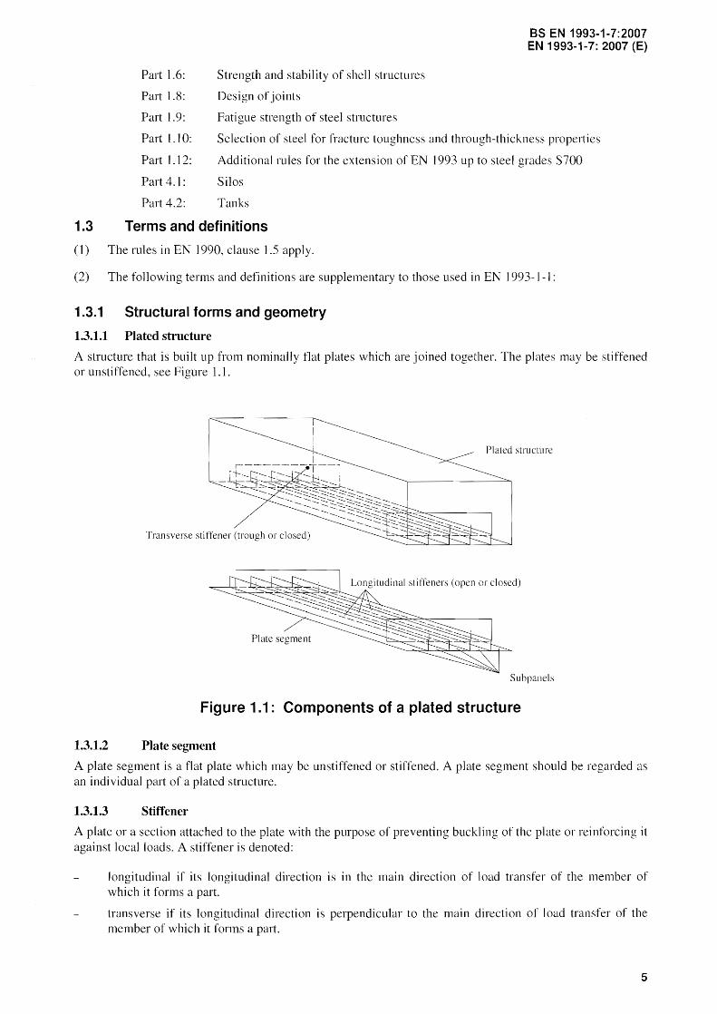
1.3.1.1 Plated structure
A structure that is built up from nominally flat plates which are joined together. The plates may be stiffened or unstiffened, see Figure 1.1.
Plmed structure
Transverse stiffener (trough or closed)
Plate segment
Subpancls
Figure 1.1: Components of a plated structure
1.3.1.2 Plate segment
A plate segment is a flat plate which may be unstiffened or stiffened. A plate segment should be regarded as an indi vidual palt of a plated structure.
1.3.1.3 Stiffener
A plate or a section attached to the plate with the purpose of preventing buckling of the plate or reinforcing it against local loads. A stiffener is denoted:
longitudinal if its longitudinal direction is in the main direction of load transfer of the member of which it forms a part.
transverse if its longitudinal direction is perpendicular to the main direction of load transfer of the member of which it forms a patt.
5
BS EN 1993-1-7:2007 EN 1993-1-7: 2007 (E)
1.3.1.4 Stiffened plate
Plate with transverse and/or longitudinal stiffeners.
1.3.1.5 Sub-panel
Unstiffened plate surrounded by stiffeners Of, on a web, by flanges andlor stiffeners or, on a flange, by webs andlor stiffeners.
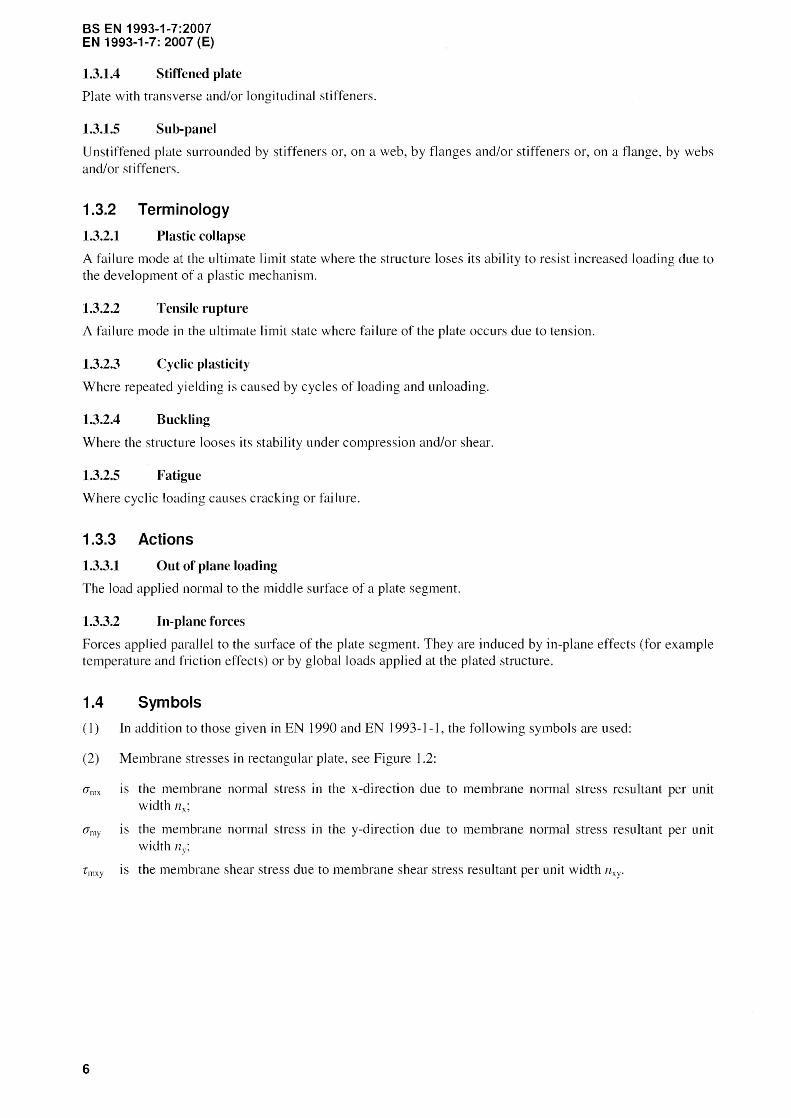
1.3.2 Terminology
1.3.2.1 Plastic colJapse
A failure mode at the ultimate limit state where the structure loses its ability to resist increased loading due to the development of a plastic mechanism.
1.3.2.2 Tensile rupture
A failure mode in the ultimate limit state where failure of the plate occurs due to tension.
1.3.2.3 Cyclic plasticity
Where repeated yielding is caused by cycles of loading and unloading.
1.3.2.4 Buckling
Where the structure looses its stability under compression and/or shear.
1.3.2.5 Fatigue
Where cyclic loading causes cracking or failure.
1.3.3 Actions
1.3.3.1 Out of plane loading
The load applied normal to the middle surface of a plate segment.
1.3.3.2 In-plane forces
Forces applied para]]el to the surface of the plate segment. They are induced by in-plane effects (for example temperature and friction effects) or by global loads applied at the plated structure.
1.4 Symbols
(1) In addition to those given in EN 1990 and EN I -I, the following symbols are used:
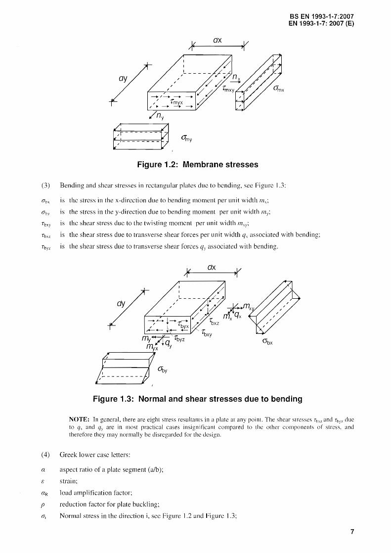
(2) Membrane stresses in rectangular plate, see Figure 1.2:
O"mx
amy
Tmxy
6
is
IS
is
the membrane normal stress in the x-direction due to membrane normal stress resultant per unit width i2x;
the membrane normal stress in the y-direction due to membrane normal stress resultant per unit width lly;
the membrane shear stress due to membrane shear stress resultant per unit width
BS EN 1993-1-7:2007 EN 1993-1-7: 2007 (E)
/---+---+ ---+
/ rmyx r--+---+---+---+
Figure 1.2: Membrane stresses
(3) Bending and shear stresses in rectangular plates due to bending, see Figure 1.3:
O'bx is
O'by is
Tbxy is
Tbxz is
Tbyz is
the stress in the x-direction due to bending moment per unit width mx~
the stress in the y-direction due to bending moment per unit width 171y;
the shear stress due to the twisting moment per unit width l11 xy ;
the shear stress due to transverse shear forces per unit width qx associated with bending;
the shear stress due to transverse shear forces qy associated with bending.
ax /.r+-~----...,,(
Figure 1.3: Normal and shear stresses due to bending
NOTE: In general, there are eight stress resultants in a plate at any point. The shear stresses Tim and Tbyz due to qx and qy are in most practical cases insignificant compared to the other components of stress, and therefore they may normaHy be disregarded for the design.
(4) Greek lower case letters:
a aspect ratio of a plate segment (alb);
c: strain;
aR load amplification factor;
p reduction factor for plate buckling;
O'j Normal stress in the direction i, see Figure 1.2 and Figure 1.3;
7

BS EN 1993-1-7:2007 EN 1993-1-7: 2007 (E)
T Shear stress, see Figure 1.2 and Figure 1
v Poisson's ratio;
J!M partial factor.
(5) Latin upper case letter:
E Modulus of elasticity
(6) Latin lower case letters:
a length of a plate segment, see Figure] .4 and Figure 1
b width of a plate segment, see Figure 1.4 and Figure 1.5;
yield stress or 0,2% proof stress for material with non linear stress-strain curve;
l1j membrane normal force in the direction i [kN/m];
I1xy membrane shear force [kN/m}
III bending moment [kNm/m];
qz transverse shear force in the z direction [kN/m];
thickness of a plate segment, see figure 1.4 and 1.5.
NOTE: Symbols and notations which are not listed above are explained in the text where they first appear.
y,v~. I 'xu
Z,W
Figure 1.4: Dimensions and axes of unstiffened plate segments
y.v---1'"" J x,u
Z,YIi'
Figure 1.5: Dimensions and axes of stiffened plate segments; stiffeners may be open or closed stiffeners
8
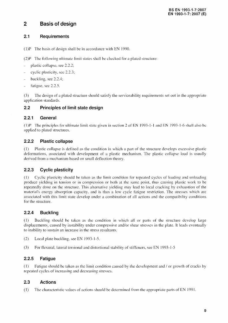
2 Basis of design
2.1 Requirements
(l)P The basis of design shall be in accordance with EN 1990.
(2)P The following ultimate limit states shall be checked for a plated structure:
plastic collapse, see 2.2.2;
cyclic plasticity, see 2.2.3;
buckling, see
fatigue, see 2.2.5.
BS EN 1993-1-7:2007 EN 1993-1-7: 2007 (E)
(3) The design of a plated structure should satisfy the serviceability requirements set out in the appropriate application standards.
2.2 Principles of lin"lit state design
2.2.1 General
(l)P The principles for ultimate limit state given in section 2 of EN 1993-1-1 and EN 1993-1-6 shall also be applied to plated structures.
2.2.2 Plastic collapse
(1) Plastic co]]apse is defined as the condition in which a part of the structure develops excessive plastic deformations, associated with development of a plastic mechanism. The plastic collapse load is llsually derived from a mechanism based on small deflection theory.
2.2.3 Cyclic plasticity
(I) Cyclic plasticity should be taken as the limit condition for repeated cycles of loading and unloading produce yielding in tension or in compression or both at the same point, thus causing plastic work to be repeatedly done on the structure. This alternative yielding may lead to local cracking by exhaustion of the material's energy absorption capacity, and is thus a low cycle fatigue restriction. The stresses which are associated with this limit state develop under a combination of all actions and the compatibility conditions for the structure.
2.2.4 Buckling
(1) Buckling should be taken as the condition in which all or paI1S of the structure develop large displacements, caused by instability under compressive andlor shear stresses in the plate. It leads eventually to inability to sustain an increase in the stress resultants.
(2) Local plate buckling, see EN 1993-1-5.
(3) For flexural, lateral torsional and distortional stability of stiffeners, see EN 1993-1-5
2.2.5 Fatigue
(1) Fatigue should be taken as the limit condition caused by the development and I or growth of cracks by repeated cycles of increasing and decreasing stresses.
2.3 Actions
(1) The characteristic values of actions should be determined from the appropriate pm1s of EN 199].
9

BS EN 1993-1-7:2007 EN 1993-1-7: 2007 (E)
2.4 Design assisted by testing
(I) For design assisted by testing reference should be made to section 2.5 of EN 1993-1-1 and where releva.nt, Section 9 of EN ] 993-1-3.
3 Material properties
(]) This Standard covers the design of plated structures fabricated from steel material conforming to the product standards listed in EN 1993-1-1 and EN 1993-1 -] 2.
(2) The material properties of cold formed members and sheeting shou Id be obtained from EN 1993-1-3.
(3) The material properties of stainless steels should be obtained from EN 1993-1-4.
4 Durability
( 1 ) For durabi Iity see section 4 of EN ] 993-1 1.
5 Structural analysis
5.1 General
( I)P The models used for calculations shall be appropriate for predicting the structural behaviour and the limit states considered.
(2) If the boundary conditions can be conservatively defined, i.e. restrained or unrestrained, a plated structure may be subdivided into individual plate segments that may be analysed independently.
(3)P The overall stability of the complete structure shall be checked following the relevant parts of EN 1993.
5.2 Stress resultants in the plate
5.2.1 General
(]) The calculation model and basic assumptions for determining internal stresses or stress resultants should correspond to the assumed structural response for the ultimate limit state loading.
(2) Structural models may be simplified such that it can be shown that the simpllfications used will give conservative estimates of the effects of actions.
(3) Elastic global analysis should generally be used for plated structures. Where fatigue is likely to occur, plastic global analysis should not be used.
(4) Possible deviations from the assumed directions or positions of actions should be considered.
(5) Yield line analysis may be used in the ultimate limit state when inplane compression or shear is less than I of the corresponding resistance. The bending resistance in a yield line should be taken as
111 Rd
5.2.2 Plate boundary conditions
(I) Boundary conditions assumed in analyses should be appropriate to the limit states considered.
10
BS EN 1993-1-7:2007 EN 1993-1-7: 2007 (E)
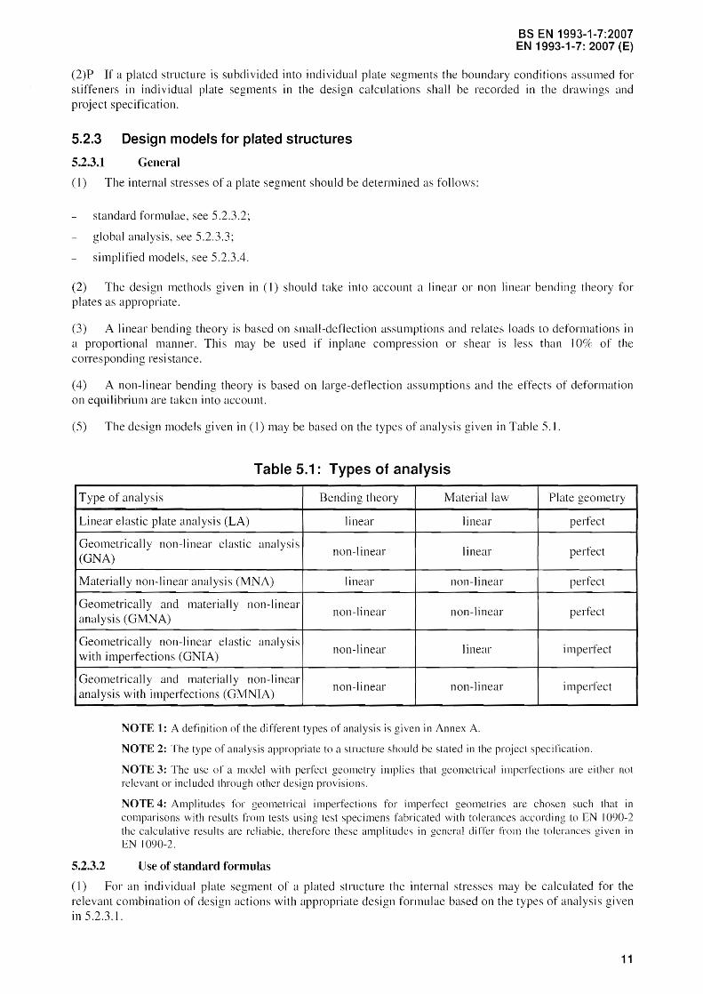
(2)P If a plated structure 1S subdivided into individual plate segments the boundary conditions assumed for stiffeners in individual plate segments in the design calculations shall be recorded in the drawings and project specification.
5.2.3 Design models for plated structures
5.2.3.1 General
(]) The internal stresses of a plate segment should be determined as follows:
standard formulae, see 5.2.3.2:
global analysis, see 5.2.3.3;
simplified models, see 5.2.3.4.
(2) The design methods given in (]) should take into account a linear or non linear bending theory for plates as appropriate.
(3) A linear bending theory is based on small-deflection assumptions and relates loads to deformations in a proportional manner. This may be used if inplane compression or shear is less than 10% of the corresponding resistance.
(4) A non-linear bending theory is based on large-deflection assumptions and the effects of deformation on equilibtium are taken into account.
(5) The design models given in (I) may be based on the types of analysis given in Table 5. J.
Table 5.1: Types of analysis
Type of analysis Bending theory Material law Plate geometry
Linear elastic plate analysis (LA) linear linear perfect
Geo metri call y non-linear elastic analysis non-linear linear perfect
(GNA)
Materially non-linear analysis (l\1NA) linear non-linear perfect
Geometrically and materially non-linear non-linear non-linear perfect
analysis (GMNA)
Geometrically non-linear elastic analysis non-linear linear imperfect
with imperfections (GNIA)
Geometrically and material I y non-linear non-linear non-linear imperfect
analysis with imperfections (GMNIA)
NOTE 1: A definition of the different types of analysis is given in Annex A.
NOTE 2: The type of analysis appropriate to a structure should be stated in the project specification.
NOTE 3: The use of a model with perfect geometry implies that geometrical imperfections are either not relevant or included through other design provisions.
NOTE 4: Amplitudes for geometrical imperfections for imperfect geometries are chosen such that in comparisons with results from tests using test specimens fabricated with tolerances according to EN 1090-2 the calculati ve results are reliable. therefore these amplitudes in general di ITer from the tolerances given in EN 1090-2.
5.2.3.2 Use of standard fonnulas
(1) For an individual plate segment of a plated structure the internal stresses may be calculated for the relevant combination of design actions with appropriate design formulae based on the types of analysis given in 5.2.3.1.
11

BS EN 1993-1-7:2007 EN 1993-1-7: 2007 (E)
NOTE: Annex B and Annex C provide tabulated values for rectangular unstiffened plates which are loaded transversely. For circular plates design formulas are given in EN 1993-1-6. Further design formulas may be used, i r the reliability of the design formulas is in accordance with the requirements given in EN 1991-1.
(2) In case of a two dimensional stress field resulting from a membrane theory analysis the equivalent Von M ises stress (Jeq.Ed may be determined by
(5.1)
(3) In case of a two dimensional stress field resulting from an elastic plate theory the equivalent Yon Mises stress 0t:q.Ed may be determined, as follows:
(5.2)
where (J xJ' d =
(Jy.Ed =
r xy.Ed
and llx.Ed, lnx.Fd, my.Ed and are defined in IA( I) and (2).
NOTE: The above expressions give a simplified conservative equivalent stress for design
5.2.3.3 Use of a global analysis: numerical analysis
(]) If the internal stresses of a plated structure are determined by a numerical analysis which is based on a materially linear analysis, the maximum equivalent Von Mises stress of the plated structure should be calculated for the relevant combination of design actions.
(2) The equivalent Von ~1ises stress O'eq.Ed is defined by the stress components which occurred at one point in the plated structure.
(5.3)
where ax.Ed and are positive in case of tension.
(3) If a numerical analysis is used for the verification of buckling, the effects of imperfections should be taken into account. These imperfections may be:
(a) geometrical imperfections:
deviations from the nominal geometric shape of the plate (initial deformation, out of plane deflections);
irregularities of welds (minor eccentricities);
deviations from nominal thickness.
(b) material impelfections:
12
residual stresses because of rolling, pressing, welding, straightening;
non-homogeneities and anisotropies.
BS EN 1993·1·7:2007 EN 1993·1·7: 2007 (E)
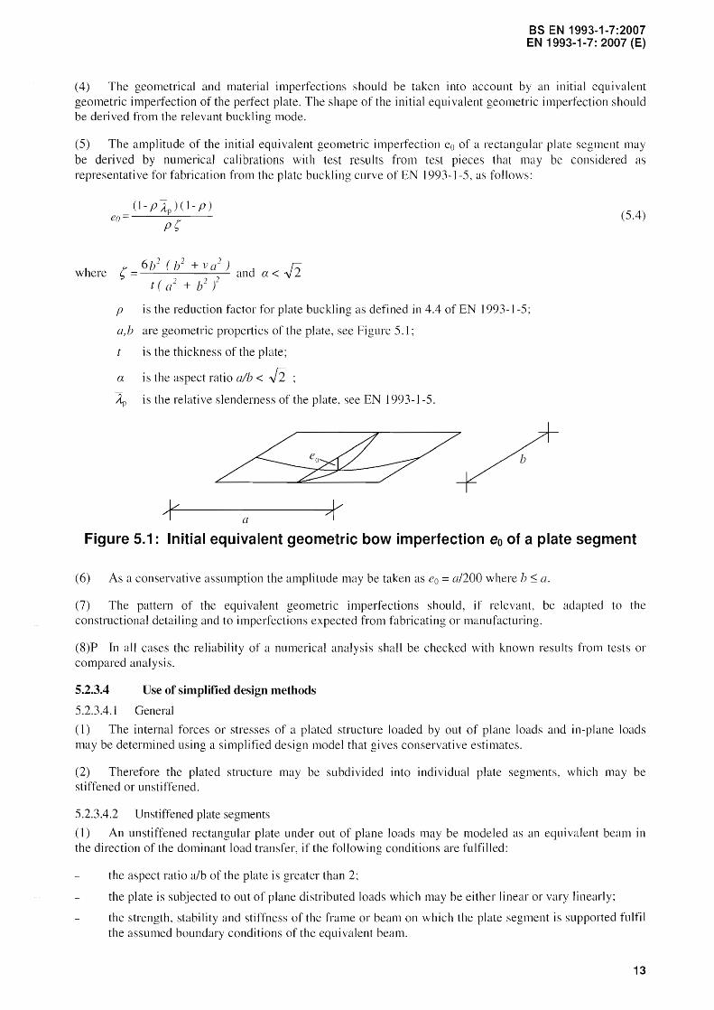
(4) The geometrical and material imperfections should be taken into account by an initial equivalent geometric imperfection of the pelfect plate. The shape of the initial equivalent geometric imperfection should be derived from the relevant buckling mode.
(5) The amplitude of the initial equivalent geometric imperfection eo of a rectangular plate segment may be derived by numerical calibrations with test results from test pieces that may be considered as representative for fabrication from the plate buckling curve of EN 1993-1 as follows:
where
eo
? =:.: 6b2
( 1/
t ( + b2 l and a < -J2
p is the reduction factor for plate buckling as defined in 4.4 of EN 1993-1-5:
a, b are geometric propelties of the plate, see Figure 5.1 ;
is the thickness of the plate;
a is the aspect ratio alb < -J2 ~) is the relative slenderness of the plate, see EN 1993-1-5.
(5.4)
Figure 5.1: Initial equivalent geometric bow imperfection eo of a plate segment
(6) As a conservative assumption the amplitude may be taken as eo = a/200 where b :s; a.
(7) The pattern of the equivalent geometric imperfections should, if relevant, be adapted to the constructional detailing and to imperfections expected from fabricating or manufacturing.
(8)P In all cases the reliability of a numerical analysis shall be checked with known results from tests or compared analysis.
5.2.3.4 Use of simplified design methods
5.2.3.4.1 General
(I) The internal forces or stresses of a plated structure loaded by out of plane loads and in-plane loads may be determined using a simplified design model that conservative estimates.
(2) Therefore the plated structure may be subdivided into individual plate segments, which may be stiffened or unstiffened.
5.2.3.4.2 Unstiffened plate segments
(1) An unstiffened rectangular plate under out of plane loads may be modeled as an equivalent beam in the direction of the dominant load transfer, if the following conditions are fulfilled:
the aspect ratio alb of the plate is greater than 2;
the plate is subjected to out of plane distributed loads which may be either linear or vary Jinearly;
the strength, stability and stiffness of the frame or beam on which the plate segment is supported fulfil the assumed boundary conditions of the equivalent beam.
13

BS EN 1993-1-7:2007 EN 1993-1-7: 2007 (E)
(2) The internal forces and moments of the equivalent beam should be determined using an elastic or plastic analysis as defined in EN 1993-1 I.
(3) If the first order deflections due to the out of plane loads is similar to the (plate) buckling mode due to the in plane compression forces, the interaction between both phenomena need to be taken into account.
(4) In cases where the situation as described in (3) is present the interaction formula specified in EN ] 993-1 1, section 6.3.3 may be applied to the equivalent beam.
5.2.3.4.3 Stiffened plate segments
(l) A stiffened plate or a stiffened plate segment may be modeled as a grillage if it is regularly stiffened in the transverse and longitudinal direction.
(2) In determining the cross-sectional area Ai of the cooperating plate of an individual member i of the grillage the effects of shear should be taken into account by the reduction factor f3 according to EN1993-J -5.
(3) For a member i of the grillage which is arranged in parallel to the direction of inplane compression forces, the cross-sectional area Ai should also be determined taking account of the effecti ve width of the adjacent subpanels due to plate buckling according to EN 1993-1-5.
(4) The interaction between shear lag effects and plate buckling effects, see Figure 5.2, should be considered by the effective area Ai from the following equation:
where
)] f3K (5.5)
is the effective area of the stiffener considering to local plate buckling of the stiffener;
Pc is the reduction factor due to global plate buckling of the stiffened plate segment, as defined in 4.5.4(1) oLEN 1993-1-5;
Pp'1Il.i is the reduction factor clue to local plate buckling of the subpanel i, as defined in 4.4( I) of EN 1993-1-5;
bpan•i is the width of the subpanel i, as defined in 4.5.1 of EN 1993-1-5;
tpan.i is the thickness of the subpanel i;
f3 is the effecti ve width factor for the effect of shear see 1 of EN 1993-1-5;
K is the ratio defined in 3.3 of EN ] 993-1-5.
~~.HdS .~_T~a_n~v_~~~~_~tiffe_~_~r __ ml ~.~X'Ed_
NEd' ± b. $3 NEd 1:=:::::r=:::;::::==::::::1
~----------------~ qEd t~-+-+ __ ~+ qEd
~Ai Figure 5.2: De'finition of the cross-section Ai
(5) The verification of a member i of the grillage may be performed using the interaction formula in EN ] 993-1-1, section 6.3.3 taking into account the following loading conditions:
effects of out of plane loadings;
equivalent axial force in the cross section Ai due to norma] stresses in the plate;
14
BS EN 1993-1-7:2007 EN 1993-1-7: 2007 (E)
eccentricity e of the equivalent axial force sectional area Ai.
with respect to the centre of gravity of the cross-
(6) If the stiffeners of a plate or a plate segment are only arranged in parallel to the direction of inplane compression forces, the stiffened plate may be modeled as an equivalent beam on elastic springs, see EN 1993-l-5.
(7) If the stiffeners of a stiffened plate segment are positioned in the transverse direction to the compression forces, the interaction between the compression forces and bending moments in the unstiffened plate segments between the stiffeners should be verified according to 5.2.3.4.2(4).
(8) The longitudinal stiffeners should fulfill the requirements given in section 9 of EN 1993-1-5.
(9) The transverse stiffeners should fulfill the requirements given in section 9 of EN 1993- J -5.
6 Ultimate limit state
6.1 General
(1)P All parts of a plated structure shall be so proportioned that the basic design requirements for ultimate limit states given in section 2 are satisfied.
(2) For the partial factor YM for resistance of plated structures see the relevant application pUl1S of EN 1993.
(3) For partial factor YM of connections of plated structures see EN ] 993-1-8.
6.2 Plastic limit
6.2.1 General
(1) At every point in a plated structure the design stress aeq.Ed should satisfy the condition:
(6.1 )
where aeq,Ed is the largest value of Von Mises equivalent stress as defined in 5.2.3.
(2) In an elastic design the resistance of a plate segment against plastic collapse or tensile rupture uncler combined axial forces and bending is defined by the Von Mises equivalent stress as:
aeq,Rd = fyk / I'MO (6.2)
NOTE: For the numerical value of %,10 see 1.1 (2).
6.2.2 Supplementary rules for the design by global analysis
(1) If a numerical analysis is based on materially linear analysis the resistance against plastic collapse or tensile rupture should be checked for the requirement given in 6.2.1.
(2) If a materially nonlinear analysis is based on a design stress-strain relationship with f;iCI. (=f/YMO) the plated structure should be subject to a load arrangement FEd that is taken from the design values of actions, and the load may be incrementally increased to determine the load amplification factor 0:1{ of the plastic limit state FRd.
(3) The result of the numerical analysis should satisfy the condition:
FEd ~ (6.3)
where F Rd O:R FEd
15

BS EN 1993~1*7:2007 EN 1993~1~7: 2007 (E)
(XR is the load amplification factor for the loads FEd for reaching the ultimate limit state.
6.2.3 Supplementary rules for the design by simplified design methods
6.2.3.1 Unstiffened plates
(1) If an unstiffened plate is designed as an equivalent beam, its cross-sectional resistance should be checked for the combination of inplane loading and out of plane loading effects with the design rules given in EN 1993-1-1.
6.2.3.2 Stiffened plates
(1) If a stiffened plate segment is modeled as a grillage as described in section 5.2.3.4 the cross-section resistance and the buckling resistance of the individual members i of the grillage should be checked for the combination of inplane and out of plane loading effects using the interaction formula in EN 1993-1-1, section 6.3.3.
(2) If a stiffened plate segment is designed as an equivalent beam as described in section 5.2.3.4 the crosssection resistance and the buckling resistance of the equivalent beam should be checked for the combination of inplane and out of plane loading effects using the interaction formula in EN 1993-1-1, section 6.3.3.
(3) The stress resultants or stresses of a subpanei should be verified against tensile rupture or plastic collapse witb the design rules given in 5.2.3.2, 5.2.3.3 or 5.2.3.4.
6.3 Cyclic plasticity
6.3.1 General
(I) At every point in a plated structure the design stress range should satisfy the condition:
(6.4)
where~O"Eci is the largest value of the Von Mises equivalent stress range
L!CJ'eq,Ed
at the relevant point of the plate segment due to the relevant combination of design actions.
(2) Tn a materially linear design the resistance of a plate segment against cyclic plasticity / low cycle fatigue may be verified by the Von Mises stress range limitation ~O"Rd.
(6.5)
NOTE: For the numerical value of n,10 see 1.1 (2).
6.3.2 Supplementary rules for the design by global analysis
(I) Where a materially nonlinear computer analysis is carried out, the plate should be subject to the design values of the actions.
(2) The total accumulated Von Mises equivalent strain ~q,Ed at the end of the design life of the structure should be assessed using an analysis that models all cycles of loading.
(3) Unless a more refined analysis is carried out the total accumulated Von Mises equivalent plastic strain ~q.Ed may be determined from:
where: 111
16
= 111 ~£eq.EcJ (6.6)
is the number of cycles in the design life:
is the largest increment in the Von Mises plastic strain dl1ring one complete load cycle at any point in the structure occU1Ting after the third cycle,
BS EN 1993·1-7:2007 EN 1993-1-7: 2007 (E)
(4) Unless a more sophisticated low cycle fatigue assessment is undertaken, the design value of the total accumulated Von Mises equivalent plastic strain Eeq.Ed should satisfy the condition
6.4
6.4.1
NOTE 1: The National Annex may choose the value of
NOTE 2: For the numerical value of nl0 see 1.1
Buckling resistance
General
The value l1cq = 25 is recommended.
(6.7)
(l) If a plate segment of a plated structure is loaded by in-plane compression or shear, its resistance to plate buckling should be verified with the design rules given in EN 1993-1-5.
(2) Flexural, lateral torsional or distortional stability of the stiffness should be verified according to EN 1993-1 see also 5.2.3.4 (8) and (9)
(3) For the interaction between the effects of in-plane and Ollt of plane loading, see section 5.
6.4.2 Supplementary rules for the deSign by global analysis.
(l) If the plate buckling resistance for combined in plane and out of plane loading is checked by a numerical analysis, the design actions FEd should satisfy the condition:
(6.8)
(2) The plate buckling resistance FRd of a plated structure is defined as:
(6.9)
whereFRk is the characteristic buckling resistance of the plated structure
k is the calibration factor, see (6).
NOTE: For the numerical value of f}.11 see 1.1
The characteristic buckling resistance FRk should be derived from a load-deformation curve which is calculated for the relevant point of the structure taking into account the relevant combination of design actions In addition, the analysis should take into account the imperfections as described in 5.2.3.2.
(4) The characteristic buckling resistance FRk is defined by either of the two fol1owing criterion:
maximum load of the load-deformation-curve (limit load);
maximum tolerable deformation in the load deformation curve before reaching the bifurcation load or the Ii mit load, if relevant.
(5) The reliability of the numerical1y determined critical buckling resistance should be checked:
(a) either by calculating other plate buckling cases, for which characteristic buckling resistance values FRk,known are known, with the same basically similar imperfection assumptions. The check cases should be similar in their buckling controlling parameters (e.g. non-dimensional plate slenderness, post buckling behaviour, imperfection-sensitivity, material behaviour)~
(b) or by comparison of calculated values with test results FRk,kIlOWIl'
(6) Depending on the results of the reliability checks a calibration factor k should be evaluated from:
k 1'''.rdIU''ill.l:lltTK / F Rk.ch.:ck (6.10)
17
B5 EN 1993-1-7:2007 EN 1993-1-7: 2007 (E)
where FRk.kIlCl\\Il.cht:ck as fo]]ows from prior knowledge;
are the results of the numerical calculations.
6.4.3 Supplementary rules for the design by simplified design methods
(I) If a stiffened plate segment is subdivided into subpanels and equivalent effective stiffeners as described in section 5.2.3.4 the buckling resistance of the stiffened plate segment may be checked with the design rules given in EN 1993-1-5. Lateral buckling of free stiffener-flanges may be checked according to EN 1993-1-1, section 6.3.3.
(2) The buckling resistance of the equivalent effective stiffener which is defined in section 5.2.3.4 of the plate may be checked with the design rules given in EN 1993-1-1.
7 Fatigue
(I) For plated structures the requirements for fatigue should be obtained from the relevant application standard of EN 1993.
(2) The fatigue assessment should be carried out according to the procedure given in EN 1993-1-9.
8 Serviceability limit state
8.1 General
(I) The principles for serviceability limit state given in section 7 of EN 1993-1-1 should also be applied to plated structures.
(2) For plated structures especial1y the limit state criteria given in 8.2 and 8.3 should be verified.
8.2 Out of plane detlection
(1) The limit of the out of plane deflection w should be defined as the condition in which the effective use of a plate segment is ended.
NOTE For limiting values of out of plane deflection w see application standard.
8.3 Excessive vibrations
(l) Excessive vibrations should be defined as the limit condition in which either the failure of a plated structure OCCLlrs by fatigue caused by excessive vibrations of the plate or serviceability limits apply.
NOTE: For limiting values of slenderness to prevent excessive vibrations see application standard.
18

BS EN 1993-1-7:2007 EN 1993-1-7: 2007 (E)
Annex A [informative] - Types of analysis for the design of plated structures
A.1 General
(I) The internal stresses of stiffened and unstiffened plates may be determined with the following types of analysis:
LA: Linear elastic analysis;
GNA: Geometrically nonlinear analysis:
MNA: .Materially nonlinear analysis;
Gl\1NA: Geometrically and materially nonlinear analysis;
GNIA: Geometrically nonlinear analysis elastic with imperfections included;
GMNIA: Geometrically and materially nonlinear analysis with imperfections included.
A.2 Linear elastic plate analysis (LA)
(]) The linear elastic analysis models the behaviour of thin plate structures on the basis of the plate bending theory, related to the perfect geometry of the plate. The linearity of the theory results from the assumptions of the linear elastic material law and the linear small detlection theory.
(2) The LA analysis satisfies the equilibrium as well as the compatibility of the deflections. The stresses and deformations vary linear with the out of plane loading.
(3) As an example for the LA analysis the following fourth-order partial differential equation is given for an isotropic thin plate that subject only to a out of plane load p(x,y):
Et' where D = ----
12 ( I - v2 )
A.3 Geometrically nonlinear analysis (GNA)
(A. I)
(l) The geometrically nonlinear elastic analysis is based on the principles of the plate bending theory of the perfect structure using the linear elastic material law and the nonlinear, deflection theory.
(2) The GNA analysis satisfies the equilibrium as well as the compatibility of the detlections under consideration of the deformation of the structure.
(3) The large deflection theory takes into account the interaction between flexural and membrane actions. The deflections and stresses vary in a non linear manner with the magnitude of the out of plane pressure.
(4) As an example for the GNA analysis the following fourth-order partial differential equation system is given for an isotropic thin plate subjected only to a Ollt of plane load p(x~y).
p(x,y)
D (A.2a)
(A.2b)
19

BS EN 1993-1-7:2007 EN 1993-1-7: 2007 (E)
where f is the Airy's stress function
D E t 3
A.4 Materially nonlinear analysis (MNA)
(I) The materia]]y nonlinear analysis IS based on the plate bending theory of the perfect structure with the assumption of small deflections - like in A.2 -, however, it takes into account the nonlinear behaviour of the material.
A.5 Geometrically and materially nonlinear analysis (GMNA)
(]) The geometrically and materially nonlinear analysis is based on the plate bending theory of the perfect structure with the assu mptions of the nonlinear, large deflection theory and the nonlinear, eJasto-pJastic material law.
A.6 Geometrica lIy nonlinear analysis elastic with imperfections included (GNIA)
(1) The geometrically nonlinear analysis with imperfections included is equivalent to the GNA analysis defined in A.3, however, the geometrical model used the geometrica]]y imperfect structure, for instance a predeformation applies at the plate which is governed by the relevant buckling mode.
(2) The GNTA analysis is used in cases of dominating compression or shear stresses in some of the plated structures due to in-plane effects. It delivers the elastic buckling resistance of the "real" imperfect plated structure.
A.7 Geometrically and materially nonlinear analysis with imperfections included (GMNIA)
(I) The geometrically and materially nonlinear analysis with imperfections included is equivalent to the GMNA analysis defined in A.S, however, the geometrical model used the geometrically imperfect structure, for instance a pre-deformation applies at the plate which is governed by the relevant buckling mode.
(2) The GMNIA analysis is used in cases of dominating compression or shear stresses in a plate due to in-plane effects. It delivers the elasto-plastic buckling resistance of the "real" imperfect structure.
20
BS EN 1993·1·7:2007 EN 1993·1·7: 2007 (E)
Annex B [informative] - Internal stresses of unstiffened rectangular plates from small deflection theory
B.1 General
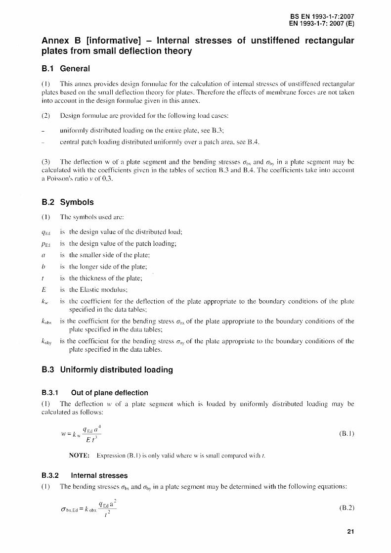
(I) This annex provides design formulae for the calculation of internal stresses of unstiffened rectangular plates based on the small deflection theory for plates. Therefore the effects of membrane forces are not taken into account in the design formulae given in this annex.
(2) Design formulae are provided for the following load cases:
uniformly distributed loading on the entire plate, see B.3;
central patch loading di stributed uniformly over a patch area, see B.4.
(3) The deflection w of a plate segment and the bending stresses O"hx and ahy in a plate segment may be calculated with the coefficients given in the tables of section B.3 and B.4. The coefficients take into account a Poisson's ratio v of 0,3.
B.2 Symbols
( 1) The symbol s used are:
qEd is the design value of the distributed load;
/JEd is the design value of the patch loading;
a is the smaller side of the plate;
b is the longer side of the plate;
is the thickness of the plate;
E is the Elastic modulus;
IS the coefficient for the deflection of the plate appropriate to the boundary conditions of the plate specified in the data tables;
kobx is the coefficient for the bending stress O"hx of the plate appropriate to the boundary conditions of the plate specified in the data tables;
is the coefficient for the bending stress ahY of the plate appropriate to the boundary conditions of the plate specified in the data tables.
B.3 Uniformly distributed loading
8.3.1 Out of plane deflection
(1) The deflection w of a plate segment which is loaded by uniformly distributed loading may be calculated as follows:
(B. 1)
NOTE: Expression (13.1) is only valid where w is small compared with t.
8.3.2 Internal stresses
(I) The bending stresses O"bx and aby in a plate segment may be determined with the following equations:
(B.2)
21

BS EN 1993-1-7:2007 EN 1993-1-7: 2007 (E)
() by. Eel k aoy t
2 (B.3)
(2) For a plate segment the equivalent stress may be calculated with the bending stresses given in (1) as follows:
() eq./:'d = (B.4)
NOTE: The points for whil:h the state of stress are defined in the data tables are located either on the centre lines or on the boundaries, so that due to symmetry or the postulated boundary conditions, the bending shear stresses Tb are zero.
8.3.3 Coefficients k for uniformly distributed loadings
Table B.1: Coefficients k
y~!I' Loading: Uniformly distributed loading
bI 11 ?
X Boundary conditions: AI] edges are rigidly supported and rotationally free
loE a ~I
bla kwl kahxl :aby
],0 0,04434 0,286 0,286
1,5 0,08438 0,486 0,299
2,0 0,] ]070 0,609 0,278
3,0 0,13420 0,712 0,244
Table B.2: Coefficients k
y4 Loading: Uniformly distributed loading
bI 1 2 or
Boundary conditions: x An edges are rigidly supported and rotational1y fixed.
\...;;
a ~I
bla kwl kGbxl kGbyl
1,0 0,01375 0,]360 0,1360 -0,308
1,5 0,02393 0,2180 0.1210 -0,454
2,0 0,02763 0,2450 0,0945 -0,498
3,0 0,02870 0,2480 0,0754 -0,505
22

bI
hla
1,5
2,0
bI
bla
1,0
1,.5
2,0
bI
bla
1,0
1,5
2,0
Table B.3: Coefficients k
y Loading: Uniformly distributed loading
4 1 Boundary conditions:
x Three edges are rigidly supported and rotationally free and one edge is rigidly
I~ a ~I supported and rotationally fixed.
k,:;bx I k Gbyl kGbx-l
0,04894 0,330 0,177 -0,639
0,05650 0,368 0,]46 -0,705
Table B.4: Coefficients k
y~ Loading: Uniformly distributed loading
4 1 Boundary conditions: ~
x Two edges are rigidly supported and rotationally free and two edges are
I~ a >1 rigidly supported and rotationally fixed.
kwl k Gbx I jby kGbx-l
0,02449 0,185 0,185 -0,375
0,04411 0.302 0,180 -0,588
0,05421 0,355 0,152 -0,683
Table B.5: Coefficients k
y Loading: Uniformly distributed
3 loading
_1 .. Boundary conditions: ... x Tvv'o opposite short edges
are clamped, the other two edges are simply supported.
I~ a >1 kwl 'Gby I ,by
0,02089 0,]45 0,197 -0,420
0,05803 0,348 0,274 -0,630
0,09222 0,519 0,284 -0,7]7
BS EN 1993-1-7:2007 EN 1993-1-7: 2007 (E)
23

as EN 1993-1-7:2007 EN 1993-1-7: 2007 (E)
y
b/a
1,5
Table 8.6: Coefficients k
1 2 x
Loading: Uniformly distributed loading
Boundary conditions: Two opposite long edges are clamped, the other two are simply supp0l1ed.
2,0 0,02852 -0,507
8.4 Central patch loading
8.4.1 Out of plane deflection
(I) The deflection w of a plate segment which is loaded by a central patch loading may be calculated as follows:
8.4.2 Internal stresses
(I) The bending stresses O'ln and O'by in a plate segment may be determined by the following formulas:
O"bx.Ed = k crbx
PEd O"by,Ed = k crbY-J
r
(B.5)
(B.6)
(B.7)
(2) For a plate segment the equivalent stress may be calculated with the bending stresses given in (l) as fo]]ows:
0" eq,Fd (B.8)
24

8.4.3 Coefficients k for patch loading
BS EN 1993-1-7:2007 EN 1993-1-7: 2007 (E)
Table B.7: Coefficients k
y ~~ Loading: Central patch loading
J ~~ Boundary conditions:
b ... All edges are rigidly v
. , ~~ ... x
supported and ,. ,1/ 1 rotationally free.
u
Parmneters: /
X ,I' (X = lila a jJ = via
bla ex xjJ kwl k crbxl k crbyl
1 0,1 x 0,1 0,1254 1,72 1,72
0,2 x 0,2 0,1210 1,.32 1,32
0,3 x 0,3 0,1126 1,04 1,04
0,2 x 0,3 0,1167 1,20 1,12
0,2 x 0,4 0,1117 1,10 0,978
],5 0,1 x 0,1 0,1664 1,92 1,70
0,2 x 0,2 0,1616 ],5 I 1,29
0,3 x 0,3 0,1528 1,22 1,0 I
0,2 x 0,3 0,1577 1,39 1,09
0,2 x 0,4 0,]532 1,29 0,953
2,0 0,] x 0,1 0,1795 1,97 1,67
0,2 x 0,2 0,1746 1,56 1,26
0,3 x 0,3 0,1657 ],28 0,985
0,2 x 0,3 0,1708 1,45 1,07
0,2 x 0,4 0,1665 1,35 0,929
3,0 0,1 x 0,1 0,1840 1,99 1,66
0,2 x 0,2 0,1791 1,58 1,25
0,3 x 0,3 0,170] 1,30 0,975
0,2 x 0,3 0,1753 1,47 ],06
0,2 x 0,4 0,17 J 1 1,37 0,918
25

BS EN 1993-1-7:2007 EN 1993-1-7: 2007 (E)
Annex C [informative] - Internal stresses of unstiffened rectangular plates from large deflection theory
C.1 General
(l) This annex provides design formulas for the calculation of internal stresses of unstiffened rectangular plates based on the deflection theory for plates.
The fonowing loading conditions are considered:
uniformly distributed loading on the entire plate, see C.3;
central patch loading distributed uniformly over the patch area, see CA.
(3) The bending and membrane stresses in a plate and the deflection \v of a plate may be calculated with the coefficients given in the tables of section C.3 and CA. The coefficients take into account a Poisson's ratio v of 0).
C.2 Symbols
(I) The symbols used are:
qEd ]s the design value of tbe load uniformly distributed over the total surface;
{JEd is the design value of the patch loading uniformly distributed over the surface it x v;
a is the smaller side of the plate;
b is the longer side of the plate;
E
FBC
MBC
is the thickness of the plate;
is the Elastic modulus;
flexural boundary conditions;
membrane boundary conditions;
IS the coefficient for the deflection of the plate appropriate to the boundary conditions specified in the data tables;
kGbx is the coefficient for the bending stress (}bx of the plate appropriate to the boundary conditions specified in of the plate in the data tables;
kGby is the coefficient for tbe bending stress aby of the plate appropriate to the boundary conditions specified in the data tables;
kmllx is the coefficient for the membrane stress amx of the plate appropriate to the boundary conditions specified in the data tables;
kcrmy is the coefficient for the membrane stress amy of the plate appropriate to the boundary conditions specified 111 the data tables.
C.3 Uniformly distributed loading on the total surface of the plate
C.3.1 Out of plane deflection
(1) The detlection w of a plate segment which is loaded by uniformly distributed loading may be calculated as follows:
w = kw q
26
Et
4 a
(C. I)

C.3.2 Internal stresses
BS EN 1993-1-7:2007 EN 1993-1-7: 2007 (E)
(1) The bending stresses O"bx and O"by in a plate segment may be determined with the following equations:
qEd 2 a
O"bx,Ed k0bx ? r
qEd 2 a
O"by,Ed k 0by t
2
(2) The membrane stresses O"mx and l1my in a plate segment may be determined as follows:
0" III X , Ed
O"my,Ed
k olllx
2 qEd a
k omy 2 t
(C.2)
(C.3)
(C.4)
(C.S)
(3) At the loaded surface of a plate the total stresses are calculated with the bending and membrane stresses given in (l) and (2) as follows:
O"x,Ed = - l1bx,Ed + l1mx,Ed (C.6)
O"y,Ed = - O"by,Ed + O"my,Ed (C.7)
(4) At the no-loaded surface of a plate the total stresses are determined with the bending and membrane stresses given in (I) and (2) as follows:
(C.8)
O"y,Ed = O"by,Ed + O"my,Ed (C.9)
(5) For a plate the equivalent stress O"v,Ed may be calculated with the stresses given in (4) as follows:
~ 2 ? <Jeq,Ed = <Jx,Ed + <Jy,Ed - <Jx,Ed <Jy,Ed (C.IO)
NOTE: The points for which the state of stress are defined in the data tables are located either on the centre lines or on the boundaries, so that due to symmetry or the postulated boundary conditions, membrane shearing stresses Till as well as bending shear stresses Tb are zero. The algebraic sum of the appropriate bending and membrane stresses at the points considered in the data tables gives the values of maximum and minimum surface stresses at these points.
27

BS EN 1993-1-7:2007 EN 1993-1-7: 2007 (E)
C.3.3 Coef'ficients k for uniformly distributed loadings
Table C.1: Coefficients k yA~ Loading:
Uniformly distributed loading -,.--'I' Boundary conditions:
11 12 FBC: Al1 edges are simply supported.
b .. MBC: Zero direct stresses, zero shear stresses ...
X Parameters: \~ FBC MBC
qEd 4
-'--
Q = ({
E t 4
loE a )01
b/a Q klVl k Cibxl k Cibvl karnxl k 01Tlvi kol11vl.
1,0 20 0,0396 0,2431 02431 0,0302 0,0302 -0,0589 40 0,0334 0,1893 0,1893 0,0403 0,0403 -0,0841 12O 0,0214 0,0961 0,0961 0,0411 0,0411 -0,1024 200
I 0,0166 0,0658 0,0658 0,0372 0,0372 -0,1004
300 0,0135 0,0480 0,0480 0,0335 0,0335 -0,0958 400 0,0116 0,0383 0,0383 0,0306 0,0306 -0,0915
],5 20 0,0685 0,3713 0,2156 0,0243 0,0694 -0,1244 40 0,0546 0,2770 0,1546 0,0238 0,0822 -0,1492 120 0,0332 0,1448 0,0807 0,0170 0,0789 -0,1468 200 0,0257 0,1001 0,0583 0,0141 0,0715 -0,1363 300 0,0207 0,0724 0,0440 0,0126 0,0646 -0,1271 400 0,0176 0,0569 0,0359 0,0117 0,0595 -0,1205
2,0 20 0,0921 0,4909 0,2166 0,0085 0,0801 -0,] 346 40 0,0746 0,3837 0,1687 0,0079
I
0,0984 -0,] 657 120 0,0462 0,2138 0,0959 0,0073 I 0,0992 -0,1707 200 0,0356 0,1516 0,0695 0,0067 0,09]4 -0,1610 300 0,0287 0,112 ] 0,0528 0,0061 0,0840 -0,1510 400 0,0245 0,0883 0,0428 0,006] 0,0781 -0,1434
28
y ~
'-;.-,~
b 1 2 .. r
x
\I FBC -'--
Ie:; a ;>1
bla Q kwl
] 20 I 0,0369 40 0,0293 120 0,0170 200 0,0126 300 0,0099 400 0,0082
1,5 20 0,0554 40 0,0400 120 0,0214 200 0,0157 300 0,0122 400 0,0103
2 20 0,0621 40 0.0438 120 0,0234 200 0,0172 300 0,0135 400 0,0113
3 20 0,0686 40 0,0490 120 0,0267 200 I 0,0196 300 0.0153 400 0,0]27
BS EN 1993-1-7:2007 EN 1993-1-7: 2007 (E)
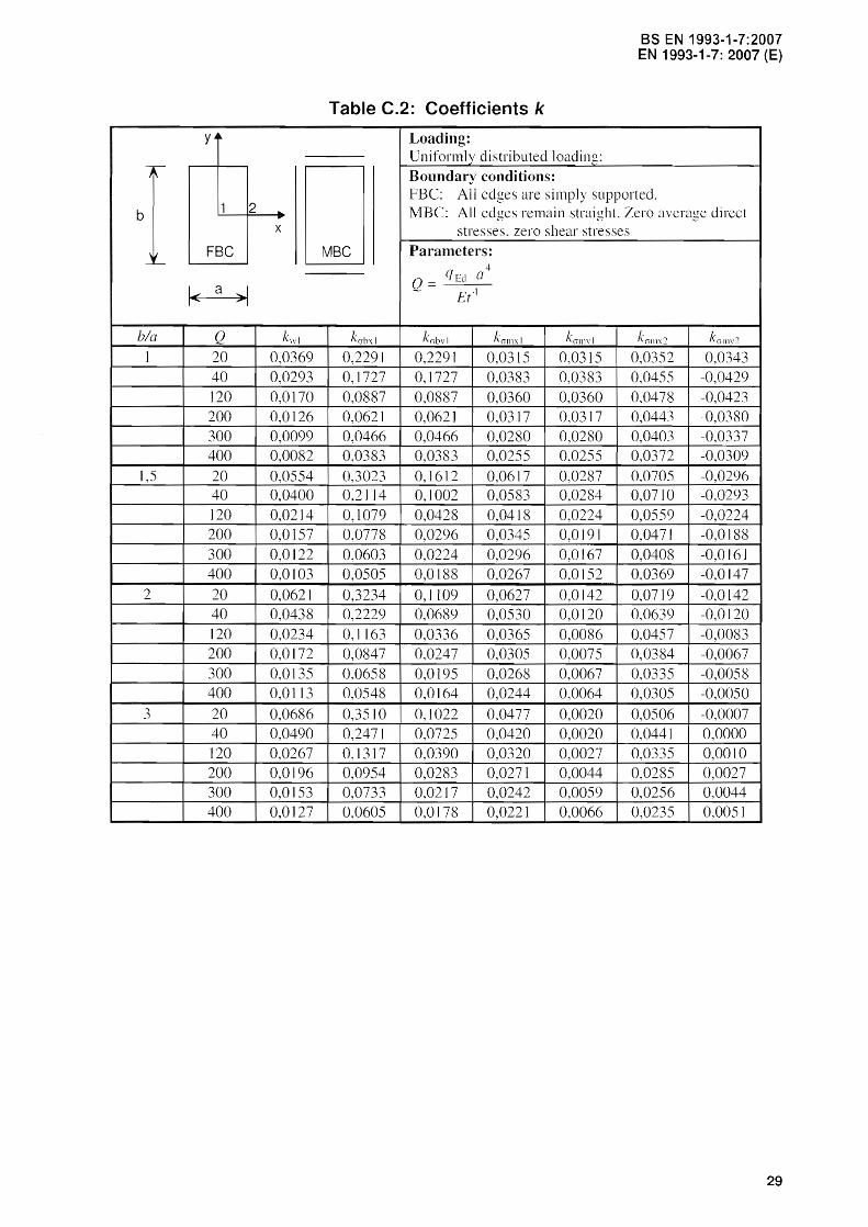
Table C.2: Coefficients k
Loading: Uniformly distributed ]oadin~:
Boundary conditions: FBC: All edges are simply supported. l'vlBC: All remain straight. Zero average direct
stresses. zero shear stresses
MBC Paranleters: 4
Q= qEd a E(~
ku\1xl kubvi k0ll1 :\ 1 kullWI k011lx1 k0111\j2
0,2291 02291 0,0315 0,0315 0,0352 -0.0343 0,1727 0,1727 0.0383 0,0383 0,0455 -0,0429 0,0887 0,0887 0,0360 0.0360 0,0478 -0,0423 0,0621 0,062] 0,0317 0,0317 0,0443 -0.0380 0,0466 0,0466 0,0280 0,0280 0,0403 -0,0337 0,0383 0,0383 0,0255 0.0255 0,0372 -0.0309 0.3023 0.1612 0,0617 0,0287 0,0705 -0,0296 0.21 ]4 0,1002 0,0583 0,0284 0,0710 -0,0293 0,1079 0,0428 0,0418 0,0224 0,0559 -0,0224 0.0778 0,0296 0,0345 0,0191 0.0471 -0,0188 0.0603 0.0224 0.0296 0,0167 0,0408 -0,0161 0,0505 0,0188 0,0267 0,0152 0,0369 -0,0147 0,3234 0,1109 0,0627 0.0142 0.0719 -0.0142 0,2229 0,0689 0,0530 0,0120 0.0639 -0.0120 0,1163 0.0336 0,0365 0,0086 0.0457 -0,0083 0,0847 0.0247 0.0305 0,0075 0,0384 -0,0067 0.0658 0,0195 0,0268 0,0067 0,0335 -0,0058 0,0548 0,0164 0,0244 0,0064 0,0305 -0,0050 0,3510 0,1022 0.0477 0,0020 0,0506 -0,0007 0,2471 0,0725 0,0420 0,0020 0,0441 0,0000 0,1317 0,0390 0,0320 0,0027 0,0335 0,0010
I 0,0954 0,0283 0,0271 0,0044 0,0285 0,0027 0,0733 0.0217 0,0242 0,0059 0,0256 0,0044 0,0605 0,0178 0.0221 0,0066 0,0235 0,0051
29

as EN 1993-1-7:2007 EN 1993-1-7: 2007 (E)
yA~
-,---
"
b 1
\/ FBC -'----
I~ a
h/a Q I 20
40 120 200 300 400
1,5 20 40 120 200 300 400
2 20 40 120 200 300 400
3 20 40 120 200 250
30
2 .. X
~I
kwl
0,0136 0,0131 0,0108 0,0092 0,0078 0,0069 0,0234 0,0222 0,0173 0,0144 0,0122 0,0107 0,0273 0,0265 0,0223 0,0192 0,0165 0,0147 0,0288 0,0290 0,0281 0,0260 0,0247
Table C.3: Coefficients k
Loading: Uniformly distributed loading:
Boundary conditions: FBC: All edges are clamped. MBC: Zero direct stresses, zero shear stresses
Parameters:
rvlBC qEd a 4
Q= £(1,
k0b'\l kobvl k olllxl k ollwl k 0bx ? k 01llV ?
0,1336 0,1336 0,0061 0,0061 -0,3062 -0,0073 0,1268 0,1268 0,0113 0,0113 -0,3006 -0,0137 0,0933 0,0933 0,0212 0,0212 -0,2720 -0,0286 0,0711 0,0711 0,0233 0,0233 -0,2486 -0,0347 0,0547 0,0547 0,0233 0,0233 -0,2273 -0,0383 0,0446 0,0446 0,0226 0,0226 -0,2113 -0,0399 0,2117 0,1162 0,0061 0,0133 -0,4472 -0,0181 0,1964 0,1050 0,0098 0,0234 -0,4299 -0,0322 0,1406 0,0696 0,0124 0,0385 -0,3591 -0,0559 0,1103 0,0537 0,0116 0,0415 -0,3160 -0,0620 0,0879 0,0430 0,0105 0,0416 -0,2815 -0,0636 0,0737 0,0364 0,0098 0,0409 -0,2583 -0,0635 0,2418 0,0932 0,0010 0,0108 -0,4935 -0,0 I SO 0,2330 0,0897 0,0017 0,0198 -0,4816 -0,0277 0,1901 0,0740 0,0032 0,0392 -0,4223 -0,0551 0,1578 0,0621 0,0039 0,0456 -0,3780 -0,0647 0,1306 0,0518 0,0042 0,0483 -0,3396 -0,0690 0,1120 0,0446 0,0044 0,0487 -0,3132 -0,0702 0,2492 0,0767 -0,0015 0,0027 -0,5065 -0,0033 0,2517 0,0795 -0,0022 0,0066 -0,5095 -0,0084 0,2440 0,0812 -0,0010 0,0247 -0,4984 -0,0331 0,2230 0,0750 0,0000 0,0368 -0,4702 -0,0497 0,2096 0,0707 0,0002 0,0415 -0,4520 -0,0564

y~~
-,.-
I~
b 1 12 .. r
X
'v FBC -'--
I~ a ~I
bla Q kwl
1 20 0,0136 40 0,0130 120 0,0]05 200 0,0087 300 0,0073 400 063
1,5 20 0,0230 40 0,0210 120 0,0149 200 0,0118 300 0,0096 400 0,0083
2 20 0,0262 40 0,0234 120 0,0162 200 0,0129 300 0,0105 400 0,0090
3 20 0,0272 40 0,0247 ]20 0,0177 200 0,0]43
300 0,0117 400 0,0101
BS EN 1993-1-7:2007 EN 1993-1-7: 2007 (E)
Table C.4: Coefficients k
Loading: Uniformly distributed loading: Boundary conditions: FBe: All are clamped. MBC: All edges remain straight. Zero average
direct stresses, zero shear stresses
MBC Par3Il1eters: ~
Q= qEd (/
E t~
k abx1 k abvl kcr III X I k crll1v1 kcrbx2 k01ll :\2 kcr III V 2
0,1333 0,]333 0.0065 0.0065 -0.3058 0.0031 -0,0055 0,1258 0,1258 0,0118 0,0118 -0,3000 0.0059 -0.0103 0,0908 0,0908 0.0216 0,0216 -0,2704 0,0123 -0,0202 0,0688 0,0688 0,0234 0,0234 -0,2473 0,0151 -0.0233 0,0528 0,0528 0.0231 0,0231 -0,2267 0,0169 -0,0244 0,0430 0,0430 0,0223 0,0223 -0,2119 176 -0,0246
0,2064 0.1125 0,0137 0,0097 -0,4431 0.0] 18 -0,0082 0,1833 0,0957 0,0218 0,0]55 -0,4195 0.0200 -0,0133 0,1175 0,0532 0,0275 0.0202 -0,3441 0.0295 -0,0185 0,0876 0,0369 0,0259 0,0195 -0,3028 0.0304 -0,0182 0,0678 0,0275 0,0238 0,0180 -0,271 ° 0,0300 -0,0173 0,0562 0,022] 0,0220 0,0168 -0,2492 0,0291 -0,0163
0,2288 0,0853 0.0140 0,0060 -0,4811 0,0149 -0.0052 0,1994 0,0701 0,0206 0,0086 -0,4492 0,0234 -0,0077 0,1276 0,0404 0,0238 0,0094 -0,3611 0,0299 I -0,0086 0,0963 0,0296 0,0223 0,0085 -0,3162 0,0289 I -0,0079 0,0752 0,0230 0,0208 0,0077 -0,2824 0,0274 -0,0072 0,0627 0,0190 0,0196 0,007] -0,2600 0,0259 -0,0066
0,2331 0,0700 0,0102 0,0010 -0,4878 0,0111 -0,0008 0,207] 0,0615 0,0]49 0,0011 -0,4575 0,0167 -0,0009 0,1396 0,0413 0,0186 0,0009 -0,3727 0,0202 -0,0005 0,1074 0,0319 0,0184 0,0009 -0,3272 0,0197 -0,0003 0,0848 0,0251 0,0176 0,0008 -0,2924 0,0192 -0,0002 0,0709 0,0210 0,0169 0,0008 -0,2687 0,0182 0,0000
31

BS EN 1993-1-7:2007 EN 1993-1-7: 2007 (E)
C.4 Central patch loading
C.4.1 General
(I) The deflection wand the stresses should be determined with the formulas provided for a plate which is loaded by a central patch loading /JEd, distributed over an area of u long and v wide:
leV
-+ " P[d O k,\,--~-
Er (C.Il)
C.4.2 Internal stresses
(1) The bending stresses O"bx and O"by in a plate segment may be determined with the following equations:
(J hx.Ed k PEd o
(J bx 2 t
(C.12)
(C.13)
(2) The membrane stresses O"Il1X and O"my in a plate segment may be determined as fo]]ows:
(Jl11x.Ed mx , (C.14) t-
(Jmy.Ed k(J Illy , r
(C.15)
(3) At the loaded surface of a plate the total stresses are calculated with the bending and membrane stresses given in (1) and (2) as follows:
(C.16)
O"y.ed = - O"by.Ed + O"my.Ed (C.17)
(4) At the no-loaded surface of a plate the total stresses are determined with the bending and membrane stresses given in (1) and (2) as follows:
(C.18)
(C.19)
(5) For a plate the equivalent stress O"v,Ed may be calculated with the stresses given in (4) as follows:
32
(C.20)
NOTE: The points for which the state of stress are defined in the data tables are located either on the centre lines or on the boundaries, so that due to symmetry or the postulated boundary conditions, membrane shearing stresses Tm as well as bending shear stresses Tb are zero. The algebraic sum of the appropriate bending and membrane stresses at the points considered in the data tables gives the values of maximum and minimum surface stresses at these points.

BS EN 1993-1-7:2007 EN 1993-1-7: 2007 (E)
C.4.3 Coefficients k for patch loading
b
(X xjJ
0,2 x 0,2
0,3 x 0,3
0,2 x 0,3
0,2 x 0,4
2
FBC
1< a >1
p
10 20 60 100 150 200
10 20 60
150 200
10 20 60 100
20
10 20 60 100 150 200
10 20 60
x
Table C.S: Coefficients k
Loading:
Central patch loading
Boundary conditions:
FBC: All free.
are rigidly supported and rotationally MBC
MBC: Zero direct stresses, zero shear stresses
0,]021
Paranlctcrs:
(X = ula; fJ = via 4-
p = Pf:dO
Et 4
blo ]
0,0808 1,2143 0,0485 0,8273 0,0372 0,6742 0,0298 0,5693
1.2143 0,8273 0,6742 0,5693
0,0255 0,5005 -+------i---
0,0945 0,0759 0,0459
0,097]
0,0468 0,0358 0,0287 0,0245
0,0939 0,0755
7
1,0850 0,8593 0,5108 0,3881 0,3089 0,2614
0,8507 0,6614 0,3702 0,2704 0,2101 0,1747
0,9888 0,7800 0,4596 0,3468 0,2760 0,2340
0,9119 0,7216 0,4235 0,3201 0,2541 0,2156
0,5108 0,3881 0,3089 02614
0.8507 0,6614 0,3702 0,2704 0,2]01
0,7101 0,4021
02957 02307 0,1926
0,7961 0,6142 0,3355
0,1545
0,1548 0,1926 0,2047 0,1978 0.1892
0,1300 0.1 ]86
0,1512 0,1488 0,1368 0,1248 0,115
0,1078 0,1320 0,1287 0,1166 0,1045 0,0968
0,1548 0,1926
0.1978 0,1892 0,1823
0,1399 0,1729 0,1756 0,1624
0,1425 0,1300 0,1186 0,1102
0,1288 0,1602 0,1624 0,1512 0,1389 0,1310
0,1183 0,1487 0,1516 0,1408 0,1301 0.1213
33

BS EN 1993-1-7:2007 EN 1993-1-7: 2007 (E)
y j~
-r-
" 1
b v [88 ~
" FBC -'--
1< a
ex xfJ
0,1 x 0.1
0,2 x 0,2
0,3 x 0,3
0,2 x 0,3
0,2 x 0,4
34
2 .. x
>1
p
10 20 60 100 150 200 ]0
20 60 100 150 200
10 20 60 100 150 200
10 20 60 100 150 200 ]0
20 60 100 150 200
Table C.6: Coefficients k
Loading: Centra] patch loading Boundary conditions: FBC: All are rigidly suppoI1ed and rotationally
free. MBC: Zero direct stresses, zero shear stresses
MBC Parameters: ex lila; fJ = via
p= pl:"a Et-'+
4
h/a = 1,5 kwl k ohxl k abvJ k all1x1 kmlly1
0,1303 1.5782 1,3855 0,1517 0,]921 0,1018 1.3056 1,1373 0,1786 0.2295 0.0612 0,8986 0.7701 0,1824 0,2380 0,0469 0.7411 0,6273 0.1747 0,2295 0,0378 0,6298 0,5287 0,1670 0.2193 0,0323 0.5568 0,4641 0,1594 0,2125
0, ]281 1,1974 1.0049 0,1344 0,1780 0,1007 0,9453 0,7766 0,1555 0,2116 0,0605 0,5783 0,4554 0,1465 0,2103 0,0462 0,4485 0,3457 0,1329 0,1974 0,0372 0,3624 0,2748 0,1208 0,1845 0,0317 0,3]11 0.2322 0,1133 0,1742
0,1229 0.9589 0,7737 0,1074 0,1525 0,0972 0,7405 0,5828 0,1232 0,1818 0,0585 0,4282 0,3161 0.1110 0,1788 0,0449 0,3221 0,2353 0.0988 0,1667 0,0361 0,2550 0,1828 0,0878 0,1535 0,0309 0,2147 0,1525 0,0805 0,1444
0,1260 1,1037 0,8360 0,1154 0,1657 0,0994 0,8688 0,6322 0,1321 0,1984 0,0598 0,5296 0,3553 0,1168 0,1973 0,0459 0,4114 0,2649 0,1043 0,1853 0,0369 0,3336 0,2082 0,0931 0,]722 0,0314 0,2877 0,1755 0.0848 0,1624
0,1235 1,0294 0,7271 0,0993 0,1563 0,0977 0,8101 0,5432 0,1109 0,1877 0,0590 0,4954 0,2983 0,0955 0,1877 0,0453 0,3857 0,2220 0.0826 0,1754 0,0365 0,3148 0,1744 0,0722 0,1630 0.0311 0,2722 0,1468 0,0658 0,1544
y 4~
-,.--
1~
[ JJ-b v 'r A 2 .. /'-'" /i"r'~' .• /
~ x
,~ FBC -'--
1< a :>1
ex xfJ p
0,1 X 0, I 10 20 60 100 150 200
0,2 x 0,2 10 20 60 100 150 200
0,3 x 0,3 10 20 60 100 150 200
0,2 x 0,3 10 20 60 100 150 200
0,2 x 0,4 10 20 60 100 150 200
BS EN 1993-1-7:2007 EN 1993-1-7: 2007 (E)
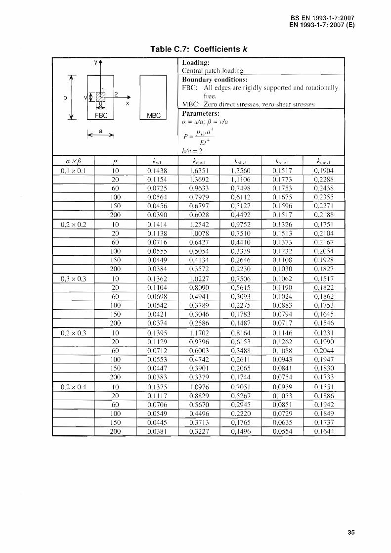
Table C.7: Coefficients k
Loading: Central patch loading
Boundary conditions: FBC: All edges are rigidly supported and rotationally
free . MBC: Zero direct stresses, zero shear stresses
MBC Parameters: ex = ulo; fJ pia
.:l-
p = PF"O Et+
bla = 2
kwl k abxl k abvl kalll;(1 kJIllvl
0,1438 1,6351 1,3560 0.1517 0.1904 0,1154 1,3692 1,1106 0,1773 0,2288 0,0725 0.9633 0,7498 0.1753 02438 0,0564 0.7979 0,6112 0,1675 0,2355 0,0456 0,6797 0,5127 0,1596 0.227 J
0,0390 0,6028 0,4492 0.1517 0,2188
0,1414 1,2542 0.9752 0,1326 0,1751 0,1138 1,0078 0.7510 0,1513 0,2104 0,0716 0,6427 0,4410 0,1373 0.2167 0,0555 0,5054 0,3339 0,1232 0,2054 0,0449 0,4134 0,2646 0.1108 0,1928 0,0384
I
0,3572 I 0,2230 0,1030 0,1827
I 0,1362 1,0227 0,7506 0,1062 0,1517 0,1104 0,8090 0,5615 0,1190 0,1822 0,0698 0,4941 0,3093 0,1024 0,1862 0,0542 0,3789 0.2275 0,0883 0.1753 0,0421 0,3046 0,1783 0,0794 0,1645 0,0374 02586 0,1487 0,0717 0,1546
0,1395 1,1702 0.8164 0,1146 0,1231 0,1129 0,9396 0.6153 0,1262 0,1990 0,0712 0,6003 0,3488 0,1088 0,2044 0,0553 0,4742 02611 0,0943 0,1947 0,0447 0,3901 0.2065 0,0841 0,1830 0,0383 0,3379 0,1744 0,0754 0,1733
0,1375 1,0976 0,7051 0,0959 0,1551 0,1117 0,8829 0,5267 0,1053 0,1886 0,0706 0,5670 0.2945 0,085] 0,1942 0,0549 0,4496 0,2220 0,0729 0,1849 0,0445 0,3713 0,1765 0,0635 0,1737 0,0381 0,3227 0,1496 0,0554 0,1644
35

as EN 1993-1-7:2007 EN 1993-1-7: 2007 (E)
ya
-:r-)r-
b v[;::t~ ~
,~ FBC -~
1< a
a xfJ 0,1 x 0,1
0,2 x 0,2
0,3 x 0,3
0,2 x 0,3
0,2 x 0,4
36
2 .. ... x
>1
p
10 20 60
10 20 60
10 20 60
10 20 60
10 20 60
Table C.B: Coefficients k
Loading: Central patch loading Boundary conditions: FBC: Al1 edges are rigidly suppoI1ed and rotationally
free . MBC: Zero direct stresses, zero shear stresses
MBC n.
did lIt lC~,
a= ula; fJ = via
p = P/~d E 4 ( t
bla = 2.5
kwl kcrhx1 k,:Jbvl kcrlllXI kcrJ1lVI
0,1496 1,6636 1,3463 0,1552 0,1826 0,1235 1,4109 1,1006 0,1811 0,2175 0,0861 1,0428 0,7453 0,1811 0,2374
0,1470 1,2814 0,9650 0,1359 0,1688 0,1218 1,0491 0,7400 0,1548 0,2000 0,0849 0,7205 0,4363 0,1390 0,2088
0,1419 1.0504 0,7410 0.1092 0,1443 0,1182 0,8489 0,5519 0,1222 0,1726 0,0827 0,5681 0,3052 0,1014 0,1775
0,1455 1,1981 0,8056 0,1161 0,1579 0,1210 0,9820 0,6053 0,1294 0,1876 0,0847 0,6806 0,3487 0,1088 0,1982
0,1434 0,1126 0,6949 0,0986 0,1469 0,1199 0,9261 0,5168 0,1069 0,1763 0,0844 0,6480 0,2993 0,0849 0,1873

blank