EN 1993-1-10: Eurocode 3: Design of steel structures ... · PDF fileBS EN 1993-1-10:2005 EN...
19
EN 1993-1-10 (2005) (English): Eurocode 3: Design of steel structures - Part 1-10: Material toughness and through-thickness properties [Authority: The European Union Per Regulation 305/2011, Directive 98/34/EC, Directive 2004/18/EC]
Transcript of EN 1993-1-10: Eurocode 3: Design of steel structures ... · PDF fileBS EN 1993-1-10:2005 EN...

The European Union
In order to promote public education and public safety, equal justice for all, a better informed citizenry, the rule of law, world trade and world peace, this legal document is hereby made available on a noncommercial basis, as it is the right of all humans to know and speak the laws that govern them.
≠ EDICT OF GOVERNMENT ±
EN 1993-1-10 (2005) (English): Eurocode 3: Design of steelstructures - Part 1-10: Material toughness andthrough-thickness properties [Authority: The European UnionPer Regulation 305/2011, Directive 98/34/EC, Directive2004/18/EC]


EUROPEAN STANDARD
NORME EUROPEENNE
EUROpAISCHE NORM
ICS 91.010.30
English version
EN 1993-1-10
May 2005
Supersedes ENV 1993-1-1: 1992 Incorporating Corrigenda December 2005
and March 2009
Eurocode 3: Design of steel structures - Part 1-10: Material toughness and through-thickness properties
Eurocode 3 - Calcul des structures en acier vis-a-vis de la tenacite et des
Partie dans Ie sens de I'epaisseur -
. Choix des qualites d'acier
Eurocode 3: Bemessung und Konstruktion von Stahlbauten - Teil 1-10 :Stahlsortenauswahl im Hinblick auf
Bruchzahigkeit und Eigenschaften in Dickenrichtung
This European Standard was approved by CEN on 20 June 2003.
CEN members are bound to comply with the CEN/CENELEC Internal Regulations which stipUlate the conditions for giving this European Standard the status of a national standard without any alteration. Up-to-date lists and bibliographical references concerning such national standards may be obtained on application to the Management Centre or to any CEN member.
This European Standard exists in three official versions (English, French, German). A version in any other language made by translation under the responsibility of a CEN member into its own language and notified to the Management Centre has the same status as the official versions.
CEN members are the national standards bodies of Austria, Belgium, Cyprus, Czech Republic, Denmark, Estonia, Finland, France, Germany, Greece, Hungary, Iceland, Ireland, Italy, Latvia, Lithuania, Luxembourg, Malta, Netherlands, Norway, Poland, Portugal, Slovakia, Slovenia, Spain, Sweden, Switzerland and United Kingdom.
EUROPEAN COMMITTEE FOR STANDARDIZATION COMITE EUROPEEN DE NORMALISATION EUROPi\ISCHES KOMITEE FOR NORM UNG
Management Centre: rue de stassart, 36 B-1050 Brussels
© 2005 CEN All rights of exploitation in any form and by any means reserved worldwide for CEN national Members.
Ref. No. EN 1993-1-10:2005: E

BS EN 1993-1-10:2005 EN 1993-1-10:2005/AC
Contents Page
General ..................................................................................................................................................... 6
1.1 Scope ................................................................................................................................................. 6 1.2 Nornlative references ......................................................................................................................... 6 ] .3 T erlTIS and definitions ........................................................................................................................ 6 ].4 SYl11bols ............................................................................................................................................. 8
2 Selection of materials for fracture toughness ........................................................................................ 8
2.1 General .............................................................................................................................................. 8 2.2 Procedure ........................................................................................................................................... 8 2.3 Maxi mum permitted thickness values .............................................................................................. 10 2.4 Evaluation using fracture mechanics ................................................................................................ 12
3 Selection of materials for through-thickness properties ..................................................................... 13
3.1 General ............................................................................................................................................. 13 3.2 Procedure .......................................................................................................................................... 14
2

BS EN 1993-1-10:2005 EN 1993-1-1 0:2005/AC
Foreword
This Europcan Standard EN 1993, Eurocodc 3: of steel structures, has been prcpared by Technical Committcc CEN/TC250 « Structural Eurocodes ». the Secretariat of which is held by BSL CEN/TC2S0 is responsible for all Structural Eurocodes.
This European Standard shall be given the status of a National Standard, either by publication of an identical text or by endorscment, at the latest by November 2005, and National Standards shall be withdrawn at latest by March 2010.
This Eurocode supersedes ENV 1993-1-1.
According to the CEN-CENELEC Intcrnal Regulations, the National Standard Organizations of the following countries are bound to implement these European Standard: Austria, Belgium, Cyprus, Czech Republic, Denmark, Estonia, Finland, France, Germany, Greece, Hungary, fceland, Ireland, Italy, Lithuania, Luxembourg, Malta, Netherlands, Nonvay, Poland, Portugal, Slovenia, Spain, Sweden, Switzerland and United Kingdom.
Background to the Eurocode programme
In 1975, the Commission of the European Community decided on an action programme in the tleld of construction, based on article 95 of the Treaty. The objective of the programme was the elimination of technical obstacles to trade and the harmonization of technical specifications.
Within this action programme. the Commission took the initiative to establish a set of harmonized technical rules for the of construction works which, in a first would serve as an alternative to the national rules in force in the l\1ember States and, ultimately, would replace them.
For fifteen years, the Commission, \vith the help of a Committee with Representatives of Member States, conducted the development of the Eurocodes programme, which led to the first generation of European codes in the 1980s.
In 1989, the Commission and the Member States of the EU and EFT A decided, on the basis of an agreemene between the Commission and CEN, to transfer the preparation and the publication of the Eurocodes to CEN through a series of Mandates, in order to provide them with a future status of European Standard (EN). This links de facto the Eurocodes with thc provisions of all the Council's Directives andlor Commission's Decisions dealing with European standards (e.g. the Council Directive 8911 06/EEC on construction products - CPD - and Council Directives 92/50/EEC and 89/440lEEC on public works and services and equivalent EFTA Directives initiated in pursuit of setting up the internal market).
The Stluetural Eurocode programme comprises the following standards generally consisting of a number of Parts:
EN 1990 EN 1991 EN 1992 EN 1993 EN 1994 EN 1995 EN 1996 EN 1997 EN 1998 EN 1999
Eurocode 0: Eurocode 1: Eurocode 2: Eurocode 3: Eurocode 4: Eurocode 5: Eurocode 6: Eurocode 7: Eurocode 8: Eurocode 9:
Basis of Structural Design Actions on structures Design of concrete structures Design of steel structures
of composite steel and concrete structures of timber structures
Design of masol1lY structures Geotechnical design Design of structures for earthquake resistance Design of aluminium structures
1 Agreement between the Commission of the European Communities and the European Committee for Standardisation (CEN) concerning the work on EUROCODES for the design of building and civil engineering works (BC/CEN/03/89).
3

BS EN 1993-1-10:2005 EN 1993-1-1 0:2005/AC
Eurocode standards recognize the responsibility of regulatory authorities in each Member State and have safeguarded their to determine values related to regulatory safety matters at national level where these continue to vary from State to State.
Status and field of application of Eurocodes
The Member States of the EU and EFT A recognize that Eurocodes serve as reference documents for the following purposes:
as a means to prove compliance of building and civil engineering works with the essential requirements of Council Directive 8911 06/EEC, particularly Essential Requirement N° 1 -Mechanical resistance and
- and Essential Requirement N°2 in case of fire;
as a basis for specifying contracts for construction works and related engineering services;
as a framework for drawing up harmonized technical specifications for construction products and ETAs)
The Eurocodcs, as far as they concern the construction works themselves, have a direct relationship with the Interpretative Documel1ts~ referred to in Article 12 of the CPO, although they arc of a different nature from harmonized product standards3
. Therefore, technical aspects arising from the Eurocodes work need to be adequately considered by CEN Technical Committees and/or EOTA Working Groups working on product standards with a view to achieving full compatibility of these technical specifications with the Eurocodes.
The Eurocodc standards provide common structural design rules for cveryday use for the dcsign of whole structures and component products of both a traditional and an innovative nature. Unusual forms of construction or conditions are not specifically covered and additional expert consideration will be required by the in such cascs.
National Standards implementing Eurocodes
The National Standards implementing Eurocodes wiH comprise the full text of the Eurocode (including any annexes), as published by CEN, which may be preccded a National title page and National foreword, and may be followed by a National annex.
The National annex may only contain information on those parameters which are left open in the Eurocode for national choice, knO\\1n as Nationally Determined Parameters, to be used for the design of buildings and civil enginecring works to be constructed in the country concerned, i.e. :
valucs and/or classes where alternatives are given in the Euroeode, values to be used where a symbol only is given in the Eurocode, country data (geographical, climatic, etc.), e.g. snow map,
the procedure to be used where alternative procedures are in the Eurocode. It may contain
decisions on the application of informative annexes, - refcrences to non-contradictory complementary information to assist the user to apply the Eurocode.
2 According to Art. 33 of the CPD, the essential requirements (ERs) shall be given concrete form in interpretative documents for the creation of the necessary links between the essential requirements and the mandates for harmonized ENs and ETAGs/ETAs.
According to Art. 12 Oflhc CPD the interpretative documents shall : a) give concrete form to the essential rcquil'e11lents by harmonizing the terminology and the technical bases and indicating classes or levels for each
b) ('[\r"',A"',i inn Illese classes or levels of requirement with the techniciJl specifications, methods of calculation 8nd of proof, etc. :
c) serve as n eSI[ll)ll:slmlcnt or harmonized standard.., and guidelines for European lechnicnl approvals.
The Eurocodcs, deli/c/o, playa similar role in the fleld of the ER I and part of ER 2.
4
BS EN 1993-1-10:2005 EN 1993-1-10:2005/AC
Links between Eurocodes and harmonized technical specifications (ENs and ETAs) for products
There is a need for consistency between the harmonized technical specifications for constmction products and the technical mles for . Furthelmore, all the information accompanying the CE Marking of the construction products, which refer to Eurocodes, should clearly mention which Nationally Determined Parameters have bcen taken into account.
National annex for EN 1993-1-10
This standard gives alternative procedures, values and recommendations with notes indicating where national choices may have to be madc. The National Standard implementing EN 1993-1-10 should have a National Annex containing all Nationally Determined Parameters for the of steel structures to be constructed in the relevant country.
National choice is allowed in EN 1993-1-10 through clauses:
2.2(5)
3.1(1)
4 see Art.3.3 <lnd Art.12 of tile CPD, as well clauses 4.2,4.3.1,4.3.2 <lnd 5.2 of ID 1.
5

BS EN 1993-1-10:2005 EN 1993-1-10:2005/AC
1 General
1.1 Scope
(1) EN 1993-1-10 contains design guidance for the selection of steel for fracture toughness and for through thickness properties of welded elements where there is a significant risk of lamellar tearing during fabrication.
(2) Section 2 applies to steel grades S 235 to S 690. However section 3 applies to steel grades S 235 to S 460 only.
NOTE EN 1993-1-1 is restricted to steels S235 to S460.
(3) The rules and guidance given in section 2 and 3 assume that the construction will be executed in accordance with EN 1090.
1.2 Normative references
(l) This European Standard incorporates by dated and undated reference provisions from other publications. These normative references are cited at the appropriate places in the text and the publications arc listed hereafter. For dated references, subsequent amendments to or revisions of any of these publications apply to this European Standard only when incorporated in it by amendment or revision. For undated references the latest edition of the publication referred to applies (including amendments).
NOTE The Eurocodcs were published as European Prestandards. The following European Standards which are published or in preparation are cited in normative clauses:
EN 1011-2 \Velding. Recommendations for welding of metallic materials: Part 2: Arc welding of fen'itic steels
EN 1090 Execution of steel structures
EN 1990 Basis of structural design
EN 1991 Actions on structures
EN 1998 Design provisions for earthquake resistance of structures
EN 1 0002 Tensile testing of metallic materials
EN 10025 Hot rolled products of structural steels
EN 10045-1 Metallic materials - Charpy impact test - Part 1: Test method
~ text deleted @il
EN 10160 Ultrasonic testing of steel flat product of thickness equal or greater than 6 mm (reflection method)
EN 10 J 64 Steel products with improved deformation properties perpendicular to the surface of the product - Technical delivery conditions
EN 10210-1 Hot tinished structural hollow sections of non-alloy and fine grain structural steels Part 1: Technical delivery requirements
EN 10219-1 Cold formed welded structural hollow sections of non-alloy and fine grain steels Part 1: Technical delivery requirements
1.3 Terms and definitions
1.3.1 ~ KV·value @il
6

BS EN 1993-1-10:2005 EN 1993-1-10:2005/AC
[lli) The KV (Charpy V-Notch)-value is the impact energy text deleted @2] in Joules [.I] required to fracture a Charpy V -notch specimen at a given test temperature T. Steel product standards generally specify that test specimens should not fail at an impact energy lower than 27J at a specified test temperature T.
1.3.2 Transition region The region of the toughness-temperature diagram showing the relationship ~ KV(T) @2] in which thc material toughness decreases with the decrease in temperature and the failure mode changes from ductile to brittle. The temperature values T 27.1 required in the product standards arc located in the lovv'cr part of this
1.3.3 Upper shelf region The region of the toughness-temperature diagram in which steel clements exhibit elastic-plastic behaviour with ductile modes of failure irrespective of the presence of small flaws and welding discontinuities from fabrication.
~ KV(T) @2] [J]
3
27 J 1 lO'yFer shell region
transition T27J upper
Figure 1.1: Relationship between impact energy and temperature
1.3.4 T 27J
Temperature at which a minimum energyl§)KV@l]willnot be less than 27J in a Charpy V-notch impact test.
1.3.5 Z-value The transverse reduction of area in a tensile test (see EN 10002) of the through-thickness ductility of a specimen, measured as a percentage.
1.3.6 Klc-value The plane strain fracture toughness for linear elastic behaviour measured in
NOTE The two intemationally recognized alternative units for the stress intensity factor K are N/mm3/2 and MPa"m (ie MN/m3/2) where 1 N/mm3
!2 0,032 MPa"m.
1.3.7 Degree of cold forming Permanent strain from cold forming measured as a percentage.
7
BS EN 1993-1-10:2005 EN 1993-1-1 0:2005/AC
1.4 Symbols
lEV KV(T) @2l impact energy in Joule [J] in a test at temperature T with Charpy V notch specimen
~ K stress intensity factor @1)
Z Z-quality
T temperature rOC]
TEd reference temperature
o crack tip opening displacement (CTOD) in mm measured on a small specimen to establish its elastic plastic fracture toughness
J elastic plastic fracture toughness value (J-integral value) in N/mm determined as a line or surface integral that encloses the crack front from one crack surface to the other
K)(: plane strain fracture toughness for linear elastic behaviour measured in N/mmJ/1@2l
ScI' degree of cold forming (DCF) in percent
(JEd stresses accompanying the reference temperature TEd
2 Selection of materials for fracture toughness
2.1 General
(\) The guidance given in section 2 should be used for the selection of material for new construction. It is not intended to cover the assessment of materials in service. The rules should be used to select a suitable gradc of steel from the European Standards for steel products listed in EN 1993-1-1.
(2) The rules are applicable to tension elements, welded and fatigue stressed elements in which some portion of the stress cyclc is tensile.
NOTE For elements not subject to tension, welding or fatigue the rules can be conservative. In such cases evaluation using fracture mechanics may be appropriate, see 2.4. Fracture toughness need not be specified for clements only in compression.
~(3)P The rules shall be applied to the properties of materials specified for the toughness quality in the relevant steel product srandard. Material of a less onerOllS grade shall not to be used even though test results show compliance with the specified grade. ~
2.2 Procedure
(I) The steel grade should be selected taking account of the following:
(i) steel material properties:
yield strength depcnding on the material thickness fit)
toughness quality expressed in terms of TDJ or TIOJ
(ii) member characteristics:
member shape and detail
stress concentrations according to the details in EN 1993-1-9
element thickness (t)
appropriate assumptions for fabrication flaws (e.g. as through-thickness cracks or as semi-elliptical surface cracks)
(iii) design situations:
8
design value of lowest member temperature
maximum stresses from permanent and imposed actions derived from the design condition described in (4) below

BS EN 1993-1-10:2005 EN 1993-1-1 0:2005/AC
residual stress
assumptions for crack from fatigue loading during an inspection interval (if relevant)
strain rate £ from accidental actions (if relevant)
degree of cold forming (Ed) (if relevant)
(2) The permitted thickness of steel clements for fracture should be obtained from section 2.3 and Table 2.1.
(3) Alternative methods may be used to determine the toughness requirement as follO\vs:
fracture mechanics method:
In this method the toughness property.
Numerical evaluation:
value of the toughness requirement should not exceed the design value of the
This may be carried out using one or more test specimens. To achieve realistic results, the models should be constructed and loaded in a similar \vay to the actual structure.
(4) The following design condition should be used:
(i) Actions should be appropriate to the following combination:
I)
where the leading action A is the reference temperature TEd that influences the toughness of material of the member considered and also lead to stress from restraint of movement. IG K are the permanent actions, and \jfl QKI is the frequent value of the variable load and \jf2i QKi are the quasi-permanent values of the accompanying variable loads, that govern the level of stresses on the materiaL
(ii) The combinations factor ~'I and \1'2 should be in accordance with EN 1990.
(iii) The maximum applied stress (jEd should be the nominal stress at the location of the fracture initiation. (jEd should be calculated as for the serviceability limit state taking il1to account all combinations of permanent and variable actions as defined in the appropriate part of EN 1991.
NOTE 1 The above combination is considered to be equivalent to an accidental combination, because of the assumption of simultaneous occurrence of lowest temperature, ±law size, location of -naw and material property.
NOTE 2 (jEd may include stresses from restraint of movement from temperature change.
NOTE 3 As the leading action is the reference temperature TEd the maximum applied stress (jEd
generally will not exceed 75% of the yield stn~l1!..!tI1.
(5) The reference temperature TEd at the potential fracture location should be determined llsing the following expression:
where TmcJ is the lowest air temperature with a specified return period, sec EN ] 991-1-5
~Tr is an adjustment for radiation loss, sec EN 1991-1-5
~ T G is the adjustment for stress and yield strength of material, crack imperfection and member shape and dimensions, sec 2.4(3)
is a safety allO\vance, if required, to reflect different reliability levcls for different applications
~ T £ is the adjustment for a strain rate other than the reference strain rate (sec equation 2.3)
9

BS EN 1993-1-10:2005 EN 1993-1-10:2005/AC
~ T. is the adjustment for the (-'..:1
of cold forming (see equation 2.4)
NOTE J The safety clement to adjust Tid to other reliability requirements may be given in the National Annex. ,6,11<. = 0 °C 1S recommended, when using the tabulated values according to 2.3.
NOTE 2 In preparing the tabulated values in 2.3 a standard curve has been llsed for the temperature shift that envelopes the design values of the stress intensity factor function [K] from applied stresses (JEd and residual stresses and includes the \Vallin-Sanz-eorrelation between the stress intensity factor function [K] and the temperature 1. A value of ~ T (J = DOC may be assumed whell using the tabulated values according to 2.3.
NOTE 3 The National Annex may maximum values of the range between TEd and the test temperature and also the range of (jEd, to which the validity of values for permissible thicknesses in Table 2.1 may be restricted.
NOTE 4 The application of Table 2.1 may be limited in the National Annex to use of up to S 460 steels.
(6) The reference stresses (JEd should be determined llsing an clastic analysis taking into account secondary effects from deformations
2.3 Maximum permitted thickness values
2.3.1 General
(1) Table 2.1 gives the maximum permissible element thickness appropriate to a steel grade, its toughness quality in terms of K V -va lue @lI , the reference stress level [(JEd] and the reference temperature
(2) The tabulated values arc based on the following assumptions:
10
the values satisfy the reliability requirements of EN 1990 for the general quality of material
a reference strain rate £0 4x has been used. This covers the dynamic action cffects for most
transient and persistent design situations. For othcr strain rates i: for impact loads) the tabulated
values may be used by reducing TEd by dcducting given by
1440 - (t ) ( E J 1.5 = - x In- [OC]
550 Eo (2.3)
non cold-formed material with £<.:1' 0% has been assumed. To allow for cold forming of non-ageing
stcels, the tabulated values may be used by adjusting TEd by deducting ~ TEet where
~Tf' 3 Cd [OC] (2.4) '(I
the nominal notch toughness values in terms of are based on the following product standards: EN I 0025, ~ text deleted EN ] 0210-1, EN 10219-1
For other values the following correlation has been used
T40 .! Tn.! + 10 [OC] (2.5)
for members subjcct to fatigue all detail categories for nominal stresses in EN 1993-1-9 are covered
NOTE has been taken into account by applying a fatigue load to a member with an assumed initial flaw The damage assumed is one quarter of the full fatigue damage obtained from EN 1993-1-9. This approach permits the evaluation of a minimum number of "safe periods" between in-service inspections when inspections should be specified for damagc tolerance according to EN

BS EN 1993-1-10:2005 EN 1993-1-10:2005/AC
1993-1-9. The required number [n] of in-service inspections is related to the partial factors YFf and YMr applied in fatigue design according to EN 1993-1-9 by the expression
4 11 = -1
(y ff Y Mf )lll ' where m 5 applies for long life structures such as bridges.
The "safe period" between in-service inspections may also cover the full design life of a structure.
2.3.2 Determination of maximum permissible values of element thickness
(1) Table 2.1 gives the maximum permissible values of element thickness in terms of three stress levels expressed as proportions of the nominal yield strength:
a) (JEd = 0,75 fit) [N/mm2]
b) (JEd = 0,50 fit) [N/mm2] (2.6)
c) (JEd = 0,25 fit) [N/mm2]
where fit) may be determined either from
to
where t is the thickness of the plate in mm
to = 1 mm
or taken as Rewvalues from the relevant steel standards ..
The tabulated values are given in terms ofa choice of seven reference temperatures: 10,0, -10, -20, -30, -40 and -50°C.
11

BS EN 1993-1-10 :2005 EN 1993-1-10:2005/AC
Table 2.1: Maximum permissible values of element thickness t in mm
Reference ''''.'l'f.''''' Cl T, [~C]
Steel Sub- EE2)KV@2] 10 1 0 1-10 1-20 1-30 1-40 I-50 10 I 0 1-10 -20 -30 -40 -50 10 I 0 1-10 1-20 1-30 1-40 I-50
grade grade atT [DC] Jnlin = 0,75 fy(t) ()Ed = 0,50 fy(t) ()Ed 0,25 fy(t)
S235 JR 20 27 60 50 40 35 30 25 20 90 75 65 55 I 45 40 35 135 115 i 100 85 75 65 60 JO 0 27 90 75 60 50 40 35 30 125 105 90 75 65 55 45 175 155 135 115 100 85 75 J2 -20 27 125 105 90 75 I 60 50 40 170 145 125 105 90 75 65 200 200 175 155 i 135 115 100
S275 JR 20 27 55 45 . 35 30 25 20 15 80 I 55 50 40 1 35 30 125 110 95 80 70 60 55 JO 0 1 27 75 65 55 45 35 30 25 115 80 70 55 50 40 165 145 125 110 95 80 70 J2 -20 27 110 95 I 75 65 • 55 45 i 35 155 115 95 80 70 55 200 190 165 145 125 110 95
M,N -20 40 135 110 95 75 i 65 I 55 45 180 155 130 115 95 80 70 200 200 190 165 145 125 110 i ML,NL -50 27 185 160 135 110 95 75 65 200 200 180 155 130 115 95 230 200 200 200 190 165 145
S355 JR 20 27 40 35 25 20 15 15 10 65 55 45 40 30 25 25 110 95 80 70 60 55 45 JO 0 27 60 50 40 35 i 25 20 • 15 95 80 65 55 45 40 30 150, 130 110 95 80 70 60 J2 -20 27 90 75 60 50 40 i 35 25 135 110 1 95 80 65 55 45 200 175 150 130 110 95 80
K2,M,i\1 -20 40 110 90 75 60 • 50 40 35 155 135 110 95 80 65 I 55 200 200 175 150 130 110 95 ML,NL -50 27 155 130 110 90 75 60 1 50 200 180 155 135 110 95 80 210 200 200 200 175 150 130
S420 M,N -20 40 95 80 65 55 45 35 30 140 120 100 85 70 60 50 200 185 160 140 120 100 85 ML,NL -50 27 135 115 95 80 65 55 45 190 165 140 120 100 85 70 200 200 200 185 160 140 120
S460 0 -20 30 70 60 50 40 30 25 20 110 95 75 65 55 45 35 175 155 130 115 95 80 70 M,N -20 40 90 70 60 50 i 40 30 25 130 110 95 75 65 55 45 200 175 155 130 115 95 80 OL -40 30 105 1 70 60 50 40 30 155 130 110 95 75 65 1 55 200 200 175 155 130 115 95
ML,NL -50 27 125 90 70 ! 60 50 40 180 1155 130 110 95 75 65 200 200 200 175 155 130 115 OL1 -60 30 150 125 105 90 70 60 50 200 180 155 130 110 95 75 215 200 200 200 175 155 130
S690 i 0 0 40 40 30 25 20 15 10 10 65 55 45 35 30 20 20 120 1 100 85 75 60 50 45 0 -20 I 30 50 40 30 25 20 15 10 80 65 55 45 35 30 20 140 120 100 85 75 60 50
OL -20 40 60H§i40' 30 I 25 20 . 15 95 80 65 55 45 35 30 165' 140 120 100 85 75 60 OL -40 30 75 50 40 30 25 20 1151 95 80 65 55 45 35 190 165 140 120 100 85 75
OL1 -40 40 90 75 60 50 1 40 30 25 1351115 95 80 65 55 45 200 190 165 140 120 100 85 OL1 -60 30 110 90 75 60 I 50 40 30 160 135 1115 95 80 65 55 200 200 190 165 140 120 100
NOTE I Linear interpolation ean be used in applying Table 2.1. Nlost applications require (JEd values between (JEd 0,75 fit) and (JEd 0,50 f~.(t). = 0,25 t~r(t) is given for interpolation purposes. Extrapolations beyond the extreme values are not valid.
NOTE 2 For ordering products made of S 690 steels, the test temperaturelEVT Kv@1]should be given.
NOTE 3 Table 2.1 has been derived for the guaranteed lEV K V -va lues rolling of the product.
in the direction of the
2.4 Evaluation using fracture mechanics
(1) For numerical evaluation using fracture mechanics the toughness requirement and the design toughness property of the materials may be expressed in terms of CTOD values, J-integral values, K1c values, or lEV KV -values and comparison should be made using suitable fracture mechanics methods.
(2) The following condition for the reference temperature should be met:
TEd 2TRd ~ (2.7)
where TRd is the temperature at \:vhich a safe level of fracture toughness can be relied upon under the conditions being evaluated
The potential failure mechanism should be modelled using a suitable tlaw that reduces the net section of the material thus making it more susceptible to failure by fracture of the reduced section. The flaw should meet the following requirements:
12
location and the shape should be appropriate for the notch case considered. The fatigue classification tables in EN 1993-1-9 may be used for guidance on appropriate crack positions.
for members not susceptible to fatigue the size of the flaw should be the maximum likely to have been left uncorrected in inspections carried out to EN 1 090. ~ The assumed flaw should be located at the position of the 1110S t adverse stress concentration. @1]
BS EN 1993-1-10:2005 EN 1993-1-10 :2005/AC
for members susceptible to fatigue the size of the flaw should consist of an initial flaw grown f~1tigue.
The size of the initial crack should be chosen such that it represents the minimum value detectable by the inspection methods llsed in accordance with EN 1090. The crack growth from should bc calculated with an appropriate fracture mechanics model using loads experienced during the design safe working life or an inspection interval (as relevant).
(4) If a structural detail cannot be allocated a specific detail category from EN 1993-1-9 or if more rigorous methods are used to obtain results which arc more refined than those given in Table 2.1 then a specific verification should be carried out using actual fracture tests on large scale test specimens.
NOTE The numerical evaluation of thc test results may be undertaken using the mcthodology given in Annex D of EN 1990.
3 Selection of materials for through-thickness properties
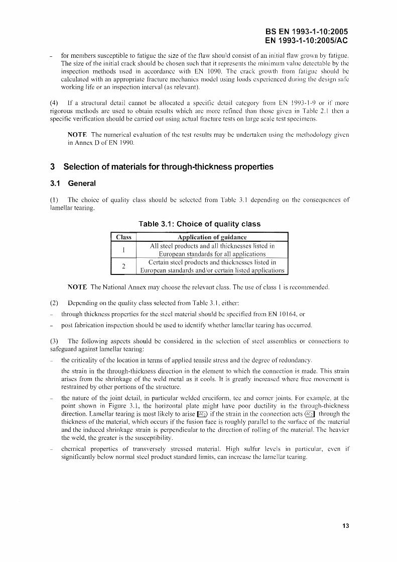
3.1 General
(1) The choice of quality class should be selected from Table 3.1 depending on the conseqllcnces of lamellar tearing.
Table 3.1: Choice of quality class
Class Application of guidance
1 All steel products and all thicknesses listed in
European standards for all applications
2 Certain steel products and thicknesses listed in
European standards and/or certain listed applications
NOTE The National Annex may choose the relevant class. The use of class I is recommended.
(2) Depending on the quality class selected from Table 3.1, either:
through thickness properties for the steel material should be specified from EN 10 164, or
post fabrication inspection should be used to identify whether lamellar tearing has occurred.
(3) The following aspects should be considered in the selection of steel assemblics or connections to safeguard against lamellar tearing:
the criticality of the location in terms of applied tensile stress and the degree of redundancy.
the strain in the through-thickness direction in the element to which the connection is made. This strain arises from the shrinkage of the weld metal as it cools. It is greatly increased where t1:ce movement is restrained by other portions of the structure.
the nature of the joint detail, in particular wclded cruciform, tee and corner joints. For example, at the point shown in Figurc 3.1, the horizontal plate might have poor ductility in the through-thickness direction. Lamellar tearing is most likcly to arise if the strain in the connection acts @1] through the thickness of the material, which occurs jf tbe fusion face is roughly paralIc] to the surface of the material and the induced shrinkage strain is perpendicular to the direction of rolling of the material. The heavier the weld, the greater is the susceptibility.
chemical properties of transversely stressed material. High sulfur levels in particular, even if significantly below normal steel product standard limits, can increase the lamellar tearing.
13

BS EN 1993-1-10:2005 EN 1993-1·10:2005/AC
Figure 3.1: Lamellar tearing
(4) The susceptibility of the material should be determined by measuring the through-thiclmess ductility qual ity to EN 10164, which is expressed in terms of quality classes identified by Z-values.
NOTE] Lamellar tearing is a weld induced flaw in the material which generally becomes evident during ultrasonic inspection. The main risk of tearing is with cruciform, T - and corner joints and with full penetration welds.
NOTE 2 Guidance on the avoidance of lamellar tearing during welding is given in EN 1011-2.
3.2 Procedure
(1) Lamellar tearing may be neglected if the following condition is satisfied:
(3.1)
where ZEd is the required design Z-value resulting from the magnitude of strains from restrained metal shrinkage under the weld beads.
ZRd is the available design Z-value for the material according to EN 10164, i.e. Z15, Z25 or Z35.
(2) The required design value ZEd may be determined using:
(3.2)
in which Za, Zc, Zd and are as given in Table 3.2.
14

a)
b)
c)
d)
e)
*
BS EN 1993-1-10:2005 EN 1993-1-10:2005/AC
Table 3.2: Criteria affecting the target value of lEd
Weld depth .1El> Effective weld depth ClefI' IEl> thickness a of fillet wc lds~ Zj relevant for (scc Figure 3.2) @2] straining from aeff :S 7mm a= 5 IllIll Za= 0 metal shrinkage 7 aeff_ 10mm a 7mm Za 3
10 aeff 20mm a l4m111 Za= 6 20 < aeff 30111m a 21 mm Za 9 30 aeff< 40111111 a 28111m Za 12 40 < acff 50111111 a 35 111111 Za 15 50 < aeff a> 35111111 Za 15
Shape and O.7s
position of U Jr n y ~ Zh = -25 welds in T - and ~
cruciform- and I • I
corner-
f conncctions corner joints Zh -]0
single run fillet wclds Za = 0 or fillet JL Jb 6 welds with ] with buttering Zh -5 with low strength weld material I I Is
multi run fillet welds JLffi ~ Zh 0 I I
sequence to reduce shrinkage
~i~-' partial and full O! ~ Zh = 3 penetration welds Is M. partial and full n ~ JL n Zb = 5 penetration welds I I Is I I
corner joints ~ ~ Zh=S
Effect of s 10mm Zc 2" material 10 <s _ 20mm Zc 4'" thickness on 20 < s < 30mm Zc 6':' restraint to 30 <s<40mm Zc S" shrinkage
40 < s:S 50mm Zc 10'
50 <s<60mm Zc = Ii' 60 s:S 70mm Zc = IS"
70 Zc = 15 ~':
s Remote
Low restraint: Free shrinkage possible
Zd = 0 restraint of (e.g. T-joints) shrinkage after
Medium restraint: Free shrinkage restrictcd
~ welding by (e.g. diaphragms in box girders) other portions
High restraint: Free shrinkage not possible
! Z,,=~ of the structure (e.g. stringers in orthotropic deck plates) Influence of Without preheating Zl' 0 preheating Preheating 2: 100°C Z" -S
May be reduced by 50% for material stressed, in the through-thic1GICSS direction, by compression duc to predominantly static loads.
15

BS EN 1993-1-10:2005 EN 1993 .. 1-1 0:2005/AC
Figure 3.2: Effective weld depth aeff for shrinkage
(3) The appropriate ZRd-class according to EN 10164 may be obtained by applying a suitable classification.
NOTE For classification see EN 1993-1-1 and EN 1993-2 to EN 1993-6.
16

1
1
1
1
1
1
1
1
1
1
1
1
1
1
1
1
1
1
1
1
blank
1
1
1
1
1
1
1
1
1
1
1
1
1
1
1
1
1
1
1
1
1


![EN 1993-3-1: Eurocode 3: Design of steel structures - Part ... 3... · EN 1990 Eurocode 0: EN 1991 Ellrocode 1: EN ]992 Eurocode 2: ... EN 1993-3-1 :2006 (E) EN 1998 Eurocode 8: Design](https://static.fdocuments.us/doc/165x107/5a7fd56a7f8b9aa24f8bfb62/en-1993-3-1-eurocode-3-design-of-steel-structures-part-3en-1990-eurocode.jpg)


![EN 1993-1-1: Eurocode 3: Design of steel structures - Part ... · PDF fileEN 1996 Eurocode 6: Design of masonry structures EN ]997 Eurocode 7: Geotechnical design EN 1998 Eurocode](https://static.fdocuments.us/doc/165x107/5a71061f7f8b9aa2538c9518/en-1993-1-1-eurocode-3-design-of-steel-structures-part-nbsppdf.jpg)