EN 1992-1-1 Design
100
Reinforced and Prestressed Concrete Design according to EN 1992-1-1 with National Annexes Austria Germany Great Britain Sweden
Transcript of EN 1992-1-1 Design

Reinforced and PrestressedConcrete Design
according to EN 1992-1-1
with National AnnexesAustria
GermanyGreat Britain
Sweden

The description of program functions within this documentation should not be considered a warranty of product features.All warranty and liability claims arising from the use of this documentation are excluded.
InfoGraph® is a registered trademark of InfoGraph GmbH, Aachen, Germany. The manufacturer and product namesmentioned below are trademarks of their respective owners.
This documentation is copyright protected. Reproduction, duplication, translation or electronic storage of this document orparts thereof is subject to the written permission of InfoGraph GmbH.
InfoGraph® Software, version 21, uses Microsoft® MFC and Intel® MKL Libraries.
© InfoGraph GmbH, Aachen, Germany, October 2021. All rights reserved.
Title image: Structure model of the 180 m high 'Europe Tower' in Sofia, Bulgaria.Courtesy of IDN Ingenieurbüro DOMKE Nachf., Duisburg, Germany.

1
Contents
© InfoGraph GmbH, Aachen, Germany, October 2021
ContentsBasics 3
Input 4Actions and Design Situations 4
Definition of an Action 6
Partial Safety Factors 7
Section Inputs 8
Analysis Settings 19
Single Design 21
Punching Shear Check 22
Prestressed Structures 25Internal Prestressing 25
External Prestressing, Mixed Construction 30
Variation of Prestressing 30
Creep and Shrinkage 31
Relaxation of Prestressing Steel 32
Check Internal Forces 33
Checks in the Ultimate Limit States 35Design Combinations 35
Stress-Strain Curves 36
Design for Bending With or Without Normal Force or Normal Force Only 36
Minimum Reinforcement Against Failure Without Warning 38
Surface Reinforcement 38
Design for Lateral Force 39
Design for Torsion and Combined Stressing 42
Shear Joint Check 44
Punching Shear 45
Checks Against Fatigue 50Design Combinations 50
Stress-Strain Curves 50
Fatigue of Longitudinal Reinforcement, Shear Reinforcement and PrestressingSteel 51
Fatigue of Concrete Under Longitudinal Compressive Stress 52
Fatigue of the Concrete Compressive Struts Under Lateral Force and Torsion 53
Special Characteristic of Shell Structures 54
Checks in the Serviceability Limit States 55Design Combinations 55
Stress-Strain Curves 55
Stress Analysis 55
Limiting the Concrete Compressive Stresses 56
Limiting the Reinforcing and Prestressing Steel Stresses 57
Decompression Check 57
Minimum Reinforcement for Crack Width Limitation 58
Crack Width Calculation 60
Crack Width Check by Limitation of the Bar Distances 62
Determining the Effective Area Ac,eff 63
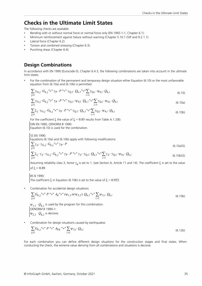
Limiting Deformations 65
Results 66
Examples 68Slab With Downstand Beam 68
Flat Ceiling With Cantilever 74
Flat Ceiling With Cantilever and Prestressing 78
Prestressed Roof Construction 81
Torsional Beam 90

2
Contents
© InfoGraph GmbH, Aachen, Germany, October 2021
Single Design Reinforced Concrete 92
Single Design Prestressed Concrete 93
References 95

3
Basics
© InfoGraph GmbH, Aachen, Germany, October 2021
EN 1992-1-1 Design
BasicsThe reinforced concrete and prestressed concrete design specified in EN 1992-1-1 (Eurocode 2) can be used for buildingsand engineering constructions under observance of the following standards:
• EN 1992-1-1:2004/A1:2014 as the base document
• DIN EN 1992-1-1:2015 with the National Annex Germany 2015-12
• OENORM EN 1992-1-1:2015 with the National Annex Austria B 1992-1-1:2018-01
• SS EN 1992-1-1:2014 with the National Annex Sweden 2019-01 (EKS 11)
• BS EN 1992-1-1:2014 with the National Annex Great Britain 2015-07
The desired rule is selected in the Design Codes dialog in the Options menu. The relevant entry, calculation and resultsdialogs appear depending on which rule is selected. When selecting the material the following alternatives are available:
• C12/15-EN-D to C100/115-EN-D, LC12/13-EN-D to LC80/88-EN-D and the user-defined material CX-EN-D for design inaccordance with DIN EN 1992-1-1
• C12/15-EN to C90/105-EN, LC12/13-EN to LC80/88-EN and the user-defined material CX-EN for design in accordancewith the other standards
Permitted structure models include beam, area and solid structures. Prestressed structures can only be checked in the FEMmodule.
Differing components can be combined in a structure model:
• Non-prestressed components
• Prestressed components with subsequent bond
• Prestressed components without bond
• Components with external prestressing
• Mixed-construction components
The design is carried out after the static calculation. To do so, you need to assign the calculated load cases to the actions inaccordance with EN 1991:2002 (Eurocode 1), Part 1. The program will take into account the preset safety factors andcombination coefficients defined in EN 1990:2021 (Eurocode 0) for the desired design situations to automatically calculatethe decisive design internal forces for either the entire system or a group of selected elements.
The actions and check selection dialogs can be opened from the analysis settings. Detailed check specifications andreinforcement data must be entered during section definition.
For beams and design objects, all checks are carried out at the polygon section. For general notes on using design objects,refer to the relevant chapter in the manual.
In the EN 1992-1-1 Design folder of the database and the national variants folders, a single design can also be performedfor the user-defined polygon sections.
The EN 1992-1-1 guidelines are primarily cited for the following explanations. Reference to the relevant national settings isonly made if they contain different or complementary rules. The passages in question are marked by a vertical line left of thetext.

4
EN 1992-1-1 Design
© InfoGraph GmbH, Aachen, Germany, October 2021
Input
Actions and Design SituationsThe design values of the load are calculated based on the internal forces of individual load cases and load casecombinations. For this the existing load cases and load case combinations must be assigned to actions. These actions arethen used to establish the desired design situations.
The following dialog is opened from the database or the Settings in the Analysis menu.
Action dialog for EN 1992-1-1 (national variants corresponding)
Action...
Open the dialog for entering new actions:
• Permanent actions (G, GE, GH)
• Prestressing (P)
• Creep and shrinkage, relaxation (CSR1, CSR2). These actions are only available if a P action has been defined. In thecombinations they are treated, along with P, as a single action.
• Variable actions (QN, QS, QW, QT, QH, QD)
• Accidental actions (A)
• Actions due to earthquakes (AE)
• Design values of actions (Fd)The assigned load cases should contain a design-relevant set of loads with partial safety factors and combinationcoefficients such as for example a load group to take into account nonlinear effects. The selected load cases arecombined exclusively.
• Cyclic fatigue actions (Qfat)
Group...
Open the dialog for entering a new design group. Open the dialog for entering a new design group. According to e.g.standard EN 1991-1-1, Chapter 6.2.2 (2), certain components (sections) may be designed with reduced imposed loads.Therefore, variable actions (Q) and design situations can be changed here.
Situation...
Open the dialog for entering new design situations. Situations must be classified as either a construction stage or a finalstate in order to control the checking process. For prestressed concrete structures with subsequent bond, you can specifythat the tendons are still ungrouted.
Edit
Open the Edit dialog for the selected action or situation.
Delete
Delete the selected action or situation.

5
Input
© InfoGraph GmbH, Aachen, Germany, October 2021
Combinations...
Opens a dialog that contains the first 999,999 load case variants to be combined for the selected design situation andincludes an option to create load groups for selected variants. These variants can be used for second-order theory analysis ornonlinear analysis.
The following example shows the total variants of the permanent and temporary situation according to Eq. (6.10) to beexamined with the load cases (L1...L6) involved and their weighting factors.
Actions Load cases gsup ginf y0
Dead load 1 1.35 1.0 -
Imposed load, traffic load 2, 3 (inclusive) 1.5 0 0.7
Wind load 4 1.5 0 0.6
Fd Design values of actions 5, 6 1.0 1.0 -
Calculate
Calculate the defined design situations. Once calculated, the extremal results (internal forces, support reactions) can beaccessed for all situations in the database. This allows you to evaluate the results without having to execute the checkingmodule. Each time you execute the checking module, all results will be automatically recalculated using the currently validactions and then stored in the database for the elements to be checked.
Use combination rules of EN 1990 (6.10a/b)
Optionally the Eq. (6.10a/b) are used for the combination of the permanent and temporary situation, otherwise Eq. (6.10).
The following table demonstrates how the situations are used in the various checks. The numbers refer to the Chapters ofthe EN 1992-1-1 standard.

6
EN 1992-1-1 Design
© InfoGraph GmbH, Aachen, Germany, October 2021
Situation Ultimate limit state Chapter Serviceability limit state Chapter Perm. and temp. Accidental Earthquake
Longitudinal reinf. Lateral reinf. Torsional reinf.
6.1 6.2 6.3
Characteristic (rare)
Robustness reinf. (EN 1992-2, 6.1 (110))
9.2.1.1 Concrete compr. stress Reinforcing steel stress Prestressing steel stress Crack width, prestr. with immed. bond
7.2 (2) 7.2 (5) 7.2 (5) 7.3.1DE
Frequent Fatigue, simplified 6.8.6 (2) Decompr. Class XD1-XS3 Crack width, prestr. with bond
7.3.1 7.3.1
Quasi-continuous Concrete compr. stress Prestressing steel stress Decompr. Class XC2-XC4 Crack w., reinf.concr. & prestr. w/o b. Deformations
7.2 (2) 7.2 (5)DE 7.3.1 7.3.1 7.4
Fatigue Fatigue reinf. steel Fatigue prestr. steel Fatigue concrete
6.8.4 6.8.4 6.8.7 (1)
Definition of an ActionThe illustration below shows an example of the dialog field for entering a variable action. The dialog fields for other actiontypes are of a similar appearance.
Name
User-defined label for the action.
Gamma.sup, Gamma.inf
Partial safety factors gsup and ginf. The nationally valid values are suggested based on EN 1990, Table A.1.2(B).
DIN EN 1992-1-1:
In accordance with 2.3.1.3 (4) a partial safety factor for settlements gG,Set = 1.0 can be assumed for the linear-elastic
determination of internal forces with stiffnesses of uncracked sections.
SS EN 1990:
The program suggests the partial safety factors as they result in accordance with Section A, Article 11, for safety class 3
from gd · gsup with the reduction factor gd = 1.0 as per Article 14. If required, lower safety classes can be taken into account
entering lower values.

7
Input
© InfoGraph GmbH, Aachen, Germany, October 2021
Combination coefficients psi for:
Input fields for selecting the combination coefficients for variable actions according to EN 1990. The default number values
are based on the national specifications in Table A.1.1 of the standard. Click the button to view and edit the selected
combination coefficients y0, y1 and y2.
Load cases
List of the possible load cases or load case combinations. Select items by highlighting them and clicking the button oruse drag & drop.
Multi-select
Load cases and combinations can be added to the actions more than once.
Exclusive variants
Variable actions may consist of multiple exclusive variants that are mutually exclusive. The variants themselves contain both
inclusive and exclusive parts. You can add or delete action variants with the or buttons.
Inclusive load cases
Selected load cases and combinations that can have a simultaneous effect.
Exclusive load cases
Selected load cases and combinations that are mutually exclusive.
Prestressing loss from relaxation of prestressing steel
The prestressing loss is defined as a constant percentage reduction of prestress.
CS as constant reduction of prestress
As an alternative to defining CS load cases, you can allow for the effect of creep and shrinkage by defining a constantpercentage reduction of prestress.
Internal prestressing
Selected load cases that describe internal prestressing. The reactions of the individual load cases are added together.
External prestressing
Selected load cases that describe external prestressing. The reactions of the individual load cases are added together.
Partial Safety FactorsThe partial safety factors of the construction materials are preset with the nationally applicable values as specified inEN 1992-1-1, Table 2.1. In the design situations due to earthquakes, the safety factors of the accidental design situationmay be assumed in accordance with EN 1998-1, Chapter 5.2.4 (3), if the strength loss is taken into account whendetermining the material properties. Otherwise, the factors of the permanent and temporary design situation must beapplied in accordance with Chapter 5.2.4 (2).
The partial safety factors for the actions are specified in the definition of the actions based on EN 1990, Table A.1.2(B).
OENORM B 1998-1:
In design situations resulting from earthquakes, the factors for construction materials according to OENORM B 1998-1,Chapter 5.2.4 (3), apply.
DIN EN 1998-1:
In the design situations due to earthquakes, according to the NDP to 5.2.4 (1) and (3), the safety factors of the permanentand temporary design situation generally apply.

8
EN 1992-1-1 Design
© InfoGraph GmbH, Aachen, Germany, October 2021
Section InputsThe section inputs contain all of the specific settings made for checks in the ultimate limit and serviceability states. Inaddition to these specifications, the selected material properties and the properties of the reinforcing steel are also relevantfor the design. An overview of the design specifications can be accessed in the EN 1992-1-1 Design folder of the databaseand in the folders of the national variants.
Checks
The following dialog is used to define which ultimate limit state and serviceability checks are available for the section. Theanalysis settings allow to override this selection for the entire structure.
Check selection for EN 1992-1-1 (national variants corresponding)
Prestressing of the component
The type of prestressing can be selected for each section separately:
• Not prestressed
• Subsequent bond
• Without bond
• External
• Mixed construction
Exposure class
The check conditions for the decompression and crack width check are grouped by exposure class in EN 1992-1-1,Chapter 7.3, Table 7.1N. A component can be assigned to an exposure class based on the information provided in Table 4.1of the standard.
SS EN 1992-1-1:
In addition, the service life class as per Article 10 can be selected to determine the crack width according to Table D-2 andthe crack safety factor according to Table D-3.
Robustness
This check determines the minimum reinforcement against failure without notice (robustness reinforcement) based onEN 1992-1-1, Chapter 5.10.1 (5)P with the method specified for prestressed concrete bridges in EN 1992-2, Chapter6.1 (109), Equation (6.101a). It thus offers an alternative to minimum reinforcement as per EN 1992-1-1, Chapter9.2.1.1 (1), Equation (9.1N). The latter can be taken into account when necessary by specifying a base reinforcement in thereinforcing steel description.
DIN EN 1992-1-1:
According to Chapter 9.2.1.1 (1), the ductile component behavior must always be ensured for components with or withoutprestressing by applying robustness reinforcement.

9
Input
© InfoGraph GmbH, Aachen, Germany, October 2021
Steel tensile stresses
For components with internal prestressing, both the prestressing steel stresses an the stresses of the longitudinalreinforcement are checked.
Minimum crack reinforcement, crack width
The crack width check is carried out according to Chapter 7.3.4. In this check the final longitudinal reinforcement is set asthe maximum value from the bending reinforcement, robustness reinforcement and minimum crack reinforcement as per7.3.2. The latter will be increased automatically if necessary to maintain the crack width.
Base Values
Unless otherwise specified, the base values apply for all checks in the ultimate, fatigue and serviceability limit states.
Design mode
• Standard: Standard design mode for bending with normal force throughout the load area. Reinforcement will becalculated in the tensile section to the greatest degree possible.
• Symmetrical: Design for symmetrical reinforcement. As opposed to the standard mode, all of the reinforcement layerswill be increased if a reinforcement increase is necessary.
• Compression member: For compression members, a symmetrical design is carried out taking into account the minimumreinforcement according to Section 9.5.2 (2).
Factor for as in secondary direction
According to EN 1992-1-1, Section 9.3.1.1 (2), secondary longitudinal reinforcement of one-way slabs should not be lessthan 20% of the principal reinforcement. The examination is carried out on the program side with the results of thebending design separately for the upper and lower side of the cross-section. The direction with the largest amount ofreinforcement per cross-sectional side defines each principal reinforcement direction. The assignment of the factorizedreinforcement in secondary direction then takes place via corresponding reinforcement layers.DIN EN 1992-1-1:
In the case of two-way slabs, the less stressed direction should be reinforced with at least 20% of the higher stresseddirection.
Reduction factor of prestr. for robustness
In the program the regulations of the EN 1992-2, Chapter 6.1 (110) are decisive for the arrangement of the robustnessreinforcement. Thus for the determination of the tensile zone the statically determined effect of prestressing is not takeninto account. Because this cannot be determined for area elements alternatively the prestress can be reduced by a reductionfactor. The specification of an appropriate value is subject to the discretion of the user.
Design without considering given reinforcement ratios
If selected, the reinforcement increase required in the design is performed without taking into account the reinforcementratios specified by the basic reinforcement.

10
EN 1992-1-1 Design
© InfoGraph GmbH, Aachen, Germany, October 2021
Effective height
Effective static height for the shear design of area elements [m].
Angle cot Theta
cot Q defines the concrete strut angle according to Chapter 6.2.3 (2), Equation (6.7N). The program will suggest a value of1 (45° strut angle). You can choose to ignore the suggestion and pick any value within the permissible national limits.Entering a higher number will normally result in a lower necessary lateral force reinforcement Asw, a lower absorbable
lateral force VRd,max and a larger displacement a1 according to Chapter 9.2.1.3, Equation (9.2).
DIN EN 1992-1-1:
Three calculation methods can be chosen for the check:
• Standard: The input value is limited to the range permitted in accordance with Eq. (6.7aDE) for lateral force, torsionand combined loads (method with load-dependent strut angle).
• Constant: The check is carried out using the chosen value for cot Q without further limitations (cf. interpretation No. 24 of NABau for DIN 1045-1).
• Std./45°: For lateral force cot Q is limited according to Eq. (6.7aDE), for torsion a constant strut angle of 45° isassumed for simplification according to Chapter 6.3.2 (2).
The actual effective angle of the concrete struts is logged for each check location.
OENORM B 1992-1-1:
The concrete strut angle is defined by tan Q and should be limited according to equations (3AT) and (4AT).
SS EN 1992-1-1:
According to Article 15 and differing from Equation (6.7N), for prestressed components the condition 1.0 £ cot Q £ 3.0applies.
Asl acc. to Fig. 6.3
The bending tensile reinforcement to be taken into account according to Chapter 6.2.2, Figure 6.3 [cm²].
Asl extension to
You can optionally specify a maximum value for areas and the program will automatically increase the above input valueuntil that maximum value is reached in order to avoid stirrup reinforcement [cm²].
Quality of the stirrups
• 420S: Reinforcing rod with fyk = 420 MN/m².
• 500S: Reinforcing rod with fyk = 500 MN/m².
• 500M: Reinforcing meshes with fyk = 500 MN/m².
• General information: Freely definable steel quality [MN/m²].
Design like slabs
Beams or design objects are treated like slabs, which means that a minimum lateral force reinforcement will not bedetermined as per Chapter 6.2.1 (4), if no lateral force reinforcement is required for computation.
Factor for rho.w,min
The minimum reinforcement level rw,min is defined using a factor related to the standard value for beams according to
EN 1992-1-1, Chapter 9.2.2 (5).
DIN EN 1992-1-1, OENORM B 1992-1-1:For slabs with VEd > VRd,c at least the 0.6-fold value of the minimum shear reinforcement of beams is necessary.
DIN EN 1992-1-1:For structured sections with prestressed tension chord the 1.6-fold value is to be applied according to Equation (9.5bDE).
SS EN 1992-1-1:
If the fire safety class is 1 or 2 and no shear reinforcement is required, rw,min can be set to zero as per Article 26.

11
Input
© InfoGraph GmbH, Aachen, Germany, October 2021
Laying measure cv,l
DIN EN 1992-1-1:
In Chapter 6.2.3 (1) the inner lever arm z is limited to the maximum value derived from z = d – cv,l – 30 mm and z = d – 2cv,l.
Note that cv,l is the laying measure of the longitudinal reinforcement in the concrete compressive zone. For cv,l the program
will suggest the smallest axis distance of the longitudinal reinforcement to the section edge d1.
Separate check for x and y direction
DIN EN 1992-1-1:
For two-axes stressed slabs, the lateral force check can be performed separately in the x and y stress directions as describedin Chapter 6.2.1 (10). The user is responsible for properly aligning the reinforcement directions.
Shear Section
For polygon sections, additional section dimensions are required for the lateral force and torsion design. These are explainedin the following. In case of sections with internal prestressing or with a shape that differs from a rectangle, the dimensionssuggested by the program should be reviewed.
Width
Section width for calculating the lateral force load-bearing capacity for Qz [m].
Height
Section height for calculating the lateral force load-bearing capacity for Qy [m].
Effective height
Effective static height for calculating the lateral force load-bearing capacity for Qz [m].
Effective width
Effective static width for calculating the lateral force load-bearing capacity for Qy [m].
Nominal width, nominal height
The nominal width or height of internally prestressed components as per EN 1992-1-1, Chapter 6.2.3 (6), for including theduct diameter in the calculation of the design value of the lateral load-bearing capacity VRd,max.
Factor kb, Factor kd
Factor for calculating the inner lever arm z from the effective width bn or effective height d in the lateral loadbearing
capacity check for Qy or Qz.

12
EN 1992-1-1 Design
© InfoGraph GmbH, Aachen, Germany, October 2021
Core section Ak = z1 * z2
Dimensions of the core section for calculating the torsion reinforcement [m].
tef
The effective wall thickness of the torsion section according to Figure 6.11 [m].
Box section
Selection of the rules applicable for box sections for the check of the maximum load-bearing capacity according to Chapter6.3.2 (4) and for the required reinforcement according to Chapter 6.3.2 (5) in case of combined stress from lateral force andtorsion.
Shear Joint
The shear joint check is available for polygon cross sections. The input values proposed by the program must be checked bythe user and adjusted if necessary.
Joint location
The program can automatically determine the location of the joint at the transition between the slab and the web.Alternatively, the user can define the distance of the joint from the top edge of the cross-section dz [m].
Joint roughness
The roughness of the joint (very smooth, smooth, rough, indented).
Factor c
Factor for determining the shear resistance in the joint, which is specified depending on the joint roughness according toEN 1992-1-1, Chapter 6.2.5 (2) and can only be adjusted by the user if the joint is very smooth.
Joint width bi
Width of the joint over which shear forces are transferred between existing and new concrete [m].
Stress perpendicular to joint (comp. neg.)
Stress sn caused by the minimum normal force perpendicular to the joint which can act simultaneously with the lateral
force [N/mm²]. Compressive stresses must be entered with a negative sign and are limited in the check according to6.2.5 (1).
Dynamic or fatigue stress according to 6.2.5(5)
If this option is selected, a dynamic or fatigue stress on the cross-section is assumed and the factor c is adjusted accordingto 6.2.5 (5).

13
Input
© InfoGraph GmbH, Aachen, Germany, October 2021
Stresses
perm. sigma.c
The concrete compressive stress sc must be limited to 0.60 fck under the characteristic action combination in the
construction stages and final states according to EN 1992-1-1, Chapter 7.2 (2). If stress in the concrete under quasi-continuous combination does not exceed the limit 0.45·fck, linear creep can be assumed according to 7.2 (3). If this is not
the case, non-linear creep must be taken into account.
perm. sigma.c(t)
Permissible concrete stress sc(t) at time t when prestressing is introduced. If the compressive stress exceeds the value
0.45·fck(t), the nonlinearity of the creep should be taken into account according to the standard. The program assumes that
prestressing is introduced in design situation 'G+P'.
fck(t)
Concrete compressive strength at time t when prestressing is introduced according to Chapter 5.10.2.2 (5) of the standard[MN/m²].
Reinforcing steel stresses
According to Chapter 7.2 (5) the tensile stresses in the reinforcement may not exceed the value 0.8·fyk under the
characteristic action combination. For stresses resulting from indirect action, the limits can be assumed as 1.0·fyk.
SS EN 1992-1-1:
According to Article 19, the limit 1.0·fyk can be generally assumed.
Decompression, check combination
The action combination (AC) for the decompression check normally results from the selected exposition class. Alternatively,a deviating combination can be chosen.

14
EN 1992-1-1 Design
© InfoGraph GmbH, Aachen, Germany, October 2021
Crack Width
These specifications apply to the minimum crack reinforcement calculation and the crack width check.
Section edge
The following properties can be defined differently for the section edges and the reinforcement directions:
wmax limit for the calculated crack [mm].
sr,max largest permissible crack spacing [mm].
kc calculation method for coefficient kc.
max. ds largest existing bar diameter [mm].
max. s largest existing bar spacing [mm].
The following options are available for editing:
Standard The standard properties are used for the unspecified edges and directions.
Top, bottem, x, y Definition for the top or bottom edge in the x or y reinforcement direction.
<Add> Starts the dialog for adding a section edge.
<Delete> Deletes the displayed section edge.
wmax
Limit for the calculated crack width according to EN 1992-1-1, Chapter 7.3.1, Table 7.1N [mm]. The program will suggest atabular value according to the national requirements based on the selected exposure class and the prestressing of thecomponent. This value can be modified after the input field is enabled.
SS EN 1992-1-1:
In addition, the service life class is taken into account to determine the suggested value according to Article 20, Table D-2.For prestressed components the tabular values for higher corrosion are taken, for reinforced concrete the values for slightcorrosion apply.
sr,max
When calculating the crack width, the crack spacing sr,max is determined by default using Equation (7.11) of the standard.
Alternatively, the user can specify an upper limit to take into account any special conditions of Equation (7.14) orSections (4) and (5) of Chapter 7.3.4, for example.
Coefficient kc
The following methods are available for calculating the coefficient kc:
auto For rectangular solid sections, kc is calculated according to Eq. (7.2), in all other cases according to Eq. (7.3).
web kc is calculated according to Eq. (7.2).
chord kc is calculated according to Eq. (7.3).

15
Input
© InfoGraph GmbH, Aachen, Germany, October 2021
max. ds
Largest existing bar diameter of the reinforcing steel reinforcement for evaluating Equations (7.6N), (7.7N) and (7.11) inChapter 7.3 of the standard [mm].
max. s
Largest existing bar spacing of the reinforcement for the simplified crack width check as per Chapter 7.3.3 (2) [mm].
Determ. of the tensile zone
You can specify the tensile section where the minimum crack reinforcement as per Chapter 7.3.2 will be placed by selectingeither an action combination or a restraint (bending, centrical tension).
Thick component
DIN EN 1992-1-1:
Based on DIN EN 1992-1-1, Chapter 7.3.2 (5), the minimum reinforcement for the crack width limitation in the case ofthicker components under centrical restraint can be determined according to Equation (NA 7.5.1). Therewith a reductioncompared to the calculation with Equation (7.1) can be achieved.
Minimum reinforcement according to Eq. (17AT)
OENORM B 1992-1-1:
The minimum reinforcement for the crack width limitation under centrical restraint can be determined according toEquation (17AT). Therewith a reduction compared to the calculation with Equation (7.1) can be achieved.
Coefficient k
Coefficient for taking into account nonlinear distributed concrete tensile stresses in the section in Chapter 7.3.2,
Equation (7.1). Depending on the flange width or the web height h the value k can be assumed between 0.65 (h ³800 mm) and 1.0 (h £ 300 mm).
DIN EN 1992-1-1:
In case of restraint within the component, k can be multiplied by 0.8 whereby the minimum of the height and the width of
the section or section part shall be used for h. For tensile stresses due to restraint generated outside of the component,
k = 1.0 applies.
SS EN 1992-1-1:
Depending of the section dimension h (flange thickness resp. web height), the factor k can be assumed between
0.50 (h ³ 680 mm) and 0.90 (h £ 200 mm) according to Article 4a.
Factor for fctm
This factor is used to specify the effective concrete tensile strength fct,eff based on the average value of tensile strength fctm.
This is done separately for the minimum reinforcement calculation according to Equation (7.1) and the crack widthcalculation according to Equation (7.9) of the standard. The tensile strength, which depends on the age of the concrete, isdefined in Equation (3.4) of Chapter 3.1.2.
DIN EN 1992-1-1:
If it is not certain wether crack formation will occur within the first 28 days, a tensile strength of at least 3.0 MN/m² fornormal concrete and 2.5 MN/m² for lightweight concrete should be assumed for Eq. (7.1). The program meets thisrequirement if 1.0 is entered for the reduction factor.
Ac,eff ring-shaped
For circular solid and hollow sections, the effective area of the reinforcement Ac,eff for the check of the minimum
reinforcement and the crack width can be determined ring-shaped according to Wiese et al. (2004).
Coefficient Xi1
The bond coefficient x1 according to Chapter 7.3.2, Equation (7.5), defines the extent to which prestressing steel as per
7.3.2 (3) can be taken into account for the minimum crack reinforcement. It is also used in calculating the effectivereinforcement level according to Chapter 7.3.4, Equation (7.10), and thus enters into the direct calculation of the crackwidth. Data input is blocked for area elements since prestressing steel is normally not taken into account here.
OENORM B 1992-1-1:
The bond coefficient x1 is used to take into account the different bonding behavior of concrete and prestressing steel for
the stress checks according to Chapter 7.2 of the standard.
16
EN 1992-1-1 Design
© InfoGraph GmbH, Aachen, Germany, October 2021
Check combination
The action combination (AC) for the crack width check normally results from the selected exposition class. Alternatively, adeviating combination can be chosen.
Check method
The crack width can be verified either by direct calculation according to Chapter 7.3.4 or simplified by limiting the barspacing using Table 7.3N. Table 7.3N should only be used for single-layer tensile reinforcement with d1 = 4 cm under
loading (cf. Zilch, Rogge (2002), p. 277; Fingerloos et al. (2012), p. 109; Book 600 of the DAfStb (2012), p. 127).
OENORM B 1992-1-1:
Die The method is applicable to single-layer reinforcement with a bar spacing according to Table 10AT or 11AT. These are
valid for concrete covers 25 mm £ cnom £ 40 mm with bar diameters 8 mm £ ds £ 20 mm.
For both methods, a constant average steel strain within Ac,eff can optionally be chosen as the basis for calculation.
Load duration; kt
This selection defines the factor kt in Equation (7.9) for crack width calculation.
Note for waterproof concrete structures
For components that are to be designed according to national guidelines for waterproof concrete structures, the permittedcrack widths given there can be entered after activating the dialog control wmax. If required, the check-relevant action
combinations can also be defined differently from the requirements of EN 1992-1-1.
Fatigue
dSigma.Rsk,s, dSigma.Rsk,b
The permissible characteristic stress range DsRsk (N*) of the longitudinal reinforcement and shear reinforcement at N* load
cycles according to the S-N curves specified in EN 1992-1-1, Chapter 6.8.4 [MN/m²]. The national decisive value found inTable 6.3N, Row 1 (beam sections) resp. Row 2 (area sections), is suggested in the dialog. For the shear reinforcement, themandrel diameter is assumed to be four bar diameters.
dSigma.Rsk,p
The permissible characteristic stress range DsRsk (N*) of the prestressing steel at N* load cycles according to the S-N curves
specified in Chapter 6.8.4 [MN/m²]. The value found in Table 6.4, Row 4, is suggested in the dialog.
DIN EN 1992-1-1, OENORM B 1992-1-1:
The value for prestressing steel of class 1 is suggested.

17
Input
© InfoGraph GmbH, Aachen, Germany, October 2021
Eta
Increase factor h for the reinforcing steel stress of the longitudinal reinforcement. This factor is used to take into accountthe varying bonding behavior of concrete and prestressing steel as per Chapter 6.8.2 (2)P, Eq. (6.64).
fcd,fat
Concrete compressive strength before onset of cyclic load according to Chapter 6.8.7 (1), Eq. (6.76) [MN/m²]. In general,the following applies:
÷ø
öçè
æ-×××=
2501)( ck
cd0cc1fatcd,f
ftßkf (6.76)
with
)/281(0cc
0)(ts
etß-
=
s Coefficient depending on the cement type.
t0 Time of the initial stressing of the concrete.
k1 = 0.85
DIN EN 1992-1-1, OENORM B 1992-1-1, SS EN 1992-1-1:
k1 = 1.0
fcd,fat for s = 0.2, t0 = 28 and fcd according to Eq. (3.15) is suggested in the dialog.
Simplified check
The simplified check according to Chapter 6.8.6 (2) bases on the frequent action combination including the traffic loads atserviceability limit state. The method for concrete is defined in Chapter 6.8.7 (2), the permissible stress ranges for steel aresuggested according to Chapter 6.8.6 (1) in the dialog. For shear reinforcement this value is reduced analogous to Table6.3N.
Limit design variants
For area elements, the variants for determining the stress range can be limited to the corresponding sets of design internalforces. For more information see chapter 'Check Against Fatigue > Special Characteristic of Shell Structures'.

18
EN 1992-1-1 Design
© InfoGraph GmbH, Aachen, Germany, October 2021
Variation Coefficients
The coefficients used to take into account the variation of prestressing force are defined in EN 1992-1-1 depending on theprestressing type. In the dialog, values are suggested according to Chapter 5.10.9 (1)P for subsequent bond. The definedvariation coefficients are taken into account for the effects from internal prestressing in the following checks:
• Decompression and concrete compressive stress check.
• Minimum reinforcement for crack width limitation.
• Crack width check.
Regarding the effects from external prestressing, the variation coefficients correspond to rsup = rinf = 1.

19
Input
© InfoGraph GmbH, Aachen, Germany, October 2021
Analysis SettingsThe EN 1992-1-1 dialog page can be opened using the Settings function in the Analysis menu.
Check selection
When selecting checks, the following cases are to be distinguished:
The check is performed according to the settings in the section dialog (see Section inputs).
The check is performed for all sections of the structure.
The check is performed for no sections of the structure.
Corresponding section settings are bundled as follows:
Reinforcement Bend and longitudinal forceLateral forceTorsionRobustnessShear joint
Fatigue Fatigue for concreteFatigue for reinforcing and prestressed steel
Crack width Minimum crack reinforcementCalculation of the crack width
An overview of the checks can be accessed using the Design Settings function in the EN 1992-1-1 Design folder of thedatabase.
Determination of the check internal forces
• Min/Max combinationThe minimum and maximum values are determined for each component of the internal forces in compliance with thecombination rule. Together with the associated values, these form the check internal forces.
• Complete combinationTo determine the check internal forces, all possibilities of interaction of actions resulting from the combination rule aretaken into account.
The differences between the two methods are explained in more detail in the section Check internal forces.

20
EN 1992-1-1 Design
© InfoGraph GmbH, Aachen, Germany, October 2021
Save reinforcement in ULS additionally for all design situations
In addition to the maximum required ultimate limit state reinforcement, the reinforcement is saved separately for eachdesign situation in the ultimate limit state.
Actions...
Open the dialog for describing actions.
Partial safety factors...
Open the dialog for modifying partial safety factors.
Listing
• No: No log is generated by the checking program.
• Standard: Log with tabular output of results.
• Detailed: Additional output of the decisive combination internal forces at the check locations.
• Standard > permissible: Standard log limited to check locations where the permissible limit values are exceeded.
• Detailed > permissible: Detailed log limited to check locations where the permissible limit values are exceeded.

21
Input
© InfoGraph GmbH, Aachen, Germany, October 2021
Single DesignThe single design function allows you to analyze individual sections independently of the global system using predefinedinternal forces. The calculation is carried out from the opened input table via the Single Design item in the Analysis menu orthe Print Preview function.
Enter the information listed below in the Single Design table in the EN 1992-1-1 Design folder of the database or the foldersof the national variants.
Section
Number of the section to be designed. Both polygon and composite sections can be designed.
Combination
Design situation according to EN 1992-1-1, Table 2.1.
• 0: Permanent and temporary design situation
• 1: Accidental design situation
Nsd, Mysd, Mzsd
Internal forces being designed. The internal forces refer to the centroid in polygon sections or the section zero point incomposite sections.
Mode
• Standard: Standard design mode for bending with normal force throughout the load area. Reinforcement will becalculated in the tensile section to the greatest degree possible.
• Symmetrical: Design for symmetrical reinforcement. As opposed to the standard mode, all of the reinforcement layerswill be increased if a reinforcement increase is necessary. The predefined relationships between the reinforcement layerswill not be affected.
• Compression member: For compression members a symmetrical design is carried out taking into account the minimumreinforcement according to Chapter 9.5.2 (2).
• Strains: Determine strain state for existing reinforcing steel layers.
• Strains SLS: Determine strain state in the serviceability limit state for existing reinforcing steel layers. In the compression
zone, a linear strain-stress curve of the concrete with the gradient tan a = Ecm is used.
• Strains SLS2: Determine strain state in the serviceability limit state for existing reinforcing steel layers. A nonlinear strain-stress curve of the concrete is used as shown in Figure 3.2. Note that a horizontal progression is assumed for strains
exceeding ec1.
• Load bearing capacity: Determination of the load bearing capacity. All internal forces are increased up to the ultimatelimit state, taking into account the existing reinforcing steel layers.
• Maximum bending moment My: Determination of the maximum bearable bending moment My. The moment My is
increased up to the ultimate limit state, taking into account the other internal forces and the existing reinforcing steellayers.
• Inactive: Design disabled.
OENORM B 1992-1-1:
In the modes SLS and SLS2 the stress increase of the prestressing steel layers is determined according to Eq. (14AT) with the
bond coefficient x1 specified for the section to be checked.

22
EN 1992-1-1 Design
© InfoGraph GmbH, Aachen, Germany, October 2021
Punching Shear CheckWhen you select a check node, the key data for the checks is displayed in a dialog field. This dialog is divided into threepages.
1a. Input data, column
The column forms rectangle and round with the locations internal, edge parallel to x, edge parallel to y and corner areavailable. When you enter a new column, the program will suggest the dimensions of existing columns. The edge distancesax and ay are used to calculate the perimeters ui of the check sections for columns near to an edge or a corner.
DIN EN 1992-1-1, OENORM B 1992-1-1:
Alternatively the check locations Wall end and Wall corner can be chosen.
1b. Input data, slab
This section shows the material properties, the existing reinforcement (asx, asy) as well as additional coefficients for
calculating punching shear resistances:
ß load increase factor for taking into account eccentric load introduction
sr radial distance of the punching reinforcement rows [m]
d average value of the effective heights dx and dy in orthogonal directions [m]
d * factor for the distance of the critical perimeter related to the effective height d
1c. Input data, action
The action VEd can either be added as a support force from a previous design according to EN 1992-1-1 or defined directly.
All medium soil pressures s0 lower the design value of the lateral force within the area of the decisive perimeter. The
medium longitudinal forces NEd are used to calculate the normal concrete stress.
2. Aperture
This dialog page is used to define the geometry and location of an opening.
3. Results
This dialog page shows the calculated punching shear resistances, the necessary punching shear reinforcement (ifapplicable) and the minimum bending reinforcement (if nationally relevant). You can call up an improved bendingreinforcement by clicking the Proposal button.
Example

23
Input
© InfoGraph GmbH, Aachen, Germany, October 2021
Punching shear check node 4312 The check is performed according to EN 1992-1-1:2004/A1:2014.
1. Measurements, situation and material
Rectangular column with width bx = 0.40 m and height by = 0.50 m
Situation: Corner column; Edge spacing ax = 0.30 m; Edge spacing ay = 0.20 m; b = 1.50
0.40
0.5
00.2
0
0.30
Critical perimeter u1 = 1.93 m (Distance = 0.34 m); A1 = 1.06 m²
Slab height h = 0.200 m Effective height of the slab dx = 0.170 m; dy = 0.170 m; d = (dx + dy) / 2 = 0.170 m Available longitudinal reinforcement asx = 8.00 cm²/m; asy = 8.00 cm²/m
Truss angle a = 90.0°
Concrete: C35/45-EN fck = 30.00 MN/m² acc = 1.00
gc = 1.50 fcd = acc × fck / gc = 20.00 MN/m²
Reinforce.: BSt 500 fck = 500.00 MN/m² gs = 1.15
fyd = fyk / gs = 434.78 MN/m²
2. Action from fundamental combination
VEd = 135.00 kN NEd = 0.00 kN/m s0 = 0.00 kN/m²
vEd = b × VEd / (ui × d) (6.38)
with ui = u1
vEd = 0.62 MN/m²
3. Punching resistance without punching reinforcement
)47.6()kv(k)f100(kCv cp1mincp131
cklc,Rdc,Rd s×+³s×+×r×××=
CRd,c = 0.18 / gc
with CRd,c = 0.12 k = 2.00
rl = 0.0047 fck = 30.00 MN/m²
k1 = 0.10 scp = -NEd / h = 0.00 MN/m²
vmin = 0.54 MN/m²
vRd,c = 0.58 MN/m²
vEd / vRd,c = 1.06 > 1 Punching reinforcement is required!
vEd,0 = b × VEd / (u0 × d) = 2.34 < vRd,max = 4.22 MN/m² (6.53)
with u0 = 0.51 m

24
EN 1992-1-1 Design
© InfoGraph GmbH, Aachen, Germany, October 2021
4. Punching reinforcement (normal)
)52.6())du/(1(f)s/d(5,1
)v75,0v(A
1ef,ywdr
c,RdEdsw
××××
×-=
)11.9(5,1
usf/f08,0A i,contrykckmin,i,sw
×××=
with vEd = 0.62 MN/m² vRd,c = 0.58 MN/m²
sr = 0.12 m fywd,ef = 292.50 MN/m²
fck = 30.00 MN/m² fyk = 500.00 MN/m²
Row 1: Distance = 0.09 m; ucont,1 = 1.53 m; Asw,1 = 1.08 cm² > Asw,1,min = 1.08 cm²
Row 2: Distance = 0.21 m; ucont,2 = 1.72 m; Asw,2 = 0.96 cm² > Asw,2,min = 1.21 cm²
External perimeter according to Equ. (6.54) and Fig. 6.22 A
uout = b × VEd / (vRd,c × d) = 2.05 mDistance = 0.42 m
The outermost reinf. row is placed at a spacing of 0.21 m £ 1.5 · d = 0.26 m. The check is OK!
Maximal load bearing capacity with punching reinforcement acc. to Eq. (6.52) vEd = 0.62 £ kmax × vRd,c = 1.50 × 0.58 = 0.87. The check is OK!

25
Prestressed Structures
© InfoGraph GmbH, Aachen, Germany, October 2021
Prestressed Structures
Internal PrestressingFor internal prestressing, the tendon groups as well as the prestressing system and procedures are entered using thePrestressing function of the Structure menu. To include them in the FEM calculation, you then need to define a load case ofthe Prestressing load type.
Prestressing with bond and prestressing without bond are differentiated in the section inputs and the specifications for theCreep and shrinkage load case. For prestressed components with subsequent bond the tendons can be set ungrouted forthe respective design situation in the action dialog.
Prestressing System
The prestressing system combines typical properties that are then assigned to the tendon groups using a number.
Number, Label
Number and name of the prestressing system. The option <Database> enables to load or to store properties by use of thefile Igraph.dat.
Certification
• DIN 1045-1
• DIN 4227
• EC2
• OENORM
• SIA 262
By selection of the certification, the prestressing force Pm0 is determined according to the standard.
Area Ap
Section area Ap of a tendon [mm²].
ßs, ß02
Yield strength or ß0.2 limit of the prestressing steel according to DIN 4227 [MN/m²].
fp0,1k
Characteristic value of the 0.1% strain limit of the prestressing steel per DIN 1045-1, OENORM, SIA 262 and EC2 [MN/m²].
E-Modulus
E-modulus of the prestressing steel [MN/m²].
ßz
Tensile strength of the prestressing steel according to DIN 4227 [MN/m²].

26
EN 1992-1-1 Design
© InfoGraph GmbH, Aachen, Germany, October 2021
fpk
Characteristic value of the tensile strength of the prestressing steel per DIN 1045-1, OENORM, SIA 262 and EC2 [MN/m²].
Pm0
The permissible prestressing force of a tendon [kN] that corresponds to the selected certification is displayed where theminimum of the two possible values is decisive. After releasing the input field, a different prestressing force can be defined.
Certification as per DIN 1045-1:
Pm0 = Ap · 0.85 fp0,1k or Ap · 0.75 fpk according to DIN 1045-1, Eq. (49).
Certification as per DIN 4227:
Pm0 = Ap · 0.75 ßs or Ap · 0.55 ßz according to DIN 4227-1, Tab. 9, Row 65.
Certification as per EC2:
Pm0 = Ap · 0.85 fp0,1k or Ap · 0.75 fpk according to EN 1992-1-1, Eq. (5.43).
Certification as per OENORM:
Pm0 = Ap · 0.80 fp0,1k or Ap · 0.70 fpk according to OENORM B 4750, Eq. (4) and (5), and OENORM B 1992-1-1,
Chapter 8.9.6.
Certification as per SIA 262:
Pm0 = Ap · 0.7 fpk according to SIA 262, Eq. (22), Chapter 4.1.5.2.2.
Duct diameter
Is used for the decompression check according to the European standard and for beam tendons to calculate the net sectionvalues [mm].
Friction coefficients
Friction coefficients m for prestressing and release.
Slippage
Slippage at the prestressing anchor [mm].
Unintentional deviation angle ß'
Unintentional deviation angle of a tendon [°/m].
Prestressing Procedure
The prestressing procedure differentiates between the start and end of the tendon group. The size of the maximumprestressing force is determined by factors regarding the permissible prestressing. In general, this is Pm0 (see Prestressing
system). Using the factor specified for the release, the maximum prestressing force remaining in the tendon group is definedwith respect to Pm0. The prestressing force that remains at the prestressing anchor is calculated from this by the program.
The resulting prestressing involves immediate losses due to friction and slippage, but not due to the elastic deformations ofthe concrete and the short-term relaxation. Each prestressing anchor can be prestressed and released twice. The prestressingprocedures are numbered.

27
Prestressed Structures
© InfoGraph GmbH, Aachen, Germany, October 2021
Number, Label
Number and name of the prestressing procedure.
Tensioning with Pmax
Selecting this check box causes the factors for tensioning correspond to the maximum force Pmax for tendons certified
according to DIN 1045-1 or EC2 (see the following example).
Kappa
If tensioning with Pmax is selected, the permissible maximum force is calculated using the allowance value k to ensure there
is an overstressing reserve.
1. Tensioning
Factor relating to Pm0 or Pmax for the prestressing force at the tie at the 1st instance of tensioning.
1. Release
Factor relating to Pm0 for the maximum remaining prestressing force at the 1st release. '0': no release!
2. Tensioning
Factor relating to Pm0 or Pmax for the prestressing force at the tie for the 2nd tensioning. '0': no 2nd tensioning!
2. Release
Factor relating to Pm0 for the maximum remaining prestressing force at the 2nd release. '0': no 2nd release!
The prestressing force curve is determined in the following sequence:
- Tensioning and release at the start,
- Tensioning and release at the end,
- Slippage at the start,
- Slippage at the end.
The differences between tensioning with Pm0 and Pmax are described in the following examples.
The user is responsible for checking the permissibility of the maximum force during the stressing process.
Examples for Prestressing Procedures According to EC2
Tensioning with Pm0
The mode of action of the factors Tensioning and Release can be clarified using the example of an St 1570 / 1770 singletendon with prestressing anchor at the tendon start certified according to EC2.

28
EN 1992-1-1 Design
© InfoGraph GmbH, Aachen, Germany, October 2021
The permissible prestressing forces ar defined by:
Pmax = min(Ap · 0.80 fpk , Ap · 0.90 fp0.1k ) = 3591.0 kN
Pm0 = min(Ap · 0.75 fpk , Ap · 0.85 fp0.1k ) = 3391.5 kN
The first prestressing force curve of the following illustration results after overstressing with 5% using a factor of 1.05relating to Pm0, i.e. the maximum prestressing force is 3561.1 kN < Pmax.
The second prestressing force curve results after tensioning and release with the factors 1.05 and 1.0, i.e. the maximumprestressing force that remains in the tendon after it is fixed into place is 3389.3 kN < Pm0.
00
Single tendon, 10 times superelevated
3561.1
xv
[m]0.00
3561.1
[kN
]
5.00
3520.8
10.00
3481.0
15.00
3441.6
20.00
3385.5
25.00
3301.5
30.00
3171.2
35.00
3064.1
40.00
2990.1
45.00
2944.6
50.002911.3
55.00
2878.4
60.00
2847.9
Prestressing force curve after the 1st tensioning with a factor of 1.05
3389.3
xv
[m]0.00
3230.0
[kN
]
5.00
3267.0
10.00
3304.3
15.00
3342.1
20.00
3385.4
25.00
3301.5
30.00
3171.2
35.00
3064.1
40.00
2990.1
45.00
2944.6
50.00
2911.3
55.00
2878.4
60.00
2847.9
Prestressing force curve after the 1st release with a factor of 1.0
Potential slippage was not taken into account here to illustrate the effects described above. Slippage would result in anadditional variation of the prestressing force curve. A second prestressing and release procedure would have similar effects.The same holds true for prestressing and release at the tendon end.
Tensioning with Pmax
For tendons with certification as per DIN 1045-1 and EC2 the maximum force applied to the tendon during the stressingprocess is determined with the smaller of the following values:
Pmax = Ap · 0.80 fpk e-mg(k-1) or Ap · 0.90 fp0.1k
e-mg(k-1)DIN 1045-1 rep. Book 525, Chapter 8.7.2DIN TR 102, Chapter 4.2.3.5.4 (2)*PDIN EN 1992-1-1, Chapter 5.10.2.1 (NA.3)
with
m Friction coefficient according to the general certification from the building authorities.
g F + k·xF = sum of planned deviation angle over the length x,k = unintentional deviation angle per unit of length (ß’ in the dialog),
x = the distance between the prestressed anchor and the fixed anchor in the case of one-sided prestressing or theinfluence length of the respective anchor in the case of two-sided prestressing.
k Allowance value for ensuring an overstressing reserve with 1.5 £ k £ 2 for tendons with supplemental bond
according to the German standard and k = 1 for all other cases.
The program uses the specified allowance value k to determine the maximum permissible value Pmax. The influence length
x is assumed to be the tendon length for one-sided prestressing or simply half of the tendon length for two-sided

29
Prestressed Structures
© InfoGraph GmbH, Aachen, Germany, October 2021
prestressing.
In this setting the overstressing factor refers to Pmax, which means the value 1.0 is used to select the maximum
planned force according to the German standard.
The release factor continues to refer to Pm0. Setting the value to 1.0 also assures that the force remaining in the tendon
after it fixed into place is within the permissible range.
Using an St 1570 / 1770 single tendon prestressed on both sides with certification as per EC2, the prestressing force curve
is illustrated for a value of k = 1.5. Slippage is ignored for the sake of simplicity.
The program will determine the permissible prestressing forces as follows:
Pmax = e-mg(k-1) · min(Ap · 0.80 fpk , Ap · 0.90 fp0.1k ) = 0.9457 · 3591 = 3395.9 kN
Pm0 = min(Ap · 0.75 fpk , Ap · 0.85 fp0.1k ) = 3391.5 kN
The maximum force Pmax is automatically maintained with a tensioning factor of 1.0. As shown in the following force
curve, 3391.2 kN remain in the tendon after it is fixed into place. Thus the limit Pm0 is also observed.
00
Single tendon, 10 times superelevated
Force function of tendon group 2 (1 tendon(s), l = 60.16 m)
Prestressing system 2 - SUSPA EC 140. Certification according to EC2.Pm0 = 3391.5 kN, Ap = 2660.0 mm², µa = 0.21, Angle ß' = 0.30 °/mE-Modulus= 190000 MN/m², Ah = 7389.8 mm², µn = 0.21, Slippage = 0.00 mm
Prestressing procedure 2 - DINTensioning with Pmax (DIN Report, DIN 1045-1, DIN EN 1992-1-1). Kappa = 1.5.
Pre. anchor : Start EndNormal. force : 1.000 1.000 1.000 1.000Pre. force [kN]: 3395.9 3387.1 3395.9 3387.1Extension [mm]: 362.2 -0.0 26.0 -0.0
3391.2
xv
[m]0.00
3387.1
[kN
]
5.00
3357.5
10.00
3319.5
15.00
3281.9
20.00
3228.5
25.00
3148.3
30.00
3037.9
35.00
3148.3
40.00
3228.5
45.00
3281.9
50.00
3319.5
55.00
3357.5
60.00
3387.1
Prestressing force curve after tensioning and release
If the force calculated during prestressing is less than the value during release, then the program will make sure that thesmaller value is not exceeded after the component is fixed into place.

30
EN 1992-1-1 Design
© InfoGraph GmbH, Aachen, Germany, October 2021
External Prestressing, Mixed ConstructionExternal prestressing can be taken into account by entering the external forces directly in the program. For mixedconstruction, the additional tendons in a bond must be entered as described above.
Variation of PrestressingFor checks in the ultimate limit state, the following applies for the design value of the prestressing force according toEN 1992-1-1, Chapter 5.10.8 (1):
Pd,t(x) = gP · Pm,t(x)
with
Pm,t(x) Mean value of prestressing force at time t and location x including prestressing losses from friction, slippage, creep,
shrinkage and relaxation.
gP Partial safety factor of prestressing force, gP = 1 as specified in Chapter 2.4.2.2 (1).
In the serviceability limit state, two characteristic values for the prestressing force are defined in Chapter 5.10.9 (1):
Pk,sup = rsup · Pm,t(x) Upper characteristic value according to Equation (5.47).
Pk,inf = rinf · Pm,t(x) Lower characteristic value according to Equation (5.48).
The variation coefficients for internal prestressing are defined separately for construction stages and final states. They areused in the following checks:
• Decompression and concrete compressive stress check.
• Minimum reinforcement for crack width limitation.
• Crack width check.
Regarding the effects from external prestressing, the variation coefficients correspond to rsup = rinf = 1.
For internal prestressing, the recommended country-specific values are:
- For tendons with immediate bond or without bond:rsup = 1.05 and rinf = 0.95.
- For tendons with subsequent bond:rsup = 1.10 and rinf = 0.90.
OENORM B 1992-1-1:
- For tendons with immediate bond or without bond:rsup = rinf = 1.0.
- For tendons with subsequent bond:rsup = 1.05 and rinf = 0.95.
BS EN 1992-1-1:
rsup = rinf = 1.0 generally applies.

31
Prestressed Structures
© InfoGraph GmbH, Aachen, Germany, October 2021
Creep and ShrinkageSimilar to prestressing, creep and shrinkage are taken into account by specifying a corresponding load case (Creep andshrinkage load type) in the FEM calculation. Besides the creep-generating continuous load case, you also need to specifywhether the internal forces relocation between concrete and prestressing steel is to be taken into account. This option isonly useful in the case of tendons with bond.
The decisive creep and shrinkage coefficients for calculating the Creep and shrinkage load case are entered in the sectiondialog. Alternatively, you can also use this dialog to calculate the coefficients according to Chapter 3.1.4 with Annex B.
The program determines concrete creep and shrinkage based on a time-dependent stress-strain law developed by Trost.
( )Sb,b,0bb
b )(1
)( e-e×j-ej×r+
=s tE
t
Explanation of the individual terms:
sb(t) Concrete stress from creep and shrinkage at time t.
Eb E-modulus of the concrete.
r Relaxation coefficient according to Trost for time t (normally r = 0.80).
j Creep coefficient for time t.
eb(t) Concrete strain from creep and shrinkage at time t.
eb,0 Concrete strain from creep-generating continuous load.
eb,s Concrete strain from shrinkage.
Under consideration of these relationships, a time-dependent global stiffness matrix and the associated load vectors areconstructed which, in turn, yield the internal forces and deformations of the concrete. The resulting stress changes in theprestressing steel are also determined provided they are selected in the load case. Any influence from the relaxation of theprestressing steel will be ignored in this case. According to Zilch/Rogge (2002, p. 256), this influence can be calculatedseparately (see following section) and combined with the changes from creep and shrinkage for all time-dependentprestressing losses:
Dsp,csr = Dspr + Ep · Decpt
with
Dspr Prestressing loss from relaxation of the prestressing steel.
Decpt Concrete strain change from creep and shrinkage.
Ep E-modulus of the prestressing steel.

32
EN 1992-1-1 Design
© InfoGraph GmbH, Aachen, Germany, October 2021
Relaxation of Prestressing SteelAccording to EN 1992-1-1, Chapter 5.10.6, the stress change Dspr in the tendons at position x and time t due to relaxation
must be taken into account in addition to the stress loss from concrete creep and shrinkage. The relaxation of the steeldepends on the deformation of the concrete caused by creep and shrinkage. According to 5.10.6 (1) (b), this interaction canbe taken into account in a general and approximate manner by specifying a reduction coefficient of 0.8.
The stress change Dspr can be determined for the initial stress in the tendons as a result of prestressing and quasi-
continuous actions according to 5.10.6 (2). More details are provided in Chapter 3.3.2 of the standard.
The stress losses are defined in the CSR actions of the EN 1992-1-1 actions dialog.
DIN EN 1992-1-1:
The stress change Dspr can be determined using the specifications of the prestressing steel certification for the ratio of
initial stress to characteristic tensile strength (sp0/fpk). sp0 = spg0 may be used as the initial stress, with spg0 referring to
the initial prestressing steel stress from prestressing and the permanent action.

33
Check Internal Forces
© InfoGraph GmbH, Aachen, Germany, October 2021
Check Internal ForcesThe calculation of load cases results in a set of internal forces for each load case at the check location (e.g. Nx, My). Thecheck internal forces are then determined from the results of the load cases with the combination rules relevant for theultimate limit state, fatigue and serviceability limit state. One of the following methods can be selected in the analysissettings:
• Min/Max combinationThe results of a load case are added to the set of internal forces with the minimum or maximum of an internal force, ifthis increases the amount of the extreme value. Result sets from traffic actions in which the control variable is less than
the threshold 10-3 are not combined. The min/max combination delivers a constant number of sets regardless of thenumber of load cases and thus represents a particularly economical solution for the checks.
• Complete combinationTo determine the evidence internal forces, all possibilities of interaction of actions resulting from the combination ruleare taken into account. The number of records increases exponentially with the number of inclusive load cases and cantherefore take a long time to complete.
For beams, design objects and axisymmetric elements, the resulting sets of internal forces are used directly in the checks. Forarea elements, design internal forces are derived from this, as will be described in more detail in the following section.
The internal forces relevant for the checks are documented in the detailed check listing. Regardless of the selection made,the results of the min/max combination are saved for the graphical representation. The load cases involved in thecombination can be displayed using the Combination information context function.
The differences between the two combination methods mentioned before can be seen from the following example of auniaxially stressed beam. The load cases 2, 3 and 4 shown can act simultaneously (inclusive). All safety and combinationfactors are assumed to be 1 for the example.
Action Nx My Load case
G - permanent -15 40 1
Q - variable 0 20 2
5 10 3
0 -10 4
Internal forces of the load cases
Extreme value Nx My Combination
min Nx -15 40 L1
max Nx -10 50 L1+L3
min My -15 30 L1+L4
max My -10 70 L1+L2+L3
Results of min/max combination
Set Nx My Combination
1 -15 40 L1
2 -15 60 L1+L2
3 -10 50 L1+L3
4 -15 30 L1+L4
5 -10 70 L1+L2+L3
6 -15 50 L1+L2+L4
7 -10 40 L1+L3+L4
8 -10 60 L1+L2+L3+L4
Results of complete combination

34
EN 1992-1-1 Design
© InfoGraph GmbH, Aachen, Germany, October 2021
Design internal forces for area elements
With area elements, the design internal forces correspond to the plasticity approach from Wolfensberger and Thürlimann.This approach takes into account how much the reinforcement deviates from the crack direction. Due to the current lack ofprecise data regarding the combined load of reinforced concrete shell structures from bending and normal force, the designinternal forces for bending and normal force are calculated independently according to the static limit theorem of theplasticity theory and then used together as the basis for the design in the two reinforcement directions. This approachshould always lead to results that are on the safe side.
Depending on the type of area element and reinforcement configuration, the variants of design internal forces listed beloware taken into account for the checks.
Orthogonal area reinforcement
Slabs mx± |mxy|
my± |mxy|
Plain stress nx± |nxy|
elements ny± |nxy|
Shells mx± |mxy| and nx
± |nxy|
my+ |mxy| and ny
± |nxy|
Oblique area reinforcement
The bending design of slabs with oblique reinforcement assemblies is carried out according to Kuyt or Rüsch. Here thedesign moments are calculated with the help of the principal moments m1, m2 according to the equations given in
Book 166 DAfStB.
For load case combinations, the calculation is based on the extreme values of m1, m2. For combined loads (bending and
longitudinal force), both the design moments and the normal design forces are independently derived from n1, n2. The
normal design forces are then used together as the basis for the design. This should also result in an upper limit for theload.
Coordinate systems
Extreme values (principal bending moments):
)( yx21
1,2 mmm +×=
2xy
2yx2
1 4)( mmm +-±
with m1 ³ m2
The angle d assigned to m1 is:
2xy
2yxyx
xy
4)()(
2tan
mmmmm
m
×+-+-
×=d
Design moments:
[ ])(coscos)(sinsin)(cos)(sinsin
121
22
212
y+dd+y+dd±y+d+y+dy
=h mmmmm
[ ])(coscos)(sinsincossinsin
121
22
212
y+dd+y+dd±d+dy
=x mmmmm
The formulas apply accordingly for the normal design forces.
35
Checks in the Ultimate Limit States
© InfoGraph GmbH, Aachen, Germany, October 2021
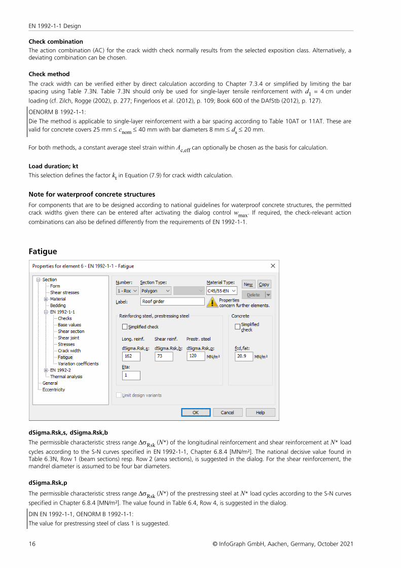
Checks in the Ultimate Limit StatesThe following checks are available:
• Bending with or without normal force or normal force only (EN 1992-1-1, Chapter 6.1).
• Minimum reinforcement against failure without warning (Chapter 5.10.1 (5)P and 9.2.1.1).
• Lateral force (Chapter 6.2).
• Torsion and combined stressing (Chapter 6.3).
• Punching shear (Chapter 6.4).
Design CombinationsIn accordance with EN 1990 (Eurocode 0), Chapter 6.4.3, the following combinations are taken into account in the ultimatelimit states:
• For the combination of the permanent and temporary design situation either Equation (6.10) or the most unfavorableequation from (6.10a) and (6.10b) is permitted.
å å³ >
×y×g+×g+×g+×g1j 1i
k,i0,iQ,ik,1Q,1Pjk,jG, """""" QQPG(6.10)
å å³ >
×y×g+×y×g+×g+×g1j 1i
k,i0,iQ,ik,110,Q,1Pjk,jG, """""" QQPG(6.10a)
å å³ >
×y×g+×g+×g+×g×x1j 1i
k,i0,iQ,ik,1Q,1Pjk,jG,j """""" QQPG(6.10b)
For the coefficient x the value of x = 0.85 results from Table A.1.2(B).
DIN EN 1990, OENORM B 1990:Equation (6.10) is used for the combination.
SS EN 1990:Equations (6.10a) and (6.10b) apply with following modifications:
å³
×g+×g×g1j
Pjk,jG, "" PGd (6.10aSS)
å å³ >
×y×g×g+×g×g+×g+×g×g×x1j 1i
k,i0,iQ,ik,1Q,1Pjk,jG,j """""" QQPG ddd (6.10bSS)
Assuming reliability class 3, factor gd is set to 1. (see Section A, Article 11 and 14). The coefficient x is set to the value
of x = 0.89.
BS B 1990:
The coefficient x in Equation (6.10b) is set to the value of x = 0.925.
• Combination for accidental design situations
å å³ >
×y+×yy+++1j 1i
k,i2,ik,12,11,1djk, "")or("""""" QQAPG(6.10b)
y1,1 · Qk,1 is used by the program for this combination.
OENORM B 1990-1:
y2,1 · Qk,1 is decisive.
• Combination for design situations caused by earthquakes
å å³ ³
×y+++1j 1i
k,i2,iEdjk, """""" QAPG(6.12b)
For each combination you can define different design situations for the construction stages and final states. Whenconducting the check, the extreme value deriving from all combinations and situations is decisive.

36
EN 1992-1-1 Design
© InfoGraph GmbH, Aachen, Germany, October 2021
Stress-Strain CurvesThe following characteristics are used for section design:
• Concrete: Parabola-rectangle diagram according to EN 1992-1-1, Figure 3.3. Note that the design value for concrete
compressive strength fcd in Equation (3.15) is defined as fcd = acc·fck / gc with acc = 1 for normal concrete and acc = 0.85
for lightweight concrete.
DIN EN 1992-1-1:
acc = 0.85 for normal concrete and acc = 0.75 for lightweight concrete.
SS EN 1992-1-1:
acc = 1 for normal and lightweight concrete.
BS EN 1992-1-1:
According to NA to 3.1.6 (1)P conservatively, acc = 0.85 is always assumed for normal concrete and lightweight
concrete.
• Reinforcing steel: Stress-strain curve according to EN 1992-1-1, Figure 3.8, with rising upper branch, where the
maximum stress is assumed to be k · fyk / gs with k = 1.05 as per Table C.1, class A.
DIN EN 1992-1-1:
The maximum stress is assumed to be 1.05 · fyk / gs for ductility class A according to DIN 488-1.
• Prestressing steel: Stress-strain curve according to EN 1992-1-1, Figure 3.10, with horizontal upper branch according to
Chapter 3.3.6 (7) of the standard and a maximum stress of fpd = fp;0,1k / gs .
Design for Bending With or Without Normal Force or Normal Force OnlyThe design for longitudinal force and bending moment is performed according to EN 1992-1-1, Chapter 6.1. Thereinforcement required for each internal force combination at the reinforced concrete section is determined iteratively basedon the formulation of equilibrium conditions as well as the limit strain curve depicted in the illustration below. The finalresult is derived from the extreme value of all calculated reinforcements.
Strain areas for the design with eud = 0.9 euk and euk = 0.025 as per Table C.1.
DIN EN 1992-1-1:
eud = 0.025
You can control the result of the design by specifying the reinforcement geometry and choosing one of three designmodes. For sections subject to a compressive normal force, the minimum eccentricity defined in Chapter 6.1 (4) is taken intoaccount. Concrete compression according to Chapter 6.1 (5) cannot be checked.
Standard Mode
This is the standard design mode for bending with longitudinal force throughout the entire load area. Reinforcement will becalculated in the tensile section to the greatest degree possible. The procedure in strain areas 4 and 5 is the same as withsymmetrical design. The required transverse reinforcement of slab as per Section 9.3.1.1 (2) is considered during designaccording to user specification. However, the provision for horizontal reinforcement of walls as per Section 9.6.3 (1) is nottaken into account.

37
Checks in the Ultimate Limit States
© InfoGraph GmbH, Aachen, Germany, October 2021
DIN EN 1992-1-1:The referenced compressive zone height xd / d is limited according to Chapter 5.4 (NA.5) and NA.11.5.2 (1) as follows:
xd / d £ 0.45 for concrete strength classes up to C50/60.
£ 0.35 for concrete strength class C55/67 or higher and for lightweight concrete.
Symmetrical Mode
In contrast to the standard design, the reinforcement will be applied at all predefined locations in all strain areas, ifnecessary. The specified ratios between the reinforcement layers will not be affected unless this is deselected in the designspecifications.
Compression member Mode
The design is performed symmetrically. In addition, the minimum reinforcement required by EN 1992-1-1, Chapter 9.5.2 (2),will be calculated:
As,min = 0.10 | NEd | / fyd or 0.002 Ac, depending on which value is greater (9.12N)
withNEd Design value of the longitudinal force to be absorbed.
fyd Design value for the reinforcing steel strength at the yield strength.
DIN EN 1992-1-1:
As,min = 0.15 NEd / fyd(9.12DE)
OENORM B 1992-1-1:
As,min = 0.13 NEd / fyd ³ 0.0026 Ac(30AT)
SS EN 1992-1-1:
As,min = 0.002 Ac(Article 28)
Inclusion of tendons with bond
When designing beams and design objects, the internal forces of the concrete section is reduced by the staticallydetermined portions which result from prestressing minus the losses from creep, shrinkage and prestressing steel relaxation(CSR). Situations prior to the grouting of the tendons are excluded. So only the restraint portions from 'P+CSR' and theexternal loads are contained in the remaining internal forces for the composite section. If necessary, the reinforcing steelpositioned by the user will be increased until the composite internal forces can be absorbed.
The position of the tendon groups in the section, the prestressing losses from CSR, the statically determined portions andthe internal forces of the concrete section and the composite section are written to the detailed log.
As a separation into statically determined and undetermined shares of the internal forces from prestressing is not possiblefor shell structures, the prestressing is taken into account fully on the action side when designing the longitudinalreinforcement. As a result, on the resistance side only mild steel and concrete are considered whereas the strain reserves ofthe tendons with bond are not used.

38
EN 1992-1-1 Design
© InfoGraph GmbH, Aachen, Germany, October 2021
Minimum Reinforcement Against Failure Without WarningWith respect to prestressed concrete structures, a component failure without warning may not be caused by a tendonfailure according to EN 1992-1-1, Chapter 5.10.1 (5)P. The failure can be prevented by adding the minimum reinforcementas described in Chapter 9.2.1 or any other measure listed in Section (6).
The minimum reinforcement is to be dimensioned according to Chapter 9.2.1 with Equation (9.1N) (also applies toreinforced concrete components). To account for this in the program, specify a base reinforcement in the reinforcing steeldescription.
Alternatively, you can select the minimum reinforcement in the section dialog based on the methods specified forprestressed concrete bridges in EN 1992-2, Chapter 6.1 (109) (robustness reinforcement). This reinforcement is determinedbased on Equation (6.101a):
As,min= Mrep / (zs · fyk) (6.101a)
with
Mrep Crack moment without allowance for prestressing force and under the assumption that the edge tensile stress
corresponds to fctm. According to Chapter 9.2.1.1 (4), the 1.15-fold crack moment is used for components with
unbonded tendons or with external prestressing.
zs Lever arm of the internal forces in the ultimate limit state.
According to EN 1992-2, Chapter 6.1 (110), the minimum reinforcement should be added in areas where tensile stresses inthe concrete occur under the characteristic action combination. This process should take into account the staticallyundetermined prestressing effect and ignore the statically determined effect.
The program determines all stresses at the gross section. The statically determined prestressing effect can only be subtractedfor beams and design objects. For area elements the prestress is alternatively reduced by a user-defined reduction factor.The lever arm zs of the internal forces is assumed as 0.9 · d for the sake of simplicity. The calculated reinforcement is evenly
distributed to the reinforcement layers in the tensile zone. In the design mode symmetrical reinforcement is also applied tothe remaining layers. This will not affect the predefined relationships between the individual reinforcement layers. Forsections with mode compression member the robustness reinforcement is not checked because minimum reinforcement isalready determined during the design for bending with longitudinal force.
DIN EN 1992-1-1:
To ensure a ductile component behavior, the above-mentioned robustness reinforcement must be added instead of theminimum reinforcement from Equation (9.1N) for components with or without prestressing. The reinforcement must beevenly distributed in the tensile zone. As it is not specified in more detail, this reinforcement is determined with thecharacteristic combination as described above. The option to take tendons into account is not used by the program.
SS EN 1992-1-1:
According to Article 13, method D (proofs concerning the reliability of the tendons), in combination with at least one of theother methods, should be used. The second condition can be covered by adding the minimum reinforcement as describedin Chapter 9.2.1 (method A) or by use of the above-mentioned robustness reinforcement.
Surface ReinforcementTo prevent concrete spalling, a surface reinforcement may be necessary according to EN 1992-1-1, Chapter 9.2.4. For moreinformation, refer to Annex J. The reinforcement determined in this manner can be incorporated into the program byspecifying a base reinforcement in the reinforcing steel description.
OENORM B 1992-1-1:
The guidelines set forth in Annex J are not normative.

39
Checks in the Ultimate Limit States
© InfoGraph GmbH, Aachen, Germany, October 2021
Design for Lateral ForceLateral force design involves determining the lateral force reinforcement and includes a concrete strut check according toEN 1992-1-1, Chapter 6.2. The following special conditions apply:
• The angle of the lateral force reinforcement is assumed to be 90°.
• The value for cot Q can be selected by the user within the permissible national limits of Equation (6.7N).
DIN EN 1992-1-1:
In the calculation, the specified value for cot Q is limited to the range permitted in accordance with Equation (6.7aDE)(method with load-dependent strut angle), unless the check with a constant value is selected in the section dialog. Theactual effective angle of the concrete struts is logged for each check location.
• The minimum reinforcement according to Chapter 9.2.2 (5) of the standard is included in the calculated stirrupreinforcement. For areas, the minimum reinforcement as per Chapter 6.2.1 (4) will only be determined if the lateralforce reinforcement is necessary for computation. For beams no minimum reinforcement is calculated for the directionwith M = Q = 0.
• For beams and design objects, the shear design is performed separately for the Qy and Qz lateral forces.
• Slab and shell elements are designed for lateral force qr = Ö(qx² + qy²). Depending on which has a negative effect,
either the principal compressive force or principal tensile force is used for the associated longitudinal force.
DIN EN 1992-1-1:If selected, the check will be carried out separately for the reinforcement directions x and y in accordance withChapter 6.2.1 (10). In this case, the normal force in reinforcement direction is used for the associated longitudinalforce. If lateral force reinforcement is necessary, it must be added from both directions.
• There is no reduction of the action from loads near supports as specified in Chapter 6.2.1 (8) of the standard.
• For beams and design objects, the decisive values of the equivalent rectangle are determined by the userindependently of the normal section geometry. The coefficients for calculating the inner lever arm z based on theeffective width and effective height must also be specified. For area elements, the calculation is generally performedwith the lever arm z = 0.9 d.
• DIN EN 1992-1-1:According to 6.2.3 (1), the inner lever arm is limited to the maximum value derived from z = d - cv,l - 30 mm and z = d – 2cv,l. Note that cv,l refers to the extent to which longitudinal reinforcement is laid in
the concrete compressive zone.
• For beam sections with internal prestressing, the design value of lateral load-bearing capacity VRd,max according to
Chapter 6.2.3 (6) is determined using the nominal value bw,nom of the section width.
• The necessity of a lateral force reinforcement is analyzed according to Chapter 6.2.2 (1) of the standard. The specialconditions listed in Sections (2) through (7) are not used in this case.
• BS EN 1992-1-1:The shear strength of concrete of strength classes higher than C50/60 is limited to the value of class C50/60,according to NA to 3.1.2 (2)P.
The used formulas from EN 1992-1-1 that are used are listed below.
Components without computationally necessary lateral force reinforcement
VRd,c = [CRd,c · k · (100 rl · fck)1/3 + k1 · scp] bw · d (6.2a)
with at least
VRd,c = ( vmin + k1 · scp ) bw · d (6.2b)
For lightweight concrete applies:
VlRd,c = [ClRd,c · h1 · k · (100 rl · flck)1/3 + k1 · scp] bw · d
³ ( h1 · vl,min + k1 · scp) bw · d(11.6.2)
where
fck , flck is the characteristic concrete strength [N/mm²].
k = 1 + Ö(200 / d ) £ 2.0 with d specified in mm.
rl = Asl / (bw · d ) £ 0.02.
Asl is the area of the tensile reinforcement that extends at least ( lbd + d ) beyond the analyzed section
(see Figure 6.3).
bw is the smallest section width in the tensile zone of the section [mm].

40
EN 1992-1-1 Design
© InfoGraph GmbH, Aachen, Germany, October 2021
scp = NEd / Ac < 0.2 fcd [N/mm²].
NEd is the normal force in the section due to loading or prestressing [N]
(NEd > 0 for compression). The influence of the forced deformations on NEd can be ignored.
Ac is the entire area of the concrete section [mm²].
VRd,c , VlRd,c is the design value of the lateral force resistance [N].
h1 is the reduction coefficient for lightweight concrete according to Eq. (11.1).
The recommended values are:
CRd,c = 0.18 / gc for normal concrete.
ClRd,c = 0.15 / gc for lightweight concrete.
k1 = 0.15
vmin = 0.035 k3/2 · fck1/2 for normal concrete. (6.3N)
vl,min = 0.028 k3/2 · flck1/2 for lightweight concrete according to 11.6.1 (1).
DIN EN 1992-1-1:
CRd,c = ClRd,c = 0.15 / gc
k1 = 0.12
vmin = (k1 / gc) k3/2 · fck
1/2
vl,min = (k1 / gc) k3/2 · flck
1/2
with
k1 =0.0525 for d < 600 mm
=0.0375 for d > 800 mm
For 600 mm < d £ 800 mm can be interpolated.
Components with computationally necessary lateral force reinforcement
The angle q between the concrete struts and the component axis perpendicular to the lateral force must be limited:
1 £ cot q £ 2.5 (6.7N)
DIN EN 1992-1-1:
1.0 £ cot q £ (1.2 + 1.4 scp / fcd) / (1 - VRd,cc / VEd) £ 3.0 (6.7aDE)
with
VRd,cc = c · 0.48 · fck1/3 (1 - 1.2 scp / fcd) · bw · z (6.7bDE)
The individual parts of which are
c = 0.5
scp The design value of the concrete longitudinal stress at the level of the centroid of the
section with scp = NEd / Ac in N/mm².
NEd The design value of the longitudinal force in the section caused by external actions
(NEd > 0 as longitudinal compressive force).
For lightweight concrete the strut angle is to be limited to cot q = 2 in accordance with Eq. (6.7aDE). The input value
VRd,cc from Eq. (6.7bDE) is to be multiplied by h1 according to Eq. (11.1).
OENORM B 1992-1-1:
0.6 £ tan q £ 1.0 (3AT)
If the section is in compression, then q in the range
0.4 £ tan q £ 1.0 (4AT)
may be selected.

41
Checks in the Ultimate Limit States
© InfoGraph GmbH, Aachen, Germany, October 2021
SS EN 1992-1-1:
According to Article 15 and differing from Equation (6.7N), for prestressed components the condition 1.0 £ cot Q £ 3.0applies.
For components with lateral force reinforcement perpendicular to the complement axis, the lateral force resistance VRd is
the smaller value from
VRd,s = (Asw / s) · z · fywd · cot q (6.8)
and
VRd,max = acw · bw · z · n1 · fcd / (cot q + tan q) (6.9)
where
Asw is the section area of the lateral force reinforcement.
s is the distance of the stirrups to each other.
fywd is the design value for the yield strength of the lateral force reinforcement.
n1 is a reduction coefficient for the concrete strength when shear cracks occur.
acw is a coefficient for taking into account the stress state in the compression chord.
The recommended values are:
n1 = n
with
n = 0.6 (1 - fck / 250) for normal concrete ( fck in N/mm²) (6.6N)
n = 0.5 h1 (1 - flck / 250) for lightweight concrete ( flck in N/mm²) (11.6.6N)
acw= 1 for non-prestressed components
= (1 + scp / fcd) for 0 < scp £ 0.25 fcd(6.11aN)
= 1.25 for 0.25 fcd < scp £ 0.5 fcd(6.11bN)
= 2.5 (1 - scp / fcd) for 0.5 fcd < scp £ 1.0 fcd(6.11cN)
where
scp is the average compressive stress in the concrete (indicated as a positive value) as a result of the design value for
the normal force.
The maximum effective section area of the lateral force reinforcement Asw,max for cot q = 1 is derived from:
(Asw,max · fywd) / (bw · s) £ ½ acw · n · fcd (6.12)
The additional tensile force in the longitudinal reinforcement due to lateral force according to Eq. (6.18) is
DFtd = 0.5·VEd·(cot Q - cot a ). (6.18)
DIN EN 1992-1-1:
n1 = h1 · 0.75 · min (1.0; 1.1 - fck / 500)
h1= 1.0 for normal concrete and as per Eq. (11.1) for lightweight concrete.
acw= 1.0
Equation (6.12) is not applied.
Lateral force reinforcement
The lateral force reinforcement level is derived from Equation (9.4):
rw = Asw / (s · bw · sin a) (9.4)
where
rw is the reinforcement level of the lateral force reinforcement. In general, this level may not be smaller than rw,min.
Asw is the section area of the lateral force reinforcement per length s.
s is the distance of the lateral force reinforcement as measured along the component axis.
bw is the web width of the component.
a is the angle between the lateral force reinforcement and the component axis.

42
EN 1992-1-1 Design
© InfoGraph GmbH, Aachen, Germany, October 2021
The recommended value for the minimum reinforcement is:
rw,min = 0.08 Öfck / fyk (9.5N)
DIN EN 1992-1-1:
rw,min = 0.16 fctm / fyk (9.5aDE)
With respect to slabs, the value can vary between zero and the above value as described in Chapter 9.3.2 (2).
For structured sections with prestressed tension chord, the following applies:
rw,min = 0.256 fctm / fyk (9.5bDE)
OENORM B 1992-1-1:
rw,min = 0.15 fctm / fyd (24AT)
For slabs with a calculated shear reinforcement at least the 0.6-fold value of the minimum shear reinforcement of beams isto be applied.
Design for Torsion and Combined StressingThe design for torsion is carried out according to EN 1992-1-1, Chapter 6.3. It includes the calculation of the diagonaltensile reinforcement and the longitudinal reinforcement based on Equation (6.28) and the concrete strut check underlateral force based on Formula (6.29) of the standard.
The equivalent section on which this design is based is defined by the user independently of the normal section geometry.
Strut angle
According to 6.3.2 (2), the rules set forth in Chapter 6.2.3 (2) for lateral force also apply for the strut angle.
DIN EN 1992-1-1:
For combined stress from torsion and proportional lateral force, VEd in Equation (6.7aDE) must include the shear force of
the wall VEd,T+V based on Equation (NA.6.27.1) and bw in Equation (6.7bDE) must include the effective thickness of wall tef.
The check for both lateral force and torsion must be carried out using the selected angle Q. The reinforcements determinedin this manner are to be added together.
VEd,T+V = VEd,T + VEd · tef / bw (NA.6.27.1)
Alternatively a strut angle of 45° for torsion according to Chapter 6.3.2 (2) or a constant value cot Q for lateral force andtorsion (cf. interpretation No. 24 of NABau for DIN 1045-1) can be chosen in the section dialog.
Torsion reinforcement
The necessary reinforcement is to be determined according to Chapter 6.3.2 (3):
SAsl · fyd / uk = TEd / 2Ak · cot Q
or
Asw · fyd / s = TEd / 2Ak · tan Q
(6.28)
where
Asl is the section area of the torsion longitudinal reinforcement.
Asw is the section area of the torsion reinforcement perpendicular to the component axis.
uk is the perimeter of area Ak.
s is the distance of the torsion reinforcement as measured along the component axis.
Ak is the area enclosed by the center lines of the walls.
For approximately rectangular full sections, only the minimum reinforcement defined in Section (5) is necessary if thecondition expressed by Equation (6.31) is met:
TEd / TRd,c + VEd / VRd,c £ 1.0 (6.31)

43
Checks in the Ultimate Limit States
© InfoGraph GmbH, Aachen, Germany, October 2021
where
TRd,c is the torsion crack moment which, according to Zilch (2006, p. 290), is defined as TRd,c = fctd · WT.
VRd,c is the lateral force resistance according to Equation (6.2).
DIN EN 1992-1-1:
The condition (6.31) is supplemented with the following equations:
5.4wEd
EdbV
T×
£(NA.6.31.1)
cRd,wEd
EdEd
5.41 V
bV
TV £ú
û
ùêë
é
×+
(NA.6.31.2)
Strut load-bearing capacity
To avoid exceeding the strut load-bearing capacity of a component subject to torsion and lateral force, the followingcondition must be met:
TEd / TRd,max + VEd / VRd,max £ 1.0 (6.29)
where
TEd is the design value of the torsion moment.
VEd is the design value of the lateral force.
TRd,max is the design value of the absorbable torsion moment based on
TRd,max = 2 n · acw · fcd · Ak · tef,i · sin Q · cos Q (6.30)
with acw according to Equation (6.9) and n according to Eq. (6.6N) for normal concrete and
according to Eq. (11.6.6N) for lightweight concrete.
DIN EN 1992-1-1:
For compact sections, the interaction Equation (NA.6.29.1) is used:
(TEd / TRd,max)² + (VEd / VRd,max)² £ 1.0 (NA.6.29.1)
In Equation (6.30) n = h1 · 0.75 is used for box sections and n = h1 · 0.525 · min (1.0; 1.1 - fck / 500) in all other cases with
h1 = 1 for normal concrete and as per Eq. (11.1) for lightweight concrete.
OENORM B 1992-1-1:
For full sections the following interaction equation can be used:
(TEd / TRd,max)² + (VEd / VRd,max)² £ 1.0 (9AT)

44
EN 1992-1-1 Design
© InfoGraph GmbH, Aachen, Germany, October 2021
Shear Joint CheckThe shear joint check is peformed for beam elements and design objects in accordance with EN 1992-1-1, Chapter 6.2.5. Itis carried out for the shear force in the z-direction of the cross-section and is only useful for components that are mainlystressed in this direction. The transmission of shear force through the joint is ensured if the following conditions are met:
vEdi £ vRdi (6.23)
Design value of the shear stress in the joint vEdi:
vEdi = β · VEd / (z · bi) (6.24)
whereβ is the ratio of the longitudinal force in the new concrete area and the total longitudinal force either in the
compression or tension zone, both calculated for the section considered. The ratio factor β is calculateddepending on whether the shear joint is in the compression or tension zone and whether reinforcement in theexisting concrete or in the concrete supplement was determined from the other checks with the internal forcesassociated with VEd in state II as follows (see also Booklet 600 to 6.2.5 (1)):
Outer edge of Shear joint Tensile reinforcement ß
concrete supplement Concrete supplement
Existing Concrete
Tension Ten. / Comp. - - 1
Compression Compression - - 0 < Fcdi / Fcd < 1
Tension Yes Yes 0 < Fsd / (Fsd + Fsdi) < 1
Yes No 0 (No check)
No Yes 1
No No 0 (No check)
VEd is the design value of the lateral force in the z direction.
z is the lever arm of the composite section. The lever arm is assumed as in the lateral force check according to thespecifications in the shear section.
bi is the width of the joint.
Fcdi is the concrete compression force in the concrete supplement in the compression zone.
Fcd is the total concrete compression force in the compression zone.
Fsdi is the tension force of the reinforcing steel layers in the concrete supplement in the tensile zone.
Fsd is the total tension force of the reinforcing steel layers in the tensile zone.
Design value of the shear resistance in the joint vRdi:
vRdi = c · fctd + m · sn + ρ · fyd (m · sin a + cos a) £ 0.5 · ν · fcd(6.25)
DIN EN 1992-1-1:
The load bearing component of the transverse reinforcement from the shear friction in Eq. (6.25) may be increased to
r · fyd (1.2 · m · sin a + cos a).
For very smooth joints without external compression normal force perpendicular to the joint, the friction component in
Eq. (6.25) may be taken into account up to the limit m · sn £ 0.1 · fcd according to NPD 6.2.2 (6).
where
c, m are factors which depend on the roughness of the joint (see 6.2.5 (2)). Under dynamic or fatigue loads, the
value c is halved according to 6.2.5 (5).
DIN EN 1992-1-1:
For very smooth joints under dynamic or fatigue loads, c = 0 is to be assumed.
fctd is the design value of the concrete tensile strength according to 3.1.6 (2)P.
sn is the stress caused by the minimum normal force perpendicular to the joint, which can act simultaneously with
the lateral force (positive for compression with sn < 0.6 fcd and negative for tension). If sn is a tensile stress
c · fctd should usually be set to 0.

45
Checks in the Ultimate Limit States
© InfoGraph GmbH, Aachen, Germany, October 2021
r = As / Ai
As is the area of reinforcement crossing the joint, including ordinary shear reinforcement, with adequate anchorage
at both sides of the interface.
Ai is the area of the joint.
a the angle of inclination of the transverse reinforcement. This is set at 90° by the program.
v is a strength reduction factor according to 6.2.2 (6).
OENORM B 1992-1-1:
If reinforcement is required, the following minimum reinforcement must be inserted perpendicular to the joint for beam-likecomponents:
ρmin = 0.2 · fctm / fyk ³ 0.001
Punching ShearThe load-bearing safety check against punching shear is carried out according to EN 1992-1-1, Chapter 6.4. This check isused to determine the necessary punching reinforcement. The following special conditions apply:
• The orthogonal effect directions labeled as y and z in the standard are indicated below as well as in the dialog and the
listing as x and y in order to comply with the area reinforcement directions commonly used in the program.
• The average effective static height d results from the input parameters dx and dy with d = (dx+dy) / 2. These
parameters are to be selected as shown in Figure 6.12, 6.16 or 6.17.
• No check is carried out for pad footings.
• The action can be entered directly or taken from the analyzed design situation at the ultimate limit state. In this case, VEd is set to the maximum support force Rz for each corresponding action combination.
• BS EN 1992-1-1:The shear strength of concrete of strength classes higher than C50/60 is limited to the value of class C50/60,according to NA to 3.1.2 (2)P.
The check is considered fulfilled if:
1. For slabs w i t h o u t punching reinforcement
vEd £ vRd,max ,
vEd £ vRd,c .
2. For slabs w i t h punching reinforcement
vEd £ vRd,max ,
vEd £ vRd,cs .
DIN EN 1992-1-1, OENORM B 1992-1-1:
3. The minimum longitudinal reinforcement is maintained
with
du
Vßv
×
×=
i
EdEd (6.38)
where
vEd is the maximum acting lateral force per area unit.
VEd is the design value of the entire lateral force to be absorbed. For foundation slabs the lateral force may be
reduced due to the favorable action of the soil pressure according to 6.4.3 (8). For the reduction the programassumes the area within u1 unless the national annex contains a different rule.
ß is the load increase factor for taking into account eccentric load introduction according to Equation (6.39). Thevalue is specified by the user.
DIN EN 1992-1-1, OENORM B 1992-1-1:
Values smaller then 1.10 are not permitted.
d is the average effective height of the slab, which can be assumed as (dx + dy) / 2, with:
dx, dy is the effective static height of the slab in the x or y direction in the section area of the analyzed perimeter.

46
EN 1992-1-1 Design
© InfoGraph GmbH, Aachen, Germany, October 2021
ui is the circumference of the analyzed perimeter.
vRd,c is the design value of the punching resistance per area unit for a slab without punching reinforcement.
vRd,cs is the design value of the punching resistance per area unit for a slab with punching reinforcement.
vRd,max is the design value of the maximum punching resistance per area unit.
The load discharge areas and check sections as per Chapter 6.4.2, Section (1) to (7), are taken into consideration. The user-specified opening dimensions are used to calculate the check sections.
Punching resistance without punching reinforcement
The punching resistance of a slab without punching reinforcement is calculated as
vRd,c = CRd,c · k · (100 rl · fck)1/3 + k1·scp ³ ( vmin + k1 · scp ) (6.47)
For lightweight concrete applies
vlRd,c = ClRd,c · k · h1 · (100 rl · flck)1/3 + k2·scp ³ ( h1 · vl,min + k2 · scp ) (11.6.47)
where
fck is the characteristic concrete strength [N/mm²]
k = 1 + Ö(200 / d) £ 2.0; d [mm]
rl = Ö(rlx · rly) £ 0.02
rlx, rly is the reinforcement level based on the fixed tensile reinforcement in the x or y direction. The values rlx and rly
are normally calculated as average values given a slab width based on the column measurements plus 3·d foreach side.
scp = (scx + scy) / 2
where
scx, scy are the normal stresses in the concrete in the x and y directions in the critical section (MN/m², positive for
pressure):
scx = NEd,x / Acx and scy = NEd,y / Acy.
NEd,x, NEd,y are the normal forces acting on internal columns in the entire section area of the analyzed perimeter and the
normal forces acting on the edge and corner columns in the area of the analyzed perimeter. These forces resultfrom loads or prestressing.
Ac is the section area of the concrete according to the definition of NEd.
The recommended country-specific values are:
CRd,c = 0.18 / gc for normal concrete
ClRd,c = 0.15 / gc for lightweight concrete
k1 = 0.1
k2 = 0.08
vmin derived from Equation (6.3N) for normal concrete:
vmin = 0.035·k3/2·fck1/2 (6.3N)
vl,min derived from Chapter 11.6.1 (1) for lightweight concrete:
vl,min = 0.028·k3/2·flck1/2
For column foundations and foundation slabs the following applies according to Chapter 6.4.4 (2):
vRd,c = CRd,c · k · (100 rl · fck)1/3 · 2 · d/a ³ ( vmin · 2 · d/a ) (6.50)
vlRd,c = ClRd,c · k · h1 · (100 rl · flck)1/3 · 2 · d/a ³ ( h1 · vl,min · 2 · d/a ) (11.6.50)
a Distance from the column edge to the decisive perimeter. Within the perimeter the soil pressures deducting thefoundation dead load are allowed for relieving.

47
Checks in the Ultimate Limit States
© InfoGraph GmbH, Aachen, Germany, October 2021
DIN EN 1992-1-1:
vmin as in Section 6.2.2 (1)
For internal columns of flat slabs with u0 /d < 4 the following applies according to Book 600 of the DAfStb:
CRd,c = ClRd,c = 0.18 / gc · ( 0.1·u0 /d + 0.6 ) ³ 0.15/gc (H.6-16)
For column foundations and foundation slabs the following applies:
a The program does not iterate over the distance a according to NCI of 6.4.4 (2). If a constant perimeter with
a = 1.0 d is assumed, only 50% of the soil pressures are allowed for relieving. This is taken into account duringdetermination of the resistance.
CRd,c = ClRd,c = 0.15 / gc
In all other cases the recommended value for CRd,c applies.
The bending reinforcement level rl must also be limited to rl £ 0.5 fcd / fyd.
OENORM B 1992-1-1:
The allowable reinforcement level for determining vRd,c must not exceed
rl = 0.4 · fcd / fyd £ 0.02.
For foundation slabs the program does not iterate over the distance a according to the supplement to 6.4.4 (2). For
simplification, a constant perimeter with a = 1.0 d can be assumed.
Punching resistances with punching reinforcement
1) The punching resistances with punching reinforcement are calculated as
vEd = ß·VEd / ( u0·d ) £ vRd,maxfor normal concrete (6.53)
vEd = VEd / ( u0·d ) £ vlRd,maxfor lightweight concrete (11.6.53)
whereu0
For an internal column u0 = Circumference of the column
For an edge column u0 = c2 + 3·d £ c2 + 2·c1
For a corner column u0 = 3·d £ c1 + c2
c1, c2 are the column dimensions as shown in Figure 6.20. For circular columns, the decisive values of u0 are
determined proportionally. For walls u0 is determined corresponding to edge and corner columns.
OENORM B 1992-1-1: The possibility of simplification in case of round edge and corner columns is not used.
ß See 6.4.3 (3), (4) and (5).
vEd is the lateral force to be absorbed at the column section per area unit.
The recommended country-specific values are:
vRd,max = 0.4 · v · fcd with v as per Eq. (6.6N)
vlRd,max = 0.4 · v · flcd with v as per Eq. (11.6.6N)
DIN EN 1992-1-1:
The maximum punching resistance is determined within the critical perimeter u1 :
vEd,u1 £ vRd,max = 1.4 · vRdc,u1
Deviating from NDP of 6.4.5 (3), vRdc,u1 is set to vRd,c according to Eq. (6.47).
(NA.6.53.1)
OENORM B 1992-1-1:
For slabs or foundations with small load introduction areas with u0/d < 4, the maximum punching resistance vRd,max shall
be limited to the recommended values.
SS EN 1992-1-1:
vRd,max £ 0.50 · v · fcd(Article 16)
vRd,max £ 0.50 · v · flcd(Article 36a)
BS EN 1992-1-1:
vRd,max = 0.5 · v · fcd
For lightweight concrete the recommended value applies.

48
EN 1992-1-1 Design
© InfoGraph GmbH, Aachen, Germany, October 2021
2) The first reinforcement row is specified with a distance of 0.5·d from the column edge; the other reinforcement rows are
specified with a distance of sr £ 0.75·d from each other (see Figure 9.10). The reinforcement is determined using the
following equation:
vRd,cs = 0.75·vRd,c + 1.5·(d / sr) Asw· fywd,ef ( 1/(u1·d)) sin a £ kmax·vRd,c [MN/m²] (6.52)
whereAsw is the section area of the punching reinforcement in a reinforcement row around the column [mm²].
sr is the radial distance of the punching reinforcement rows [mm].
fywd,ef is the effective design value for the yield strength of the punching reinforcement according to
fywd,ef = 250 + 0.25·d £ fywd [MN/m²]
u1 is the circumference of the critical perimeter [mm].
d is the average value of the effective static heights in the orthogonal directions [mm].
a is the angle between the punching reinforcement and the slab plane.
kmax is the factor for limiting the maximal load-bearing capacity with punching reinforcement. The recommendedvalue is 1.5.
BS EN 1992-1-1: kmax = 2.0
SS EN 1992-1-1: kmax = 1.6
For bent-down reinforcement d / sr = 0.67 is used according to Section 6.4.5 (1).
DIN EN 1992-1-1:
Within the perimeter uout as per Section 6.4.5 (4), a minimum of two reinforcement rows is always required. For the first
two reinforcement rows of flat slabs, Asw is to be increased by the factors ksw,1 = 2.5 resp. ksw,2 = 1.4. For bent-down
punching shear reinforcement d / sr = 0.53 is used. The bent-down reinforcement can be exploited with fywd,ef = fywd. For
foundation slabs the stirrup reinforcement is calculated according to the following Equation:
ß · VEd,red £ VRd,s = Asw,1+2 · fywd,ef (NA.6.52.1)
For bent-down reinforcement:
ß · VEd,red £ VRd,s = 1.3 Asw,1+2 · fywd sin a (NA.6.52.2)
In order to determine VEd,red, the reduction value DVEd in Eq. (6.48) is calculated using the area Acrit according to Figure
NA.6.21.1 for the first two reinforcement rows and Ai > Acrit for the following rows i > 2, whereas in each case only 50%
of the soil pressures are applied relieving. For the first two rows, 50% of the reinforcement amount determined withEq. (NA.6.52.1) are required whereas 33% should be installed in each of the following rows. The first reinforcement row isspecified with a distance of 0.3·d from the column edge. For the first three rows the distance sr between the rows should
be limited to 0.5·d.
OENORM B 1992-1-1:
For each of the first two rows Asw is to be increased by 60%. The coefficient kmax in Eq. (6.52) is assumed to be kmax
= 1.65. According to OENORM, it is assumed that the punching reinforcement comprises the respective lower layer of thebending reinforcement or consists of bent-up bars. For the given normal force NEd, it is assumed that it does not include a
compressive normal force from prestressing.
3) The perimeter uout,ef , which does not need any punching reinforcement, is normally calculated based on Equation (6.54):
uout,ef = ß·VEd / (vRd,c·d) (6.54)
In general, the outermost row of the punching reinforcement must not be farther from uout,ef than 1.5·d.
DIN EN 1992-1-1:
vRd,c is determined as the lateral force resistance according to Chapter 6.2.2 (1).

49
Checks in the Ultimate Limit States
© InfoGraph GmbH, Aachen, Germany, October 2021
4) For the minimum required punching reinforcement Asw,min of the internal check sections, the following applies:
( ) ( ) ( ) ykcktrminsw, /08.0/cossin5.1 ffssA ׳×a+a×× (9.11)
where
a is the angle between the punching reinforcement and the longitudinal reinforcement
(i.e., for vertical stirrups a = 90° and sin a = 1).
sr is the radial distance of the stirrups of the punching reinforcement.
st is the tangential distance of the stirrups of the punching reinforcement.
fck in N/mm².
DIN EN 1992-1-1:
tr ssffAA ×××=a×= ykcksminsw, /5.1/08.0sin (9.11DE)
5) Minimum longitudinal reinforcement
DIN EN 1992-1-1:
The minimum reinforcement is found according to Chapter 6.4.5 (NA.6) based on the design of the minimum moments:
mEd,x = hx · VEd and mEd,y = hy · VEd (NA.6.54.1)
with
hx, hy the moment coefficient as per Table NA.6.1.1 for the x or y direction.
OENORM EN 1992-1-1:
The minimum reinforcement is determined according to Equation (28AT):
effyd
Edmins,
9.0 b
e
fd
Va ×
××= (28AT)
with
e/beff the relative eccentricity as per Table 13AT.

50
EN 1992-1-1 Design
© InfoGraph GmbH, Aachen, Germany, October 2021
Checks Against FatigueThe following checks according to EN 1992-1-1 are available:
• Fatigue of longitudinal reinforcement, shear reinforcement and prestressing steel (Chapter 6.8.5, 6.8.6)
• Fatigue of concrete under compressive stress (Chapter 6.8.7)
• Fatigue of the concret compressive struts under lateral force and torsion (Chapter 6.8.7 (3))
The user can select two alternative methods for design:
• Simplified check for the frequent action combination according to EN 1992-1-1, Chapter 6.8.6 (2), and EN 1990,Eq. (6.15b), taking the relevant traffic loads at serviceability limit state into account.
• Check with damage equivalent stress ranges for the fatigue combination according to EN 1992-1-1, Chapter 6.8.3,Eq. (6.69), considering the specific fatigue load Qfat.
The concrete compressive stresses are determined for both cases in state II. Differing from Chapter 5.10.9 the variation ofprestressing is not taken into account.
Design CombinationsFor the check against fatigue two alternative action combinations can be used:
• Frequent combination for simplified checks according to EN 1992-1-1, Chapter 6.8.6 (2) in conjunction with EN 1990,Chapter 6.5.3.
å å³ >
×y+×y++1j 1i
k,i2,ik,11,1jk, """""" QQPG(6.15b)
• Fatigue combination for checks with damage equivalent stress ranges.
fatQQQPG """"""""1j 1i
k,i2,ik,11,1jk, +÷÷
ø
ö
çç
è
æ×y+×y++å å
³ >
(6.69)
In this equation Qk,1 and Qk,i are non-cyclic, non-permanent actions whereas Qfat defines the relevant fatigue load.
For each combination you can define different design situations for the construction stages and final states. Whenconducting the check, the extreme value deriving from all combinations and situations is decisive.
Stress-Strain CurvesFor checks against fatigue the following characteristics apply:
• Concrete: Stress-strain curve according to EN 1992-1-1, Figure 3.2, where a horizontal curve is assumed for strains of
ec1 or higher (cf. Rossner, Graubner 2012, p. 511 and Nguyen et al. 2015, p. 158).
• Reinforcing steel: Stress-strain curve according to EN 1992-1-1, Figure 3.8, with rising upper branch, where themaximum stress is assumed to be k · fyk with k = 1.05 as per Table C.1, class A.
DIN EN 1992-1-1:
The maximum stress is assumed to be 1.05 · fyk / gs for ductility class A according to DIN 488-1.
• Prestressing steel: Stress-strain curve according to EN 1992-1-1, Figure 3.10, with horizontal upper branch according toChapter 3.3.6 (7) of the standard and a maximum stress of fp;0,1k .

51
Checks Against Fatigue
© InfoGraph GmbH, Aachen, Germany, October 2021
Fatigue of Longitudinal Reinforcement, Shear Reinforcement andPrestressing SteelThe fatigue check is carried out according to EN 1992-1-1, Chapter 6.8. The steel stresses are calculated for longitudinalreinforcement from bending and longitudinal force as well as for prestressing steel in beams and design objects under theassumption of a cracked concrete section. For shear and longitudinal reinforcement from lateral force and torsion, the
stresses are calculated according to 6.8.3 (3) based on a truss model with the strut angle tan Qfat = Ö tan Q £ 1 acc. to
Eq. (6.65). The prestressing steel stresses in area elements are determined at the uncracked concrete section. Tendonswithout bond and external tendons are not checked.
DIN EN 1992-1-1:
The strut angle is to be determined according to Eq. (H.6-26) of Book 600 of the DAfStb.
Simplified check
According to Chapter 6.8.6, adequate fatigue resistance may be assumed if the stress range under the frequent actioncombination does not exceed 70 MN/m² for unwelded reinforcing bars and 35 MN/m² for welded bars. The conditiondescribed in Chapter 6.8.6 (3) for couplings in prestressed components is not examined by the program.
DIN EN 1992-1-1:
The simplified check is not permitted for welded reinforcing bars.
Check with damage equivalent stress ranges
According to Chapter 6.8.5 (3), for reinforcing and prestressing steel adequate fatigue resistance should be assumed ifEq. (6.71) is satisfied:
gF,fat · Dss,equ(N*) £ DsRsk(N*) / gs,fat(6.71)
with
gF,fat = 1 according to Chapter 2.4.2.3 and 6.8.4 (1).
gs,fat = 1.15 for reinforcing and prestressing steel according to Chapter 2.4.2.4.
DsRsk(N*) Permitted characteristic stress range at N* load cycles based on the S-N curves specified in Tab. 6.4N for
prestressing steel or Tab. 6.3N for reinforcing steel.
Dss,equ(N*) Damage equivalent stress range with N* load cycles. For building construction this value may be
approximated by Dss,max .
Dss,max Maximum stress range from the fatigue combination.
Calculation method
The maximum from the robustness, crack and bending reinforcement is taken as the existing bending reinforcement. If as aresult the load from the fatigue combination in state II cannot be absorbed, the design will be repeated using the existingreinforcement and the check internal forces.
The maximum stress range per steel layer that results from the strain state in state II or the truss model is determinedseparately for each check situation. For longitudinal reinforcement the varying bond behavior of reinforcing and prestressing
steel is taken into account by increasing the steel stress by the coefficient h from Eq. (6.64). If for longitudinal and shearreinforcement the resulting stress range exceeds the permitted stress range, the necessary reinforcement will be iterativelyincreased until the check succeeds for all situations. In the Symmetrical and Compression member design modes thelongitudinal reinforcement is applied at all predefined locations. This will not affect the predefined relationships betweenthe individual reinforcement layers.
The permitted stress ranges and the coefficient h are specified by the user in the Section dialog.
The decisive reinforcement used for the check, which may have been increased, is recorded in the check log and saved forgraphical representation.

52
EN 1992-1-1 Design
© InfoGraph GmbH, Aachen, Germany, October 2021
Fatigue of Concrete Under Longitudinal Compressive StressThe fatigue check for concrete that is subject to compressive stress is performed for bending and longitudinal force at thecracked section as described in EN 1992-1-1, Chapter 6.8.7. This check takes into account the final longitudinalreinforcement and may include an increase applied during the fatigue check for reinforcing steel.
Simplified check
Adequate fatigue resistance may be assumed if the following condition is satisfied:
fatcd
c
fatcd
c
ff ,
min,
,
max,45.05.0
s+£
s £ 0.9 for fck £ 50 MN/m²
£ 0.8 for fck > 50 MN/m²(6.77)
where
sc,max is the maximum compressive stress at a fibre under the frequent load combination (compression measured
positive).
sc,min is the minimum compressive stress at the same fibre where sc,max occurs (sc,min = 0 if sc,min is a tensile stress).
fcd,fat is the design fatigue strength of concrete according to Eq. (6.76). This value is entered by the user in the Section
dialog.
fcd,fat = k1· ßcc(t0)· fcd ·(1 - fck / 250)
with ßcc(t0) as per Eq. (3.2) and fcd as per Eq. (3.15)(6.76)
k1 = 0.85
DIN EN 1992-1-1, OENORM B 1992-1-1, SS EN 1992-1-1:
k1 = 1.0
Check with damage equivalent concrete compressive stresses
According to Chapter 6.8.7 (1), a satisfactory fatigue resistance may be assumed for concrete under compression, ifEq. (6.72) is fulfilled:
1143.0max,, £-+ equequcd RE (6.72)
where
Requ = Ecd,min,equ / Ecd,max,equ is the stress ratio.
Ecd,min,equ = scd,min,equ / fcd,fat is the minimum compressive stress level.
Ecd,max,equ = scd,max,equ / fcd,fat is the maximum compressive stress level.
scd,min,equ is the lower stress of the ultimate amplitude for N = 106 cycles.
scd,max,equ is the uper stress of the ultimate amplitude for N = 106 cycles.
fcd,fat is the design fatigue strength of concrete according to Eq. (6.76).

53
Checks Against Fatigue
© InfoGraph GmbH, Aachen, Germany, October 2021
Fatigue of the Concrete Compressive Struts Under Lateral Force andTorsionFatigue of the concrete compressive struts is examined for beams and design objects. The check differentiates betweencomponents with and without calculatory required lateral force. In the case of combined loads from lateral force andtorsion, the supplementary condition according to Chapter EN 1992-1-1, 6.3.2 (5) is checked in addition to the condition inChapter 6.2.1 (5).
DIN EN 1992-1-1: In addition, the equations according to NCI for 6.3.2 (5) are evaluated.
Components with required lateral force reinforcement
The fatigue check for concrete under compressive stress as per Chapter 6.8.7, is also applicable for verifying the concretecompressive struts of components with required lateral force reinforcement as per Chapter 6.8.7 (3).
In the case of vertical stirrups (a = 90°), the design values scd,max and scd,min of the maximal and minimal compressive
stress may be determined according to the following equations while assuming an identical compressive strut angle q forlateral force and torsion as well:
Tcd,s
( )Q+Q×××
= tancot2 efk
Ed
tA
T
Vcd,s
( )Q+Q××
= tancotw
Ed
zb
V
maxcd,s
îíì
s+s
s+s=
Tcd,Vcd,
Vcd,Tcd,
.cormax
.cormax
mincd,s
îíì
s+s
s+s=
Tcd,Vcd,
Vcd,Tcd,
.cormin
.cormin
The program performs the check depending on the user’s selection either according to the simplified method as perEq. (6.77), for the frequent combination or by using the damage equivalent stress range as per Eq. (6.72), for the fatiguecombination given in Chapter 6.8.3, Eq. (6.69).When performing the simplified check under pure lateral force load, the concrete strength fcd,fat should be reduced by the
factor n · h1 as per Chapter 6.2.2 (6). In case of combined stressing from lateral force and torsion, the reduction factor
n · acw · h1 with acw as per Eq. (6.9) applies. The coefficient h1 should be set to 1 for normal concrete and according to
Eq. (11.1), for light weight concrete.
DIN EN 1992-1-1:The following factors apply:
n1 = 0.75 · n2 · h1 in case of pure lateral force as per NDP 6.2.3 (3).
n2 = (1.1 - fck / 500) £ 1.0
n · acw · h1 = 0.525 · h1 in case of combined stressing as per NDP 6.2.2 (6).
Components without required lateral force reinforcement
For components without required lateral force reinforcement at ultimate limit state, adequate fatigue resistance againstlateral force load may be assumed according to Chapter 6.8.7 (4), if the following conditions are satisfied:
for
cRd,
minEd,
cRd,
maxEd,
maxEd,
minEd,45.05.0:0
V
V
V
V
V
V×+£³
£ 0.9 for concrete up to C50/60
£ 0.8 for concrete C55/67 or higher(6.78)
for
cRd,
minEd,
cRd,
maxEd,
maxEd,
minEd,5.0:0
V
V
V
V
V
V-£< (6.79)
where
VEd,max is the design value of the maximum lateral force under the frequent action combination.
VEd,min is the design value of the minimum lateral force under the frequent action combination at the cross-
section where VEd,max occurs.
VRd,c is the design value of the absorbable lateral force without shear reinforcement as per Eq. (6.2a).
For performing the check, the program selects automatically the simplified method with the frequent action combination.

54
EN 1992-1-1 Design
© InfoGraph GmbH, Aachen, Germany, October 2021
Special Characteristic of Shell StructuresIn shell structures the strain state at the cracked concrete section under general stress cannot be determinedunambiguously. The design is therefore carried out separately for the reinforcement directions x and y with the designinternal forces from Wolfensberger/Thürlimann or Rüsch as described above. The reinforcement calculated in this manneryields a reliable load-bearing capacity.
When calculating the stress range for reinforcing steel and concrete, this method can lead to unrealistic results in the caseof torsional or shear stresses as shown in the following example:
Assume two identical sets of slab internal forces:Set mx [kNm/m] my [kNm/m] mxy [kNm/m] 1 300 200 100 2 300 200 100
According to Wolfensberger/Thürlimann, this results in design variants for the x direction:Set Variant m [kNm/m] 1 1 mx + |mxy| = 400 2 mx - |mxy| = 200 2 1 mx + |mxy| = 400 2 mx - |mxy| = 200
The torsional moments generate a variation of the design moments and thus a calculatory stress range. This may lead to anecessary reinforcement increase in the fatigue check due to apparent overstressing. For normal design forces, this appliescorrespondingly to the shear forces.
Selecting Limit design variants in the Section dialog allows you to avoid the described effect. In this case only thecorresponding variants are compared when determining the stress range, i.e. only the first and second variants of both setsin this example. Assuming constant stress, the stress range is thus correctly determined to be zero.
This alternative, however, does not ensure that all conceivable stress fluctuations are analyzed. You shouldtherefore be particularly careful when assessing the results. For this purpose the detailed log indicates the mainvariants and design internal forces used for the check.
When determining the design internal forces according to Rüsch for inclined reinforcement, the described relationshipsapply accordingly.

55
Checks in the Serviceability Limit States
© InfoGraph GmbH, Aachen, Germany, October 2021
Checks in the Serviceability Limit StatesThe following checks are performed:
• Limiting the concrete compressive stresses (EN 1992-1-1, Chapter 7.2).
• Limiting the reinforcing steel stresses (Chapter 7.2).
• Limiting the prestressing steel stresses (Chapter 7.2).
• Decompression check (Chapter 7.3.1).
• Minimum reinforcement for crack width limitation (Chapter 7.3.2).
• Crack with calculation (Chapter 7.3.4).
• Limiting deformations (Chapter 7.4).
Design CombinationsIn accordance with EN 1990 (Eurocode 0), Chapter 6.5.3, the following combinations are taken into account in theserviceability limit states:
• Combination for characteristic situations
å å³ >
×y+++1 1
k,i0,ik,1jk, """"""j i
QQPG (6.14b)
• Combination for frequent situations
å å³ >
×y+×y++1 1
k,i2,ik,11,1jk, """"""j i
QQPG (6.15b)
• Combination for quasi-continuous situations
å å³ ³
×y++1 1
k,i2,ijk, """"j i
QPG (6.16b)
For each combination you can define different design situations for the construction stages and final states. If necessary, thecombination required by the check will automatically be determined from the section specifications. Each check is carriedout for all the situations of a combination.
Stress-Strain CurvesFor checks in the serviceability limit states the following characteristics apply:
• Concrete: Stress-strain curve according to EN 1992-1-1, Figure 3.2, where a horizontal curve is assumed for strains of
ec1 or higher (cf. Interpretation No. 098 of the NABau for DIN TR 102).
• Reinforcing steel: Stress-strain curve according to EN 1992-1-1, Figure 3.8, with rising upper branch, where themaximum stress is assumed to be k · fyk with k = 1.05 as per Table C.1, class A.
DIN EN 1992-1-1:
The maximum stress is assumed to be 1.05 · fyk for ductility class A according to DIN 488-1.
• Prestressing steel: Stress-strain curve according to EN 1992-1-1, Figure 3.10, with horizontal upper branch according toChapter 3.3.6 (7) of the standard and a maximum stress of fp;0,1k .
Stress AnalysisFor uncracked concrete sections, the program assumes that concrete and steel under tensile and compressive stress behaveelastically. As for cracked concrete sections, the concrete compressive stresses are determined using the aforementionedstress-strain curve.
Area elements
For area elements the concrete stresses are calculated at the gross section. The steel stress check is carried out forreinforcing steel by determining the strain state at the cracked concrete section and for the prestressing steel at theuncracked concrete section.
Beams and design objects
The action combination stresses that can be determined without checks are always calculated at the gross section.

56
EN 1992-1-1 Design
© InfoGraph GmbH, Aachen, Germany, October 2021
Conversely, in the checks the stresses are determined as follows and are graphically displayed or logged:
• When checking the crack reinforcement and crack width, the concrete stress is calculated at the gross section
• When checking the decompression and concrete compressive stresses, the concrete stress is calculated- without internal tendons at the gross section- with internal tendons without bond at the net section- with internal tendons with bond for situations before being grouted at the net section or otherwise at the ideal
section
• The reinforcing and prestressing steel stresses are checked by determining the strain state at the cracked concretesection
OENORM B 1992-1-1:
If the stresses according to Chapter 7.2 are calculated at the cracked section the different bonding behavior of concrete
and prestressing steel is to be taken into account. The increase of tension force DFtp in the prestressing steel is to be
calculated as follows:
DFtp = x1² · Ap · e ( yp ) · Ep (14AT)
where
x1 is the bond coefficient according to Eq. (7.5); the value can be entered in the crack width check dialog;
Ap is the section area of the tendon with bond;
e ( yp ) is the strain of the concrete section at the location yp of the tendon;
Ep is the elasticity modulus of the tendon.
For beams and design objects this rule is taken into account by the program for situations after grouting. For areaelements it is not used because prestressing steel is only checked at the uncracked section.
Limiting the Concrete Compressive StressesThe concrete compressive stress check is carried out according to EN 1992-1-1, Chapter 7.2. As described in Chapter7.1 (2), a cracked section is assumed if the tensile stress calculated in the uncracked state exceeds fctm.
The calculation in the cracked state is performed by determining the strain state with the final longitudinal reinforcement(maximum from robustness, crack and bending reinforcement including a possible increase from the fatigue check). Forbeams and design objects, the tendons with bond are taken into account on the resistance side provided that they aregrouted in the check situation. For area elements, the compressive stress for both reinforcement directions is determinedseparately and the extreme value is checked because the general strain state cannot be determined unambiguously.
In the construction stages and final states, for members of exposure classes XD, XF and XS the concrete compressive stress
sc as defined in Chapter 7.2 (1) is to be limited to 0.60 fck under the characteristic combination. If stress in the concrete
under quasi-continuous combination does not exceed the limit 0.45 fck, linear creep can be assumed according to 7.2 (3). If
this is not the case, non-linear creep must be taken into account. Both conditions are considered based on the user'sspecifications.
In prestressed concrete components as per Chapter 5.10.2.2, the maximum concrete compressive stress must be limited to0.60 fc(t) when entering the average prestressing value. If the concrete compressive stress exceeds the value 0.45 fc(t), the
nonlinearity of the creep must be taken into account. fc(t) indicates the average value of the concrete compressive strength
at time t when the prestressing is entered.
The program assumes the time of introducing the prestressing to coincide with situation G+P. If a situation G+P is definedin the combination selected above, the concrete stress is checked against the limit value 0.45 fc(t) or 0.60 fc(t) for this
situation depending on the user's specification. The value for fc(t) is also defined in the dialog.

57
Checks in the Serviceability Limit States
© InfoGraph GmbH, Aachen, Germany, October 2021
Limiting the Reinforcing and Prestressing Steel StressesReinforcing steel
For reinforcing steel, the limitation of steel stress under the characteristic combination is checked for 0.8 fyk or 1.0 fyk
depending on the user's selection according to EN 1992-1-1, Chapter 7.2 (5). The increased limit is permissible for stressesfrom indirect actions. In this check the reinforcement corresponds to the maximum value from the robustness, crack andbending reinforcement, including a possible increase as a result of the fatigue check. The determination of the strain state isperformed at the cracked concrete section. If for beams and design objects tendons with bond are grouted in the checksituation, they will be taken into account on the resistance side.
SS EN 1992-1-1:
According to Article 19, the limit 1.0 fyk is generally assumed.
Prestressing steel
For tendons with bond, the limitation of steel stress is checked at the cracked concrete section for beams and design objectsand at the uncracked concrete section for area elements. This check is based on the limit 0.75 fpk under the characteristic
action combination.
DIN EN 1992-1-1:
The check is carried out for the quasi-continuous combination with the limit 0.65 fpk. In addition, the stresses are checked
against the minimum of 0.9·fp0,1k and 0.8·fpk under the characteristic combination.
For situations before prestressing and for tendons without bond, the stress spm0 (x) is checked according to Equation
(5.43). External tendons are not checked.
Decompression CheckThis check is to be carried out for prestressed components of exposure classes XC2-XC4, XD1-XD3 and XS1-XS3 as perTable 7.1N in Chapter 7.3.1 of EN 1992-1-1. According to this, all parts of the tendon with bond or the duct must belocated in the overcompressed concrete at a depth of at least 25 mm. The decisive action combination results from theselected exposure class or according to the user specification.
For beams and design objects, the analysis is carried out for stresses resulting from bending and normal force. A crackedsection according to Chapter 7.1 (2) is assumed in this analysis in case the tensile stress under the decisive actioncombination exceeds fctm. In addition, the rules for stress analysis indicated above apply.
For area sections, an uncracked section is assumed. The 2D concrete stress applied in the direction of the tendon is decisivefor the check.
The result is indicated as the 'compression depth' which refers to the shortest distance between the tendon or duct and thetensile zone or section edge. This value is negative if the tendon is in the tensile zone.
DIN EN 1992-1-1:
Table 7.1DE is decisive. The limit state of decompression is maintained if the concrete section around the tendon is undercompressive stresses in the range of 100 mm or 1/10 of the section height. The higher range is decisive. The stresses are tobe checked in state II.
For structures that are to be designed according to the DAfStb guideline for waterproof components, a compressive stressof 0.5 MN/m² should remain in the component after deducting the loss of prestress according to Chapter 8.4 (2) of theguideline. This can be verified in the graphical representation of the determined check stresses.
OENORM B 1992-1-1:
Table 8AT is decisive.

58
EN 1992-1-1 Design
© InfoGraph GmbH, Aachen, Germany, October 2021
Minimum Reinforcement for Crack Width LimitationThe minimum reinforcement for crack width limitation is defined in EN 1992-1-1, Chapter 7.3.2. According to 7.3.2 (1), theminimum reinforcement is to be applied in areas where tension is expected. Tension areas can be defined in the sectiondialog by choosing either an action combination or a restraint (bending, centrical tension). Reinforcing steel layers that arenot under tension are also provided with reinforcement in the symmetrical and compression member design modes. Thiswill not affect the predefined relationships between the individual reinforcement layers.
For profiled sections, each subsection (web or flange) should be checked individually in accordance with Section (2). Thiscannot be done if any polygonal section geometries are taken into consideration. For this reason, the program alwaysdetermines the minimum reinforcement based on the entire section. The coefficient kc is calculated according to user
specification either as per Eq. (7.2) or as per Eq. (7.3), optionally different for the top and bottom of the cross-section.
SS EN 1992-1-1:
The permissible crack widths are defined in Article 20, Table D-2, for the quasi-continuous action combination depending
on the exposure class, the service life class and the corrosion susceptibility. If the tensile stress does not exceed fctk / z with
z as per Table D-3, the concrete may be regarded as uncracked. In this case no minimum reinforcement is determined. Theprogram assumes fctk = fctk;0.05(t) = 0.7·fctm(t) = 0.7·fct,eff with fct,eff according to Equation (7.1).
Determining the minimum reinforcement
Minimum reinforcement As,min is determined using Equation (7.1) of the standard:
As,min · ss = kc · k · fct,eff · Act (7.1)
where
Act is the area of the concrete tensile zone during initial crack formation in state I. To determine the value, the
program scales the bending moment of the action combination until the maximum edge stress in state Icorresponds to the value fct,eff.
ss is the maximum permitted stress in the reinforcing steel reinforcement in relation to the limit diameter of the
reinforcing steel.
k is the coefficient for factoring in nonlinearly distributed tensile stresses based on the user's input, which can varybetween 0.65 and 1.0 depending on the section height.
DIN EN 1992-1-1:
In case of restraint within the component, these values can be multiplied by 0.8 and for tensile stresses due torestraint generated outside of the component, k = 1.0 shall be assumed.
fct,eff is the effective concrete tensile strength at the time of crack formation based on the user's input. The tensile
strength is assumed to be fctm or lower in case the crack formation is expected to occur within the first 28 days.
The tensile strength, which depends on the age of the concrete, is defined in Equation (3.4) of Chapter 3.1.2.
DIN EN 1992-1-1:
If it is not certain whether crack formation will occur within the first 28 days, a tensile strength of at least 3 MN/m² for normal concrete and 2.5 MN/m² for lightweight concrete should be assumed.
kc is the coefficient for consideration of stress distribution prior to crack formation.
kc = 1.0 for tension only
For rectangular sections and webs of box girders or T sections:
kc = 0.4 (1 - sc / (k1 · h / h*) / fct,eff ) £ 1 (7.2)
For flanges of box girders and T sections:
kc = 0.9 · Fcr / Act / fct,eff ³ 0.5 (7.3)
sc is the average concrete stress in the analyzed part of the section with
sc = NEd / (b · h) (7.4)
NEd is the normal stress in the analyzed part of the section (compressive force positive) under the decisive action
combination.
h* = min( h; 1.0 m).
k1 is the coefficient for taking into account the effects of normal force NEd on the stress distribution:
k1 = 1.5 for compressive normal force
k1 = 2 h* / (3h) for tensile normal force

59
Checks in the Serviceability Limit States
© InfoGraph GmbH, Aachen, Germany, October 2021
Fcr is the absolute value of the tensile force in the chord directly before crack formation. The tensile force is
generated through the integration of tensile stresses within area Act.
The largest existing bar diameter fs is specified in the Section dialog (where it is labeled with ds). It is used in the following
equations to determine the limit diameter fs* as an input value for Table 7.2N:
fs = fs* · fct,eff / 2.9 · kc · hcr / (2(h-d)) for bending (7.6N)
fs = fs* · fct,eff / 2.9 · hcr / (8(h-d)) for centrical tension (7.7N)
where
h is the overall section height.
d is the static effective height up to the centroid of the outermost reinforcement layer.
hcr is the height of the tensile zone directly before crack formation under the decisive action combination.
The limit diameter fs* and the permissible crack width wmax are used to determine the permissible reinforcing steel stress
ss for Equation (7.1) according to Table 7.2N. The values within the table are interpolated linear, beyond the table they are
extrapolated linear for wk and quadratic for ss.
If the crack width check is to be carried out at the same time, the program will determine whether the specified crack widthaccording to Chapter 7.3.4 is maintained by inserting the calculated minimum reinforcement. If necessary, the minimumreinforcement is increased iteratively until the check limit is reached. The increased reinforcement is indicated by anexclamation mark "!" in the log.
DIN EN 1992-1-1:
The limit diameter fs* for Table 7.2DE is determined using the following equations:
fs = fs* · fct,eff / 2.9 · kc · k · hcr / (4(h-d)) ³ fs* · fct,eff / 2.9 for bending (7.6DE)
fs = fs* · fct,eff / 2.9 · kc · k · hcr / (8(h-d)) ³ fs* · fct,eff / 2.9 for centrical tension (7.7DE)
The steel stress ss is calculated with the equation from Table 7.2DE.
Based on Chapter 7.3.2 (NA.5), the minimum reinforcement for the crack width limitation in the case of thickercomponents under centrical restraint can be determined according to Equation (NA.7.5.1). It is not necessary to insert morereinforcing steel as results from Equation (7.1). The rules specified before will be used, if the option is selected by the user,whereas the possibility of lower reinforcement for slowly hardening concrete according to Section (NA.6) will not be used.
OENORM B 1992-1-1:
Table 7.2N is replaced by Table 8AT. The steel stress ss is determined according to Equation (19AT). The limit diameter is to
be modified as follows:
fs = fs* · fct,eff / 2.9 · kc · k · hcr / (4(h-d)) ³ fs* · fct,eff / 2.9 (21AT)
For centrical tension hcr = h / 2 for each member side is applied.
For members under centrical restraint the minimum reinforcement for the crack width limitation can be determinedaccording to Equation (17AT). This rule will be used, if the option is selected by the user. The program does not take intoaccount the possibility of reducing the reinforcement for slowly hardening concrete.
Special characteristic of prestressed concrete structures
According to the guidelines set forth in Chapter 7.3.2 (3), tendons with bond in the tensile zone may be added to theminimum reinforcement as long as their axis distance to the reinforcing steel layer does not exceed 150 mm. To include thetendons, add the term
x1 · Ap’ · Dsp
on the left side of Equation (7.1). In this formula
Ap’ is the section area of the tendons with bond located in Ac,eff.
Ac,eff is the effective area of the reinforcement according to Figure 7.1. The section after the next describes how Ac,eff
is determined.
x1 is the adjusted ratio of bond strengths between reinforcing steel and prestressing steel according to
Equation (7.5).
Dsp is the stress change in the tendons.

60
EN 1992-1-1 Design
© InfoGraph GmbH, Aachen, Germany, October 2021
For beams and design objects, the tendon layers with bond can be added using the x1 value specified in the Section dialog
as long as they are grouted in the check situation. For area elements, prestressing steel can never be taken into account.
According to Section (4) of Chapter 7.3.2, prestressed concrete components do not require a minimum reinforcement in
sections where the absolute value of concrete tensile stress sct,p under the characteristic action combination and
characteristic prestressing is less than fct,eff. This condition is automatically checked by the program.
DIN EN 1992-1-1:
According to Section (4), components with subsequent bond do not require a minimum reinforcement if the absolute valueof concrete compressive stress under the characteristic combination on the section edge is greater than 1 N/mm². Thiscondition is also checked by the program.
OENORM B 1992-1-1:
The value is specified as sct,p = 0.0 N/mm².
SS EN 1992-1-1:
The value is specified as sct,p = fctk / z with z the crack safety factor according to Article 21, Table D-3.
The program assumes fctk = fctk;0.05(t) = 0.7·fctm(t) = 0.7·fct,eff with fct,eff according to Equation (7.1).
Special features for waterproof concrete structures
DIN EN 1992-1-1:
For components that are to be designed according to the waterproof concrete guideline (WU-Richtlinie) of the GermanCommittee for Reinforced Concrete (DAfStb), the permissible crack widths according to Table 2 of the guideline apply. Thechecks for limiting the crack width shall be lead for the frequent action combination in accordance with Chapter 8.5.1 (1) ofthe directive.
OENORM B 1992-1-1:
For components that are to be designed according to the oevb guideline for waterproof concrete structures, the permissiblecrack widths according to Chapter 4.5.1 of the guideline apply depending on the design class according to table 3-2. Whenusing the design model "White tank optimized" ("Weiße Wanne optimiert"), the minimum crack-limiting reinforcementcan be avoided if the requirements according to Chapter 4.5.2.2 of the guideline are met and if a minimum reinforcementAs,min is dimensioned as follows per component side and reinforcement direction:
As,min = 0,07 · Ac · fctm / fyk
Crack Width CalculationThe crack width check is performed through direct calculation in accordance with EN 1992-1-1, Chapter 7.3.4, for allsections where tensile stresses in state I occur under the action combination that is based on the exposure class specified in
the Table 7.1N. The bar diameter f (ds in the dialog) of the reinforcing steel reinforcement and the decisive fct,eff concrete
tensile strength are defined in the section dialog.
SS EN 1992-1-1:
The check is performed according to Article 20 for the quasi-continuous action combination.
The program performs the check according to the following steps:
• Determine strain state II under the check combination with the stress-strain curve shown in Figure 3.2. For beams anddesign objects, all tendons with bond are considered on the resistance side.
• Define the effective area of reinforcement Ac,eff shown in Figure 7.1 (see next section), determine the reinforcing steel
layers and prestressing steel layers within Ac,eff.
• Calculate reinforcement level:
rp,eff = (As + x1² · Ap’) / Ac,eff (7.10)
rtot = (As + Ap’) / Ac,eff
x1 Bond coefficient according to user specification.
As, Ap’ Reinforcing steel and prestressing steel within Ac,eff .

61
Checks in the Serviceability Limit States
© InfoGraph GmbH, Aachen, Germany, October 2021
• Determine individually for each reinforcing steel layer:
Difference of the average strain for concrete and reinforcing steel
esm - ecm = [ss - kt · fct,eff / rp,eff (1 + ae · rp,eff)] / Es ³ 0.6 ss / Es (7.9)
where
ae = Es / Ecm
ss is the reinforcing steel stress from strain state II.
DIN EN 1992-1-1:
ss = ss2 + 0.4 fct,eff ( 1/rp,eff - 1/rtot )
ss2 = Reinforcing steel stress from strain state II
(NA. 7.5.3)
fct,eff is the effective concrete tensile strength as per specifications.
kt is the factor for the duration of the load action:
0.6 for short-term and 0.4 for long-term load action.
Maximum crack spacing
sr,max = k3 · c + k1 · k2 · k4 · f / rp, eff (7.11)
where
f is the bar diameter specified by the user.
c is the concrete cover with respect to the longitudinal reinforcement. The concrete cover is set to d1 - f / 2 in
the program, where d1 is the smallest axis distance of the reinforcing steel reinforcement of the section
edge within Ac,eff.
k1 is the coefficient for consideration of the bond properties of the reinforcement. The coefficient is set to 0.8
in the program, which is the recommended value for good bond properties.
k2 is the coefficient for taking strain distribution into account:
0.5 for bending and 1.0 for pure tension.
k3, k4 The recommended national values are k3 = 3.4 and k4 = 0.425.
DIN EN 1992-1-1:k1 · k2 = 1, k3 = 0 and k4 = 1 / 3.6
sr,max £ ss · f / (3.6 · fct,eff ) .
OENORM B 1992-1-1:
k3 = 0 and k4 = 1 / (3.6 · k1 · k2 ) £ rp,eff · ss / (3.6 · k1 · k2 · fct,eff )
sr,max = f / (3.6 · rp,eff ) £ ss · f / (3.6 · fct,eff ) .
(22AT)
(23AT)
SS EN 1992-1-1:
k3 = 7 f / c (Article 22)
If an upper limit for the crack spacing in Equation (7.11) was specified in the section dialog, this allows the specialfeatures of Equations (7.13) and (7.14) and sections (4) and (5) of Chapter 7.3.4 to be taken into consideration.
Calculated value of the crack width
wk = sr,max · ( esm - ecm ) (7.8)
The layer with the largest calculated crack width is shown in the log. If selected in the cross-section dialog, a constantmean steel strain within Ac,eff is assumed during calculation.
• For sections completely under tension, the check is performed separately for each of the two effective tensile zones.The maximum value is shown in the log.
If the minimum reinforcement check for limiting the crack width is not selected, the program will automatically determine acrack reinforcement that is required to maintain the crack width. For that purpose a design is carried out using the decisivecheck combination for calculating the crack width. The resulting calculated reinforcement is indicated by an exclamationmark "!" in the check log.
The crack width is checked for the final longitudinal reinforcement (maximum from the robustness, crack and bendingreinforcement including a possible increase resulting from the fatigue check) and saved for graphical representationtogether with the decisive reinforcing steel stress.

62
EN 1992-1-1 Design
© InfoGraph GmbH, Aachen, Germany, October 2021
Crack Width Check by Limitation of the Bar DistancesAs an alternative to the direct crack width calculation described in EN 1992-1-1, Section 7.3.4, you can choose thesimplified check according to Section 7.3.3 (2) through limitation of the bar spacing as shown in Table 7.3N in the cross-section dialog.
The program performs the check according to the following steps:
• Determine strain state II under the check combination defined by the requirement class with the stress-strain curveaccording to Figure 3.2. For beams and design objects, all tendons in a bond are considered on the resistance side.
• Determine the reinforcing steel stress ss for each reinforcement layer. If selected in the cross-section dialog, a constant
mean steel stress within Ac,eff is assumed for calculating.
DIN EN 1992-1-1:
ss = ss2 + 0,4 fct,eff ( 1/rp,eff - 1/rtot )
ss2 = Reinforcing steel stress from strain state II
(NA. 7.5.3)
• Compare the value entered in the dialog (max. s) with the table value (perm. s), which is derived from the calculated
steel stress ss and the permissible crack width wk. In the log, the location with the largest quotient (max. s / perm. s) is
checked.
If the minimum reinforcement check for limiting the crack width is not selected, the program will automatically determine acrack reinforcement that is required to maintain the permissible bar spacing. For this purpose, a design is carried out withthe decisive action combination for the check. The resulting calculated reinforcement is indicated by an exclamation mark"!" in the check log.
The bar spacings are then checked for the final longitudinal reinforcement (maximum from the robustness, crack andbending reinforcement including a possible increase resulting from the fatigue check).
Note
According to Section 7.3.3 (2), the simplified check can only be used in the event of crack formation resulting from mostlydirect actions (restraint). In addition, Table 7.3N should only be applied for single-layer tensile reinforcement with d1 = 4 cm
(cf. Zilch, Rogge (2002), p. 277; Fingerloos et al. (2012), p. 109; Book 600 of the DAfStb (2012), p. 127).
OENORM B 1992-1-1:
The method is applicable for single-layer reinforcement with bar spacings according to Table 10AT resp. 11AT. These are
valid for concrete covers 25 mm £ cnom £ 40 mm with bar diameters 8 mm £ ds £ 20 mm.
The user is responsible for the evaluation of these requirements.

63
Checks in the Serviceability Limit States
© InfoGraph GmbH, Aachen, Germany, October 2021
Determining the Effective Area Ac,effAccording to EN 1992-1-1, Figure 7.1, the effective area of reinforcement Ac,eff defines the area of a rectangular, uniaxially
stressed concrete section in which the model assumptions in Book 466 of the German Committee for Reinforced Concrete(DAfStb) are applicable. Although the program can apply this model to any section and stress situation, the user has theresponsibility and discretion to do so.
When determining Ac,eff, the following steps are performed by the program:
• Determine tensile zone Act in state I: When calculating the minimum reinforcement, use the stress that led to the initial
crack; when calculating the crack width, use the check combination based on the exposure class.
• Define the centroid line of the reinforcement as a regression line through the reinforcing steel layers in the tensile zone.In 2D frameworks and for area elements, a horizontal line through the centroid of the reinforcement layers undertension is assumed.
• Determine the truncated residual area Ar to the edge and the sum of section lengths ls. The average edge distance is
then assumed as d1 = Ar / ls, but not less than the smallest edge distance of the reinforcing steel layers in the tensile
zone.
• Shift the centroid line in parallel by 1.5 · d1. Assuming h - d = d1 , the height of Ac,eff is determined as per 7.3.2 (3) by
hc,ef = 2.5 · (h - d) £ h / 2. According to DIN EN 1992-1-1 and OENORM B 1992-1-1, Section 7.3.2 (3), this value is
limited to (h - x) / 2 (x = compressive zone height in state I).
DIN EN 1992-1-1 and OENORM B 1992-1-1:If the minimum reinforcement for thicker components under central restraint is selected in the section dialog, the
height of Ac,eff is hc,ef ³ 2.5 d1 according to Figure NA.7.1 d) or Eq. (17AT). In the crack width check, this increase of
hc,ef does not apply (see comments in Book 600 for Chapter 7.3.2 (NA.5) and 7.3.4 (2)).
• The resulting polygon is intersected with the tensile zone and then defines the effective area Ac,eff.
• If all the reinforcing steel layers of the section are under tension, then two zones will be determined; one for the layersabove the centroid and the other for layers below the centroid. The area of each zone is limited to Ac / 2.
The following illustrations show the effective areas determined by the program for a few representative situations. The lastcase (edge beam) deviates from the model assumptions in Book 466 to such a degree that it is questionable as to whether itshould be used.
ctA
Ac,eff
1drA
2.5·d
l s
1
Effective area of the reinforcement at a rectangular section under uniaxial bending, normal force with double bending andcentrical tension
slslEffective area of the reinforcement at a bridge section under uniaxial bending
1
1.5·d
l s
sl
Effective area of the reinforcement at an edge beam under uniaxial bending

64
EN 1992-1-1 Design
© InfoGraph GmbH, Aachen, Germany, October 2021
Ring-shaped determination of Ac,eff
For circular solid and hollow cross-sections, the cross-section dialog allows that the effective area of the reinforcement Ac,eff
for checking of the minimum reinforcement and the crack width is determined ring-shaped according to Wiese et al.(2004). This can be used e.g. for considering the specifics of bored piles and spun concrete columns. In order to determineAc,eff, the following steps are performed by the program:
• Determine tensile zone Act in state I: When calculating the minimum reinforcement, use the stress that led to the initial
crack; when calculating the crack width, use the check combination based on the exposure class.
• Calculate the mean radius rs of the reinforcing layers within the tensile zone. Assuming the circular radius r of the
outer edge, the mean edge distance is determined by d1 = r – rs.
• The effective area Ac,eff is then assumed to be ring-shaped with a width of 2.5 · d1 and finally intersected with the
tensile zone Act.
• If all the reinforcing steel layers of the section are under tension, then two ring-shaped zones will be determined; onefor the layers above the centroid and the other for layers below the centroid.
The following figures show ring-shaped effective areas exemplarily.
rs
r
d12.5·d1
ctA
Ac,eff
Effective area of the reinforcement at a solid section under bending with normal force as well as a hollow section undercentrical tension.
65
Checks in the Serviceability Limit States
© InfoGraph GmbH, Aachen, Germany, October 2021
Limiting DeformationsAccording to EN 1992-1-1, Chapter 7.4.1, the deformations of a component or structure may not impair its properfunctioning or appearance. Consequently, a beam, slab or cantilever under the quasi-continuous action combination shouldnot sag more than 1/250th of the span as specified in Section (4). To avoid damage to adjacent components, theirdeformation should be limited to 1/500th of the span as specified in Section (5).
The standard does not include a method for direct calculation of deformations in accordance with Chapter 7.4.3.
The InfoCAD program system allows you to perform a realistic check as part of a nonlinear system analysis for beam andshell structures that takes geometric and physical nonlinearities into account. The resistance of the tendons within the bondis currently not included in the calculation.
Editing is performed in the following steps:
• Define the check situation using the Load Group function in the Load dialog by grouping the decisive individual load
cases. The variable loads must first be weighted with the combination coefficients y2 for the quasi-continuous
combination.
• Select the check load cases in the Nonlinear Analysis / Serviceability dialog in the analysis settings for the FEM orframework analysis.
• Set the reinforcement determined in the ultimate limit state in the Start reinforcement selection field (maximum frombending, robustness, crack check and fatigue).
• Perform the FEM or framework analysis to determine the deformations in state II.
• Check the system deformations displayed graphically or in tabular form.
For a detailed description of nonlinear system analysis, refer to the relevant chapter of the manual.

66
EN 1992-1-1 Design
© InfoGraph GmbH, Aachen, Germany, October 2021
ResultsThe extremal values for internal forces, support reactions, deformations, soil pressures and stresses are saved for all checksituations. The resulting bending, robustness and crack reinforcement, the decisive maximum value and the stirrup andtorsion reinforcement are provided for the graphical representation as well.
The log shows the design internal forces and necessary reinforcements, checked stresses or crack widths at each resultlocation. If the permissible limit values are exceeded, they are reported as warnings and indicated at the check location. Thedetailed log also lists the decisive combination internal forces of all design situations.
Tendon reactions
sp, Dsp Stresses and stress ranges for prestressing steel [MN/m²].
dp, dp,min Depth of the tendons or ducts in the concrete compressive zone in the decompression check [mm].
Stresses for beams and design objects
sx Longitudinal stresses in the decompression and concrete compressive stress checks [MN/m²].
ss, Dss Stresses and stress ranges for reinforcing steel [MN/m²].
sp, Dsp Stresses and stress ranges for prestressing steel [MN/m²].
scd, Dscd Stresses and stress ranges in the fatigue check for concrete [MN/m²].
Dssb,y, Dssb,z Stress ranges for shear reinforcement from Qy and Qz [MN/m²].
Dssb,T, Dssl,T Stress ranges for shear reinforcement from torsion and longitudinal torsion reinforcement [MN/m²].
s / sperm Stress utilization.
Ds / Dsperm Stress range utilization.
Stresses for area elements
sr Concrete stress in the tendon direction in the decompression check [MN/m²].
ssx, Dssx Stresses and stress ranges for reinforcing steel in the x direction [MN/m²].
ssy, Dssy Stresses and stress ranges for reinforcing steel in the y direction [MN/m²].
sp, Dsp Stresses and stress ranges for prestressing steel [MN/m²].
scd,x, Dscd,x, Stresses and stress ranges in the concrete fatigue check under longitudinal compression in the x-
scd,y, Dscd,y and y-direction [MN/m²].
Dss,b Stress ranges for shear reinforcement [MN/m²].
s / sperm Stress utilization.
Ds / Dsperm Stress range utilization.
Bending reinforcement
As Bending reinforcement [cm²] for beams and design objects.
asx, asy Bending reinforcement [cm²/m] for area elements in the x and y direction.
asj Meridian reinforcement [cm²/m] for axisymmetric shell elements.
asu Ring reinforcement [cm²/m] for axisymmetric shell elements.
Reinforcement from lateral force
asbx, asby, asb Stirrup reinforcement [cm²/m²] of area elements from qx, qy and qr.
Asb.y, Asb.z Stirrup reinforcement [cm²/m] of beams and design objects from Qy and Qz.
Asl for asb=0 Longitudinal reinforcement [cm²] of area elements.
DFtdy, DFtdz Additional tensile force [kN] in the longitudinal reinforcement as a result of lateral force Qy and Qz.

67
Results
© InfoGraph GmbH, Aachen, Germany, October 2021
Torsional reinforcement
Asb.T Torsional stirrup reinforcement [cm²/m] of beams and design objects from Mx.
Asl.T Torsional longitudinal reinforcement [cm²] of beams and design objects from Mx.
Design values
VRd,ct, vRd,ct Absorbable design lateral force without shear reinforcement [kN or kN/m].
vRd,max Absorbable design lateral force of concrete struts for area elements [kN/m].
VRd,max Absorbable design lateral force of concrete struts for beams and design objects [kN].
TRd,max Design value of the maximum absorbable torsion moment [kNm].
Q/VRd+Mx/TRd For compact and box sections: Q /VRd,max + Mx /TRd,max
DIN EN 1992-1-1:
For compact sections: (Q /VRd,max)² + (Mx /TRd,max)²
OENORM B 1992-1-1:
For full sections: (Q /VRd,max)² + (Mx /TRd,max)²
Crack width
wk.top,wk.bottom Computed crack width at the top and bottom of the cross-section separately for the x and y
reinforcement direction for area elements.
wk / wper Crack width utilization.

68
EN 1992-1-1 Design
© InfoGraph GmbH, Aachen, Germany, October 2021
Examples
Slab With Downstand BeamIn this example a rectangular slab (d = 20 cm, C30/37-EN, BSt 500 S, exposure class XC2) with a downstand beam will beanalyzed. This slab supported with joints will be subjected to its dead load and a traffic load of 10 kN/m².
The checks will be carried out for all possible combinations of load cases. This method is selected in the calculation settingsand can take a very long time to complete if there is a large number of load cases.
Finite Elements 7.02a x64 © InfoGraph GmbH H_EN1992_PU.fem - 18.03.2008 13:06:07 - Page 1
InfoGraph GmbH, Kackertstr. 10, D-52072 Aachen, Tel. (0241) 889980
Platte mit Unterzug - M = 1:103
The following image shows the dimensions of the downstand beam. The axis distance of the reinforcing steel from thesection edge is 3 cm. The dead load of the downstand beam is reduced by the portion attributed to the slab.
Design specifications and reinforcing steel description of the slab (section 1):
• Edge distance of the reinforcing steel for the x and y direction of the upper (1st) and lower (2nd) layer: 0.03 m
• Bending design mode: Standard with 20% bending reinforcement in secondary direction as per Chapter 9.3.1.1 (2)
• Steel quality: 500S
• Effective height: 0.17 m
• Strut angle cot Q: 1.0.
• Bending tensile reinforcement Asl for the lateral force design: 1.88 cm²
Design specifications of the torsion-flexible downstand beam (section 2):
• Bending design mode: Standard
• Steel quality of the stirrups: 500S
• Shear section:Width: 0.30 mEffective height: 0.57 m
• Strut angle cot Q: 1.0.
• Bending tensile reinforcement Asl for the lateral force design: 2.90 cm²
• Check of the shear joint with default values but joint roughness: Rough
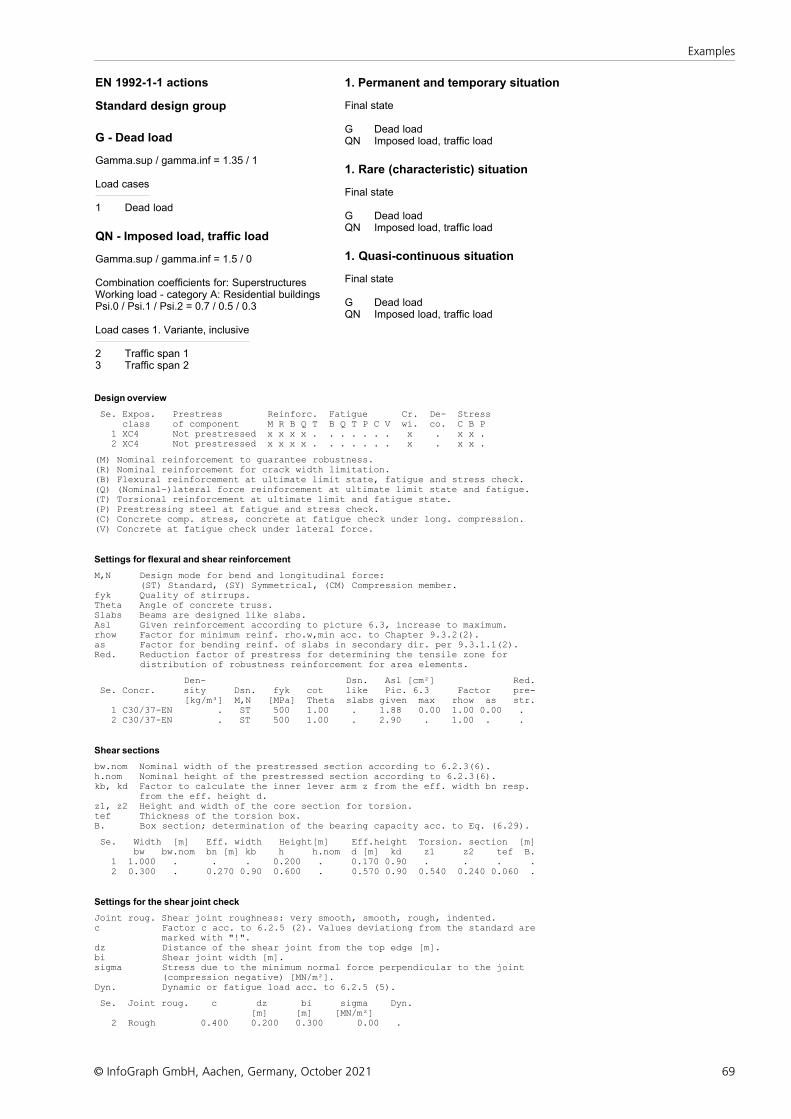
69
Examples
© InfoGraph GmbH, Aachen, Germany, October 2021
EN 1992-1-1 actions
Standard design group
G - Dead load
Gamma.sup / gamma.inf = 1.35 / 1
Load cases
1 Dead load
QN - Imposed load, traffic load
Gamma.sup / gamma.inf = 1.5 / 0
Combination coefficients for: SuperstructuresWorking load - category A: Residential buildingsPsi.0 / Psi.1 / Psi.2 = 0.7 / 0.5 / 0.3
Load cases 1. Variante, inclusive
2 Traffic span 13 Traffic span 2
1. Permanent and temporary situation
Final state
G Dead loadQN Imposed load, traffic load
1. Rare (characteristic) situation
Final state
G Dead loadQN Imposed load, traffic load
1. Quasi-continuous situation
Final state
G Dead loadQN Imposed load, traffic load
Design overview
Se. Expos. Prestress Reinforc. Fatigue Cr. De- Stress class of component M R B Q T B Q T P C V wi. co. C B P 1 XC4 Not prestressed x x x x . . . . . . . x . x x . 2 XC4 Not prestressed x x x x . . . . . . . x . x x .
(M) Nominal reinforcement to guarantee robustness.(R) Nominal reinforcement for crack width limitation.(B) Flexural reinforcement at ultimate limit state, fatigue and stress check.(Q) (Nominal-)lateral force reinforcement at ultimate limit state and fatigue.(T) Torsional reinforcement at ultimate limit and fatigue state.(P) Prestressing steel at fatigue and stress check.(C) Concrete comp. stress, concrete at fatigue check under long. compression.(V) Concrete at fatigue check under lateral force.
Settings for flexural and shear reinforcement
M,N Design mode for bend and longitudinal force: (ST) Standard, (SY) Symmetrical, (CM) Compression member.fyk Quality of stirrups.Theta Angle of concrete truss.Slabs Beams are designed like slabs.Asl Given reinforcement according to picture 6.3, increase to maximum.rhow Factor for minimum reinf. rho.w,min acc. to Chapter 9.3.2(2).as Factor for bending reinf. of slabs in secondary dir. per 9.3.1.1(2).Red. Reduction factor of prestress for determining the tensile zone for distribution of robustness reinforcement for area elements.
Den- Dsn. Asl [cm²] Red. Se. Concr. sity Dsn. fyk cot like Pic. 6.3 Factor pre- [kg/m³] M,N [MPa] Theta slabs given max rhow as str. 1 C30/37-EN . ST 500 1.00 . 1.88 0.00 1.00 0.00 . 2 C30/37-EN . ST 500 1.00 . 2.90 . 1.00 . .
Shear sections
bw.nom Nominal width of the prestressed section according to 6.2.3(6).h.nom Nominal height of the prestressed section according to 6.2.3(6).kb, kd Factor to calculate the inner lever arm z from the eff. width bn resp. from the eff. height d.z1, z2 Height and width of the core section for torsion.tef Thickness of the torsion box.B. Box section; determination of the bearing capacity acc. to Eq. (6.29).
Se. Width [m] Eff. width Height[m] Eff.height Torsion. section [m] bw bw.nom bn [m] kb h h.nom d [m] kd z1 z2 tef B. 1 1.000 . . . 0.200 . 0.170 0.90 . . . . 2 0.300 . 0.270 0.90 0.600 . 0.570 0.90 0.540 0.240 0.060 .
Settings for the shear joint check
Joint roug. Shear joint roughness: very smooth, smooth, rough, indented.c Factor c acc. to 6.2.5 (2). Values deviationg from the standard are marked with "!".dz Distance of the shear joint from the top edge [m].bi Shear joint width [m].sigma Stress due to the minimum normal force perpendicular to the joint (compression negative) [MN/m²].Dyn. Dynamic or fatigue load acc. to 6.2.5 (5).
Se. Joint roug. c dz bi sigma Dyn. [m] [m] [MN/m²] 2 Rough 0.400 0.200 0.300 0.00 .
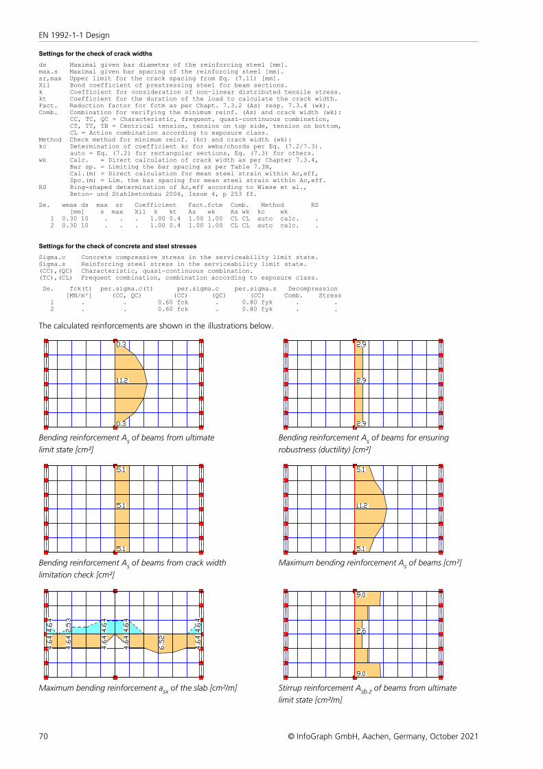
70
EN 1992-1-1 Design
© InfoGraph GmbH, Aachen, Germany, October 2021
Settings for the check of crack widths
ds Maximal given bar diameter of the reinforcing steel [mm].max.s Maximal given bar spacing of the reinforcing steel [mm].sr,max Upper limit for the crack spacing from Eq. (7.11) [mm].Xi1 Bond coefficient of prestressing steel for beam sections.k Coefficient for consideration of non-linear distributed tensile stress.kt Coefficient for the duration of the load to calculate the crack width.Fact. Reduction factor for fctm as per Chapt. 7.3.2 (As) resp. 7.3.4 (wk).Comb. Combination for verifying the minimum reinf. (As) and crack width (wk): CC, TC, QC = Characteristic, frequent, quasi-continuous combination, CT, TT, TB = Centrical tension, tension on top side, tension on bottom, CL = Action combination according to exposure class.Method Check method for minimum reinf. (kc) and crack width (wk):kc Determination of coefficient kc for webs/chords per Eq. (7.2/7.3). auto = Eq. (7.2) for rectangular sections, Eq. (7.3) for others.wk Calc. = Direct calculation of crack width as per Chapter 7.3.4, Bar sp. = Limiting the bar spacing as per Table 7.3N, Cal.(m) = Direct calculation for mean steel strain within Ac,eff, Spc.(m) = Lim. the bar spacing for mean steel strain within Ac,eff.RS Ring-shaped determination of Ac,eff according to Wiese et al., Beton- und Stahlbetonbau 2004, Issue 4, p 253 ff.
Se. wmax ds max sr Coefficient Fact.fctm Comb. Method RS [mm] s max Xi1 k kt As wk As wk kc wk 1 0.30 10 . . . 1.00 0.4 1.00 1.00 CL CL auto calc. . 2 0.30 10 . . . 1.00 0.4 1.00 1.00 CL CL auto calc. .
Settings for the check of concrete and steel stresses
Sigma.c Concrete compressive stress in the serviceability limit state.Sigma.s Reinforcing steel stress in the serviceability limit state.(CC),(QC) Characteristic, quasi-continuous combination.(TC),(CL) Frequent combination, combination according to exposure class.
Se. fck(t) per.sigma.c(t) per.sigma.c per.sigma.s Decompression [MN/m²] (CC, QC) (CC) (QC) (CC) Comb. Stress 1 . . 0.60 fck . 0.80 fyk . . 2 . . 0.60 fck . 0.80 fyk . .
The calculated reinforcements are shown in the illustrations below.
Bending reinforcement As of beams from ultimate
limit state [cm²]
Bending reinforcement As of beams for ensuring
robustness (ductility) [cm²]
Bending reinforcement As of beams from crack width
limitation check [cm²]
Maximum bending reinforcement As of beams [cm²]
Maximum bending reinforcement asx of the slab [cm²/m]
Stirrup reinforcement Asb.z of beams from ultimate
limit state [cm²/m]

71
Examples
© InfoGraph GmbH, Aachen, Germany, October 2021
Transverse reinforcement shear joint check Asb of beams
from ultimate limit state [cm²/m]
Stirrup reinforcement asb of the slab from ultimate limit
state [cm²/m²] (node mean values)
An excerpt of the detailed log for the midspan of the downstand beam is provided below.
Design of longitudinal reinforcement
The calculated requ. reinforcement includes the specified basic reinforcement.
(M) Nominal reinf. for robustness as per EN 1992-2, 6.1 (109) (Charact. C.) fctm Average centric concrete tensile strength [MN/m²] zs,t/b Lever arm of inner strengths top/bottom with zs=0,9*d [m] fyk,t/b Strength of longitudinal reinforcement top/bottom [MN/m²] max Sc Maximum concrete edge stress from Charact. C. [MN/m²](R) Nominal/requ. reinforcement as per 7.3.2 for crack width limitation Increase of reinforcement due to crack width check is marked by "!". wmax Permissible crack width as per specification [mm] ds Maximal given steel diameter [mm] k Coefficient for consideration of non-linear distributed tensile stress fct,eff Concrete strength at date of cracking [MN/m²] kc Coefficient to consider stress distribution in tensile zone acc. to Eq. (7.2) resp. Eq. (7.3) max Sx Maximal concrete edge stress from action combination [MN/m²](B) Design of reinforement at ultimate limit state In case of dominant bending, compression reinforcement is marked with "*". For section areas acc. to 6.1 (5) the conrecte strain is not limited. The minimum reinforcement acc. to 9.2.1.1 and 9.3.1.1 is not determined. For compressive members the minimum reinf. acc. to 9.5.2 is considered. fck Concrete strength for design of reinforcement [MN/m²]
Beam 70, x = 0.00 m (Beam length 0.83 m)Cross-section 2: Polygon - C30/37-ENSteel 2; Design mode: Standard(M) fctm=2.9; zs,t/b=0.513/0.513; fyk,t/b=500/500(R) wmax=0.3; ds=10; kc per Eq. (7.3); k=1; fct,eff=2.9(B) fck=30
Section properties A [m²] ys [m] zs [m] Iy [m4] Iz [m4] Iyz[m4] gross : 0.460 0.850 0.178 0.0107 0.0828 0.0000
1. Characteristic (rare) combination (CC.1): G+QN, Final state
Relevant concrete internal forces from 4 sets of internal forcesSet Nx[kN] My[kNm] Mz[kNm]1 : 0.00 69.95 0.002 : 0.00 196.53 0.00
Load case combinations for the relevant sets of internal forcesSet Combination1 : L12 : L1+L2+L3
1. Quasi-continuous combination (QC.1): G+QN, Final state
Relevant concrete internal forces from 4 sets of internal forcesSet Nx[kN] My[kNm] Mz[kNm]2 : 0.00 107.92 0.00
Load case combinations for the relevant sets of internal forcesSet Combination2 : L1+0.30*L2+0.30*L3
1. Permanent and temporary comb. (PC.1): G+QN, Final state
Relevant concrete internal forces from 8 sets of internal forcesSet Nx[kN] My[kNm] Mz[kNm]2 : 0.00 284.31 0.005 : 0.00 69.95 0.00
Load case combinations for the relevant sets of internal forcesSet Combination2 : 1.35*L1+1.50*L2+1.50*L35 : L1

72
EN 1992-1-1 Design
© InfoGraph GmbH, Aachen, Germany, October 2021
Design of longitudinal reinforcement
Reinforcement Nx My Mz max Sc kc Ap' req.As SituationLay. Type [kN] [kNm] [kNm] [MN/m²] [cm²] [cm²] 1 M 0.00 69.95 0.00 . . . 0.00 CC.1,1 R 0.00 107.92 0.00 4.25 . . 0.00 QC.1,2 B 0.00 69.95 0.00 . . . 0.00 PC.1,5 2 M 0.00 69.95 0.00 . . . 0.00 CC.1,1 R 0.00 107.92 0.00 4.25 . . 0.00 QC.1,2 B 0.00 69.95 0.00 . . . 0.00 PC.1,5 3 M 0.00 196.53 0.00 7.73 . . 1.44 CC.1,2 R 0.00 107.92 0.00 4.25 0.50 . 2.53 QC.1,2 B 0.00 284.31 0.00 . . . 5.60 PC.1,2 4 M 0.00 196.53 0.00 7.73 . . 1.44 CC.1,2 R 0.00 107.92 0.00 4.25 0.50 . 2.53 QC.1,2 B 0.00 284.31 0.00 . . . 5.60 PC.1,2
Design of shear reinforcement
The percentage of nominal reinforcement acc. to Eq. (9.5N) is considered.
Ac Section area for calculating the concrete stress from long. force [m²]bw Effective width for calculation of shear stresses from Qz and Mx [m]bn Statically effective width for shear design using Qy [m]kb Factor to calculate the inner lever arm from bnh Effective height for calculation of shear stresses from Qy and Mx [m]d Statically effective height for shear design using Qz [m]kd Factor to calculate the inner lever arm from dAngle Angle cot Theta between the compressive strut and the beam axisAsl giv. Chargeable longitudinal reinf. acc. to Fig. 6.3 [cm²]rhow,min Minimal percentage of lateral reinforcement acc. to Eq. (9.5N)Qy, Qz Lateral forces for design in y- and z-direction [kN]VRdc Absorbable lat. force without lat. reinf. per 6.2.2 (1) [kN]VRdmax Absorbable lateral force of comp. struts per 6.2.3 (3) [kN]z Inner lever arm z=kb*bn resp. z=kd*d [m]Asb.y,z Req. stirrup reinforcement from Qy resp. Qz [cm²/m]Asl Req. longitudinal reinf. acc. to Fig. 6.3 [cm²] for req.AsbDelta Ftd Tensile force in long. reinf. from lateral force as per Eq. (6.18)
Beam 70, x = 0.00 m (Beam length 0.83 m)Cross-section 2: Polygon - C30/37-ENbw/bn/kb=0.3/0.27/0.9; h/d/kd=0.6/0.57/0.9Ac=0.46; fyk=500; Asl giv./max=2.9/0; rhow,min=1*(0.08*fck½/fyk)
1. Permanent and temporary comb. (PC.1): G+QN, Final state
Relevant concrete internal forces from 8 sets of internal forcesSet Nx[kN] My[kNm] Mz[kNm] Mx[kNm] Qy[kN] Qz[kN]2 : 0.00 284.31 0.00 0.00 0.00 -30.79
Load case combinations for the relevant sets of internal forcesSet Combination2 : 1.35*L1+1.50*L2+1.50*L3
Check of the shear reinforcement and the compressive struts
Action z Q/ Asb.y Asb.z Asb.T Asl.T Aslmax [m] Angle VRdc [cm²/m] [cm²/m] [cm²/m] [cm²] [cm²] SituationQy : 0.24 1.00 0.00 . . . . . -,-Qz : 0.51 1.00 0.47 . 2.63 . . 2.90 PC.1,2
Action z Qy/ Qz/ Mx/ Q/VRd+ Delta Ftdmax [m] Angle VRdmax VRdmax TRdmax Mx/TRd [kN] SituationQy : 0.24 1.00 0.00 . . . 0.00 -,-Qz : 0.51 1.00 . 0.04 . . 15.40 PC.1,2
Shear joint check
bi Width of the joint [m]sigma.n Stress perpendicular to the joint acc. to user specifications. Negative for compression [MN/m²]Roughness Joint roughness (very smooth, smooth, rough, indented) c, mue Factors dependent on joint roughness according to 6.2.5(2)z Inner lever arm according to shear section [m]beta Ratio of longitudinal force in the new concrete and total longitudinal force in compression or tension zone. If the strain state cannot be clearly determined, 1.0 is assumed on the save side (marking *)vEdi Design value of shear stress in the joint acc. to Eq. (6.24) [MN/m²]vRdi Design value of shear resistance in the joint acc. to Eq. (6.25) [MN/m²]vEdi/vRdi Utilization ratereq. Asb Area of the required transverse reinforcement [cm²/m]
Beam 70, x = 0.00 m (Beam length 0.83 m)Cross-section 2: Polygon - C30/37-ENbi = 0.3 m; sigma.n = 0 MN/m²Roughness = Rough; c = 0.4; mue = 0.7
1. Permanent and temporary comb. (PC.1): G+QN, Final state
Relevant concrete internal forces from 8 sets of internal forcesSet Nx[kN] My[kNm] Mz[kNm] Qz[kN]2 : 0.00 284.31 0.00 -30.79
Load case combinations for the relevant sets of internal forcesSet Combination2 : 1.35*L1+1.50*L2+1.50*L3

73
Examples
© InfoGraph GmbH, Aachen, Germany, October 2021
Shear joint check
z beta vEdi vRdi vEdi/ req. Asb [m] [-] [MN/m²] [MN/m²] vRdi [cm²/m] Situation 0.51 1.00 0.2001 0.5413 0.37 0.00 PC.1,2
Check of crack widths
The check is led by direct calculation of the crack width.The final long. reinforcement as the maximum from robustness, crack and bendingreinf. incl. a possible increase resulting from the fatigue check is decisive.
(CC) Charact. (rare), (TC) Frequent, (QC) Quasi-continuous combination
wmax Permissible crack width as per specification [mm]ds Maximal given steel diameter [mm]fct,eff Concrete strength at date of cracking [MN/m²]Sigma.c Maximal concrete edge stress in state I [MN/m²]wk Calculated value of crack width as per 7.3.4 [mm]sr,max Calculated / given maximal crack spacing as per 7.3.4 (3) [mm]Ac,eff Effective region of reinf. [m²] acc. to Fig. 7.1As,eff Reinforcing steel within Ac,eff [cm²]Ap,eff Prestressing steel with bond within Ac,eff [cm²]Sigma.s Reinf. steel stress in state II [MN/m²]kt Coefficient for the duration of load as per 7.3.4 (2)
Beam 70, x = 0.00 m (Beam length 0.83 m)Cross-section 2: Polygon - C30/37-ENwmax=0.3; ds=10; fct,eff=2.9; kt=0.4
Section properties A [m²] ys [m] zs [m] Iy [m4] Iz [m4] Iyz[m4] gross : 0.460 0.850 0.178 0.0107 0.0828 0.0000
1. Quasi-continuous combination (QC.1): G+QN, Final state
Relevant concrete internal forces from 4 sets of internal forcesSet Nx[kN] My[kNm] Mz[kNm]2 : 0.00 107.92 0.00
Load case combinations for the relevant sets of internal forcesSet Combination2 : L1+0.30*L2+0.30*L3
Check of crack width for reinf. layer 3 (bottom)
Nx : 0.00 kN As,eff : 11.19 cm²My : 107.92 kNm Ap,eff : . cm²Mz : 0.00 kNm Ac,eff : 0.023 m²Sigma.c : 4.25 MN/m² Sigma.s : 175.61 MN/m²Situation : QC.1,2 sr,max : 119.17 mm wk : 0.09 wmax 0.30 mm
Check of concrete compressive stress
For the check, a cracked concrete section (II) is assumed if the tensile stressfrom the decisive c. exceeds the value of fctm. Otherwise, a non-cracked section(I) is used. If the strain is not absorbable on cracked section, (I*) is marked.
fck Characteristic compressive concrete strength [MN/m²]Sigma.x,min Total maximal longitudinal compressive stress [MN/m²]Sigma.x,per = 0,60*fck for Charact. C. (CC) as per 7.2 (2)top, bottom Position of the edge point: above, below of centre
Beam 70, x = 0.00 m (Beam length 0.83 m)Cross-section 2: Polygon - C30/37-EN0.6*fck=18
Section properties A [m²] ys [m] zs [m] Iy [m4] Iz [m4] Iyz[m4] gross : 0.460 0.850 0.178 0.0107 0.0828 0.0000
1. Characteristic (rare) combination (CC.1): G+QN, Final state
Relevant concrete internal forces from 4 sets of internal forcesSet Nx[kN] My[kNm] Mz[kNm]1 : 0.00 69.95 0.002 : 0.00 196.53 0.00
Load case combinations for the relevant sets of internal forcesSet Combination1 : L12 : L1+L2+L3
Check of compressive stress in concrete for the Characteristic (rare) combination
Side Se.- min Sigma.x per. Sigma.x Period Situation Pnt. [MN/m²] [MN/m²]top 1 (II) -6.58 -18.00 Final CC.1,2 bottom 7 (II) 0.00 -18.00 Final CC.1,1

74
EN 1992-1-1 Design
© InfoGraph GmbH, Aachen, Germany, October 2021
Check of steel stress
For the check, a cracked concrete section is assumed.
Type S Long. reinf. from N and M, layer number, Charact. C. (CC)fck Concrete strength to determine the strain state [MN/m²]Sigma.s,per = 0.80 * fyk resp. 1.0 * fyk (CK) as per 7.2 (5)
Beam 70, x = 0.00 m (Beam length 0.83 m)Cross-section 2: Polygon - C30/37-ENfck=30; Steel 2; 0.8*fyk,t/b=400/400
Section properties A [m²] ys [m] zs [m] Iy [m4] Iz [m4] Iyz[m4] gross : 0.460 0.850 0.178 0.0107 0.0828 0.0000
1. Characteristic (rare) combination (CC.1): G+QN, Final state
Relevant concrete internal forces from 4 sets of internal forcesSet Nx[kN] My[kNm] Mz[kNm]1 : 0.00 69.95 0.002 : 0.00 196.53 0.00
Load case combinations for the relevant sets of internal forcesSet Combination1 : L12 : L1+L2+L3
Check of steel stress
Steel Nx My Mz As Sigma.s per. SituationType No. [kN] [kNm] [kNm] [cm²] [MN/m²] [MN/m²] S 1 0.00 69.95 0.00 0.00 . 400.00 CC.1,1 S 2 0.00 69.95 0.00 0.00 . 400.00 CC.1,1 S 3 0.00 196.53 0.00 5.60 319.92 400.00 CC.1,2 S 4 0.00 196.53 0.00 5.60 319.92 400.00 CC.1,2
Flat Ceiling With CantileverThis example is a ceiling slab corresponding to Example 18 in the book 'Beispiele zur Bemessung nach Eurocode 2 – Band 2:Ingenieurbau'. The hinged slab is loaded with permanent loads and a traffic load applied span by span. The load cases arecalculated linearly-elastically, combined to minimum and maximum design internal forces according to the permanent andtemporary design situations and designed for the ultimate limit state. Furthermore, elastic calculations are performed for adeformation check.
The vertical spring stiffnesses Cz of the walls and columns are applied according to the literature.
5.405.406.20 2.65
8.2
0
13
.70
5.5
0
19.65
2.3070705.056.20 4.70
50
2.0
570
4.6
55
.80
1
2
4
3
A B C D E
45 45 45 45
CC = 2214 MN/m
= 2186.67 MN/m²z
z
Reinforcing steel: B500A
Concrete: C30/37 acc. to EN 1992-1-1
Columns:
Ceiling height: 26 cm
Mesh width: 35 cm
Walls:
Element system with dimensions [m]

75
Examples
© InfoGraph GmbH, Aachen, Germany, October 2021
Design according to EN 1992-1-1
Loads
Load case 1, G permanent load [kN/m²]
Load case 2 to 9, Q field 1 to 8 [kN/m²]
Reinforcement for area elements
No. Lay. Qual. d1x d2x asx d1y d2y asy as Roll-[m] [m] [cm²/m] [m] [m] [cm²/m] fix ing
1 1 500M 0.045 0.000 0.035 0.000 Warm2 500M 0.035 0.000 0.025 0.000 Warm
as Base reinforcement d1 Distance from the upper edge d2 Distance from the lower edge
The z axis of the element system points to the lower edge
Bending reinforcement from design of the permanent and temporary situation
Bending reinforcement upper layer asx.1 [cm²/m]
Bending reinforcement lower layer asx.2 [cm²/m]
Bending reinforcement upper layer asy.1 [cm²/m]
0.01
1.88
3.35
4.24
5.65
7.85
11.34
Bending reinforcement lower layer asy.2 [cm²/m]

76
EN 1992-1-1 Design
© InfoGraph GmbH, Aachen, Germany, October 2021
Deformation uz
The combination coefficient y2 of the quasi-continuous situation is assumed to be 0.3 in this example. For the calculation
of the creep deformation a creep-generating permanent load case has to be defined (here superposition load casenumber 11).
Load data load case 11: G+0.3·Q with elastic material behavior
Superposition of results (SUP)load case weighting
No. from to
1 1 1 1.000 2 2 9 0.300
The concrete creep is then calculated in load case 12 (load type Creep and shrinkage). In addition to the data in the loadcase, the creep and shrinkage coefficients of the concrete material specified in the cross-section are required. Since theshrinkage coefficient has no meaning for slab elements, it was set to zero in this example.Alternatively, the coefficientscould have been calculated via the dialog according to the formulas of the standard.
The internal forces due to creepwere not taken into account inthe design, since they generallyremain insignificant for allelements with identical creepcoefficients. However, relevantdeformations due to creep areto be expected.
Below are some of the results.
-3.00
0.00
3.00
6.00
9.00
12.00
15.00
18.00
21.00
24.00
27.00
Load case 11 (G+0.3·Q): Color gradient of the deformations uz [mm] at the start of loading

77
Examples
© InfoGraph GmbH, Aachen, Germany, October 2021
-3.00
0.00
3.00
6.00
9.00
12.00
15.00
18.00
21.00
24.00
27.00
Load case 13: Color gradient of the deformations uz [mm] at time t¥
In summary, the following maximum deformations result in state I:
max uz [mm]
Load case Calculation Literature
11 G+0.3·Q with elastic material behavior 10 10
12 Creeping (j=2,5 by LC 11) with elastic material behavior 23
13 Total (load case 11 + load case 12) 33
Principal tensile stresses s1
-6.00
-5.00
-4.00
-3.00
-2.00
-1.00
0.00
1.00
2.00
2.90
3.90
Load case 13: Color gradient of the principal tensile stresses s1,bottom and s1,top [MN/m²]
If Since the principal tensile stresses s1 exceed the concrete tensile strength fctm of 2.9 MN/m in a large area, the calculation
in state I is not suitable for the deformation check. In the manual section for the nonlinear system analysis, the deformationsare therefore examined in detail in state II for this example.

78
EN 1992-1-1 Design
© InfoGraph GmbH, Aachen, Germany, October 2021
Flat Ceiling With Cantilever and PrestressingThis example is a variant of the previous example with prestressing without bond. For comparison, the required concretereinforcement according to EN 1992-1-1 and the linear-elastic deformations are also determined. The prestressing isprimarily intended to reduce the deflection of the slab.
Since a prestressed slab also results in normal forces in the area, shell elements must be used and care must be taken toensure that the horizontal supports are as free of restraints as possible. Otherwise, large tensile stresses would result fromthe shrinkage of the concrete.
Monostrands of 7-strand prestressing steel St 1570/1770 with a corrosion protection system in free tendon position areused. The 50 tendons (1) in y-direction are uniformly distributed single monostrands. The four tendons (2) in the x-directionare double bundled monostrands.
311 49x0.36=17.641.7
3x0
.30
=0
.90
19.6514.3914.218.998.81
zv
<
|
17.9811.606.203.590.00xv
101
17.001.67
2 Superelevation = 5
Tendon group ordinates zv [cm] at the base points
0.0-8.08.08.08.08.0-8.08.00.0 -8.0-8.08.0
1
Su
pe
rele
vatio
n =
5
Ten
do
n g
rou
p o
rdin
ate
s z
v [c
m]
at
the
ba
se
po
ints
00
2
pkf = 1770 MN/m²fp0,1k
Æ
= 202.5 kN (1 stand)maxPPm0
SUSPA/DSI-Monostrand SVM
Stand: 15,7 mm, Ap = 150 mm²
Anchorage SKM/MGS, Anchor slip: 6 mm
= 1500 MN/m²,
= 191.25 kN,
zvxv
9.0
1.7
2
0.0
13.7
0
0.0
0.0
00
5.0
3
9.0
8.6
5
-10.0
10.9
7
0.0
7.7
5
-10.0
System with arrangement of monostrands in free tendon position with their high and low points
Loads
In addition to the load cases of the previous example, a prestressing load case (load type Prestressing) is required.The creep-generating permanent load case 11 is supplemented by the prestressing load case. Since the tendons have no bond with
the concrete, the shrinkage of the concrete of es,¥ = -40·10-5 assumed in the literature leads to an additional anchor slip of
7.9 mm in x direction and 5.5 mm in y direction. Thus, at time t¥, neglecting friction, a prestressing force of 178 kN per
tendon (1) and 359 kN per tendon (2) results. The prestressing at an earlier time is not investigated in this example.
Load data load case 10: P prestressing
No.
1 Prestressing (VSPG)
Load data load case 11: G+P+0.3·Q with elastic material behavior
Superposition of results (SUP)load case weighting
No. from to
1 1 1 1.000 2 10 10 1.000 3 2 9 0.300

79
Examples
© InfoGraph GmbH, Aachen, Germany, October 2021
Design according to EN 1992-1-1
The design-relevant actions are supplemented by the prestressing and the creep load case.
EN 1992-1-1 actions
Standard design group
QN - Imposed load, traffic load
Gamma.sup / gamma.inf = 1.5 / 0
Combination coefficients for: Superstructures Working load - category A: Residential buildings Psi.0 / Psi.1 / Psi.2 = 0.7 / 0.5 / 0.3
Load cases 1. Variant, inclusive
2 Q field 13 Q field 24 Q field 35 Q field 46 Q field 57 Q field 68 Q field 79 Q field 8
G - Dead load
Gamma.sup / gamma.inf = 1.35 / 1
Load cases
1 G permanant load
P - Prestressing
Gamma.sup / gamma.inf = 1 / 1
Load cases internal prestressing
10 P prestressing
CSR1 - Creep, shrinkage, relaxation
Load cases
12 Creeping (φ=2.5 by LC 11) with elastic material beh...
1. Permanent and temporary situation
Final state
G Dead loadP PrestressingCSR1 Creep, shrinkage, relaxationQN Imposed load, traffic load
Bending reinforcement from design of the permanent and temporary situation
Bending reinforcement upper layer asx.1 [cm²/m]
Bending reinforcement lower layer asx.2 [cm²/m]
Bending reinforcement upper layer asy.1 [cm²/m]
0.01
1.88
3.35
4.24
5.65
7.85
11.34
Bending reinforcement lower layer asy.2 [cm²/m]

80
EN 1992-1-1 Design
© InfoGraph GmbH, Aachen, Germany, October 2021
Deformation uz
-1.00
0.00
1.00
2.00
3.00
4.00
5.00
6.00
7.00
8.00
9.00
10.00
Load case 13: Color gradient of the deformations uz [mm] at time t¥
In summary, the following maximum deformations result in state I compared to the previous example without prestressing:
max uz [mm]
Load case with prestress without prestress
11 G+P+0.3·Q with elastic material behavior 3 10
12 Creeping (j=2,5 by LC 11) with elastic material behavior 5 23
13 Total (load case 10 + load case 11) 8 33
Principal tensile stresses s1
-6.00
-5.00
-4.00
-3.00
-2.00
-1.00
0.00
1.00
2.00
2.90
3.90
Load case 13: Color gradient of the principal tensile stresses s1,bottom and s1,top [MN/m²]
Since the principal tensile stresses s1 exceed the concrete tensile strength fctm of 2.9 MN/m² only in small areas, an
investigation in state II is not performed.

81
Examples
© InfoGraph GmbH, Aachen, Germany, October 2021
Prestressed Roof ConstructionThis example involves the wide-spanned roof construction of an entrance hall that is represented as a continuous girder overtwo spans with a double-sided cantilever. A T-beam is selected as the section. The figure below shows the system inlongitudinal and lateral section view.
Limited prestressing with subsequent bond is applied to the roof construction in the longitudinal direction. Prestressing inthe lateral direction is not applied for reasons of economy. The construction is designed to meet exposure class XC1.According to Table 7.1N of the EN 1992-1-1, a decompression check is not necessary for this class.
Finite Elemente 7.00a © InfoGraph GmbH H_EN1992_VDach.fem - 03.03.2008 12:27:44 - Blatt 1
InfoGraph GmbH, Kackertstr. 10, D-52072 Aachen, Tel. (0241) 889980
M = 1:1077
Static system and dimensions (longitudinal and lateral section)
Material
Concrete C45/55-EN
Reinforcing steel BSt 500, axis distance from edge 5 cm
Section
Prestressing steel and prestressing system
Prestressing steel quality St 1500/1770
Certification of the prestressing system EC2
Number of tendons in the bundle 4
Section surface Ap 1800 mm²
E-modulus of the prestressing steel 195000 MN/m²
0.1% strain limit (yield strength) of the prestressing steel fp0.1k 1500 MN/m²
Tensile strength of the prestressing steel fpk 1770 MN/m²
Permissible prestressing force of a tendon Pm0 2295 kN
Prestressing loss from relaxation of prestressed steel 4.5 %
Friction coefficients when prestressing and releasing m 0.2
Unintentional deviation angle of a tendon ß’ 0.3 °/m
Slippage at prestressing anchor 6 mm
Duct diameter dh 82 mm
Variation coefficients of the internal prestressing
Construction stage (rsup / rinf ) 1.1 / 0.9
Final state (rsup / rinf ) 1.1 / 0.9

82
EN 1992-1-1 Design
© InfoGraph GmbH, Aachen, Germany, October 2021
The tendon guide is shown in the next figure. 4 bundled tendons are arranged such that they stretch across the entiregirder length and are prestressed at both girder ends. The prestressing system, prestressing procedure and prestressingcurve for a tendon group are also shown.
00
Tendon groups in beam series view 1, [-16.00/0.00/0.00] - [112.00/0.00/0.00] / [-16.00/0.00/1.00]Superelevation = 10
Tendon group ordinates zv [cm] at the base points
xv 0.00 6.40 12.80 19.20 25.60 32.00 38.40 44.80 51.20 57.60 64.00 70.40 76.80 83.20 89.60 96.00 102.40 108.80 115.20 121.60 128.00
1 70.0 52.0 19.2 42.0 120.2 180.1 208.8 201.5 157.4 78.3 18.5 78.3 157.4 201.5 208.8 180.1 120.2 42.0 19.2 52.0 70.0
Force function of tendon group 1 (4 tendon(s), l = 128.41 m)
Prestressing system 1 - Example. Certification according to EC2.Pm0 = 2295.0 kN, Ap = 1800.0 mm², µa = 0.20, Angle ß' = 0.30 °/mE-Modulus= 195000 MN/m², Ah = 5281.0 mm², µn = 0.20, Slippage = 6.00 mm
Prestressing procedure 1 - Example
Pre. anchor : Start EndNormal. force : 1.000 1.000Pre. force [kN]: 2295.0 2295.0Extension [mm]: 694.5 72.8
8717.5
xv
[m]0.00
8337.3
[kN
]
6.40
8452.6
12.80
8584.5
19.20
8623.2
25.60
8506.5
32.00
8373.7
38.40
8229.0
44.80
8079.4
51.20
7936.2
57.60
7814.6
64.00
7556.0
70.40
7814.6
76.80
7936.2
83.20
8079.4
89.60
8229.0
96.00
8373.7
102.40
8506.5
108.80
8623.2
115.20
8584.5
121.60
8452.6
128.00
8337.3
Tendon guide and prestressing curve in the longitudinal section (4 tendons).
Loads
Load case 1 Dead load
Load case 2 Additional dead load: q=11.06 kN/m
Load case 3 Snow load: q=7.90 kN/m
Load case 10 Prestressing
Load case 15 Creep-generating permanent load: Dead load, additional dead load and prestressing
Load case 20 Creep and shrinkage
Coefficients: jt¥ = 2.55; r = 0.8; et¥ = -24.8 · 10-5
Creep-generating permanent load case: 15The redistribution of internal forces between concrete and prestressing steel are taken into account.

83
Examples
© InfoGraph GmbH, Aachen, Germany, October 2021
EN 1992-1-1 actions
Standard design group
G - Dead load
Gamma.sup / gamma.inf = 1.35 / 1
Load cases
1 Dead load
G - Additional dead load
Gamma.sup / gamma.inf = 1.35 / 1
Load cases
2 Additional dead load
P - Prestressing
Gamma.sup / gamma.inf = 1 / 1
Load cases internal prestressing
10 Prestressing
CSR1 - Creep, shrinkage, relaxation
Prestressing loss from relaxation of prestressed steel: 4.5 %.
Load cases
20 Creep, shrinkage
QS - Snow and ice load
Gamma.sup / gamma.inf = 1.5 / 0
Combination coefficients for: SuperstructuresSnow load - Places in CEN member states with more than 1000 m above sea levelPsi.0 / Psi.1 / Psi.2 = 0.7 / 0.5 / 0.2
Load cases 1. Variante, inclusive
3 Snow load
In this example all possible combinations of load cases are generated and designed. This method is selected in thecalculation settings and can be very slow when applied for a large number of load cases.
Below you will find an example of the curve of bending moment My for design situations in the ultimate limit states.
1. Permanent and temporary situation - Structural cond.
Construction stage - Ungrouted
G Dead loadP Prestressing
Bending moment My [kNm]
2. Permanent and temporary situation - t0
Final state
G Dead loadG Additional dead loadP PrestressingQS Snow and ice load
Bending moment My [kNm]

84
EN 1992-1-1 Design
© InfoGraph GmbH, Aachen, Germany, October 2021
3. Permanent and temporary situation - too
Final state
G Dead loadG Additional dead loadP PrestressingCSR1Creep, shrinkage, relaxationQS Snow and ice load
Bending moment My [kNm]
Design overview Se. Expos. Prestress Reinforc. Fatigue Cr. De- Stress class of component M R B Q T B Q T P C V wi. co. C B P 1 XC4 Subsequent bond x x x x . . . . . . . x . x x x (M) Nominal reinforcement to guarantee robustness.(R) Nominal reinforcement for crack width limitation.(B) Flexural reinforcement at ultimate limit state, fatigue and stress check.(Q) (Nominal-)lateral force reinforcement at ultimate limit state and fatigue.(T) Torsional reinforcement at ultimate limit and fatigue state.(P) Prestressing steel at fatigue and stress check.(C) Concrete comp. stress, concrete at fatigue check under long. compression.(V) Concrete at fatigue check under lateral force.
Dispersion of prestressing The variation of prestressing is considered at the following checks:- Check of decompression and concrete compressive stress- Nominal reinforcement for crack width limitation- Check of crack widthAll other checks are made using the mean value Pm,t of prestressing. Se. Prestressing of Const.period Final state component r.sup r.inf r.sup r.inf 1 Subsequent bond 1.10 0.90 1.10 0.90
Settings for flexural and shear reinforcement M,N Design mode for bend and longitudinal force: (ST) Standard, (SY) Symmetrical, (CM) Compression member.fyk Quality of stirrups.Theta Angle of concrete truss.Slabs Beams are designed like slabs.Asl Given reinforcement according to picture 6.3, increase to maximum.rhow Factor for minimum reinf. rho.w,min acc. to Chapter 9.3.2(2).as Factor for bending reinf. of slabs in secondary dir. per 9.3.1.1(2).Red. Reduction factor of prestress for determining the tensile zone for distribution of robustness reinforcement for area elements. Den- Dsn. Asl [cm²] Red. Se. Concr. sity Dsn. fyk cot like Pic. 6.3 Factor pre- [kg/m³] M,N [MPa] Theta slabs given max rhow as str. 1 C45/55-EN . ST 500 2.50 . 0.00 . 1.00 . .
Shear sections bw.nom Nominal width of the prestressed section according to 6.2.3(6).h.nom Nominal height of the prestressed section according to 6.2.3(6).kb, kd Factor to calculate the inner lever arm z from the eff. width bn resp. from the eff. height d.z1, z2 Height and width of the core section for torsion.tef Thickness of the torsion box.B. Box section; determination of the bearing capacity acc. to Eq. (6.29). Se. Width [m] Eff. width Height[m] Eff.height Torsion. section [m] bw bw.nom bn [m] kb h h.nom d [m] kd z1 z2 tef B. 1 0.500 0.500 0.450 0.90 2.300 2.300 2.250 0.90 2.200 0.400 0.100 .
Settings for the check of crack widths ds Maximal given bar diameter of the reinforcing steel [mm].max.s Maximal given bar spacing of the reinforcing steel [mm].sr,max Upper limit for the crack spacing from Eq. (7.11) [mm].Xi1 Bond coefficient of prestressing steel for beam sections.k Coefficient for consideration of non-linear distributed tensile stress.kt Coefficient for the duration of the load to calculate the crack width.Fact. Reduction factor for fctm as per Chapt. 7.3.2 (As) resp. 7.3.4 (wk).Comb. Combination for verifying the minimum reinf. (As) and crack width (wk): CC, TC, QC = Characteristic, frequent, quasi-continuous combination, CT, TT, TB = Centrical tension, tension on top side, tension on bottom, CL = Action combination according to exposure class.

85
Examples
© InfoGraph GmbH, Aachen, Germany, October 2021
Method Check method for minimum reinf. (kc) and crack width (wk):kc Determination of coefficient kc for webs/chords per Eq. (7.2/7.3). auto = Eq. (7.2) for rectangular sections, Eq. (7.3) for others.wk Calc. = Direct calculation of crack width as per Chapter 7.3.4, Bar sp. = Limiting the bar spacing as per Table 7.3N, Cal.(m) = Direct calculation for mean steel strain within Ac,eff, Spc.(m) = Lim. the bar spacing for mean steel strain within Ac,eff.RS Ring-shaped determination of Ac,eff according to Wiese et al., Beton- und Stahlbetonbau 2004, Issue 4, p 253 ff. Se. wmax ds max sr Coefficient Fact.fctm Comb. Method RS [mm] s max Xi1 k kt As wk As wk kc wk 1 0.20 20 . . 0.38 0.65 0.4 1.00 1.00 CL CL auto calc. .
Settings for the check of concrete and steel stresses fck(t) Compressive strength of concrete at the time t of prestressing.Sigma.c(t) Concrete compressive stress at the time t of prestressing.Sigma.c Concrete compressive stress in the serviceability limit state.Sigma.s Reinforcing steel stress in the serviceability limit state.(CC),(QC) Characteristic, quasi-continuous combination.(TC),(CL) Frequent combination, combination according to exposure class. Se. fck(t) per.sigma.c(t) per.sigma.c per.sigma.s Decompression [MN/m²] (CC, QC) (CC) (QC) (CC) Comb. Stress 1 45.00 0.45 fck(t) 0.60 fck . 0.80 fyk . .
The following illustration shows the curve of the required bending and shear reinforcement.
Longitudinal reinforcement As from the design in the ultimate limit states [cm²] (upper reinforcement with dashed lines).
Minimum reinforcement As for ensuring robustness (ductility) [cm²] (upper reinforcement with dashed lines).
Reinforcement As for limiting the crack width [cm²] (upper reinforcement with dashed lines).
Enclosing reinforcement As from the checks [cm²] (upper reinforcement with dashed lines).
(Minimum) lateral force reinforcement Asb,z in the ultimate limit states [cm²/m].
The following pages contain excerpts from the detailed check log for beam 16 at location 2 (middle column).
Design of longitudinal reinforcement The calculated requ. reinforcement includes the specified basic reinforcement. (M) Nominal reinf. for robustness as per EN 1992-2, 6.1 (109) (Charact. C.) fctm Average centric concrete tensile strength [MN/m²] zs,t/b Lever arm of inner strengths top/bottom with zs=0,9*d [m] fyk,t/b Strength of longitudinal reinforcement top/bottom [MN/m²] max Sc Maximum concrete edge stress from Charact. C. [MN/m²] without the statically determined part of prestressing(R) Nominal/requ. reinforcement as per 7.3.2 for crack width limitation Increase of reinforcement due to crack width check is marked by "!". wmax Permissible crack width as per specification [mm] ds Maximal given steel diameter [mm] k Coefficient for consideration of non-linear distributed tensile stress fct,eff Concrete strength at date of cracking [MN/m²] kc Coefficient to consider stress distribution in tensile zone acc. to Eq. (7.2) resp. Eq. (7.3) Ap' Part of prestr. steel area Xi1*Ap which was used to reduce req.As Xi1 Bond coefficient for prestressing steel as per Eq. (7.5) max Sx Maximal concrete edge stress from action combination [MN/m²]

86
EN 1992-1-1 Design
© InfoGraph GmbH, Aachen, Germany, October 2021
(B) Design of reinforement at ultimate limit state In case of dominant bending, compression reinforcement is marked with "*". For section areas acc. to 6.1 (5) the conrecte strain is not limited. The minimum reinforcement acc. to 9.2.1.1 and 9.3.1.1 is not determined. For compressive members the minimum reinf. acc. to 9.5.2 is considered. fck Concrete strength for design of reinforcement [MN/m²] N0, M0 Statically determined forces of tendons with bond [kN, kNm] fp0.1k Charact. value of the 0.1% strain limit of the prestr. steel [MN/m²] fpk Charact. value of the tensile strength of the prestr. steel [MN/m²]
Beam 16, x = 4.00 m (Beam length 4.00 m)Cross-section 1: Polygon - C45/55-EN, 1 tendon group with bondSteel 1; Design mode: Standard(M) fctm=3.8; zs,t/b=2.025/2.025; fyk,t/b=500/500(R) wmax=0.2; ds=20; kc per Eq. (7.3); k=0.65; fct,eff=3.8; Xi1=0.384 r.sup/inf(Constr.)=1.1/0.9; r.sup/inf(Final)=1.1/0.9(B) fck=45 Section properties A [m²] ys [m] zs [m] Iy [m4] Iz [m4] Iyz[m4] gross : 2.926 3.950 0.525 1.2560 9.8822 0.0000 net : 2.905 3.950 0.527 1.2535 9.8822 0.0000 ideally: 2.958 3.950 0.521 1.2596 9.8822 0.0000
Tendon groups with bond No. E-Modul fp0,1k fpk y z Ap Duct Prestress Inclin. [MN/m²] [MN/m²] [MN/m²] [m] [m] [mm²] d [mm] [kN] [°] 1 195000 1500 1770 3.950 0.185 7200 82 7555.99 0.00
1. Characteristic (rare) combination (CC.1): G.1+P, Construction stage ungrouted Relevant concrete internal forces from 1 sets of internal forcesSet Nx[kN] My[kNm] Mz[kNm]1 : -7555.93 -4040.19 0.00 Load case combinations for the relevant sets of internal forcesSet Combination1 : L1+L10
2. Characteristic (rare) combination (CC.2): G.1+G.2+P+QS, Final state grouted No set of internal forces in this situation was relevant.
3. Characteristic (rare) combination (CC.3): G.1+G.2+P+CSR1+QS, Final state grouted Loss of prestress by CSR in tendon groups No. CSR[%] No. CSR[%] No. CSR[%] No. CSR[%] No. CSR[%] 1 9.69 -.- -.- -.- -.- Stat. determ. part (P+CSR): Nx0=-6823.71 kN; My0=2320.06; Mz0=0.00 kNm Relevant values from 2 sets of internal forces Concrete section Bond sectionSet Nx[kN] My[kNm] Mz[kNm] Nx[kN] My[kNm] Mz[kNm]2 : -6714.14 -9384.61 0.00 109.56 -11704.67 0.00 Load case combinations for the relevant sets of internal forcesSet Combination2 : L1+L2+0.96*L10+L20+L3
1. Frequent combination (TC.1): G.1+P, Construction stage ungrouted No set of internal forces in this situation was relevant.
2. Frequent combination (TC.2): G.1+G.2+P+QS, Final state grouted No set of internal forces in this situation was relevant.
3. Frequent combination (TC.3): G.1+G.2+P+CSR1+QS, Final state grouted Relevant concrete internal forces from 4 sets of internal forcesSet Nx[kN] My[kNm] Mz[kNm]2 : -6042.73 -9624.61 0.00 r.inf Load case combinations for the relevant sets of internal forcesSet Combination2 : L1+L2+0.96*L10+L20+0.50*L3
1. Permanent and temporary comb. (PC.1): G.1+P, Construction stage ungrouted Relevant concrete internal forces from 2 sets of internal forcesSet Nx[kN] My[kNm] Mz[kNm]2 : -7555.93 -4040.19 0.00 Load case combinations for the relevant sets of internal forcesSet Combination2 : L1+L10
2. Permanent and temporary comb. (PC.2): G.1+G.2+P+QS, Final state grouted No set of internal forces in this situation was relevant.
3. Permanent and temporary comb. (PC.3): G.1+G.2+P+CSR1+QS, Final state grouted Loss of prestress by CSR in tendon groups No. CSR[%] No. CSR[%] No. CSR[%] No. CSR[%] No. CSR[%] 1 9.69 -.- -.- -.- -.- Stat. determ. part (P+CSR): Nx0=-6823.71 kN; My0=2320.06; Mz0=0.00 kNm

87
Examples
© InfoGraph GmbH, Aachen, Germany, October 2021
Relevant values from 8 sets of internal forces Concrete section Bond sectionSet Nx[kN] My[kNm] Mz[kNm] Nx[kN] My[kNm] Mz[kNm]2 : -6714.14 -16871.48 0.00 109.56 -19191.54 0.00 Load case combinations for the relevant sets of internal forcesSet Combination2 : 1.35*L1+1.35*L2+0.96*L10+L20+1.50*L3
Design of longitudinal reinforcement Charact. c.: max Sc = 1.63 < 3.80 MN/m² => no minimum crack reinf. required Reinforcement Nx My Mz max Sc kc Ap' req.As SituationLay. Type [kN] [kNm] [kNm] [MN/m²] [cm²] [cm²] 1 M 109.56 -11704.67 0.00 4.93 . . 44.91 CC.3,2 R -6042.73 -9624.61 0.00 . . . 25.28! TC.3,2 B -6714.14 -16871.48 0.00 . . . 18.11 PC.3,2 2 M 109.56 -11704.67 0.00 4.93 . . 44.91 CC.3,2 R -6042.73 -9624.61 0.00 . . . 25.28! TC.3,2 B -6714.14 -16871.48 0.00 . . . 18.11 PC.3,2 3 M 0.06 -6609.23 0.00 . . . 0.00 CC.1,1 R 0.00 0.00 0.00 0.00 . . 0.00 -,- B -7555.93 -4040.19 0.00 . . . 0.00 PC.1,2 4 M 0.06 -6609.23 0.00 . . . 0.00 CC.1,1 R 0.00 0.00 0.00 0.00 . . 0.00 -,- B -7555.93 -4040.19 0.00 . . . 0.00 PC.1,2
Design of shear reinforcement The percentage of nominal reinforcement acc. to Equ. (9.5N) is considered. Ac Section area for calculating the concrete stress from long. force [m²]bw Effective width for calculation of shear stresses from Qz and Mx [m]bw.nom Nominal value of the width when deducting the duct diameter [m]bn Statically effective width for shear design using Qy [m]kb Factor to calculate the inner lever arm from bnh Effective height for calculation of shear stresses from Qy and Mx [m]h.nom Nominal value of the height when deducting the duct diameter [m]d Statically effective height for shear design using Qz [m]kd Factor to calculate the inner lever arm from dAngle Angle cot Theta between the compressive strut and the beam axisAsl giv. Chargeable longitudinal reinf. acc. to Fig. 6.3 [cm²]rhow,min Minimal percentage of lateral reinforcement acc. to Eq. (9.5N)Qy, Qz Lateral forces for design in y- and z-direction [kN]VRdc Absorbable lat. force without lat. reinf. per 6.2.2 (1) [kN]VRdmax Absorbable lateral force of comp. struts per 6.2.3 (3) [kN]z Inner lever arm z=kb*bn resp. z=kd*d [m]Asb.y,z Req. stirrup reinforcement from Qy resp. Qz [cm²/m]Asl Req. longitudinal reinf. acc. to Fig. 6.3 [cm²] for req.AsbDelta Ftd Tensile force in long. reinf. from lateral force as per Eq. (6.18)
Beam 16, x = 4.00 m (Beam length 4.00 m)Cross-section 1: Polygon - C45/55-EN, 1 tendon group with bondbw/bw.nom/bn/kb=0.5/0.5/0.45/0.9; h/h.nom/d/kd=2.3/2.3/2.25/0.9Ac=2.926; fyk=500; Asl giv./max=0/0; rhow,min=1*(0.08*fck½/fyk)
1. Permanent and temporary comb. (PC.1): G.1+P, Construction stage ungrouted No set of internal forces in this situation was relevant.
2. Permanent and temporary comb. (PC.2): G.1+G.2+P+QS, Final state grouted Relevant concrete internal forces from 8 sets of internal forcesSet Nx[kN] My[kNm] Mz[kNm] Mx[kNm] Qy[kN] Qz[kN]2 : -7555.93 -15774.10 0.00 0.00 0.00 -3029.62 Load case combinations for the relevant sets of internal forcesSet Combination2 : 1.35*L1+1.35*L2+L10+1.50*L3
3. Permanent and temporary comb. (PC.3): G.1+G.2+P+CSR1+QS, Final state grouted Relevant concrete internal forces from 8 sets of internal forcesSet Nx[kN] My[kNm] Mz[kNm] Mx[kNm] Qy[kN] Qz[kN]2 : -6714.14 -16871.48 0.00 0.00 0.00 -3073.60 Load case combinations for the relevant sets of internal forcesSet Combination2 : 1.35*L1+1.35*L2+0.96*L10+L20+1.50*L3
Check of the shear reinforcement and the compressive struts Action z Q/ Asb.y Asb.z Asb.T Asl.T Aslmax [m] Angle VRdc [cm²/m] [cm²/m] [cm²/m] [cm²] [cm²] SituationQy : 0.41 2.50 0.00 . . . . . PC.2,2Qz : 2.02 2.50 3.95 . 13.96 . . 0.00 PC.3,2 Action z Qy/ Qz/ Mx/ Q/VRd+ Delta Ftdmax [m] Angle VRdmax VRdmax TRdmax Mx/TRd [kN] SituationQy : 0.41 2.50 0.00 . . . 0.00 PC.2,2Qz : 2.02 2.50 . 0.55 . . 3842.00 PC.3,2

88
EN 1992-1-1 Design
© InfoGraph GmbH, Aachen, Germany, October 2021
Check of crack widths The check is led by direct calculation of the crack width.The final long. reinforcement as the maximum from robustness, crack and bendingreinf. incl. a possible increase resulting from the fatigue check is decisive. (CC) Charact. (rare), (TC) Frequent, (QC) Quasi-continuous combination wmax Permissible crack width as per specification [mm]ds Maximal given steel diameter [mm]fct,eff Concrete strength at date of cracking [MN/m²]Sigma.c Maximal concrete edge stress in state I [MN/m²]wk Calculated value of crack width as per 7.3.4 [mm]sr,max Calculated / given maximal crack spacing as per 7.3.4 (3) [mm]Ac,eff Effective region of reinf. [m²] acc. to Fig. 7.1As,eff Reinforcing steel within Ac,eff [cm²]Ap,eff Prestressing steel with bond within Ac,eff [cm²]Sigma.s Reinf. steel stress in state II [MN/m²]kt Coefficient for the duration of load as per 7.3.4 (2)Xi1 Bond coefficient for prestressing steel as per Eq. (7.5)
Beam 16, x = 4.00 m (Beam length 4.00 m)Cross-section 1: Polygon - C45/55-EN, 1 tendon group with bondwmax=0.2; ds=20; fct,eff=3.8; kt=0.4; Xi1=0.384r.sup/inf(Constr.)=1.1/0.9; r.sup/inf(Final)=1.1/0.9 Section properties A [m²] ys [m] zs [m] Iy [m4] Iz [m4] Iyz[m4] gross : 2.926 3.950 0.525 1.2560 9.8822 0.0000 net : 2.905 3.950 0.527 1.2535 9.8822 0.0000 ideally: 2.958 3.950 0.521 1.2596 9.8822 0.0000
Tendon groups with bond No. E-Modul fp0,1k fpk y z Ap Duct Prestress Inclin. [MN/m²] [MN/m²] [MN/m²] [m] [m] [mm²] d [mm] [kN] [°] 1 195000 1500 1770 3.950 0.185 7200 82 7555.99 0.00
1. Frequent combination (TC.1): G.1+P, Construction stage ungrouted No set of internal forces in this situation was relevant.
2. Frequent combination (TC.2): G.1+G.2+P+QS, Final state grouted No set of internal forces in this situation was relevant.
3. Frequent combination (TC.3): G.1+G.2+P+CSR1+QS, Final state grouted Loss of prestress by CSR in tendon groups No. CSR[%] No. CSR[%] No. CSR[%] No. CSR[%] No. CSR[%] 1 9.69 -.- -.- -.- -.- Stat.determ.part (P+CSR)*r.inf: Nx0=-6141.34 kN; My0=2088.05; Mz0=0.00 kNm Relevant values from 4 sets of internal forces Concrete section Bond sectionSet Nx[kN] My[kNm] Mz[kNm] Nx[kN] My[kNm] Mz[kNm]2 : -6042.73 -9624.61 0.00 98.61 -11712.67 0.00 r.inf Load case combinations for the relevant sets of internal forcesSet Combination2 : L1+L2+0.96*L10+L20+0.50*L3
Check of crack width for reinf. layer 1 (top) Nx : -6042.73 kN As,eff : 89.82 cm²My : -9624.61 kNm Ap,eff : 0.00 cm²Mz : 0.00 kNm Ac,eff : 0.988 m²Sigma.c : 1.96 MN/m² Sigma.s : 68.27 MN/m²Situation : TC.3,2 sr,max : 509.80 mm wk : 0.10 wmax 0.20 mm
Check of concrete compressive stress For the check, a cracked concrete section (II) is assumed if the tensile stressfrom the decisive c. exceeds the value of fctm. Otherwise, a non-cracked section(I) is used. If the strain is not absorbable on cracked section, (I*) is marked. fck Characteristic compressive concrete strength [MN/m²]fck(t) Average compressive strength of concrete at time t of the beginning of prestressing (Situation G+P) as per 5.10.2.2 (5) [MN/m²]Sigma.x,min Total maximal longitudinal compressive stress [MN/m²]Sigma.x,per = 0,60*fck for Charact. C. (CC) as per 7.2 (2)top, bottom Position of the edge point: above, below of centre
Beam 16, x = 4.00 m (Beam length 4.00 m)Cross-section 1: Polygon - C45/55-EN, 1 tendon group with bond0.6*fck=27; 0.45*fck(t)=20.25r.sup/inf(Constr.)=1.1/0.9; r.sup/inf(Final)=1.1/0.9 Section properties A [m²] ys [m] zs [m] Iy [m4] Iz [m4] Iyz[m4] gross : 2.926 3.950 0.525 1.2560 9.8822 0.0000 net : 2.905 3.950 0.527 1.2535 9.8822 0.0000 ideally: 2.958 3.950 0.521 1.2596 9.8822 0.0000
Tendon groups with bond No. E-Modul fp0,1k fpk y z Ap Duct Prestress Inclin. [MN/m²] [MN/m²] [MN/m²] [m] [m] [mm²] d [mm] [kN] [°] 1 195000 1500 1770 3.950 0.185 7200 82 7555.99 0.00

89
Examples
© InfoGraph GmbH, Aachen, Germany, October 2021
1. Characteristic (rare) combination (CC.1): G.1+P, Construction stage ungrouted Relevant concrete internal forces from 2 sets of internal forcesSet Nx[kN] My[kNm] Mz[kNm]1 : -8311.52 -2805.65 0.00 r.sup Load case combinations for the relevant sets of internal forcesSet Combination1 : L1+L10
2. Characteristic (rare) combination (CC.2): G.1+G.2+P+QS, Final state grouted No set of internal forces in this situation was relevant.
3. Characteristic (rare) combination (CC.3): G.1+G.2+P+CSR1+QS, Final state grouted Loss of prestress by CSR in tendon groups No. CSR[%] No. CSR[%] No. CSR[%] No. CSR[%] No. CSR[%] 1 9.69 -.- -.- -.- -.- Stat.determ.part (P+CSR)*r.inf: Nx0=-6141.34 kN; My0=2088.05; Mz0=0.00 kNm Relevant values from 4 sets of internal forces Concrete section Bond sectionSet Nx[kN] My[kNm] Mz[kNm] Nx[kN] My[kNm] Mz[kNm]2 : -6042.73 -10509.41 0.00 98.61 -12597.47 0.00 r.inf Load case combinations for the relevant sets of internal forcesSet Combination2 : L1+L2+0.96*L10+L20+L3
Check of compressive stress in concrete for the Characteristic (rare) combination Side Se.- min Sigma.x per. Sigma.x Period Situation Pnt. [MN/m²] [MN/m²]top 2 (I) -1.68 -20.25 Constr. CC.1,1 bottom 9 (I) -16.88 -27.00 Final CC.3,2
Check of steel stress For the check, a cracked concrete section is assumed.For tendon groups without bond and/or for situations before grouting,the prestressing steel stress is checked acc. to Eq. (5.43). Type S Long. reinf. from N and M, layer number, Charact. C. (CC)Type P Prestressing steel, Tendon number, Charact. C. (CC)N0, M0 Statically determined forces of tendons with bond [kN, kNm]fck Concrete strength to determine the strain state [MN/m²]Sigma.s,per = 0.80 * fyk resp. 1.0 * fyk (CK) as per 7.2 (5)Sigma.p,per = 0.75 * fpk as per 7.2 (5)
Beam 16, x = 4.00 m (Beam length 4.00 m)Cross-section 1: Polygon - C45/55-EN, 1 tendon group with bondfck=45; Steel 1; 0.8*fyk,t/b=400/400 Section properties A [m²] ys [m] zs [m] Iy [m4] Iz [m4] Iyz[m4] gross : 2.926 3.950 0.525 1.2560 9.8822 0.0000 net : 2.905 3.950 0.527 1.2535 9.8822 0.0000 ideally: 2.958 3.950 0.521 1.2596 9.8822 0.0000
Tendon groups with bond No. E-Modul fp0,1k fpk y z Ap Duct Prestress Inclin. [MN/m²] [MN/m²] [MN/m²] [m] [m] [mm²] d [mm] [kN] [°] 1 195000 1500 1770 3.950 0.185 7200 82 7555.99 0.00
1. Characteristic (rare) combination (CC.1): G.1+P, Construction stage ungrouted Relevant concrete internal forces from 2 sets of internal forcesRelevant concrete internal forces from 1 sets of internal forcesSet Nx[kN] My[kNm] Mz[kNm]1 : -7555.93 -4040.19 0.00 Load case combinations for the relevant sets of internal forcesSet Combination1 : L1+L10
2. Characteristic (rare) combination (CC.2): G.1+G.2+P+QS, Final state grouted No set of internal forces in this situation was relevant.
3. Characteristic (rare) combination (CC.3): G.1+G.2+P+CSR1+QS, Final state grouted Loss of prestress by CSR in tendon groups No. CSR[%] No. CSR[%] No. CSR[%] No. CSR[%] No. CSR[%] 1 9.69 -.- -.- -.- -.- Stat. determ. part (P+CSR): Nx0=-6823.71 kN; My0=2320.06; Mz0=0.00 kNm Relevant values from 2 sets of internal forces Concrete section Bond sectionSet Nx[kN] My[kNm] Mz[kNm] Nx[kN] My[kNm] Mz[kNm]2 : -6714.14 -9384.61 0.00 109.56 -11704.67 0.00 Load case combinations for the relevant sets of internal forcesSet Combination2 : L1+L2+0.96*L10+L20+L3

90
EN 1992-1-1 Design
© InfoGraph GmbH, Aachen, Germany, October 2021
Check of steel stress Steel Nx My Mz As Sigma.s per. SituationType No. [kN] [kNm] [kNm] [cm²] [MN/m²] [MN/m²] S 1 -6714.14 -9384.61 0.00 44.91 43.29 400.00 CC.3,2 S 2 -6714.14 -9384.61 0.00 44.91 43.28 400.00 CC.3,2 S 3 -7555.93 -4040.19 0.00 0.00 . 400.00 CC.1,1 S 4 -7555.93 -4040.19 0.00 0.00 . 400.00 CC.1,1 P 1 . . . 72.00 1049.44 1275.00 CC.1,--
Torsional BeamThe depicted cantilever is subjected to an eccentrically acting load F = 175 kN. The required shear, torsion longitudinal andstirrup reinforcements are listed in the following log.
System drawing
Design according to EN 1992-1-1:2014
Settings for flexural and shear reinforcement M,N Design mode for bend and longitudinal force: (ST) Standard, (SY) Symmetrical, (CM) Compression member.fyk Quality of stirrups.Theta Angle of concrete truss.Slabs Beams are designed like slabs.Asl Given reinforcement according to picture 6.3, increase to maximum.rhow Factor for minimum reinf. rho.w,min acc. to Chapter 9.3.2(2).as Factor for bending reinf. of slabs in secondary dir. per 9.3.1.1(2).Red. Reduction factor of prestress for determining the tensile zone for distribution of robustness reinforcement for area elements. Den- Dsn. Asl [cm²] Red. Se. Concr. sity Dsn. fyk cot like Pic. 6.3 Factor pre- [kg/m³] M,N [MPa] Theta slabs given max rhow as str. 1 C35/45-EN . . 500 1.00 . 0.00 . 1.00 . .
Shear sections bw.nom Nominal width of the prestressed section according to 6.2.3(6).h.nom Nominal height of the prestressed section according to 6.2.3(6).kb, kd Factor to calculate the inner lever arm z from the eff. width bn resp. from the eff. height d.z1, z2 Height and width of the core section for torsion.tef Thickness of the torsion box.B. Box section; determination of the bearing capacity acc. to Eq. (6.29). Se. Width [m] Eff. width Height[m] Eff.height Torsion section [m] bw bw.nom bn [m] kb h h.nom d [m] kd z1 z2 tef B. 1 0.300 . 0.245 0.90 0.700 . 0.645 0.90 0.590 0.190 0.110 .
Design of shear reinforcement The percentage of nominal reinforcement acc. to Eq. (9.5N) is considered. Ac Section area for calculating the concrete stress from long. force [m²]bw Effective width for calculation of shear stresses from Qz and Mx [m]bn Statically effective width for shear design using Qy [m]kb Factor to calculate the inner lever arm from bnh Effective height for calculation of shear stresses from Qy and Mx [m]d Statically effective height for shear design using Qz [m]kd Factor to calculate the inner lever arm from dz1, z2 Height and width of the core section Ak for torsion [m]tef Wall thickness of the torsion section [m]Angle Angle cot Theta between the compressive strut and the beam axisAsl giv. Chargeable longitudinal reinf. acc. to Fig. 6.3 [cm²]rhow,min Minimal percentage of lateral reinforcement acc. to Eq. (9.5N)Qy, Qz Lateral forces for design in y- and z-direction [kN]VRdc Absorbable lat. force without lat. reinf. per 6.2.2 (1) [kN]VRdmax Absorbable lateral force of comp. struts per 6.2.3 (3) [kN]z Inner lever arm z=kb*bn resp. z=kd*d [m]Asb.y,z Req. stirrup reinforcement from Qy resp. Qz [cm²/m]

91
Examples
© InfoGraph GmbH, Aachen, Germany, October 2021
Asl Req. longitudinal reinf. acc. to Fig. 6.3 [cm²] for req.AsbDelta Ftd Tensile force in long. reinf. from lateral force as per Eq. (6.18)Mx Torsional moment for design [kNm]TRdmax Maximum absorbable torsional moment as per 6.3.2 (4) [kNm]Asb.T Req. stirrup reinforcement from torsion [cm²/m]Asl.T Req. longitudinal reinforcement from torsion [cm²]fctd Design value of the tensile strength for TRd,c in Equ. (6.31) [MN/m²]
Location 1 Beam 1, x = 0.00 m (Beam length 2.00 m)Cross-section 1: Polygon - C35/45-ENBlock section z1/z2=0.59/0.19; tef=0.11; fctd=1.49333
1. Permanent and temporary comb. (PC.1): G, Final state Concrete internal forces Nx[kN] My[kNm] Mz[kNm] Mx[kNm] Qy[kN] Qz[kN]Nx- : 0.00 -350.00 0.00 35.00 0.00 175.00Nx+ : 0.00 -350.00 0.00 35.00 0.00 175.00My- : 0.00 -472.50 0.00 47.25 0.00 236.25My+ : 0.00 -350.00 0.00 35.00 0.00 175.00Mz- : 0.00 -350.00 0.00 35.00 0.00 175.00Mz+ : 0.00 -350.00 0.00 35.00 0.00 175.00Mx- : 0.00 -350.00 0.00 35.00 0.00 175.00Mx+ : 0.00 -472.50 0.00 47.25 0.00 236.25Qy- : 0.00 -350.00 0.00 35.00 0.00 175.00Qy+ : 0.00 -350.00 0.00 35.00 0.00 175.00Qz- : 0.00 -350.00 0.00 35.00 0.00 175.00Qz+ : 0.00 -472.50 0.00 47.25 0.00 236.25
Check of the shear reinforcement and the compressive struts Action z Q/ Asb.y Asb.z Asb.T Asl.T Aslmax, cor. [m] Angle VRdc [cm²/m] [cm²/m] [cm²/m] [cm²] [cm²] SituationQy, Mx : 0.22 1.00 0.00 . . . . . -,-Mx, Qy : 0.22 1.00 0.00 0.00 . 4.85 7.56 0.00 PC.1,Qz+Qz, Mx : 0.58 1.00 3.04 . 9.36 4.85 7.56 0.00 PC.1,Qz+Mx, Qz : 0.58 1.00 3.04 . 9.36 4.85 7.56 0.00 PC.1,Qz+ Action z Qy/ Qz/ Mx/ Q/VRd+ Delta Ftdmax [m] Angle VRdmax VRdmax TRdmax Mx/TRd [kN] SituationQy : 0.22 1.00 0.00 . . . 0.00 -,-Qz : 0.58 1.00 . 0.23 . . 118.13 PC.1,Qz+Mx : . 1.00 . . 0.32 . . PC.1,Qz+Qy "+" Mx: 0.22 1.00 0.00 . 0.32 0.32 . PC.1,Qz+Qz "+" Mx: 0.58 1.00 . 0.23 0.32 0.54 . PC.1,Qz+

92
EN 1992-1-1 Design
© InfoGraph GmbH, Aachen, Germany, October 2021
Single Design Reinforced ConcreteA single rectangular section is designed under bending and normal force.
Pos. 1 - Reinforced concrete design per EN 1992-1-1: 2014
Section 1
Sc. = 1 : 20Pressure
y
z
S
1 2
34
0.300
0.6
00
1 2
34
Action N = 10.00 kN; My = 67.50; Mz = 27.00 kNmResistance N = 10.00 kN; My = 67.50; Mz = 27.00 kNmForce system ys / zs = 0.150 / 0.300 mStrength C25/30-EN; gamma.c = 1.50; gamma.s = 1.15Design mode StandardReinforcement 3.51 cm²; 0.19 %; Concrete area = 1800.00 cm²Remark The concrete compression cannot be checked according to Chapter 6.1 (5).
The minimum reinforcement acc. to Chapter 9.2.1.1 (1) is not included.
Concrete sectionPoint y [m] z [m] eps[‰] sigma[MPa]
InnerForces y [m] z [m] F [kN]
1 0.000 0.000 -3.50 -16.67 Compr. 0.030 0.069 -145.430.107 0.000 0.00 0.00 Tension 0.212 0.518 155.43
2 0.300 0.000 6.31 0.00 Lev. arm 0.181 0.4493 0.300 0.600 14.98 0.004 0.000 0.600 5.18 0.00
0.000 0.242 0.00 0.00
ReinforcementPoint y [m] z [m] d1 [m] Es,fyk [MPa] Zv0 [kN] eps[‰] sigma[MPa] As [cm²]
1 0.050 0.050 0.050 200000 500 0.0 -1.14 -228.48 0.002 0.250 0.050 0.050 200000 500 0.0 5.40 437.85 0.233 0.250 0.550 0.050 200000 500 0.0 12.63 444.74 2.604 0.050 0.550 0.050 200000 500 0.0 6.09 438.51 0.68

93
Examples
© InfoGraph GmbH, Aachen, Germany, October 2021
Single Design Prestressed ConcreteIn this example the results of the prestressed concrete design according to EN 1992-1-1 of the example Prestressed roofconstruction shall be reproduced using the single design according to EN 1992-1-1.
The values relevant for the design can be taken from the detailed listing for beam 16 at location 2 (middle column) of theexample.
Location 2 Beam 16, x = 4.00 m (Beam length 4.00 m)Cross-section 1: Polygon - C45/55-EN, 1 tendon group with bondSteel 1; Design mode: Standard(B) fck=45
Tendon groups with bond No. E-Modul fp0,1k fpk y z Ap Duct Prestress Inclin. [MN/m²] [MN/m²] [MN/m²] [m] [m] [mm²] d [mm] [kN] [°] 1 195000 1500 1770 3.950 0.185 7200 82 7555.99 0.00
3. Permanent and temporary comb. (PC.3): G.1+G.2+P+CSR1+QS, Final state grouted Loss of prestress by CSR in tendon groups No. CSR[%] No. CSR[%] No. CSR[%] No. CSR[%] No. CSR[%] 1 9.69 -.- -.- -.- -.- Stat. determ. part (P+CSR): Nx0=-6823.71 kN; My0=2320.06; Mz0=0.00 kNm Relevant values from 8 sets of internal forces Concrete section Bond sectionSet Nx[kN] My[kNm] Mz[kNm] Nx[kN] My[kNm] Mz[kNm]2 : -6714.14 -16871.48 0.00 109.56 -19191.54 0.00 Load case combinations for the relevant sets of internal forcesSet Combination2 : 1.35*L1+1.35*L2+0.96*L10+L20+1.50*L3
Design of longitudinal reinforcement Reinforcement Nx My Mz max Sc kc Ap' req.As SituationLay. Type [kN] [kNm] [kNm] [MN/m²] [cm²] [cm²] 1 B -6714.14 -16871.48 0.00 . . . 18.11 PC.3,2 2 B -6714.14 -16871.48 0.00 . . . 18.11 PC.3,2 3 B -7555.93 -4040.19 0.00 . . . 0.00 PC.1,2 4 B -7555.93 -4040.19 0.00 . . . 0.00 PC.1,2
Calculation procedure for the check program:
1. The statically determined part of prestressing with creep and shrinkage
((P + CSR) · cos a · centroid distance) is subtracted from the concrete internal forces.
2. From this the bond internal forces result (statically undetermined part of P + CSR with the internal forces from outerloads).
3. The design is carried out with the bond internal forces. Thereby the prestressing steel together with the loss ofprestressing from CSR is taken into account on the resistance side.
Single Design according to EN 1992-1-1
1. For the single design a new section with an additional steel layer at the position of the tendon is necessary. For thispurpose section 1 is initially copied to get section 2.
2. Subsequently the new steel layer is added to section 2. The values E, fyk = fP0,1k, y, z and As = Ap for the check
location can be found in the listing. For the prestressing force Zv0 the absolute value of the statically determined part
Nx0 from the listing is entered.
Reinforcement of beam elements 2
E-Modulus fyk y z As Zv0[MN/m²] [MN/m²] [m] [m] [cm²] [kN]
1 210000 500 0.050 0.050 0.000 0.002 210000 500 7.850 0.050 0.000 0.003 210000 500 4.150 2.250 0.000 0.004 210000 500 3.750 2.250 0.000 0.005 195000 1500 3.950 0.185 72.000 6823.71
The e-modulus is used for prestressed steel layers only. y, z coordinates of reinforcement As Base reinforcement Zv0 Prestressing force of a prestressed steel layer

94
EN 1992-1-1 Design
© InfoGraph GmbH, Aachen, Germany, October 2021
3. The bond internal forces with the statically undetermined part of P + CSR are necessary for the single design. Theycan also be taken from the listing.
Pos. 1 - Reinforced concrete design per EN 1992-1-1: 2014
Section 2
Sc. = 1 : 75Pressure
y
zS
2 3 4 5
67
89
10
7.900
2.3
00
2
34
5
Action N = 109.56 kN; My = -19191.54; Mz = 0.00 kNmResistance N = 109.56 kN; My = -19191.54; Mz = 0.00 kNmForce system ys / zs = 3.950 / 0.525 mStrength C45/55-EN; gamma.c = 1.50; gamma.s = 1.15; gamma.p = 1.15Design mode StandardReinforcement 108.24 cm²; 0.37 %; Concrete area = 29260.00 cm²Prestress P0 N0 = -6823.71 kN; My0 = 2318.83; Mz0 = -0.00 kNmResistance + P0 N+N0 = -6714.15 kN; My+My0 = -16872.71; Mz+Mz0 = -0.00 kNmRemark The concrete compression cannot be checked according to Chapter 6.1 (5).
The minimum reinforcement acc. to Chapter 9.2.1.1 (1) is not included.
Concrete sectionPoint y [m] z [m] eps[‰] sigma[MPa]
InnerForces y [m] z [m] F [kN]
1 -0.000 0.240 4.56 0.00 Compr. 3.950 1.928 -10868.302 0.000 0.000 5.49 0.00 Tension 3.950 0.165 10977.863 3.700 0.000 5.49 0.00 Lev. arm 0.000 1.7624 4.200 0.000 5.49 0.005 7.900 0.000 5.49 0.006 7.900 0.240 4.56 0.007 4.200 0.240 4.56 0.00
4.200 1.405 0.00 0.008 4.200 2.300 -3.50 -30.009 3.700 2.300 -3.50 -30.00
3.700 1.405 0.00 0.0010 3.700 0.240 4.56 0.00
ReinforcementPoint y [m] z [m] d1 [m] Es,fyk [MPa] Zv0 [kN] eps[‰] sigma[MPa] As [cm²]
1 0.050 0.050 0.050 200000 500 0.0 5.30 437.76 18.122 7.850 0.050 0.050 200000 500 0.0 5.30 437.76 18.123 4.150 2.250 0.050 200000 500 0.0 -3.30 -435.86 0.004 3.750 2.250 0.050 200000 500 0.0 -3.30 -435.86 0.005 3.950 0.185 0.185 195000 1500 6823.7 4.77 1304.35 72.00

95
References
© InfoGraph GmbH, Aachen, Germany, October 2021
ReferencesBS EN 1990/NA:2009-06
UK National Annex to BS EN 1990:2002+A1:2005, Eurocode: Basis of structural design.Publisher: British Standards Institution (BSI). BSI Group, London 2009
BS EN 1992-1-1/NA:2015-07UK National Annex to BS EN 1992-1-1:2004+A1:2014, Eurocode 2: Design of concrete structures – Part 1-1: General rules and rules for buildings.Publisher: British Standards Institution (BSI). BSI Group, London 2015.
DAfStb-RichtlinieWasserundurchlässige Bauwerke aus Beton (WU-Richtlinie).(Waterproof concrete structures (WU-Guideline)).Edition December 2017.Publisher: Deutscher Ausschuss für Stahlbeton, Berlin. Beuth Verlag, Berlin 2017.
DIN EN 1990/NA:2010+A1:2012-08National Annex – Nationally determined parameters – Eurocode: Basis of structural design.Publisher: DIN Deutsches Institut für Normung e. V. Beuth Verlag, Berlin 2012.
DIN EN 1992-1-1/NA:2013+A1:2015-12National Annex – Nationally determined parameters –Design of concrete structures – Part 1-1: General rules and rules for buildings.Publisher: DIN Deutsches Institut für Normung e.V. Beuth Verlag, Berlin 2015.
DIN EN 1998-1/NA:2011-01National Annex – Nationally determined parameters –Eurocode 8: Design of structures for earthquake resistance –Part 1: General rules, Seismic actions and rules for buildings.Publisher: DIN Deutsches Institut für Normung e.V. Beuth Verlag, Berlin 2011.
DIN 488-1:2009-08Reinforcing steels – Part 1: Grades, properties, marking.Publisher: DIN Deutsches Institut für Normung e.V. Beuth Verlag, Berlin 2009.
EN 1990:2021Eurocode: Basics of structural design.Publisher: CEN European Committee for Standardization, Brussels. Beuth Verlag, Berlin 2021.
EN 1991-1-1:2002+AC:2009Eurocode 1: Actions on structures – Part 1-1: General actions – Densities, self-weight, imposed loads for buildings.Publisher: CEN European Committee for Standardization, Brussels. Beuth Verlag, Berlin 2010.
EN 1992-1-1:2004+A1:2014Eurocode 2: Design of concrete structures – Part 1-1: General rules and rules for buildings.Publisher: CEN European Committee for Standardization, Brussels. Beuth Verlag, Berlin 2014.
EN 1992-2:2005+AC:2008Eurocode 2: Design of concrete structures – Part 2: Concrete bridges – Design and detailing rules.Publisher: CEN European Committee for Standardization, Brussels. Beuth Verlag, Berlin 2010.
EN 1998-1:2004+AC:2009Eurocode 8: Design of structures for earthquake resistance –Part 1: General rules, seismic actions and rules for buildings.Publisher: CEN European Committee for Standardization, Brussels. Beuth Verlag, Berlin 2009.
Erfahrungssammlung des Normenausschusses Bauwesen (NABau)zu den DIN Fachberichten 101 und 102. Stand: 9.9.2011.
Fingerloos, F.; Hegger, J.; Zilch, K.Eurocode 2 für Deutschland (Eurocode 2 for Germany).DIN EN 1992-1-1 Bemessung und Konstruktion von Stahlbeton- und Spannbetontragwerken –Teil 1-1: Allgemeine Bemessungsregeln und Regeln für den Hochbau mit Nationalem Anhang.(Design of Concrete Structures - Part 1-1: General Rules and Rules for Buildings with National Annex).Kommentierte Fassung. 1. Auflage 2012. Berichtigungen, Ergänzungen, Austauschseiten September 2013.(Commented version. 1st edition 2012. Corrections, additions, replacement pages September 2013).Beuth Verlag, Berlin 2012.
Heft 166 - Berechnungstafeln für schiefwinklige Fahrbahnplatten von Straßenbrücken(Book 166 - Calculation Tables for Oblique-angled Roadway Slabs of Road Bridges).Publisher: Deutscher Ausschuss für Stahlbeton. Beuth Verlag, Berlin 1967.

96
EN 1992-1-1 Design
© InfoGraph GmbH, Aachen, Germany, October 2021
Heft 466 - Grundlagen und Bemessungshilfen für die Rissbreitenbeschränkung im Stahlbeton und Spannbeton.(Book 466 - Principles and Design Aids for Crack Width Limitation in Reinforced and Prestressed Concrete)Publisher: Deutscher Ausschuss für Stahlbeton, Berlin. Beuth Verlag, Berlin 1996.
Heft 600 - Erläuterungen zu DIN EN 1992-1-1 und DIN EN 1992-1-1/NA (Eurocode 2).(Book 600 - Notes to EN 1992-1-1 and EN 1992-1-1/NA (Eurocode 2) )Publisher: Deutscher Ausschuss für Stahlbeton. Beuth Verlag, Berlin 1996.
Nguyen, V. T; Reichel, M.; Fischer, M.Berechnung und Bemessung von Betonbrücken.(Calculation and design of concrete bridges)Ernst & Sohn Verlag, Berlin 2015.
oebv-RichtlinieWasserundurchlässige Betonbauwerke – Weiße Wannen. (Waterproof concrete structures – White tanks).Edition February 2018.Publisher: Österreichische Bautechnik Vereinigung, Vienna. Österreichische Bautechnik Vereinigung, Vienna 2018.
OENORM B 1990-1:2016-01Eurocode – Basis of structural design – Part 1: Building construction – National specifications concerning ÖNORM EN 1990 and national supplements.Publisher: Austrian Standards Institute, Vienna. Austrian Standards plus GmbH, Vienna 2016.
OENORM B 1992-1-1:2018-01Eurocode 2 – Design of concrete structures – Part 1-1: General rules and rules for buildings – National specifications concerning ÖNORM EN 1992-1-1, national comments and national supplements.Publisher: Austrian Standards Institute, Vienna. Austrian Standards plus GmbH, Vienna 2018.
OENORM B 1998-1:2017-07Eurocode 8 – Design of structures for earthquake resistance – Part 1: General rules, seismic actions and rules for buildings – National specifications concerning ÖNORM EN 1998-1 and national comments.Publisher: Austrian Standards Institute, Vienna. Austrian Standards plus GmbH, Vienna 2010.
Rossner, W.; Graubner, C.-A.Spannbetonbauwerke.Teil 4: Bemessungsbeispiele nach Eurocode 2.(Prestressed concrete buildings. Part 4: Design examples according to Eurocode 2)Ernst & Sohn Verlag, Berlin 2012.
SS EN 1990:2019-01BFS 2011:10 with amendments up to BFS 2019:1 (EKS 11).Boverket mandatory provisions amending the board’s mandatory provisions and general recommendations (2011:10) onthe application of European design standards (Eurocodes).Section B – Application of EN 1990 – Basis of structural design.Publisher: Swedish National Board of Housing, Building and Planning (Boverket). Boverket, Karlskrona 2019.
SS EN 1992-1-1:2019-01BFS 2011:10 with amendments up to BFS 2019:1 (EKS 11).Boverket mandatory provisions amending the board’s mandatory provisions and general recommendations (2011:10) onthe application of European design standards (Eurocodes).Section D – Application of EN 1992 – Design of concrete structures.Publisher: Swedish National Board of Housing, Building and Planning (Boverket). Boverket, Karlskrona 2019.
Wiese, H.; Curbach, M.; Speck, K.; Weiland, S.; Eckfeldt, L.; Hampel, T.Rißbreitennachweis für Kreisquerschnitte.(Crack width check for circular cross-sections).Beton- und Stahlbetonbau 99, number 4, p. 253.Ernst & Sohn Verlag, Berlin 2004.
Zilch, K.; Rogge, A.Bemessung der Stahlbeton- und Spannbetonbauteile nach DIN 1045-1.(Design of Reinforced and Prestressed Concrete Components According to DIN 1045-1)Betonkalender 2002, Vol. 1, pp. 217-359.Ernst & Sohn Verlag, Berlin 2002.
Zilch, K.; Zehetmaier, G.Bemessung im konstruktiven Betonbau nach DIN 1045-1 und EN 1992-1-1.(Design in Concrete Structure Engineering According to DIN 1045-1 and EN 1992-1-1)Springer-Verlag, Berlin 2006.


InfoGraph GmbH
www.infograph.eu
Kackertstrasse 10
52072 Aachen, Germany
Phone: +49 241 889980
Fax: +49 241 8899888