Emulator - Microchip Technologyww1.microchip.com/downloads/en/DeviceDoc/51749B.pdf · Emulator...
1
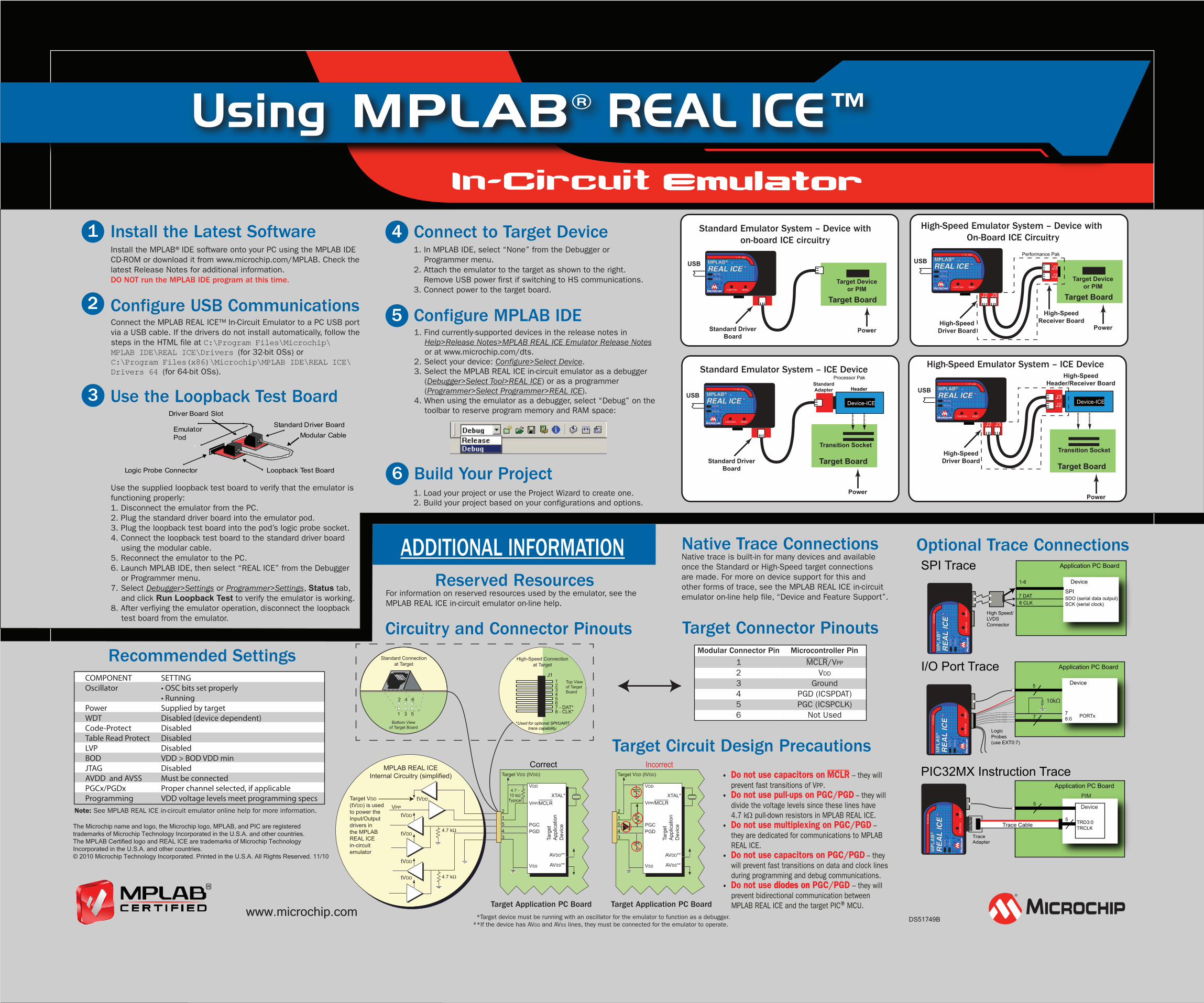
Emulator Using REAL ICE Install the Latest Software Install the MPLAB®IDE software onto your PC using the MPLAB IDE CD-ROM or download it from www.microchip.com/MPLAB. Check the latest Release Notes for additional information. DO NOT run the MPLAB IDE program at this time. Configure USB Communications Connect the MPLAB REAL ICE™ In-Circuit Emulator to a PC USB port via a USB cable. If the drivers do not install automatically, follow the steps in the HTML file at C:\Program Files\Microchip\ MPLAB IDE\REAL ICE\Drivers (for 32-bit OSs) or C:\Program Files(x86)\Microchip\MPLAB IDE\REAL ICE\ Drivers 64 (for 64-bit OSs). Connect to Target Device Use the supplied loopback test board to verify that the emulator is functioning properly: 1. Disconnect the emulator from the PC. 2. Plug the standard driver board into the emulator pod. 3. Plug the loopback test board into the pod’s logic probe socket. 4. Connect the loopback test board to the standard driver board using the modular cable. 5. Reconnect the emulator to the PC. 6. Launch MPLAB IDE, then select “REAL ICE” from the Debugger or Programmer menu. 7. Select Debugger>Settings or Programmer>Settings, Status tab, and click Run Loopback Test to verify the emulator is working. 8. After verfiying the emulator operation, disconnect the loopback test board from the emulator. Use the Loopback Test Board 1 2 3 Build Your Project 1. Load your project or use the Project Wizard to create one. 2. Build your project based on your configurations and options. 6 4 Reserved Resources For information on reserved resources used by the emulator, see the MPLAB REAL ICE in-circuit emulator on-line help. Recommended Settings COMPONENT SETTING Oscillator • OSC bits set properly • Running Power Supplied by target WDT Disabled (device dependent) Code-Protect Disabled T able Read Protect Disabled LVP Disabled BOD VDD > BOD VDD min JTAG Disabled A VDD and AVSS Must be connected PGCx/PGDx Proper channel selected, if applicable Programming VDD voltage levels meet programming specs Circuitry and Connector Pinouts ™ Emulator Pod Standard Driver Board Loopback Test Board Modular Cable Logic Probe Connector Driver Board Slot 1. In MPLAB IDE, select “None” from the Debugger or Programmer menu. 2. Attach the emulator to the target as shown to the right. Remove USB power first if switching to HS communications. 3. Connect power to the target board. Configure MPLAB IDE 1. Find currently-supported devices in the release notes in Help>Release Notes>MPLAB REAL ICE Emulator Release Notes or at www.microchip.com/dts. 2. Select your device: Configure>Select Device. 3. Select the MPLAB REAL ICE in-circuit emulator as a debugger (Debugger>Select Tool>REAL ICE) or as a programmer (Programmer>Select Programmer>REAL ICE). 4. When using the emulator as a debugger, select “Debug” on the toolbar to reserve program memory and RAM space: Optional Trace Connections Application PC Board Device SPI SDO (serial data output) SCK (serial clock) 1-6 7 DAT 8 CLK High Speed/ LVDS Connector SPI Trace ACTIVE STATUS REAL ICE ™ I n - C i r c u i t MPLAB ® FUNCTION RESET PIC32MX Instruction Trace Trace Adapter ACTIVE STATUS REAL ICE ™ I n - C i r c u i t MPLAB ® FUNCTION RESET 5 Logic Probes (use EXT0:7) I/O Port Trace ACTIVE STATUS REAL ICE ™ I n - C i r c u i t MPLAB ® FUNCTION RESET 7 Device PORTx Trace Cable Target Connector Pinouts Modular Connector Pin Microcontroller Pin 1 MCLR/VPP 2 VDD 3 Ground 4 PGD (ICSPDAT) 5 PGC (ICSPCLK) 6 Not Used 5 Standard Emulator System – Device with on-board ICE circuitry Target Board Target Device or PIM Power USB Standard Driver Board ACTIVE STATUS REAL ICE ™ I n -C i r c uit MPLAB ® FUNCTION RESET High-Speed Emulator System – Device with On-Board ICE Circuitry USB High-Speed Driver Board High-Speed Receiver Board ACTIVE STATUS REAL ICE ™ I n -C i r c uit MPLAB ® FUNCTION RESET Target Board Target Device or PIM Power J3 J2 J2 J3 Performance Pak High-Speed Emulator System – ICE Device High-Speed Header/Receiver Board Target Board Transition Socket Power USB High-Speed Driver Board ACTIVE STATUS REAL ICE ™ I n -C i r c uit MPLAB ® FUNCTION RESET J3 J2 J2 J3 Device-ICE Standard Emulator System – ICE Device USB Standard Driver Board Standard Adapter ACTIVE STATUS REAL ICE ™ I n -C i r c uit MPLAB ® FUNCTION RESET Target Board Transition Socket Power Device-ICE Header Processor Pak DS51749B www.microchip.com Native Trace Connections Native trace is built-in for many devices and available once the Standard or High-Speed target connections are made. For more on device support for this and other forms of trace, see the MPLAB REAL ICE in-circuit emulator on-line help file, “Device and Feature Support”. Application PC Board 10kΩ 7 6:0 Application PC Board 5 5 TRD3:0 TRCLK Device PIM ADDITIONAL INFORMATION 2 1 5 4 3 Target VDD (tVDD) 4.7 - 10 kΩ Typical Target Application PC Board VDD VPP/MCLR PGC PGD VSS AVDD** AVSS** XTAL* t e g r a T n o i t a c i l p p A e c i v e D tVDD 4.7 kΩ tVDD tVDD 4.7 kΩ tVDD tVDD MPLAB REAL ICE Internal Circuitry (simplified) Target VDD (tVDD) is used to power the Input/Output drivers in the MPLAB REAL ICE in-circuit emulator VPP Standard Connection at Target Bottom View of Target Board 2 4 6 1 3 5 Top View of Target Board *Used for optional SPI/UART trace capability. 1 2 3 4 5 6 7 - DAT* 8 - CLK* J1 High-Speed Connection at Target Correct *Target device must be running with an oscillator for the emulator to function as a debugger. **If the device has AVDD and AVSS lines, they must be connected for the emulator to operate. • Do not use capacitors on MCLR – they will prevent fast transitions of VPP. • Do not use pull-ups on PGC/PGD – they will divide the voltage levels since these lines have 4.7 kΩ pull-down resistors in MPLAB REAL ICE. • Do not use multiplexing on PGC/PGD – they are dedicated for communications to MPLAB REAL ICE. • Do not use capacitors on PGC/PGD – they will prevent fast transitions on data and clock lines during programming and debug communications. • Do not use diodes on PGC/PGD diodes on – they will prevent bidirectional communication between MPLAB REAL ICE and the target PIC®MCU. Target Circuit Design Precautions 2 1 5 4 3 Target VDD (tVDD) VDD VPP/MCLR PGC PGD VSS AVDD** AVSS** XTAL* t e g r a T n o i t a c i l p p A e c i v e D Incorrect Target Application PC Board Note: See MPLAB REAL ICE in-circuit emulator online help for more information. The Microchip name and logo, the Microchip logo, MPLAB, and PIC are registered trademarks of Microchip Technology Incorporated in the U.S.A. and other countries. The MPLAB Certified logo and REAL ICE are trademarks of Microchip Technology Incorporated in the U.S.A. and other countries. © 2010 Microchip Technology Incorporated. Printed in the U.S.A. All Rights Reserved. 11/10
Transcript of Emulator - Microchip Technologyww1.microchip.com/downloads/en/DeviceDoc/51749B.pdf · Emulator...
Emulator
Using REAL ICE
Install the Latest SoftwareInstall the MPLAB®IDE software onto your PC using the MPLAB IDE CD-ROM or download it from www.microchip.com/MPLAB. Check the latest Release Notes for additional information. DO NOT run the MPLAB IDE program at this time.
Configure USB CommunicationsConnect the MPLAB REAL ICE™ In-Circuit Emulator to a PC USB port via a USB cable. If the drivers do not install automatically, follow the steps in the HTML file at C:\Program Files\Microchip\MPLAB IDE\REAL ICE\Drivers (for 32-bit OSs) or C:\Program Files(x86)\Microchip\MPLAB IDE\REAL ICE\Drivers 64 (for 64-bit OSs).
Connect to Target Device
Use the supplied loopback test board to verify that the emulator is functioning properly: 1. Disconnect the emulator from the PC.2. Plug the standard driver board into the emulator pod.3. Plug the loopback test board into the pod’s logic probe socket.4. Connect the loopback test board to the standard driver board
using the modular cable.5. Reconnect the emulator to the PC.6. Launch MPLAB IDE, then select “REAL ICE” from the Debugger
or Programmer menu.7. Select Debugger>Settings or Programmer>Settings, Status tab,
and click Run Loopback Test to verify the emulator is working.8. After verfiying the emulator operation, disconnect the loopback
test board from the emulator.
Use the Loopback Test Board
1
2
3
Build Your Project1. Load your project or use the Project Wizard to create one.2. Build your project based on your configurations and options.
6
4
Reserved ResourcesFor information on reserved resources used by the emulator, see the MPLAB REAL ICE in-circuit emulator on-line help.
Recommended Settings COMPONENT SETTING Oscillator • OSC bits set properly • Running Power Supplied by target WDT Disabled (device dependent) Code-Protect Disabled Table Read Protect Disabled LVP Disabled BOD VDD > BOD VDD min JTAG Disabled AVDD and AVSS Must be connected PGCx/PGDx Proper channel selected, if applicable Programming VDD voltage levels meet programming specs
Circuitry and Connector Pinouts
™
EmulatorPod
Standard Driver Board
Loopback Test Board
Modular Cable
Logic Probe Connector
Driver Board Slot
1. In MPLAB IDE, select “None” from the Debugger or Programmer menu.
2. Attach the emulator to the target as shown to the right. Remove USB power first if switching to HS communications. 3. Connect power to the target board.
Configure MPLAB IDE1. Find currently-supported devices in the release notes in
Help>Release Notes>MPLAB REAL ICE Emulator Release Notes or at www.microchip.com/dts.
2. Select your device: Configure>Select Device.3. Select the MPLAB REAL ICE in-circuit emulator as a debugger
(Debugger>Select Tool>REAL ICE) or as a programmer (Programmer>Select Programmer>REAL ICE).
4. When using the emulator as a debugger, select “Debug” on the toolbar to reserve program memory and RAM space:
Optional Trace ConnectionsApplication PC Board
Device
SPI SDO (serial data output)SCK (serial clock)
1-6
7 DAT8 CLK
High Speed/LVDSConnector
SPI Trace
AC
TIV
E
STA
TU
S
RE
AL
ICE
™
In- C
ir cu i
t
MP
LA
B® F
UN
CT
ION
RE
SE
T
PIC32MX Instruction Trace
TraceAdapter
AC
TIV
E
STA
TU
S
RE
AL
ICE
™
In- C
ir cu i
t
MP
LA
B® F
UN
CT
ION
RE
SE
T
5
LogicProbes(use EXT0:7)
I/O Port Trace
AC
TIV
E
STA
TU
S
RE
AL
ICE
™
In- C
i r cu i
t
MP
LA
B® F
UN
CT
ION
RE
SE
T
7
Device
PORTx
Trace Cable
Target Connector PinoutsModular Connector Pin Microcontroller Pin
1 MCLR/VPP
2 VDD
3 Ground4 PGD (ICSPDAT)5 PGC (ICSPCLK)6 Not Used
5
Standard Emulator System – Device withon-board ICE circuitry
Target Board
Target Deviceor PIM
Power
USB
Standard DriverBoard
ACTIVE
STATUS
REAL ICE ™
I
n
-C
i
r
cuit
MPLAB®
FUNCTION RESET
High-Speed Emulator System – Device withOn-Board ICE Circuitry
USB
High-SpeedDriver Board
High-SpeedReceiver Board
ACTIVE
STATUS
REAL ICE ™
I
n
-C
i
r
cuit
MPLAB®
FUNCTION RESET
Target Board
Target Deviceor PIM
Power
J3J2
J2 J3
Performance Pak
High-Speed Emulator System – ICE DeviceHigh-Speed
Header/Receiver Board
Target Board
Transition Socket
Power
USB
High-SpeedDriver Board
ACTIVE
STATUS
REAL ICE ™
I
n
-C
i
r
cuit
MPLAB®
FUNCTION RESET
J3J2
J2 J3
Device-ICE
Standard Emulator System – ICE Device
USB
Standard DriverBoard
StandardAdapter
ACTIVE
STATUS
REAL ICE ™
I
n
-C
i
r
cuit
MPLAB®
FUNCTION RESET
Target Board
Transition Socket
Power
Device-ICE
Header
Processor Pak
DS51749Bwww.microchip.com
Native Trace ConnectionsNative trace is built-in for many devices and available once the Standard or High-Speed target connections are made. For more on device support for this and other forms of trace, see the MPLAB REAL ICE in-circuit emulator on-line help file, “Device and Feature Support”.
Application PC Board
10kΩ
76:0
Application PC Board
5
5 TRD3:0TRCLK
Device
PIM
ADDITIONAL INFORMATION
21543
Target VDD (tVDD)
4.7 -10 kΩTypical
Target Application PC Board
VDD
VPP/MCLR
PGCPGD
VSS
AVDD**
AVSS**
XTAL*
tegraTnoit acil pp
Aeci ve
D
tVDD
4.7 kΩ
tVDD
tVDD
4.7 kΩ
tVDD
tVDD
MPLAB REAL ICEInternal Circuitry (simplified)
Target VDD (tVDD) is used to power the Input/Output drivers in the MPLABREAL ICE in-circuit emulator
VPP
Standard Connectionat Target
Bottom Viewof Target Board
2 4 6
1 3 5
Top Viewof TargetBoard
*Used for optional SPI/UARTtrace capability.
1234567 - DAT*8 - CLK*
J1
High-Speed Connectionat Target
Correct
*Target device must be running with an oscillator for the emulator to function as a debugger.**If the device has AVDD and AVSS lines, they must be connected for the emulator to operate.
• Do not use capacitors on MCLR – they will prevent fast transitions of VPP.
• Do not use pull-ups on PGC/PGD – they will divide the voltage levels since these lines have 4.7 kΩ pull-down resistors in MPLAB REAL ICE.
• Do not use multiplexing on PGC/PGD – they are dedicated for communications to MPLAB REAL ICE.
• Do not use capacitors on PGC/PGD – they will prevent fast transitions on data and clock lines during programming and debug communications.
• Do not use diodes on PGC/PGD diodes on – they will prevent bidirectional communication between MPLAB REAL ICE and the target PIC® MCU.
Target Circuit Design Precautions
21543
Target VDD (tVDD)
VDD
VPP/MCLR
PGCPGD
VSS
AVDD**
AVSS**
XTAL*
tegraTnoit acil pp
Aeci ve
D
Incorrect
Target Application PC Board
Note: See MPLAB REAL ICE in-circuit emulator online help for more information.
The Microchip name and logo, the Microchip logo, MPLAB, and PIC are registered trademarks of Microchip Technology Incorporated in the U.S.A. and other countries. The MPLAB Certified logo and REAL ICE are trademarks of Microchip Technology Incorporated in the U.S.A. and other countries.© 2010 Microchip Technology Incorporated. Printed in the U.S.A. All Rights Reserved. 11/10