EMULATION OF WIND TURBINE USING DC MOTOR - …ethesis.nitrkl.ac.in/6322/1/110EE0236-12.pdf ·...
49
EMULATION OF WIND TURBINE USING DC MOTOR LIPSA PRIYADARSINI (110EE0219) & CHANDRANI DAS (110EE0236) Department of Electrical Engineering National Institute of Technology Rourkela
Transcript of EMULATION OF WIND TURBINE USING DC MOTOR - …ethesis.nitrkl.ac.in/6322/1/110EE0236-12.pdf ·...
EMULATION OF WIND TURBINE USING DC
MOTOR
LIPSA PRIYADARSINI (110EE0219)
&
CHANDRANI DAS (110EE0236)
Department of Electrical Engineering
National Institute of Technology Rourkela

EMULATION OF WIND TURBINE USING DC MOTOR
A Thesis submitted in partial fulfillment of the requirements for the degree of
Bachelor of Technology in “Electrical Engineering”
By
LipsaPriyadarsini (110EE0219)
&
Chandrani Das (110EE0236)
Under the guidance of
Dr Monalisa Pattnaik
Department of Electrical Engineering
National Institute of Technology, Rourkela
Rourkela-769008(ODISHA)
May, 2014

DEPARTMENT OF ELECTRICAL ENGINEERING
NATIONAL INSTITUTE OF TECHNOLOGY, ROURKELA
ODISHA,INDIA-769008
CERTIFICATE
This is to certify that the thesis entitled “Emulation of Wind Turbine using DC Motor”, submitted
by LipsaPriyadarsini (Roll. No. 110EE0219) & Chandrani Das (Roll. No. 110EE0236) in
partial fulfillment of the requirements for the award of Bachelor of Technology in Electrical
Engineering during session 2013-2014 at National Institute of Technology, Rourkela is a bonafide
record of research work carried out by them under my supervis ion and guidance.
The candidates have fulfilled all the prescribed requirements.
The Thesis which is based on candidates’ own work, have not submitted elsewhere for a
degree/diploma.
In my opinion, the thesis is of standard required for the award of Bachelor of Technology degree
in Electrical Engineering
Place: Rourkela
Dept. of Electrical Engineering Dr Monalisa Pattnaik
National institute of Technology Assistant Professor
Rourkela-769008

i
ACKNOWLEDGEMENT
We would like to articulate our sincere gratitude to our project supervisor, Dr MonalisaPattnaik
for her insightful suggestions on the project work and for guiding us during the project with her
encouragement, support and cooperation.
We would express our greatest appreciation to Prof A.K.Panda Head of the Department,
Electrical Engineering, and Prof P.K.Ray for their encouragement, comments and timely
suggestions throughout the course of this project work.
We would like to convey our sincerest gratitude and indebtedness to all our faculty members and
staffs of Department of electrical engineering, NIT Rourkela, who showed their great efforts and
guidance during required times without which it would have been very difficult to carry out our
project work. Moreover, an assemblage of this nature could never have been attempted without
our reference to the works of others. We acknowledge our indebtedness to all of them.
Finally, we would also like to extend our heart- felt thanks to our family for their moral support,
love and affection.
Lipsa Priyadarsini (110EE0219)
Chandrani Das (110EE0236)
B.Tech Electrical Engineering,
NIT Rourkela
ii
ABSTRACT
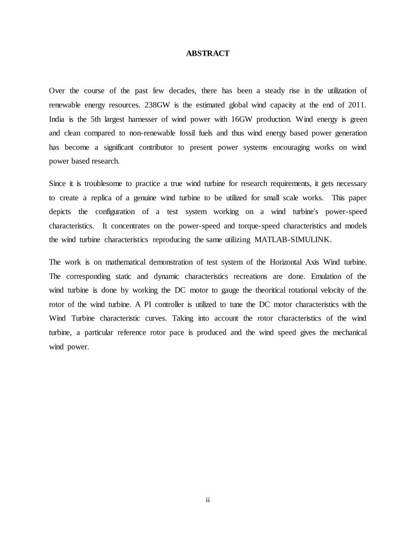
Over the course of the past few decades, there has been a steady rise in the utilization of
renewable energy resources. 238GW is the estimated global wind capacity at the end of 2011.
India is the 5th largest harnesser of wind power with 16GW production. Wind energy is green
and clean compared to non-renewable fossil fuels and thus wind energy based power generation
has become a significant contributor to present power systems encouraging works on wind
power based research.
Since it is troublesome to practice a true wind turbine for research requirements, it gets necessary
to create a replica of a genuine wind turbine to be utilized for small scale works. This paper
depicts the configuration of a test system working on a wind turbine's power-speed
characteristics. It concentrates on the power-speed and torque-speed characteristics and models
the wind turbine characteristics reproducing the same utilizing MATLAB-SIMULINK.
The work is on mathematical demonstration of test system of the Horizontal Axis Wind turbine.
The corresponding static and dynamic characteristics recreations are done. Emulation of the
wind turbine is done by working the DC motor to gauge the theoritical rotational velocity of the
rotor of the wind turbine. A PI controller is utilized to tune the DC motor characteristics with the
Wind Turbine characteristic curves. Taking into account the rotor characteristics of the wind
turbine, a particular reference rotor pace is produced and the wind speed gives the mechanical
wind power.

iii
CONTENTS
Acknowledgement i
Abstract ii
Contents iii
List of Figures v
Nomenclature vi
CHAPTER 1
INTRODUCTION
1.1. Motivation................................................................................................................................2
1.2. Background and Literature Review……………………………………………………….. 3
1.3. Thesis Objectives…………………………………………………………………………….3
1.4. Organization of Thesis............................................................................................................4
CHAPTER 2
WIND ENERGY
2.1. Wind turbines………………………………………………………………………………..7
2.2. Some Relevant Definitions………………………………………………………………….9
2.3. Wind turbine simulators…………………………………………………………………..10
2.4. Wind Energy conversion systems…………………………………………………………12

iv
2.5. Controlling Techniques of Wind Turbines .........................................................................13
2.6. Characteristics of Wind Turbines………………………………………………………14
CHAPTER 3
DC MOTOR
3.2. Electromechanical energy conversion device .....................................................................18
3.3. Separately excited DC motor……………………………………………………………...19
CHAPTER 4
MODELLING
4.1. Modelling of wind turbine…………………………………………………………………23
4.2. DC motor modelling……………………………………………………………………….28
4.3. Speed control of DC motor………………………………………………………………...29
4.4. The WECS system…………………………………………………………………………35
CHAPTER 5
CONCLUSION ………………………………………………………………………………...37
CHAPTER 6
SCOPE OF FUTURE WORK…………………………………………………………………39
References.....................................................................................................................................40

v
LIST OF FIGURES
FIG NO. TITLE PAGE NO.
2.1 Turbine output power versus turbine speed characteristics 15
2.2 Torque speed characteristics of wind turbine 16
3.1 Electric Motor 18
3.2 Electric Generator 18
4.1 Simulink model of wind turbine emulation 24
4.2 Subsystem of Simulink model 25
4.3 Subsystem of 𝐶𝑝 25
4.4 𝐶𝑝vs𝜆 curve characteristics 26
4.5 Power vs Wind speed 27
4.6 Simulink model of separately excited DC motor 28
4.7 Output Characteristics of DC Motor 29
4.8 Schematic representation for speed control of DC motor to 30
emulate wind turbine characteristics
4.9 Simulink model for speed control of DC Motor 31
4.10 Simulink model for DC Chopper subsystem 32
4.11 Output of speed control of DC motor 33
4.12 Curve for mechanical power vs motor angular speed 34
4.13 Wind Energy Conversion System 35

vi
NOMENCLATURE
r - Rotor speed
𝜆 - Tip Speed Ratio
Cp - Power coefficient
𝑟𝑟 - Rotor radius in meters
𝑉𝑤 - Wind speed in m/s.
𝑃𝑟 - Power extracted from turbine rotor
A - Area of the incident air stream
U - Velocity of air flow
𝜌 - Density of air flow
- Flux linkage

1
CHAPTER 1
Introduction

2
1.1. MOTIVATION
Pollution and global warming have become a burning topic of priority as greenhouse gas
emissions increase in the atmosphere thanks to persistent dependence on fossil fuels. The long
term consequences of pollution include increase in temperature and rise in sea levels. The
melting of polar ice-caps, decrease in ozone layer, increase in level of poisonous gases in the
atmosphere owe a lot of credit to the conventional, non-renewable energy generation techniques.
Climate scientists continue to warn about the potential catastrophic effects of unchecked use of
fossil fuels. The growth of carbon dioxide (the main cause of climate change) in the atmosphere,
has accelerated inexorably, as countries continue using fossil fuels to power their economies.
Thus the dire need of the hour is to have a mass shift of energy generation techniques to the
renewable and pollution free form of energy. Added to the advantage of being eco-friendly, these
forms of energy being unlimited at the source would never run out unlike conventional fossil
fuels.
The past few years have experienced a fast rise in the electricity generation from wind energy
resources. kWh per annum is the estimated maximum extractable energy from the 0-100
meters layer of atmosphere.
Advantages of using wind energy:
1. Being powered by wind, this is a clean fuel. It does not have harmful impact on environment
unlike fossil fuels which extract energy from combustion of coal and natural gas. It is an eco-
friendly source of energy without any form of greenhouse gas emissions.
2. Wind is available in abundance and thus is sustainable. This makes it reliable to be accessed and
depend upon.
3.Winds are caused due to non-uniform heating of atmosphere by sun, earth’s rotation and surface
irregularities on earth. Thus it relies on renewable form of solar energy.
1210

3
4. Apart from the initial establishing expenses, wind turbines are otherwise low-priced form of
energy and can be built even on farms etc supporting rural locations at wind sites.
1.2. LITERATURE REVIEW:
Fixed pitch wind turbines are used in power generation systems for generating power varying from
small to middle power. Presently, high and medium power systems use the variable-pitch wind
turbines, while fixed pitch turbines finds its usage limited to various low-power applications. In large
wind turbines, the power extracted is controlled by means of the blade pitch angle and the turbine
speed. When the power range of the turbines is smaller, the power is controlled by either turbines
that control the speed and not the pitch angle or turbines that change the pitch angle and not speed
[2].
The mechanical power characteristics of a fixed-pitch turbine is expressed as a function of wind
speed [3]. The maximum value of the power curve is obtained for each wind speed. A wind turbine
emulator reproduces those power curves. Power electronic converter converts the turbine speed.
For the purpose of laboratory tests, a type of system is designed that emulates the operation and
characteristics of a wind turbine. DC motors, permanent magnet motors or SCIMs are usually used
[4-11]. The motor is controlled to have power curves similar to the wind turbine characteristics.
Microprocessor-based control are used that takes turbine speed and wind speed as input parameters
and thus the reference torque of the motor is calculated.
1.3.THESIS OBJECTIVES:
The following objectives are attained at the end of this project work:
1) Study of wind turbines, their types and method of their working.
2) Modeling of wind turbine and its analysis.
4
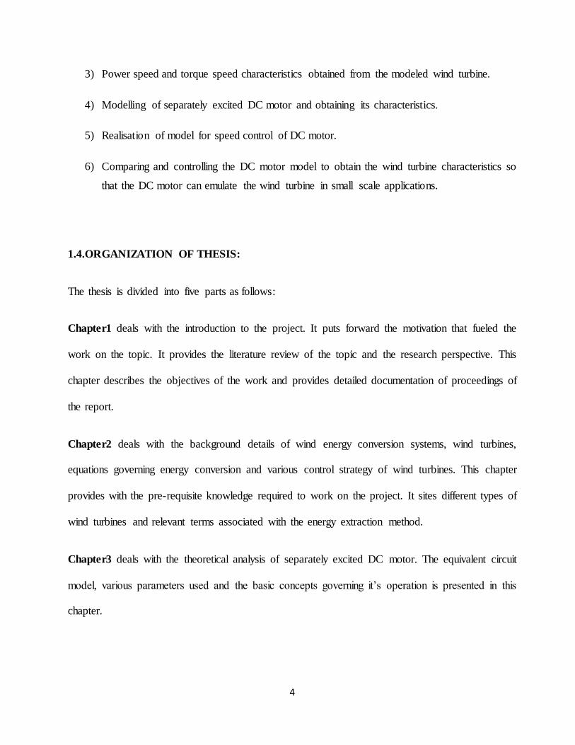
3) Power speed and torque speed characteristics obtained from the modeled wind turbine.
4) Modelling of separately excited DC motor and obtaining its characteristics.
5) Realisation of model for speed control of DC motor.
6) Comparing and controlling the DC motor model to obtain the wind turbine characteristics so
that the DC motor can emulate the wind turbine in small scale applications.
1.4.ORGANIZATION OF THESIS:
The thesis is divided into five parts as follows:
Chapter1 deals with the introduction to the project. It puts forward the motivation that fueled the
work on the topic. It provides the literature review of the topic and the research perspective. This
chapter describes the objectives of the work and provides detailed documentation of proceedings of
the report.
Chapter2 deals with the background details of wind energy conversion systems, wind turbines,
equations governing energy conversion and various control strategy of wind turbines. This chapter
provides with the pre-requisite knowledge required to work on the project. It sites different types of
wind turbines and relevant terms associated with the energy extraction method.
Chapter3 deals with the theoretical analysis of separately excited DC motor. The equivalent circuit
model, various parameters used and the basic concepts governing it’s operation is presented in this
chapter.

5
Chapter4 presents Matlab simulation of various characteristics. IT deals with wind turbine
modelling and DC motor modelling. Simulation of dumping wind turbine data on DC motor model.
The Cp –TSRcharacteristics of the wind turbine is obtained and compared with the DC motor
characteristics which is controlled till the desired outcome is reached.
Chapter 5 provides the conclusion of the work done
Chapter6 is about the future scopes and further improvements of the project.

6
CHAPTER 2
Wind Energy

7
2.1. WIND TURBINES
Over the course of the past few decades, there has been a steady rise in the utilization of renewable
energy resources. 238GW is the estimated global wind capacity at the end of 2011. India is the 5th
largest harnesser of wind power with 16GW production. Wind energy is green and clean compared
to non-renewable fossil fuels and thus wind energy based power generation has become a significant
contributor to present power systems encouraging works on wind power based research.
Since it is troublesome to practice a true wind turbine for research requirements, it gets necessary to
create a relica of a genuine wind turbine to be utilized for small scale works. This paper depicts the
configuration of a test system working on a wind turbine's power-speed characteristics. It
concentrates on the power-speed and torque-speed characteristics and models the wind turbine
characteristics reproducing the same utilizing MATLAB-SIMULINK.
In the wind energy conversion system, first the wind energy is captured by wind turbine. Using
generator,it is converted into electrical power. So it is very important to study the characteristics of
wind turbine. As the wind turbines are big in size and quite expensive, it is not at all possible to do
the research work in the practical wind farm. For the research to be carried out on wind power
technology, the need is to develop a simulator to simulate wind turbines which do not depend on
natural wind turbine simulator and that reduces experimental cost to a large extent . It is very
meaningful to develop in a laboratory a wind turbine simulator that can simulate the real wind turbine
in both steady state as well as in dynamic state .
There are different designs of wind turbines and they are broadly classified in two categories which
is based on orientation of the axis of rotation. They are -
1. Horizontal Axis Wind Turbines, or HAWTS.
2. Vertical Axis Wind Turbines, or VAWTS.
\

8
Horizontal axis wind turbines
In Horizontal-axis wind turbines (HAWT), the rotor shaft and electrical generator are placed at the
top of the tower facing the wind. The function of the gearbox is to turn the slow rotation of the
blades into a speed that drives the electrical generator in a perfect way. Modern HAWTs consists of
rotorsthat is similar to propellers of aircrafts, which basically operate on aerodynamic principles. In
that, the air passes over the airfoil fashioned blades which develop a lifting force that helps in turning
a rotor.
Vertical axis wind turbines
The rotor shaft is vertically arranged. An important advantage of this arrangement is that the turbine
need not point into the wind to be effective, when the wind direction is highly variable wind site. In
VAWT arrangement, the gearbox and generator can be placed close to the ground, using a ground
based gear box, which improves the access for maintenance. Further advantage of a VAWT over the
counterpart HAWT is that Yaw mechanism is not needed because wind can be harnessed from any
direction. The main disadvantages are low rotational speed with the higher cost of drive train
because of higher torque, and the lower power coefficient.
As a turbine is positioned on a rooftop, the wind is redirected by the building over the roof which
doubles the speed of the wind coming to the turbine. The efficiency is maximum if the height of the
turbine tower mounted in the rooftop is around 50% of the height of the building.

9
2.2. SOME RELEVANT DEFINITIONS
Described below the explanations of some significant parameters associated with wind turbines.
Control of the wind turbine models is facilitated by these parameters.
2.2.1. Solidity
The ratio of the blade area projection to the intercepted wind area is defined as solidity.
The projected blade area here is denoted by the blade area seen by the wind or projected in the
direction of the wind. The area intercepted by the wind is also defined as the swept area.
Solidity =projected blade area
rotor swept area
Study shows direct association of solidity with torque and speed. High-solidity rotors are
characterized with greater torque and lower speed appropriate for jobs like pumping water. On the
other hand, low-solidity rotors are characterized with greater speed and lesser torque. This is usually
appropriate for electrical power generation.
Hence, only high speed propeller category and Darrieus category of wind turbines are well-matched
for electric power generation.
2.2.2. Tip Speed Ratio (TSR)
𝜆 or the Tip Speed Ratio (TSR) is the ratio of velocity of the rotor’s blade tip to the air flow.
𝝀 =𝝎𝒓𝒓𝒓
𝑽𝒘
where, 𝑟𝑟= rotor radius in meters, 𝜔𝑟= angular speed in rad/sec and 𝑉𝑤= wind speed in m/s.
2.2.3. Coefficient of Performance
The power essentially taken from the wind turbine rotor, 𝑃𝑟 , is some portion of the offered power,
described by the coefficient of performance, 𝐶𝑝 , that is basically a type of power conversion
efficiency:

10
𝑪𝒑 =𝑷𝒓
𝑷 (6)
Here 𝐶𝑝 (power coefficient) signifies the efficiency of the blades to obtain the power in wind. It is
the portion of power which is fetched from the wind to the turbine blades. The theoretical boundary
of 𝐶𝑝 is about 59.3%.
2.3. WIND TURBINE SIMULATORS
Due to the fast upsurge of wind power establishments, study close to wind energy structures is
developed. Because of that equipment which can simulate effectively the purpose and operation of
a wind turbine setup in a laboratory is of great importance. The primary purpose of this type of
equipment, that possibly be termed as a wind turbine simulation device, is the capability to determine
dynamic and static characteristics of an actual wind turbine.
There exists various categories of wind turbine simulators evolved using various types of motors
and control practices. DC motors, induction motors and quite seldom, synchronous motors are
utilized as the mechanical prime mover of the wind turbine simulators. Wind turbine simulating
device employing separately exited DC motors generally utilize armature and field voltage control
techniques to realize static characteristics of a fixed pitch wind turbine. These simulators are basic,
unsophisticated and usually neglect the dynamic operations.
Few simulators employ permanent magnet synchronous motors as the mechanical prime mover with
a voltage source converter. Like the prime movers, several categories of generators are employed at
various wind turbine simulators. Induction generators are most widely used with the irregular use of
DC and synchronous generators.
Wind, which is the normal motion of air in the atmosphere, is produced by pressure variations on
the surface of the earth owing to the irregular warming via solar irradiation. From fluid mechanics,
the air current can be examined as mass flow with kinetic energy [1] given by:
𝑑𝑚
𝑑𝑡= 𝜌𝐴𝑈 (1)

11
𝐸𝑘 = 0.5𝑚𝑣2 (2)
𝑃𝑘 = 0.5𝜌𝐴𝑈3 (3)
here “A” is the area of the incident air stream, U and v the velocity and density of the flow
respectively. Generally, “A”, the stream area of interest is denoted as the area swept by the rotor of
a wind energy conversion system (WECS). These systems transform the linear momentum of the air
stream into a rotation of the WECS rotor, with a maximum possible efficiency of 59.26%, referred
to as Betz limit. Additionally, it can be witnessed from (1) that the obtainable power in the wind
surges at the cube of the air velocity, and from a substitution of “A” for the area of disk:
𝑃𝑘 = 0.5𝜌𝜋𝑅2𝑈3 (4)
Thus, a two fold escalation in the radius of a WECS’ blade geometry consequences in a four-fold
surge in captured energy.
2.4. WIND ENERGY CONVERSION SYSTEM
Till date, there have been a range of WECS’ designs; but up till now the most common and
extensively accepted is the horizontal axis wind turbine (HAWT). As made clear in the Introduction,
the design of interest is the inexpensive, low-power HAWT design is widely used in rural and urban
areas. Such systems are becoming increasingly popular due to increased concern over greenhouse
gas emissions, and consist of following four main components [2]:
2.4.1. Rotor assembly:
Blades of the turbine along with the hub upon which the blades are mounted comprises the rotor
assembly. The response of a wind turbine is critically affected by blade geometry, and in numerous
designs, this factor is also the most costly part of the turbine unit.

12
2.4.2. Drive train:
Linking the rotor to the generator is the drive train. In larger wind turbine systems, the drive train
comprises of gearing to escalate the velocity of rotation from the rotor into the generator. Small
turbines lack this attribute; the drive train for those systems is merely a linking shaft.
2.4.3. Generator:
The generator transforms the mechanical rotation of the drive train into electricity. Small turbine
generators are normally of the 3-phase, permanent magnet type; yet various generator classes are
also employed.
2.4.4. Controller:
For shielding the system, apart from transforming the output of the generator to domestic voltages,
the necessity of power electronic interface arises. As already mentioned, the working of a turbine is
seriously affected by its geometry. Characterization of the performance is usually done with a Cp -
curve; a plot of power coefficient to the tip speed ratio of the blades. The power coefficient Cp
signifies the efficiency of the blades in taking out the power stored in the wind, whereas the tip speed
ratio (TSR) is defined as the ratio of the blade speed to the air stream.
2.5. CONTROLLING TECHNIQUES OF WIND TURBINES
It is desirable that the power captured from the wind turbine should be maximized. Moreover, it is
essential that under any circumstances, the safety of the wind turbine should not be compromised.
Thus, proper regulation of power plays a very important role in the operation of wind turbine. In
order to prevent any damage to the wind turbine in case of very high wind speed, it is important to
limit the amount of power absorbed which can be done by regulating the aerodynamic forces acting
upon the rotor. The commonly employed techniques to achieve the above objective are as follows
2.5.1. Pitch control
Pitch control helps the blades to be twisted into or out the wind. It results into deviation of the force
exerted by the wind on the shaft of the rotor. This control has many advantages over other controls:
power control is perfect,
Aided startup, and
Alternative stop.
13
Power output can be limited to the rated power of the generator using pitch control at higher wind
speeds. The system complexity is one of the disadvantages in the pitch mechanism and one more
disadvantage is greater power fluctuations at high wind speeds.
2.5.2. Stall control
a. Passive Stall control
The informal controlling method for a wind turbine is stall control and stalling will take place when
the wind speeds crosses a certain limit . Thus, the lift force exerted on the rotor stops starting the
turbine to stall and restrict them in a allowable speed limit. Therefore, the turbine is safe and secured
at a very higher wind speeds. Power control is very smooth using this process. The disadvantage is
that , at low wind speeds turbines operate at a lesser efficiency than the measured value . Moreover
the reasons behind the disparities in steady state power extraction are due to the variation of grid
frequencies and air density.
b. Active Stall Control
The active stall control was a replacement over passive stall control. Instead of using natural
stalling, pitching was used by this system for controlling the stall of the blade actively. Therefore
, maximum efficiency is achieved by pitching the blades in the same manner as that of pitch
controlled wind turbine at low wind speeds and at higher wind speeds, to allow them into a deeper
stall, the blades are oriented to some extent into the direction opposed to that of a pitch controlled
turbine.
Various advantages of the above system are Power fluctuations will be less in case of obtaining
smoother limited power. It can compensate differences in air density. It is quite easier for the system
to obtain emergency stops and again starting up the wind turbine.
2.6. CHARACTERISTICS OF WIND TURBINE:
Different characteristics of a wind turbine are studied and plotted.
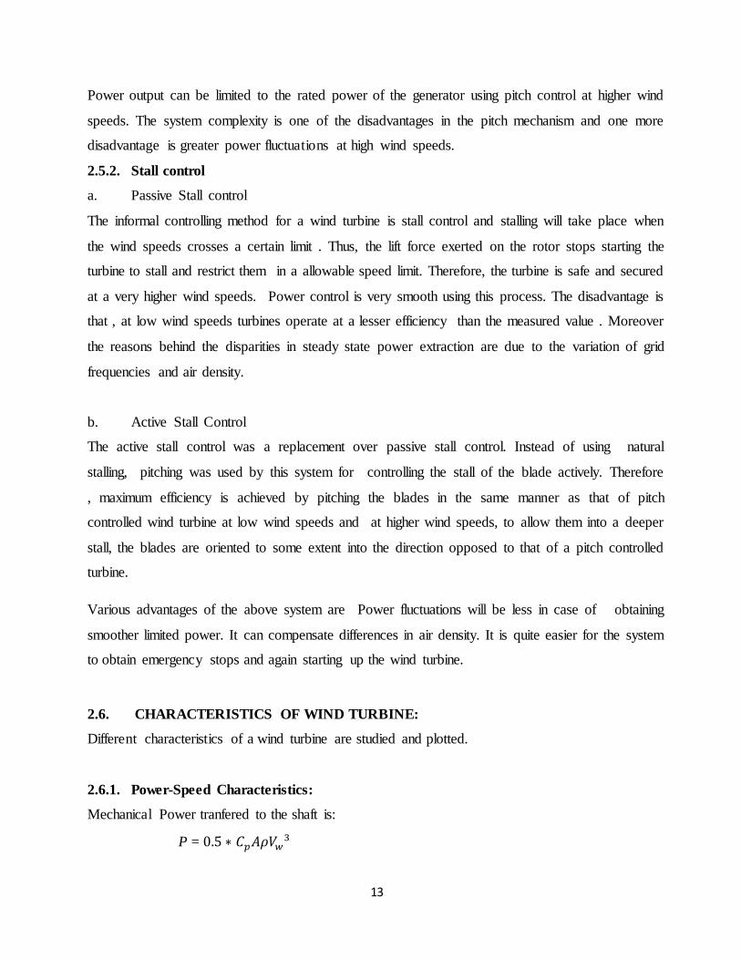
2.6.1. Power-Speed Characteristics:
Mechanical Power tranfered to the shaft is:
P = 0.5 ∗ 𝐶𝑝𝐴𝜌𝑉𝑤3
14
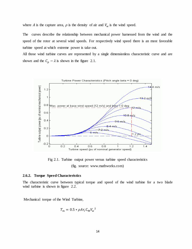
where 𝐴 is the capture area, 𝜌 is the density of air and 𝑉𝑤 is the wind speed.
The curves describe the relationship between mechanical power harnessed from the wind and the
speed of the rotor at several wind speeds. For respectively wind speed there is an most favorable
turbine speed at which extreme power is take out.
All those wind turbine curves are represented by a single dimensionless characteristic curve and are
shown and the 𝐶𝑝 − 𝜆 is shown in the figure 2.1.
Fig 2.1. Turbine output power versus turbine speed characteristics
(fig. source: www.mathworks.com)
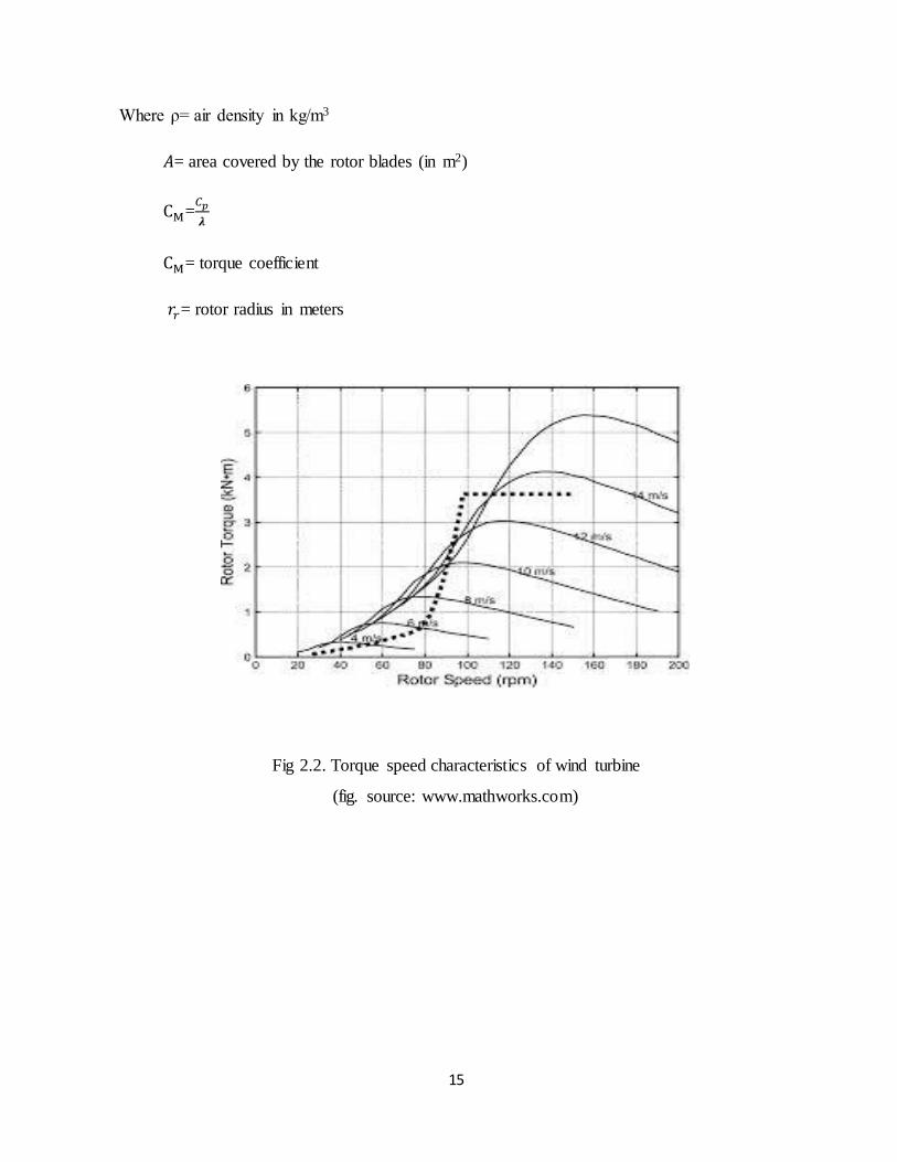
2.6.2. Torque Speed Characteristics
The characteristic curve between typical torque and speed of the wind turbine for a two blade wind turbine is shown in figure 2.2.
Mechanical torque of the Wind Turbine,
𝑇𝑚 = 0.5 ∗ 𝜌𝐴𝑟𝑟CM𝑉𝑤2
15
Where ρ= air density in kg/m3
𝐴= area covered by the rotor blades (in m2)
CM=𝐶𝑝
𝝀
CM= torque coefficient
𝑟𝑟= rotor radius in meters
Fig 2.2. Torque speed characteristics of wind turbine
(fig. source: www.mathworks.com)

16
CHAPTER 3
DC Motor

17
DC motors make up most of the mechanical movement we see around us. They convert electrical
energy in DC form to mechanical energy. Due to its simple operation and control and due to its
availability at wide range of ratings it has been chosen for simulating wind in the wind turbine
system.
3.1. ELECTROMECHANICAL ENERGY CONVERER DEVICE
It is basically a medium of transport between the input and output sides. Various types of electrical
machines namely DC machine, induction machine and synchronous machine are employed widely
for conversion of electromechanical energy. Conversion of electromechanical energy occurs
whenever there is a variation in magnetising flux associating a coil, due to mechanical motion.
Electric Motor
The input to the system is electrical energy obtained from the supply while the output is in the form
of mechanical energy given to the load. The system is described in Fig 3.1.
Electrical energy Mechanical
Energy
Source Motor load
Fig. 3.1. Electrical motor
Electrical Generator
The system is described in fig 3.2.
Mechanical energy Electrical
energy
Source Generator load
Fig.3.2. Electrical generator
Electromechanical energy
converter device
Electromechanical energy
conversion device
18
3.2 SEPARATELY EXCITED DC MOTOR
Different supply voltage is provided to field and armature winding in a separately excited dc motor.
Field flux to armature is facilitated by field winding. On application of dc voltage to motor, current
is supplied to the armature winding via brushes and commutator. Since current carrying rotor is
positioned in magnetic field, so it generates a back emf and a torque to equalize load torque at certain
speed.
3.2.1Analysis of DC separately excited motor
When field current 𝐼𝑓 is supplied to a separately excited dc motor and an armature current 𝐼𝑎
circulates in the circuit, the motor generates a back EMF and a torque to equalize the load torque at
a certain speed. The field current 𝐼𝑓 does not depend on armature current𝐼𝑎 . Separate excitation is
provided to each winding. Armature current variation does not result in variation in the field current.
Normally 𝐼𝑓 is quite lesser compared to 𝐼𝑎 .
The total emf induced in the motor is given by the equation
𝐸 = 𝑘𝑒𝜙𝜔𝑚
𝐿𝑓 and R denote the inductance and resistance of the field winding respectively. The magnetic field
required for motor working is generated by the current 𝐼𝑓 . In the armature (rotor) equivalent circuit,
V is termed as the voltage put on athwart the motor terminals , 𝐼𝑎 is the current circulating in the
armature circuit, 𝑅𝑎 refers to the resistance value of the armature winding, and E refers to the total
voltage that is induced in the armature.
𝑉 = 𝐸 + 𝐼𝑎𝑅𝑎
For invariant field current in case of a separately excited DC motor, the flux can be expected to be
constant.

19
From equations, it was found out that
So,
Now, using the above equation it can be clearly deduced that speed of DC motor is governed by
applied voltage, armature current, armature resistance and field flux.
Thus, there are three methods of regulating speed of a DC motor.
1. Flux control method
2. Armature control method
3. Voltage Control method
1. Flux Control method
The speed can be improved by lessening the flux as well as vice versa holds true. The flux of a dc
motor can be altered by varying 𝐼𝑓 by fluctuating the input voltage.
If we fluctuate If, flux 𝜙 will change, hence speed will change. For varying If an external resistance
is linked in series with the field windings. When no external resistance is connected and rated voltage
is applied across field coil, the field coil generates rated flux. The purpose of adding an external
resistance is to limit the flux level by varying the former. Thus for controlling the speed above the
base speed decrement of field current will result in increment in motor speed.
2. Armature Control Method
When there is requirement of speeds lower than the no-load speed the armature control technique is
employed. Since the supply voltage is usually invariant, the voltage athwart the armature is varied

20
by introducing a variable rheostat in series with the armature circuit. An increase in the controller
resistance causes the voltage to decrease athwart the armature and hence decrementing the armature.
For a constant load torque, speed is roughly proportional to the voltage athwart the armature. From
the characteristic plot for speed vs armature current it is observed that the fall in the speed varies
inversely with the value of resistance in the armature circuit.
3. Voltage Control Method
(a) Multiple Voltage Control:
According to this method, a fixed exciting voltage is impressed upon the shunt field of the motor.
And using appropriate switch gear the armature is provided with various voltages by joining it
athwart one of the different voltages. These different voltages will govern the armature speed
because of the direct proportionality. The shunt field regulator is employed to achieve the
intermediate speeds. Separately excited dc motors are best suited for this method. In this method of
speed control, constant parameters are 𝑅𝑎 and 𝜙.
In normal operation, the drop along the armature resistance is quite small compared to E and
therefore:
E = V
Since, 𝐸 = 𝑘𝑒𝜙𝜔𝑚
Angular speed can be expressed as
𝜔𝑚 =𝑉
𝐾 ,𝑎𝑠 𝑘𝑒𝜙 = 𝐾
From this equation,
The speed varies linearly with V provided flux is kept constant.
The speed surges as the terminal voltage is risen and vice versa also holds true.

21
CHAPTER 4
Modelling
22
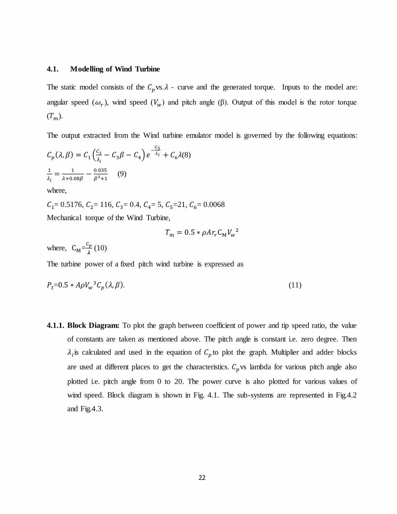
4.1. Modelling of Wind Turbine
The static model consists of the 𝐶𝑝vs.𝜆 - curve and the generated torque. Inputs to the model are:
angular speed (𝜔𝑟 ), wind speed (𝑉𝑤) and pitch angle (β). Output of this model is the rotor torque
(𝑇𝑚).
The output extracted from the Wind turbine emulator model is governed by the following equations:
𝐶𝑝(𝜆, 𝛽) = 𝐶1 (𝐶2
𝜆𝑖− 𝐶3𝛽 − 𝐶4) 𝑒
−𝐶5𝜆𝑖 + 𝐶6𝜆(8)
1
𝜆𝑖=
1
𝜆+0.08𝛽−
0.035
𝛽3+1 (9)
where,
𝐶1= 0.5176, 𝐶2= 116, 𝐶3= 0.4, 𝐶4= 5, 𝐶5=21, 𝐶6= 0.0068
Mechanical torque of the Wind Turbine,
𝑇𝑚 = 0.5 ∗ 𝜌𝐴𝑟𝑟CM𝑉𝑤2
where, CM=𝐶𝑝
𝝀 (10)
The turbine power of a fixed pitch wind turbine is expressed as
𝑃𝑡=0.5 ∗ 𝐴𝜌𝑉𝑤3𝐶𝑝(𝜆, 𝛽). (11)
4.1.1. Block Diagram: To plot the graph between coefficient of power and tip speed ratio, the value
of constants are taken as mentioned above. The pitch angle is constant i.e. zero degree. Then
𝜆𝑖is calculated and used in the equation of 𝐶𝑝 to plot the graph. Multiplier and adder blocks
are used at different places to get the characteristics. 𝐶𝑝vs lambda for various pitch angle also
plotted i.e. pitch angle from 0 to 20. The power curve is also plotted for various values of
wind speed. Block diagram is shown in Fig. 4.1. The sub-systems are represented in Fig.4.2
and Fig.4.3.
23
Fig 4.1. Simulink model of wind turbine emulation
24
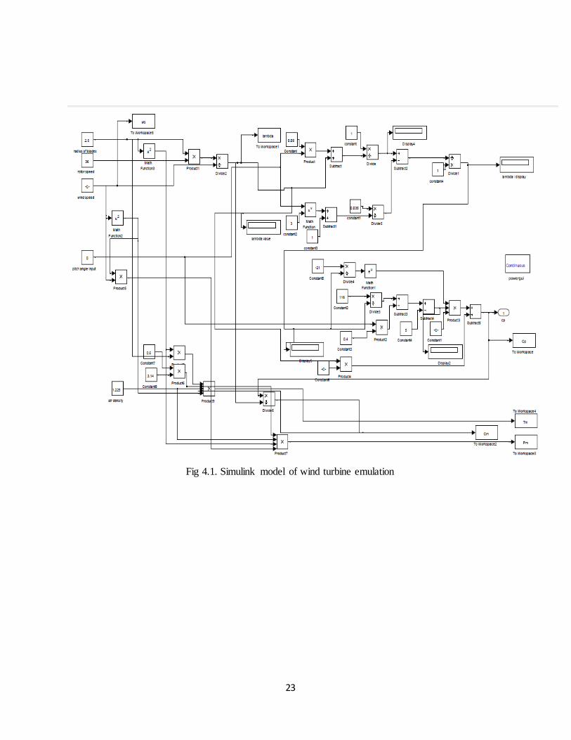
Fig 4.2. Subsystem of 1
𝜆𝑖=
1
𝜆+0.08𝛽−
0.035
𝛽3+1
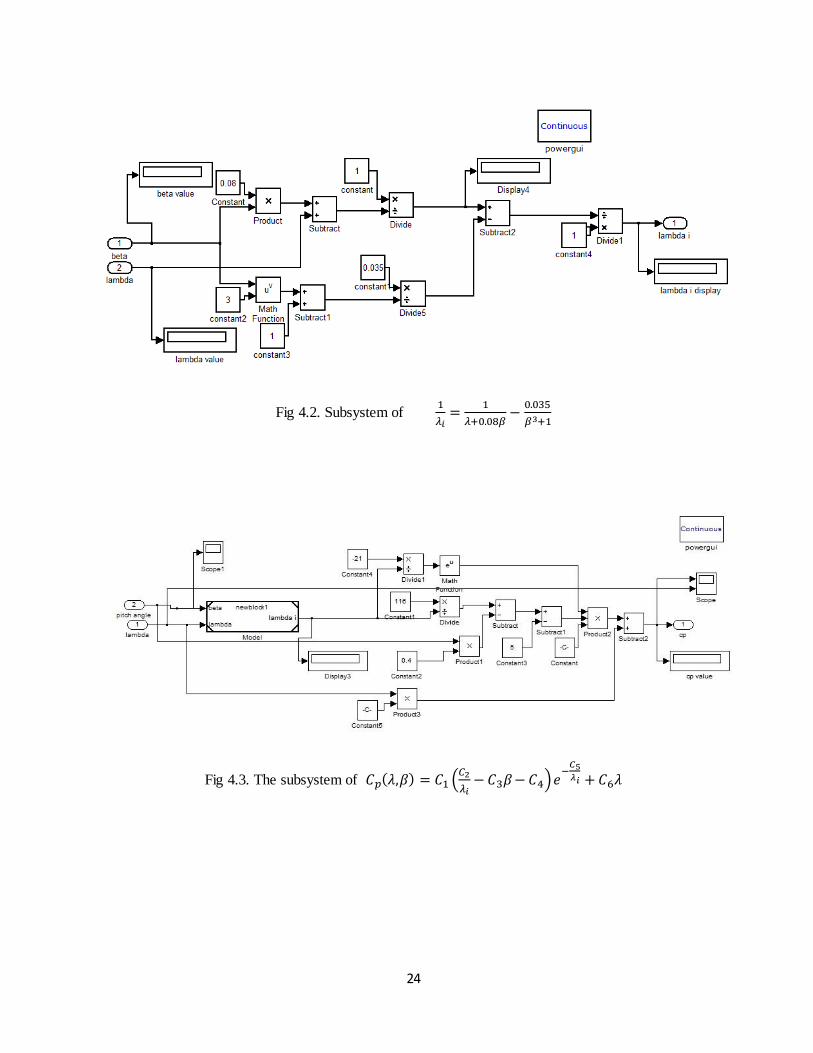
Fig 4.3. The subsystem of 𝐶𝑝(𝜆,𝛽) = 𝐶1 (𝐶2
𝜆𝑖− 𝐶3𝛽 − 𝐶4)𝑒
−𝐶5𝜆𝑖 + 𝐶6𝜆

25
4.1.2. Characteristics (𝐶𝑝 vs. 𝜆 Curve): Both TSR and 𝐶𝑝 are calculated and taken to workspace
and the graph plotted between 𝐶𝑝 and𝜆. Output is as shown in Fig.4.4.
Fig 4.4. 𝐶𝑝vs𝜆 curve characteristics
The graph shows the variation of Tip Speed Ratio with power coefficient at different beta
values.

26
4.1.3. Power Speed Characteristics Of Wind Turbine:
The output obtained is shown in Fig. 4.5. The graph between power generated from the wind
turbine and the wind speed shows that increases proportionate to the cube of the wind speed.
Fig 4.5. Power vs Wind speed

27
4.2. DC Motor Modelling
The DC motor is modeled using the equations and the blocks of the simulink. The gain blocks with
different values were chosen and the above circuit is made. Two integrators are used as they are
required to implement the equation.
4.2.1. Block Diagram:
In the block diagram in Fig. 4.6., different gain parameters are used. Values of different gain blocks
are: Gain : 1/0.5, Gain1: 1/0.01, Gain2: 0.01, Gain3 :0.01, Gain5:0.01
Fig 4.6. Simulink model of separately excited DC motor

28
4.2.2. Output Characteristics: Output is speed and it is taken to a workspace. Output characteristic
has been plotted between speed and time for different inputs. The graph is shown in Fig.4.7.
where speed variation is plotted.
Fig 4.7. Output Characteristics of DC Motor
4.3. Speed Control of DC Motor
The wind turbine model takes the wind speed, pitch angle and angular speed as inputs. Gear
ratio conversion is applied to the angular speed. The torque constant is multiplied with the
calculated reference torque in the model and the reference current is calculated. This
reference current is equated with the armature current of the DC motor. The current error is
lessened by a tuning a proportional-integral controller. The block diagram of this system is
shown in Fig. 4.8.

29
Fig.4.8. Schematic representation for speed control of DC motor to emulate wind turbine
characteristics
Under steady state, the emulator power and current matches with the reference power and
current, respectively. However, the shaft speed varies in accordance with the wind speed
variation. The investigations of the emulator action under various wind profile ensures the
effectiveness of the WTE.

30
4.3.1. Block Diagram:
Speed control of dc motor using PI controller is presented in Fig. 4.9.
Fig.4.9. Simulink model for speed control of DC Motor

31
The DC Chopper Model: The subsystem shown in Fig.4.10 represents the chopper model
Fig.4.10. Simulink model for DC Chopper subsystem

32
4.3.2. Output:
The output curves are shown in Fig 4.11 :
Fig 4.11.Output of speed control of DC motor

33
These curves in Fig.4.12 obtained for dofferent votage values, resembles with the Cp vs Tip-speed-
ratio characterisitcs of the modelled wind turbine for different pitch angles.
Fig 4.12. Curve for mechanical power vs motor angular speed

34
4.4. The WECS System
The wind speed, pitch angle and angular speed are taken as inputs to the wind turbine model.
The angular speed is encounters conversion through gear ratio. The calculated reference
torque is used to estimate the reference current. This is compared with the armature current
of DC motor. The current error is tuned by a proportional-integral controller. At steady state
conditions, the emulator current and emulator power is same as the reference current and
power. The wind speed variation determines the shaft power variation. The effectiveness of
the Wind Turbine Emulator is determined by emulator action at various wind profile. The
motor is coupled to the induction generator. The power generated is supplied to the grid.
Fig. 4.13. Wind Energy Conversion System
35
CHAPTER 5
Conclusion

36
The concept of wind turbine was studied in detail and the modelling in MATLAB/SIMULINK was
done. The project develops a wind turbine emulator that provides characteristics of wind turbine
based on wind speed and other gradient factors. It verifies the modeling of wind turbine as a speed
source that can be further used for development of more efficient energy converters for extraction
of power from wind turbine. Such emulators are vital for development of WECS to encounter all
sorts of unpredictability in wind and environment in order to ensure the continuity of wind energy
hence contributing to more encouragement of Wind Energy. The project implements speed control
of DC motor using PI controller. DC choppers are used. The characteristics of wind turbine with DC
motor are obtained by using PI controller. This operational wind turbine emulator could be used for
research on a small wind energy conversion system and thus form a test-bed to experiment and
develop other control strategies.

37
Chapter 6
Scope of Future Work

38
The emulated wind turbine model developed in the present work can be redesigned to
operate in transient conditions and the required characteristic plots can be obtained for a
more realistic approach.
The control method of the DC motor can be improvised to have a more efficient model
that can emulate well the real characteristic operation of a wind turbine.
The wind model can be dumped on the DC motor using microcontroller programming or
FPGA program etc. to have the hardware implementation of the emulation model.
The emulated turbine may be coupled with an induction generator to build a stand-alone
system that can be used for various small scale applications.
39
REFERENCES
[1] Olimpo Anaya-Lara, N.Jenkins, J.Ekanayake, P.Cartwright, M.Hughes, “Wind energy
generation modeling and control”, Vol. I. New york: Wiley, 2009
[2] Pena R. S., Clare J. C., Asher G. M., “Implementation of vector control strategies for a
variable speed double fed induction machine for wind generation system”, Proc. EPE,
Sevilla, 1995, pp. 3075-3080
[3] Kazmierkowski M. P., Krishnan R., Blaabjerg F., “Control in Power Electronics Selected
Problems”, Academic Press, USA, 2002
[4] Brune C. S., Spée R., Wallace A. K.,”Experimental evaluation of a variable-speed, double-
fed wind power generation system”, IEEE Transactions on Industry Applications, vol. 30,
no. 3, may/june 1994, pp. 648-655
[5] Bhowmik S., Spee R., Johan H. R.: Performance Optimization for Doubly Fed Wind Power
Generation Systems, IEEE Transactions on Industry Applications, Vol. 35, No. 4,
July/August 1999
[6] Chinchilla M., Arnaltes S., Rodriguez-Amenedo J.L.: Laboratory set-up for Wind Turbine
Emulation, 2004 IEEE International Conference on Industrial Technolo gy (ICIT)
[7] Bagh S.K., Samuel P., Sharma R., Banerjee S., “Emulation of static and dynamic
characteristics of wind turbine using matlab /Simulink”, 2nd international conference on
power control and embedded systems, 2012
[8] Ovando R. II., Aguayo J., Cotorogea M., “Emulation of a Low Power Wind Turbine with a
DC motor in Matlab/Simulink” IEEE Trans. on Industrial Electronics, vol. 53, no. 5, pp.
1398-1409, 2006.
[9] Weiwei LI, Dianguo XU, Wei ZHANG, Hongfei MA, “Research on Wind Turbine
Emulation based on DC Motor”, Second IEEE Conference on Industrial Electronics and
Applications, 2007.
[10] Hardy Trevor and Jewell Ward, “Emulation of a 1.5MW Wind Turbine with a DC Motor”,
IEEE power & energy society general meeting, 2011.

40
[11] Kariyawasam K. K. M. S., Karunarathna K. K. N. P., Karunarathne R. M. A., Kularathne
M. P. D. S. C., Hemapala K. T. M. U., “Design and development of a wind turbine simulator
using a separately excited dc motor”, International journal of Smart Grid and Renewable
Energy,4, 259-265 , March, 2013.
[12] Stiebler M., “Wind energy systems for electric power generation (Green Energy
Technology)” Springer 2008.
[13] Banerjee P. K. and Arifujjaman Md., “Development of a test-rig for large scale wind turbine
emulation”, 6th International Conference on Electrical and Computer Engineering ICECE
2010, 18-20 December 2010, Dhaka, Bangladesh.
[14] Martínez Fernando, Pablo Santiago de, Herrero Luis C., “Fixed Pitch Wind Turbine
Emulator using a DC Motor and a Series Resistor”, University of Valladolid, Escuela
Universitaria Politécnica - Calle Francisco Mendizábal, 1Valladolid, Spain
[15] Cárdenas Roberto and Peña Rubén, “Sensorless Vector Control of Induction Machines
forVariable-Speed Wind Energy Applications”, IEEE transactions on energy conversion,
vol. 19, no. 1, march 2004.