
EMU Proteus MPS Manual - Polynominal.com
158
Proteus Master Performance System 1 CONTENTS INTRODUCTION 7 The Proteus System ............................................................................................................... 8 The Preset ................................................................................................................................ 9 Effects Routing ..................................................................................................................... 10 CONNECTION INSTRUCTIONS 11 Basic Setup ............................................................................................................................ 11 Sequencing Setup ................................................................................................................. 12 Master Keyboard Setup ...................................................................................................... 13 The Proteus Sound .............................................................................................................. 15 BASIC OPERATION 17 Main Controls ....................................................................................................................... 18 Preset Selection .................................................................................................................... 20 MIDI Channel Selection ...................................................................................................... 22 Channel Volume and Pan ................................................................................................... 22 Multi-Timbral Operation .................................................................................................... 23 Memory Card ....................................................................................................................... 24 Copy Bank ............................................................................................................................ 24 MASTER EDIT MENU 25 Enabling the Master Edit Menu ......................................................................................... 27 Master Tune .......................................................................................................................... 27 Transpose .............................................................................................................................. 28 Global Bend .......................................................................................................................... 28 Global Velocity Curve ......................................................................................................... 28 Global Pressure Amount .................................................................................................... 29 MIDI Mode ........................................................................................................................... 29 MIDI Mode Change ............................................................................................................. 30 MIDI Enable ......................................................................................................................... 30 Local Control ........................................................................................................................ 30 Receive Program Change ................................................................................................... 31 Send Program Change ........................................................................................................ 31 Send Controllers .................................................................................................................. 31 MIDI Controller Assign ...................................................................................................... 32 Pedal Control ........................................................................................................................ 33 MIDI Footswitch Assign ..................................................................................................... 33 Effects Transition ................................................................................................................. 34 MIDI Program -> Preset ..................................................................................................... 34 Send MIDI Data ................................................................................................................... 35 User Key Tunings ................................................................................................................ 36 Viewing Angle ..................................................................................................................... 36 MIDI In Activity ................................................................................................................... 37 Startup Message ................................................................................................................... 37 Calibration ............................................................................................................................ 37
Transcript of EMU Proteus MPS Manual - Polynominal.com

Proteus Master Performance System 1
CONTENTS
INTRODUCTION 7The Proteus System ............................................................................................................... 8The Preset ................................................................................................................................ 9Effects Routing ..................................................................................................................... 10
CONNECTION INSTRUCTIONS 11Basic Setup ............................................................................................................................ 11Sequencing Setup................................................................................................................. 12Master Keyboard Setup ...................................................................................................... 13The Proteus Sound .............................................................................................................. 15
BASIC OPERATION 17Main Controls ....................................................................................................................... 18Preset Selection .................................................................................................................... 20MIDI Channel Selection ...................................................................................................... 22Channel Volume and Pan ................................................................................................... 22Multi-Timbral Operation .................................................................................................... 23Memory Card ....................................................................................................................... 24Copy Bank ............................................................................................................................ 24
MASTER EDIT MENU 25Enabling the Master Edit Menu ......................................................................................... 27Master Tune .......................................................................................................................... 27Transpose .............................................................................................................................. 28Global Bend .......................................................................................................................... 28Global Velocity Curve ......................................................................................................... 28Global Pressure Amount .................................................................................................... 29MIDI Mode ........................................................................................................................... 29MIDI Mode Change............................................................................................................. 30MIDI Enable ......................................................................................................................... 30Local Control ........................................................................................................................ 30Receive Program Change ................................................................................................... 31Send Program Change ........................................................................................................ 31Send Controllers .................................................................................................................. 31MIDI Controller Assign ...................................................................................................... 32Pedal Control ........................................................................................................................ 33MIDI Footswitch Assign ..................................................................................................... 33Effects Transition ................................................................................................................. 34MIDI Program -> Preset ..................................................................................................... 34Send MIDI Data ................................................................................................................... 35User Key Tunings ................................................................................................................ 36Viewing Angle ..................................................................................................................... 36MIDI In Activity ................................................................................................................... 37Startup Message ................................................................................................................... 37Calibration ............................................................................................................................ 37

Proteus Master Performance System2
CONTENTS
PERFORMANCE EDIT MENU 41What are Performance Maps? ............................................................................................ 43Quick Keys ............................................................................................................................ 45Enabling the Performance Edit Menu .............................................................................. 45Performance Name .............................................................................................................. 46Quick Key Keyboard Zone Assignments ......................................................................... 46Zone MIDI Channel Assignments ..................................................................................... 47Zone Volume Assignments ................................................................................................ 47Zone Pan Assignments ........................................................................................................ 48Zone Octave Transpose ....................................................................................................... 48Zone Controller Enable ....................................................................................................... 48Zone MIDI Send ................................................................................................................... 49Zone MIDI Program Change Assignment ....................................................................... 49Effect A (for Multimode) .................................................................................................... 49Effect B (for Multimode) ..................................................................................................... 50Effects Amount .................................................................................................................... 50Multimode Effect Assign .................................................................................................... 51Multimode Preset/Volume/Pan Assignments ............................................................... 51MIDI Multimode .................................................................................................................. 51Receive Program Changes .................................................................................................. 52MIDI Command 1-4 ............................................................................................................ 52Record User Data .................................................................................................................. 53Edit User Data ...................................................................................................................... 53MIDI Program -> Preset Map Select ................................................................................. 54
PROGRAMMING BASICS 55Modulation ........................................................................................................................... 58Proteus Modulation Sources .............................................................................................. 59Envelope Generators ........................................................................................................... 60Low Frequency Oscillators ................................................................................................. 61MIDI Patch ............................................................................................................................ 62Keyboard and Velocity Modulation ................................................................................. 63Key Number ......................................................................................................................... 64Velocity Curves .................................................................................................................... 64Realtime Modulation .......................................................................................................... 65MIDI Realtime Controls ...................................................................................................... 66Effects .................................................................................................................................... 68Programming Examples ..................................................................................................... 68Editing Presets ..................................................................................................................... 71Proteus Synthesis ................................................................................................................. 73Using Proteus with a Sequencer ........................................................................................ 75Proteus Patch Sheet ............................................................................................................. 79
PRESET EDIT MENU 81Enabling the Preset Edit Menu .......................................................................................... 83Preset Name and Keyboard Character Charts ................................................................ 84Primary and Secondary Instruments ................................................................................ 85

Proteus Master Performance System 3
CONTENTS
Preset Key Range ................................................................................................................. 85Primary and Secondary Key Range .................................................................................. 86Volume .................................................................................................................................. 87Pan ......................................................................................................................................... 87Coarse and Fine Tuning ...................................................................................................... 87Double + Detune .................................................................................................................. 88Delay ...................................................................................................................................... 88Solo Mode ............................................................................................................................. 88Sound Start ........................................................................................................................... 88Effect Buss Routing and Effects Amount ......................................................................... 89Effect A and B ....................................................................................................................... 90Reverse Sound ...................................................................................................................... 90Primary and Secondary Alternate Envelope Parameters .............................................. 91Crossfade Mode ................................................................................................................... 92Crossfade Direction and Balance ...................................................................................... 93Crossfade Amount ............................................................................................................... 94Cross-Switch Point .............................................................................................................. 94LFO - Shape and Amount ................................................................................................... 94LFO - Rate, Delay and Variation ....................................................................................... 95Auxiliary Envelope .............................................................................................................. 96Keyboard and Velocity Modulation Control ................................................................... 97Realtime Modulation Control ............................................................................................ 98Footswitch Control .............................................................................................................. 99MIDI Controller Amount ................................................................................................... 99Pressure Amount .................................................................................................................. 99Pitch Bend Range ............................................................................................................... 100Velocity Curve ................................................................................................................... 100Keyboard Center ................................................................................................................ 101Keyboard Tuning ............................................................................................................... 101Preset Links ........................................................................................................................ 102
EFFECT PROGRAMMING 103Background: Effect Routing Modes ................................................................................ 105Split Keyboard Effects ....................................................................................................... 106Proteus Effect Buss Architecture ..................................................................................... 107Copy Effects ........................................................................................................................ 107Reverb Effects ..................................................................................................................... 108Stereo Delay ........................................................................................................................ 111Cross Delay ......................................................................................................................... 112Stereo Phaser ...................................................................................................................... 113Stereo Flanger ..................................................................................................................... 114Stereo Chorus ..................................................................................................................... 116Stereo Echo ......................................................................................................................... 117Stereo EQ A ........................................................................................................................ 118B Effects, Delay B and Cross Delay B ............................................................................. 120Stereo EQ B ......................................................................................................................... 121Stereo Fuzz ......................................................................................................................... 122Ring Modulator .................................................................................................................. 124
Preset Edit Menu Functions (cont)

Proteus Master Performance System4
REFERENCE SECTION 127Proteus ROM Presets ........................................................................................................ 128Proteus Instrument Listing............................................................................................... 130Proteus Percussion Instrument Locations ...................................................................... 134Proteus Parameter Charts ................................................................................................. 139MIDI Effect Control ........................................................................................................... 140Technical Specifications .................................................................................................... 142MIDI Specifications ........................................................................................................... 143
WARRANTY 159
INDEX 160
CONTENTS

Proteus Master Performance System 5Introduction
INTRODUCTION

Proteus Master Performance System6

Proteus Master Performance System 7
INTRODUCTION
Introduction
What is the Proteus Master Performance System?The Proteus Master Performance System is first and foremost a keyboardinstrument with natural instrument sound. This is because its sounds arebased on actual digital recordings of “real” instruments. In this wayProteus is very similar to a sampling instrument, except that we havedone the sampling for you. The Proteus comes loaded with four mega-bytes of the highest quality 16 bit samples, selected from the Emulator IIIsound library. Everything you need to play and compose in a wide rangeof contemporary styles. You simply plug in and play.
But this is only the beginning. Proteus allows you to take sounds apart andreassemble them into entirely new sounds by combining parts of onesound with another. There's no shortage of sounds either. Proteus con-tains 100 permanent preset sounds and 100 user-changeable sounds onboard. In addition, RAM cards hold another 100 user presets each so youcan build a custom library of your favorite sounds. After you have createdyour sound, you can add reverb or a full range of other studio qualityeffects using two separate effects at once.
Master Performance System describes Proteus' powerful master controllercapabilities. You can manage your entire MIDI setup by means of thevelocity and pressure-sensitive keyboard, which can be split into foursections. A powerful Performance Mode allows you to reconfigure yourother MIDI instruments during a live performance. Other features in-clude user-definable alternate tunings and of course, an extensive MIDIimplementation.
Proteus also features 32 voice polyphony with layering capabilities (up to8 sounds on each key) and the ability to respond multi-timbrally to all 16MIDI channels. It is ideally suited for multitrack sequencing and compos-ing using a MIDI sequencer.
VOLUMECARD
RAM
ROM
BANK
TRANSPOSE QUICKEY 0 1 2 3 4 5 6 7 8 9
ENTER
COMPARE
SAVE/COPY
PERFORMANCESELECT
<
DEC
INC
>CURSOR
MULTI
DATAPRESET
PERFORMANCE
MASTER
EDIT
DEMORAM CARD

Proteus Master Performance System8 The Proteus System
THE PROTEUS SYSTEM
MASTER
PERFORMANCE
PRESET
Affects the OverallOperation of Proteus
- One Button Preset Organizer- External MIDI Device Configuration- Multi-Mode Effects Assignments- 16 Channel Multi-Map Setup
Affects Individual Presets
The MASTER section affects the overall operation of Proteus, such asoverall tuning or the MIDI Mode. Functions in the Master section stay thesame when you change presets.
The PERFORMANCE section allows you to program overall setups orMaps which you may want to associate with a particular song or song set.There are 5 Performance Maps in the Proteus and you can store another5 Performance Maps on the RAM Card.
Each Performance Map includes:
A group of 10 Quick Key assignments allow you to call up any presetwith one button press.
MIDI receive parameters: Volume, Pan, Preset and Program ChangeOn/Off, for all 16 MIDI channels.
Multi-mode Effects Assignments for all 16 MIDI channels: Effect Typeand Amount.
Up to 5 MIDI commands may be sent out to your other gear including:Program Change, Song Select, Song Start, Song Stop, Volume, Pan, plusone user-definable MIDI command up to 320 bytes long.
The PRESET section contains the parameters which make up the actualsounds or Presets. Parameters such as: the type of instrument, or thetuning of each instrument are found in the Preset section.
The Proteus can be divided into 3 main sections:
MORE INFOMaster - Page 25Performance - Page 41Preset - Page 81
Learn the BasicOperation of Proteusbefore you move onto the PerformanceMaps.

Proteus Master Performance System 9
I N S T R U M E N T
I N S T R U M E N T
PRESETPRIMARY
SECONDARY
A Preset is organized as shown in the diagram below.
The Preset is a complete set of all program parameters for a completeProteus sound. There are 300 preset locations in the Proteus arrangedinto 3 banks: ROM, RAM, and Card banks.
100 ROM Presets - Unalterable factory presets 100 RAM User Presets - Presets may be changed or modified 100 RAM Card Presets - Presets may be changed or modified
The RAM Card is a convenient way to transfer presets in and outof the instrument.
Each preset consists of one or two instruments. An instrument is acomplete set of samples which cover the entire keyboard range. Aninstrument can be assigned to each of the Primary and Secondary layers ofthe preset.
The primary and secondary layers are essentially two complete soundsstacked or placed adjacent to each other, and can be switched orcrossfaded together in various ways.
Up to four presets may be assigned to the keyboard at any time. Presetsmay also be Linked to create massive stacked sounds.
PRESETPRIMARY
SECONDARY LINK 1
PRESETPRIMARY
SECONDARY
PRESETPRIMARY
SECONDARY
PRESETPRIMARY
SECONDARY
LINK 2 LINK 3
THE PRESET
The Preset

Proteus Master Performance System10
EFFECTS ROUTING FOR MULTIPLE PRESETS
Effects Routing
EFFECTS ROUTING FOR A SINGLE PRESET
EFFECTS ROUTINGProteus contains two digital effects sections which can be used to applyReverb, Flanging, Delay and other effects to the final sound. An effect caneither be programmed to be a part of the preset, or can be assigned to anEffects Buss so that multiple presets can share effects.
When using a single preset, the Effect is programmed as a part of thePreset.
When using multiple presets the Effect Buss assignment (A, B, Sub, Dryor Preset) is programmed in the Performance Edit menu by MIDI channel.Preset allows the primary and secondary buss selections in the preset tobe used. In multiple preset mode (multimode) the actual effects and theirparameters, are selected in the Performance Edit menu.
Effect AReverb
Effect BFlanging
Performance Edit
MIDI Channel 01 - AMIDI Channel 02 - BMIDI Channel 03 - DryMIDI Channel 04 - Sub
MIDI Channel 16 - PresetPri - ASec - B
MORE INFOSee page 103
PRESET
PRIMARY
SECONDARY EFFECT(Flanging)
R
LEFFECT(Reverb)

Proteus Master Performance System 11Connection Instructions - Basic Setup
CONNECTION INSTRUCTIONS
Setup #1 BASIC SETUP
OR
The Headphone Jackis located below the control
wheels on the front of the unit.
Speakers
Amp
Mixer
ControlFootswitch
HomeStereo
MalePhone plug
ToAudioOuts
MaleRCA plug Pedal
MONO/R STEREO/L PEDAL FOOTSWITCH IN OUT THRU
MIDI
POWERPOWER INI O
ControlFootswitchPedal
ACAdapter
Outputs - Use a high quality amplification and speaker system such as akeyboard amplifier or home stereo system. A stereo setup is highlydesirable because of the added realism of stereophonic sound. Plug stereoheadphones into the headphone output jack on the front of the unit belowthe pitch and modulation wheels. The Right Main output jack serves as amono output when the left jack is not plugged in.
Footswitch - Connect either a momentary-open or momentary-closedtype of footswitch to the footswitch input jack. Proteus automaticallysenses the type upon power-up. The footswitch can control variousfunctions (such as sustain) as programmed in each preset.
Pedal - Connect a resistance type control pedal to the Pedal input jack. Thepedal can control various functions (such as volume) as programmed inthe preset.
Make sure thatyour AC Adaptor is ofthe correct voltagefor your part of theworld!
USA .......... 110 VoltsU.K. .......... 240 VoltsEurope...... 220 VoltsJapan 100-110 VoltsMexico ...... 110 VoltsS. America 110 Volts
Insert Power Plug with Arrow Up
The ControlFootswitch and Pedalare available fromyour E-mu Dealer.
See page 38 forthe footpedal wiringdiagram.

Proteus Master Performance System12 Connection Instructions- Sequencing Setup
Setup #2 SEQUENCING SETUP
MIDI In - MIDI messages from the MIDI sequencer as well as the keyboardcontrol Proteus. Connect the MIDI In of Proteus to the MIDI Out connec-tor of your MIDI Sequencer.
MIDI Out - The MIDI Out jack sends MIDI data to the sequencer.
Settings - Computer sequencer is set to Echo Thru (incoming MIDI datais sent back out) and Proteus is set to Local Control Off (keyboard isdisconnected from the internal sounds).
Outputs - Always connect Proteus in stereo (if possible) to a high-qualityaudio system. The Submix outputs can be used to separately processcertain presets or instruments using outboard effects devices.
MIDIOut
L R
ACAdapter
MIDIIn
Main Outputs
Power
Mixer
Amp
Speakers
ComputerSequencer
MIDIIn
MIDIOut
VOLUMECARD
RAM
ROM
BANK
TRANSPOSE QUICKEY 0 1 2 3 4 5 6 7 8 9
ENTER
COMPARE
SAVE/COPY
PERFORMANCESELECT
<
DEC
INC
>CURSOR
MULTI
DATAPRESET
PERFORMANCE
MASTER
EDIT
DEMORAM CARD
L RSubmix Outputs (No Effects)
The Headphone Jackis located belowthe control wheels.

Proteus Master Performance System 13
Setup #3 - MASTER KEYBOARD
Connection Instructions - Master Keyboard
Sub OutputReturn(To Main Output)
Tip Ring
To Effect From Effect
SEND/RETURN CABLES
This diagram shows theconstruction of theSend/Return cables.
MIDI In
L R
ACAdapter
MIDI Out
MIDI Sound Module
MIDI Sound Module
MIDI Thru
MIDI In
Main Outputs
Power
Mixer
Amp
Speakers
VOLUMECARD
RAM
ROM
BANK
TRANSPOSE QUICKEY 0 1 2 3 4 5 6 7 8 9
ENTER
COMPARE
SAVE/COPY
PERFORMANCESELECT
<
DEC
INC
>CURSOR
MULTI
DATAPRESET
PERFORMANCE
MASTER
EDIT
DEMORAM CARD
L RSubmix Outputs(Send/Returns)
Effect Device
RAM Card
Proteus can serve as a Master keyboard controlling other MIDI gear aswell as its internal voices. The keyboard can be split in up to four locationseach of which can be transmitted on a separate MIDI channel.
MIDI Out - The MIDI Out jack transmits MIDI data which originates in theProteus such as (keyboard data, control wheel data, pedal data,footswitch data, and other MIDI data which may be programmed in thePerformance section) to additional MIDI devices. See the Basic Setupdiagram. Connect the MIDI Out of Proteus to the MIDI In connector of aMIDI device such as a sound module, another keyboard, or a MIDIcontrolled effects unit.
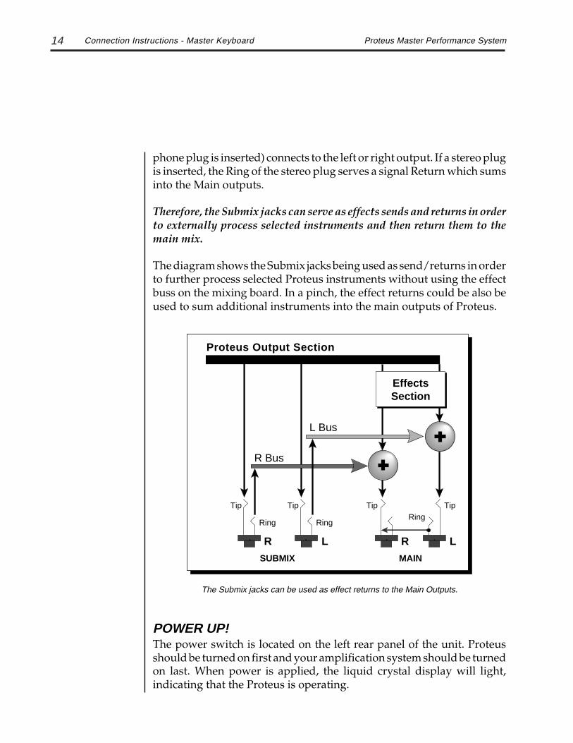
Outputs -Use a high quality amplification and speaker system such as akeyboard mixer and amplifier. The Right Main output jack serves as amono output when the left jack is not plugged in. Each of the SubmixOutputs are stereo jacks. The tip of each jack (accessed when a standard
See the PerformanceEdit section for detailedinformation on the splitkeyboard.
Proteus Master Performance System14
phone plug is inserted) connects to the left or right output. If a stereo plugis inserted, the Ring of the stereo plug serves a signal Return which sumsinto the Main outputs.
Therefore, the Submix jacks can serve as effects sends and returns in orderto externally process selected instruments and then return them to themain mix.
The diagram shows the Submix jacks being used as send/returns in orderto further process selected Proteus instruments without using the effectbuss on the mixing board. In a pinch, the effect returns could be also beused to sum additional instruments into the main outputs of Proteus.
POWER UP!The power switch is located on the left rear panel of the unit. Proteusshould be turned on first and your amplification system should be turnedon last. When power is applied, the liquid crystal display will light,indicating that the Proteus is operating.
Connection Instructions - Master Keyboard
Tip
Ring
Tip
Ring
Tip TipRing
SUBMIX MAIN
R L R L
R Bus
L Bus
Proteus Output Section
EffectsSection
The Submix jacks can be used as effect returns to the Main Outputs.

Proteus Master Performance System 15
the PROTEUS SOUND
The Proteus Sound
Memory
10100101001010100101001010101010010101001010
Digital/AnalogConverter
1011001
Amplifier
Basic Sampling System
Analog/DigitalConverter
10110011011001
-1V -2V3V-1V-2V3V1V
0V
3V
-3V
The Proteus, unlike many synthesizers, utilizes digital recordings of realinstruments for the basis of its sound. This is similar to a tape recorderexcept that in the Proteus, the sounds are permanently recorded ondigital memory chips.
To perform this modern miracle, sounds and instrument waveforms arefirst sampled into the Emulator III, our top of the line, 16 bit stereo digitalsampler. After the sounds and waveforms have been truncated, loopedand processed, they are masked into the Proteus ROM (Read OnlyMemory) chips.
Conceptually, the sampling process is very simple, as shown in the BasicSampling System diagram. As a sound wave strikes the diaphragm of amicrophone, a corresponding voltage is generated. To sample the sound,the voltage level is repeatedly measured at a very high rate and thevoltage measurements are stored in memory. To play the sound back, thenumbers are read back out of memory, converted back into voltages, thenamplified and fed to a speaker which converts the voltage back into soundwaves. Of course, playing back 32 channels at different pitches tends tocomplicate matters, but this is basically how it works. In Proteus, we haveleft out the Analog/Digital converter stage since the sounds are alreadysampled for you.

Proteus Master Performance System16

17Proteus Master Performance System
BASIC OPERATION
Basic Operation

18 Proteus Master Performance System
MAIN CONTROLS
Volume - Functions as the master volume control for all audio outputs. Note: For maximumdynamic range, set this control at full level.
Demo - Initiates the demo sequence. The sequence can be halted by pressing any front panelbutton. If a card containing a demo sequence is inserted, the sequence on the card will play.
ROM/RAM/Card Bank - Selects a bank of 100 presets as the active bank.
Master Edit - Contains parameters that affect the entire machine, not just certain presets. Anilluminated LED to the left of the button indicates that you are in the Master menu.
Performance Edit - Allows you to edit the Performance parameters such as: Quick Keyassignments, Effects settings, and Programmable MIDI commands. An illuminated LED to theleft of the button indicates that you are in the Performance Edit menu.
Preset Edit - Allows you to edit the parameters of a Preset. An illuminated LED to the leftof the button indicates that you are in the Preset Edit menu.
Transpose - Transposes the key of the instrument in half-step intervals. While theTranspose button is held down, a transposition is specified by pressing a keyboard key relativeto middle C up to +/- 12 semitones. The LED will be lit to indicate that a transposition is ineffect. Numeric keys can also be used to select transpositions. Press middle C while holding theTranspose button to return to normal tuning. Transpose does not affect notes received overMIDI.
Quick Key - Turns the Quick Key function On or Off. Quick Key allows single button presetchanges by pressing one of the preset select buttons 0-9. See Performance Edit.
Numeric Buttons 0-9 - Are used to enter Preset numbers within a bank, select Quick Keyassignments when Quick Keys are enabled, or select a Performance Map using the Perfor-mance Select button.
Performance Select - Selects Performances 0-9. Hold the button down and press one of thenumeric keys to select a new Performance Map.
VOLUMECARD
RAM
ROM
BANK
TRANSPOSE QUICKEY 0 1 2 3 4
PRESET
PERFORMANCE
MASTER
EDIT
DEMO
Main Controls

19Proteus Master Performance System
MAIN CONTROLS
Multi - Activates the Multi-Map in the current Performance Map including effect routingsand assignments. Multi allows Proteus to receive MIDI data on multiple channels. When Multiis Off, the MIDI mode (other than Multi) last specified in the Master menu is used.
Save/Copy Button - Allows you to: Save a Preset to a RAM or Card location when in Preset Edit Mode.
Press Copy/Save from within the Preset Edit menu. Select the new location and press Enter. Save a Performance Map to a RAM or Card location when in Performance Edit Mode.
Press Copy/Save from within the Performance Edit menu. Select the new location and press Enter. Copy a Bank of 100 Presets to the RAM or Card when not in an Edit Mode.
Press Copy/Save from the main menu. Select the desired bank copy function and press Enter. Copy effects parameters back and forth between a Preset and a Performance Map.
Press Copy/Save from within any effects menu. Select the new location and press Enter (see page 107). Copy a Quick Key to another location (see page 44).
Press Copy/Save from the Quick Key preset select screen. Select the desired destination and press Enter.
Compare - Selects between the edited and un-edited version of a preset while in Preset EditMode. The LED lights to indicate that the original un-edited version is currently selected andno further changes can be made until Compare is turned Off.
Enter - Used to initiate some operations within the Proteus. The red LED above the Enterbutton flashes to let you know that the Proteus is waiting for your response. Enter alsofunctions as a “Home” button, normally returning the cursor to the upper left corner of thedisplay (or the lower left in the main screen).
Inc / Dec Buttons - These two buttons increment or decrement the value of the currentlyselected parameter by one each time they are pressed.
Cursor - These two buttons move the cursor in either direction to the next parameter on thedisplay. (The cursor is a little flashing line underneath one of the parameters in the display.)Press one of the cursor buttons repeatedly until the cursor is underneath the desired parameter.
Data Entry Control - Used to change parameter values. The control increments ordecrements the current value one unit with each click.
5 6 7 8 9
ENTER
COMPARE
SAVE/COPY
PERFORMANCESELECT
<
DEC
INC
>CURSOR
MULTI
DATA
Main Controls

20 Proteus Master Performance System
BASIC OPERATION
Preset Selection
PRESET SELECTIONThe preset selection screen is shown below. This screen appears when theProteus is first powered-up and when the Master, Performance Edit, andPreset Edit menus are all Off.
C01 Vol127 Pan=P000 Grand Piano
There are several ways in which presets may be selected.
By rotating the data entry control, presets will be scrolled consecutivelyfrom 0-199 (0-299 with a memory card installed) when the cursor inunderneath the preset number.
The Increment/Decrement buttons increment or decrement the presetby one with each press when the cursor is underneath the presetnumber. If either button is held, the presets will rapidly scroll in theselected direction (inc=up, dec=down).
When not in Quick Key mode, presets within one of the three banksmay be selected by entering the desired preset number using thenumeric keys (0-9). Presets may be selected by entering a three digitnumber. To quickly jump to another bank, simply press the desiredbank button. The preset will be immediately selected.
When Quick Key mode is turned on (and the Quick Key LED is lit), anypreset may be selected by pressing a single numeric key (0-9). For moreinformation on Quick Key, see page 44.
Presets may be changed via a MIDI program change (if enabled).
Presets are organized into 3 banks:
CARD
RAM
ROM
BANK
Channel Volume
Preset Name
Channel Pan
Preset Number
MIDI Channel
ROM Presets
RAM Presets
Card Presets
0-99
100-199
200-299

21Proteus Master Performance System Basic Functions
BASIC OPERATION
MOVING THE CURSORThe Cursor is the little flashing line in the display which is used to identifywhich parameter is being modified. The Cursor keys are used to move theCursor around in the display.
C01 Vol127 Pan=P000 Grand Piano
< >CURSOR
MovesCursorBack
MovesCursor
Forward
To modify a parameter, press either the left or right cursor controlrepeatedly (or hold down the button) until the cursor is underneath thedesired parameter, then use the data knob, increment/decrement buttonsor numeric keys to change the number.
ENTERThe Enter button is used to confirm some selections (such as saving apreset) and also functions as a “home” button to return the cursor to theupper left corner of the display (in the preset selection screen, home is thelower line). The Enter LED flashes to indicate that Proteus is waiting foryour response.
INCREMENT/DECREMENT AND DATA ENTRY KNOBThe increment/decrement buttons and data entry knob allow you tochange value over the cursor. The increment/decrement buttons arehandy in that they allow you to fine tune the value since they add orsubtract one from the number with each pressing. If the increment/decrement buttons are held, they switch to a fast mode.

22 Proteus Master Performance SystemMIDI Channel Selection
BASIC OPERATION
The main screenshows the Preset,Volume and Paninformation for all 16MIDI channels. Asthe MIDI channel ischanged, the presetname, volume andpan positions willalso change.
The Volume Slideron the front panel isthe master volumecontrol and over-rides the channelvolume control.
MIDI CHANNEL SELECTIONThe channel number shown in the upper left corner of the main screen isthe channel on which the keyboard will transmit data to other MIDImodules and the channel on which Proteus will receive when in Polymode (the Basic Channel). Press either of the cursor buttons repeatedlyuntil the cursor is underneath the MIDI Channel number. Rotate the dataentry control (or use the inc/dec buttons) to select channels 1-16.
C01 Vol127 Pan=P000 Grand Piano
CHANNEL VOLUMEChannel volume controls how loudly the preset will play. When inMultiple preset mode (Multimode) it sets the volume of each of the MIDIchannels. Press either of the cursor buttons repeatedly until the cursor isunderneath the volume parameter. Rotate the data entry control (or usethe inc/dec buttons) to set the volume level from 0 to 127. This is the sameparameter as MIDI volume control #7, and changes made over MIDI willshow in the display.
C01 Vol127 Pan=P000 Grand Piano
CHANNEL PANPress either of the cursor buttons repeatedly until the cursor is under-neath the pan parameter. Rotate the data entry control (or use the inc/decbuttons) to set the pan from -7 to +7 or “P”. When “P” is selected, the panvalue specified in the preset is used. This is the same parameter as MIDIpan control #10, and changes made over MIDI will show in the display.
C01 Vol127 Pan=P000 Grand Piano
23Proteus Master Performance System Multi-Timbral Operation
BASIC OPERATION
MULTI-TIMBRAL OPERATIONMulti-timbral operation means that the Proteus can play more than onepreset at the same time. To access multiple presets on different MIDIchannels simultaneously, follow these instructions.
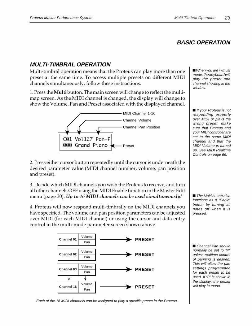
1. Press the Multi button. The main screen will change to reflect the multi-map screen. As the MIDI channel is changed, the display will change toshow the Volume, Pan and Preset associated with the displayed channel.
C01 Vol127 Pan=P000 Grand Piano
2. Press either cursor button repeatedly until the cursor is underneath thedesired parameter value (MIDI channel number, volume, pan positionand preset).
3. Decide which MIDI channels you wish the Proteus to receive, and turnall other channels OFF using the MIDI Enable function in the Master Editmenu (page 30). Up to 16 MIDI channels can be used simultaneously!
4. Proteus will now respond multi-timbrally on the MIDI channels youhave specified. The volume and pan position parameters can be adjustedover MIDI (for each MIDI channel) or using the cursor and data entrycontrol in the multi-mode parameter screen shown above.
MIDI Channel 1-16
Channel Volume
Channel Pan Position
Preset
Each of the 16 MIDI channels can be assigned to play a specific preset in the Proteus .
Channel 01Volume
Pan
Channel 03Volume
Pan
Channel 16Volume
Pan
Volume
PanChannel 02
PRESET
PRESET
PRESET
PRESET
Channel Pan shouldnormally be set to "P"unless realtime controlof panning is desired.This will allow the pansettings programmedfor each preset to beused. If “0” is shown inthe display, the presetwill play in mono.
If your Proteus is notresponding properlyover MIDI or plays thewrong preset, makesure that Proteus andyour MIDI controller areset to the same MIDIchannel and that theMIDI Volume is turnedup. See MIDI RealtimeControls on page 66.
The Multi button alsofunctions as a “Panic”button by turning allnotes off when it ispressed.
When you are in multimode, the keyboard willplay the preset andchannel showing in thewindow.

24 Proteus Master Performance SystemMemory Card
BASIC OPERATION
MEMORY CARDThe memory card is a convenientmethod for saving and transferringPresets and Performance Maps. In-sert the card firmly in the slot withthe label up as shown. A RAM cardstores 100 presets and 5 perfor-mance maps. Preset locations 200-299, and Performance Maps 5-9 arelocated on the RAM Card.
MEMORY CARD
PROTEUS
R A M C A R D
RAM cards may be write protected by moving the little switch on top ofthe card to the Protect position. If you try to save data to a card that is writeprotected, the display reads:
Sorry..This cardis protected...
If an un-initialized card is inserted into the Proteus , the display reads:
Not an E-mu cardUse it anyway?
Press Enter to initialize the RAM card (this erases the card).
COPY BANKThe Save/Copy button performs several functions depending in whichmodule (Master, Preset Edit, Performance) you are using. When in thepreset select mode the Save/Copy button allows you to copy an entirebank of 100 presets from ROM to RAM, ROM to Card, RAM to Card, orCard to RAM locations.
Card
UserRAM
FactoryROM
COPY
100 Presets 100 Presets
100Presets
RAM Cards can beused to store your ownpresets and maps. ROMcards contain prere-corded presets and se-quences. You cannotsave data to a ROM card.
If the RAM Card isdefective, the error mes-sage, “Cannot read card”will appear.
WARNING: Copyinga bank of presets erasesthe existing presets inthose 100 locations.Make sure that the desti-nation bank does notcontain presets that youwanted to keep.

25Proteus Master Performance System Master Edit Menu
MASTER EDIT MENU

26 Proteus Master Performance System

27Proteus Master Performance System
The Master menu contains functions that affect the overall operation ofthe Proteus. For example, changing the Master Tune will change thetuning of all the presets, not just the one currently displayed. All changesmade in the Master Edit menu (with the exception of Local Control) areremembered when the power is turned off.
TO ENABLE THE MASTER EDIT MENUPress the Master button, lighting the LED. The current screen will be theone most recently selected since powering up the Proteus. The cursor willappear underneath the first character of the screen heading on line one.
TO SELECT A NEW SCREENPress either cursor key repeatedly (or hold the cursor key) until the cursoris underneath the screen title heading. (You may also press the Enterbutton to return the cursor to “Home” position.) Rotate the data entrycontrol or use the increment/decrement buttons to select another screen.
TO MODIFY A PARAMETERPress either cursor key repeatedly (or hold the cursor key) until the cursoris underneath the parameter value. Rotate the data entry control or usethe increment/decrement buttons to change the value.
TO RETURN TO PRESET SELECT MODEPress the Master Edit button, turning off the LED.
MASTER EDIT FUNCTIONS
MASTER TUNEMaster Tune adjusts the overall tuning of all presets so that Proteus canbe tuned to other instruments. The master tuning range is ± 1 semitone in1/64th semitone increments. A master tune setting of “00” would indi-cate that the Proteus is perfectly tuned to concert pitch (A=440 Hz).
MASTER TUNE+63
Master Edit Menu
MASTER EDIT MENU

28 Proteus Master Performance System
TRANSPOSEThis function transposes the key of the Proteus keyboard in half-stepintervals. The transpose range is ±12 semitones or one octave. Transposeonly transposes notes played from the keyboard and sent out over MIDI.It does not transpose incoming MIDI data. This screen performs the samefunction as the front panel transpose button and changes made from thefront panel will be reflected in this display.
TRANSPOSE+00 semitones
GLOBAL BENDThis function sets the range of the pitch wheel (the left, spring-loadedwheel) only when it is routed to control pitch (in the Preset Edit menu). Themaximum pitch bend range is ± 12 semitones. This function only affectspresets which have their individual pitch bend range set to global.
GLOBAL BEND+- 12 semitones
GLOBAL VELOCITY CURVEIncoming velocity data can be modified by a velocity curve in order toprovide different types of dynamics in response to your playing or tobetter adapt to a MIDI controller. This function allows you to select oneof the four velocity curves or leave the velocity data unaltered (off). Globalvelocity curve only affects presets which have their individual velocitycurve set to global. For more information on the velocity curves, see page 64.
GLOBAL VEL CURVE4
Transpose
MASTER EDIT MENU
“Global” means thata parameter can applyto all presets. Presetsmay use a speciallydefined value insteadof the global value.

29Proteus Master Performance System Global Pressure Amount
GLOBAL PRESSURE AMOUNTKeyboard pressure or aftertouch is the pressure applied after the key isinitially pressed. What keyboard pressure actually controls is pro-grammed separately for each preset (in the Preset Edit menu). GlobalPressure Amount allows you to apply an overall scaling to the pressureamount programmed in each preset. Pressure has maximum effect whenthe value is set to 127.
GLOBAL PRESS AMT127
MIDI MODEThis function selects one of the four MIDI modes and the MIDI systemexclusive ID number.
Omni mode - Proteus responds to note information on all MIDIchannels and plays the preset currently displayed in the main screen.
Poly mode - Proteus only responds to note information received on thecurrently selected MIDI channel (on the preset selection screen) and playsthat channel’s associated preset.
Multi mode - Proteus responds to data on any combination of MIDIchannels and plays the specific preset associated with each of the MIDIchannels. This function is duplicated with the front panel Multi button.
Mono mode - Proteus responds to data on any combination of MIDIchannels but plays each channel monophonically. If a new note is playedbefore the last note is released, the envelopes will not be retriggered(legato). Mono mode is particularly useful with alternate controllers suchas MIDI guitars, wind controllers, etc.
ID number - This function allows an external programming unit todistinguish between multiple Proteus units. In the case of multipleProteus units, each Proteus should have a different ID number.
MIDI MODE IDPoly 00
MASTER EDIT MENU
Warning: Presetswill not be transferredbetween two Proteus'unless the ID numbersof both units match.

30 Proteus Master Performance SystemMIDI Mode Change
MASTER EDIT MENU
MIDI MODE CHANGEThis function selects whether or not MIDI mode change commands areaccepted or ignored when received over MIDI (see MIDI mode on theprevious page).
MIDI MODE CHANGEDisabled
MIDI ENABLEWhen in MIDI Multi mode, this function allows you to turn each channelOn or Off. This is useful when you have other MIDI devices connectedand do not want the Proteus to respond to the MIDI channels reserved forother devices. MIDI Enable only operates in Multi mode.
MIDI ENABLEchannel: 01 On
LOCAL CONTROLWhen on, the Proteus keyboard controls the internal sound generatorsand sends out MIDI data about which keys are being played. TurningLocal Control Off, disconnects the internal sound generators from thekeyboard but Proteus still sends and receives MIDI data. Local Control isoften turned Off when recording into a MIDI sequencer (set sequencer toEcho Thru ). Local Control is always turned On at power-up.
LOCAL CONTROLOn

31Proteus Master Performance System Receive Program Change
MASTER EDIT MENU
RECEIVE PROGRAM CHANGEMIDI also carries program (preset) change information from one synthe-sizer to another. When Receive Program Change is turned On, programchange messages are received over the MIDI line. When turned Off, allprogram change messages are ignored.
RECV PROG CHANGEOn
SEND PROGRAM CHANGEWhen Send Program Change is turned On, program change messages aretransmitted over the MIDI line to other devices. When turned Off, theprogram change messages are not transmitted.
SEND PROG CHANGEOn
SEND CONTROLLERSContinuous Controller data from the Pitch Wheel, Modulation Wheel andPressure is also transmitted over MIDI. When Send Controllers is turnedOn, continuous controller messages are transmitted over the MIDI cableto other devices. When turned Off, continuous controller messages arenot transmitted.
SEND CONTROLLERSOn
With Send ProgramChange Off, presetchange commandswill not be sent fromQuick Keys, Multi-Mapselections or individualpreset changes.
MIDI programchanges are only sentas a result of keypresses (numeric andinc/dec buttons), andnot through data entryknob selection.

32 Proteus Master Performance System
MASTER EDIT MENU
MIDI Controller Assign
MIDI CONTROLLER ASSIGNThe Proteus Master Performance System allows you to assign up to fourrealtime controllers. A controller could be the modulation wheel, thefootpedal or a realtime controller from another MIDI keyboard. In thisscreen, you select the continuous controller numbers that Proteus willtransmit and receive. What effect the controller will have is programmedseparately for each preset. The first controller is dedicated to the ProteusModulation Wheel (right wheel). If controller 001 is selected for theModulation Wheel then Proteus will transmit the Modulation Wheel dataon controller 001 (Incoming MIDI data on controller 001 will also bereceived and will have the same effects as moving the wheel). The otherthree controllers are assigned a letter B-D. The Mod. wheel can beassigned a MIDI realtime controller number from 0-120. Each controllerletter can be assigned to a MIDI realtime controller number from 01-31.
CONTROLLER #MOD:001 B:02
Next Screen:
CONTROLLER #C:03 D:04
The MIDIController
Numbers areAssigned
Here.
What theControls
Actually Do isProgrammedin the Preset.
ModLFO Amount
MASTER PRESET
MIDIController01 - Mod
BLFO Speed
CAttack Time
MIDIController
09 - B
MIDIController
04 - C
The MIDI spec allowsup to 128 controllers perchannel. This featurelets you to connect fourof them any way youwant.
If controller numbers7 or 10 are selected,they will override thestandard MIDI volumeand pan controlroutings and Proteuswill not respond to MIDIVolume and Panchanges. For more in-formation, see MIDIRealtime Controls onpage 66.

33Proteus Master Performance System Pedal Control
MASTER EDIT MENU
PEDAL CONTROLThis screen allows you to dedicate the footpedal as a volume control forthe current preset or to assign it to Controller B to be used as a generalpurpose controller. When the footpedal is assigned to Controller B, thedata will also be transmitted over MIDI (on the realtime control channelselected for Controller B in the previous screen).
PEDAL CONTROLVolume
MIDI FOOTSWITCH ASSIGNLike the MIDI Controllers, MIDI footswitches can be assigned to MIDIfootswitch numbers. Footswitches can be assigned numbers from 64-79.Destinations for the footswitch controllers are programmed in the PresetEdit menu. The Local footswitch number will be transmitted over MIDIwhen Proteus's footswitch is depressed. Additionally, MIDI footswitchdata received on the specified controller number will be routed to theLocal destination as programmed in the Preset Edit menu.
FOOTSWITCH #Local:64
Footswitch numbers 2 and 3 set the footswitch numbers that will bereceived by Proteus from an external MIDI controller (such as anotherMIDI keyboard).
FOOTSWITCH #2:65 3:66
When the pedal isassigned to Volume,the pedal data is alsotransmitted over MIDIcontinuous controllerchannel 7.
- Transmitted and Received over MIDI
- Received over MIDI

34 Proteus Master Performance System
MASTER EDIT MENU
This chart shows how MIDI preset changes can be re-mapped. In this example, program changes10-29 (darkened area) have been re-mapped. All other programs will be selected normally. Anincoming program change of 26 is re-mapped through the table above to select program 12.
EFFECTS TRANSITIONSometimes when the type of effect is changed, an audible “ping” may beheard. This function allows you to select whether or not the audio istemporarily muted when switching presets (effects). Only the effect busswhose effect is changed will be muted.
FX TransitionMute
MIDI PROGRAM -> PRESETIncoming MIDI program changes can be translated into a differentnumbered preset. This is a handy feature when you want a specific presetnumber sent from a MIDI controller to be linked with a specific preset onthe Proteus. Simply selecting a preset on the MIDI controller can auto-matically call up the proper Proteus preset. Any of the presets in Proteuscan be mapped to any incoming MIDI program change number. Thisfeature allows you to call up the presets 128-299, which are not normallyaccessible over MIDI. There are four MIDI Program -> Preset maps in theProteus.
MIDI PROG>PRESET#4: 026 -> 012
SelectedProgram
MappedProgram
0 1 2 3 4 5 6 7 8 9
00
10
20
30
40
50
60
70
80
90
100
110
120
00 01 02 03 04 05 06 07 08 09
30 31 32 33 34 35 36 37 38 39
40 41 42 43 44 45 46 47 48 49
50 51 52 53 54 55 56 57 58 59
60 61 62 63 64 65 66 67 68 69
70 71 72 73 74 75 76 77 78 79
80 81 82 83 84 85 86 87 88 89
90 91 92 93 94 95 96 97 98 99
100 101 102 103 104 105 106 107 108 109
110 111 112 113 114 115 116 117 118 119
120 121 122 123 124 125 126 127
44 191 50 01 15 88 151 78 99 88
34 73 106 55 43 75 120 121 18012
Effects Transition
MIDI Program ->Preset maps areselected as part of aPerformance Map(see page 54).
Note: On somesynthesizers Preset00 is called Preset 01with a correspondingdifference through allthe numbers.

35Proteus Master Performance System Send MIDI Data
SEND MIDI DATAThis function will send MIDI System Exclusive data to the MIDI Out portof the Proteus. The MIDI data can either be sent to a computer/sequenceror to another Proteus. Using the cursor key and the data entry control,select the type of MIDI data you wish to transmit. The choices are:
Master Settings: Transmits all parameters in the Master menu excepttuning table, program/preset map, remote, calibrations and viewingangle.
Program/ Preset Map: Transmits only the program/preset maps.
Tuning Table: Transmits only the user tuning table.
Performance Maps: Transmits all the performance maps.
All Card Presets: Transmits all the memory card presets.
All ROM Presets: Transmits all the ROM (factory) presets.
All RAM Presets: Transmits all the RAM (user) presets.
Any Individual Preset: Transmits only the selected preset.
After selecting the type of data, the Enter LED will be flashing. Press theEnter button to confirm the operation. To receive MIDI data, simply sendthe MIDI data into Proteus from another Proteus or your sequencer.
SEND MIDI DATA000 Stereo Piano
To Record MIDI Data into a Sequencer or another Proteus1. Connect MIDI Out of the Proteus to the MIDI In of the receiving device.2. Set up the Sequencer to receive MIDI System Exclusive data.3. Place Sequencer into Record Mode, then Send MIDI Data.
To Receive MIDI Data from a Sequencer or another Proteus1. Connect MIDI Out of the sending device to the MIDI In of Proteus.2. Simply play back the sequence into Proteus. (If you are sending from another Proteus, just Send MIDI Data.)
MASTER EDIT MENU
Warning: Whentransferring SysEx datafrom one Proteus to an-other, the ID numbers ofboth units must match.
When reloading MIDIdata, the ID number ofthe data and the Pro-teus must both match.
Warning: Whentransferring presetbanks back and forthfrom the Proteus to acomputer, the datashould be recorded asyou would a regular se-quence. Sending thedata in one huge chunkwill choke the Proteus.
36 Proteus Master Performance System
MASTER EDIT MENU
User Key Tunings
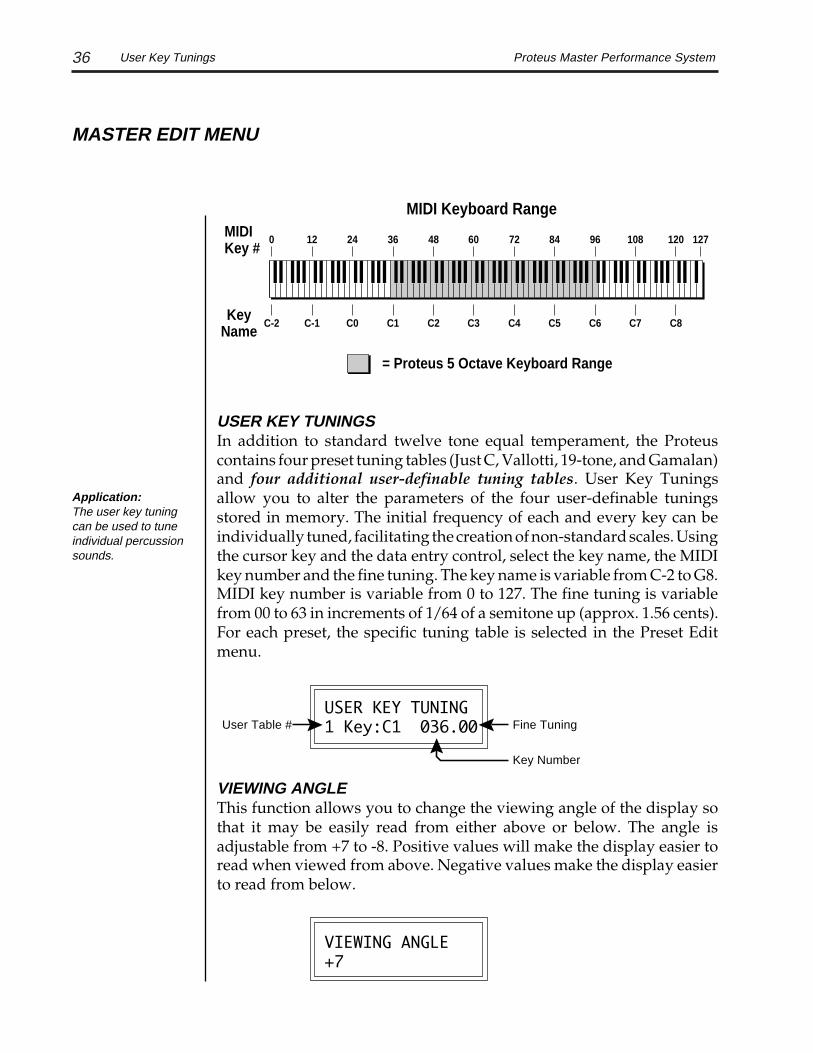
USER KEY TUNINGSIn addition to standard twelve tone equal temperament, the Proteuscontains four preset tuning tables (Just C, Vallotti, 19-tone, and Gamalan)and four additional user-definable tuning tables. User Key Tuningsallow you to alter the parameters of the four user-definable tuningsstored in memory. The initial frequency of each and every key can beindividually tuned, facilitating the creation of non-standard scales. Usingthe cursor key and the data entry control, select the key name, the MIDIkey number and the fine tuning. The key name is variable from C-2 to G8.MIDI key number is variable from 0 to 127. The fine tuning is variablefrom 00 to 63 in increments of 1/64 of a semitone up (approx. 1.56 cents).For each preset, the specific tuning table is selected in the Preset Editmenu.
USER KEY TUNING1 Key:C1 036.00
VIEWING ANGLEThis function allows you to change the viewing angle of the display sothat it may be easily read from either above or below. The angle isadjustable from +7 to -8. Positive values will make the display easier toread when viewed from above. Negative values make the display easierto read from below.
VIEWING ANGLE+7
C-2 C-1 C0 C1 C2 C3 C4 C5 C6 C7 C8
= Proteus 5 Octave Keyboard Range
MIDI Keyboard RangeMIDIKey #
KeyName
0 12 24 36 48 60 72 84 96 108 120 127
Application:The user key tuningcan be used to tuneindividual percussionsounds.
Fine Tuning
Key Number
User Table #

37Proteus Master Performance System
MIDI IN ACTIVITYThis function allows you to monitor incoming MIDI data which mayprove helpful in solving MIDI interconnection problems. The lower linereads out MIDI data which was last received. Most MIDI messages aredisplayed, including MIDI Clocks, SysEx and Active Sensing messages.
MIDI In ActivityC01 NOff A3 064
STARTUP MESSAGEThis feature allows you to program your own startup message which willappear whenever the keyboard is first turned on. Messages can be up to15 characters long.
STARTUP MESSAGEYour Name Here
CALIBRATIONThe calibration function allows you to recalibrate the pressure, pedal,pitch wheel and modulation wheel. User calibration is desirable for anumber of reasons. You may want to recalibrate the pressure to yourpersonal taste or you may own a pedal which doesn't seem to workcorrectly. Simply recalibrate the pedal function and you're back inbusiness. Over time analog components used in the pitch and mod. wheelcircuitry may drift. The calibration function allows you to correct theproblem yourself and save a service call.
CALIBRATIONPressure Min
MASTER EDIT MENU
MIDI In Activity
Note
VelocityChannel #
Data Type

38 Proteus Master Performance SystemCalibrations
MASTER EDIT MENU
To Calibrate Pressure:1) Press either cursor button to move the cursor to the lower line of thedisplay. The enter LED will be flashing.
2) Press a key on the keyboard slightly down to set the minimum amountof pressure. Set the minimum pressure hard enough so that no pressuremodulation will be applied with normal playing. When you have theproper amount of minimum pressure, press enter.
3) Press the increment button to change the display to pressure max.
CALIBRATIONPressure Max
4) Press a key on the keyboard down hard to set the maximum amount ofpressure. Set this amount for the hardest you expect to press on thekeyboard. When you have the proper amount of maximum pressure,press enter.
5) Press either cursor button to move the cursor back to the upper line ofthe display to quit.
To Calibrate the Pedal:1) Move the cursor to the lower line of the display. Use the data entrycontrol or the inc/dec buttons to select “Pedal Min”.
2) Plug in a control pedal (E-mu part number SW 323 or equivalent) to therear panel jack and move it to its up position (Off). Press enter.
3) Use the data entry control or the inc/dec buttons to select “Pedal Max”.Depress the pedal to its lowermost position (On), then press enter.
The control pedal should be internally wired as shown above.
10KTip
Sleeve

39Proteus Master Performance System
MASTER EDIT MENU
To Calibrate the Modulation Wheel:1) Move the cursor to the lower line of the display. Use the data entrycontrol or the inc/dec buttons to select “Mod Min”.
2) Rotate the modulation wheel all the way back toward you. Press enter.
3) Use the data entry control or the inc/dec buttons to select “Mod Max”.Rotate the modulation wheel fully forward away from you. Press enter.
To Calibrate the Pitch Wheel:1) Move the cursor to the lower line of the display. Use the data entrycontrol or the inc/dec buttons to select “Pitch Center”. Press enter.
2) Use the data entry control or the inc/dec buttons to select “Pitch Min”.Move the pitch wheel all the way back toward you and while holding itin this position, press enter.
3) Use the data entry control or the inc/dec buttons to select “Pitch Max”.Move the pitch wheel fully forward away from you and while holding itin this position, press enter.
Calibrations

40 Proteus Master Performance System

41Proteus Master Performance System
PERFORMANCE EDIT MENU
Performance Editing

42 Proteus Master Performance System

43Proteus Master Performance System What are Performance Maps?
WHAT ARE PERFORMANCE MAPS?A Performance Map is a set of parameters which can be used to configurethe Proteus and your other MIDI gear which you may want to associatewith a particular song or song set. There are five Performance Maps inProteus (0-4) and you can store another five Performance Maps on theRAM Card (5-9).
This chart shows the contents of a single Performance Map.
DEFINITIONSZONES - A zone is simply a keyboard range which you can define. A zonecan be any size from 1 to 127 keys wide. There are four possible Zoneswhich can overlap (for layering) or lie adjacent to each other (for splitkeyboards).
MULTIMODE - Allows the Proteus to receive on 16 MIDI channelssimultaneously.
MULTIMAPS - A Multimap defines the Preset and its associated Volumeand Pan position for each of the 16 MIDI channels for multitimbralsequencing. Each Performance Map can store one Multimap.
PERFORMANCE EDIT MENU
10 Quick Key Assignments (0-9)
Multimode Effects Assignments
A, B, Dry, Sub, Preset (for each channel)
A, B - Effect Type and Amount
Transmits up to 5 MIDI Commands (when a Performance Map is selected)
Program Change, Song Select, Song Start, Song Stop, Volume, Pan, Plus 1 User-Definable, 320 Byte String
MIDI Receive Information for each MIDI Channel
Volume, Pan, Preset and Program Change On/Off
PERFORMANCE MAP
Quick Key Defines up to 4 Keyboard ZonesEach Zone: Has an associated internal Preset, Volume, Pan Can transmit a MIDI Volume and Pan value Can be transmitted on a separate MIDI channel Can transmit a MIDI program change command
Selecting a QuickKey will change the cur-rent Multi-Map Presetsto the Preset settingsprogrammed for thatQuick Key.

44 Proteus Master Performance System
TO SELECT A PERFORMANCE MAP
Select Performance Number (0-9)2)
QUICK KEY 0
PRESET
PERFORMANCE
MASTER
EDIT
ENTER
COMPARE
SAVE/COPY
PERFORMANCESELECT1 2 3 4 5 6 7 8 9
Press and Hold1)
P E R F O R M A N C E M A P# 2 T a k e i t A w a y
Release Select Button3)
QUICK KEYSWhen the Quick Key function is enabled and the LED is lit, selectedpresets can be accessed by pressing a single button (0-9). The Data Entryknob and the inc/dec buttons can still be used to select programs whenin Quick Key mode.
Quick Keys
Select Quick Key (0-9)2)
QUICK KEY 0
PRESET
PERFORMANCE
MASTER
EDIT
ENTER
COMPARE
SAVE/COPY
PERFORMANCESELECT1 2 3 4 5 6 7 8 9
Turn Quick Key On1)
C 0 1 V o l 1 2 7 P a n = P0 0 0 S t e r e o P i a n o
PERFORMANCE EDIT MENU
KEY0 Z1 C-2 ->G8000 Grand Piano
QUICK KEY COPY1. Press the Performance Edit button.2. Find the Quick Key Select screen and choose the Quick Key to copy From .3. Press SAVE/COPY.4. Choose the Quick Key to copy To and press Enter.
Performance Mapsare selected when thePerformance Selectbutton is RELEASED.
Quick Key-PresetAssignment ShortcutAssigns a preset tozone #1. Erases zones2-4.
1. Turn Quick Key On.
2. Select the preset youwish to assign with theData Entry knob.
3. Hold down the Enterbutton and press thedesired Quick Key.
4. The display will con-firm the operation,“Quick Key #0-9, OK”.
Warning: Quick Keysare not saved until thecurrent PerformanceMap is saved (see page45).

45Proteus Master Performance System Performance Edit Menu
The Performance Edit menu contains functions that allow you to programyour own Performance Maps and Quick Keys.
TO SELECT A PERFORMANCE MAPPress and hold the Performance Select button. The current PerformanceMap will be shown in the display. Pressing one of the numeric buttonswhile holding Performance Select selects a new Performance Map. Theselection is executed when the Performance Select button is released.
TO ENABLE THE PERFORMANCE EDIT MENUPress the Performance Edit button, lighting the LED. The current screenwill be the one most recently selected since powering up the Proteus. Thecursor will appear underneath the first character of the screen heading.
TO SELECT A NEW SCREENPress either cursor key repeatedly (or hold the cursor key) until the cursoris underneath the screen heading. (You may also press the Enter buttonto return the cursor to “Home” position.) Rotate the data entry control oruse the increment/decrement buttons to select another screen.
TO MODIFY A PARAMETERPress either cursor key repeatedly (or hold the cursor key) until the cursoris underneath the parameter value. The data entry control, the incre-ment/decrement buttons or the numeric keys can be used to change thevalue.
TO SAVE A PERFORMANCE MAPWhile in the Performance Edit menu, press the Save/Copy button. Usethe data entry knob, the increment/decrement buttons or the numerickeys to select the map location (0-4 Internal, 5-9 RAM Card), then pressEnter.
TO COPY A PERFORMANCE MAPSelect the Performance Map you want to copy. Press Performance Edit,then Save/Copy. Select the new map location (0-4 Internal, 5-9 RAMCard), then press Enter.
TO RETURN TO PRESET SELECT MODEPress the Performance Edit button, turning off the LED.
PERFORMANCE EDIT MENU
Changes made tothe performance mapwill be lost when thepower is turned offunless the map hasbeen saved.
If you are in theQuick Key selectscreen (see previouspage) the Quick Keywill be copied insteadof the PerformanceMap.

46 Proteus Master Performance SystemPerformance Name
PERFORMANCE NAMEPerformance Name allows you to name each of the performance mapswith a name of up to 10 characters. Position the cursor under the characterlocation and use the keyboard, data entry control or increment/decre-ment buttons to change the character. The chart below shows the key-board character assignment.
PERFORMANCE NAMEMap1 My Song
02
3
57
8
:<
>
?A
C
DF
H
JK
M
OP
R
TV
W
Y[
¥
^`
b
ce
g
hj
l
no
q
st
v
xz
<-
+,
.
&'
)
blank
"$
46
9;
=@
B
EG
IL
N
QS
UX
Z
]_
ad
f
ik
mp
r
uw
y|->
-/
1(
*
!#
%
36 48 60 72 84 962412
MIDI Note Numbers
QUICK KEY KEYBOARD ZONE ASSIGNMENTSFor each Quick Key in a Performance Map, you may define up to fourzones (keyboard ranges) across the keyboard, each containing a differentProteus preset. Zones may overlap for stacking presets or lie adjacent toone another to create split keyboards. Place the cursor under the appro-priate parameter and change the Quick Key Number, Zone Number,Keyboard Range and the Preset using the data entry control, inc/decbuttons or numeric keys. As the Quick Key or Zone is changed, thedisplay will change to show the Key Range and Preset associated with thedisplayed Quick Key or Zone.
KEY1 Z1 C-2 ->G8000 Grand Piano
Quickey 0-9
Keyboard Zone 1-4
Key Range
Preset
An easy way to as-sign a preset to Zone 1of a Quick Key withoutgoing into the Perfor-mance Edit module…
1. Turn Quick Key On2. Select the Preset
you wish to assign.3. Press and hold the
Enter button, thenpress the Quick Keybutton you want.
4. REMEMBER TOSAVE THE PER-FORMANCE MAP!

47Proteus Master Performance System Zone MIDI Channel Assignments
PERFORMANCE EDIT MENU
ZONE MIDI CHANNEL ASSIGNMENTSFor each Quick Key, each of the four zones can be programmed totransmit on a different MIDI channel. If Off is selected, that zone will beturned Off for MIDI transmission AND keyboard control. Place thecursor under each zone's channel number and select the MIDI channelnumber (or Off) using the data entry control, inc/dec buttons or numerickeys.
CH:1 2 3 4 01 02 Off 16
ZONE VOLUME ASSIGNMENTSThis screen allows you to adjust the volume of each of the four zones. Thisfunction sets the volume of the internal sounds on the four zones. A MIDIvolume message is also sent for each zone when a Quick Key is selected(unless the channel select for that zone is turned off). Place the cursorunder each zones volume parameter and adjust the volume using the dataentry control, inc/dec buttons or numeric keys.
VOL1 2 3 4 127 100 075 120
The keyboard can be split or layered for internal sounds and to control external MIDI devices.In the diagram above, only 3 of the 4 possible zones are being used.
MIDI Channel Number
Zone Number
MIDI Channel: 01Volume: 088Pan: -7Octave: +0Wheel Enable: OnMod. Enable: OnPres. Enable: OffFtSw Enable: OnPedal Enable: OffProg. Change: OffPreset: 22
Inte
rna
l
MIDI Channel 5Volume: 100Pan: +2Octave: +1Wheel Enable: OnMod. Enable: OnPres. Enable: OnFtSw Enable: OffPedal Enable: OffProg. Change: 025Preset: 001
Inte
rna
l
MID
I O
ut MIDI Channel 2
Volume: 110Pan: +0Octave: +0Wheel Enable: OnMod. Enable: OnPres. Enable: OnFtSw Enable: OnPedal Enable: OffProg. Change: 127Preset: Default (099)
MID
I O
ut
MIDI OnlyInternal Only MIDI & Internal
MID
I O
ut
MIDI Send: Off MIDI Send: On MIDI Send: On
ZONE 3ZONE 1 ZONE 2
Selecting presetDefault (099) turnsthe internal soundsOff.
Zone Volume
Zone Number

48 Proteus Master Performance System
PERFORMANCE EDIT MENU
Zone Pan Assignments
ZONE PAN ASSIGNMENTSThis screen allows you to adjust the stereo pan position of each of the fourkeyboard zones. A MIDI pan message is also sent for each zone when aQuick Key is selected (unless the channel select for that zone is turned off).Place the cursor under each zones Pan parameter and adjust the panposition using the data entry control, inc/dec buttons or numeric keys.When Pan is set to “P” the pan settings in the preset will be used.
PAN1 2 3 4 =P -7 +7 =P
ZONE OCTAVE TRANSPOSEThis function allows each keyboard zone to be transposed up or downthree octaves in octave increments. Notes transmitted over MIDI will alsobe transposed. Place the cursor under the transpose parameter for eachzone and change the transposition using the data entry control, inc/decbuttons or numeric keys. A setting of “0” indicates no transposition.
OCT1 2 3 4 +0 -3 +3 +0
ZONE CONTROLLER ENABLEThis function allows you to enable or disable the various continuouscontrollers for each keyboard zone. MIDI information will also be en-abled or disabled. Place the cursor under the controller type and changeit using the data entry control, inc/dec buttons or numeric keys.
CTL 1 2 3 4PWh On Of On Of
ZONE MIDI SEND
Zone Pan
Zone Number
Zone Octave Transpose
Zone Number
Controller
Zone Number
Status of Controllerfor each Zone
PWH = Pitch WheelMod = Modulation WheelPrs = Pressure (Aftertouch)FSw = FootswitchPed = Pedal

49Proteus Master Performance System
PERFORMANCE EDIT MENU
Zone MIDI Send
This screen allows you turn MIDI transmission On or Off for each of thefour keyboard zones. Turning a zone Off inhibits all MIDI data associ-ated with the Quick Key such as note data, program change data, volume,pan and other controller data. The internal preset associated with thezone will be played and controlled normally.
SEND1 2 3 4 On Of On Of
ZONE MIDI PROGRAM CHANGE ASSIGNMENTSEach zone can be programmed to send out a MIDI Program Changecommand whenever a Quick Key is selected. The program change com-mand will be sent on the MIDI channel selected in the Zone MIDI ChannelAssignment screen (previously described). Place the cursor under eachzones program change parameter and change the program change com-mand (preset change) using the data entry control, inc/dec buttons ornumeric keys. When Off is selected, no program change command will betransmitted for that zone.
PRG1 2 3 4 Off 127 004 Off
EFFECT A (for Multimode)This function allows you to select which effect is assigned to effect buss A.In addition to several types of reverb, the A effects consist of other stereotime delay effects such as delays, choruser, phase shifters, etc. (see theeffects section for details).
FXA:Hall 2Decay Time: 200
Zone Number
MIDI Program Change Command
Zone Number
MIDI Enable On/Off
Effect type can alsobe changed via MIDIrealtime controller com-mands.
ControllerFXA = 82FXB = 83
See the charts on pages140 and 141

50 Proteus Master Performance System
PERFORMANCE EDIT MENU
Multimode Effect B
EFFECT B (for Multimode)This function allows you to select which effect is assigned to effect bussB. The B effects consist of various delays, chorusers, phase shifters, fuzzesand even a ring modulator (see the effects section for details).
FXB:StereoFlangeLFO Rate 050
EFFECTS AMOUNTThis function allows you to adjust the percentage of wet and dry signals(processed and unprocessed) with 100% being only processed signal.Additionally, the B->A parameter allows you to adjust the amount ofeffect B which is fed through effect A. If B>A is set one value above 100%,“Only” is displayed and the B amount changes to Off. This disconnectseffect B from the main outputs and routes all of the effect B signal througheffect A.
FX AMOUNT A:75%B>A:100% B:30%
Effect type can alsobe changed via MIDIrealtime controller com-mands.
ControllerFXA = 82FXB = 83
See the charts on pages140 and 141
The FX amounts canalso be changed viaMIDI realtime controllercommands.
ControllerA = 84B = 85B>A = 86
See the charts on pages140 and 141
For detailed explana-tions of each effect, seethe effects chapter in thismanual.
Block diagram of the Proteus effects section showing multiple channel effect routing. Eachchannel can be assigned to the A, B, Dry or Submix buss, or can be assigned to a buss as
programmed in the preset.
L
R
L
R
EFFECTA
Amount
EFFECTB
Amount
SubmixOutputs
MainOutputs
OutputBusses
BA
B
A
Dry
Sub.Outputs
MIDI Channel 1
MIDI Channel 2
MIDI Channel 3
MIDI Channel 4
MIDI Channel 16
MIDI Channel 5
PRESET

51Proteus Master Performance System
PERFORMANCE EDIT MENU
Multimode Effect Assign
MULTIMODE EFFECT ASSIGNFor each of the 16 MIDI channels, you may select one of the two availableeffects busses, have the channel remain dry (no effects) or route thechannel to the submix outputs. Selecting Preset allows the assignmentselected in the preset to be used. The type of effects used and theiramounts are selected in the previous screens.
EFFECT ASSIGNMIDI Ch04:Preset
MULTIMODE PRESET-VOLUME-PAN ASSIGNMENTThis function allows you to set the Preset, Volume and Pan position foreach of the 16 MIDI channels. These settings are only used when Multi-Mode is enabled. Place the cursor under the appropriate parameter andchange the MIDI Channel Number, Volume, Pan Position and PresetNumber using the data entry control or increment/decrement buttons.As the channel is changed, the display will change to show the preset,volume and pan parameters associated with the displayed channel.
C01 Vol127 Pan+0000 Grand Piano
MIDI MULTIMODEThis function selects whether Proteus responds polyphonically or mono-phonically when in Multi mode. Polyphonic mode is the normal setting- chords are possible and channels are used as needed. Monophonic modeis sometimes useful with MIDI guitar controllers - each MIDI channel canonly play one note.
MIDI MULTI MODEPolyphonic
Channel Pan shouldnormally be set to "P"unless realtime controlof panning is desired.This will allow the pansettings programmed foreach preset to be used.
The keyboard willplay the preset shownin the preset assign-ment screen last seen.
MIDI Channel 1-16
Channel Volume
Channel Pan Position
Preset

52 Proteus Master Performance System
PERFORMANCE EDIT MENU
Receive Program Change
RECEIVE PROGRAM CHANGEThis function lets Proteus either utilize or ignore incoming MIDI programchange commands for each channel. Note that MIDI can only selectpresets 000-127. Presets 128-299 can either be selected manually or overMIDI using the preset mapping function “MIDI PROGRAM > PRESET”.See page 34 for more information on the Program-> Preset Map.
RECV PROG CHANGEchannel:01 On
MIDI COMMAND 1-4This function allows you to transmit up to four MIDI commands when aPerformance Map is selected (not to be confused with a Quick Keyselection). The MIDI commands include:
Program Change ....... Value and ChannelSong Select ............... Song Number and ChannelSong Start .................. Song Number and ChannelSong Stop .................. Song Number and ChannelVolume ....................... Value and ChannelPan ............................. Value and Channel
MIDI COMMAND #1Ch01 ProgChg 000
Value (song number, etc.)
Type of Command
MIDI Channel 1-16
MIDI Command # 1-4

53Proteus Master Performance System
PERFORMANCE EDIT MENU
Record User Data
RECORD USER DATAThis function allows you to record a string of MIDI data up to 320 bytesin length. This data will be transmitted when the Performance Map isselected. The MIDI data can be virtually anything; SysEx data, controllerdata, even synthesizer patch data if the file is not too large.
RECORD USER DATAStart
To Record MIDI User Data:1. Connect MIDI Out of another MIDI device to the MIDI In of Proteus.2. Move the Cursor under Start and press Enter.3. Send data from the MIDI device (play keys, etc.). Press Enter to Stop.
To Playback MIDI User Data:1. Select the Performance Map.
EDIT USER DATAThis function allows you to edit a string of MIDI data up to 320 bytes inlength. You can edit data which was recorded using the Record Datafunction above or enter MIDI data manually. Any hexadecimal value canbe entered. Proteus does not check the data for accuracy, so check yourMIDI data carefully if unexpected results occur. Place the cursor under-neath the byte locations and use the data entry knob to change values.Place the cursor underneath the arrows (< >) and rotate the data entryknob in order to scroll back and forth through the MIDI data. Setting thedata value below 00 deletes the byte location. Pressing the Enter buttoninserts a new byte location to the left of the cursor position.
EDIT USER DATA[F0 18 04 00 03>
The user data istransmitted in onequick dump when aperformance map isselected. Continuouslychanging values suchas pitch wheel data willnot be recorded cor-rectly as they wouldinto a sequencer.

54 Proteus Master Performance System
PERFORMANCE EDIT MENU
MIDI Program -> Preset
MIDI PROG ->PRESETThis function selects one of the four MIDI Program to Preset Maps(programmed in the Master Edit menu) or turns the Program->Presetmaps Off. The MIDI bank select command is disabled (transmission andreception) whenever a Program->Preset map is selected. For more infor-mation on the MIDI Bank select command see the MIDI specification atthe back of this manual.
MIDI PROG>PRESET 1

PROGRAMMING BASICS
55Proteus Master Performance System Programming Basics
PROGRAMMING BASICS

PROGRAMMING BASICS
56 Proteus Master Performance System

PROGRAMMING BASICS
57Proteus Master Performance System
This section of the manual covers basic synthesizer operations (which areapplicable to many types of synthesizer, not just Proteus), as well asseveral functions and concepts unique to Proteus.
Your initial involvement with the Proteus will most likely consist of usingthe existing presets and selecting MIDI channels. While the factorypresets are very good, there are probably some things you would like tochange, perhaps the LFO speed, the attack time, or the type of effectsprocessing. You may also want to make your own custom presets usingcomplex modulation routings. Entirely new sounds can be created bycombining the attack portion of one sound with the body of anothersound or by combining the digital waveforms with sampled sounds.There are 200 (100 internal, 100 card) locations available to store your owncreations or edited factory presets. Best of all, it’s easy to edit or create newpresets using the Preset Edit menu.
General Information
PROGRAMMING BASICS
This block diagram shows the layout of the Proteus. Because of the extensive modulationcontrols, Proteus is able to synthesize new sounds as well as emulate traditional instruments.
LFO 1
Amount Freq.
LFO 2
Amount Freq.
AuxiliaryDAHDSR
AmtAtk Dec Rel
Pan
R
L
R
L
Level
Level
VolumeAHDSR
Atk Dec Rel
DCA
DCA Pan
Atk Dec Rel
VolumeAHDSR
Realtime Modulation Sources
X-Fade
PrimaryInstrument
Pitch
Modulation Destinations
LFO 2AUXILIARYENVELOPELFO 1
MIDICONTROLLER
Mod/B/C/D
POLYPRESSURE
MONOPRESSUREPITCH WHEEL
SecondaryInstrument
Pitch
EFFECT
EFFECT

PROGRAMMING BASICS
58 Proteus Master Performance SystemModulation
Turning the volume control back and forth on your home stereo is an example of Amplitude Modulation.
Presets can be made up of both a primary and secondary instrument.Proteus has an extensive modulation implementation using two multi-wave LFO’s (Low Frequency Oscillators), two envelope generators andthe ability to respond to multiple MIDI controllers. You can simultane-ously route any combination of these control sources to multiple destina-tions.
MODULATIONModulation means to dynamically change a parameter, whether it be thevolume (amplitude modulation), the pitch (frequency modulation), orwhatever. Turning the volume control on your home stereo rapidly backand forth would be an example of amplitude modulation. To modulatesomething we need a modulation source and a modulation destination.The source is your hand turning the knob, and the destination is thevolume control. If we had a device that would automatically turn thevolume control, we would also call that device a modulation source. TheProteus is designed so that for each of the variable parameters, such as thevolume, there is an initial setting which can be changed by a modulationsource. Therefore in the case of volume, we have an initial volume and wecan change or modulate that volume with a modulation source. Twomain types of modulation sources on the Proteus are Envelope Generatorsand Low Frequency Oscillators. In the example above, an envelope genera-tor could be routed to automatically turn the volume control as pro-grammed by the envelope. Or, a low frequency oscillator could be routedto automatically turn the volume control up and down in a repeatingfashion.

PROGRAMMING BASICS
59Proteus Master Performance System Modulation Sources
MODULATION SOURCESProteus uses three kinds of modulation sources.
KEYBOARD and VELOCITY MODULATIONValues which are generated at the start of a note and do not change duringthe note.
Keyboard Key - Which key is pressed.
Key Velocity - How hard the key is pressed.
REALTIME MODULATIONValues which can be continuously changed during the entire duration ofthe sound.
Pitch Wheel - The left, spring-loaded pitch bend wheel on Proteus.
Modulation Wheel - The right wheel can be programmed to controlvarious functions.
Control Pedal - A control pedal can be programmed to control volumeor various other functions.
Miscellaneous Controllers (3) - Any type of MIDI controller data.
Keyboard Pressure (mono aftertouch) - Key pressure applied after thekey is initially pressed.
Polyphonic Key Pressure - Pressure from a controller capable ofgenerating polyphonic pressure data.
Low Frequency Oscillators (2) - Generate repeating waves.
Envelope Generators - Generate a programmable “contour” whichchanges over time when a key is pressed.
FOOTSWITCH MODULATIONChanges a parameter when a footswitch is pressed. The three foots-witches can be programmed to switch: Sustain (pri/sec/both), AlternateVolume Envelope (pri/sec/both), Alternate Volume Release (pri/sec/both), or Cross-Switch between the primary and secondary instruments.

PROGRAMMING BASICS
60 Proteus Master Performance System
level
time
keydown
A H D
S
R
keyreleased
D
Envelope Generators
ENVELOPE GENERATORSAn envelope can be described as a “contour” which can be used to shapethe sound in some way over time. Each channel of the Proteus containsthree envelope generators. The Alternate Volume Envelopes which con-trol the volume of the primary or secondary instrument have 5 stages:Attack, Hold, Decay, Sustain, and Release. The third envelope, theAuxiliary Envelope, can be routed to any realtime control destination andis a general purpose envelope. The Auxiliary Envelope has 6 stages:Delay, Attack, Hold, Decay, Sustain, and Release. The Envelope param-eters can be described as follows:
Delay - The time between when a key is played and when the attackphase begins.
Attack - The time it takes to go from zero to the peak (full) level.
Hold - The time the envelope will stay at the peak level before startingthe decay phase.
Decay - The time it takes the envelope to go from the peak level to thesustain level.
Sustain - The level at which the envelope remains as long as a key isheld down.
Release - The time it takes the envelope to fall to the zero level after thekey is released.
Percussion
Organ
String
Plucked
The generalized envelope shapes of afew types of soundsare shown above.
Note: An envelopeonly works while thereis sound. With someshort sounds, slow re-lease rates will haveno effect and slow at-tack rates will shut thesound off.

PROGRAMMING BASICS
61Proteus Master Performance System
level
keydown
keyreleased
A H R
time
If the key is released during the Attack (A) or Hold (H) phase, the Release (R) phase begins.
LOW FREQUENCY OSCILLATORS (LFOs)A Low Frequency Oscillator is simply a wave which repeats at a slow rate.The Proteus has two multi-wave LFOs for each of its 32 channels. The LFOwaveforms are: Triangle, Sine, Square, Sawtooth, and Random, which isa non-repeating “sample and hold” type of wave.
By examining the diagram of the LFO waveforms, you can see how theLFO will affect a modulation destination. Suppose we are modulating thepitch of an instrument. The sine wave looks smooth, and will smoothlychange the pitch. The square wave changes abruptly, and will abruptlychange the pitch from one pitch to another. The Sawtooth wave smoothlydecreases, then abruptly changes back up. The sound’s pitch will followthe same course. Controlling the pitch of an instrument is an easy way tohear the effects of the LFO waves.
Triangle
Square
Sine
Sawtooth
Random
AHDSRS and LFOs

PROGRAMMING BASICS
62 Proteus Master Performance System
Inverted Sawtooth
Negative Amount
+-
Sawtooth
MIDIPATCH ™Connecting a modulation source to a destination is called a patch.Proteus lets you connect the modulation sources in almost any possibleway to the modulation destinations. You can even modulate othermodulators. Each patch also has an amount parameter which determines“how much” modulation is applied to the destination. The modulationamount can be positive or negative and will either add or subtract fromthe initial value. Keyboard and velocity sources can be simultaneouslypatched to any 6 of the 33 destinations for each preset. Realtime modula-tion sources can be simultaneously patched to any 8 of the 24 destinationsfor each preset.
Sources
LFO 1LFO 2
Aux EnvWheel
PressureMIDIetc.
Destinations
PitchX-FadeLevel
LFO Amt.LFO Rate
Attacketc.
ModulationSource Destination
Amount +/-
LFO 1 PrimaryLevel
+-
Modulation "Patching"
When the amount of an LFO is a negative value, the LFO shape will beinverted. For example, inverting the Sawtooth wave produces a wavethat smoothly increases, then instantly resets down.

69Proteus Master Performance System
PROGRAMMING BASICS
Programming a Split Keyboard
1) Press the Performance Edit button.
2) Press the Increment button until the following screen appears.
KEY1 Z1 C-2 ->G8000 Grand Piano
3) “KEY1” refers to Quick Key 1. When Quick Key 1 is pressed, your splitkeyboard will be called up. “Z1” refers to the first keyboard zone, inthis case the zone containing the electric bass preset. The keyboard canbe divided with up to four zones. “C-2 ->G8” is the keyboard rangewhere the preset will be assigned. The lower line contains the presetassigned to Zone 1.
4) Move the cursor underneath C-2 and play the lowest key on thekeyboard. The lowest key changes to C1. Move the cursor underneathG8 and play G2 as shown in the diagram above.
5) Press the cursor button again to move it underneath the preset number.Use the data entry knob to select the electric bass preset.
Electric Bass Layered Piano & String PresetsMIDI
PROGRAMMING EXAMPLESNow for a Guided Tour of the Performance Edit and Preset Edit menus.We'll also explain the concept of Proteus Synthesis, and give you a fewspecific programming examples and tips.
PROGRAMMING A SPLIT KEYBOARDThe Performance section of the Proteus allows you to easily createkeyboard “splits” and layers. Suppose for example you wanted to haveelectric bass on the lowest twelfth, with a piano and a string preset layeredon the rest of the keyboard except for the last note which will be used totrigger a special effect on an external sampler via MIDI.
G2

70 Proteus Master Performance System
PROGRAMMING BASICS
Split Keyboard
6) Move the cursor so that it is underneath Z1. Press the increment buttononce and Z2 (zone 2) will be selected. (The preset and keyboardassignments will change.)
7) Change the keyboard assignments for zone 2 as you did for zone 1. Thiszone should extend from G#2 ->B5. Change the preset to a piano.
KEY1 Z2 G#2 ->B5000 Grand Piano
8) For zone 3, set the keyboard range G#2 ->B5 (just like zone 2). Changethe preset to a string sound. Assigning two presets to the same rangelayers the two presets.
9) We're almost finished. Select zone 4 and set the range: C6->C6. Set thepreset to “099 -default”. The default preset prevents internal soundsfrom playing on that channel. Press Enter, then press the incrementbutton once to move to next screen which looks something like this:
CH:1 2 3 4 01 02 03 06
10) Move the cursor to the lower line and set the MIDI channel on zone 4to the same channel as your hypothetical sampler containing thesound effect. When the highest note is pressed, the sampler will playwhatever sound you have assigned to that note.
11) Now that everything is just the way you want it, it's time to SAVE!Press the Save/Copy button. The Enter light will be flashing. Select aPerformance Map location using the numeric keys, then press Enter.Your work is saved.
To call up this Quick Key assignment again:a) Select the proper Performance Map. (Hold Performance Select and
press the numeric key.)b) Turn Quick Key On and select the Quick Key (in this case: 0) using
the numeric keys. That's it!
MIDI Channel Number
Zone Number

71Proteus Master Performance System
PROGRAMMING BASICS
Editing Presets
EDITING PRESETSThe easiest way to make a preset is to edit an existing preset. This is alsoan excellent way of becoming familiar with Proteus. If you don’t like whatyou hear, simply change the preset and Proteus reverts back to theoriginal sound. Changes are not made permanent until you Save themusing the “SAVE/COPY” function. (Press Save/Copy from within thePreset Edit menu, choose the new preset location and press Enter.) Let’sexperiment and modify a few parameters of an existing preset. We’ll startwith functions that have an obvious effect on the sound like Instrumentselect, Coarse Tuning, Chorus, and Reverse Sound. First, choose a presetthat strikes your fancy and press the Preset Edit button.
CHANGING THE INSTRUMENTThis is probably the easiest way to modify existing presets. Scroll throughthe Edit menu functions until you come to:
INSTRUMENT priIXXX Instr Name
Move the cursor down to the bottom line (using the cursor button) andchange the primary instrument with the data entry control. Play thekeyboard as you scroll through the various instruments. When you findan interesting instrument, move the cursor back up to the first line andselect:
INSTRUMENT secIXXX Instr Name
Repeat the process for the secondary instrument. Find an instrument thatsounds good when combined with the first one you selected. You canprobably see that with all these great instruments to work with, you reallycan’t go wrong. Now let’s play with the tuning.

72 Proteus Master Performance System
PROGRAMMING BASICS
Editing Presets
CHANGING THE TUNING OF AN INSTRUMENTScroll through the Preset Edit menu functions until you come to:
TUNING coarsepri:+00 sec:+00
If the numbers are “00” as in the example above, it means that theinstruments are tuned to concert pitch (A=440 Hz). Each whole numberin coarse tuning represents a semitone interval. To tune one or both of theinstruments up an octave, move the cursor to the number (using thecursor button) and set the number to +12 using the data entry control. Trytuning one of the instruments to a perfect fifth above the other. Simply setthe coarse tuning to +7.
DOUBLE+DETUNEThis is an easy one. With the cursor on the top line of the display, turn thedata control until you find DOUBLE+DETUNE. Doubling can be turnedon or off for each of the primary and secondary instruments. In addition,the amount of detuning (which thickens the sound) is adjustable from 0(no detuning) to 15 (maximum detuning). Try it.
DOUBLE+DETUNEpri:Off sec:07
REVERSING THE SOUNDA simple concept. The instrument sounds can be played in reverse. Thiswill normally make an instrument sound quite a bit different. It alsovirtually doubles the number of raw instruments you have to work with,and it’s fun.
REVERSE SOUNDpri:Off sec:Off
You’re probably getting the idea by now. Remember not to changepresets or the preset will return to its un-edited state.

73Proteus Master Performance System
PROGRAMMING BASICS
Proteus Synthesis
If you want to save your creation, press the Save/Copy button, select thenew preset location and press Enter. That’s all there is to it.
The previous examples were offered solely to pique your curiosity. By allmeans, go ahead and experiment with any of the other functions. Some ofthe best sounds have been discovered by accident. If it sounds good ...Do it!
PROTEUS SYNTHESISOh, no! Not another form of synthesis to learn.Relax. It’s easy.
Proteus Synthesis is actually just a form of additive synthesis. Only,instead of building a sound from simple sine waves, Proteus starts withcomplete sampled sounds or complex waveforms and combines all orpart of these together to form a new sound. The process is illustratedbelow.
The envelope generators controlling the DCAs (digitally controlled am-plifiers) can be used to fade between two instruments (primary andsecondary) during the course of a note. This powerful technique allows
Portions of two sounds are dynamically crossfaded in order to produce a new sound containingelements of both.
Instrument
Pri
Sec
FadeArea
FadeArea
Shaped with DCA Added Together toform Resultant Sound
PROTEUS SYNTHESIS
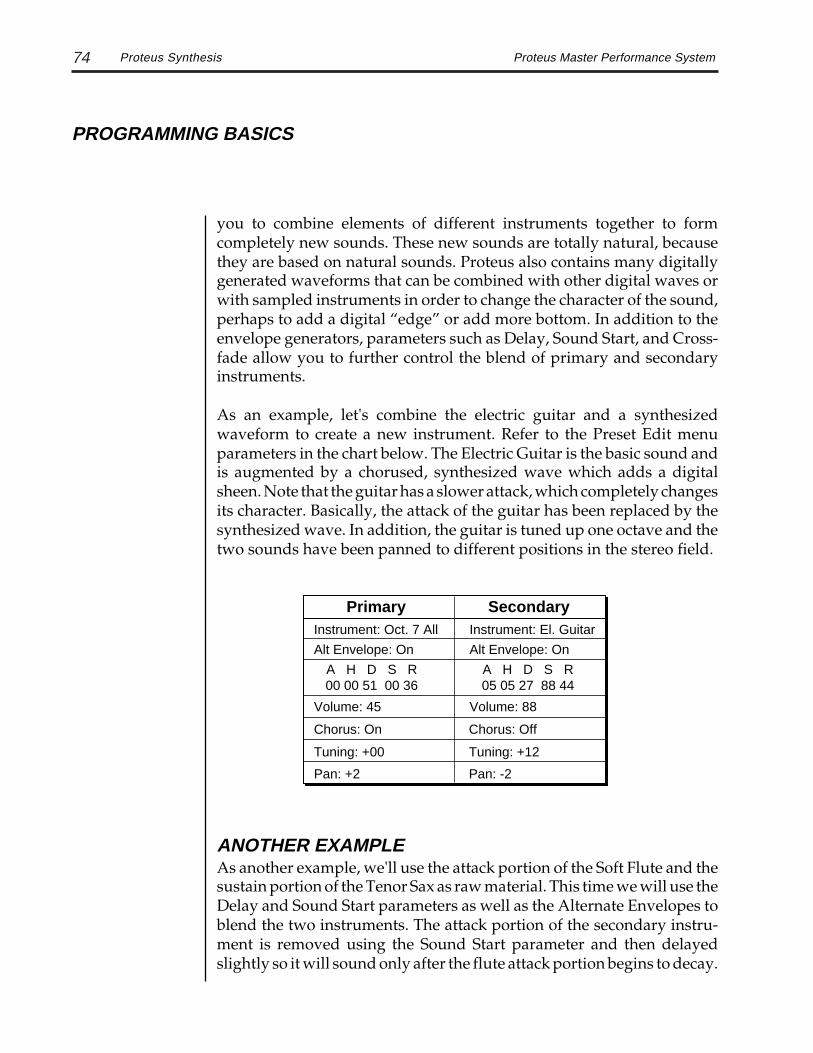
74 Proteus Master Performance System
PROGRAMMING BASICS
you to combine elements of different instruments together to formcompletely new sounds. These new sounds are totally natural, becausethey are based on natural sounds. Proteus also contains many digitallygenerated waveforms that can be combined with other digital waves orwith sampled instruments in order to change the character of the sound,perhaps to add a digital “edge” or add more bottom. In addition to theenvelope generators, parameters such as Delay, Sound Start, and Cross-fade allow you to further control the blend of primary and secondaryinstruments.
As an example, let's combine the electric guitar and a synthesizedwaveform to create a new instrument. Refer to the Preset Edit menuparameters in the chart below. The Electric Guitar is the basic sound andis augmented by a chorused, synthesized wave which adds a digitalsheen. Note that the guitar has a slower attack, which completely changesits character. Basically, the attack of the guitar has been replaced by thesynthesized wave. In addition, the guitar is tuned up one octave and thetwo sounds have been panned to different positions in the stereo field.
Proteus Synthesis
ANOTHER EXAMPLEAs another example, we'll use the attack portion of the Soft Flute and thesustain portion of the Tenor Sax as raw material. This time we will use theDelay and Sound Start parameters as well as the Alternate Envelopes toblend the two instruments. The attack portion of the secondary instru-ment is removed using the Sound Start parameter and then delayedslightly so it will sound only after the flute attack portion begins to decay.
Primary Secondary
Volume: 45
Chorus: On
Pan: +2
Instrument: El. Guitar
A H D S R05 05 27 88 44
Pan: -2
Tuning: +12Tuning: +00
Volume: 88
Chorus: Off
Instrument: Oct. 7 All
Alt Envelope: On Alt Envelope: On
A H D S R00 00 51 00 36

75Proteus Master Performance System
PROGRAMMING BASICS
Sequencing
The alternate envelopes are used to “fine tune” the splice. Furthermore,the flute attack has been detuned a bit sharp so the composite sound willstart sharp and fall into correct pitch. Continue your experiments usingthis example, but changing the primary and secondary instruments.When you have found a good combination, fine tune the delay, samplestart, volume and envelope parameters. Feel free to play with the modu-lation parameters as well.
Primary Secondary
Volume: 109
Fine Tuning: +05
Delay: 000
Instrument: Tenor Sax
A H D S R06 00 38 85 40
Delay: 002
Tuning: +12Tuning: +12
Volume: 83
Fine Tuning: +00
Instrument: Soft Flute
Alt Envelope: On Alt Envelope: On
A H D S R04 02 16 00 16
Sound Start: 000 Sound Start: 040
USING PROTEUS WITH A SEQUENCERThe Proteus was designed from its conception with multi-timbral se-quencing in mind. Just take a look at the main screen (or the 14th screenin the Performance Edit menu). Each Performance Map can store adifferent multi-mode setup for all 16 MIDI channels.
C01 Vol127 Pan+P000 Grand Piano
In order to respond to multiple MIDI channels, Proteus must be inMulti-Mode.
Multi-Mode is enabled by pressing the Multi button on the front panel.When the Multi LED is lit, Proteus will respond to multiple MIDIchannels.
The main screenand the 14th screen inthe Performance Editmenu are identical.

76 Proteus Master Performance System
PROGRAMMING BASICS
Using the 32 Channels
The preset for each MIDI channel is selected from this screen. Press thecursor button to move the cursor up so that it is underneath the channelnumber.
C01 Vol127 Pan+P000 Grand Piano
Turn the data entry control and you will see that every MIDI channel hasa preset assigned to it. Just select a preset for each of the MIDI channels.It’s simple! (The multi-mode selection screen is also available in thesecond screen of the Performance Edit menu.) If you wish to reservecertain channels for other MIDI synthesizers, set the preset to “099-default”. Volume and Pan position can also be adjusted for each channel.
USING THE 32 CHANNELSThe Proteus has 32 independent audio channels which are utilizeddynamically. With 32 channels and 300 presets, you have a universe ofsonic textures at your disposal. Some Proteus presets utilize linkedpresets or use the double+detune function to make them sound fatter.While this is fine when the preset is played solo, you may begin to run outof channels when Proteus is played multi-timbrally. Linking and dou-bling cause twice as many channels to be used by the preset. Learn to“budget” your output channels for maximum efficiency.
CHANNEL RIPOFFWhen Proteus uses up all its 32 channels and needs more, it steals achannel from the key that has been held the longest. This is commonlyknown as channel ripoff. You will most commonly encounter this ripoffwhen using Proteus in multi-timbral mode. Since the Proteus dynami-cally allocates channels as needed, to eliminate ripoff you must either,play fewer notes, use simpler sounds, or turn off doubling (pri/sec, orlinked presets).
The following ROMpresets use only oneoutput channel:
007 Sweet n' Saxy011 Metal Cables013 Acoustic Guitar024 Solo Trumpet027 Latin Drums028 Latin Perc.044 Solo Trombone053 Underground065 Rock Drums098 Machine Snare

77Proteus Master Performance System
PROGRAMMING BASICS
Instrument Definition
INSTRUMENT DEFINITIONIf your sequence has a instrumental section using numerous chords, itmay be advantageous to use a basic preset without links or doubling. Apreset will sound much different alone than when combined with anensemble. Try to resist the temptation to make every sound as fat aspossible or you can wind up with “MIDI Soup”; a huge, stifling soundwith every possible audio frequency filled. Each voice in your composi-tion should have it’s own identity. Save the monster sounds for solos ordramatic effects.
PRE-SEQUENCE SETUPOne way to keep everything neat and tidy is to centralize everything at thesequencer (patch changes, continuous controllers, etc.). This is especiallyeasy if you have a “full-featured” sequencer which allows you to store andedit continuous controller messages. The advantage of storing everythingin the sequence is that all the data will be in one place and changing aperformance map in the Proteus won't cause the sequence you wrote twoweeks ago to play the wrong presets or effects.
The basic idea of a pre-sequence setup is to send out MIDI information justbefore the start of the song. This MIDI information will select all theproper presets, adjust the mix and pan positions of each preset.
Note: Proteus setup information should be transmitted from the se-quencer before the song actually starts, perhaps during a lead-in measureor countdown. DO NOT send setup information just before the first beatof the song or MIDI timing errors could result.
USING EFFECTS IN MULTI MODEIt would be nice if there was a separate effect for each MIDI channel.Unfortunately, there isn't! There are only two effect processors so youhave to “budget” them in your multi-timbral sequence. Effects can bechanged during a sequence either by selecting a new performance map orby using the realtime MIDI control numbers shown on pages 140 and 141.To avoid nasty pops and glitches, sound must not be playing through theeffect while it is being changed.
REMEMBER…In Multimode, the effects settings in the Performance Map are used.

78 Proteus Master Performance System
PROGRAMMING BASICS
Realtime Effects Control
REALTIME EFFECTS CONTROLSpecial continuous controller messages can be set up to control the effectsparameters as shown in the Performer™ sequencer screen below.
In the Performer screen above, the Proteus effect parameters have all beenprogrammed and named so that they can be adjusted during the se-quence. Labelling everything helps to reduce the confusion factor. Onecaution however. The effects parameters have not been “de-zippered”,meaning that there may be slight glitches in the sound if an effect is beingused while its parameters are being changed. The MIDI continuouscontroller numbers for all the effect parameters are listed on pages 140and 141 of this manual.
MIDI BANK SELECTAnother function you may want to access over MIDI is preset bank select.To change Proteus preset banks send:
1) Controller 0 Value 00
2) Controller 32 Value 00 = ROM, Value 01 = RAM, Value 02 = Card
3) Send Program Change (Program Change MUST be sent to change bank.)

79Proteus Master Performance System
PROGRAMMING BASICS
Pri ATTACK
Pri HOLD
Pri DECAY
Pri SUSTAIN
Pri RELEASE
Sec ATTACK
Sec HOLD
Sec DECAY
Sec SUSTAIN
Sec RELEASE
XFADE DIRECTION
XFADE MODE FD Xsw
XFADE BALANCE
XFADE AMOUNT
SWITCH POINT
LFO 1 SHAPE
LFO 1 AMOUNT
LFO 1 RATE
LFO 1 DELAY
LFO 1 VARIATION
LFO 2 SHAPE
LFO 2 AMOUNT
LFO 2 RATE
LFO 2 DELAY
LFO 2 VARIATION
AUX ENV AMOUNT
AUX ENV DELAY
AUX ENV-ATTACK
AUX ENV-HOLD
AUX ENV-DECAY
AUX ENV-RELEASE
AUX ENV-SUSTAIN
Sec VOLUME
Pri PAN
Pri COARSE TUNE
Sec COARSE TUNE
Pri DOUBLE+DELAY
Pri DELAY
Sec DELAY
Pri SOLO
Pri SOUND START
Sec SOUND START
Pri INSTRUMENT
Sec INSTRUMENT
KEY RANGE
Pri KEY RANGE
Sec KEY RANGE
Pri VOLUME
Sec PAN
Pri FINE TUNE
Sec FINE TUNE
Sec DOUBLE+DELAY
Sec SOLO
Pri EFFECT ASSIGN
Sec EFFECT ASSIGN
A EX AMOUNT
B FX AMOUNT
B->A FX AMOUNT
Pri REVERSE
Sec REVERSE
Pri ALT. ENVELOPE
Sec ALT. ENVELOPE
1 -
3 -
2 -
LINK 1
LINK 2
LINK 3
KYBD TUNING
VEL. CURVE
KYBD CENTER
CONTROLLER D
PRESSURE AMT.
4 -
6 -
5 -
7 -
8 -
CONTROLLER MOD
CONTROLLER B
CONTROLLER C
3
2
LOCAL
FOOTSWITCH CONTROL
CONTROLLER AMOUNT
REALTIME MOD. CONTROL
1 >
2 >
3 >
4 >
5 >
6 >
KEY/VELOCITY CONTROL
P-BEND RANGE
This patch sheet can be photocopied and used to keep written records of your favorite Proteus sounds.
Patch Sheet
PROTEUS Patch Sheetpart 1

80 Proteus Master Performance System
PROGRAMMING BASICS
Patch Sheet
PROTEUS Patch Sheetpart 2
FREQUENCY 1
BANDWIDTH 1
BOOST/CUT 1
FREQUENCY 2
BANDWIDTH 2
STEREO EQ A
BOOST/CUT 2
REVERB TYPE
DECAY TIME
REVERB EFFECTS LFO RATE
LFO DEPTH
MIN DELAY
FEEDBACK
MIX
CHORUS"A" EFFECTS
LFO RATE
LFO DEPTH
MIN DELAY
FEEDBACK
PHASER FLANGERR DELAY TIME
R TAP LEVEL
L DELAY TIME
L TAP LEVEL
FEEDBACK
DELAY X-DELAY ECHO
R DELAY TIME
R TAP LEVEL
L DELAY TIME
L TAP LEVEL
FEEDBACK
DELAY X-DELAY
LFO RATE
LFO DEPTH
MIN DELAY
FEEDBACK
MIX
CHORUS
LFO RATE
LFO DEPTH
MIN DELAY
FEEDBACK
PHASER FLANGER
INPUT FILTER
OUTPUT LEVEL
FUZZ 1 FUZZ LITE
OUTPUT FILTER
"B" EFFECTS
FREQUENCY L
BANDWIDTH L
BOOST/CUT L
FREQUENCY R
BANDWIDTH R
STEREO EQ B
BOOST/CUT R
RING MODULATOR

PRESET EDIT MENU
81Proteus Master Performance System
PRESET EDIT MENU
Edit Menu

PRESET EDIT MENU
82 Proteus Master Performance System

PRESET EDIT MENU
83Proteus Master Performance System
The preset edit menu contains functions that can be modified by the userand then saved as preset information in one of the user presets. Forexample, the LFO speed or other parameter can be edited, then the presetcan be saved to a user location (100-199 Internal RAM, 200-299 RAMCard).
TO ENABLE THE PRESET EDIT MENUPress the Preset Edit key, lighting the LED. The current screen will be theone most recently selected since powering up the machine. The cursorwill appear underneath the first character of the screen heading on lineone.
TO SELECT A NEW SCREENPress the left or right cursor key repeatedly until the cursor is underneaththe screen heading (or press Enter ). Rotate the data entry control or usethe increment/decrement keys to select the screen.
TO MODIFY A PARAMETERPress the left or right cursor key repeatedly until the cursor is underneaththe desired parameter. Rotate the data entry control, use the increment/decrement keys or use the numeric keys to change the parameter.
TO SAVE A PRESET While in the Preset Edit menu, press the Save/Copy button. Use the dataentry knob or the increment/decrement buttons to select the new presetlocation. Press Enter to store the preset.
TO RETURN TO PRESET SELECT MODE Press the Preset Edit button, turning off the LED.
Preset Editing
PRESET EDIT MENU
Warning: If you se-lect another preset orturn off power, changesmade in the Preset Editmenu will be lost unlessthe preset is saved us-ing the Save/Copyfunction .
While the Preset Editmenu is activated,incoming MIDI presetchanges are ignored.This is a quick and easyway to temporarily turnMIDI Preset ChangeOFF.

PRESET EDIT MENU
84 Proteus Master Performance System
46
9;
=@
B
EG
IL
N
QS
UX
Z
]_
ad
f
ik
mp
r
uw
y|->
-/
1(
*
!#
%
02
3
57
8
:<
>
?A
C
DF
H
JK
M
OP
R
TV
W
Y[
¥
^`
b
ce
g
hj
l
no
q
st
v
xz
<-
+,
.
&'
)
blank
"$
C3C2 C4 C5 C6C1C0C-1
C C# D D# E F F# G G# A A# B Pitch
OctaveNo.
-1
0
1
2
3
4
5
6
"! # $ % &blank
' ( ) * + , - . / 0 1 2
3 4 5 6 7 8 9 : ; < >=
? @ A B C D E F G H I J
K L M N O P Q R S T U V
W X Y Z [ ¥ ] ^ _ ` a b
c d e f g h i j k l m n
o p q r s t u v w x y z
|
-2
Preset Edit Functions
PRESET EDIT FUNCTIONS
PRESET NAMEPreset Name allows you to name each of the user presets with a name ofup to 12 characters. Position the cursor under the character location anduse the data entry control to change the character. The keyboard can alsobe used to select characters. The charts below show the keyboardcharacter assignment.
PRESET NAME000 Untitled

PRESET EDIT MENU
85Proteus Master Performance System Primary Instrument
PRIMARY INSTRUMENTThis function allows you to select which of the available instrumentsounds (or none) will be placed on the primary layer of the current userpreset.
INSTRUMENT priI002 Piano Pad
SECONDARY INSTRUMENTThis function allows you to select which of the available instrumentsounds (or none) will be placed on the secondary layer of the current userpreset.
INSTRUMENT secI001 Piano
PRESET KEY RANGEKey range sets the maximum keyboard range of both primary andsecondary instruments. This sets the keyboard range for the entire presetand will further limit the primary and secondary keyboard ranges. Thekey range can be set anywhere from C-2 to G8.
KEY RANGEC-2 -> G8
C-2 C-1 C0 C1 C2 C3 C4 C5 C6 C7 C8
= Proteus 5 Octave Keyboard Range
MIDI Keyboard RangeMIDIKey #
KeyName
0 12 24 36 48 60 72 84 96 108 120 127
Simply changingthe instrumentcreates an entirelynew sound whileretaining all otherparameters of thepreset.
Any value that is akey number can beset by playing thedesired key.

PRESET EDIT MENU
86 Proteus Master Performance SystemPrimary and Secondary Key Range
PRIMARY KEY RANGEThis sets the keyboard range of the primary instrument. This is useful forcreating positional crossfades and keyboard splits between the primaryand secondary layers. The key range can be set anywhere from C-2 to G8.
KEY RANGE priC-2 -> G8
SECONDARY KEY RANGEThis sets the keyboard range of the secondary instrument. The key rangecan be set anywhere from C-2 to G8.
KEY RANGE secC-2 -> G8
Primary InstrumentKey Range
Key RangeSecondary Instrument
This diagram shows how a "split" keyboard can be programmed using the primaryand secondary instruments.
Pri Instr.
Sec Instr.
Key Range
This diagram shows how instruments can be layered or "stacked" using the primaryand secondary instruments.
Preset Key Rangewill further limit both theprimary and secondaryinstruments.

PRESET EDIT MENU
87Proteus Master Performance System Volume
VOLUMEVolume sets the amplitude of the primary and secondary instruments.This function also allows you to compensate for the relative volumedifferences between instruments.
VOLUMEpri:127 sec:64
PANPan allows you to independently set the initial pan position of the primaryand secondary instruments. A value of -7 pans the instrument hard leftand a value of +7 pans the instrument hard right. This pan setting is onlyvalid if “P”, for preset pan, is selected in the main display.
PANpri:-7 sec:+7
COARSE TUNINGThis function allows you to change the tuning of the primary andsecondary instruments in semitone intervals. The coarse tuning range is-36 to +36 semitones. A coarse tuning setting of "00" would indicate thatthe instrument is tuned to concert pitch (A=440 Hz).
TUNING coarsepri:+00 sec:+00
FINE TUNINGThis function allows you to change the tuning of the primary andsecondary instruments in 1/64 semitone intervals (approx. 1.56 cents).The fine tuning range is ± 1 semitone.
TUNING finepri:+00 sec:+00
There are threevolume controls on theProteus.
1. Front Panel Volume2. Channel Volume3. Instrument Volume

PRESET EDIT MENU
88 Proteus Master Performance System
DOUBLE + DETUNEDouble + Detune thickens the sound by doubling the sound and thendetuning it. This screen allows you select the amount from a range of 1 to15 or turn the effect Off. When on, the number of output channels used byan instrument will be doubled.
DOUBLE + DETUNEpri:Off sec:07
DELAYDelay varies the time between when a MIDI Note On message is receivedand the onset of a note. The delay time is adjustable from 0 to 13 seconds(000-127).
DELAYpri:000 sec:000
SOLO MODESolo mode switches an instrument into monophonic (no chords) mode. Ifa new note is played while another is being held, the pitch will change butthe envelope generator will not restart the attack.This allows a legato orslurred playing style. Solo mode works well with guitar and windcontrollers.
SOLO MODEpri:Off sec:On
SOUND STARTThis sets the point along its length where a sound begins playing whenyou hit a key. A setting of 000 plays a sound from the beginning, highervalues move the sample start point toward the end of the sound.
SOUND STARTpri:000 sec:000
Double + Detune

PRESET EDIT MENU
89Proteus Master Performance System Effects
L
R
L
R
EFFECTA
Amount
EFFECTB
Amount
Pan
L
R
Pan
L
R
PriDCA
SecDCA
SubmixOutputs
MainOutputs
OutputBuss
BA
B
A
Dry
Sub.Outputs
Block diagram of the Proteus effects section. The effect pathways are stereo.
EFFECTSThis function allows you to select one of the two available effects bussesfor each instrument, have the instrument remain dry (no effects) or toroute the instrument to the submix outputs. The type of effects used andtheir amounts are selected in the next two screens.
EFFECTSpri:Dry sec:A
EFFECT AThis function allows you to select which effect is assigned to effect buss A.The A effects consist of several types of stereo reverb, two kinds of stereodelay, stereo flanger, stereo chorus, stereo echo and stereo phaser.
FXA:Hall 2Decay Time: 200

PRESET EDIT MENU
90 Proteus Master Performance SystemEffects
EFFECT BThis function allows you to select which effect is assigned to effect bussB. The B effects include: stereo flanger, stereo chorus, stereo digital delay,stereo fuzz and ring modulator.
FXB:StereoFlangeLFO Rate 050
EFFECTS AMOUNTThis function allows you to adjust the percentage of wet and dry signals(processed and unprocessed) with 100% being only processed signal.Additionally, the B->A parameter allows you to adjust the amount of theB effect which is fed through the A effect device. If B>A is set one valueabove 100%, “Only” is displayed and the B amount changes to Off. Thisdisconnects effect B from the main outputs and routes all of the effect Bsignal through effect A.
FX AMOUNT A:40%B>A:0% B:82%
FOR DETAILED EXPLANATIONS OF EACH EFFECT,SEE THE EFFECTS CHAPTER IN THIS MANUAL.
REVERSE SOUNDWhen reverse sound is turned On, the instrument sample will be playedbackwards. When an instrument is reversed, any loops in the sound willbe ignored, which means that the sound will not sustain indefinitely.
REVERSE SOUNDpri:Off sec:On

PRESET EDIT MENU
91Proteus Master Performance System Reverse Sound
ALTERNATE ENVELOPE ON/OFFEach instrument has its own factory preset AHDSR volume envelopewhich is normally employed. Turn the alternate envelope On if you wishto alter the factory preset volume envelope.
ALT ENVELOPEpri:Off sec:On
PRIMARY and SECONDARY ALTERNATE ENVELOPEThis function allows you to adjust the alternate volume envelope parame-ters for the primary and secondary instruments. The parameters areAttack time, Hold time, Decay time, Sustain level, Release time and areadjustable from 00 to 99.
P: A H D S R 00 00 00 99 16
S: A H D S R00 00 00 99 16
DCA
Atk Dec Rel
NormalEnvelope
Atk Dec Rel
AlternateEnvelope
See page 139 forthe envelope timecharts.

PRESET EDIT MENU
92 Proteus Master Performance SystemCrossfade Mode
By overlapping the primary and secondary instruments, you can crossfade or cross-switchbetween the two layers.
PrimaryInstrument
Key Range
Key Range
SecondaryInstrument
Crossfade Range
CROSSFADE MODECrossfade is the relative loudness of the primary and secondary instru-ments. Crossfade mode selects how the relative loudness is controlled.
Off: When Off is selected, none of the crossfade parameters will haveany effect and both instruments will be fully On.
Crossfade: When crossfade is selected, a control input is used to fadebetween the primary and secondary. Any modulation source may beused as an input (velocity, wheel, etc.) The modulation source is pro-grammed in the key/velocity or realtime modulation screens.
Cross-switch: When cross-switch mode is selected, you get only onelayer at a time. The other layer is selected if the key position or velocitycrosses a certain threshold or if a footswitch controlling cross-switch isactivated. The switch occurs only at the start of the note; no furtherswitching takes place while the key is held down. If key position orvelocity is routed to cross-switch, the threshold is the switch point. Toenable the Cross-switch function, you must assign Crossfade to amodulation source in the Realtime or Velocity Modulation screen.Realtime controllers do not have any effect when routed to cross-switch.
XFADE MODEOff
For more information,see Cross-Switch Pointon page 94.
To use the keyboardfor crossfade, set thebalance to 64 and keycenter to the split point.

PRESET EDIT MENU
93Proteus Master Performance System
CROSSFADE DIRECTIONThis function determines the polarity of the crossfade or cross-switch.The direction is either primary secondary, or secondary primary.The primary instrument is louder when the control source is below thecrossfade balance point.
XFADE DIRECTIONPri -> Sec
CROSSFADE BALANCEThe crossfade balance parameter determines the initial balance betweenthe primary and secondary layers. Higher values shift the volume to thesecondary instrument. Modulation subtracts from the primary volumeand adds to the secondary volume. When crossfade modulation andbalance equal 64, the two instruments are equal.
XFADE BALANCE064
Crossfade Direction
Pri Sec Large Crossfade Amount
Pri Sec Medium Crossfade Amount
Pri Sec Small Crossfade Amount
0 255
0 255
0 255
Balance + Mod
Balance + Mod
Balance + Mod
Modulation and Crossfade Balance are added together to determine the mixture of primaryand secondary instruments. Higher values increase the secondary volume.
A Crossfade Balancesetting of 000 would beappropriate with asource such as a modu-lation wheel orfootpedal which onlychange the value in apositive direction.
Crossfade must beassigned to a modula-tion source in theRealtime or Velocitymodulation screens.

PRESET EDIT MENU
94 Proteus Master Performance System
CROSSFADE AMOUNTThe crossfade amount parameter determines the range over whichcrossfading will occur. Crossfade amount is variable from 000 to 255. Thelarger the value, the more modulation will be required to effect a completecrossfade.
XFADE AMOUNT128
CROSS-SWITCH POINTThe cross-switch point parameter determines the point at which cross-switching will occur when key position or velocity is controlling cross-switch.
SWITCH POINT064 c#2
LFO 1 - SHAPE and AMOUNTThis screen controls the waveshape and amount of Low FrequencyOscillator 1. The LFO can be used to produce vibrato (when routed topitch), or tremolo (when routed to volume). The five LFO waveshapesare: Triangle, Sine, Square, Sawtooth, and Random. The amount can bevaried from -128 to +127. Negative values will produce inverted wave-shapes.
LFO1 SHAPE AMT Rand +127
Triangle
Square
Sine
Sawtooth
Random
Crossfade Amount
KeyVelocity
To enable the Cross-switch function, youmust assign Cross-fade to a modulationsource in the Realtimeor Velocity Modulationscreen.

PRESET EDIT MENU
95Proteus Master Performance System
LFO 1 - RATE, DELAY and VARIATIONThis screen controls the rate, delay and variation of LFO 1.
LFO Rate: varies the LFO speed from 0.052 Hz to 25 Hz (000-127).
LFO Delay: sets the amount of time between hitting a key and the onsetof modulation. This can be used to simulate an effect often used byacoustic instrument players, where the vibrato is brought in only after theinitial note pitch has been established. The delay range is variable from 0to 13 seconds (000-127).
LFO Variation: sets the amount of random variation of an LFO eachtime a key is pressed. This function is useful for ensemble effects, whereeach note played has a slightly different modulation rate. The higher thenumber, the greater the note to note variation in LFO rate. LFO variationis variable from 000-127.
LFO1 RT DLY VAR 000 000 000
LFO 2 - SHAPE and AMOUNTLFO 2 is functionally identical to LFO 1.
LFO 2 - RATE, DELAY and VARIATIONLFO 2 is functionally identical to LFO 1.
time
keydown
Delay
The LFO wave begins after the specified delay time has elapsed.
LFO 1

PRESET EDIT MENU
96 Proteus Master Performance SystemAuxiliary Envelope
This diagram shows the six stages of the Auxiliary Envelope Generator.
Delay
level
time
keydown
Attack
Hold
Decay
Sustain
Release
keyreleased
AUXILIARY ENVELOPEThis is a supplementary, utility envelope that can be routed to anyrealtime control destination. The auxiliary envelope parameters are:Envelope Amount, Delay, Attack Time, Hold Time, Decay Time, SustainLevel, and Release Time. The delay time is variable from 0 to 13 seconds(000-127). The envelope amount is variable from -128 to +127. Negativevalues will produce inverted envelopes.
AUX ENV AMT DLY +127 000
A: A H D S R 00 00 00 99 20

PRESET EDIT MENU
97Proteus Master Performance System KYBD/ Velocity Modulation
KEY/VELOCITY CTL1 V>Attack -064
ModulationSource
ModulationDestination
ModulationAmount
PatchNumber
AuxiliaryDAHDSR
AmtAtk Dec Rel
LFO 1
Amount Freq.
LFO 2
Amount Freq.
Modulation Destinations
Pan
R
L
R
L
Level
Level
VolumeAHDSR
Atk Dec Rel
DCA
DCA Pan
Atk Dec Rel
VolumeAHDSR
X-Fade
PrimaryInstrument
PitchSample
Start
Tone
SecondaryInstrument
PitchSample
Start
Tone
VELOCITY
VELOCITYCURVE
KEY NUMBER
KEYBOARDCENTER
Keyboard and Velocity Modulation Sources
EFFECT
EFFECT
Modulation Sources:Key Number and KeyVelocity
Destinations: Off,Pitch, Primary Pitch,Secondary Pitch,Volume, PrimaryVolume, SecondaryVolume, Attack,Primary Attack,Secondary Attack,Decay, PrimaryDecay, SecondaryDecay, Release,Primary Release,Secondary Release,Crossfade, LFO 1Amount, LFO 1 Rate,LFO 2 Amount, LFO 2Rate, AuxiliaryEnvelope Amount,Auxiliary EnvelopeAttack, AuxiliaryEnvelope Decay,Auxiliary EnvelopeRelease, SampleStart, Primary SampleStart, SecondarySample Start, Pan,Primary Pan,Secondary Pan, Tone,Primary Tone,Secondary Tone
When ModulatingEnvelope Attack,Decay, or ReleaseTimes:
Positive amounts ofmodulation increasethe time.
Negative amounts ofmodulation decreasethe time.
KEYBOARD and VELOCITY MODULATION CONTROLThese functions allow you to route keyboard and velocity information toany of the modulation destinations on the Proteus. Up to 6 simultaneouspaths or patches may be programmed. For each modulation patch, thereis a source (keyboard or velocity), and a corresponding amount param-eter which is variable from -128 to +127. Place the cursor under theappropriate parameter and change the patch number, modulationsource, modulation destination, or the amount using the data entrycontrol. If a parameter is not labeled either primary or secondary, itaffects both.

PRESET EDIT MENU
98 Proteus Master Performance System
REALTIME CTL1 LFO1 ->Pitch
ModulationSource
ModulationDestination
PatchNumber
LFO 1
Amount Freq.
LFO 2
Amount Freq.
AuxiliaryDAHDSR
AmtAtk Dec Rel
Pan
R
L
R
L
Level
Level
VolumeAHDSR
Atk Dec Rel
DCA
DCA Pan
Atk Dec Rel
VolumeAHDSR
Realtime Modulation Sources
X-Fade
PrimaryInstrument
Pitch
Modulation Destinations
LFO 2AUXILIARYENVELOPELFO 1
MIDICONTROLLER
Mod/B/C/D
POLYPRESSURE
MONOPRESSUREPITCH WHEEL
SecondaryInstrument
Pitch
EFFECT
EFFECT
REALTIME MODULATION CONTROLThese functions allow you to route realtime controllers to any of themodulation destinations on Proteus except Tone, Sample Start and Pan.Up to 8 simultaneous patches may be programmed. For each modulationpatch, there is a source and a destination parameter. Place the cursorunder the appropriate parameter and change the patch number, modu-lation source or modulation destination using the data entry control. Ifa parameter is not labeled either primary or secondary, it affects both.
Realtime Modulation
Modulation Sources:Pitch Wheel, MIDIControl A, MIDIControl B, MIDIControl C, MIDIControl D, MonoPressure, PolyphonicPressure, LFO 1, LFO2, Auxiliary Envelope
Destinations: Off,Pitch, Primary Pitch,Secondary Pitch,Volume, PrimaryVolume, SecondaryVolume, Attack,Primary Attack,Secondary Attack,Decay, PrimaryDecay, SecondaryDecay, Release,Primary Release,Secondary Release,Crossfade, LFO 1Amount, LFO 1 Rate,LFO 2 Amount, LFO 2Rate, AuxiliaryEnvelope Amount,Auxiliary EnvelopeAttack, AuxiliaryEnvelope Decay,Auxiliary EnvelopeRelease

PRESET EDIT MENU
99Proteus Master Performance System
FOOTSWITCH CONTROLThis function allows you route the 3 footswitch controllers (Local, 2 or 3)to any of the footswitch destinations. Local refers to the footswitch jack onthe rear panel. Footswitches 2 and 3 are MIDI footswitches. (See MIDIFootswitch Assign in the Master Edit menu.) The footswitches can berouted to switch: Sustain (pri/sec/both), alternate volume envelope(pri/sec/both), alternate volume release (pri/sec/both), or cross-switchbetween the primary and secondary instruments.
FOOTSWITCH CTLLocal-> Sustain
MIDI CONTROLLER AMOUNTThis function allows you to specify an amount parameter (variable from-128 to +127) for each of the modulation controllers. MOD refers to theProteus modulation wheel. Controllers B, C and D are MIDI controllersas assigned in the Master Edit menu. The Control Pedal jack on the rearpanel can be assigned to Controller B. (See MIDI Controller Assign in theMaster menu.)
CONTROLLER AMTMOD:+32 B:-090
CONTROLLER AMTC:-64 D:-090
PRESSURE AMOUNTThis function allows you to specify an amount parameter for mono orpoly keyboard pressure data. The pressure amount is variable from -128to +127.
PRESSURE AMOUNT+127
Footswitch Control

PRESET EDIT MENU
100 Proteus Master Performance SystemPitch Bend Range
PITCH BEND RANGEThis function allows you to specify the pitch wheel range for the currentpreset or it can be set to be controlled globally (set in the Master menu).Pitch bend range is only applied when the pitch wheel is used to controlpitch.
PITCH BEND RANGE+- 12 semitones
VELOCITY CURVEKeyboard velocity data can be modified by a velocity curve in order toprovide different types of dynamics in response to your playing or betteradapt to the MIDI controller. This function allows you to select one of thefour velocity curves or leave the velocity data unaltered (off). In addition,the velocity curve can be set to "Global", which means that the globalvelocity curve (programmed in the Master menu) is used.
VELOCITY CURVEGlobal
0
20
40
60
80
100
120
0 20 40 60 80 100
Played Velocity120
Res
ult
Vel
oci
ty
0
20
40
60
80
100
120
0 20 40 60 80 100
Played Velocity120
Res
ult
Vel
oci
ty
Curve 3 Curve 4
Curve 1 Curve 2
0
20
40
60
80
100
120
0 20 40 60 80 100
Played Velocity120
Res
ult
Vel
oci
ty
0
20
40
60
80
100
120
0 20 40 60 80 100
Played Velocity120
Res
ult
Vel
oci
ty

PRESET EDIT MENU
101Proteus Master Performance System Keyboard Center
KEYBOARD TUNINGIn addition to the standard equally divided octave tuning, Proteuscontains three other types of scale tuning and one user-definable tuning.This function selects which tuning will be used in the current preset.The choices of keyboard tunings are:
Equal tuning (12 tone equal temperament)Standard Western tuningJust C tuning (just intonation)Based on small interval ratios; sweet and pure; non-beating intervalsVallotti tuning (Vallotti and Young non-equal temperament)Similar to 12 tone equal temperament; for a given scale, each key has adifferent character19 Tone tuning (19 tone equal temperament)19 notes per octave; difficult to play but works well with a sequencerGamelan (Javanese) tuning (5 tone Slendro and 7 tone Pelog)Pelog-white keys; Slendro-black keys; exotic tunings of Gamelan flavorUser tuning (1-4) which is defined in the Master menu.
KEY CENTER
+
-
0
-
+
KEYBOARD CENTERThe Keyboard Center parameter establishes a reference point for key-board modulation. Keys above this point will have a positive value andkeys below it will be negative. The keyboard center can be set to any keywithin the range C-2 to G8.
KEYBOARD CENTERc#3

PRESET EDIT MENU
102 Proteus Master Performance SystemPreset Links
PRESET #1
PRESET #2Key Range
Key Range
LINK
CREATING A SPLIT KEYBOARD
Split or Layeredkeyboards canalso be created inthe Quick Keysection of thePerformance Editmenu.
PRESET #1
PRESET #2
LINK
LAYERING TWO PRESETS
Key Range
PRESET LINKSPresets may be linked to other presets in order to create layering orkeyboard splits as part of the preset instead of a performance map. Thecurrent preset can be linked with up to three other presets. Each linkedpreset can be assigned to a specific range in order to easily create keyboardsplits. The modulation parameters specified in each preset remain ineffect for each preset in the link. Beginning with the lowest numberedlinks, presets will retain their programmed effect assignments until thetwo effect processors have been used up. All other linked presets willretain their effect buss routings only. See page 106 for more information.
LINK 1 c#1->f#4000 Preset Name
LINK 2 c#1->f#4191 Preset Name
LINK 3Off

103Proteus Master Performance System
EFFECT PROGRAMMING
Effects
EFFECT PROGRAMMING

104 Proteus Master Performance System
EFFECT PROGRAMMING

105Proteus Master Performance System
EFFECT PROGRAMMING
Effect Routing Modes
BACKGROUND: EFFECT ROUTING MODESThe Proteus Master Performance System contains two separate effectsprocessors which may be applied to the final sound. The effect processorscan be a part of the individual preset when single presets are being used,or they can be connected via an effects buss system when multiple presetsare in use. The main point is that there are two and only two effectprocessors.
Single Preset ModeWhen using single presets, it is desirable to have the type of effect linkedwith the preset. Proteus goes a little further by allowing you to assign aseparate effect to the primary and secondary instruments.
Multiple Preset ModeWhen using multi-mode, where up to 16 presets can be accessed at once,the effect buss (A, B or None) may be programmed as part of the Presetor a Performance Map, but the type of effects and their amounts arealways programmed in the Performance Edit menu. The effects selectedin the preset are ignored. These two assignment schemes give you the bestof both worlds whether you are playing single or multiple presets.
Effect AReverb
Effect BFlanging
Performance Edit
Channel 1A
Channel 2B
Channel 3Dry
Channel 4Sub 1
Channel 16Preset
FX AmountsA:80% B:50% B->A:0%
MIDI
R
LPreset onMIDI
Channel 01
R
LPreset on
MIDIChannel 16
Pri - ASec - B
Preset Edit
R
LPreset onMIDI
Channel 04
R
LPreset onMIDI
Channel 02
SUB 1
MAIN
MAIN
MAIN
Reverb
Flanging
Pri- ReverbSec-Flange
EFFECT PROGRAMMING
PRESET
PRIMARY
SECONDARY EFFECT(Flanging)
R
LEFFECT(Reverb)
Single PresetEffect programmedin the Preset isused.
Multiple PresetsEffect programmedin the PerformanceMap is used.

106 Proteus Master Performance System
EFFECT PROGRAMMING
SPLIT KEYBOARD EFFECTSA special case arises when the Proteus keyboard is split using a Quick Keyprogram (see the Performance Edit menu). There are only two effectprocessors, but up to eight possible assignments. Effects are still assignedaccording to the preset assignment as long as no more than two effects areused. If more than two effects are used (see diagram below), the effectswill be assigned normally beginning with Zone 1 (then Zone 2, 3, 4). Whenthe two effects are used up, the remaining zones will follow the preseteffect buss routing (A, B, Dry, or Sub), but the type of effect will bedetermined by the first two effects used.
Split Keyboard Effects
Preset 22
Zone 1
Pri - A - Reverb
Sec - B - Dry
Preset 01
Zone 2
Pri - A - Delay
Sec - A - Delay
Preset 199
Zone 3
Pri - A - Phaser
Sec - B - Reverb
Preset 46
Zone 4
Pri - B - Ring Mod
Sec - A - Echo
The Type of Effect is Ignored, butthe A or B Routing is Obeyed.
EFFECTS OUTPUT ROUTINGThe diagram below shows the way that the effects section is integratedinto the output jack routing scheme.
Tip
Ring
Tip
Ring
Tip TipRing
SUBMIX MAIN
R L R L
R Bus
L Bus
Proteus Output Section
EffectsSection
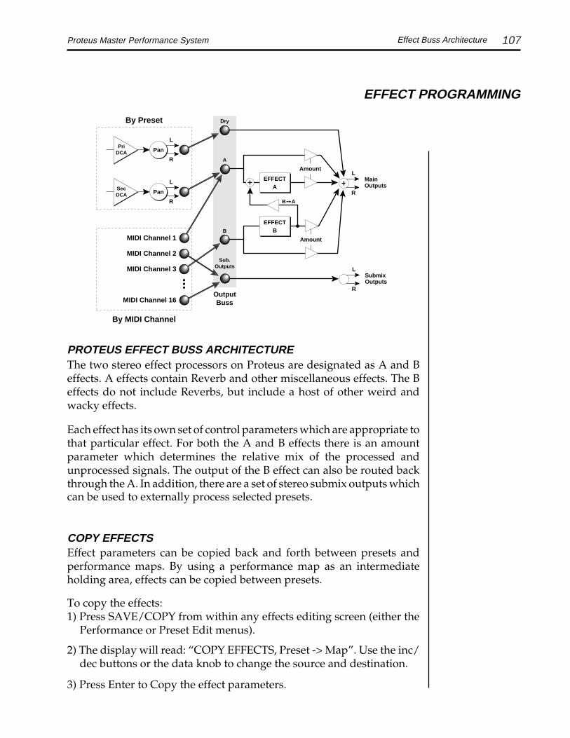
107Proteus Master Performance System
EFFECT PROGRAMMING
Effect Buss Architecture
L
R
L
R
EFFECTA
Amount
EFFECTB
Amount
Pan
L
R
Pan
L
R
PriDCA
SecDCA
SubmixOutputs
MainOutputs
OutputBuss
BA
B
A
Dry
Sub.Outputs
By Preset
By MIDI Channel
MIDI Channel 1
MIDI Channel 2
MIDI Channel 3
MIDI Channel 16
PROTEUS EFFECT BUSS ARCHITECTUREThe two stereo effect processors on Proteus are designated as A and Beffects. A effects contain Reverb and other miscellaneous effects. The Beffects do not include Reverbs, but include a host of other weird andwacky effects.
Each effect has its own set of control parameters which are appropriate tothat particular effect. For both the A and B effects there is an amountparameter which determines the relative mix of the processed andunprocessed signals. The output of the B effect can also be routed backthrough the A. In addition, there are a set of stereo submix outputs whichcan be used to externally process selected presets.
COPY EFFECTSEffect parameters can be copied back and forth between presets andperformance maps. By using a performance map as an intermediateholding area, effects can be copied between presets.
To copy the effects:1) Press SAVE/COPY from within any effects editing screen (either the
Performance or Preset Edit menus).
2) The display will read: “COPY EFFECTS, Preset -> Map”. Use the inc/dec buttons or the data knob to change the source and destination.
3) Press Enter to Copy the effect parameters.

108 Proteus Master Performance System
EFFECT PROGRAMMING
A EFFECTS
Room, Warm RoomPlates 1 and 2Chambers 1 and 2Halls 1 and 2
Delay, Cross DelayPhaserStereo FlangeStereo ChorusEchoStereo EQ
Small Rooms 1 and 2Hall 3Early Reflections 1, 2, 3 and 4Rain
A Effects
When using singlepresets, the effect pro-grammed in the PresetEdit menu is used.
When using multiplepresets, (Multi-mode),the effects selected inthe Performance Editmenu are used.
B EFFECTS
Stereo FlangeStereo ChorusPhaserFuzz 1Ring ModulatorDelayCross DelayStereo EQFuzz Lite
REVERBThe A effects are the most commonly used because they include reverb.Reverberation is a simulation of a natural space such as a room or hall. Thereverb effects in Proteus simulate various halls, chambers, rooms andreverberation plates. In addition, there are several other reverb effectssuch as Early Reflections and Rain. There is only one adjustable param-eter on the reverb effects - Decay Time. Decay time is the time it takes forthe reflected sound from the room to decay or die away. The diagrambelow shows a generalized reverberation envelope. After an initial pre-delay period, the echos from the closest walls or ceiling are heard. Thesefirst echos or the early reflection cluster, vary greatly depending on the typeof room. Roughly 20 milliseconds after the reflection cluster, the actualreverberation begins and decays according to the time set by the decaytime parameter.
TIME
AM
PLI
TU
DE
PreDelay
Reverb
Decay Time
EarlyReflectionCluster

109Proteus Master Performance System
EFFECT PROGRAMMING
Reverbs
The Room programs simulate small rooms with high frequency absorp-tion caused by drapes and furniture. Plates simulate plate type reverbswith their tight, dense early reflections and sharp reverb build-up.Chambers simulate medium sized rooms with hard reflective surfaces.The Hall programs recreate the open, spacious ambience of a largeconcert hall. The Early Reflection programs consist of the reflectioncluster only without the reverb decay. These are similar to a multiple tapdelay line. Rain is a variation of the early reflection programs whichconsists of a dense group of short echos followed by longer echos.
FXA:Hall 1Decay Time: 165
Place the cursor underneath the reverb name and use the data entrycontrol (or the inc/dec buttons) to change the type of reverb. Moving thecursor to the lower line allows you to change the decay time of the reverb.Plate 2 decay times are the shortest and range from 0 - 127. The decay timesof the reverb programs range from 100 - 255. The decay time of the EarlyReflection programs range from 0-255.
ROOMMid-sized room (or gigantic-sized room depending on the decay time).
WARM ROOMMid-sized room with more high frequency absorption.
PLATE 1Nice tight, clean plate reverb.
PLATE 2Plate reverb with a shorter decay time.
CHAMBER 1Bright and resonant reverberation chamber.
CHAMBER 2Less bright and resonant reverberation chamber.
HALL 1Large concert hall with a very balanced and musical sound.

110 Proteus Master Performance System
EFFECT PROGRAMMING
Reverbs
HALL 2A large concert hall with a lighter, more airy atmosphere
SMALL ROOM 1A petite yet perky room, possibly in a country mansion with hardwoodfloors.
SMALL ROOM 2A bolder but still modest room, with a tall slanted ceiling and a ruffledcouch at one end.
HALL 3A small cathedral, with a few hanging tapestries, somewhere in the southof France. (Use Hall 3 with a long decay for an infinite reverb effect.)
EARLY REFLECTION GROUPThe early reflections group are a cross between delay effects and reverbeffects. There is no diffusion, so there is no buildup of dense reflections,only the discrete initial reflections of a reverb. This group is useful forthose sounds that cannot tolerate the fullness of a reverb, but need abigger image spread than a delay can provide.
EARLY REFLECTION 1A plucky early reflection effect, without the diffusion of a standardreverb. Compact reflection spread, similar to a tiled bathroom with amedium sized bath mat, and a full tub.
EARLY REFLECTION 2A broader reflection cluster, and a slightly different room shape. Again,early reflections only, no diffusion.
EARLY REFLECTION 3A still broader time domain reflection spread. Useful for nice stutterattacks, and multiplying a percussive attack into a strum-like cluster.
EARLY REFLECTION 4The longest time spread reflection cluster, with a rising impulse responseplacing the listener towards the back of an empty non-diffusing concreteoutdoor amphitheater, with wooden benches.
RAINA first-order simulation of rain falling on a metal roof, in a redwood groveon a foggy afternoon.

111Proteus Master Performance System
EFFECT PROGRAMMING
STEREO DELAYThe delay line is a stereo effect which can be used for doubling, echos orfixed formant comb filtering with completely independent delay timeand tap levels for the left and right sides. The delay is shown in thediagram below.
The Delay Time parameter is independently variable from 0 to 209milliseconds for both the left and right channels. The Tap Level param-eters control the amount of signal from the left and right delays as well ashow much signal from each is supplied to the Feedback control. Feedbackcontrols how many echos are produced. A setting of 0 produces only oneecho. The Delay line is incredibly stable even with large amounts offeedback. This quality allows the delay line to be used as a resonator,where it acts as a kind of oscillator when excited by an input signal.Infinite delay effects are also possible without the risk of runaway. Thestereo delay can function as two independent delay lines by panning theprimary and secondary instruments to the extreme left and right.
R Output
RightDelay
FeedbackAmount
R Input Delay
RightTap Level
L Output
LeftDelay
L Input
LeftTap Level
Delay
The stereo delay line can function as two independent digital delays by panning the primaryand secondary instruments to opposite sides.
Stereo Delay

112 Proteus Master Performance System
EFFECT PROGRAMMING
R Output
RightDelay
FeedbackAmount
R Input Delay
RightTap Level
L Output
LeftDelay
L Input
LeftTap Level
Delay
The outputs and the feedback paths cross over to the opposite channel to produce a ping-pong echo effect.
CROSS DELAYCross Delay is identical to the normal delay line except that the outputpaths and the feedback paths cross over to the opposite channel in orderto produce a ping-pong type of effect when reproduced in stereo. Delaytime is adjustable from 0 to 209 milliseconds. The Cross Delay is shownin the diagram below.

113Proteus Master Performance System
EFFECT PROGRAMMING
STEREO PHASERThe Stereo Phaser is similar to the flanger although it's effect is moresubtle. A phaser is a type of filter which creates a series of notches in thefrequency spectrum. This creates a swirly animation when used withharmonic-rich sounds such as strings and voices. It can also be used muchthe same as a chorus to thicken-up a thin sound or as a rotating speakersimulator.
FXA:Phaser FXA:PhaserLFO Rate 150 LFO Depth 100
FXA:Phaser FXA:PhaserMin Delay 015 Feedback +064
Stereo Phaser
R Output
L Output
PhaseShift
LFO
ModAmount
LFORate
InitialFreq.
FeedbackAmount
R Input
L Input
+ -

114 Proteus Master Performance System
EFFECT PROGRAMMING
R Output
L Output
Delay
LFO
LFODepth
LFORate
InitialDelay
FeedbackAmount
R Input
L Input
+ -
Stereo Flanger Block Diagram
The flanging effect was originally created using two tape recordersplaying identical recordings. By exactly synchronizing the two decks andthen slowing the speed of one by grasping the tape reel flanges, theflanging effect was born.
The flanger in the Proteus is a stereo device consisting of two separatedelay lines controlled by a single set of controls. The block diagram of theflanger is shown below.
FREQUENCY (log)
AM
PLI
TU
DE
(dB
)
Notches
STEREO FLANGERA flanger consists of a short audio delay line whose output is mixedtogether with the original signal. Mixing the delayed and original signalstogether results in multiple frequency cancellations creating a comb filtereffect as shown in the diagram below. Since the flanger is a type of filter,it works best with harmonically rich sounds such as strings.
Stereo Flanger

115Proteus Master Performance System
EFFECT PROGRAMMING
An Initial Delay control serves to tune the flanger. In other words, itadjusts the placement of the comb filter notches. The initial delay isvariable from 26 microseconds to 6.5 milliseconds.
FXA:StereoFlangeInit Delay 100
A Low Frequency Oscillator (LFO) varies this initial delay setting,changing the frequency of the notches and adding animation to thesound. The LFO Rate controls the rate of change and the LFO Depthcontrols how much the delay is changed by the LFO. The LFO adds to theinitial delay time so that with LFO Depth set to 255 the maximum delaytime is 13 milliseconds.
FXA:StereoFlangeLFO Rate 038
FXA:StereoFlangeLFO Depth 150
The Feedback control sends some of the delayed signal through the delayline again. When positive feedback is used (values +1 to +127), the combfilter notches are deepened; when negative feedback is used (values -1 to-128) resonant peaks are formed between the notches which increase withthe amount of negative feedback.
FXA:StereoFlangeFeedback -150
Stereo Flanger
Panning the primaryand secondary instru-ments to opposite sidesallows each instrumentto be processed sepa-rately.

116 Proteus Master Performance System
EFFECT PROGRAMMING
Stereo Chorus
STEREO CHORUSThe function of a chorus device is to thicken the sound or to make onevoice sound like many. The way the effect is achieved is by mixing one ormore delayed versions of the signal in with the original. The delay timesused are too short to be perceived as a an echo, but long enough so thatcomb filtering does not occur. In addition, the delay time is varied tosimulate the random differences which occur when multiple instrumentsare playing together. A slight amount of feedback improves the effect bycreating multiple images of the sound as it recirculates again and again.The fact the delay times are slightly different for the left and rightchannels and your stereo speakers are in different room locations bothcontribute to the overall chorus effect. The LFO Rate and Depth settingsare critical to achieving a realistic effect with faster LFO Rates generallyrequiring less LFO Amount and vice-versa.
The stereo chorus in the Proteus works exactly like the previouslydescribed stereo flanger except that the delay time is longer. The delaytimes for the stereo chorus range from 13 milliseconds to 52 milliseconds,compared with the 26 microsecond to 6.5 millisecond range of the flanger.
FXA:StereoChorusLFO Rate 050
FXA:StereoChorusLFO Depth 050
FXA:StereoChorusMin Delay 036
FXA:StereoChorusFeedback 100
FXA:StereoChorusMix 050
LFO Rate varies the speed ofthe LFO.
LFO Depth sets the amountof LFO controllingthe delay time.
Min Delay sets the initial delaytime.
Feedback controls the amountof delayed signalsent back throughthe delay line.
Mix controls the mix ofdelayed and drysignal.

117Proteus Master Performance System
EFFECT PROGRAMMING
STEREO ECHOThe Stereo Echo produces echos up to 400 milliseconds in length (twicethat of the Delay and Cross Delay effects). The feedback path is indepen-dent of the output level and contains a low pass filter which simulates ananalog tape echo. The left and right signals are kept completely indepen-dent throughout the effect and have separate controls except for thefeedback amount control which affects both channels.
R Output
RightDelay
FeedbackAmount
R Input Delay
RightTap Level
L Output
LeftDelay
L Input
LeftTap Level
Delay
LowPass
LowPass
Max Delay = 400mS
FXA:EchoL DelayTime 120
FXA:EchoL Tap Level 255
FXA:EchoFeedback 100
Delay - varies the delay timefrom 0-400 mS.
Tap Level - controls the volumeof each channel.
Feedback - controls the numberof echos from bothchannels.
Stereo Echo
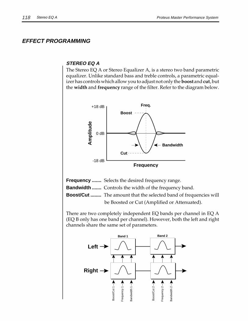
118 Proteus Master Performance System
EFFECT PROGRAMMING
STEREO EQ AThe Stereo EQ A or Stereo Equalizer A, is a stereo two band parametricequalizer. Unlike standard bass and treble controls, a parametric equal-izer has controls which allow you to adjust not only the boost and cut, butthe width and frequency range of the filter. Refer to the diagram below.
Boost
Cut
Freq.
0 dB
+18 dB
-18 dB
Bandwidth
Frequency
Am
plit
ud
e
Boo
st/C
ut 1
Fre
quen
cy 1
Ban
dwid
th 1
Boo
st/C
ut 2
Fre
quen
cy 2
Ban
dwid
th 2
Left
Right
Band 1 Band 2
Frequency ....... Selects the desired frequency range.Bandwidth ....... Controls the width of the frequency band.Boost/Cut ........ The amount that the selected band of frequencies will
be Boosted or Cut (Amplified or Attenuated).
There are two completely independent EQ bands per channel in EQ A(EQ B only has one band per channel). However, both the left and rightchannels share the same set of parameters.
Stereo EQ A

119Proteus Master Performance System
EFFECT PROGRAMMING
USING THE EQUALIZERThe equalizer can be used in a number of ways. It can be used to radicallyalter the sound of the samples so that a string section sounds like a stringsynthesizer, or can be used to fine tune your presets in the most subtleway. Samples can be completely transformed using the equalizer, multi-plying the number of possible sounds.
When using the EQ (either A or B), turn up the Effects Amount to 100%.Otherwise the EQ effect will be severely diluted as a result of beingmixed with the unprocessed signal.
A parametric equalizer can be a little confusing at first, especially if youhaven't worked with one before. First off, we have to find the band offrequencies that we want to boost or cut. Turn up the boost to about +15dB (so we can easily hear the effect of the EQ). Next, set the Bandwidth toabout 45 (which corresponds to about 100 Hz). Now slowly sweep thefrequency up and down. Stop when you find the band of interest andwiden the bandwidth (wider bandwidths tend to sound more musical).Finally, adjust the Boost control to the desired amount. Play with theBandwidth and Boost controls until the sound is to your liking.
The Equalizer can also function as a shelving type of EQ by setting thebandwidth very wide and moving the frequency parameter close to theends of the frequency range. The diagram below shows a High ShelvingFilter. A Low Shelving Filter could be created by moving the Frequencyparameter to the lower end of the frequency spectrum.
0
+18
-18Frequency
Am
plit
ud
e
Frequency
Bandwidth
Using Stereo EQ A
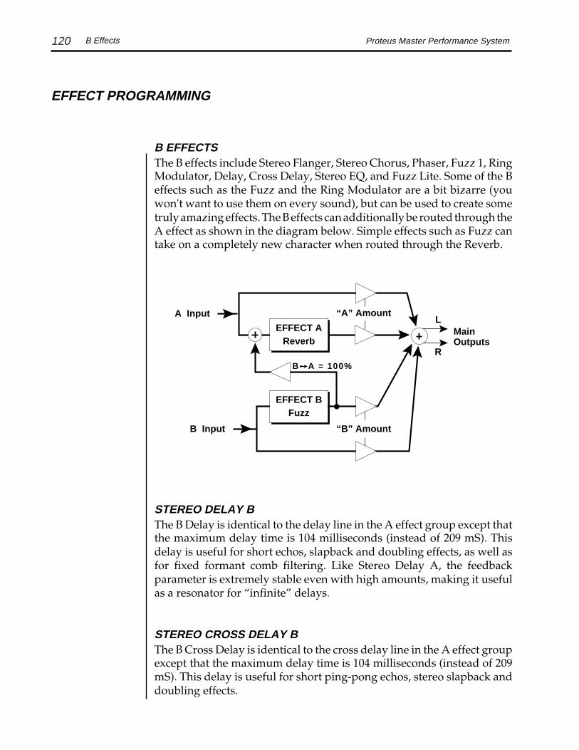
120 Proteus Master Performance System
EFFECT PROGRAMMING
B EFFECTSThe B effects include Stereo Flanger, Stereo Chorus, Phaser, Fuzz 1, RingModulator, Delay, Cross Delay, Stereo EQ, and Fuzz Lite. Some of the Beffects such as the Fuzz and the Ring Modulator are a bit bizarre (youwon't want to use them on every sound), but can be used to create sometruly amazing effects. The B effects can additionally be routed through theA effect as shown in the diagram below. Simple effects such as Fuzz cantake on a completely new character when routed through the Reverb.
B Effects
STEREO DELAY BThe B Delay is identical to the delay line in the A effect group except thatthe maximum delay time is 104 milliseconds (instead of 209 mS). Thisdelay is useful for short echos, slapback and doubling effects, as well asfor fixed formant comb filtering. Like Stereo Delay A, the feedbackparameter is extremely stable even with high amounts, making it usefulas a resonator for “infinite” delays.
STEREO CROSS DELAY BThe B Cross Delay is identical to the cross delay line in the A effect groupexcept that the maximum delay time is 104 milliseconds (instead of 209mS). This delay is useful for short ping-pong echos, stereo slapback anddoubling effects.
L
R
“B” Amount
MainOutputs
BA = 100%
EFFECT BFuzz
“A” Amount
B Input
A Input
EFFECT AReverb

121Proteus Master Performance System
EFFECT PROGRAMMING
STEREO EQ BThe Stereo EQ B or Stereo Equalizer B, is a stereo single band parametricequalizer. Unlike standard bass and treble controls, a parametric equal-izer has controls which allow you to adjust not only the boost and cut, butthe width and frequency range of the filter. This EQ differs from EQ A inthat it only has a single filter band per channel. Another difference is thatthe left and right channels are independently adjustable, unlike EQ A inwhich the left and right controls are ganged. Refer to the diagram below.
Boost/C
ut
Bandw
idth
Left
Right
Boo
st/C
ut
Fre
quen
cy
Ban
dwid
th
Frequency
Frequency.. Selects the desired frequency range.Bandwidth . Controls the width of the frequency band.Boost/Cut... The amount that the selected band of frequencies will
be Boosted or Cut (Amplified or Attenuated).
When using the EQ (either A or B), turn up the Effects Amount to 100%.Otherwise the EQ effect will be severely diluted as a result of beingmixed with the unprocessed signal.
Stereo EQ B
See Stereo EQ A foradditional programmingtips.

122 Proteus Master Performance System
EFFECT PROGRAMMING
Stereo Fuzz
STEREO FUZZThe Stereo Fuzz introduces a controlled distortion to any signal passingthrough it. Distortion creates harmonics. Simple sounds will becomecomplex sounds and complex sounds will become even more complex tothe point of becoming noise in many cases. There are two types of fuzz inthe Proteus effects arsenal, Fuzz 1 and Fuzz Lite.
FUZZ 1Fuzz 1 is probably the grungiest fuzz you have ever heard. Two filters,one at the input and one at the output of the fuzz, allow you to control theamount and type of harmonics added to the sound. The Input Filtercontrols the amount of harmonics produced by the fuzz and the OutputFilter removes harmonics at the output, smoothing the sound. Highervalues allow more harmonics to pass. The level of the input sound greatlyaffects the amount of fuzz, so that the Proteus' envelopes can now controlharmonic content as well as the volume. Output Level sets the output ofthe fuzz. There are two complete fuzz effects, controlled by the same setof controls as shown in the diagram below.
Two independent sounds can be processed by panning primary andsecondary to opposite sides, or a single sound can be routed through bothsides. If a single sound is panned slightly off center, the fuzz will actslightly differently on each side because of the difference in level.
R Output
L OutputFuzz
Fuzz
R
L
Pan
R
PriDCA
Pan
LSecDCA
Primary and Secondary instruments can be separately processed by panning to opposite sides.
R OutputR Input
L Input L OutputInputFilter Fuzz
OutputFilter
(LowPass) (LowPass)
InputFilter Fuzz
OutputFilter
(LowPass) (LowPass)
OutputLevel
OutputLevel

123Proteus Master Performance System
EFFECT PROGRAMMING
Fuzz Lite
You may want to run the output of the fuzz back through a reverb effectusing the B->A feedback mixer in the FX amount screen. (Try it!) Byadjusting the three amounts you can precisely control the amount ofOriginal Signal, Dry Fuzz Signal, and Reverb Fuzz Signal.
FX AMOUNT A:50%B>A:100% B:50%
FUZZ LITEFuzz Lite is a more restrained type of fuzz (it tastes great, yet is less filling).According to the designer, “Fuzz Lite is a mathematical model of a Soviet made6L6 vacuum tube, using the results of recent Neural Network modeling. Thisfuzz is much less aggressive than the existing fuzz, suitable for guitar overdrive,innovative new waveform distortion signals, and general fried brain full frontalinstruments.” Yeah.
Experiment with the way the input and output filters work on the sound.Like the Ring Modulator, the Stereo Fuzz is a specialized effect, not forevery situation, but another powerful tool in your arsenal.
FXB:Fuzz LiteInputFilter 100
L
R
“B” Amount
MainOutputs
BA = 100%
EFFECT BFuzz
“A” Amount
B Input
A Input
EFFECT AReverb
Using the B->A parameter allows the stereo fuzz to be followed by stereo reverb.

124 Proteus Master Performance System
EFFECT PROGRAMMING
FREQUENCY (Hz)A
MP
LIT
UD
E
200
FREQUENCY (Hz)
AM
PLI
TU
DE
800
FREQUENCY (Hz)
AM
PLI
TU
DE
200 600 800 1000
Left
Right
Result
200 Hz
800 Hz
600 &1000 Hz
(pri)
(sec)
This diagram shows the result of Ring Modulating two sine waves with frequencies of 200 Hzand 800 Hz. Only the Sum and Difference frequencies of 600 Hz and 1000 Hz will result.
Ring Modulator
RING MODULATORA Ring Modulator is a simple device which takes two signals andmultiplies them together into one resultant signal containing only thesum and difference frequencies of the two input waves. The originalfrequencies are not output! Ring modulators tend to generate a lot ofinharmonic frequencies which sound very bell-like and sometimes out oftune.

125Proteus Master Performance System
EFFECT PROGRAMMING
R
L
R Output
L Output
RingModulatorPan
R
PriDCA
Pan
LSecDCA
Ring Modulator
There are no controls on the ring modulator as shown by the blockdiagram below. The left and right outputs are simply multiplied togetherto form a monophonic output.
By routing both the primary and secondary sounds to effect B andpanning to opposite sides (shown below), two different waves can be ringmodulated. Ring modulation works well with simple waves such as sinewaves and the harmonic waveforms. Also, try complex waves modulatedwith sine waves. (Play chords!) Complex waveforms tend to sound rathernoise-like.
Pan the primary and secondary instruments to left and right in the panscreen, then move to the Effect B screen and select Ring Modulator. Thereare no parameters to adjust in this effect so the lower line of the displayreads: None.
FXB: Ring ModNone
R Output
L Output
RingModulator
R Input
L Input

126 Proteus Master Performance System
EFFECT PROGRAMMING

127Proteus Master Performance System Reference
REFERENCE SECTION

128 Proteus Master Performance SystemROM Presets
PROTEUS ROM PRESETS
KEYBOARDS000 Dark Grand008 Heavens Sake020 Prok'l Harem023 Soft Electric Piano033 Concert Keys034 Mellow Piano050 Chorused Clav060 Church071 Pianoharp076 Ring MoD081 Rock Piano086 Med Electric Piano088 Ham'nd Cheese096 Harpsikord
STRINGS002 Orchestral!012 Inxs Strings022 Orchestra Hit032 Strings/Horns043 Omnimax051 Sforz Strings082 New Orchestra
VOICES005 Chorus Choir016 Herb Essence035 Dirty Pad055 Master Choir
BRASS004 Brass Section024 Solo Trumpet032 Strings/Horns038 Big City Brass040 French Horn Section044 Solo Trombone047 Exhibition
REEDS/FLUTES007 Sweet'n' Saxy017 Chiff Whiff057 Bari/Alto Sax068 Big Band Sax089 Verb Flute
PLUCKED006 Major Solo013 Acoustic Gtr026 Agent Cooper036 Funk Guitar046 Power Chords056 Modern Harp067 Swirl'n Git072 Rock Solo077 Rock 5ths083 12 String094 Electric 12
* Denotes a linked preset.

129Proteus Master Performance System
PROTEUS ROM PRESETS
ROM Presets
SYNTHESIZER001 Shimmer Waves003 Metallivox014 New Age Solo025 Sezdin Nites030 Ice Forest037 Wayoo041 Phantazia045 Spun Glass052 Synth Pad054 Wynwood Solo061 Stagger Waves *063 Synth Quartet073 UK Pad080 Waves087 Voiceofmind090 Harmonic Syn097 Waves…2 *
BASS010 Miracle Bass018 Bad Bass029 Cosmo Low Man059 Analog Bass066 Fat Bass070 Thunder Bass079 Slap/Pop Bass085 Fat Boy Bass093 Last Bass
TUNEDPERCUSSION015 Vibe n Me069 Airimba075 Cosmo Bells078 Wide Marimba
PERCUSSION009 Pop Percussion027 Latin Drums028 Latin Percussion039 Yin Yang Percussion058 Concert Percussion065 Rock Drums084 Rez Flange Kit091 Tusk Toms092 Slave Percussion098 Machine Snare
WORLD019 Kalimba Synth048 Island Fun062 Balinesia
SOUND EFFECTS011 Metal Cables021 Waterfone031 Synthyricon042 Planet X053 Underground064 Lost Souls095 Waterways
099. Default Patch
* Denotes a linked preset.

130 Proteus Master Performance System
SAMPLED SOUNDS1. Piano ........................................................................... 9 foot Grand Piano2. Piano Pad .......................... Piano with slow attack and sustained loop3. Loose Piano .......................................................... Old style Grand Piano4. Tight Piano...................................... Contemporary 9 foot Grand Piano5. Strings .............. String section with Basses, Cellos, Violas and Violins6. Long Strings...................... String section with long attack and release7. Slow Strings ................. Section Strings with longer attack and release8. Dark Strings ..................................... Section Strings with a darker tone9. Voices.................................................................................... Female Choir10. Slow Voices ................... Female Choir with longer attack and release11. Dark Choir ........................................ Female Choir with a darker tone12. Synth Flute ......................................... Genuine Flute with a short loop13. Soft Flute ..................................................................... Slow attack Flute14. Alto Sax ....................................................................................... Alto Sax15. Tenor Sax.................................................................................. Tenor Sax16. Baritone Sax ......................................................................... Baritone Sax17. Dark Sax .................................................. Tenor sax with a darker tone18. Soft Trumpet .......................................................... Soft blown Trumpet19. Dark Soft Trumpet .............. Soft blown Trumpet with a darker tone20. Hard Trumpet ..................................................... Hard blown Trumpet21. Dark Hard Trumpet ......... Hard blown Trumpet with a darker tone22. Horn Falls ................................................. Descending pitch Trumpets23. Trombone 1 .............................................................................. Trombone24. Trombone 2 ............................................................................. Trombone25. French Horn........................................................................ French Horn26. Brass 1 .................................... Combination Trombone/Soft Trumpet27. Brass 2 .................................. Combination Trombone/Hard Trumpet28. Brass 3 ........ Combination Trombone/Soft Trumpet/Hard Trumpet29. Trombone/Sax ................................ Combination Trombone and Sax30. Guitar Mute .............................................. Palm muted Electric Guitar31. Electric Guitar............................. Clean, Humbucking Electric Guitar32. Acoustic Guitar ........................................ Steel String Acoustic Guitar33. Rock Bass ...................................................... Carbon Fiber Bass Guitar34. Stone Bass .................................... Rare, Aluminum Neck Bass Guitar35. Flint Bass ..................................... Bass Guitar with altered harmonics36. Funk Slap .............................. Lower two Bass Guitar strings slapped37. Funk Pop ..... Popped Bass Guitar strings (combine with Funk Slap)38. Harmonics ......................................................... Bass Guitar Harmonics39. Rock/Harmonics ....... Combination Rock Bass and Bass Harmonics
PROTEUS INSTRUMENTS
Sampled Sounds

131Proteus Master Performance System
PROTEUS INSTRUMENTS
40. Stone/Harmonics .. Combination Alum. Neck Bass and Harmonics41. Nose Bass ................................................ Chunky, Popped Bass Guitar42. Bass Synth 1 ......................... Classic, Analog Synthesizer Bass Sound43. Bass Synth 2 ..................................................... Digital Bass Synthesizer44. Synth Pad .................................................. Fat, Digital Synthesizer pad45. Medium Envelope Pad ..... Digital Synth pad with altered envelope46. Long Envelope Pad. Digital Synth pad with long attack and release47. Dark Synth .............................. Digital Synthesizer with a darker tone48. Percussive Organ .......................... Classic, Tone Wheel Organ sound49. Marimba ..................................................................................... Marimba50. Vibraphone ........................................................................... Vibraphone51. All Percussion (balanced levels) ........52. All Percussion (unbalanced levels) ...53. Standard Percussion Setup 1 ..............54. Standard Percussion Setup 2 ..............55. Standard Percussion Setup 3 ..............56. Kicks ......................................................57. Snares.....................................................58. Toms ......................................................59. Cymbals ................................................60. Latin Drums..........................................61. Latin Percussion ...................................62. Agogo Bell .............................................63. Woodblock ............................................64. Conga.....................................................65. Timbale ..................................................66. Ride Cymbal .........................................67. Percussion FX1 .....................................68. Percussion FX2 .....................................69. Metal ....................... Percussive, Metallic, Analog Synthesizer Sound
See thePercussionInstrument LocationDiagramson the following pages.
Sampled Sounds
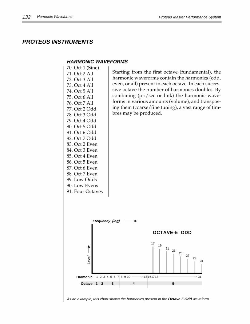
132 Proteus Master Performance System
PROTEUS INSTRUMENTS
HARMONIC WAVEFORMS70. Oct 1 (Sine)71. Oct 2 All72. Oct 3 All73. Oct 4 All74. Oct 5 All75. Oct 6 All76. Oct 7 All77. Oct 2 Odd78. Oct 3 Odd79. Oct 4 Odd80. Oct 5 Odd81. Oct 6 Odd82. Oct 7 Odd83. Oct 2 Even84. Oct 3 Even85. Oct 4 Even86. Oct 5 Even87. Oct 6 Even88. Oct 7 Even89. Low Odds90. Low Evens91. Four Octaves
Starting from the first octave (fundamental), theharmonic waveforms contain the harmonics (odd,even, or all) present in each octave. In each succes-sive octave the number of harmonics doubles. Bycombining (pri/sec or link) the harmonic wave-forms in various amounts (volume), and transpos-ing them (coarse/fine tuning), a vast range of tim-bres may be produced.
Harmonic Waveforms
As an example, this chart shows the harmonics present in the Octave 5 Odd waveform.
1 2 3 4 5 6 7 8 9 10 15 1617 3118
1 2 3 4 5
Harmonic
Octave
Frequency (log)
Lev
el
OCTAVE-5 ODD
1719
2123
2527
2931

133Proteus Master Performance System
SINGLE CYCLE WAVEFORMS92. Synth Cycle 193. Synth Cycle 294. Synth Cycle 395. Synth Cycle 496. Fundamental Gone 197. Fundamental Gone 298. Bite Cycle99. Buzzy Cycle 1100. Metalphone 1101. Metalphone 2102. Metalphone 3103. Metalphone 4104. Duck Cycle 1105. Duck Cycle 2106. Duck Cycle 3107. Wind Cycle 1108. Wind Cycle 2109. Wind Cycle 3110. Wind Cycle 4111. Organ Cycle 1112. Organ Cycle 2
MULTI-CYCLE WAVEFORMS113. Noise114. Stray Voice 1115. Stray Voice 2116. Stray Voice 3117. Stray Voice 4118. Synth String 1119. Synth String 2120. Animals121. Reed122. Pluck 1123. Pluck 2124. Mallet 1125. Mallet 2
PROTEUS INSTRUMENTS
The multi-cycle cycle waveforms areshort sections of sampled sounds.
These single cycle waveforms wereeither synthesized or taken from ac-tual sampled sounds. They werechosen for their diversity and inter-esting qualities.
Waveforms
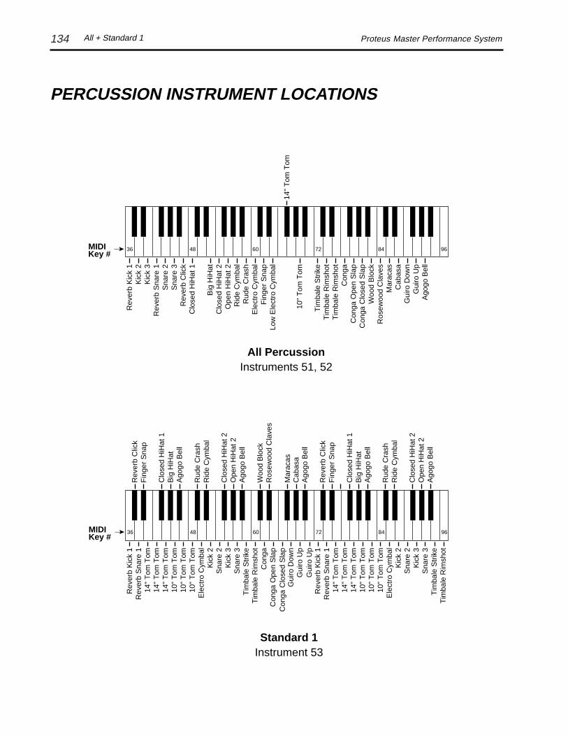
134 Proteus Master Performance System
Rev
erb
Kic
k 1
Kic
k 2
Kic
k 3
Rev
erb
Sna
re 1
Sna
re 2
Sna
re 3
Rev
erb
Clic
kC
lose
d H
iHat
1
Big
HiH
atC
lose
d H
iHat
2O
pen
HiH
at 2
Rid
e C
ymba
lR
ude
Cra
shE
lect
ro C
ymba
lF
inge
r S
nap
Low
Ele
ctro
Cym
bal
Tim
bale
Str
ike
Con
gaC
onga
Ope
n S
lap
Woo
d B
lock
Mar
acas
Cab
asa
Ago
go B
ell
14"
Tom
Tom
10"
Tom
Tom
Tim
bale
Rim
shot
Tim
bale
Rim
shot
Con
ga C
lose
d S
lap
Ros
ewoo
d C
lave
s
Gui
ro D
own
Gui
ro U
p
MIDIKey #
36 48 60 72 84 96
All PercussionInstruments 51, 52
PERCUSSION INSTRUMENT LOCATIONS
Gui
ro D
own
Gui
ro U
p
Con
ga O
pen
Sla
pC
onga
Tim
bale
Rim
shot
Tim
bale
Str
ike
Sna
re 3
Kic
k 3
Sna
re 2
Kic
k 2
10"
Tom
Tom
10"
Tom
Tom
10"
Tom
Tom
14"
Tom
Tom
14"
Tom
Tom
Rev
erb
Sna
re 1
Rev
erb
Kic
k 1
14"
Tom
Tom
Rev
erb
Clic
k
Clo
sed
HiH
at 1
Big
HiH
at
Clo
sed
HiH
at 2
Ope
n H
iHat
2
Rid
e C
ymba
lR
ude
Cra
sh
Ago
go B
ell
Fin
ger
Sna
p
Woo
d B
lock
Mar
acas
Cab
asa
Ago
go B
ell
Ros
ewoo
d C
lave
s
Ele
ctro
Cym
bal
Con
ga C
lose
d S
lap
Gui
ro U
p
Ago
go B
ell
Tim
bale
Rim
shot
Tim
bale
Str
ike
Sna
re 3
Kic
k 3
Sna
re 2
Kic
k 2
10"
Tom
Tom
10"
Tom
Tom
10"
Tom
Tom
14"
Tom
Tom
14"
Tom
Tom
Rev
erb
Sna
re 1
Rev
erb
Kic
k 1
14"
Tom
Tom
Ele
ctro
Cym
bal
Rev
erb
Clic
k
Clo
sed
HiH
at 1
Big
HiH
at
Clo
sed
HiH
at 2
Ope
n H
iHat
2
Rid
e C
ymba
lR
ude
Cra
sh
Ago
go B
ell
Fin
ger
Sna
p
Ago
go B
ell
Standard 1
MIDIKey #
36 48 60 72 84 96
Instrument 53
All + Standard 1

135Proteus Master Performance System
Gui
ro D
own
Gui
ro U
p
Con
ga O
pen
Sla
pC
onga
Tim
bale
Rim
shot
Tim
bale
Str
ike
Sna
re 2
Kic
k 2
Rev
erb
Sna
re 1
Rev
erb
Kic
k 1
10"
Tom
Tom
10"
Tom
Tom
10"
Tom
Tom
14"
Tom
Tom
14"
Tom
Tom
Sna
re 3
Kic
k 3
14"
Tom
Tom
Rev
erb
Clic
k
Clo
sed
HiH
at 2
Ope
n H
iHat
2
Clo
sed
HiH
at 1
Big
HiH
at
Rid
e C
ymba
lR
ude
Cra
sh
Ele
ctro
Cym
bal
Fin
ger
Sna
p
Woo
d B
lock
Mar
acas
Cab
asa
Ago
go B
ell
Ros
ewoo
d C
lave
s
Hi E
lect
ro C
ymba
l
Con
ga C
lose
d S
lap
Gui
ro U
p
Ele
ctro
Cym
bal
Tim
bale
Rim
shot
Tim
bale
Str
ike
Sna
re 2
Kic
k 2
Rev
erb
Sna
re 1
Rev
erb
Kic
k 1
10"
Tom
Tom
10"
Tom
Tom
10"
Tom
Tom
14"
Tom
Tom
14"
Tom
Tom
Sna
re 3
Kic
k 3
14"
Tom
Tom
Ele
ctro
Cym
bal
Rev
erb
Clic
k
Clo
sed
HiH
at 2
Ope
n H
iHat
2
Clo
sed
HiH
at 1
Big
HiH
at
Rid
e C
ymba
lR
ude
Cra
sh
Ele
ctro
Cym
bal
Fin
ger
Sna
p
Ele
ctro
Cym
bal
Standard 3
MIDIKey #
36 48 60 72 84 96
Instrument 55
Gui
ro D
own
Gui
ro U
p
Con
ga O
pen
Sla
pC
onga
Tim
bale
Rim
shot
Tim
bale
Str
ike
Sna
re 3
Kic
k 3
Rev
erb
Sna
re 1
Rev
erb
Kic
k 1
10"
Tom
Tom
10"
Tom
Tom
10"
Tom
Tom
14"
Tom
Tom
14"
Tom
Tom
Sna
re 2
Kic
k 2
14"
Tom
Tom
Rev
erb
Clic
k
Clo
sed
HiH
at 2
Ope
n H
iHat
2
Clo
sed
HiH
at 1
Big
HiH
at
Rid
e C
ymba
lR
ude
Cra
sh
Ele
ctro
Cym
bal
Fin
ger
Sna
p
Woo
d B
lock
Mar
acas
Cab
asa
Ago
go B
ell
Ros
ewoo
d C
lave
s
Ele
ctro
Cym
bal
Con
ga C
lose
d S
lap
Gui
ro U
p
Ele
ctro
Cym
bal
Tim
bale
Rim
shot
Tim
bale
Str
ike
Sna
re 3
Kic
k 3
Rev
erb
Sna
re 1
Rev
erb
Kic
k 1
10"
Tom
Tom
10"
Tom
Tom
10"
Tom
Tom
14"
Tom
Tom
14"
Tom
Tom
Sna
re 2
Kic
k 2
14"
Tom
Tom
Ele
ctro
Cym
bal
Rev
erb
Clic
k
Clo
sed
HiH
at 2
Ope
n H
iHat
2
Clo
sed
HiH
at 1
Big
HiH
at
Rid
e C
ymba
lR
ude
Cra
sh
Ele
ctro
Cym
bal
Fin
ger
Sna
p
Ele
ctro
Cym
bal
Standard 2
MIDIKey #
36 48 60 72 84 96
Instrument 54
PERCUSSION INSTRUMENT LOCATIONS
Standard percussion setups 1, 2, and 3 are compatible with the Alesis HR16,Korg M1, Dr. T's "Dr. Drum" patterns as well as other devices and programs.
Standard 2 + 3

136 Proteus Master Performance System
Toms
14" Tom Tom
10" Tom Tom
MIDIKey #
36 48 60 72 84 96
Instrument 58
Snares
Reverb Snare 1 Snare 2
Snare 3
MIDIKey #
36 48 60 72 84 96
Instrument 57
Kicks
Reverb Kick 1
Kick 2
Kick 3
MIDIKey #
36 48 60 72 84 96
Instrument 56
PERCUSSION INSTRUMENT LOCATIONS
Kicks, Snares, Toms

137Proteus Master Performance System
Latin Percussion
Guiro Down
Claves
Electro Cymbal Agogo Bell
WoodBlockGuiro UpCabasaMaracas
MIDIKey #
36 48 60 72 84 96
Instrument 61
Instrument 60Latin Drums
Tim
bale
Rim
shot
Tim
bale
Str
ike
Tim
bale
Rim
shot
Tim
bale
Str
ike
Con
ga O
pen
Sla
pC
onga
Ope
n S
lap
Con
gaC
onga
Con
ga O
pen
Sla
p
Con
ga
Con
ga O
pen
Sla
pC
onga
Ope
n S
lap
Con
gaC
onga
Con
ga O
pen
Sla
p
Con
ga C
lose
d S
lap
Con
ga C
lose
d S
lap
Con
ga C
lose
d S
lap
Con
ga C
lose
d S
lap
Con
ga C
lose
d S
lap
Con
ga C
lose
d S
lap
Con
ga C
lose
d S
lap
Con
ga C
lose
d S
lap
Con
ga C
lose
d S
lap
Con
ga C
lose
d S
lap
Con
ga O
pen
Sla
pC
onga
Con
gaC
onga
Con
ga O
pen
Sla
p
Tim
bale
Str
ike
Tim
bale
Str
ike
Tim
bale
Rim
shot
Tim
bale
Str
ike
Tim
bale
Str
ike
Tim
bale
Rim
shot
Con
ga C
lose
d S
lap
Tim
bale
Str
ike
Tim
bale
Rim
shot
Tim
bale
Rim
shot
Tim
bale
Str
ike
Tim
bale
Rim
shot
Tim
bale
Rim
shot
Tim
bale
Str
ike
TimbaleRimshot
Timbale Strike
MIDIKey #
36 48 60 72 84 96
PERCUSSION INSTRUMENT LOCATIONS
Cymbals
Closed HiHat 1
Big HiHat Closed HiHat 2 Open HiHat 2
Ride Cymbal Rude Crash
MIDIKey #
36 48 60 72 84 96
Instrument 59
Cymbals + Latin

138 Proteus Master Performance System
Agogo Bell, Conga, Ride CymbalInstruments 62, 64, 66
Agogo BellCongaRide Cymbal
MIDIKey #
36 48 60 72 84 96
Percussion FX 2
Conga Open Slap
Ride Cymbal
Big HiHat
MIDIKey #
36 48 60 72 84 96
Instrument 68
Percussion FX 1
ReverbSnare 1
ReverbClick
RudeCrash
GuiroUp
CongaOpen Slap
FingerSnap
BigHiHat
ElectroCymbal
RideCymbal
OpenHiHat
2
MIDIKey #
36 48 60 72 84 96
Instrument 67
PERCUSSION INSTRUMENT LOCATIONS
FX 1 + 2

139Proteus Master Performance System Parameter Charts
PROTEUS PARAMETER CHARTS
LFO RATESRate (Hz)
40
127806050
30252015105
000Knob
3.3
2516107
2.21.81.33
.8
.6
.1.052
AUXILIARYATTACK
Time (sec)
50
99887560
403020151050
Knob
5.25
13699239
2.751.5.8.5
.25.125
0
HOLDTime (sec)
60
99807570
504030201050
Knob
2.3
6.54.23.53.2
1.751.3.8.4
.25.125
0
DECAYTime (sec)
60
99807570
504030201050
Knob
5
4018129
31.5.75.4.25.125
0
RELEASETime (sec)
50
99807560
403020151050
Knob
4
6020159
2.21.2.6.4.25.125
0
VOLUMEATTACK
Time (sec)
50
99807560
403020151050
Knob
4
6020159
2.21.2.6.4
.25.125
0
INSTRUMENT/ENVELOPE
DELAYTime (sec)
75
1271009680
64403220105
000Knob
3.5
137
6.24.2
2.51.51.6.25.125
0
EQBANDWIDTH
Freq (Hz)
84
12712010896
7260483624120
Knob
868
9000615032021667
452235
122.56433179
B DELAYTime (mS)
125
255200175150
10075503020105
Knob
50
103817160
40302012842
EQFREQUENCY
Freq (Hz)
84
12712010896
7260483624120
Knob
3938
16000127358612
5823.5
266318011218823.553329148.5
A DELAYTime (mS)
125
255200175150
10075503020105
Knob
101
206161141121
816040241684
ECHO DELAY
125
255200175150
10075503020105
Knob
202
412323282242
161121814832168
Time (mS)
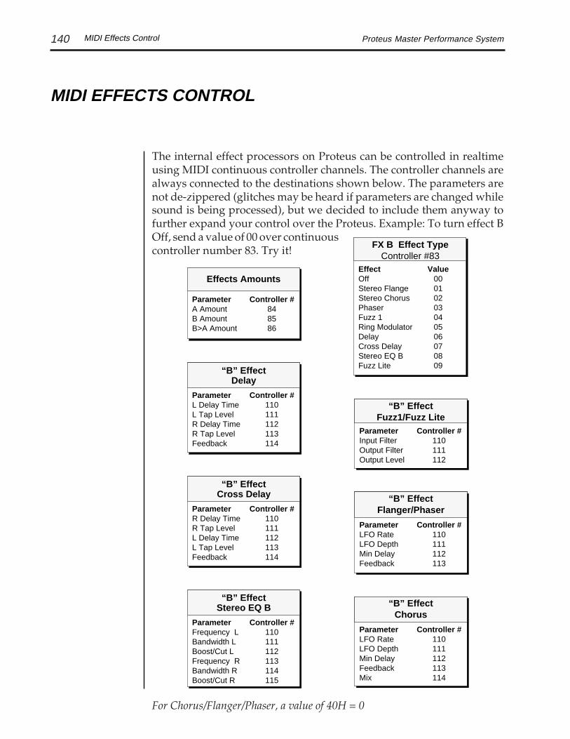
140 Proteus Master Performance SystemMIDI Effects Control
MIDI EFFECTS CONTROL
For Chorus/Flanger/Phaser, a value of 40H = 0
ParameterInput FilterOutput FilterOutput Level
Controller #110111112
“B” EffectFuzz1/Fuzz Lite
ParameterL Delay TimeL Tap LevelR Delay TimeR Tap LevelFeedback
Controller #110111112113114
“B” EffectDelay
ParameterLFO RateLFO DepthMin DelayFeedback
Controller #110111112113
“B” EffectFlanger/PhaserParameter
R Delay TimeR Tap LevelL Delay TimeL Tap LevelFeedback
Controller #110111112113114
“B” EffectCross Delay
ParameterLFO RateLFO DepthMin DelayFeedbackMix
Controller #110111112113114
“B” EffectChorus
ParameterFrequency LBandwidth LBoost/Cut LFrequency RBandwidth RBoost/Cut R
Controller #110111112113114115
“B” EffectStereo EQ B
ParameterA AmountB AmountB>A Amount
Controller #848586
Effects AmountsEffectOffStereo FlangeStereo ChorusPhaserFuzz 1Ring ModulatorDelayCross DelayStereo EQ BFuzz Lite
Value00010203040506070809
FX B Effect TypeController #83
The internal effect processors on Proteus can be controlled in realtimeusing MIDI continuous controller channels. The controller channels arealways connected to the destinations shown below. The parameters arenot de-zippered (glitches may be heard if parameters are changed whilesound is being processed), but we decided to include them anyway tofurther expand your control over the Proteus. Example: To turn effect BOff, send a value of 00 over continuouscontroller number 83. Try it!
.

141Proteus Master Performance System MIDI Effect Control
MIDI EFFECTS CONTROL
For Chorus/Flanger/Phaser, a value of 40H = 0
ParameterL Delay TimeL Tap LevelR Delay TimeR Tap LevelFeedback
Controller #7071727374
“A” EffectDelay/Echo
ParameterDecay Time
Controller #70
“A” EffectReverb Effects
ParameterR Delay TimeR Tap LevelL Delay TimeL Tap LevelFeedback
Controller #7071727374
“A” EffectCross Delay
ParameterLFO RateLFO DepthMin DelayFeedback
Controller #70717273
“A” EffectFlanger/Phaser
ParameterLFO RateLFO DepthMin DelayFeedbackMix
Controller #7071727374
“A” EffectChorus
ParameterFrequency 1Bandwidth 1Boost/Cut 1Frequency 2Bandwidth 2Boost/Cut 2
Controller #707172737475
“A” EffectStereo EQ
FX A Effect TypeController #82
EffectOffRoomWarm RoomPlate 1Plate 2Chamber 1Chamber 2Hall 1Hall 2DelayCross DelayPhaserStereo FlangeStereo ChorusEchoStereo EQ ASmall RoomSmall Room 2Hall 3Early Refl. 1Early Refl. 2Early Refl. 3Early Refl. 4Rain
Value000102030405060708090A0B0C0D0E0F1011121314151617
ParameterA AmountB AmountB>A Amount
Controller #848586
Effects Amounts
The A effects are controlled in the same way. As another example, tochange the reverb decay time, change the value of continuous controller#70 from your sequencer. You can see the changes in the Proteus display.

142 Proteus Master Performance System
TECHNICAL SPECIFICATIONS
Audio Channels: 32Audio Outputs: 4Submix Inputs: 2Max. Output Level: +6 dBVHeadphone Output Level: 60 mW into 60ΩOutput Impedance (main): 1 KΩMIDI: In, Out, ThruData Encoding: 16 bit LinearSignal to Noise: >90 dBDynamic Range: >90 dBFrequency Response: 20Hz-18kHzTHD +N: <.05%IMD: <.05%Stereo Phase: Phase Coherent
Power Requirements: 10 watts
Dimensions: H: 3.25" W: 13" L: 39.5"Weight: 22.8 lb (10.34 Kg)
Specifications

143Proteus Master Performance System
MIDI IMPLEMENTATION CHART
MIDI Implementation Chart
12/1/91
Function… Transmitted Recognized RemarksBasicChannel
DefaultChanged
11-16
11-16
Mode
DefaultMessages
Mode 1, 3, 4MONO, POLYOMNI ON/OFF
NoteNumber True Voice
0-1270-127
0-1270-127
Memorized
X Memorized
Velocity Note ONNote OFF
0X
0 v = 1-127X 8N
xmit rel. is ignoredv = 40H (64)
AfterTouch
KeysChannels
X0X
00X
Key = recognizedChan = xmit/recog
Pitch Bender 0X 0X 0-12 semitones
ControlChange
0X0 - 120
0X
ProgramChange True Number
0X 0-127 * 0-127
0X 0-127 * 0-127
System Exclusive 0 0
System
Common
:Song Pos:Song Sel:Tune
000
XXX
Any MIDI data upto 320 bytes can be transmitted
SystemReal Time
:Clock:Commands
XX
XX
Aux.Messages
:Local ON/OFF:All Notes Off:Active Sense:Reset
X0XX
00XX
Not Memorized
Notes: Reset Controls* Bank Change
000
Mode 1: OMNI ON, POLYMode 3: OMNI OFF, POLY
Mode 2: OMNI ON, MONOMode 4: OMNI OFF, MONO
Pan 0=hard left 127=hard right

144 Proteus Master Performance System
MIDI SPECIFICATIONS
Received Channel Commands
RECEIVED CHANNEL COMMANDSChannels number (n) = 0-15. Message bytes are represented in hex. Allother numbers are decimal.
Command Message Comments
Note Off 8n kk vv release velocity is ignored
Note Off 9n kk vv velocity 0 = note off
Key Pressure An kk pp
Program Change Cn pp
Channel Pressure Dn pp
Pitch Wheel En ll mm l = lsb, m = msb
Realtime Controller Bn cc vv cc = 00-31
PerformanceMap Select Bn 50 mm mm = map #
Quick Key Select Bn 51 qq qq = quickey #
Effect A Select Bn 52 ee ee = effect A #
Effect B Select Bn 53 ee ee = effect B #
Effect A Amount Bn 54 ee ee = effect A amount#
Effect B Amount Bn 55 ee ee = effect B amount#
Effect Series Amount Bn 56 ee ee = B->A effect amount#
Effect Assign Pri. Bn 57 ee ee = Pri. effect assign. value
In multi-mode, this selectseffect buss channelassignment.

145Proteus Master Performance System
RECEIVED CHANNEL COMMANDS (cont)
Command Message Comments
Effect Assign Sec. Bn 58 ee ee = Sec. effect assign. value
In multi-mode, this selectseffect buss channel assignment.
Effect AParameter Value Bn cc vv cc = 70-79 vv = parameter
value
Effect BParameter Value Bn cc vv cc = 110-119 vv = parameter
value
Footswitch Bn cc vv cc = 64-79, vv ≥ 64 = on
Volume Bn 07 vv
Pan Bn 0A vv 0 = hard left, 127 = hard right
Pan = “P” Bn 5A 40 sets pan to “P”
Reset All Controllers Bn 79 00 ignored in omni mode
Local Control Bn 7A vv 0 = off, ≥ 1 = on
All Notes Off Bn 7B 00 ignored in omni mode
Omni Mode Bn 7D 00 forces all notes & controls off
Mono Mode Bn 7E 00 forces all notes & controls off
Poly Mode Bn 7F 00 forces all notes & controls off
Bank Select Bn 00 mm 20 ll Cn pp
mm = msb, ll = lsbpp = preset within new bank
Bank Select is ignored if aProgram->Preset Map is turned on.
Received Channel Commands
MIDI SPECIFICATIONS

146 Proteus Master Performance System
RECEIVED SYSTEM COMMANDSFor system exclusive commands, the following format is used:
F0 system exclusive status byte18 E-mu ID byte08 product ID bytedd device ID bytecc command byte... data bytesF7 EOX
Two MIDI bytes (lsb, msb) are required for each 14 bit data word. Bits0-6 are sent first, followed by bits 7-13 in the next MIDI byte. All datawords are signed 2's complement values with sign-extension out to themost significant bit (bit 13). This convention applies to all data words,regardless of the parameter's value range.
Command Message Comments
Preset Data Request F0 18 id dd 00 ll mm F7 ll= preset # lsb,mm = msb
Preset Data F0 18 id dd 01 ll mm ... ... cs F7cs = checksum = sum of all data bytes
Parameter Value F0 18 id dd 02 pl pm F7Request pl = parameter # lsb pm = msb
Parameter Value F0 18 id dd 03 pl pm vl vm F7vl = value lsb vm = msb
Tuning Table Request F0 18 04 dd 04 F7 Original ProteusM.P.S. will send table #1
Tuning Table F0 18 04 dd 05 ... ... F7 Original Proteus
Tuning Table Request F0 18 08 dd 04 tt F7 Proteus M.P.S.tt = tuning table #
When Product ID 04is received, MIDIcommands areinterpreted andresponded to using theoriginal Proteus MIDIspecification.
Received System Commands
MIDI SPECIFICATIONS

147Proteus Master Performance System
RECEIVED SYSTEM COMMANDS (Continued)
Command Message Comments
Tuning Table F0 18 08 dd 05 ... ... F7 Proteus M.P.S.
Program Map Request F0 18 04 dd 06 F7 Original Proteus
Program Map Data F0 18 04 dd 07 ... ... F7 Original Proteus
Program Map Request F0 18 08 dd 06 mm F7 Proteus M.P.S.mm = map #
Program Map Data F0 18 08 dd 07 mm ... ... F7 Proteus M.P.S.mm = map #
Performance Map Req. F0 18 08 dd 14 rr F7 rr = map #
Performance Map Data F0 18 08 dd 15 rr ... ... F7 rr = map #
User Data Request F0 18 08 dd 16 rr F7 rr = map #
User Data F0 18 08 dd 17 rr ll ml lm mm ... ... cs F7rr=map #
ll=ls byte of ls wordml= ms byte of ls wordlm=ls byte of ms word
mm= ms byte of ms wordcs = checksum = sum of data bytes
Note: When Proteus sends Performance Map data (invoked from the Master Editmenu), it sends both the Performance Map data (message #15) and its corre-sponding User Data (message #17). This method splits up the performance mapinto two more manageable chunks of MIDI SysEx data and provides moreindependence and flexibility.
WARNING: When transferring preset banks back and forth from theProteus to a computer, the data should be recorded as you would a regularsequence. Sending the data in one huge chunk will choke the Proteus onplayback. In particular, utilities like the Master Tracks Pro4 Sysx loaderwill not work because they send the data all at once.
MIDI SPECIFICATIONS
Received System Commands

148 Proteus Master Performance System
MIDI SPECIFICATIONS
Parameter Editing
TRANSMITTED SYSTEM COMMANDS
Command Message Comments
Preset Data F0 18 id dd 01 ll mm ... ... CS F7
cs = checksum = sum of all data bytes
Parameter Value F0 18 id dd 03 pl pm vl vm F7
pl = parameter # lsb pm = msb vl = value lsb vm = msb
Tuning Table F0 18 id dd 05 ... ... F7 TT data =256 bytes
Program Map Data F0 18 08 dd 07 ... ... F7
Performance Map Data F0 18 08 dd 15 ... ... F7
Parameter EditingPreset performance map and setup parameters may be edited individu-ally using system exclusive commands. The preset or performance mapbeing edited is the one which is currently active. The value of a givenparameter may be changed by sending a parameter value command. Thevalue of a parameter may be read by sending a parameter value request, towhich the machine will respond by sending back the parameter value.
Preset data may also be transmitted or received in a single block (onecomplete preset) using system exclusive commands. A preset data requestmay be issued by a host computer, to which the machine will respondsending the data block for the requested preset. Conversely, the computermay send new preset data which will replace the specified preset cur-rently in the machine. Additionally, a front panel command will transmitone or all user presets for backup onto an external sequencer. Thesepresets may be restored by simply playing back the sequence into themachine.
Alternate TuningThe “user tuning table” allows any key to be tuned to an arbitrary pitchover an 8 octave range. If selected in the preset, an alternate tuning may

149Proteus Master Performance System
be achieved by modifying the tuning values from the front panel ordownloading a new table into the machine. The table consists of 128words, corresponding to the MIDI key range, kept in non-volatile mem-ory. Each word is a pitch value expressed in 1/64 semitones, offset fromkey number 0 (c-2). Therefore, for equal temperament, each entry in thetable would be equal to its key number times 64.
Preset Data FormatPreset data is transmitted and received using the following format: Thestandard system exclusive header (described below) is followed by thepreset number (lsb, msb), a 14 bit word for each preset parameter (lsb,msb) starting at parameter #0 and continuing upward, a one-byte check-sum, and the end-of-exclusive byte (F7). The checksum is the modulo 128sum of all the parameter value bytes; that is, all of the data bytes followingthe preset number and before the checksum.
PRESET PARAMETERS
Parameter# (H) Parameter Name0-11 (00 00-0B 00) preset name (12 ASCII characters)12-14 (0C 00-0E 00) link 1-315-18 (0F 00-12 00) low key 0-319-22 (13 00-16 00) high key 0-323 (17 00) pri instrument24 (18 00) pri sample start offset25 (19 00) pri tuning (coarse)26 (1A 00) pri tuning (fine)27 (1B 00) pri volume28 (1C 00) pri pan29 (1D 00) pri delay30 (1E 00) pri low key31 (1F 00) pri high key32 (20 00) pri alt attack33 (21 00) pri alt hold34 (22 00) pri alt decay35 (23 00) pri alt sustain36 (24 00) pri alt release37 (25 00) pri alt envelope on38 (26 00) pri solo mode
MIDI SPECIFICATIONS
Preset Parameters

150 Proteus Master Performance System
PRESET PARAMETERS (cont)Parameter# (H) Parameter Name
39 (27 00) pri double + detune40 (28 00) pri reverse sound41 (29 00) sec instrument42 (2A 00) sec sample start offset43 (2B 00) sec tuning (coarse)44 (2C 00) sec tuning (fine)45 (2D 00) sec volume46 (2E 00) sec pan47 (2F 00) sec delay48 (30 00) sec low key49 (31 00) sec high key50 (32 00) sec alt attack51 (33 00) sec alt hold52 (34 00) sec alt decay53 (35 00) sec alt sustain54 (36 00) sec alt release55 (37 00) sec alt envelope on56 (38 00) sec solo mode57 (39 00) sec double + detune58 (3A 00) sec reverse sound59 (3B 00) crossfade mode60 (3C 00) crossfade direction61 (3D 00) crossfade balance62 (3E 00) crossfade amount63 (3F 00) switch point64 (40 00) LFO 1 shape65 (41 00) LFO 1 frequency66 (42 00) LFO 1 delay67 (43 00) LFO 1 variation68 (44 00) LFO 1 amount69 (45 00) LFO 2 shape70 (46 00) LFO 2 frequency71 (47 00) LFO 2 delay72 (48 00) LFO 2 variation73 (49 00) LFO 2 amount74 (4A 00) aux delay75 (4B 00) aux attack76 (4C 00) aux hold77 (4D 00) aux decay
MIDI SPECIFICATIONS
Preset Parameters

151Proteus Master Performance System
MIDI SPECIFICATIONS
Preset Parameters
PRESET PARAMETERS (cont)Parameter# (H) Parameter Name
78 (4E 00) aux sustain79 (4F 00) aux release80 (50 00) aux amount81-86 (51 00-56 00) key/vel source 1-687-92 (57 00-5C 00) key/vel dest 1-693-98 (5D 00-62 00) key/vel amount 1-699-106 (63 00-6A 00) realtime source 1-8107-114 (6B 00-72 00) realtime dest 1-8115-117 (73 00-75 00) footswitch dest 1-3118-121 (76 00-79 00) controller amount A-D122 (7A 00) pressure amount123 (7B 00) pitch bend range124 (7C 00) velocity curve125 (7D 00) keyboard center126 (7E 00) submix (Use parm 128 on M. P. S.)127 (7F 00) keyboard tuning
(This is the last parameter transmitted if the ID is 04)
128 (00 01) effect buss assignment primary129 (01 01) effect buss assignment secondary130 (02 01) effect “A” type131 (03 01) effect “A” amount132-141 (04 01-0D 01) effect “A” parameter values142 (0E 01) effect “B” type143 (0F 01) effect “B” amount144-153 (10 01-19 01) effect “B” parameter values154 (1A 01) series effect feed amount

152 Proteus Master Performance System
MIDI SPECIFICATIONS
Global Setup Parameters
GLOBAL/SETUP PARAMETERSIf the ID in the data requesting message is 04, then the first 4 parameters(basic channel through current preset) are sent 16 times to communicatethe current multi-map. Other differences are that the extra setup param-eters are not sent.
Parameter # msb lsb Parameter Name256 (00 02) MIDI basic channel257 (01 02) MIDI volume258 (02 02) MIDI pan259 (03 02) current preset260 (04 02) master tune261 (05 02) transpose262 (06 02) global pitch bend range263 (07 02) global velocity curve264 (08 02) MIDI mode265 (09 02) MIDI overflow266-269 (0A 02- 0D 02) controller A-D numbers270-272 (0E 02-10 02) footswitch 1-3 numbers273 (11 02) mode change enable274 (12 02) device ID number275 * (13 02) global pressure amount276 * (14 02) pedal routing277 * (15 02) local control278 * (16 02) receive program change279 * (17 02) send program changes280 * (18 02) send controllers281-295 * (19 02-27 02) startup message characters #1-15296 * (28 02) effect transition mode384-399 (00 03- 0F 03) MIDI channel enable512-639 (00 04-7F 04) MIDI program/preset map #1
Program MappingMIDI program changes will normally correspond to internal presetnumbers 0-127. If the current performance map option is set to 'Off' thenCosmo will respond to the MIDI bank select command. In addition, theuser may "re-map" any MIDI program number, assigning it to an arbi-trary internal preset. This feature allows any of the internal presets to beselected from a MIDI keyboard controller.
* Not sent for Proteus ID (04)

153Proteus Master Performance System
PERFORMANCE MAP PARAMETERS
Parameter Number Parameter Name1024-1033 map name (10 ASCII characters)1034-1043 quick key preset assign (0-9 Zone 1)1044-1053 quick key preset assign (0-9 Zone 2)1054-1063 quick key preset assign (0-9 Zone 3)1064-1073 quick key preset assign (0-9 Zone 4)1074-1083 quick key MIDI prog. change (0-9 Zone 1)1084-1093 quick key MIDI prog. change (0-9 Zone 2)1094-1103 quick key MIDI prog. change (0-9 Zone 3)1104-1113 quick key MIDI prog. change (0-9 Zone 4)1114-1023 quick key MIDI channel # (0-9 Zone 1)1024-1033 quick key MIDI channel # (0-9 Zone 2)1034-1143 quick key MIDI channel # (0-9 Zone 3)1144-1153 quick key MIDI channel # (0-9 Zone 4)1154-1063 quick key MIDI low split pt. (0-9 Zone 1)1064-1073 quick key MIDI low split pt. (0-9 Zone 2)1074-1183 quick key MIDI low split pt. (0-9 Zone 3)1184-1193 quick key MIDI low split pt. (0-9 Zone 4)1194-1003 quick key MIDI high split pt. (0-9 Zone 1)1104-1113 quick key MIDI high split pt. (0-9 Zone 2)1114-1123 quick key MIDI high split pt. (0-9 Zone 3)1124-1133 quick key MIDI high split pt. (0-9 Zone 4)1134-1143 quick key preset volume (0-9 Zone 1)1144-1153 quick key preset volume (0-9 Zone 2)1154-1163 quick key preset volume (0-9 Zone 3)1164-1173 quick key preset volume (0-9 Zone 4)1174-1183 quick key preset pan (0-9 Zone 1)1184-1193 quick key preset pan (0-9 Zone 2)1194-1203 quick key preset pan (0-9 Zone 3)1204-1213 quick key preset pan (0-9 Zone 4)1214-1223 quick key octave transpose (0-9 Zone 1)1224-1233 quick key octave transpose (0-9 Zone 2)1234-1243 quick key octave transpose (0-9 Zone 3)1244-1253 quick key octave transpose (0-9 Zone 4)1254-1263 quick key control enable (0-9 Zone 1)1264-1273 quick key control enable (0-9 Zone 2)1274-1283 quick key control enable (0-9 Zone 3)1284-1293 quick key control enable (0-9 Zone 4)
MIDI SPECIFICATIONS
Performance Map Parameters

154 Proteus Master Performance System
PERFORMANCE MAP PARAMETERS (cont)
Parameter Number Parameter Name1394-1409 MIDI volume per channel (multimap)1410-1425 MIDI pan per channel (multimap)1426-1441 preset per channel (multimap)1442 MIDI multi mode1443-1458 receive program changes (16)1459-1474 effect assign (16)1475 effect A type1476 effect A amount1477-1486 effect A parameter values1487 effect B type1488 effect B amount1489-1498 effect B parameter values1499 series effect feed amount1500 MIDI program ->preset map1501-1504 MIDI command string channels1505-1508 MIDI command string type1509-1512 MIDI command string values
Preset Data RequestProteus Master Performance System presets are organized into banks.Each bank consists of 100 presets. Banks may be requested using thepreset request command and the appropriate preset code listed below:
Bank Preset Requested Preset# MIDI Message0 0-99 1024 (0x400) F0 18 id dd 00 00 08 F71 100-199 1025 (0x401) F0 18 id dd 00 01 08 F72 200-299 1026 (0x402) F0 18 id dd 00 02 08 F7
The original commands for requesting user presets (-1:100-199) andfactory presets (-2:0-99) are still supported to retain compatibility withexisting software.
MIDI SPECIFICATIONS
Proteus Compatibility

155Proteus Master Performance System
Master Setting RequestA new command has been added which requests the master settings as agroup. The master settings request is: F0 18 id dd 08 F7. Proteus willrespond by sending the master settings as a string of parameter changes.This is identical to the data that is sent when the procedure is initiatedfrom the front panel.
Version RequestA new software command has been added to allow identification ofmachine type and software revision. The version request command is:F0 18 id dd 0A F7. Proteus will respond with the version data: F0 18 id dd0B vv r1 r2 r3 F7 where vv = version code (0 = standard Proteus, 1 = XR)r1, r2, r3 = software revision number in ASCII (dec. point between r1 & r2).
Inquiry MessageProteus M.P.S. responds to the universal device identity request message.The format for this message is: F0 7E <channel> 06 01 F7
The reply form for this message is:F0 7E <channel> 06 02 18 f1 f2 d1 d2 s1 s2 s3 s4 F7where: f1=04=Proteus family, f2=03=M.P.S. unit, d1=08=M.P.S. ID, d2=unit's device ID in Master Edit menu, ss = software rev. s1 s2 s3 s4
rev. 1.00 (ASCII) = 0 1 0 0
PROTEUS/2 and PROTEUS EXPANSION SETSRevision 3 5.23.90
Please note changes to “Instrument List” command and the addition ofvariable chorus.
Sound SetsA Proteus sound set consists of 4 Megabytes of sample data (soundROMs), plus additional instrument data in the program ROMs. Proteusmay contain one or two complete sound sets. Each sound set has a uniqueID number; the “Pop/Rock” sound set in Proteus/1 is sound set #0.Proteus/2 contains sound sets #1 and #2. It is desirable to be able tosupport “mix-and-match” configurations, and be able to successfullytransfer presets from one configuration to another. For example, it shouldbe possible to exchange presets between a Proteus/2 and an expandedProteus/1 if the instruments come from common sound sets.
Proteus Expansion Sets
MIDI SPECIFICATIONS
Example: The M.P.S.inquiry message replywith software Rev. 2.11,on base channel 7 andID # = 3 would be: F0 7E06 06 02 18 04 03 08 0330 32 31 31 F7.

156 Proteus Master Performance System
In order to achieve this compatibility between different Proteus configu-rations, it is necessary to include the sound set number as part of theinstrument number when exchanging data. The instrument number (asexpressed over MIDI) now contains two fields: bits 8-12 specify the soundset (0-31) and bits 0-7 specify the instrument within the sound set (0-255).Since Proteus/1 contains sound set #0, compatibility with existing prod-ucts is maintained.
Instrument bit fields:12 8 7 0<—sound set—> <———instrument # ———>
(5 bits) (8 bits)
Within any given sound set, the first instrument is #1. #0 selects None.
Expanded PresetsAn expanded Proteus/1 will contain additional factory presets in ROM.The additional presets can be uploaded using the “preset/bank request”command. The new presets will be in bank #3 (0x403) for non-XR, andbank #6 (0x406) for XR versions.
Product IDThe product ID code is the same for all configurations.
Configuration MessageA new MIDI command has been added to identify the sound sets in agiven Proteus. The configuration request command is:
F0 18 id dd 0C F7
Proteus will respond to this command with the configuration message:
F0 18 id dd 0D pl pm s1 l1 m1 s2 l2 m2 F7
where pl and pm are the lsb and msb of the total number of presets, s1 ands2 are the ID numbers of the sound sets contained in this unit, and n1 =l1, m1 and n1 = l1, m1 represent the lsb and msb of the number ofinstruments in each sound set.
MIDI SPECIFICATIONS
Expansion Sets

157Proteus Master Performance System
If no expansion set is present, s2 will be 7F and n2 will be zero. If theProteus contains firmware earlier than version 2.10, no response will begiven, and one can assume sound set #0. The current configurations areas follows:
Product Sound Set(s)
Proteus/1 0Proteus/2 1, 2Proteus/1+ 0, 2
INSTRUMENT LISTA new MIDI command has been added to allow external software toupload the instrument list as an array of ascii strings. The instrument listrequest command is: F0 18 id dd 0E F7
Proteus will respond to this command with the instrument list message:
F0 18 id dd 0F (14 bytes per instrument) ... ... F7The instruments are transmitted in the same order they appear to the useron Proteus. Note that a given instrument’s position in this list may bedifferent from its actual number within the sound set.
Instrument entry: il im (11 ASCII bytes) 00
Each instrument entry in the list consists of the actual instrument number(as defined in “Sound Sets” above) in lsb, msb format, followed by theinstrument name (11 ascii characters plus a zero terminator) for a total of14 (decimal) bytes. The first instrument is #1 as displayed on Proteus. Thetotal number of instrument names is equal to (n1 + n2) in the configura-tion message above. Proteus firmware earlier than version 2.10 will notrespond to this command.
MIDI SPECIFICATIONS
Instrument List

158 Proteus Master Performance System
PRESET LISTA new MIDI command has been added to allow external software toupload all preset names as an array of ascii strings. The preset list requestcommand is: F0 18 id dd 12 F7
Proteus will respond to this command with the preset list message:
F0 18 id dd 13 (13 bytes per preset) ... ... F7
Each preset name is 12 ascii characters, plus a zero terminator, for a totalof 13 (decimal) bytes. The first preset is #0. The total number of presetnames is equal to pp in the configuration message above. Proteus firm-ware earlier than version 2.10 will not respond to this command.
VARIABLE CHORUSProteus firmware starting with version 2.10 features a variable chorusdepth. The range of values is now 0 (Off) through 15, with a value of 7corresponding to 1 (On) in Proteus/1. The MIDI parameter number isunchanged.
MIDI SPECIFICATIONS
Preset List

159Proteus Master Performance System
Please read this warranty, as it gives you specific legal rights.
Length of WarrantyThis warranty covers all defects in materials and workmanship for a period of one year from thedate of purchase by the original owner, provided that the Warranty Registration Card is filled outand returned to E-mu Systems within 14 days from the date of purchase. Cases may arise whereE-mu's Service Department or one of E-mu's authorized service centers will ask for a copy of yoursales receipt to facilitate warranty service. Please keep your purchase receipt in a safe place.
E-mu Systems does not cover: Damages due to improper or inadequate maintenance, accident, abuse, misuse, alteration,unauthorized repairs, tampering, or failure to follow normal operating procedures as outlined inthe owner's manual. Deterioration or damage of the cabinet. Damages occurring during any shipment of the product for any reason. An E-mu product that has in any way been modified by anyone other than E-mu Systems, Inc.
Limitation of Implied WarrantiesNo warranty is expressed or implied. E-mu Systems specifically disclaims the implied warrantiesof merchantability and fitness for a particular purpose.
Exclusion of Certain DamagesE-mu Systems' liability for a product found defective is limited to repair or replacement of the unit,at E-mu's option. In no event shall E-mu Systems be liable for damages based on inconvenience,whether incidental or consequential, loss of use of the unit, loss of time, interrupted operation orcommercial loss, or any other consequential damages.Some states do not allow limitation of the duration of implied warranties or the exclusion or limitation ofincidental or consequential damages, so the above limitations and exclusions may not apply to you.
How To Obtain Warranty ServiceAll E-mu products are manufactured with the highest standards of quality. If you find that yourinstrument does require service, it may be done by an authorized E-mu service center. If you areunable to locate a service center in your area, please contact E-mu Systems Service Department at(408) 438-1921. They will either refer you to an authorized service center or ask that you return yourinstrument to the factory. When returning an instrument to the factory, you will be issued a ReturnMerchandise Authorization number (RMA). Please label all cartons, shipping documents andcorrespondence with this number. E-mu suggests you carefully and securely pack your instru-ment for return to the factory. Mark the outside of the shipping carton clearly with your RMAnumber. Send to E-mu Systems, Inc. 1600 Green Hills Road, Scotts Valley, California, 95066. Youmust pre-pay shipping charges to the service location. E-mu Systems will pay return shipping fees.You will be responsible for any damage or loss sustained during shipment in any direction.
7/88
E-MU SYSTEMS PRODUCT WARRANTY
Warranty

160 Proteus Master Performance System
AA effects 108AC adapter 11aftertouch See pressurealternate envelope 91
See also envelope generatorattack 60, 91, 96auxiliary envelope 96, 98
See also envelope generatorBB effects 120bandwidth See EQboost/cut See EQ
Ccalibration 37card, memory 24channel volume 22, 23channel pan 22, 23chorus 116coarse tuning 87compare 19connections 11-13contour
See envelope generatorcontrols 18, 19controller amount 99controller assign 32, 66, 98controller enable 31, 48copy
copy bank 19, 24copy effect 19copy performance map 19copy preset 19copy quick key 19
cross delay 112crossfade amount 94crossfade balance 93crossfade direction 93crossfade mode 92cross-switch 92cross-switch point 94cursor 19, 21
Ddata entry control 19, 21decay 60, 91, 96, 108
delaystereo delay 111cross delay 112envelope generator delay 96instrument delay 88delay time 111-117time chart 139
demo sequence 18double+detune 72, 88
Eearly reflections See reverbecho 117edit menueffects
buss architecture 107copy effects 107effect A select 49,89effect amount 50, 90effect assign 51, 89effect B select 50, 90overview 10signal routing 14, 50, 68, 89, 105,
106realtime effects control 78, 140,
141returns 14transition 34
enter 19, 21envelope generator
description 60alternate envelope 91auxiliary envelope 96, 98time charts 139
EQstereo EQ A 118stereo EQ B 121
equalizer See EQexternal processing 14, 50
Ffeedback See the effect sectionfine tuning 87flanger 114, 115footpedal
connection 11wiring diagram 38
INDEX
A to F

161Proteus Master Performance System
INDEX
F to M
F (cont)footswitches
connection 11assign 33, 59, 99
fuzzfuzz 1 122fuzz lite 123
Gglobal controls
global pitch bend range 28global pressure amount 29global velocity curve 28
Hharmonic waveforms 132headphones 11, 12hold 60, 91, 96,
IID number, MIDI 29increment/decrement buttons 19, 21instrument
changing 71, 85definition 9listing 130-133
inputs 11-13intonation See keyboard tuning
Kkey center 64key number 64key range 85, 86key velocity
velocity modulation 59, 97keyboard center 101keyboard tuning 101
Llayer 47, 69, 86, 102legato See MIDI modeLFO
definition 61programming 94, 95, 98time chart 139
link 9, 102local control 30
Mmapping, presets
See MIDI program->presetmaster edit menu 18, 27master tune 27memory card 24MIDIMIDI bank select 78MIDI channel selection 22MIDI channel assign (zone) 47MIDI channel effect assign 51MIDI command 1-4 52MIDI controller amount 99MIDI controller assign 32, 66MIDI data record and edit 53MIDI effect control 78, 140, 141MIDI enable 30MIDI footswitch 33MIDI ID number 29MIDI implementation chart 143MIDI in 12MIDI in activity monitor 37MIDI key number chartMIDI local control 30MIDI mode 29MIDI mode change 30MIDI multimode (mono/poly) 51MIDI out 12, 13,MIDIpatch 62MIDI panning control 22MIDI preset change 31, 34, 52MIDI program change (zone) 49MIDI program-> preset 34, 54MIDI send 49MIDI specifications 143-158MIDI realtime controllers
amounts 99modulation assign. 66, 67, 99controller numbers 32
MIDI system exclusives 146-158MIDI volume control 22modulation
description 58, 63, 65keyboard/velocity chart 63, 97footswitch 59, 99realtime mod. chart 65, 98sources 59wheel 32, 98, 99wheel calibration 39

162 Proteus Master Performance System
M (cont)mono See MIDI modesmulti
preset-volume-pan assign 51select 19, 29
multi-timbral operation 23, 75
Nnumeric buttons 18
Ooctave transpose See zonesomni See MIDI modesoutputs 11-14
levels 142
Ppan
instrument pan 87MIDI control of pan 22, 23,send pan 48, 52
parameter charts 139patch 62patch sheets 79, 80pedal
calibration 39connection 11control select 33wiring diagram 38
percussion instrument locations 134-138performance edit menu
functions 45selection 18
performance mapscopying 45description 43saving 45selection 44
performance name 46phaser 113pitch bend range 28, 100pitch wheel calibration 39poly See MIDI modespower connection 11power requirements 11, 142pressure
amount 99assignment 98calibration 38
primary 9, 85Proteus Synthesis 73preset
definition 9editing guided tour 71edit menu 83linking 102listing 128, 129naming 84recording into a sequencer 35saving presets 19, 24, 83selection 20, 83preset change via MIDI 31, 34, 52
preset edit menuselection 18
Qquick key
assignment shortcut 44, 46copy 44definition 8, 43keyboard zone assign. 46, 47selection 18
RRAM 18random wave 61realtime controls 66realtime modulation 59, 65, 98receive program change 31, 52release 60, 91, 96,reverb 108-110reverse sound 72, 90ring modulator 124, 125ripoff 76ROM presets 18, 128, 129
Ssampling, basic description 15sampled sound listing 130-133saving
performance maps 45, 70presets 19, 24, 35quick keys 45, 70See also Send MIDI data
sawtooth wave 61
M to S
INDEX

163Proteus Master Performance System
S (cont)secondary 9, 85send controllers 31send program change 31send MIDI data 35sequencer
ext. sequencer setup 75, 77, 78demo sequence 18recording presets into 35
sine wave 61solo mode 88song select, send 52song start, send 52song stop, send 52sound start 88specifications
MIDI 143-158technical 142
split keyboard 47, 69, 86, 102, 106square wave 61startup message 37submix
diagrams 14, 50inputs/outputs 13, 14send/return cables 13
sustain 60, 91, 96,switch point 94
Ttranspose 18, 28triangle wave 61tuning
alternate tuning 36, 101master tune 27instrument tuning 72, 87
Uuser key tuning 36user MIDI data, record/edit 53
Vvelocity curves 64, 100viewing angle 36volume
volume control 18channel volume 22, 23instrument volume 87MIDI volume control 22, 23send volume 47, 52
Wwarranty 159waveforms
instrument 132, 133LFO 61
Zzone
assignment 46, 47controller enable 48definition 43MIDI channel assign 47MIDI prog. change assign 49MIDI send 49octave transpose 48pan assignment 48volume assignment 47
INDEX
S to Z

164 Proteus Master Performance System