EMS PRICE · basic circuits, principles of single sideband communications, maintenance practices,...
28
DOCUMENT RESUME ED 095 350 CE 001 907 TITLE Advanced Electronics Systems 1, Industrial Electronics 3: 9327.03. INSTITUTION Dade County Public Schools, Miami, Fla. PUB DATE 71 NOTE 27p.; An Authorized Course of Instruction for the Quinmester Program EMS PRICE MF-$0.75 HC-$1.85 PLUS POSTAGE DESCRIPTORS Behavioral Objectives; Certification; *Communications; *Course Content; Course Organization; *Curriculum Guides; *Electronics; Grade 12; Secondary Grades; Technical Education; Transistors IDENTIFIERS *Quinmester Program; Troubleshooting ABSTRACT The 135 clock-hour course for the 12th year consists of outlines for blocks of instruction on transistor applications to basic circuits, principles of single sideband communications, maintenance practices, preparation for FCC licenses, application of circuits to advanced electronic systems, norgsinusoidal wave shapes, multivibrators, and blocking and shock-excited oscillators. Behavioral objectives are specified. A 26-Item bibliography of references and films is included together with a posttest sample. (AG)
Transcript of EMS PRICE · basic circuits, principles of single sideband communications, maintenance practices,...
DOCUMENT RESUME
ED 095 350 CE 001 907
TITLE Advanced Electronics Systems 1, IndustrialElectronics 3: 9327.03.
INSTITUTION Dade County Public Schools, Miami, Fla.PUB DATE 71
NOTE 27p.; An Authorized Course of Instruction for theQuinmester Program
EMS PRICE MF-$0.75 HC-$1.85 PLUS POSTAGEDESCRIPTORS Behavioral Objectives; Certification;
*Communications; *Course Content; CourseOrganization; *Curriculum Guides; *Electronics; Grade12; Secondary Grades; Technical Education;Transistors
IDENTIFIERS *Quinmester Program; Troubleshooting
ABSTRACTThe 135 clock-hour course for the 12th year consists
of outlines for blocks of instruction on transistor applications tobasic circuits, principles of single sideband communications,maintenance practices, preparation for FCC licenses, application ofcircuits to advanced electronic systems, norgsinusoidal wave shapes,multivibrators, and blocking and shock-excited oscillators.Behavioral objectives are specified. A 26-Item bibliography ofreferences and films is included together with a posttest sample.(AG)

ot
BEST COPY AVAILABLE
I
U S DEPARTMENT OF HEALTH.E DucivrioN A WELFARENATIONAL INSTITUTE OF
EDUCATIONDOCUME NT MA', BEEN REPRO
Durt EXA(TIY AS RECEIVED FROMte.if PERSON OW ORGAN.ZAT ION OR 'GIN
AT 'NI. ISPONT( / VIEW OR OPINIONSSTALED DO NOT NI( ESSARIL Y REPRESENT OF F ICiAL NATIONAL INSTITUTE OF
EDUCATION POSITION OR POLICY
AUTHORIZED COURSE OF INSTRUCTION FOR THE tusi
ag=goormmEmmiANIAi
4"43)
61.)
Course OutlineINDUSTRIAL ELECTRONICS 3 - 9327
0 (Advanced Electronics Systems I)Department 48 - Course 9327.03
t1
DIVISION OF 1NSTRUCTION1971
DADE COUNTY PUBLIC SCHOOLS1 4 1 0 NORTHEAST SECOND AVENUE
MIAMI, FLORIDA 33132
Course Outline
INDUSTRIAL ELECTRONICS 3 - 9327(Advanced Electronics Systems I)
Department 48 - Course 9327.03
the division of
VOCATIONAL, TECHNICAL AND ADULT EDUCATION
DADE COUNTY SCHOOL BOARD
Mr. William Lehman, ChairmanMr. G. Holmes Braddock, Vice-Chairman
Mrs. Ethel BeckhamMrs. Crutcher Harrison
Mrs. Anna Brenner MeyersDr. Ben Sheppard
Mr. William H. Tuner
Dr. E. L. Whigham, Superintendent of SchoolsDade County Public Schools
Miami, Florida 33132
Published by the Dade County School Board
Course Description
9327 48 9327.03 Advanced Electronics Systems I
State Category County Dept. County Course Course TitleNumber Number Number
This course of study includes transistor circuits and systems, single sidebandsystems, trouble shooting, F.C.C. License preparation, high frequency techniques,nonsinusoidal waves, and special oscillators. The laboratory experiments relatingto the text material will be covered.
Prerequisite: Satisfactory completion of quinmester Course 9327.02.
Clock Hours: 135

PREFACE
The following quinmester course outline entitled Advanced Electronic
Systems I, is the third quinmester course of the twelfth year. There
will be four other quinmesters as follows:
9327.01 Basic Electronic Circuits9327.02 Basic Electronic Systems9327.04 Advanced Electronic Systems 2
9327.05 Independent Study in Electronics
This quinmester course will be available to all students who satis-
factorily complete the post-test of quinmester course 9327.02.
The course material is presented to the student in 135 hours class-
room-laboratory instruction. The content of this course will be covered
in seven blocks and concluded by a post-test.
Upon completion of this course the student will be well grounded in
the areas of transistor circuits and systems, single sideband systems,
trouble shooting, high frequency technique, nonsinusoidal waves and
special oscillators, and should be prepared for a second class F.C.C.
License.
The teaching methods will vary according to the ability of the
individual student. As the content of the course varies, teaching tech-
niques which lend themselves to each particular situation, are employed.
The instructor uses demonstrations and lectures which are supplemented
by the performance of laboratory experiments and assignments by the
student. The instruction is further developed by the use of films,
information sheets, diagrams, and other aids which make the instruction
more meaningful.
This outline was developed through the cooperative efforts of the
instructional and supervisory personnel, the quinmester advisory committee,
and the Vocational Teacher Education Service, and has been approved by the
Dade County Vocational Curriculum Committee.

TABLE OF CONTENTSwith Suggested Hourly Breakdown
Page
PREFACEGOALS iv
SPECIFIC BLOCK OBJECTIVESBIBLIOGRAPHY .. 6
BLOCK
I. TRANSISTOR APPLICATIONS TO BASIC CIRCUITS (36 Hours)Transistor Audio AmplifiersDescription and Theory of Operation of Tuned or
Frequency Selective Amplifiers 1
Transistor OscillatorsTransistor Transmitter CircuitsTransistor Receiver Circuits 1
II. PRINCIPLES OF SINGLE SIDEBAND COMMUNICATIONS (18 Hours)Fundamentals of Single Sideband Communication
Systems 1
Theory of Operation of Single Sideband Transmitters . 2
Theory of Operation of Single Sideband Receivers . . 2
III. MAINTENANCE PRACTICES (12 Hours)Test Equipment 2
Parts Catalogs 2
Preventive Maintenance 2
IV. PREPARATION FOR F.C.C. LICENSES (21 Hours)F.C.C. Radiotelephone Third Class License Prepara-
tion 2
Element Three F.C.C. Radiotelephone Second ClassLicense Preparation 2
V. APPLICATION OF CIRCUITS TO ADVANCED ELECTRONIC SYSTEMS (9 Hours)Introduction to Advanced Electronic Circuit Tech-
nology 3
Higher Frequency Techniques 3
Microsystems Electronics 3
VI. NONSINUSOIDAL WAVE SHAPES (18 Hours)Review of the Sine Wave 3
Composition and Analysis of Square Waves 3
Rectangular Waves 3
Composition and Analysis of Sawtooth Waves and Trian-gular Waves 3
Composition and Analysis of Multisegmented Waves . 3
Analysis of Curved Wave Forms and Transients 4
D.C. Components and A.C. Components of Wave Forms . 4
Pulses 4
ii

VII. MULTIVIBRATORS,(21 Hours)Principles ofPrinciples ofPrinciple: of
BLOCKING AND SHOCK-EXCITED OSCILLATORS
MultivibratorsBlocking OscillatorsShock-Excited Oscillators
VIII. QUINMESTER POST-TEST
APPENDIX: QUINMESTER POST-TEST SAMPLE
iii
Page
44S
8
GOALS
The student must be able to:
1. Demonstrate an understanding of basic transistor circuits such as
amplifiers and oscillators.
2. Demonstrate an understanding of single sideband transmission and
reception.
3. Trouble shoot basic electronic circuits.
4. Take and pass the F.C.C. Second Class Radiotelephone Examination.
5. Demonstrate an understanding of nonsinusoidal wave shapes.
6. Demonstrate an understanding of multivibrators, blocking oscillators,
and shock-excited oscillators.
iv

SPECIFIC BLOCK OBJECTIVES
BLOCK I - TRANSISTOR APPLICATIONS TO BASIC CIRCUITS
The student must be able to:
1. Explain the differences between Class A, Class B, and Class Ctransistor amplifiers.
2. Name the four ways that transistor amplifiers can be coupled,together and explain the advantages and disadvantages of each.
3. Explain the operation of a frequency selective amplifier.4. Name four types of oscillators.S. List four types of modulators and explain the operation of each.6. Draw a block diagram of a superheterodyne receiver and explain
the function of each block.
BLOCK II - PRINCIPLES OF SINGLE SIDEBAND COMMUNICATIONS
The student must be able to:
I. Name the two main advantages of single sideband over AM trans-mission.
2. Explain the difference between the phase shift and filter methodof single sideband transmission and reception.
BLOCK III - MAINTENANCE PRACTICES
The student must be able to:
1. Calibrate each kind of test equipment available in the lab.2. Demonstrate that he can find equipment and parts in an electronic
catalog.3. List several preventive maintenance procedures that should be
observed on electronic equipment.
BLOCK IV - PREPARATION FOR F.C.C. LICENSES
The student must be able to:
1. Pass the F.C.C. Third Class Radiotelephone Examination.2. Pass the F.C.C. Second Class Radiotelephone Examination.
BLOCK V - APPLICATION OF CIRCUITS TO ADVANCED ELECTRONIC SYSTEMS
The student must be able to:
1. Discuss some of the history behind our modern electronic circuits.2. Explain what is meant by the electronic time-measurement system.3. Describe the properties of a vacuum tube that are most important
at high frequencies.

BLOCK VI - NONSINUSOIDAL WAVE SHAPES
The student must be able to:
1. Define the terms square wave, rectangular wave, sawtooth wave,triangular wave, and trapezoidal wave and explain the harmoniccontent of each.
2. Explain what is meant by differentiation and integration.;. Determine the D.C. component of a wave.4. Explain the difference between differentiation and integration.
BLOCK VII - MULTIVIBRATORS, BLOCKING AND SHOCK-EXCITED OSCILLATORS
The student must be able to:
1. Explain completely the operation of an astable plate coupledmultivibrator through one cycle of operation.
2. Draw the schematic of a one-shot multivibrator.3. List some uses of an Eccles-Jordan multivibrator.4. Draw the schematic of a blocking oscillator and explain its
operation.5. Draw the schematic of a shock-excited oscillator and explain
its operation.
vi

Course Outline
INDUSTRIAL ELECTRONICS 3 - 9327(Advanced Electronics Systems I)
Department 48 - Course 9327.03
I. TRANSISTOR APPLICATIONS TO BASIC CIRCUITS
A. Transistor Audio Amplifiers1. Classification of transistor amplifiers2. Performance analysis of single stage Class A amplifiers3. Description of transistor audio amplifiers:
a. Cascade audio amplifiersb. RC coupled audio amplifiersc. Untuned transformer coupled audio amplifiersd. Manual gain controls audio amplifiers
B. Description and Theory of Operation of Tuned or FrequencySelective Amplifiers1. Narrow band tuned amplifiers2. Wide band tuned amplifiers
C. Transistor Oscillators1. Requirements for transistor oscillators2. Description and theory of operation of typical junction
transistor oscillators:a. The Armstrong audio oscillatorb. Hartley RF oscillatorsc. The Colpitts RF oscillatord. The Clapp RF oscillator
D. Transistor Transmitter Circuits1. Requirements for transistor modulators2. Description and theory of operation of transistor modulators:
a. Nonlinear or square law modulatorsb. Balarced modulatorsc. Large signal or linear collector modulatorsd. Amplitude modulator oscillators
E. Transistor Receiver Circuits1. Description and theory of operation of receiver circuits:
a. Mixersb. Convertersc. Second detectorsd. Automatic gain controls
2. Analysis of a typical AM superheterodyne receiver
II. PRINCIPLES OF SINGLE SIDEBAND COMMUNICATIONS
A. Fundamentals of Single Sideband Communication Systems1. Single sideband considerations

II. PRINCIPLES OF SINGLE SIDEBAND COMMUNICATIONS (Contd.)
2. Advantages in power output and signal to noise ratio3, Introduction to single sideband concepts
B. Theory of Operation of Single Sideband Transmitters1. Description of filter method of single sideband signal
generation2. Description of phase shift method of single sideband signal
generation3. Comparison of filter and phase shift single sideband genera-
tion
C. Theory of Operation of Single Sideband Receivers1. Description of filter method of single sideband reception2. Description of phase shift method of detection
III. MAINTENANCE PRACTICES
A. Test EquipmentI. Calibration methods2. Description and operation of frequency meters3. Miscellaneous test equipment!
a. Description and functionb. Operating procedure
B. Parts Catalogs1. Use of catalogs for ordering parts2. Use of catalogs for current reference of new equipment in
the electronic field
C. Preventive Maintenance1. Preventive maintenance during operation:
a. Transmittersb. Receivers
2. Preventive maintenance of component parts:a. Transmitter componentsb. Receiver componentsc. Antenna systems
IV. PIC2ARATION FOR F.C.C. LICENSES
A. F.C.C. Radiotelephone Third Class License Preparation1. Familiarization with element one, basic law for radiotelephone
operator2. Familiarization with element two, basic operating practice
for radiotelephone operators
B. Element Three F.C.C. Radiotelephone Secvnd Class License Prepara-tion1. Review of mathematics for electronics

IV. PREPARATION FOR F.C.C. LICENSES (Contd.)
2. Review of electrical fundamentals3. Review of electronics fundamentals4. Review of radio transmission and reception
V. APPLICATION OF CIRCUITS TO ADVANCED ELECTRONIC SYSTEMS
A. Introduction to Advanced Electronic Circuit Technology1. History of advanced electronic circuit developments2. Description of an electronic time measurement system3. Applications of electronic test instruments
B. Higher Frequency Techniques1. Description of the distributed properties in circuit
elements2. The use of line sections as circuit elements3. Description of lumped property components4. Description of vacuum tubes in the 30 to 1000 Mc range
C. Microsystems Electronics1. Reasons for miniaturization of electronic components2. Methods of producing microelectronic components
VI. NONSINUSOIDAL WAVE SHAPES
A. Review of the Sine Wave1. Description of harmonics2. Distortion of the sine wave:
a. Analysis of even order harmonic contentb. Analysis of odd order harmonic content
B. Composition and Analysis of Square Waves1. The ideal square wave2. Harmonic content3. High frequency effects4. Low frequency effects5. Use of square waves
C. Rectangular Waves1. Description2. Uses
D. Composition and Analysis of Sawtooth Waves and Triangular Waves1. Harmonic content2. High frequency effects3. Low frequency effects4. Description of triangular and peaked waves
E. Composition and Analysis of Multis3gmented Waves1. Two-segmented wives
-3-
VI. NONSINUSOIDAL WAVE SHAPES (Contd.)
2. Trapezoidal waves3. Staircase wave forms
F. Analysis of Curved Wave Forms and Transients1. Description of iifferentiation and integration processes2. Exporential wave forms3. Hyperbolic ant' parabolic wave forms4. Description and analysis of transients:
a. Aperiodic wavesb. The transient response of a circuit
G. D.C. Components and A.C. Components of Wave Forms1. Determining the D.C. component of a wave form2. Determining D.C. level3. Fourier analysis of A.C. wave forms4. Determining A.C. level
H. Pulses1. Characteristics of pulses2. Harmonic content3. Description of step voltages4. Gating and trigger pulses:
a. Definitionsb. Uses
VII. MULTIVIBRATORS, BLOCKING AND SHOCK-EXCITED OSCILLATORS
A. Principles of Multivibrators1. Description of RC network action2. Description of tube switching action3. Theory of operation of astable multivibrators:
a. The plate coupled, free-running multivibrator:(1) Circuit operation(2) Determination of frequency(3) Stability
b. The cathode coupled, free-running multivibratorc. Synchronization of free-running multivibrators:
(1) Sine-wave synchronization(2) Pulse synchronization
4. Theory of operation of monostable multivibrators:a. One-shot plate coupled multivibratorb. One-shot cathode coupled multivibrator
5. Theory of operation of bistable multivibrators:a. Eccles-Jordan multivibratorb. Double-input bistable multivibrator
B. Principles of Blocking Oscillators1. Description of pulse transformers2. Theory of operation of blocking oscillator circuits:
a. Free-running, single-swing blocking oscillator
-4-

VII. MULTIVIBRATORS, BLOCKING AND SHOCK-EXCITED OSCILLATORS (Contd.)
b. Triggered single-swing blocking oscillatorc. Self-pulsing blocking oscillator
C. Principles of Shock-Excited Oscillators1. Theory of operation of shock-excited oscillators2. Description of shock-excited oscillator circuits:
a. Shock-excited ringing oscillatorb. Shock-.Ixcited peaking oscillator
VIII. QUINMESTER POST-TEST

BIBLIOGRAPHY(Advanced Electronics Systems I)
Basic References:
1. Basic Electronic Circuits and Systems.Philco Corporation, 1960, Pp. 281.
2. Advanced Electronic Circuit Technology.Philco Corporation, 1960. Pp. 196.
Vol. IV. Philadelphia:
Vol. V. Philadelphia:
3. Cooke, Nelson M. Basic Mathematics for Electronics.New York: McGraw-Hill Book Company, Inc., 1960.
4. Instructor's Manual for Basic Electronics Circuits andVol. IV. Philadelphia: Philco Corporation, 1960.
2nd ed.Pp. 679.
S stems.Pp. 191.
5. Instructor's Manual for Advanced Electronic Circuit Technlogx.Vol. V. Philadelphia: Philco Corporation, 1960. Pp. 186.
6. Zbar, Paul B. Basic Electronics. (Student's Laboratory Manual)3rd ed. New York: McGraw-Hill Book Company, Inc., 1967.
7. . Basic Radio Theory and Servicing. (Student'sLaboratory Manual) 3rd ed. New York: McGraw-Hill BookCompany, Inc., 1969. Pp. 183.
Supplementary References:
8. Federal Communications Commission. Study Guide and ReferenceMaterial for Commercial Radio 0 erator Exam nations.
9.
Washington, D.C.:Pp. 266.
U. S. Government Printing Office, 1955.
. Supplement to "Study Guide and Reference Material forCommercial Operator Examinations." Washington, D.C.: U. S.Government Printing Office, 1965. Pp. 59.
10. Kaufman, Milton. Radio Operators License Q and A Manual. 6th edNew York: Rider Publishing Company, Inc., 1964. Pp. 720.
11. Kiver, Milton S. Transistors. 3rd ed. New York: McGraw-HillBook Company, Inc., 1962. Pp. 528.
12. Slurzburg, Morris, and Osterheld, William. Essentials of RadioElectronics. 2nd ed. New York: McGraw-Hi/1 Book Company,Inc., 1961. Pp. 716.
13. Transistor Manual. 7th ed. Syracuse, New York: General ElectricComoany, Semiconductor Products Department, 1964. Pp. 652.

14. U. S. War Department. Preventive Maintenance Guide for RadioCommunication Equipment. (TB Sig 178) (TO 16-1-183)Washington, D.C.: U. S. Goeernment Printing Office, 1945.Pp. 184.
Dade CountyFilm Ordering
Films: Number
1. Principles of Ultrasonics. 16 mm. 15 mm. B/W.Sound. 1955. McGraw-Hill Book Company, Inc.,Text Film Department. 1-10726
2. Printed Circuit Story. 16 MUG 25 min. Color.1961. Bray Studies, Inc. 1-31382
3. Radio Receivers: Principles and Typical Circuits.16 mm. 17 min. B/W. Sound. 1942. UnitedWorld Films, Inc. 1-13125
4. Radio Shop Techniques. 16 mm. 38 min. B/W.Sound. 1943. United World Films, Inc. 1-40109
5. Radio Waves. 16 mm. 29 min. Color. Sound. 1961.
McGraw-Hill Book Company, Inc., Text FilmDepartment. 1-30208
6. Signal Generator Operation. 16 mm. 9 min. B/W.Sound. 1945. United World Films, Inc. 1-05568
7. Single Sideband Radio: Introduction. 16 mm.19 min. B/W. Sound. 1960. Norwood Films. 1-13148
8. Sound Waves and Their Sources. 16 mm. 11 min.B/W. Sound. 1950. Encyclopedia BritannicaFilms, Inc. 1-01840
9. Standing Waves on Transmission Lines. 16 mm.23 min. B/W. Sound. 1945. United WorldFilms, Inc. 1-13152
10. Transistors: Servicing Techniques. 16 mm. 17 min.B/W. Sound. 1960. Norwood Films. 1-13169
11. Tube Tester Operation (Basic). 16 mm. 10 min.B/W. Sound. 1952. United World Films, Inc. 1-05592
12. Wanted: Skilled Workers (Trade PreparationTraining). 16 mm. 22 min. Color. Sound.1958. University of Texas, Industrial EducationDepartment. 1-13180.
APP
Quinmester
ENDIXPost Test Sample

Name
Quinmester Post Test
Date Score
1. A common-collector amplifier is characterized by:
a. High input impedance and low output impedanceb. Low input impedance and high output impedance
c. Low input impedance and low output impedanced. High input impedance and high output impedance
. ......}
2. The low frequency response of a transistorized R/C coupled audio
amplifier is limited mainly by:
a. The coupling capacitorb. The transistor Betac. The distributed capacitance of the circuit
d. The emitter resistor
3. The highest theoretical output power from a class A single ended
transistor amplifier with a 15 watt collector dissipation rating is:
a. 10 wattsb. 5 wattsc. 15 wattsd. 7.5 watts
4. In a multistage transistorized IF amplifier, the stage that primarily
determines the overall noise figure of the IF strip is the:
a. Lastb. Secondc. First
d. Comon collector
5. The common base transistor amplifier confi '_r.tion has:
a. Moderate input and output impedancesb. High input impedance and moderate output impedance
c. Low input impedance and high output impedance
d. Law input and output impedances
6. Linear collector modulation requires modulating power that is:
a. Greater than the emitter biash. Relatively greatc. Great enough to produce D.C. emitter circuit biasd. Relatively little
7. Transistor detectors are usually biased:
a. In the linear region of operationb. Near cutoffc. Near the maximum safe cissipation point
d. Beyond cutoff

8. The type of interstage coupling that can offer the best impedancematching between transistor stages is:
a. RC couplingb. LC couplingc. Transformer couplingd. Back coupling
9. Audio amplifiers are operated Class A beclse:
a. Of its cheaper operationb. It is more efficientc. It has less distortiond. They are designed around Class A transistors
10. When an SSB transmitter is modulated, they output of the modulatorstage before the sideband filter contains:
a. The upper sideband onlyb. The lower sideband onlyc. Both upper and lover sidebandsd. The carrier only
11. Two advantages of the use of SSB transmission are:
a. Higher fidelity and less power neededb. It is easily adaptable to AM or FM transmission and the available
power can be concentrated into one sidebandc. It uses less of the available frequency spectrum and the avail-
able power can be concentrated into one sidebandd. Higher fidelity and it uses less of the available frequency
spectrum
12. When a small portion of the undesired sideband is transmitted alongwith the desired sideband, the method of transmission is called:
a. Single sidebandb. Double sidebandc. Vestigial sidebandd. Double sideband suppressed carrier
13. In a filter system SSB transmitter, the key circuits are the:
a. Linear amplifier and phase inverterb. High frequency VFO and balanced mixerc. RF carrier oscillator and carrier reinsertion amplifierd. Balanced modulator and sideband filter
14. The term "pilot carrier" refers to:
a. An unsuppressed carrierb. A small amount of the carrier transmitted along with the sidebandc. A carrier generated by the receiver and reinserted at the detector
stage
d. A small amount of the transmitter signal used to indicate thatthe transmitter is turned on
-10-
15. Double sideband receivers operate on the superheterodyne principle,SSB receivers operate on the:
a. Tuned radio frequency (TRF) principleb. Superheterodyne principle alsoc. Master oscillator, power amplifier (MOPA) principled. Frequency shift keying principle
16. When no "pilot carrier" is transmitted, in order to receive the SSBsignal.
a. A local RF carrier insertion oscillator must be in the receiverb. A conventional AM receiver must be usedc. A product detector must be included in the receiverd. Double or triple conversion receivers are required.
17. To produce the same coverage as an AM transmitter, an SSB transmitterrequires a peak power rating of approximately:
a. 3/4 Less than that of the AM systemb. 1/2 Less than that of the AM systemc. 1/4 Less than that of the AM systemd. 1/8 Less than that of the AM system
18. An AM signal can be effectively cancelled at the receiving locationbecause of:
a. Improper phase relationship between the carrier and sidebandsb. A faulty transmitterc. A phase reversing circuit in the receiverd. An AM signal cancelling circuit in the receiver
19. Multi-path fading of an SSB signal:
a. Causes a change in the fidelity of the received signal, but doesnot affect the intelligibility
b. Causes a change in the phase of the received signal, but does notaffect the fidelity
c. Is called amplitude-vs.-fidelity distortiond. Has no effect on an SSB signal whatsoever
20. In regular AM modulation:
a. The carrier alone contains the intelligenceb. The carrier and the sidebands both contain the intelligencec. One sideband contains 3/4 of the intelligenced. The sideband alone contains the intelligence
21. One of the most important and critical requirements of SSB equipmentis:
a. Frequency coverageb. The type of antenna usedc. Frequency stabilityd. That it must have a good ground

22. Controlled carrier SSB:
a. Is the type of transmission in which the carrier is manuallycontrolled at the transmitter
b. Is a type of SSB in which the power output of the transmitter ismaintained effectively constant regardless of the presence or
absence of modulation
23. Vestigal sideband transmission is used extensively in the transmissionof:
a. Space shotsb. Televisionc. Ship-to-shored. Police broadcast
24. Output amplifiers in SSB transmitters are generally operated:
a. Class A because of high efficiencyb. Class )3
c. Class C because of high efficiencyd. Class C push-pull
25. An F.C.C. License may be issued to:
a. United States citizens onlyb. Anyone wishing to operate radio equipmentc. Anyone visiting the United Statesd. Anyone, provided they file an application
26. Antenna tower lights should be:
a. Checked daily by visual observation or automatic indicatorb. Checked morning and night by visual observationc. Checked only when the automatic indicator is not workingd. Checked every three months
27. The third harmonic of 3000 Hz is:
a. 1000 Hzb. 6000 Hzc. 9000 Hzd. 30,000 Hz
28. The output of an amplifier is increased from 3 watts to 6 watts.This represents an increase of:
a. 12 dbb. 3 dbc. 10 dbd. 2 db

29. A harmonic is:
a. A musical instrumentb. A multiple of the fundamental frequencyc. Even multiples of the fundamental frequencyd. Odd multiples of the fundamental frequency
30. The waveform that is fundamental to all waveforms is:
a. Square waveb. Sawtooth wavec. Peaked waved. Sine wave
31. A square wave is:
a. A fundamental frequency and an infinite number of in-phase oddharmonics
b. A fundamental frequency and an infinite number of in-phase evenharmonics
c. A fundamental frequency and an infinite number of out-of-phaseodd harmonics
d. A fundamental frequency and an infinite number of out-of-phaseeven harmonics
32. A square wave having a rise time of one microsecond will have itshighest frequency component equal to:
a. 1 megahertzb. 500 kilohertzc. 5 megahertzd. 100 kilohertz
33. A square wave is symetrical when:
a. The positive and negative portions of the waveform are equalwith respect to time
b. The positive and negative portions of the waveform are unequalwith respect to time
c. Its rise time is equal to its fall timed. Its number of odd harmonics is equal to its number of even
harmonics
34. An ideal sawtooth wave is one whose rise time is:
a. Exponential and fall time instantaneousb. Linear and fall time exponentialc. Linear and fall time instantaneousd. Instantaneous and fall time linear
35. A sawtooth wave contains a fundamental and an infinite number of:
a. ode harmonicsb. Odd and even harmonicsc. Even harmonicsd. Square waves
-13-
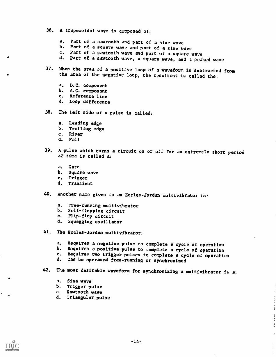
36. A trapezoidal wave is composed of:
a. Part of a sawtooth and part of a sine waveb. Part of a square wave and part of a sine wavec. Part of a sawtooth wave and part of a square waved. Part of a sawtooth wave, a square wave, and a peaked wave
37. When the area of a positive loop of a waveform is subtracted fromthe area of the negative loop, the resultant is called the:
a. D.C. componentb. A.C. componentc. Reference lined. Loop difference
38. The left side of a pulse is called;
a. Leading edgeb. Trailing edgec. Riserd. Fall
39. A pulse which turns a circuit on or off for an extremely short periodcf time is called a:
a. Gateb. Square wavec. Triggerd. Transient
40. Another name given to an Eccles-Jordan multivibrator is:
a. Free-running multivibratorb. Self-flopping circuitc. Flip-flop circuitd. Squegging oscillator
41. The EcclesJordan multivibrator:
a. Requires a negative pulse to complete a cycle of operationb. Requires a positive pulse to complete a cycle of operationc. Requires two trigger pulses to complete a cycle of operationd. Can be operated free-running or synchronized
42. The most desirable waveform for synchronizing a multivibrator i a:
a. Sine waveb. Trigger pulsec. Sawtooth waved. Triangular pulse

43. The cathode coupled multivibrator:
a. Is also known as a one shot multivibratorb. Uses a cathode resistor to maintain one tube always at cutoff,
until it is triggered by an external pulsec. Has one grid returned to the cathoded. Has equal bias voltages on the two cathodes
44. In a plate coupled multivibrator, the approximate frequency ofoperation is determined by:
a. The grid resistorsb. The plate resistorsc. The coupling capacitorsd. The coupling capacitors and the grid resistors
45. When synchronizing a single swing blocking oscillator, it is usuallydesirable to have:
a. The free-running frequency higher than the forced frequency
b. The free-running frequency lower than the forced frequency
c. The free-running frequency the same as the forced frequency
d. None of the above is correct. A blocking oscillator cannot be
synchronized
46. In a multivibrator circuit:
a. A rise in the grid voltage of one tube causes a correspondingincrease in the plate current of the other tube.
b. An increase of current through the load resistor of one tubecauses the grid voltage of the other tube to decrease
c. When current is flowing in one tube, its associated plate coupling
capacitor is charging.d. The cathodes must stay positive with respect to the grids in order
to complete a full cycle of operation
47. The function of a multivibrator is to produce:
a. Triggering pulsesb. Exponential waveforms at the grid
c. Square or rectangular wavesd. Pure sine waves
48. A multivibrator that operates continuously without the aid of an
input signal is called:
a. Astableb. Bistablec. Monostabled. Duostable
-15-

49. A multivibrator where the plates of the tubes are coupled to thegrids of the opposite tube is called:
a. Cathode coupledb. Grid coupledc. Flip flopd. Plate coupled
50. The shock excited oscillator produces a peaked wave rather than asine wave by:
a. Controlling the frequency of the input pulsesb. Use of grid-leak bias -
c. Use of the low "Q" circuit' d. Use of the distributed capacitance
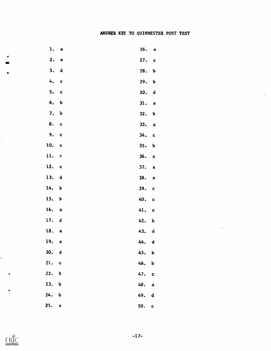
ANSWER KEY TO QUINMESTER POST TEST
1. a 26. a
2. a 27. c
3. d 28. b
4. c 29. b
5. c 30. d
6. b 31. a
7. b 32. b
8. c 33. a
9. c 34.
10. c 35. b
11. c 36.
12. c 37. a
13. d 38. a
14. b 39. c
15. b 40. c
16. a 41. c
17. d 42. b
18. a 43. d
19. a 44. d
20. d 45. b
21. c 46. b
22. b 47. c
23. b 48. a
24. b 49. d
25. a 50. c