EMR’11 Joint Summer School EMR’11 Lausanne … · design Energetic Puzzles (Laplace, France)...
53
EMR’11 Lausanne July 2011 Joint Summer School EMR’11 “Energetic Macroscopic Representation” Prof. Alain BOUSCAYROL L2EP, University Lille1, MEGEVH network, [email protected] Prof. Alfred RUFER, Dr. Philippe BARRADE LEI, Ecole Polytechnique Fédérale de Lausanne, [email protected]
-
Upload
nguyendiep -
Category
Documents
-
view
216 -
download
1
Transcript of EMR’11 Joint Summer School EMR’11 Lausanne … · design Energetic Puzzles (Laplace, France)...

EMR’11 Lausanne July 2011
Joint Summer School EMR’11 “Energetic Macroscopic Representation”
Prof. Alain BOUSCAYROL L2EP, University Lille1, MEGEVH network,
Prof. Alfred RUFER, Dr. Philippe BARRADE LEI, Ecole Polytechnique Fédérale de Lausanne,

EMR’11 Lausanne July 2011
Joint Summer School EMR’11 “Energetic Macroscopic Representation”
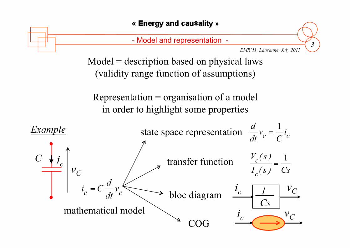
EMR’11, Lausanne, July 2011 3
Model = description based on physical laws (validity range function of assumptions)
Representation = organisation of a model in order to highlight some properties
vC ic
vC ic
Example
vC C ic
mathematical model
state space representation
transfer function
bloc diagram
COG
Cs 1
- Model and representation -

EMR’11, Lausanne, July 2011 4
real system
system model
system representation
- Simulation of a system (1) -
system simulation
model objective
limited validity range
organization
valuable properties
behavior study
prediction
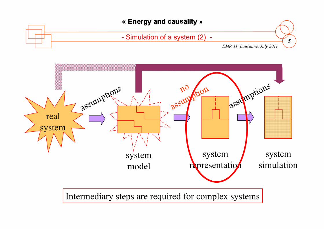
EMR’11, Lausanne, July 2011 5
real system
system model
system representation
system simulation
Intermediary steps are required for complex systems
- Simulation of a system (2) -
Classical way (e.g. Matlab-Simulink©)

EMR’11, Lausanne, July 2011 6
different kinds of objectives
different kinds of modelling
Objectives: • component design/optimization • component control • system analysis (efficiency…) • energy management of the system • ….
Modelling: • structural/functional models • static/dynamic models • causal/ acausal representations • backward/forward simulation • ...
Which model?
[Chan 2010]
- Model objectives -

EMR’11, Lausanne, July 2011 7
A typical example from the domain of electrical engineering
- Functional representations -

EMR’11, Lausanne, July 2011 8
The use of space phasors
Real and Immaginary parts
- Functional representations -

EMR’11, Lausanne, July 2011 9
Rotating Reference frame
Stationary Reference frame
(Phasors Space Vectors)
Some properties depend from the definition of the reference frame!!
- Functional representations -

EMR’11, Lausanne, July 2011 10
Rotating Reference frame
Real and Immaginary parts
- Functional representations -

EMR’11, Lausanne, July 2011 11
A DC current machine fed with a bidirectionnal VSC
- Structural diagrams and interfaces -

EMR’11, Lausanne, July 2011 12
Multidisciplinary studies:
Electrical engineers know in principle how to adapt models (p.u. systems)
Example of calculation of the torque in a synchrounous motor
- Structural diagrams and interfaces -

EMR’11, Lausanne, July 2011 13
Even the behaviour of the mechanical system is not difficult to integrate
- Structural diagrams and interfaces -

EMR’11, Lausanne, July 2011 14
u
i
Physical quantities
i
u
i
« Informations , signals»
Functional representation
(Voltage source)
- From the physical quantity to the signal -
EMR’11, Lausanne, July 2011 15
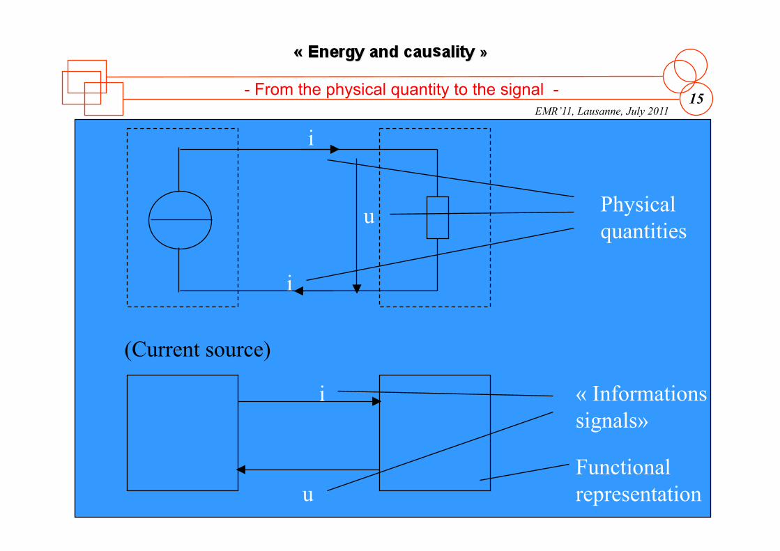
u
i
Physical quantities
i
u
i « Informations , signals»
Functional representation
(Current source)
- From the physical quantity to the signal -

EMR’11, Lausanne, July 2011 16 - The complexity of the interface (physical quantity) -
two DC machines system
PSIM (structural) Matlab-Simulink (functionnal)
machines connected by a unique link (shaft)
machines connected by two links (torque/speed)

EMR’11, Lausanne, July 2011 17
area
knowledge of past evolution
OK in real-time
Principle of causality physical causality is integral
input output
cause effect
t1 t
x
knowledge of future evolution
slope
?
impossible in real-time
- Causality principle -

EMR’11, Lausanne, July 2011 18 - Causality principle -
Example
vC C ic
delay no energy disruption
vC ic
risk of damage
vC ic d dt
For energetic systems physical causality is VITAL

EMR’11, Lausanne, July 2011 19 - The questions about causality -
• Remember: • A state-space quantity (for example X(t) ) represents a given content of stored energy
– Examples • Inductors, capacitors (el. engineering) • Speed or rotational speed of masses (mech.
engineering) • Also position, height with gravity (potential energy) • Ion concentration (chem. engineering)
The problem: dx/dt, the derivation Question : how to chose the dynamic model, in order to avoid the «infinite» values of instantanous power

EMR’11, Lausanne, July 2011 20
- Very simple examples -
No energy storage
Energy storage inside of the inductor
Energy storage inside of the capacitor

EMR’11, Lausanne, July 2011 21 - No energy storage -

EMR’11, Lausanne, July 2011 22 - Energy storage inside of the inductor -
Io: Causal function « A current is injected through the resistor »

EMR’11, Lausanne, July 2011 23
- Energy storage inside of the inductor -
(!) derivation of the state variable

EMR’11, Lausanne, July 2011 24
- Energy storage inside of the capacitor -
Uc: causal function « A Voltage is applied to the terminals of the resistor »

EMR’11, Lausanne, July 2011 25
- Energy storage inside of the capacitor -
(!) derivation of the state variable (!) derivation of the input quantity

EMR’11 Lausanne July 2011
Joint Summer School EMR’11 “Energetic Macroscopic Representation”

EMR’11, Lausanne, July 2011 27
Energy & System
mathematical model
global controls
analysis design
Energetic Puzzles (Laplace, France)
Bond Graph (USA, The Netherlands…)
Power Oriented Graph (Italy)
Signal Flow Diagram (Germany, Japan...)...
1 0
- Comparison of modelling tools -
COG (L2EP-LEEI, France)
EMR (L2EP, France)
causal descriptions
for simulation and control
cascaded control
inversion graphs

EMR’11, Lausanne, July 2011 28 - Graphical modelling tools -
1960 2000 2020 1980
use of Petri Nets
Power Electronics
discrete event systems
Bond Graph
system analysis and design (structural approach)
Mechanical Engineering
Electrical Engineering
USA The Netherlands worldwide
Causal Ordering Graph (COG)
drive control (functional approach)
Electric Drives France
Energetic Macroscopic Representation (EMR)
system control (functional approach)
Electric Systems France Canada
Switzerland Denmark China…
Energetic Systems

EMR’11, Lausanne, July 2011 29
e: effort
f: flow
- Bond Graph -

EMR’11, Lausanne, July 2011 30 - Bond Graph -

EMR’11, Lausanne, July 2011 31 - Bond Graph -

EMR’11, Lausanne, July 2011 32
The principle of causality
- Bond Graph -

EMR’11, Lausanne, July 2011 33 - Bond Graph -

EMR’11, Lausanne, July 2011 34
Schematic representation of a DC motor fed by a power electronic converter
- Bond Graph: example -

EMR’11, Lausanne, July 2011 35
Bond Graphs - Bond Graph (example) -
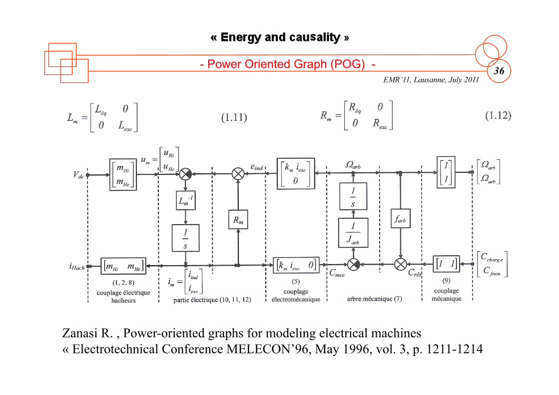
EMR’11, Lausanne, July 2011 36
Zanasi R. , Power-oriented graphs for modeling electrical machines « Electrotechnical Conference MELECON’96, May 1996, vol. 3, p. 1211-1214
- Power Oriented Graph (POG) -

EMR’11, Lausanne, July 2011 37 - Power Oriented Graph (POG) -

EMR’11, Lausanne, July 2011 38
Schönfeld R. , Leitner H.G. Power flow and information flow in motion control systems EPE-PEMC Riga, Sept. 2004
- Power Flow Diagram (PFD) -

EMR’11, Lausanne, July 2011 39 - Power Flow Diagram (PFD) -

EMR’11, Lausanne, July 2011 40
Remember, See the wood before the trees!
Use of GRAPHICAL DESCRIPTIONS for modelling and control of non-elementary systems
System: sub-systems in interactions organised for a common objective
transportation systems renewable energy applications production machines drives in industry process tactile interfaces...
intermediary step for another view of the system
• synthetic description • respect of physical properties • linked to classical modelling
new ways to design, analyse simulate and manage such systems
- Graphical description -

EMR’11, Lausanne, July 2011 41
iei
VDC iHi uHi
voiture
vrame
ufiltre
iHe2 iee2
iHe1 iee1 uHe1
uHe2
ihach
ifiltre
+ CM1
ΩB1 CM2
ΩB2
Fres
- Example of a railway traction system -
iHe1
M s
vrame
Fres
Ftot
kbog
kbog
kbog
kbog
Fbog1
Fbog2
k1 1+τ1s
x CM1
ΩB1
uHe x
CM1
x
k2 1+τ2s
kmcc
iei iee1
x
k2 1+τ2s kmcc
iee2
uHe1
x
x
cHe1
x
x
x
x
uHe2 eee2
eee1
iHe
iHe2
k3 1+τ3s
ihach
k3 1+τ3s
ifiltrre ufiltrre VDC
[K]
cHi [K]
cHe2 [K]
Simplified block diagram causality? action/reaction?
EMR’11, Lausanne, July 2011 42
iei
VDC iHi uHi
voiture
vrame
ufiltre
iHe2 iee2
iHe1 iee1 uHe1
uHe2
ihach
ifiltre
+ CM1
ΩB1 CM2
ΩB2
Fres
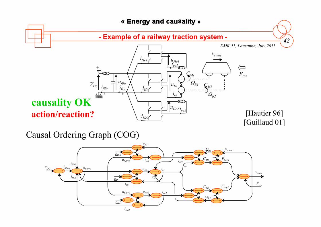
- Example of a railway traction system -
Causal Ordering Graph (COG)
ufiltrre
vrame
Fres
CM1
ΩB1
eei
iee1 cHe1
iHe2 ifiltrre ufiltrre VDC
cHi uHi iei
uHi
iee1 Fbog1
vrame
CM2
ΩB2
Fbog2
ufiltrre uHe2 cHe2
iee2
iee1
iHe2
iHi
iHe1
[Hautier 96] [Guillaud 01]
causality OK action/reaction?

EMR’11, Lausanne, July 2011 43
iei
VDC iHi uHi
voiture
vrame
ufiltre
iHe2 iee2
iHe1 iee1 uHe1
uHe2
ihach
ifiltre
+ CM1
ΩB1 CM2
ΩB2
Fres
- Example of a railway traction system -
Bond Graph (BG)
[Paynter 61] [Dauphin 99]
R : Rind2
1
vrame
Fres
CM1
ΩB1 eei1 cHe1
ifiltre ufiltre
Se : VDC cHi
uHi iei
uHe1 iee1
Fbog1 vrame
iHi
iHe1 1
VDC 0
R : Rf
ifiltre ufiltre
I : Lf C : Cf
MTF 1
MTF ufiltre R : Rind1
I : Lind1
1
I : Lind2
MGY
iei
eei2 iei
TF
1I : M vrame Charge
CM2
ΩB2 MGY TF
Fbog2 vrame
1
R : Rex1
I : Lex1
1cHe1 uHe2 iee2 MTF 1
R : Rex1
I : Lex1
iHe2 ufiltre
physical causality? action/reaction OK

EMR’11, Lausanne, July 2011 44
iei
VDC iHi uHi
voiture
vrame
ufiltre
iHe2 iee2
iHe1 iee1 uHe1
uHe2
ihach
ifiltre
+ CM1
ΩB1 CM2
ΩB2
Fres
- Example of a railway traction system -
Energetic Macroscopic Representation (EMR)
[Bouscayrol 00] [Bouscayrol 05]
rail
filtre
mise en // enroulements
hacheurs
conv. EM
bogie
couplage
rame
environnement
Ftot vrame
iHe1
M2
eee2 iee2
VDC ihach
uHe2 iee2 He2
CM2 ΩB2 B2
FB2
vrame
vrame
Fres
cHe2
SM SE
ufiltre iHi
uHi iei Hi
cHi
iei eei
M1 CM1 ΩB1 B2
FB1 vrame
iei eei1 iei eei2
ufiltre
ifiltre
ufiltre iHe2
eee1 iee1 uHe1
iee1 He1
cHe1
ufiltre
mise en série
physical causality OK action/reaction OK

EMR’11 Lausanne July 2011
Joint Summer School EMR’11 “Energetic Macroscopic Representation”

EMR’11, Lausanne, July 2011 46
- -
Multi-physical system
Real-time control
Systemic approach
Dynamical modeling Causal modeling
Energy management Energetic approach Causal modeling
System control Functional description
Moreover a graphical description could be a valuable intermediary step for such complex systems
- Which model for EV/HEV control? -
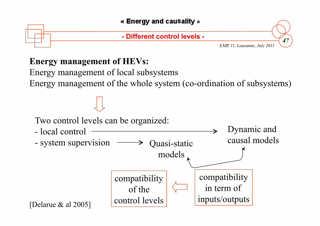
EMR’11, Lausanne, July 2011 47 - Different control levels -
Energy management of HEVs: Energy management of local subsystems Energy management of the whole system (co-ordination of subsystems)
Two control levels can be organized: - local control - system supervision
Dynamic and causal models Quasi-static
models
compatibility in term of
inputs/outputs
compatibility of the
control levels [Delarue & al 2005]

EMR’11, Lausanne, July 2011 48 - Different control levels (example) -
BAT
ICE
VSI EM
Fuel Parallel HEV Trans.
fast subsystem controls
EM control
ICE control
Trans control
Energy management (supervision/strategy)
driver request
slow system supervision

EMR’11, Lausanne, July 2011 49 - Local control -
EM control
ICE control
Trans control
Local energy management: must take into account power flows in all parts of subsystems
Classical controls of subsystems: required dynamic and energetic models to manage power flows in real-time

EMR’11, Lausanne, July 2011 50
- Energy management methods -
[Salmasi 2007]
Energy management (supervision/strategy)
driver request
Rule-based
deterministic rule-based
fuzzy rule-based
state machine / power follower/ thermostat control…
predictive / adpative / conventional…
Optimization based
global optimization
real-time optimization
Dynamic programming / stochastic DP / Game theory / Optimal control….
Robust control / Model predictive / decoupling control / l control…

EMR’11 Lausanne July 2011
Joint Summer School EMR’11 “Energetic Macroscopic Representation”
system = subsystems in interaction best performances require a systemic approach
energy = respect of the physical causality energy management requires a causal approach
control -> inversion of a causal model of the system in order to respect its energy properties
graphical description = model organization useful intermediary step
Remember, follow a disciplined procedure!
EMR’11, Lausanne, July 2011 52
- References -
P. J. Barre, & al, "Inversion-based control of electromechanical systems using causal graphical descriptions", IEEE-IECON'06, Paris, November 2006.
A. Bouscayrol, & al. "Multimachine Multiconverter System: application for electromechanical drives", European Physics Journal - Applied Physics, vol. 10, no. 2, May 2000, pp. 131-147 (common paper GREEN Nancy, L2EP Lille and LEEI Toulouse, according to the SMM project of the GDR-SDSE).
A. Bouscayrol, G. Dauphin-Tanguy, R Schoenfeld, A. Pennamen, X. Guillaud, G.-H. Geitner, "Different energetic descriptions for electromechanical systems", EPE'05, Dresden (Germany), September 2005. (common paper of L2EP, LAGIS and University Dresden).
C.C. Chan, “The state of the art of electric, hybrid, and fuel cell vehicles", Proceedings of the IEEE, Vol. 95, No.4, pp. 704-718, April 2007.
C.C. Chan, A. Bouscayrol, K. Chen, "Philosophy of Engineering and Modelling of Electric Drives”, International Conference on Electrical, Keynote, October 2008, Wuhan (China)
C. C. Chan, A. Bouscayrol, K. Chen, “Electric, Hybrid and Fuel Cell Vehicles: Architectures and Modeling", IEEE transactions on Vehicular Technology, vol. 59, no. 2, February 2010, pp. 589-598 (common paper of L2EP Lille and Honk-Kong University).
G. H. Geitner, "Power Flow Diagrams Using a Bond graph Library under Simulink", IEEE-IECON'06, Paris, November 2006.
J. P. Hautier, P. J. Barre, "The causal ordering graph - A tool for modelling and control law synthesis", Studies in Informatics and Control Journal, vol. 13, no. 4, December 2004, pp. 265-283.
H. Paynter, "Analysis and design of engineering systems", MIT Press, 1961.
F. R. Salmasi, "Control strategies for Hybrid Electric Vehicles: evolution, classification, comparison and future trends", IEEE Trans. on Vehicular Technology, September 2007, Vol. 56, No. 3, pp. 2393-2404
R. Zanasi, R. Morselli, "Modeling of Automotive Control Systems Using Power Oriented Graphs", IEEE-IECON'06, Paris, November 2006.

EMR’11, Lausanne, July 2011 53
Interaction principle Each action induces a reaction
action
reaction
S2 S2
Power exchanged by S1and S2 = action x réaction
power
- Interaction principle -
Example
battery load
Vbat Vbat
iload
load battery Vbat
iload
P=Vbat iload