Emission Factor Documentation for AP-42 Electroplating ... · PDF fileEmission Factor...
250
Emission Factor Documentation for AP-42 Section 12.20 Electroplating Final Report For U. S. Environmental Protection Agency Office of Air Quality Planning and Standards Emission Factor and Inventory Group EPA Contract 68-D2-0159 Work Assignment No. III-01 MRI Project No. 4603-01 July 1996
Transcript of Emission Factor Documentation for AP-42 Electroplating ... · PDF fileEmission Factor...

Emission Factor Documentation for AP-42Section 12.20
Electroplating
Final Report
For U. S. Environmental Protection AgencyOffice of Air Quality Planning and Standards
Emission Factor and Inventory Group
EPA Contract 68-D2-0159Work Assignment No. III-01
MRI Project No. 4603-01
July 1996
Emission Factor Documentation for AP-42Section 12.20
Electroplating
Final Report
For U. S. Environmental Protection AgencyOffice of Air Quality Planning and Standards
Emission Factor and Inventory GroupResearch Triangle Park, NC 27711
Attn: Mr. Ron Myers (MD-14)
EPA Contract 68-D2-0159Work Assignment No. III-01
MRI Project No. 4603-01
July 1996

ii
NOTICE
The information in this document has been funded wholly or in part by the United States EnvironmentalProtection Agency under Contract No. 68-D2-0159 to Midwest Research Institute. It has been reviewed bythe Office of Air Quality Planning and Standards, U. S. Environmental Protection Agency, and has beenapproved for publication. Mention of trade names or commercial products does not constitute endorsementor recommendation for use.

iii
PREFACE
This report was prepared by Midwest Research Institute (MRI) for the Office of Air Quality
Planning and Standards (OAQPS), U. S. Environmental Protection Agency (EPA), under Contract
No. 68-D2-0159, Work Assignment No. III-01. Mr. Ron Myers was the requester of the work.
Approved for:
MIDWEST RESEARCH INSTITUTE
Roy Neulicht
Program Manager
Environmental Engineering Department
Jeff Shular
Director, Environmental Engineering
Department
July 1996

iv
CONTENTS
Page
LIST OF FIGURES . . . . . . . . . . . . . . . . . . . . . . . . . . . . . . . . . . . . . . . . . . . . . . . . . . . . . . . . . . . viiiLIST OF TABLES . . . . . . . . . . . . . . . . . . . . . . . . . . . . . . . . . . . . . . . . . . . . . . . . . . . . . . . . . . . ix
1. INTRODUCTION . . . . . . . . . . . . . . . . . . . . . . . . . . . . . . . . . . . . . . . . . . . . . . . . . . . . . . . . . 1-12. INDUSTRY DESCRIPTION . . . . . . . . . . . . . . . . . . . . . . . . . . . . . . . . . . . . . . . . . . . . . . . . . 2-1
2.1 INDUSTRY CHARACTERIZATION . . . . . . . . . . . . . . . . . . . . . . . . . . . . . . . . . . . . . 2-12.2 PROCESS DESCRIPTION . . . . . . . . . . . . . . . . . . . . . . . . . . . . . . . . . . . . . . . . . . . . . 2-1
2.2.1 Chromium Electroplating . . . . . . . . . . . . . . . . . . . . . . . . . . . . . . . . . . . . . . . . . 2-22.2.2 Other Types of Electroplating . . . . . . . . . . . . . . . . . . . . . . . . . . . . . . . . . . . . . . 2-10
3. GENERAL DATA REVIEW AND ANALYSIS PROCEDURES . . . . . . . . . . . . . . . . . . . . . 3-13.1 LITERATURE SEARCH AND SCREENING . . . . . . . . . . . . . . . . . . . . . . . . . . . . . . . 3-13.2 DATA QUALITY RATING SYSTEM . . . . . . . . . . . . . . . . . . . . . . . . . . . . . . . . . . . . . 3-13.3 EMISSION FACTOR QUALITY RATING SYSTEM . . . . . . . . . . . . . . . . . . . . . . . . . 3-33.4 EMISSION TEST METHODS FOR CHROMIUM ELECTROPLATING AND
CHROMIC ACID ANODIZING . . . . . . . . . . . . . . . . . . . . . . . . . . . . . . . . . . . . . . . . . 3-33.5 FACTORS AFFECTING CHROMIUM EMISSIONS FROM ELECTROPLATING
AND ANODIZING . . . . . . . . . . . . . . . . . . . . . . . . . . . . . . . . . . . . . . . . . . . . . . . . . . . 3-53.6 EMISSION FACTOR UNITS FOR ELECTROPLATING AND CHROMIC ACID
ANODIZING . . . . . . . . . . . . . . . . . . . . . . . . . . . . . . . . . . . . . . . . . . . . . . . . . . . . . . . . 3-83.6.1 Electroplating Emission Factor Units . . . . . . . . . . . . . . . . . . . . . . . . . . . . . . . . 3-83.6.2 Chromic Acid Anodizing Emission Factor Units . . . . . . . . . . . . . . . . . . . . . . . . 3-8
4. AP-42 SECTION DEVELOPMENT . . . . . . . . . . . . . . . . . . . . . . . . . . . . . . . . . . . . . . . . . . . 4-14.1 REVIEW OF SPECIFIC DATA SETS . . . . . . . . . . . . . . . . . . . . . . . . . . . . . . . . . . . . . 4-1
4.1.1 Reference 1 . . . . . . . . . . . . . . . . . . . . . . . . . . . . . . . . . . . . . . . . . . . . . . . . . . . . 4-14.1.2 Reference 2 . . . . . . . . . . . . . . . . . . . . . . . . . . . . . . . . . . . . . . . . . . . . . . . . . . . . 4-14.1.3 Reference 3 . . . . . . . . . . . . . . . . . . . . . . . . . . . . . . . . . . . . . . . . . . . . . . . . . . . . 4-24.1.4 Reference 4 . . . . . . . . . . . . . . . . . . . . . . . . . . . . . . . . . . . . . . . . . . . . . . . . . . . . 4-34.1.5 Reference 5 . . . . . . . . . . . . . . . . . . . . . . . . . . . . . . . . . . . . . . . . . . . . . . . . . . . . 4-44.1.6 Reference 6 . . . . . . . . . . . . . . . . . . . . . . . . . . . . . . . . . . . . . . . . . . . . . . . . . . . . 4-44.1.7 Reference 7 . . . . . . . . . . . . . . . . . . . . . . . . . . . . . . . . . . . . . . . . . . . . . . . . . . . . 4-64.1.8 Reference 8 . . . . . . . . . . . . . . . . . . . . . . . . . . . . . . . . . . . . . . . . . . . . . . . . . . . . 4-74.1.9 Reference 9 . . . . . . . . . . . . . . . . . . . . . . . . . . . . . . . . . . . . . . . . . . . . . . . . . . . . 4-74.1.10 Reference 10 . . . . . . . . . . . . . . . . . . . . . . . . . . . . . . . . . . . . . . . . . . . . . . . . . . . 4-84.1.11 Reference 11 . . . . . . . . . . . . . . . . . . . . . . . . . . . . . . . . . . . . . . . . . . . . . . . . . . . 4-94.1.12 Reference 12 . . . . . . . . . . . . . . . . . . . . . . . . . . . . . . . . . . . . . . . . . . . . . . . . . . . 4-104.1.13 Reference 13 . . . . . . . . . . . . . . . . . . . . . . . . . . . . . . . . . . . . . . . . . . . . . . . . . . . 4-114.1.14 Reference 14 . . . . . . . . . . . . . . . . . . . . . . . . . . . . . . . . . . . . . . . . . . . . . . . . . . . 4-124.1.15 Reference 15 . . . . . . . . . . . . . . . . . . . . . . . . . . . . . . . . . . . . . . . . . . . . . . . . . . . 4-134.1.16 Reference 16 . . . . . . . . . . . . . . . . . . . . . . . . . . . . . . . . . . . . . . . . . . . . . . . . . . . 4-134.1.17 Reference 17 . . . . . . . . . . . . . . . . . . . . . . . . . . . . . . . . . . . . . . . . . . . . . . . . . . . 4-154.1.18 Reference 18 . . . . . . . . . . . . . . . . . . . . . . . . . . . . . . . . . . . . . . . . . . . . . . . . . . . 4-154.1.19 Reference 19 . . . . . . . . . . . . . . . . . . . . . . . . . . . . . . . . . . . . . . . . . . . . . . . . . . . 4-164.1.20 Reference 20 . . . . . . . . . . . . . . . . . . . . . . . . . . . . . . . . . . . . . . . . . . . . . . . . . . . 4-174.1.21 Reference 21 . . . . . . . . . . . . . . . . . . . . . . . . . . . . . . . . . . . . . . . . . . . . . . . . . . . 4-18

TABLE OF CONTENTS (continued)
Page
v
4.1.22 Reference 22 . . . . . . . . . . . . . . . . . . . . . . . . . . . . . . . . . . . . . . . . . . . . . . . . . . . 4-194.1.23 Reference 23 . . . . . . . . . . . . . . . . . . . . . . . . . . . . . . . . . . . . . . . . . . . . . . . . . . . 4-194.1.24 Reference 24 . . . . . . . . . . . . . . . . . . . . . . . . . . . . . . . . . . . . . . . . . . . . . . . . . . . 4-194.1.25 Reference 25 . . . . . . . . . . . . . . . . . . . . . . . . . . . . . . . . . . . . . . . . . . . . . . . . . . . 4-204.1.26 Reference 26 . . . . . . . . . . . . . . . . . . . . . . . . . . . . . . . . . . . . . . . . . . . . . . . . . . . 4-204.1.27 Reference 27 . . . . . . . . . . . . . . . . . . . . . . . . . . . . . . . . . . . . . . . . . . . . . . . . . . . 4-214.1.28 Reference 28 . . . . . . . . . . . . . . . . . . . . . . . . . . . . . . . . . . . . . . . . . . . . . . . . . . . 4-214.1.29 Reference 29 . . . . . . . . . . . . . . . . . . . . . . . . . . . . . . . . . . . . . . . . . . . . . . . . . . . 4-214.1.30 Reference 30 . . . . . . . . . . . . . . . . . . . . . . . . . . . . . . . . . . . . . . . . . . . . . . . . . . . 4-224.1.31 Reference 31 . . . . . . . . . . . . . . . . . . . . . . . . . . . . . . . . . . . . . . . . . . . . . . . . . . . 4-224.1.32 Reference 33 . . . . . . . . . . . . . . . . . . . . . . . . . . . . . . . . . . . . . . . . . . . . . . . . . . . 4-234.1.33 Reference 58 . . . . . . . . . . . . . . . . . . . . . . . . . . . . . . . . . . . . . . . . . . . . . . . . . . . 4-234.1.34 Reference 59 . . . . . . . . . . . . . . . . . . . . . . . . . . . . . . . . . . . . . . . . . . . . . . . . . . . 4-244.1.35 Reference 62 . . . . . . . . . . . . . . . . . . . . . . . . . . . . . . . . . . . . . . . . . . . . . . . . . . . 4-244.1.36 Reference 63 . . . . . . . . . . . . . . . . . . . . . . . . . . . . . . . . . . . . . . . . . . . . . . . . . . . 4-254.1.37 Reference 66 . . . . . . . . . . . . . . . . . . . . . . . . . . . . . . . . . . . . . . . . . . . . . . . . . . . 4-254.1.38 Reference 67 . . . . . . . . . . . . . . . . . . . . . . . . . . . . . . . . . . . . . . . . . . . . . . . . . . . 4-254.1.39 Reference 71 . . . . . . . . . . . . . . . . . . . . . . . . . . . . . . . . . . . . . . . . . . . . . . . . . . . 4-264.1.40 Reference 74 . . . . . . . . . . . . . . . . . . . . . . . . . . . . . . . . . . . . . . . . . . . . . . . . . . . 4-274.1.41 Reference 75 . . . . . . . . . . . . . . . . . . . . . . . . . . . . . . . . . . . . . . . . . . . . . . . . . . . 4-274.1.42 Reference 77 . . . . . . . . . . . . . . . . . . . . . . . . . . . . . . . . . . . . . . . . . . . . . . . . . . . 4-274.1.43 Reference 78 . . . . . . . . . . . . . . . . . . . . . . . . . . . . . . . . . . . . . . . . . . . . . . . . . . . 4-284.1.44 Reference 81 . . . . . . . . . . . . . . . . . . . . . . . . . . . . . . . . . . . . . . . . . . . . . . . . . . . 4-284.1.45 Reference 83 . . . . . . . . . . . . . . . . . . . . . . . . . . . . . . . . . . . . . . . . . . . . . . . . . . . 4-294.1.46 Reference 84 . . . . . . . . . . . . . . . . . . . . . . . . . . . . . . . . . . . . . . . . . . . . . . . . . . . 4-294.1.47 Reference 85 . . . . . . . . . . . . . . . . . . . . . . . . . . . . . . . . . . . . . . . . . . . . . . . . . . . 4-294.1.48 Reference 86 . . . . . . . . . . . . . . . . . . . . . . . . . . . . . . . . . . . . . . . . . . . . . . . . . . . 4-304.1.49 Reference 88 . . . . . . . . . . . . . . . . . . . . . . . . . . . . . . . . . . . . . . . . . . . . . . . . . . . 4-304.1.50 Reference 89 . . . . . . . . . . . . . . . . . . . . . . . . . . . . . . . . . . . . . . . . . . . . . . . . . . . 4-314.1.51 Reference 90 . . . . . . . . . . . . . . . . . . . . . . . . . . . . . . . . . . . . . . . . . . . . . . . . . . . 4-314.1.52 Reference 93 . . . . . . . . . . . . . . . . . . . . . . . . . . . . . . . . . . . . . . . . . . . . . . . . . . . 4-314.1.53 Reference 94 . . . . . . . . . . . . . . . . . . . . . . . . . . . . . . . . . . . . . . . . . . . . . . . . . . . 4-324.1.54 Reference 95 . . . . . . . . . . . . . . . . . . . . . . . . . . . . . . . . . . . . . . . . . . . . . . . . . . . 4-324.1.55 Reference 98 . . . . . . . . . . . . . . . . . . . . . . . . . . . . . . . . . . . . . . . . . . . . . . . . . . . 4-33
4.2 DEVELOPMENT OF CANDIDATE EMISSION FACTORS . . . . . . . . . . . . . . . . . . . 4-344.2.1 General Procedures . . . . . . . . . . . . . . . . . . . . . . . . . . . . . . . . . . . . . . . . . . . . . . 4-344.2.2 Hard Chromium Electroplating . . . . . . . . . . . . . . . . . . . . . . . . . . . . . . . . . . . . . 4-354.2.3 Decorative Chromium Electroplating . . . . . . . . . . . . . . . . . . . . . . . . . . . . . . . . . 4-364.2.4 Chromic Acid Anodizing . . . . . . . . . . . . . . . . . . . . . . . . . . . . . . . . . . . . . . . . . . 4-374.2.5 Total PM Emissions From Chromium Electroplating and Chromic
Acid Anodizing . . . . . . . . . . . . . . . . . . . . . . . . . . . . . . . . . . . . . . . . . . . . . . . . . 4-384.2.6 Electroplating of Other (Nonchromium) Metals . . . . . . . . . . . . . . . . . . . . . . . . . 4-394.2.7 Statistical Analysis of Emission Factor Data . . . . . . . . . . . . . . . . . . . . . . . . . . . 4-39

TABLE OF CONTENTS (continued)
Page
vi
4.3 ESTIMATES OF EMISSIONS FROM OTHER TYPES OF ELECTROPLATING . . . 4-394.3.1 Uncontrolled Emissions From Nonchromium Electroplating . . . . . . . . . . . . . . . . 4-394.3.2 Controlled Emissions From Nonchromium Electroplating . . . . . . . . . . . . . . . . . 4-404.3.3 Emissions From Air Sparging and Electroless Plating . . . . . . . . . . . . . . . . . . . . 4-414.3.4 Example Calculations . . . . . . . . . . . . . . . . . . . . . . . . . . . . . . . . . . . . . . . . . . . . 4-42
5. PROPOSED AP-42 SECTION 12.20 . . . . . . . . . . . . . . . . . . . . . . . . . . . . . . . . . . . . . . . . . . 5-1
vii
LIST OF FIGURES
Figure Page
2-1 Flow diagram for a typical hard chromium plating process . . . . . . . . . . . . . . . . . . 2-132-2 Flow diagram for decorative chromium plating on a metal substrate . . . . . . . . . . . 2-142-3 Flow diagram for a typical chromic acid anodizing process . . . . . . . . . . . . . . . . . 2-15

viii
LIST OF TABLES
Table Page
4-1. REFERENCES NOT USED FOR EMISSION FACTOR DEVELOPMENT . . . . . . 4-444-2. SUMMARY OF PARAMETERS AND RESULTS OF EMISSION TESTS FOR
REFERENCE 1 . . . . . . . . . . . . . . . . . . . . . . . . . . . . . . . . . . . . . . . . . . . . . . . . . . . . 4-464-3. SUMMARY OF PARAMETERS AND RESULTS OF EMISSION TESTS FOR
REFERENCE 2 . . . . . . . . . . . . . . . . . . . . . . . . . . . . . . . . . . . . . . . . . . . . . . . . . . . . 4-474-4. SUMMARY OF PARAMETERS AND RESULTS OF EMISSION TESTS FOR
REFERENCE 3 . . . . . . . . . . . . . . . . . . . . . . . . . . . . . . . . . . . . . . . . . . . . . . . . . . . . 4-484-5. SUMMARY OF PARAMETERS AND RESULTS OF EMISSION TESTS FOR
REFERENCE 4 . . . . . . . . . . . . . . . . . . . . . . . . . . . . . . . . . . . . . . . . . . . . . . . . . . . . 4-494-6. SUMMARY OF PARAMETERS AND RESULTS OF EMISSION TESTS FOR
REFERENCE 5 . . . . . . . . . . . . . . . . . . . . . . . . . . . . . . . . . . . . . . . . . . . . . . . . . . . . 4-504-7. SUMMARY OF PARAMETERS AND RESULTS OF EMISSION TESTS FOR
REFERENCE 6 . . . . . . . . . . . . . . . . . . . . . . . . . . . . . . . . . . . . . . . . . . . . . . . . . . . . 4-514-8. SUMMARY OF PARAMETERS AND RESULTS OF EMISSION TESTS FOR
REFERENCE 7 . . . . . . . . . . . . . . . . . . . . . . . . . . . . . . . . . . . . . . . . . . . . . . . . . . . . 4-524-9. SUMMARY OF PARAMETERS AND RESULTS OF EMISSION TESTS FOR
REFERENCE 8 . . . . . . . . . . . . . . . . . . . . . . . . . . . . . . . . . . . . . . . . . . . . . . . . . . . . 4-544-10. SUMMARY OF PARAMETERS AND RESULTS OF EMISSION TESTS FOR
REFERENCE 9 . . . . . . . . . . . . . . . . . . . . . . . . . . . . . . . . . . . . . . . . . . . . . . . . . . . . 4-554-11. SUMMARY OF PARAMETERS AND RESULTS OF EMISSION TESTS FOR
REFERENCE 10 . . . . . . . . . . . . . . . . . . . . . . . . . . . . . . . . . . . . . . . . . . . . . . . . . . . 4-564-12. AVERAGE OPERATING PARAMETERS MONITORED DURING EACH
EMISSIONS TEST RUN . . . . . . . . . . . . . . . . . . . . . . . . . . . . . . . . . . . . . . . . . . . . . 4-574-13. SUMMARY OF PARAMETERS AND RESULTS OF EMISSION TESTS FOR
REFERENCE 11 . . . . . . . . . . . . . . . . . . . . . . . . . . . . . . . . . . . . . . . . . . . . . . . . . . . 4-584-14. DIMENSIONS AND OPERATING PARAMETERS FOR THE SEVEN HARD
CHROMIUM PLATING TANKS FOR REFERENCE 12 . . . . . . . . . . . . . . . . . . . . 4-594-15. SUMMARY OF PARAMETERS AND RESULTS OF EMISSION TESTS FOR
REFERENCE 12 . . . . . . . . . . . . . . . . . . . . . . . . . . . . . . . . . . . . . . . . . . . . . . . . . . . 4-604-16. SUMMARY OF PARAMETERS AND RESULTS OF EMISSION TESTS FOR
REFERENCE 13 . . . . . . . . . . . . . . . . . . . . . . . . . . . . . . . . . . . . . . . . . . . . . . . . . . . 4-614-17. SUMMARY OF PARAMETERS AND RESULTS OF EMISSION TESTS FOR
REFERENCE 14 . . . . . . . . . . . . . . . . . . . . . . . . . . . . . . . . . . . . . . . . . . . . . . . . . . . 4-624-18. SUMMARY OF PARAMETERS AND RESULTS OF EMISSION TESTS FOR
REFERENCE 15 . . . . . . . . . . . . . . . . . . . . . . . . . . . . . . . . . . . . . . . . . . . . . . . . . . . 4-634-19. SUMMARY OF PARAMETERS AND RESULTS OF EMISSION TESTS FOR
REFERENCE 16 . . . . . . . . . . . . . . . . . . . . . . . . . . . . . . . . . . . . . . . . . . . . . . . . . . . 4-644-20. SUMMARY OF PARAMETERS AND RESULTS OF EMISSION TESTS FOR
REFERENCE 17 . . . . . . . . . . . . . . . . . . . . . . . . . . . . . . . . . . . . . . . . . . . . . . . . . . . 4-654-21. SUMMARY OF PARAMETERS AND RESULTS OF EMISSION TESTS FOR
REFERENCE 19 . . . . . . . . . . . . . . . . . . . . . . . . . . . . . . . . . . . . . . . . . . . . . . . . . . . 4-664-22. SUMMARY OF PARAMETERS AND RESULTS OF EMISSION TESTS FOR
REFERENCE 20 . . . . . . . . . . . . . . . . . . . . . . . . . . . . . . . . . . . . . . . . . . . . . . . . . . . 4-674-23. SUMMARY OF PARAMETERS AND RESULTS OF EMISSION TESTS FOR

LIST OF TABLES (continued)
Table Page
ix
REFERENCE 21 . . . . . . . . . . . . . . . . . . . . . . . . . . . . . . . . . . . . . . . . . . . . . . . . . . . 4-684-24. SUMMARY OF PARAMETERS AND RESULTS OF EMISSION TESTS FOR
REFERENCE 22 . . . . . . . . . . . . . . . . . . . . . . . . . . . . . . . . . . . . . . . . . . . . . . . . . . . 4-694-25. SUMMARY OF PARAMETERS AND RESULTS OF EMISSION TESTS FOR
REFERENCE 23 . . . . . . . . . . . . . . . . . . . . . . . . . . . . . . . . . . . . . . . . . . . . . . . . . . . 4-704-26. SUMMARY OF PARAMETERS AND RESULTS OF EMISSION TESTS FOR
REFERENCE 24 . . . . . . . . . . . . . . . . . . . . . . . . . . . . . . . . . . . . . . . . . . . . . . . . . . . 4-714-27. SUMMARY OF PARAMETERS AND RESULTS OF EMISSION TESTS FOR
REFERENCE 25 . . . . . . . . . . . . . . . . . . . . . . . . . . . . . . . . . . . . . . . . . . . . . . . . . . . 4-724-28. SUMMARY OF PARAMETERS AND RESULTS OF EMISSION TESTS FOR
REFERENCE 26 . . . . . . . . . . . . . . . . . . . . . . . . . . . . . . . . . . . . . . . . . . . . . . . . . . . 4-744-29. SUMMARY OF PARAMETERS AND RESULTS OF EMISSION TESTS FOR
REFERENCE 27 . . . . . . . . . . . . . . . . . . . . . . . . . . . . . . . . . . . . . . . . . . . . . . . . . . . 4-764-30. SUMMARY OF PARAMETERS AND RESULTS OF EMISSION TESTS FOR
REFERENCE 28 . . . . . . . . . . . . . . . . . . . . . . . . . . . . . . . . . . . . . . . . . . . . . . . . . . . 4-784-31. SUMMARY OF PARAMETERS AND RESULTS OF EMISSION TESTS FOR
REFERENCE 29 . . . . . . . . . . . . . . . . . . . . . . . . . . . . . . . . . . . . . . . . . . . . . . . . . . . 4-804-32. SUMMARY OF PARAMETERS AND RESULTS OF EMISSION TESTS FOR
REFERENCE 30 . . . . . . . . . . . . . . . . . . . . . . . . . . . . . . . . . . . . . . . . . . . . . . . . . . . 4-814-33. SUMMARY OF PARAMETERS AND RESULTS OF EMISSION TESTS FOR
REFERENCE 31 . . . . . . . . . . . . . . . . . . . . . . . . . . . . . . . . . . . . . . . . . . . . . . . . . . . 4-834-34. SUMMARY OF PARAMETERS AND RESULTS OF EMISSION TESTS FOR
REFERENCE 33 . . . . . . . . . . . . . . . . . . . . . . . . . . . . . . . . . . . . . . . . . . . . . . . . . . . 4-844-35. SUMMARY OF PARAMETERS AND RESULTS OF EMISSION TESTS FOR
REFERENCE 58 . . . . . . . . . . . . . . . . . . . . . . . . . . . . . . . . . . . . . . . . . . . . . . . . . . . 4-854-36. SUMMARY OF PARAMETERS AND RESULTS OF EMISSION TESTS FOR
REFERENCE 59 . . . . . . . . . . . . . . . . . . . . . . . . . . . . . . . . . . . . . . . . . . . . . . . . . . . 4-864-37. SUMMARY OF PARAMETERS AND RESULTS OF EMISSION TESTS FOR
REFERENCE 62 . . . . . . . . . . . . . . . . . . . . . . . . . . . . . . . . . . . . . . . . . . . . . . . . . . . 4-874-38. SUMMARY OF PARAMETERS AND RESULTS OF EMISSION TESTS FOR
REFERENCE 63 . . . . . . . . . . . . . . . . . . . . . . . . . . . . . . . . . . . . . . . . . . . . . . . . . . . 4-884-39. SUMMARY OF PARAMETERS AND RESULTS OF EMISSION TESTS FOR
REFERENCE 66 . . . . . . . . . . . . . . . . . . . . . . . . . . . . . . . . . . . . . . . . . . . . . . . . . . . 4-904-40. SUMMARY OF PARAMETERS AND RESULTS OF EMISSION TESTS FOR
REFERENCE 67 . . . . . . . . . . . . . . . . . . . . . . . . . . . . . . . . . . . . . . . . . . . . . . . . . . . 4-914-41. SUMMARY OF PARAMETERS AND RESULTS OF EMISSION TESTS FOR
REFERENCE 71 . . . . . . . . . . . . . . . . . . . . . . . . . . . . . . . . . . . . . . . . . . . . . . . . . . . 4-944-42. SUMMARY OF PARAMETERS AND RESULTS OF EMISSION TESTS FOR
REFERENCE 74 . . . . . . . . . . . . . . . . . . . . . . . . . . . . . . . . . . . . . . . . . . . . . . . . . . . 4-954-43. SUMMARY OF PARAMETERS AND RESULTS OF EMISSION TESTS FOR
REFERENCE 75 . . . . . . . . . . . . . . . . . . . . . . . . . . . . . . . . . . . . . . . . . . . . . . . . . . . 4-964-44. SUMMARY OF PARAMETERS AND RESULTS OF EMISSION TESTS FOR
REFERENCE 77 . . . . . . . . . . . . . . . . . . . . . . . . . . . . . . . . . . . . . . . . . . . . . . . . . . . 4-974-45. SUMMARY OF PARAMETERS AND RESULTS OF EMISSION TESTS FOR

LIST OF TABLES (continued)
Table Page
x
REFERENCE 78 . . . . . . . . . . . . . . . . . . . . . . . . . . . . . . . . . . . . . . . . . . . . . . . . . . . 4-98
LIST OF TABLES (continued)
Table Page
xi
4-46. SUMMARY OF PARAMETERS AND RESULTS OF EMISSION TESTS FORREFERENCE 81 . . . . . . . . . . . . . . . . . . . . . . . . . . . . . . . . . . . . . . . . . . . . . . . . . . . 4-99
4-47. SUMMARY OF PARAMETERS AND RESULTS OF EMISSION TESTS FORREFERENCE 83 . . . . . . . . . . . . . . . . . . . . . . . . . . . . . . . . . . . . . . . . . . . . . . . . . . . 4-100
4-48. SUMMARY OF PARAMETERS AND RESULTS OF EMISSION TESTS FORREFERENCE 84 . . . . . . . . . . . . . . . . . . . . . . . . . . . . . . . . . . . . . . . . . . . . . . . . . . . 4-101
4-49. SUMMARY OF PARAMETERS AND RESULTS OF EMISSION TESTS FORREFERENCE 85 . . . . . . . . . . . . . . . . . . . . . . . . . . . . . . . . . . . . . . . . . . . . . . . . . . . 4-102
4-50. SUMMARY OF PARAMETERS AND RESULTS OF EMISSION TESTS FORREFERENCE 86 . . . . . . . . . . . . . . . . . . . . . . . . . . . . . . . . . . . . . . . . . . . . . . . . . . . 4-103
4-51. SUMMARY OF PARAMETERS AND RESULTS OF EMISSION TESTS FORREFERENCE 88 . . . . . . . . . . . . . . . . . . . . . . . . . . . . . . . . . . . . . . . . . . . . . . . . . . . 4-104
4-52. SUMMARY OF PARAMETERS AND RESULTS OF EMISSION TESTS FORREFERENCE 89 . . . . . . . . . . . . . . . . . . . . . . . . . . . . . . . . . . . . . . . . . . . . . . . . . . . 4-105
4-53. SUMMARY OF PARAMETERS AND RESULTS OF EMISSION TESTS FORREFERENCE 90 . . . . . . . . . . . . . . . . . . . . . . . . . . . . . . . . . . . . . . . . . . . . . . . . . . . 4-106
4-54. SUMMARY OF PARAMETERS AND RESULTS OF EMISSION TESTS FORREFERENCE 93 . . . . . . . . . . . . . . . . . . . . . . . . . . . . . . . . . . . . . . . . . . . . . . . . . . . 4-107
4-55. SUMMARY OF PARAMETERS AND RESULTS OF EMISSION TESTS FORREFERENCE 94 . . . . . . . . . . . . . . . . . . . . . . . . . . . . . . . . . . . . . . . . . . . . . . . . . . . 4-108
4-56. SUMMARY OF PARAMETERS AND RESULTS OF EMISSION TESTS FORREFERENCE 95 . . . . . . . . . . . . . . . . . . . . . . . . . . . . . . . . . . . . . . . . . . . . . . . . . . . 4-109
4-57. SUMMARY OF TEST DATA FOR ELECTROPLATING . . . . . . . . . . . . . . . . . . . . 4-1104-58. SUMMARY OF CANDIDATE EMISSION FACTORS FOR CHROMIUM
ELECTROPLATING . . . . . . . . . . . . . . . . . . . . . . . . . . . . . . . . . . . . . . . . . . . . . . . . 4-1174-59. SUMMARY OF CANDIDATE EMISSION FACTORS FOR
ELECTROPLATING--OTHER METALS . . . . . . . . . . . . . . . . . . . . . . . . . . . . . . . . 4-1184-60. SUMMARY OF CANDIDATE EMISSION FACTORS FOR
ELECTROPLATING--OTHER METALS . . . . . . . . . . . . . . . . . . . . . . . . . . . . . . . . 4-119

1-1
EMISSION FACTOR DOCUMENTATION FOR AP-42 SECTION 12.20Electroplating
1. INTRODUCTION
The document Compilation of Air Pollutant Emission Factors (AP-42) has been published by theU. S. Environmental Protection Agency (EPA) since 1972. Supplements to AP-42 have been routinelypublished to add new emission source categories and to update existing emission factors. AP-42 isroutinely updated by EPA to respond to new emission factor needs of EPA, State and local air pollutioncontrol programs, and industry.
An emission factor is a representative value that attempts to relate the quantity of a pollutantreleased to the atmosphere with an activity associated with the release of that pollutant. Emission factorsusually are expressed as the weight of pollutant divided by the unit weight, volume, distance, or duration ofthe activity that emits the pollutant. The emission factors presented in AP-42 may be appropriate to use ina number of situations, such as making source-specific emission estimates for areawide inventories fordispersion modeling, developing control strategies, screening sources for compliance purposes, establishingoperating permit fees, and making permit applicability determinations. The purpose of this report is toprovide background information from test reports and other information to support AP-42 Section 12.20,Electroplating.
This background report consists of five sections. Section 1 includes the introduction to the report. Section 2 gives a description of the electroplating industry. It includes a characterization of the industry,an overview of the different process types, a description of emissions, and a description of the technologyused to control emissions resulting from electroplating. Section 3 is a review of emission data collectionand laboratory analysis procedures. It describes the literature search, the screening of emission datareports, and the quality rating system for both emission data and emission factors. Section 4 details howthe new AP-42 section was developed. It includes the review of specific data sets and a description of howcandidate emission factors were developed. Section 5 presents the AP-42 Section 12.20, Electroplating.

2-1
2. INDUSTRY DESCRIPTION
This section provides a brief overview of electroplating, including industry characteristics andgeneral process descriptions. However, emphasis is placed on chromium electroplating and chromic acidanodizing because the majority emissions data and other information available were for this area of theelectroplating industry. Process descriptions, sources of emissions, and available control technology aredescribed for chromium electroplating and chromic acid anodizing.
2.1 INDUSTRY CHARACTERIZATION1-2
Electroplating, which falls under Standard Industrial Classification (SIC) 3471, is performed in jobshops, where a customer's work is plated, and in captive or in-house shops. In 1992, there wereapproximately 7,500 plating facilities in the United States, which was a decrease from the 12,000 reportedfacilities in 1980. The reduction occurred primarily in the number of smaller job shops and was related todifficulties in meeting the waste regulations imposed on plating effluents. The six-digit SourceClassification Code (SCC) for electroplating is 3-09-010.
For chromium electroplating and chromic acid anodizing, operations range in size from smallshops, with one or two tanks that are operated only a few hours per week, to large shops with several tanksthat are operated 24 hours per day, 7 days per week. Many plating and anodizing operations are captiveshops that perform chromium electroplating or chromic acid anodizing as one operation within or for amanufacturing facility, while others are job shops that provide custom plating or anodizing services formany different clients. Captive and job shops may perform hard or decorative chromium plating, chromicacid anodizing, or any combination of these three operations.
The estimated number of chromium electroplating shops nationwide is 1,540 hard chromiumplating facilities and 2,800 decorative chromium plating facilities. The estimated number of chromic acidanodizing shops nationwide is 680. Electroplating and anodizing shops typically are located in or nearindustrial centers in areas of high population density. States with large numbers of chromiumelectroplaters include California, Illinois, Massachusetts, Michigan, New York, Ohio, and Pennsylvania.
2.2 PROCESS DESCRIPTION2-3
Electroplating is the process of applying a metallic coating to an article by passing an electriccurrent through an electrolyte in contact with the article, thereby forming a surface having properties ordimensions different from those of the article. Essentially any electrically conductive surface can beelectroplated. Special techniques, such as coating with metallic-loaded paints or silver-reduced spray, canbe used to make nonconductive surfaces, such as plastic, electrically conductive. The metals and alloysubstrates electroplated on a commercial scale are cadmium, chromium, cobalt, copper, gold, indium, iron,lead, nickel, platinum group metals, silver, tin, zinc, brass, bronze, many gold alloys, lead-tin, nickel-iron,nickel-cobalt, nickel-phosphorus, tin-nickel, tin-zinc, zinc-nickel, zinc-cobalt, and zinc-iron. Electroplatedmaterials are generally used for a specific property or function, although there may be some overlap, e.g., amaterial may be electroplated for decorative use as well as corrosion resistance. Table 2-1 shows thevarious uses for electroplating and the metals employed.
The essential components of an electroplating process are an electrode to be plated (the cathode orsubstrate), a second electrode to complete the circuit (the anode), an electrolyte containing the metal ions to

2-2
be deposited, and a direct current power source. The electrodes are immersed in the electrolyte with theanode connected to the positive leg of the power supply and the cathode to the negative leg. As the currentis increased from zero, a point is reached where metal plating begins to occur on the cathode. The platingtank is either made of or lined with totally inert materials to protect the tank. Anodes can be either solubleor insoluble, with most electroplating baths using one or the other type. The majority of power supplies aresolid-state silicon rectifiers, which may have a variety of modifications, such as stepless controls, constantcurrent, and constant voltage. Plate thickness is dependent on the cathode efficiency of a particular platingsolution, the current density, and the amount of plating time. The following section describes the process,emissions, and emission control technology associated with the chromium electroplating industry. Following the description of chromium plating, brief descriptions of other types of electroplating arepresented.
2.2.1 Chromium Electroplating
Chromium plating and anodizing operations include hard chromium electroplating of metals,decorative chromium electroplating of metals, decorative chromium electroplating of plastics, chromic acidanodizing, and trivalent chromium plating. Each of these categories of the chromium electroplatingindustry is described below.
2.2.1.1 Hard Chromium Electroplating of Metals. In hard plating, a relatively thick layer ofchromium is deposited directly on the base metal (usually steel) to provide a surface with wear resistance, alow coefficient of friction, hardness, and corrosion resistance, or to build up surfaces that have been erodedby use. Hard plating is used for items such as hydraulic cylinders and rods, industrial rolls, zinc diecastings, plastic molds, engine components, and marine hardware.
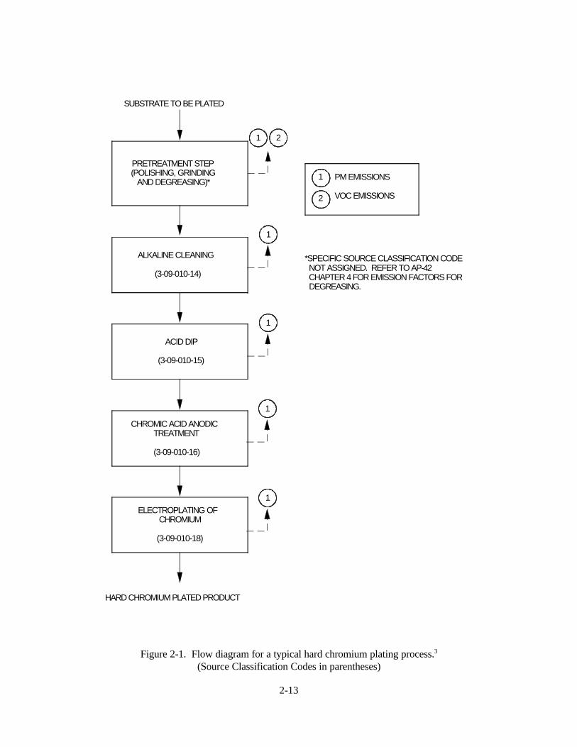
A flow diagram for a typical hard chromium plating process is presented in Figure 2-1. Theprocess consists of the following steps:
1. Pretreatment (polishing, grinding, degreasing);2. Alkaline cleaning and acid dipping (optional);3. Chromic acid anodic treatment (optional); and4. Chromium electroplating.
The part being plated is rinsed after each step in the process to prevent carry-over of solution that maycontaminate the baths used in successive process steps. Either hot or cold water may be used in rinsetanks, but hot water is more efficient than cold water for removing contaminants. Softened, distilled, ordeionized water may be required for final rinses.
Pretreatment steps include polishing, grinding, and/or degreasing the metal part to prepare thesurface for plating. Polishing and grinding are performed to smooth the surface of the part. Degreasing isperformed either by dipping the part in organic solvents or by vapor degreasing the part using organicsolvents. Vapor degreasing is typically used when the surface loading of oil or grease is excessive. Thetwo organic solvents most commonly used in dipping solutions or for vapor degreasing aretrichloroethylene and perchloroethylene. In vapor degreasing, the solvent is boiled in a tank and the vaporcondenses on the part and removes the oil and grease from its surface. Vapor degreasers must be fittedwith a local ventilation system designed to pick up solvent vapors escaping from the tanks without pullingvapor from the machine itself.

2-3
Alkaline cleaning is sometimes used to dislodge surface soil and prevent it from settling back ontothe metal. These cleaning solutions are typically made of compounds such as sodium carbonate, sodiumphosphate, and sodium hydroxide and usually contain a surfactant. Alkaline cleaning techniques includesoaking and cathodic and anodic cleaning. In soaking, the metal is placed in an alkaline bath that isagitated mildly. In cathodic cleaning, the metal is placed in an alkaline bath and direct current is applied. The part acts as the cathode; therefore, when current is applied, hydrogen gas evolves, enhancing thedetergent action of the solution. Two disadvantages of cathodic cleaning are that impurities in the cleaningsolution may be deposited on the metal and hydrogen may embrittle the metal. In anodic cleaning, the partis placed in an alkaline bath and reverse current is applied. The part then acts as the anode so that whenthe current is applied, oxygen gas is evolved. One disadvantage of anodic cleaning is that oxides may formon the surface of the metal. Also, anodic cleaning is less efficient than cathodic cleaning because oxygengas is liberated at one-half the rate that hydrogen gas is liberated during cathodic cleaning. During alkalinecleaning, an alkaline mist can be released at a fairly high rate because of the hydrogen and oxygen gasesentrapping the solution and releasing it as the bubbles burst at the surface; therefore, adequate ventilationshould be provided.
Acid dips may be used to remove any tarnish or oxide films formed in the alkaline cleaning stepand to neutralize the alkaline film. Acid dip solutions typically contain from 10 to 30 percent by volumehydrochloric or sulfuric acid in water. Because of the release of hydrogen and oxygen gases, an acid mistis generated from the dip tanks at varying rates and, as with alkaline cleaning, proper ventilation should beprovided.
A chromic acid anodic treatment step is sometimes included. This treatment cleans the metalsurface, with the evolution of oxygen gas scouring the metal. The chromic acid also activates the surface,which enhances the adhesion of chromium in the electroplating step. A typical bath contains chromic acidin a concentration that ranges from 120 to 240 grams per liter (g/L) (16 to 32 ounces per gallon [oz/gal]) attemperatures ranging from 49E to 66EC (120E to 150EF). Satisfactory cleaning and activation of thesurface are usually obtained at 6 volts (V) and a current density ranging from 1,550 to 4,650 amperes persquare meter (A/m2) (140 to 430 amperes per square foot [A/ft2]) for 1 to 3 minutes. Anodic treatment istypically accomplished by applying reverse current in the hard chromium plating tank. The anodictreatment also adds a protective oxide layer to the metal so that the chromium can be plated withoutapplying an undercoating of nickel.
The final step of the process is the chromium electroplating operation. Chromium electroplatingrequires constant control of the plating bath temperature, current density, plating time, and bathcomposition.
Tanks used for hard chromium electroplating usually are constructed of steel and lined with apolyvinyl chloride sheet or plastisol. The anodes, which are insoluble, are made of a lead alloy thatcontains either tin or antimony. The substrate is suspended from a plating rack that is connected to thecathode bar of the rectifier. The plating rack may be loaded in the tank manually, by a hoist, or by anautomatically controlled hoist system.
The plating tanks typically are equipped with some type of heat exchanger. Mechanical agitatorsor compressed air supplied through pipes on the tank bottom provide uniformity of bath temperature andcomposition. Hexavalent chromium plating baths are the most widely used baths to deposit chromium onmetal. Hexavalent chromium baths are composed of chromic acid, sulfuric acid, and water. The chromicacid is the source of the hexavalent chromium that reacts and deposits on the metal and is emitted to the

2-4
atmosphere. The sulfuric acid in the bath catalyzes the chromium deposition reactions. Typical operatingparameters are given in Table 2-2.
The evolution of hydrogen gas from chemical reactions at the cathode consumes 80 to 90 percentof the power supplied to the plating bath, leaving the remaining 10 to 20 percent for the deposition reaction. When the hydrogen gas evolves, it entrains chromic acid and causes misting at the surface of the platingbath.
2.2.1.2 Decorative Chromium Electroplating of Metals. In decorative plating, the base material(e.g., brass, steel, aluminum, or plastic) generally is plated with layers of copper and nickel followed by arelatively thin layer of chromium to provide a bright surface with wear and tarnish resistance. Decorativeplating is used for items such as automotive trim, metal furniture, bicycles, hand tools, and plumbingfixtures. The purpose of decorative chromium plating is to achieve a combination of the following surfaceproperties:
1. Blue-white color;2. High reflectivity;3. Tarnish resistance;4. Corrosion resistance;5. Wear resistance; and6. Scratch resistance.
The decorative chromium plating process consists of a series of plating operations. Figure 2-2presents a process flow diagram for the decorative chromium plating of metals (i.e., brass, steel, andaluminum). The process consists of the following steps:
1. Pretreatment (polishing, grinding, degreasing);2. Alkaline cleaning;3. Acid dipping;4. Strike plating of copper;5. Electroplating of copper;6. Electroplating of nickel; and7. Electroplating of chromium.
As with hard chromium plating, the part being plated is rinsed after each step in the process to preventcarry-over of solution that may contaminate the baths used in successive process steps. Either hot or coldwater may be used in the rinse tanks, but hot water is more efficient than cold water for removingcontaminants. Softened, distilled, or deionized water may be required for final rinses.
Decorative electroplating baths operate on the same principle as that described of the hardchromium plating process: the metal substrate is immersed in a plating solution, and direct current ispassed from the anode through the plating solution causing the desired metal (copper, nickel, chromium) todeposit out of the solution onto the metal substrate (cathode).
Pretreatment steps include polishing, grinding, and/or degreasing the part to prepare for plating. Polishing and grinding are performed to smooth the surface of the part. Alkaline cleaning may be used todislodge surface soil and prevent it from settling back onto the metal. Acid dipping is sometimes used toremove tarnish or oxide films formed in the alkaline cleaning step. Acid dips are also typically used
2-5
following strike plating of copper. These steps are described in more detail in Section 2.2.2.1 for hardchromium plating.
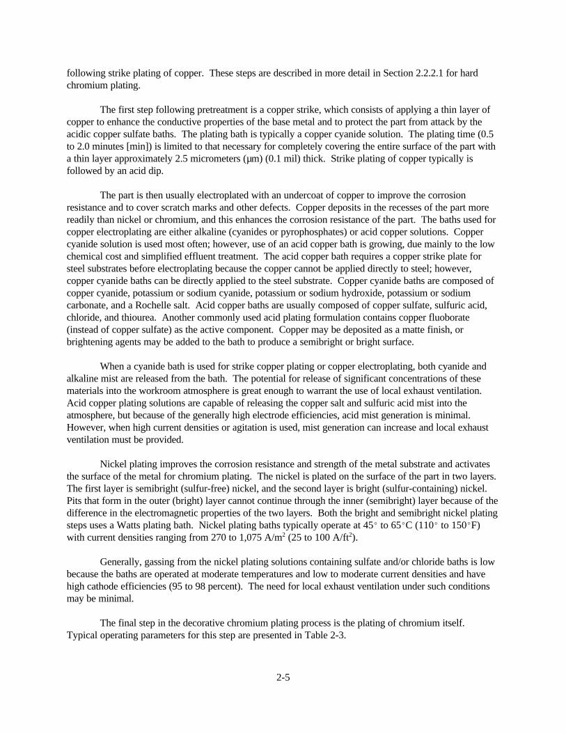
The first step following pretreatment is a copper strike, which consists of applying a thin layer ofcopper to enhance the conductive properties of the base metal and to protect the part from attack by theacidic copper sulfate baths. The plating bath is typically a copper cyanide solution. The plating time (0.5to 2.0 minutes [min]) is limited to that necessary for completely covering the entire surface of the part witha thin layer approximately 2.5 micrometers (µm) (0.1 mil) thick. Strike plating of copper typically isfollowed by an acid dip.
The part is then usually electroplated with an undercoat of copper to improve the corrosionresistance and to cover scratch marks and other defects. Copper deposits in the recesses of the part morereadily than nickel or chromium, and this enhances the corrosion resistance of the part. The baths used forcopper electroplating are either alkaline (cyanides or pyrophosphates) or acid copper solutions. Coppercyanide solution is used most often; however, use of an acid copper bath is growing, due mainly to the lowchemical cost and simplified effluent treatment. The acid copper bath requires a copper strike plate forsteel substrates before electroplating because the copper cannot be applied directly to steel; however,copper cyanide baths can be directly applied to the steel substrate. Copper cyanide baths are composed ofcopper cyanide, potassium or sodium cyanide, potassium or sodium hydroxide, potassium or sodiumcarbonate, and a Rochelle salt. Acid copper baths are usually composed of copper sulfate, sulfuric acid,chloride, and thiourea. Another commonly used acid plating formulation contains copper fluoborate(instead of copper sulfate) as the active component. Copper may be deposited as a matte finish, orbrightening agents may be added to the bath to produce a semibright or bright surface.
When a cyanide bath is used for strike copper plating or copper electroplating, both cyanide andalkaline mist are released from the bath. The potential for release of significant concentrations of thesematerials into the workroom atmosphere is great enough to warrant the use of local exhaust ventilation. Acid copper plating solutions are capable of releasing the copper salt and sulfuric acid mist into theatmosphere, but because of the generally high electrode efficiencies, acid mist generation is minimal. However, when high current densities or agitation is used, mist generation can increase and local exhaustventilation must be provided.
Nickel plating improves the corrosion resistance and strength of the metal substrate and activatesthe surface of the metal for chromium plating. The nickel is plated on the surface of the part in two layers. The first layer is semibright (sulfur-free) nickel, and the second layer is bright (sulfur-containing) nickel. Pits that form in the outer (bright) layer cannot continue through the inner (semibright) layer because of thedifference in the electromagnetic properties of the two layers. Both the bright and semibright nickel platingsteps uses a Watts plating bath. Nickel plating baths typically operate at 45E to 65EC (110E to 150EF)with current densities ranging from 270 to 1,075 A/m2 (25 to 100 A/ft2).
Generally, gassing from the nickel plating solutions containing sulfate and/or chloride baths is lowbecause the baths are operated at moderate temperatures and low to moderate current densities and havehigh cathode efficiencies (95 to 98 percent). The need for local exhaust ventilation under such conditionsmay be minimal.
The final step in the decorative chromium plating process is the plating of chromium itself. Typical operating parameters for this step are presented in Table 2-3.

2-6
Decorative chromium plating requires shorter plating times and operates at lower current densitiesthan does hard chromium plating to achieve the desired properties of the chromium plate. Some decorativechromium plating operations use fluoride catalysts instead of sulfuric acid because fluoride catalysts, suchas fluosilicate or fluoborate, have been found to produce higher bath efficiencies.
2.2.1.3 Decorative Chromium Electroplating of Plastics. Most plastics that are electroplated withchromium are formed from the polymer composed of acrylonitrile, butadiene, and styrene (ABS). Theprocess for chromium electroplating of ABS plastics consists of the following steps:
1. Chromic acid/sulfuric acid etch;2. Dilute hydrochloric acid dip;3. Colloidal palladium activation;4. Dilute hydrochloric acid dip;5. Electroless nickel plating or copper plating; and6. Chromium electroplating cycle.
After each process step, the plastic is rinsed with water to prevent carry-over of solution from onebath to another. The chromic acid/sulfuric acid etch solution (see Table 2-4) renders the ABS surfacehydrophilic and modifies the surface to provide adhesion for the metal coating. The dilute hydrochloricacid dips are used to clean the surface and remove palladium metal from the plating rack, which isinsulated with a coating of polyvinyl chloride. The colloidal palladium activation solution deposits a thinlayer of metallic palladium over the plastic surface. The metallic palladium induces the deposition ofcopper or nickel which will not deposit directly onto plastic. The electroless nickel and copper plate areapplied to impart electrical conductivity to the part; otherwise, the insulating surface of the plastic couldnot be electroplated with chromium. The electroless nickel plating or copper electroplating baths develop afilm on the plastic about 1.0 Fm (3.9 x 10⁻⁵ inch [in.]) thick. The plating time for electroless nickel platingand electroless copper plating ranges from 10 to 15 minutes and 15 to 30 minutes, respectively, attemperatures ranging from 25E to 35EC (77E to 95EF). The components of the plating baths include themetal salt (nickel or copper), a reducing agent, a complexing agent, a stabilizer, and a pH buffer system. The electroplating of plastics follows the same cycle as that described for decorative chromiumelectroplating.
2.2.1.4 Chromic Acid Anodizing. Chromic acid anodizing is used primarily on aircraft parts andarchitectural structures that are subject to high stress and corrosion. Chromic acid anodizing is used toprovide an oxide layer on aluminum that imparts the following properties:
1. Corrosion protection;2. Electrical insulation;3. Ease of coloring; and4. Improved dielectric strength.
Figure 2-3 presents a flow diagram for a typical chromic acid anodizing process.
There are four primary differences between the equipment used for chromium electroplating andthat used for chromic acid anodizing: (a) chromic acid anodizing requires the rectifier to be fitted with arheostat or other control mechanism to permit starting at about 5 V, (b) the tank is the cathode in theelectrical circuit, (c) the aluminum substrate acts as the anode, and (d) sidewall shields typically are used
2-7
instead of a liner in the tank to minimize short circuits and to decrease the effective cathode area. Types ofshield materials used are herculite glass, wire safety glass, neoprene, and vinyl chloride polymers.
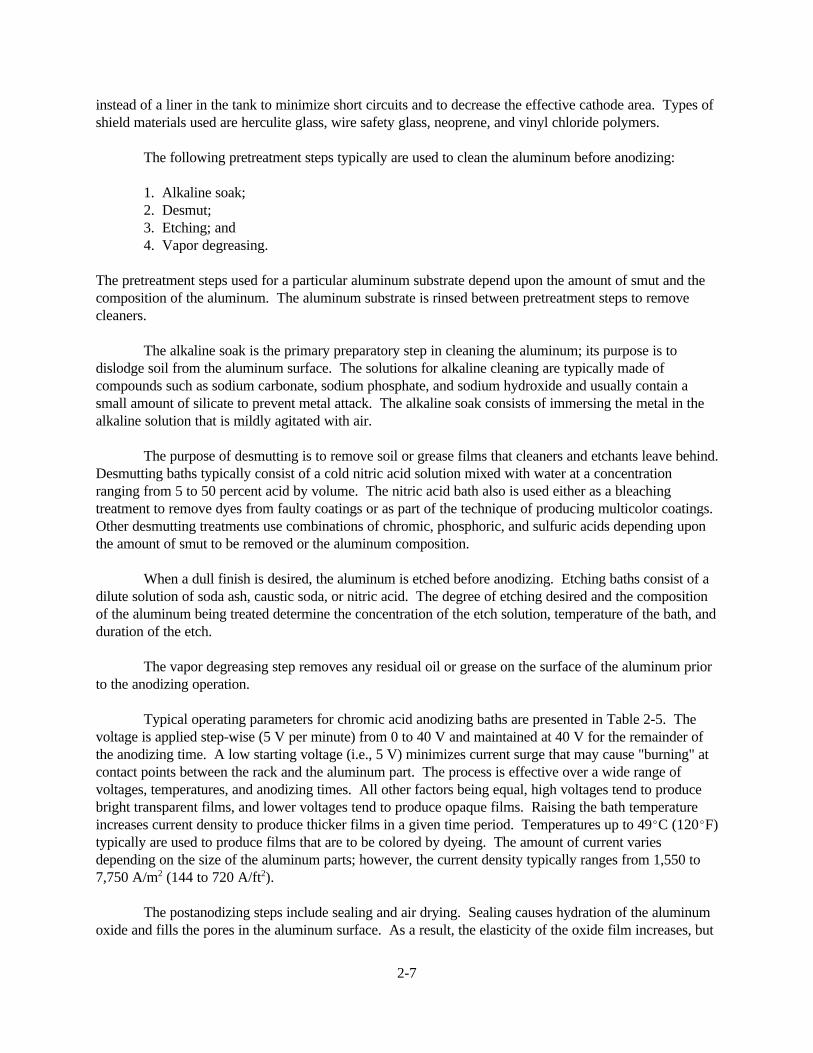
The following pretreatment steps typically are used to clean the aluminum before anodizing:
1. Alkaline soak;2. Desmut;3. Etching; and4. Vapor degreasing.
The pretreatment steps used for a particular aluminum substrate depend upon the amount of smut and thecomposition of the aluminum. The aluminum substrate is rinsed between pretreatment steps to removecleaners.
The alkaline soak is the primary preparatory step in cleaning the aluminum; its purpose is todislodge soil from the aluminum surface. The solutions for alkaline cleaning are typically made ofcompounds such as sodium carbonate, sodium phosphate, and sodium hydroxide and usually contain asmall amount of silicate to prevent metal attack. The alkaline soak consists of immersing the metal in thealkaline solution that is mildly agitated with air.
The purpose of desmutting is to remove soil or grease films that cleaners and etchants leave behind. Desmutting baths typically consist of a cold nitric acid solution mixed with water at a concentrationranging from 5 to 50 percent acid by volume. The nitric acid bath also is used either as a bleachingtreatment to remove dyes from faulty coatings or as part of the technique of producing multicolor coatings. Other desmutting treatments use combinations of chromic, phosphoric, and sulfuric acids depending uponthe amount of smut to be removed or the aluminum composition.
When a dull finish is desired, the aluminum is etched before anodizing. Etching baths consist of adilute solution of soda ash, caustic soda, or nitric acid. The degree of etching desired and the compositionof the aluminum being treated determine the concentration of the etch solution, temperature of the bath, andduration of the etch.
The vapor degreasing step removes any residual oil or grease on the surface of the aluminum priorto the anodizing operation.
Typical operating parameters for chromic acid anodizing baths are presented in Table 2-5. Thevoltage is applied step-wise (5 V per minute) from 0 to 40 V and maintained at 40 V for the remainder ofthe anodizing time. A low starting voltage (i.e., 5 V) minimizes current surge that may cause "burning" atcontact points between the rack and the aluminum part. The process is effective over a wide range ofvoltages, temperatures, and anodizing times. All other factors being equal, high voltages tend to producebright transparent films, and lower voltages tend to produce opaque films. Raising the bath temperatureincreases current density to produce thicker films in a given time period. Temperatures up to 49EC (120EF)typically are used to produce films that are to be colored by dyeing. The amount of current variesdepending on the size of the aluminum parts; however, the current density typically ranges from 1,550 to7,750 A/m2 (144 to 720 A/ft2).
The postanodizing steps include sealing and air drying. Sealing causes hydration of the aluminumoxide and fills the pores in the aluminum surface. As a result, the elasticity of the oxide film increases, but

2-8
the hardness and wear resistance decrease. Sealing is performed by immersing aluminum in a water bath at88E to 99EC (190E to 210EF) for a minimum of 15 minutes. Chromic acid or other chromates may beadded to the solution to help improve corrosion resistance. The aluminum is allowed to air dry after it issealed.
2.2.1.5 Trivalent Chromium Plating. Trivalent chromium electroplating baths have beendeveloped primarily to replace decorative hexavalent chromium plating baths. Development of a trivalentbath has proven to be difficult because trivalent chromium solvates in water to form complex stable ionsthat do not readily release chromium. The trivalent chromium baths that have been developed areproprietary baths.
There are two types of trivalent chromium processes on the market: single-cell and double-cell. The major differences in the two processes are that (1) the double-cell process solution containsminimal-to-no chlorides whereas the single-cell process solution contains a high concentration of chlorides;and (2) the double-cell process utilizes lead anodes that are placed in anode boxes that contain a dilutesulfuric acid solution and are lined with a permeable membrane whereas the single-cell process utilizescarbon or graphite anodes that are placed in direct contact with the plating solution.
The advantages of the trivalent chromium processes over the hexavalent chromium process are(1) fewer environmental concerns due to the lower toxicity of trivalent chromium, (2) higher productivity,and (3) lower operating costs. In the trivalent chromium process, hexavalent chromium is a plating bathcontaminant. Therefore, the bath does not contain any appreciable amount of hexavalent chromium. Thetotal chromium concentration of trivalent chromium solutions is approximately one-fifth that of hexavalentchromium solutions. As a result of the chemistry of the trivalent chromium electrolyte, misting does notoccur during plating as it does during hexavalent chromium plating. Use of trivalent chromium alsoreduces waste disposal problems and costs. Waste treatment of hexavalent chromium is a two-stageprocess. The hexavalent chromium is first reduced to the trivalent chromium ion; then it can beprecipitated as chromium hydroxide. Trivalent chromium plating solution wastewaters are already in thereduced trivalent state and require only the chromium hydroxide precipitation step.
Productivity is increased when trivalent chromium processes are used because less stripping andreplating of parts are required, more parts can be placed on a rack, and more racks can be placed on aworkbar.
The cost of operating a trivalent chromium process is less than that of a hexavalent chromiumprocess because of the lower wastewater treatment costs, a reduction in rejects, and high productivity.
The disadvantages of the trivalent chromium process are that the process is more sensitive tocontamination than the hexavalent chromium process, and the trivalent chromium process cannot plate thefull range of plate thicknesses that the hexavalent chromium process can. Because it is sensitive tocontamination, the trivalent chromium process requires more thorough rinsing and tighter laboratorycontrol than does the hexavalent chromium process. Trivalent chromium baths can plate thicknessesranging up to 0.13 to 25 Fm (0.005 to 1.0 mils) and, therefore, cannot be used for most hard chromiumplating applications. The hexavalent chromium process can plate thicknesses up to 762 Fm (30 mils).
The plating efficiency of a trivalent chromium bath, approximately 20 to 25 percent, is slightlyhigher than that of a hexavalent chromium plating bath. The color, hardness, and corrosion resistance oftrivalent chromium deposits are comparable to those of hexavalent chromium deposits. However, the

2-9
composition of a trivalent chromium deposit differs significantly from that of a hexavalent chromiumdeposit. Table 2-6 presents the composition of trivalent and hexavalent chromium deposits.
2.2.1.6 Emissions From Chromium Electroplating. Plating operations generate mists due to theevolution of hydrogen and oxygen gas. The gases are formed in the process tanks on the surface of thesubmerged part or on anodes or cathodes. As these gas bubbles rise to the surface, they escape into the airand may carry considerable liquid with them in the form of a fine mist. The rate of gassing is a function ofthe chemical or electrochemical activity in the tank and increases with the amount of work in the tank, thestrength and temperature of the solution, and the current densities in the plating tanks.
Emissions are also generated from surface preparation steps (alkaline cleaning, acid dipping, andvapor degreasing). These emissions are in the form of alkaline and acid mists and solvent vapors. Theextent of acid misting from the plating processes (copper, nickel, and chromium) depends mainly on theefficiency of the plating bath. Both copper and nickel plating baths have high cathode efficiencies so thatthe generation of mist is minimal. However, the cathode efficiency of chromium plating baths is very low(10 to 20 percent), and a substantial quantity of chromic acid mist is generated.
Emissions of chromic acid mist from the electrodeposition of chromium from chromic acid platingbaths occur because of the inefficiency of the hexavalent chromium plating process. Only about 10 to20 percent of the current applied actually is used to deposit chromium on the item plated; the remaining 80to 90 percent of the current applied is consumed by the evolution of hydrogen gas at the cathode with theresultant liberation of gas bubbles. Additional bubbles are formed at the anode due to the evolution ofoxygen. As the bubbles burst at the surface of the plating solution, a fine mist of chromic acid droplets isformed.
2.2.1.7 Emission Control Technology for Chromium Electroplating. The principal techniquesused to control emissions of chromic acid mist from decorative and hard chromium plating and chromicacid anodizing operations include add-on control devices and chemical fume suppressants. The controldevices most frequently used are mist eliminators and wet scrubbers that are operated at relatively lowpressure drops. Because of the corrosive properties of chromic acid, control devices typically are made ofpolyvinyl chloride (PVC) or fiberglass.
Chemical fume suppressants are added to decorative chromium plating and chromic acid anodizingbaths to reduce chromic acid mist. Although chemical agents alone are effective control techniques, manyplants use them in conjunction with an add-on control device.
Chevron-blade and mesh-pad mist eliminators are the types of mist eliminators most frequentlyused to control chromic acid mist. The most important mechanism by which mist eliminators removechromic acid droplets from gas streams is the inertial impaction of droplets onto a stationary set of bladesor a mesh pad. Mist eliminators typically are operated as dry units that are periodically washed down withwater to clean the impaction media.
The wet scrubbers typically used to control emissions of chromic acid mist from chromium platingand chromic acid anodizing operations are single and double packed-bed scrubbers. Other scrubber typesused less frequently include fan-separator packed-bed and centrifugal-flow scrubbers. Scrubbers removechromic acid droplets from the gas stream by humidifying the gas stream to increase the mass of the dropletparticles, which are then removed by impingement on a packed bed. Once-through water or recirculatedwater typically is used as the scrubbing liquid because chromic acid is highly soluble in water.

2-10
Chemical fume suppressants are surface-active compounds that are added directly to chromiumplating and chromic acid anodizing baths to reduce or control misting. Fume suppressants are classified astemporary or as permanent. Temporary fume suppressants are depleted mainly by the decomposition of thefume suppressant and dragout of the plating solution, and permanent fume suppressant are depleted mainlyby dragout of the plating solution. Fume suppressants, which are manufactured in liquid, powder, or tabletform, include wetting agents that reduce misting by lowering the surface tension of the plating or anodizingbath, foam blankets that entrap chromic acid mist at the surface of the plating solution, or combinations ofboth a wetting agent and foam blanket. Polypropylene balls, which float on the surface of the platingbaths, also are used as a fume suppressant in chromium plating tanks.
Table 2-7 presents control efficiency for general types of chromium electroplating emission controltechnologies based on data from EPA-sponsored emission tests.
For decorative chromium plating operations, the performance efficiency of both chemical fumesuppressants tested (a foam blanket and a combination of a foam blanket and wetting agent) is greater than99 percent. This performance efficiency is achievable as long as vendor recommendations on the makeupand use of the fume suppressants are followed rigorously.
2.2.2 Other Types of Electroplating4-18
The following paragraphs provide a brief overview of electroplating of metals other thanchromium. The metals addressed include brass, cadmium, copper, gold, indium, iron, nickel, palladium,platinum, rhodium, ruthenium, silver, tin, lead, and zinc.
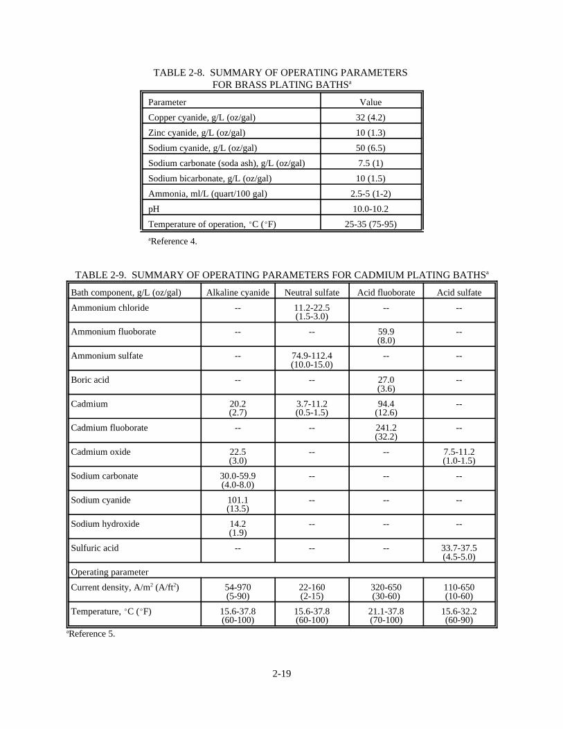
2.2.2.1 Brass. Brass, which is an alloy of copper and zinc, is the most widely used alloyelectroplate. Brass plating primarily is used for decorative applications, but it is also used for engineeringapplications such as for plating steel wire cord for steel-belted radial tires. Although all of the alloys ofcopper and zinc can be plated, the brass alloy most often used includes 70 to 80 percent copper, with thebalance zinc. Table 2-8 lists the important constituents of the solution and operating parameters for platingthis alloy.
2.2.2.2 Cadmium. Cadmium plating generally is performed in alkaline cyanide baths that areprepared by dissolving cadmium oxide in a sodium cyanide solution. However, because of the hazardsassociated with cyanide use, noncyanide cadmium plating solutions are being used more widely. Theprimary noncyanide plating solutions are neutral sulfate, acid fluoborate, and acid sulfate. Table 2-9 liststhe main constituents and operating parameters for both cyanide and noncyanide cadmium platingsolutions.
2.2.2.3 Copper. Copper cyanide plating is widely used in many plating operations as a strike. However, its use for thick deposits is decreasing. For copper cyanide plating, cuprous cyanide must becomplexed with either potassium or sodium to form soluble copper compounds in aqueous solutions. Table 2-10 summarizes the operating parameters for both potassium and sodium cyanide plating baths.
Other types of baths used in copper plating include copper pyrophosphate and copper sulfatebaths. Copper pyrophosphate plating, which is used for plating on plastics and printed circuits, requiresmore control and maintenance of the plating baths than copper cyanide plating does. However, copperpyrophosphate solutions are relatively nontoxic. Table 2-11 summarizes the operating parameters for atypical copper pyrophosphate plating operation.

2-11
Copper sulfate baths, which are more economical to prepare and operate than copperpyrophosphate baths, are used for plating printed circuits, electronics, rotogravure, and plastics, and forelectroforming and decorative uses. In this type of bath copper and sulfate and sulfuric acid form theionized species in solution. Table 2-12 summarizes the operating parameters for a typical copper sulfateplating operation.
2.2.2.4 Gold. Gold and gold alloy plating are used in a wide variety of applications. Gold platingsolutions can be classified in five general groups: alkaline gold cyanide, for gold and gold alloy plating;neutral cyanide gold, for high purity gold plating; acid gold cyanide, for bright hard gold and gold alloyplating; noncyanide (generally sulfite), for gold and gold plating; and miscellaneous. Tables 2-13 to 2-15summarize the operating parameters for alkaline gold cyanide, neutral gold cyanide, and acid gold cyanideplating operations, respectively.
2.2.2.5 Indium. In general, indium is electroplated using three types of plating baths: cyanide,sulfamate, and fluoborate. Tables 2-16 to 2-18 summarize the operating parameters for indium cyanide,indium sulfamate, and indium fluoborate plating operations, respectively. Indium is the only trivalent metalthat can be electrodeposited readily from a cyanide solution. Cyanide baths are used in applications thatrequire very high throwing power and adhesion. Indium sulfamate baths are very stable, relatively easy tocontrol, and are characterized by a high cathode efficiency that remains relatively high (90 percent).
2.2.2.6 Iron. Iron is electroplated using chloride, sulfate, sulfamate, or fluoborate plating baths. However, because of its poor metallurgical properties, iron plating is used rarely and is not discussedfurther in this report.
2.2.2.7 Nickel. Nickel plating is used for decorative, engineering, and electroforming purposes. Table 2-19 summarizes the operating parameters for several types of baths used in both engineering anddecorative nickel plating. Decorative nickel plating differs from other types of nickel plating in that thesolutions contains organic agents, such as benzene disulfonic acids, benzene trisulfonic acid, naphthalenetrisulfonic acid, benzene sulfonamide, formaldehyde, coumarin, ethylene cyanohydrin, and butynediol. Nickel plating for engineering applications uses solutions that deposit pure nickel. Table 2-20 summarizesthe operating parameters for nickel electroforming.
2.2.2.8 Palladium and Palladium-Nickel. Palladium plating solutions are categorized asammoniacal, chelated, or acid. Table 2-21 summarizes the operating parameters of two types ofammoniacal plating baths, and Table 2-22 summarizes the parameters for acid plating baths.
Palladium alloys readily with other metals, the most important of which is nickel. Table 2-23summarizes the operating parameters for a palladium-nickel plating.
2.2.2.9 Platinum. Solutions used for platinum plating are similar to those used for palladiumplating. Table 2-24 summarizes the operating parameters for three types of platinum plating baths.
2.2.2.10 Rhodium. Rhodium plating traditionally has been used as decorative plating in jewelryand silverware. However, the use of rhodium plating for electronics and other industrial applications hasbeen increasing in recent years. Table 2-25 summarizes the operating parameters for three types ofdecorative rhodium plating solutions and Table 2-26 summarizes the operating for electronic/industrialrhodium plating solutions.

2-12
2.2.2.11 Ruthenium. Electroplated ruthenium is a very good electrical conductor and produces avery hard deposit. Table 2-27 summarizes the operating parameters of a general purpose ruthenium platingbath.
2.2.2.12 Silver. Silver plating traditionally has been performed using a cyanide-based platingsolution. Although some noncyanide solutions have been developed, due to various shortcomings, cyanidesolutions still are commonly used. Table 2-28 summarizes the operating parameters of the traditionalcyanide-based silver plating bath.
2.2.2.13 Tin-Lead, Lead, and Tin. Fluoborate and fluoboric acid can be used to plate allpercentages of tin and lead. Alloys of tin and lead are most commonly used for plating in the proportionsof 60 percent tin and 40 percent lead. Table 2-29 summarizes the operating parameters for a typical 60/40tin lead plating bath. Table 2-30 summarizes the parameters for lead fluoborate, which is the acceptedelectrolyte for lead plating.
Tin plating generally is performed using one of three types of plating solutions (stannousfluoborate, stannous sulfate, or sodium or potassium stannate), or by the halogen tin process. Theoperating parameters for the stannous fluoborate, stannous sulfate, and sodium/potassium stannate bathsare summarized in Tables 2-31 to 2-33.
2.2.2.14 Tin-Nickel. Tin-nickel alloy plating is used in light engineering and electronicapplications and is used as an alternative to decorative chromium plating. The operating parameters fortin-nickel plating solutions, which generally are fluoride- or pyrophosphate-base, are summarized inTables 2-34 and 2-35.
2.2.2.15 Zinc. The most widely used zinc plating solutions are categorized as acid chloride,alkaline noncyanide, and cyanide. Table 2-36 summarizes the operating parameters for these three types ofplating baths. The most widely used zinc alloys for electroplating are zinc-nickel, zinc-cobalt, and zinc-iron. The operating parameters for the baths used in these operations are summarized in Tables 2-37 to2-39.
2-13
1
2
PM EMISSIONS
VOC EMISSIONS
PRETREATMENT STEP(POLISHING, GRINDING
AND DEGREASING)*
ALKALINE CLEANING
(3-09-010-14)
ACID DIP
(3-09-010-15)
CHROMIC ACID ANODICTREATMENT
(3-09-010-16)
ELECTROPLATING OFCHROMIUM
(3-09-010-18)
SUBSTRATE TO BE PLATED
HARD CHROMIUM PLATED PRODUCT
1 2
1
1
1
1
*SPECIFIC SOURCE CLASSIFICATION CODE NOT ASSIGNED. REFER TO AP-42 CHAPTER 4 FOR EMISSION FACTORS FOR DEGREASING.
Figure 2-1. Flow diagram for a typical hard chromium plating process.3
(Source Classification Codes in parentheses)

2-14
PRETREATMENT STEP(POLISHING, GRINDING, AND
DEGREASING)*
ALKALINE CLEANING
(3-09-010-14)
ACID DIP
(3-09-010-15)
STRIKE PLATING OF COPPER
(3-09-010-42)
ACID DIP
(3-09-010-15)
ELECTROPLATING OF COPPER
(3-09-010-42, -45, -48)
ELECTROPLATING OF CHROMIUM
(3-09-010-28)
METAL SUBSTRATE TO BE PLATED
DECORATIVE CHROMIUM PLATED PRODUCT
1 2
1
1
1
1
1
ELECTROPLATING OF SEMIBRIGHT(WATTS) NICKEL
(3-09-010-65)
1
ELECTROPLATING OF BRIGHT (WATTS) NICKEL
(3-09-010-65)
1
1
1
2
PM EMISSIONS
VOC EMISSIONS
*SPECIFIC SOURCE CLASSIFICATION CODE NOT ASSIGNED. REFER TO AP-42 CHAPTER 4 FOR EMISSION FACTORS FOR DEGREASING.
Figure 2-2. Flow diagram for decorative chromium plating on a metal substrate.3
(Source Classification Codes in parentheses).

2-15
1
2
PM EMISSIONS
VOC EMISSIONS(FROM DEGREASING)
*SPECIFIC SOURCE CLASSIFICATION CODE NOT ASSIGNED. REFER TO AP-42 CHAPTER 4 FOR EMISSION FACTORS FOR DEGREASING.
RINSE
RINSE
SUBSTRATE TO BE PLATED
PRETREATMENT STEPS
DESMUTTINGETCHINGVAPOR DEGREASING*
CHROMIC ACID ANODIZING
(3--09-010-38)
SEALING
FINAL PRODUCT
1
1 2
ALKALINE CLEANING
(3--09-010-14)
Figure 2-3. Flow diagram for a typical chromic acid anodizing process.3
(Source Classification Codes in parentheses).

2-16
TABLE 2-1. ELECTROPLATING APPLICATIONS AND PRINCIPAL METALS USEDa
Property/function Principal plating metals
Decorative Chromium, copper, nickel, brass, bronze, gold,silver, platinum-group, zinc
Corrosion resistance Nickel, chromium, electroless nickel, zinc, cadmium,copper and copper alloys
Wear, lubricity, hardness Chromium, electroless nickel, bronze, nickel,cadmium, metal composites
Bearings Copper and bronze, silver and silver alloys, lead-tin
Joining, soldering, brazing, electrical contactresistance, conductivity
Nickel, electroless nickel, electroless copper, copper,cadmium, gold, silver, lead-tin, tin, cobalt
Barrier coatings, antidiffusion, heat-treat, stop-off Nickel, cobalt, iron, copper, bronze, tin-nickel
Electromagnetic shielding Copper, electroless copper, nickel, or electrolessnickel, zinc
Paint/lacquer base, rubber bonding Zinc, tin, chromium, brass
Manufacturing: electroforming Copper, nickel
Manufacturing: electronic circuitry Electroless copper, copper, electroless nickel, nickel
Dimensional buildup, salvage of worn parts Chromium nickel, electroless nickel, iron
aReference 1.
TABLE 2-2. TYPICAL OPERATING PARAMETERS FOR HARD CHROMIUMELECTROPLATINGa
Parameter Range of values
Plating thickness, Fm (mil) 1.3-762 (0.05-30)
Plating time, minb 20-2,160
Chromic acid concentration, g/L (oz/gal)c 225-375 (30-50)
Sulfuric acid concentration, g/L (oz/gal) 2.25-3.75 (0.3-0.5)
Temperature of solution, EC (EF) 49-66 (120-150)
Voltage, volts d
Current, A e
Current density, A/m2 (A/ft2)f 1,600-6,500 (150-600)
Cathode efficiency, % 10-20
aReference 2.bmin = minutes.cg/L = grams per liter, oz/gal = ounces per gallon.dDepends on the distance between the anodes and the items being plated.eDepends on the amount of surface area plated.fA/m2 = amperes per square meter (square foot) of surface area plated.

2-17
TABLE 2-3. TYPICAL OPERATING PARAMETERS FOR DECORATIVE CHROMIUMPLATING
Parameter Range of values
Plating thickness, Fm (mil) 0.003-2.5 (0.001-0.1)
Plating time, min 0.5-5
Chromic acid concentration, g/L (oz/gal) 225-375 (30-50)
Sulfuric acid concentration, g/L (oz/gal) 2.25-3.75 (0.3-0.5)
Temperature of solution, EC (EF) 38-46 (100-115)
Voltage, volts b
Current, A c
Current density, A/m2 (A/ft2)d 540-2,400 (50-220)
Cathode efficiency, % 10-20
aReference 2.bDepends on the distance between the anodes and the items being plated.cDepends on the amount of surface area being plated.dAmperes per square meter (square foot) of surface area plated.
TABLE 2-4. TYPICAL OPERATING PARAMETERS FOR CHROMIC ACID/SULFURIC ACID ETCH SOLUTIONa
Parameter Values
Concentrated sulfuric acid, g/L (oz/gal) 172 (23)
Chromic acid, g/L (oz/gal) 430 (57)
Temperature, EC (EF) 60-65 (140-149)
Immersion time, min 3-10
aReference 2.
TABLE 2-5. TYPICAL OPERATING PARAMETERS FOR CHROMICACID ANODIZING
Parameter Range of values
Chromic acid concentration, g/L (oz/gal) 50-100 (6.67-13.3)
Temperature, EC (EF) 32-35 (90-95)
Plating time, min 30-60
pH 0.5-0.85
Current density, A/m2 (A/ft2)b 1,550-7,750 (144-720)
Voltage (step-wise), volts 30-40
Film thickness, Fm (mil) 0.5-1.27 (0.02-0.05)
aReference 2.bAmperes per square meter (square foot) of surface area plated.

2-18
TABLE 2-6. HEXAVALENT AND TRIVALENT CHROMIUM DEPOSIT COMPOSITIONSa
Type of chromiumdeposit Carbon, weight percent Oxygen, weight percent
Chromium, weightpercent
Hexavalent 0.0 0.4 99+
Trivalent 2.9 1.6 95+
aReference 2.
TABLE 2-7. PERFORMANCE LEVELS OF CHROMIUM ELECTROPLATING EMISSIONCONTROL TECHNOLOGIESa
Control device
Hexavalent chromiummass emission,
kg/hr x 10-3 Range of controldevice efficiencies,
percent
Hexavalent chromiumemission concentration,
mg/dscm x 10-3
Inlet Outlet Inlet Outlet
Chevron-blade mist eliminatorsbcd 26
1576
3.31.31.2
83.1-91.086.9-95.198.0-98.7
2,0301,7607,960
310150120
Mesh-pad mist eliminatorseff 31
8324
0.40.230.27
98.4-99.099.2-99.998.7-99.0
3,07011,4004,410
403343
Packed-bed scrubbersghjkm
9046232224
0.521.51.20.710.65
99.1-99.694.9-98.194.3-95.196.3-97.297.2-97.3
5,5101,670
715668723
3052392321
Polypropylene ballsn
22 5.4 68.0-81.9 3,980 960
Fume suppressantpq 3.6
3.60.020.01
99.3-99.699.7-99.9
921921
4.72.2
aReference 3.bChevron-blade mist eliminator with a single set of sinusoidal wave-type blades.cChevron-blade mist eliminator with a single set of overlapping-type blades.dChevron-blade mist eliminator with a double set of overlapping-type blades.eMist eliminator containing a double set of overlapping-type chevron blades followed by two mesh pads in series. Moistureextractor preceded mist eliminator. Tests were conducted at the inlet to the moisture extractor and at the outlet of the misteliminator.
fDouble mesh-pad mist eliminator.gSingle packed-bed, horizontal-flow wet scrubber.hDouble packed-bed, horizontal-flow wet scrubber.jSingle packed-bed, horizontal flow wet scrubber. No overhead washdown of the scrubber packing.kSingle packed-bed, horizontal flow wet scrubber. Periodic overhead washdown of the scrubber packing.mSingle packed-bed, horizontal flow wet scrubber. Continuous overhead washdown of the scrubber packing.nTests were conducted at the mist eliminator inlet with and without polypropylene balls. Polypropylene balls 3.8 cm in diameter with two to three layers of coverage.pFoam blanket.qWetting agent in combination with a foam blanket.
2-19
TABLE 2-8. SUMMARY OF OPERATING PARAMETERS FOR BRASS PLATING BATHSa
Parameter Value
Copper cyanide, g/L (oz/gal) 32 (4.2)
Zinc cyanide, g/L (oz/gal) 10 (1.3)
Sodium cyanide, g/L (oz/gal) 50 (6.5)
Sodium carbonate (soda ash), g/L (oz/gal) 7.5 (1)
Sodium bicarbonate, g/L (oz/gal) 10 (1.5)
Ammonia, ml/L (quart/100 gal) 2.5-5 (1-2)
pH 10.0-10.2
Temperature of operation, EC (EF) 25-35 (75-95)
aReference 4.
TABLE 2-9. SUMMARY OF OPERATING PARAMETERS FOR CADMIUM PLATING BATHSa
Bath component, g/L (oz/gal) Alkaline cyanide Neutral sulfate Acid fluoborate Acid sulfate
Ammonium chloride -- 11.2-22.5(1.5-3.0)
-- --
Ammonium fluoborate -- -- 59.9(8.0)
--
Ammonium sulfate -- 74.9-112.4(10.0-15.0)
-- --
Boric acid -- -- 27.0(3.6)
--
Cadmium 20.2(2.7)
3.7-11.2(0.5-1.5)
94.4(12.6)
--
Cadmium fluoborate -- -- 241.2(32.2)
--
Cadmium oxide 22.5(3.0)
-- -- 7.5-11.2(1.0-1.5)
Sodium carbonate 30.0-59.9(4.0-8.0)
-- -- --
Sodium cyanide 101.1(13.5)
-- -- --
Sodium hydroxide 14.2(1.9)
-- -- --
Sulfuric acid -- -- -- 33.7-37.5(4.5-5.0)
Operating parameter
Current density, A/m2 (A/ft2) 54-970(5-90)
22-160(2-15)
320-650(30-60)
110-650(10-60)
Temperature, EC (EF) 15.6-37.8(60-100)
15.6-37.8(60-100)
21.1-37.8(70-100)
15.6-32.2(60-90)
aReference 5.

2-20
TABLE 2-10. SUMMARY OF OPERATING PARAMETERS FOR COPPER POTASSIUMAND SODIUM CYANIDE PLATING BATHSa
Parameter
Value
Potassium Sodium
Copper cyanide, g/L (oz/gal) 30 (4.0) 30.0 (4.0)
Total potassium cyanide, g/L (oz/gal) 58.5 (7.8) --
Total sodium cyanide, g/L (oz/gal) -- 48.0 (6.4)
Potassium hydroxide, g/L (oz/gal) 3.75-7.5 (0.5-1.0) --
Sodium hydroxide, g/L (oz/gal) --
Potassium carbonate, g/L (oz/gal) 15.0 (2.0 )
Sodium carbonate, g/L (oz/gal) 15.0 (2.0)
Rochelle salt, g/L (oz/gal) 30.0 (4.0) 30.0 (4.0)
Free potassium cyanide by analysis, g/L (oz/gal) 11.25-15.0 (1.5-2.0)
Free sodium cyanide by analysis, g/L (oz/gal) -- 11.25-15.0 (1.5-2.0)
Temperature, EC (EF) 24-66 (75-140)
Current density, A/m2 (A/ft2) 54-430 (5-40)
Time, min 0.5-2 or until fully covered
Cathode efficiency, % 30-60
Recommended agitation None or mechanicalaReference 6.
TABLE 2-11. SUMMARY OF OPERATING PARAMETERS FOR COPPERPYROPHOSPHATE PLATING BATHSa
Parameter Value
Copper pyrophosphate (Cu2P2O7•3H2O), g/L (oz/gal) 52.5-84.0 (7.0-11.2)
Potassium pyrophosphate (K4P2O7), g/L (oz/gal) 201.1-349.1 (26.8-46.5)
Potassium nitrate, g/L (oz/gal) 3.0-6.0 (0.4-0.8)
Concentrated ammonium hydroxide, ml/L (oz/gal) 3.75-11.0 (0.5-1.5)
pH 8.0-8.7
Temperature, EC (EF) 43-60 (110-140)
Current density, A/m2 (A/ft2) 110-860 (10.0-80.0)
Agitation Mechanical and air
Filtration ContinuousaReference 6.

2-21
TABLE 2-12. SUMMARY OF OPERATING PARAMETERS FOR COPPER SULFATE PLATING BATHSa
Parameter Value
General formation:
Copper sulfate, g/L (oz/gal) 195-248 (26-33)
Sulfuric acid, g/L (oz/gal) 30-75 (4-10)
Chloride, ppm 50-120
Current density, A/m2 (A/ft2) 215-1,080 (20-100)
Semibright plating (Clifton-Phillips):
Copper sulfate, g/L (oz/gal) 248 (33)
Sulfuric acid, g/L (oz/gal) 11 (1.5)
Chloride, ppm 50-120
Thiourea, g/L (oz/gal) 0.00075 (0.0001)
Wetting agent, g/L (oz/gal) 0.2 (0.027)
Bright plating (Beaver):
Copper sulfate, g/L (oz/gal) 210 (28)
Sulfuric acid, g/L (oz/gal) 60 (8)
Chloride, ppm 50-120
Thiourea, g/L (oz/gal) 0.1 (0.0013)
Dextrin, g/L (oz/gal) 0.01 (0.0013)
Bright plating (Clifton-Phillips):
Copper sulfate, g/L (oz/gal) 199 (26.5)
Sulfuric acid, g/L (oz/gal) 30 (4)
Chloride, ppm 50-120
Thiourea, g/L (oz/gal) 0.0375 (0.005)
Molasses, g/L (oz/gal) 0.75 (0.1)
aReference 6.
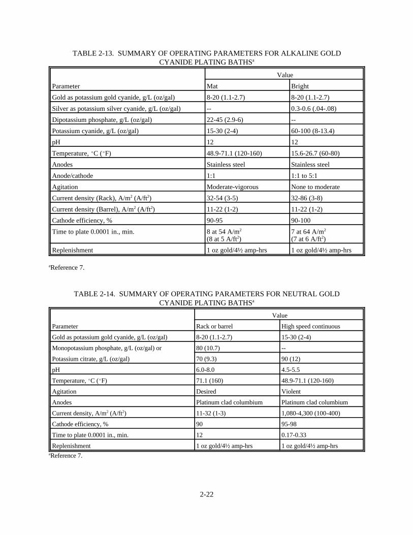
2-22
TABLE 2-13. SUMMARY OF OPERATING PARAMETERS FOR ALKALINE GOLDCYANIDE PLATING BATHSa
Parameter
Value
Mat Bright
Gold as potassium gold cyanide, g/L (oz/gal) 8-20 (1.1-2.7) 8-20 (1.1-2.7)
Silver as potassium silver cyanide, g/L (oz/gal) -- 0.3-0.6 (.04-.08)
Dipotassium phosphate, g/L (oz/gal) 22-45 (2.9-6) --
Potassium cyanide, g/L (oz/gal) 15-30 (2-4) 60-100 (8-13.4)
pH 12 12
Temperature, EC (EF) 48.9-71.1 (120-160) 15.6-26.7 (60-80)
Anodes Stainless steel Stainless steel
Anode/cathode 1:1 1:1 to 5:1
Agitation Moderate-vigorous None to moderate
Current density (Rack), A/m2 (A/ft2) 32-54 (3-5) 32-86 (3-8)
Current density (Barrel), A/m2 (A/ft2) 11-22 (1-2) 11-22 (1-2)
Cathode efficiency, % 90-95 90-100
Time to plate 0.0001 in., min. 8 at 54 A/m2 (8 at 5 A/ft2)
7 at 64 A/m2
(7 at 6 A/ft2)
Replenishment 1 oz gold/4½ amp-hrs 1 oz gold/4½ amp-hrs
aReference 7.
TABLE 2-14. SUMMARY OF OPERATING PARAMETERS FOR NEUTRAL GOLDCYANIDE PLATING BATHSa
Parameter
Value
Rack or barrel High speed continuous
Gold as potassium gold cyanide, g/L (oz/gal) 8-20 (1.1-2.7) 15-30 (2-4)
Monopotassium phosphate, g/L (oz/gal) or 80 (10.7) --
Potassium citrate, g/L (oz/gal) 70 (9.3) 90 (12)
pH 6.0-8.0 4.5-5.5
Temperature, EC (EF) 71.1 (160) 48.9-71.1 (120-160)
Agitation Desired Violent
Anodes Platinum clad columbium Platinum clad columbium
Current density, A/m2 (A/ft2) 11-32 (1-3) 1,080-4,300 (100-400)
Cathode efficiency, % 90 95-98
Time to plate 0.0001 in., min. 12 0.17-0.33
Replenishment 1 oz gold/4½ amp-hrs 1 oz gold/4½ amp-hrsaReference 7.

2-23
TABLE 2-15. SUMMARY OF OPERATING PARAMETERS FOR ACID GOLD CYANIDEPLATING BATHSa
Parameter
Value
Barrel Rack or barrel High speed/continuous
Mat Bath No. 1 Bright Bath No. 2
Gold as potassium gold cyanide,g/L (oz/gal)
8 (1.1) 8 (1.1) 8-16 (1.1-2.1)
Citric acid, g/L (oz/gal) 60 (8) 60 (8) 90 (12)
Cobalt as cobalt metal, g/L(oz/gal) or
-- 0.2-0.5 (.03-.07) 0.75 (0.1)
Nickel as nickel metal, g/L(oz/gal)
pH 3.8-5.0 3.8-4.5 3.8-4.3
Temperature, EC (EF) 49-60 (120-140) 21-32 (70-90) 21-49 (70-120)
Anodes Platinum clad Platinum clad or stainlesssteel
Platinum clad
Agitation Desirable Desirable Violent
Current density, A/m2 (A/ft2) 11-54 (1-5) 54-220 (5-20) 1,080-4,300 (100-400)
Cathode efficiency, % 30-40 30-40
Time to plate 0.0001 in., min. 10 at 108 A/m2
(10 at 10 A/ft2)0.25 at 4,300 A/m2
(0.25 at 400 A/ft2)
Replenishment 1 oz/gold/12 amp-hrs 1 oz gold/12 amp-hrsaReference 7.
TABLE 2-16. SUMMARY OF OPERATING PARAMETERS FOR INDIUM CYANIDEPLATING BATHSa
Parameter Value
Indium as metal, g/L (oz/gal) 33 (4)
Dextrose, g/L (oz/gal) 33 (4)
Total cyanide (KCN), g/L (oz/gal) 96 (12.8)
Potassium hydroxide (KOH), g/L (oz/gal) 64 (8.5)
Temperature (static) Room temperature
Cathode efficiency, % 50-75
Anodes Plain steel
Throwing power Excellent
Quality of plate Excellent
Ease of solution analysis Difficult
Critical temperature (working) None, with or without agitation
Wettability Easy
Tendency to pit None
Control of solution Cyanide and metal by additions
Use General
Current density, A/m2 (A/ft2) 162-216 (15-20)
pH High pHaReference 8.
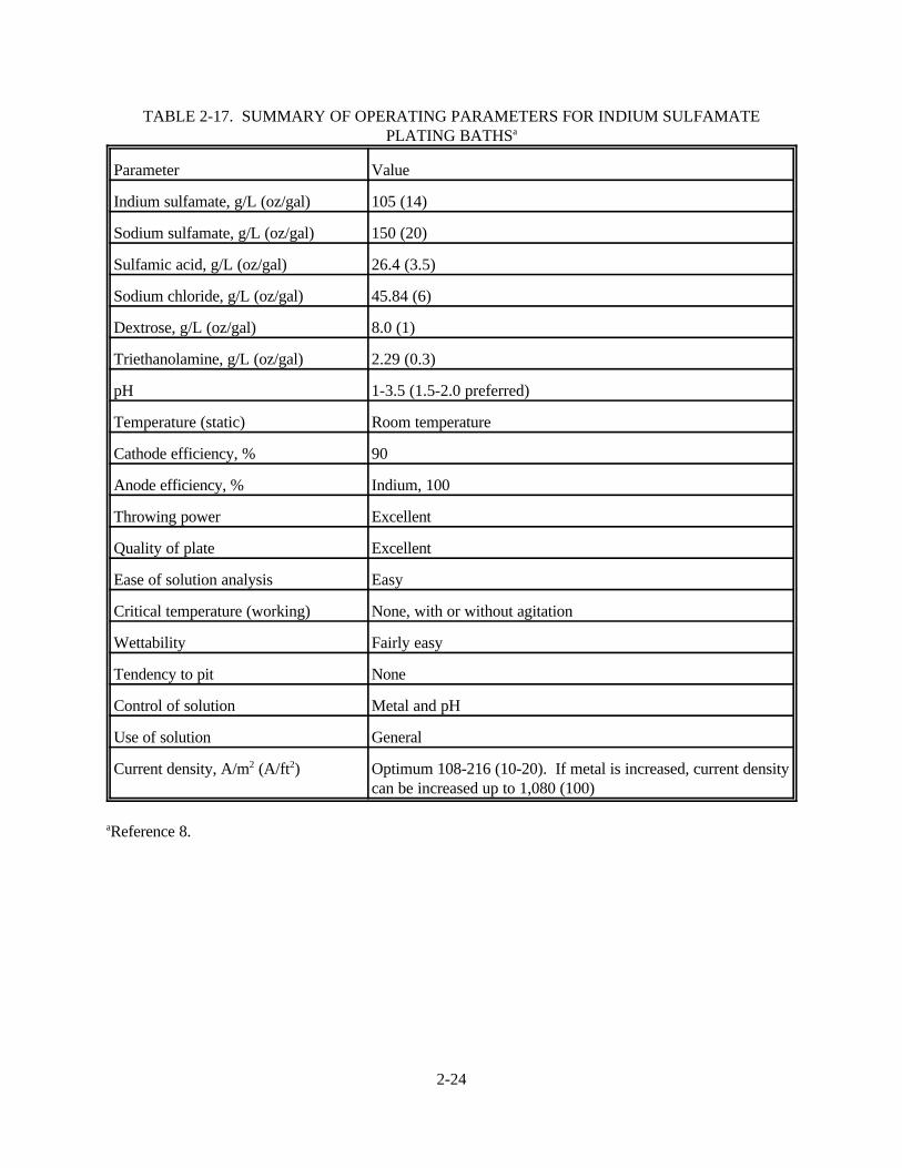
2-24
TABLE 2-17. SUMMARY OF OPERATING PARAMETERS FOR INDIUM SULFAMATEPLATING BATHSa
Parameter Value
Indium sulfamate, g/L (oz/gal) 105 (14)
Sodium sulfamate, g/L (oz/gal) 150 (20)
Sulfamic acid, g/L (oz/gal) 26.4 (3.5)
Sodium chloride, g/L (oz/gal) 45.84 (6)
Dextrose, g/L (oz/gal) 8.0 (1)
Triethanolamine, g/L (oz/gal) 2.29 (0.3)
pH 1-3.5 (1.5-2.0 preferred)
Temperature (static) Room temperature
Cathode efficiency, % 90
Anode efficiency, % Indium, 100
Throwing power Excellent
Quality of plate Excellent
Ease of solution analysis Easy
Critical temperature (working) None, with or without agitation
Wettability Fairly easy
Tendency to pit None
Control of solution Metal and pH
Use of solution General
Current density, A/m2 (A/ft2) Optimum 108-216 (10-20). If metal is increased, current densitycan be increased up to 1,080 (100)
aReference 8.

2-25
TABLE 2-18. SUMMARY OF OPERATING PARAMETERS FOR INDIUM FLUOBORATEPLATING BATHSa
Parameter Value
Indium fluoborate, g/L (oz/gal) 236 (31.5)
Boric acid, g/L (oz/gal) 22-30 (2.9-4.0)
Ammonium fluoroborate, g/L (oz/gal) 40-50 (5.3-6.7)
pH (colorimetric) 1.0
Temperature (static) EC (EF) 21-32 (70-90)
Cathode efficiency, % 40-75
Anode efficiency, % Indium, 100
Throwing power Good
Quality of plate Good
Ease of solution analysis Easy
Critical temperature (working), EC(EF)
21-32 (70-90) with or without agitation
Wettability Difficult
Tendency to pit None
Control of solution Metal and pH
Use General
Current density, A/m2 (A/ft2) 540-1,080 (50-100)
aReference 8.
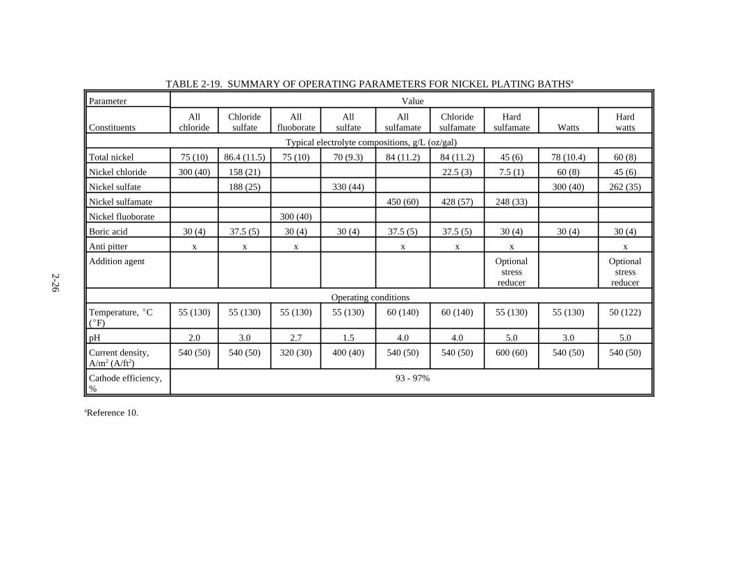
2-26
TABLE 2-19. SUMMARY OF OPERATING PARAMETERS FOR NICKEL PLATING BATHSa
Parameter Value
ConstituentsAll
chlorideChloridesulfate
Allfluoborate
Allsulfate
Allsulfamate
Chloridesulfamate
Hardsulfamate Watts
Hardwatts
Typical electrolyte compositions, g/L (oz/gal)
Total nickel 75 (10) 86.4 (11.5) 75 (10) 70 (9.3) 84 (11.2) 84 (11.2) 45 (6) 78 (10.4) 60 (8)
Nickel chloride 300 (40) 158 (21) 22.5 (3) 7.5 (1) 60 (8) 45 (6)
Nickel sulfate 188 (25) 330 (44) 300 (40) 262 (35)
Nickel sulfamate 450 (60) 428 (57) 248 (33)
Nickel fluoborate 300 (40)
Boric acid 30 (4) 37.5 (5) 30 (4) 30 (4) 37.5 (5) 37.5 (5) 30 (4) 30 (4) 30 (4)
Anti pitter x x x x x x x
Addition agent Optionalstress
reducer
Optionalstress
reducer
Operating conditions
Temperature, EC(EF)
55 (130) 55 (130) 55 (130) 55 (130) 60 (140) 60 (140) 55 (130) 55 (130) 50 (122)
pH 2.0 3.0 2.7 1.5 4.0 4.0 5.0 3.0 5.0
Current density,A/m2 (A/ft2)
540 (50) 540 (50) 320 (30) 400 (40) 540 (50) 540 (50) 600 (60) 540 (50) 540 (50)
Cathode efficiency,%
93 - 97%
aReference 10.

2-27
TABLE 2-20. SUMMARY OF OPERATING PARAMETERS FOR NICKELELECTROFORMING BATHSa
Parameter
Value
Watts nickel Nickel sulfamate
Electrolyte composition, g/L (oz/gal) NiSO4•6H2O — 225-300 (30-40)NiCl2•6H2O — 37.5-52.5 (5-7)H3BO3 — 30-45 (4-6)
Ni(SO3,NH2) — 315-450 (42-60)H2BO2 — 30-45 (4-6)NiCl2•6H2O — 0-22.5 (0-3)
Operating conditions
Temperature, EC (EF) 44-66 (115-150) 32-60 (90-140)
Agitation Air or mechanical Air or mechanical
Cathode current density, A/m2 (A/ft2) 270-1,075 (25-100) 50-3,225 (5-300)
Anodes Soluble nickel Soluble nickel
pH 3.0-4.2 3.5-4.5
aReference 10.
TABLE 2-21. SUMMARY OF OPERATING PARAMETERS FOR PALLADIUMAMMONIACAL PLATING BATHSa
Parameter Value
P-salt/sulfamate:
Palladium as Pd (NH3)2(NO2)2, g/L (oz/gal)Ammonium sulfamate, g/L (oz/gal)Ammonium hydroxide to pHTemperature, EC (EF)Current density, A/m2 (A/ft2)Anodes
10-15 (1.3-2)100 (13.4)7.5-8.525-33 (77-91)1-20 (0.093-1.86)Platinized
Palladosamine chloride:
Palladium as Pd(NH3)4Cl2, g/L (oz/gal)Ammonium chloride, g/L (oz/gal)Ammonium hydroxide to pHTemperature, EC (EF)Current density, A/m2 (A/ft2)Anodes
10-15 (1.3-2)60-90 (8-12)8.0-9.525-50 (77-122)1-25 (0.093-2.32)Platinized
aReference 11.

2-28
TABLE 2-22. SUMMARY OF OPERATING PARAMETERS FOR PALLADIUM ACIDPLATING BATHSa
Parameter Value
P-salt/sulfamate:
Palladium as PdCl2, g/L (oz/gal)Ammonium chloride, g/L (oz/gal)Hydrochloric acidTemperature, EC (EF)Current density, A/m2 (A/ft2)AnodesCathode efficiency, %
50 (6.7)30 (4)to pH 0.1-0.540-50 (104-122)1-10 (0.093-0.93)Pure palladium97-100
aReference 11.
TABLE 2-23. SUMMARY OF OPERATING PARAMETERS FOR PALLADIUM-NICKELPLATING BATHSa
Parameter Value
Palladium as Pd (NH3)2(NO2)2 (palladium metal 3g/L), g/L (oz/gal)
6 (0.8)
Nickel sulfamate concentrate (nickel metal 3 g/L),g/L (oz/gal)
20 (2.7)
Ammonium sulfamate, g/L (oz/gal) 90 (12)
Ammonium hydroxide to pH 8-9
Temperature, EC (EF) 20-40 (68-104)
Anodes Platinized
aReference 11.
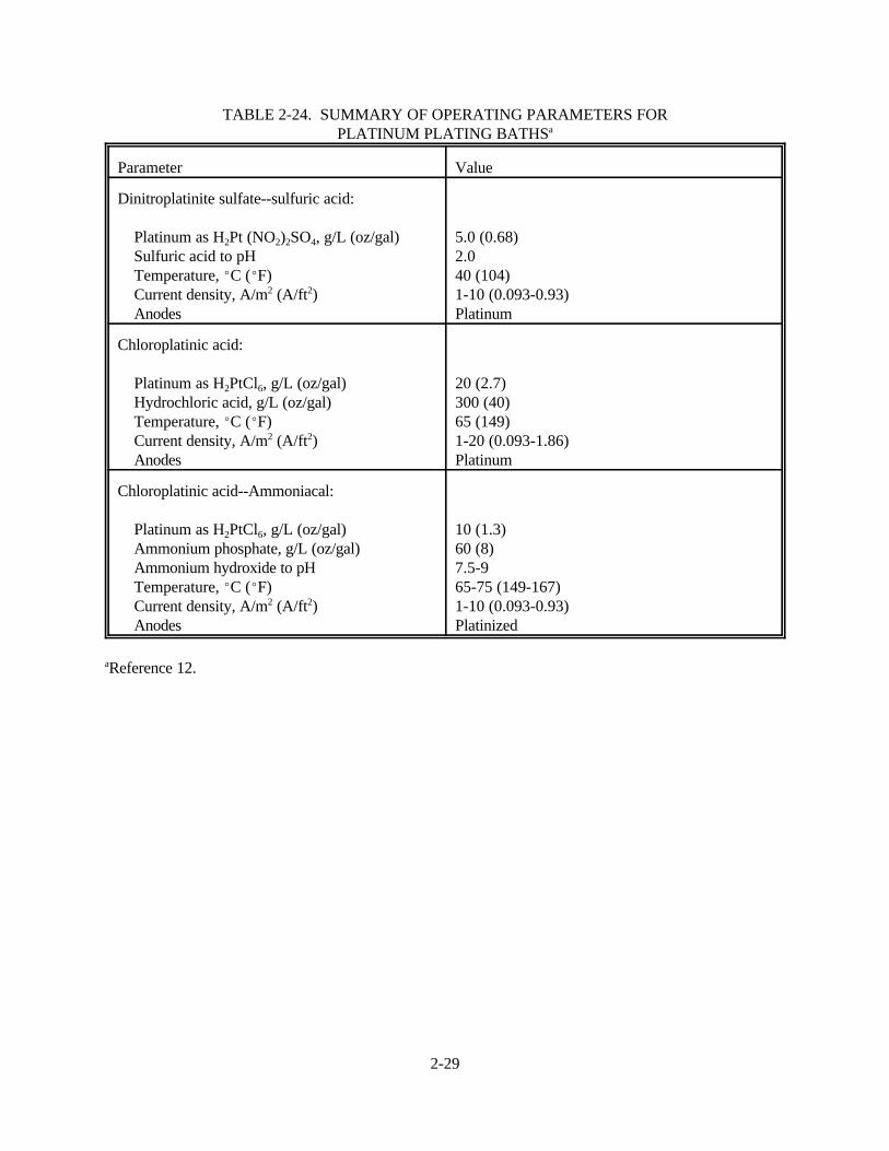
2-29
TABLE 2-24. SUMMARY OF OPERATING PARAMETERS FORPLATINUM PLATING BATHSa
Parameter Value
Dinitroplatinite sulfate--sulfuric acid:
Platinum as H2Pt (NO2)2SO4, g/L (oz/gal)Sulfuric acid to pHTemperature, EC (EF)Current density, A/m2 (A/ft2)Anodes
5.0 (0.68)2.040 (104)1-10 (0.093-0.93)Platinum
Chloroplatinic acid:
Platinum as H2PtCl6, g/L (oz/gal)Hydrochloric acid, g/L (oz/gal)Temperature, EC (EF)Current density, A/m2 (A/ft2)Anodes
20 (2.7)300 (40)65 (149)1-20 (0.093-1.86)Platinum
Chloroplatinic acid--Ammoniacal:
Platinum as H2PtCl6, g/L (oz/gal)Ammonium phosphate, g/L (oz/gal)Ammonium hydroxide to pHTemperature, EC (EF)Current density, A/m2 (A/ft2)Anodes
10 (1.3)60 (8)7.5-965-75 (149-167)1-10 (0.093-0.93)Platinized
aReference 12.

2-30
TABLE 2-25. SUMMARY OF OPERATING PARAMETERS FOR DECORATIVERHODIUM PLATING BATHSa
Parameter Value
Phosphate rhodium bath:
Rhodium as phosphate concentrate, g/L (oz/gal)Phosphoric acid (85% CP grade), ml/L (oz/gal)AnodesTemperature, EC (EF)AgitationCurrent density, A/m2 (A/ft2)
2.0 (0.27)40-80 (5.3-11)Platinum/platinum clad40-50 (104-122)None-moderate20-100 (1.86-9.3)
Sulfate rhodium bath:
Rhodium as sulfate concentrate, g/L (oz/gal)Sulfuric acid (95% CP grade), ml/L (oz/gal)AnodesTemperature, EC (EF)AgitationCurrent density, A/m2 (A/ft2)
1.3-2.0 (0.17-0.27)25-80 (3-11)Platinum/platinum clad40-50 (104-122)None-moderate20-100 (1.86-9.3)
Phosphate-sulfate rhodium bath:
Rhodium as phosphate concentrate, g/L (oz/gal)Sulfuric acid (95% CP grade), ml/L (oz/gal)AnodesTemperature, EC (EF)AgitationCurrent density, A/m2 (A/ft2)
2 (0.3)25-80 (3-11)Platinum/platinum clad40-50 (104-122)None-moderate20-100 (1.86-9.3)
aReference 13.
TABLE 2-26. SUMMARY OF OPERATING PARAMETERS FOR ELECTRONIC/INDUSTRIAL RHODIUM PLATING BATHSa
Parameter Value
Rhodium metal as sulfate concentrate, g/L (oz/gal) 5.0 (0.67)
Sulfuric acid (95% CP grade), ml/L (oz/gal) 25-50 (3-7)
Anodes Platinum/platinum clad
Temperature, EC (EF) 45-50 (113-122)
Current density, A/m2 (A/ft2) 10-30 (0.93-2.79)
Cathode efficiency, % 70-90 with agitation50-60 without agitation
aReference 13.

2-31
TABLE 2-27. SUMMARY OF OPERATING PARAMETERS FORRUTHENIUM PLATING BATHSa
Parameter Value
Ruthenium (as sulfamate or nitrosyl sulfamate),g/L (oz/gal)
5.3 (0.71)
Sulfamic acid, g/L (oz/gal) 8.0 (1.1)
Anodes Platinum
pH 1-2
Temperature, EC (EF) 27-60 (80-140) sulfamate21-88 (70-190) nitrosyl sulfamate
Current density, A/m2 (A/ft2) 108-320 (10-30)
Cathode efficiency, % 20
Time to plate 0.0001 in., min 30-40 at 215 A/m2
(30-40 at 20 A/ft2)
aReference 14.
TABLE 2-28. SUMMARY OF OPERATING PARAMETERS FOR SILVER CYANIDE PLATINGBATHSa
Parameter Value
Silver, as KAg (CN)2, g/L (oz/gal) 5-40 (0.67-5.3)
Potassium cyanide (free), g/L (oz/gal) 12-120 (1.6-16)
Potassium carbonate (min.), g/L (oz/gal) 15 (2)
Temperature, EC (EF) 20-30 (70-85)
Current density, A/m2 (A/ft2) 11-430 (1-40)
aReference 15.

2-32
TABLE 2-29. SUMMARY OF OPERATING PARAMETERS FOR60/40 TIN-LEAD PLATING BATHSa
Parameter
Value
Optimum Range
oz/gal g/L oz/gal g/L
Stannous tin 7.5 56.3 7-8 52.5-60
Lead 3.5 26.3 3-4 22.5-30
Fluoboric acid 13.3 99.8 13-20 98-150
Boric acid 3.5 26.3 3-5 22.5-37.5
Liquid peptone or 2.6 19.5 2-3 15-22.5
Peptone 0.7 5.3 0.6-0.9 4.5-7
Current density, A/m2 (A/ft2) 320 (30) 270-380 (25-35)
Anode to cathode ratio 2:1
Anodes 60/40 tin lead bagged with Dynel or polypropylene
Temperature, EC (EF) 20 (70) 15.5-27 (60-80)
Agitation Mild cathode rod
Filtration Continuous is recommended to maintain a clear solution.
aReference 16.
TABLE 2-30. SUMMARY OF OPERATING PARAMETERS FOR LEAD FLUOBORATEPLATING BATHSa
Parameter
Value
Optimum Range
oz/gal g/L oz/gal g/L
Lead fluoborate 50 375 45-55 337-412
Lead 29 218 26-32 195-239
Fluoboric acid 3 22.5 2-4 15-30
Boric acid 4 30 3-5 22.5-37.5
Liquid peptone or 2.6 19.5 2-3 15-22.5
Peptone 0.7 5.3 0.6-0.9 4.5-7
pH Less than 1
Current density, A/m2 (A/ft2) 215-750 (20-70)
Anode to cathode ratio 1:1
Anodes Pure lead
Temperature, EC (EF) 20-38 (70-100)
Agitation Mechanical
Filtration Will ensure smooth deposits. If solution is maintained under a constantlyoperated filter pump, it will assure the best agitation and filtration.
aReference 16.
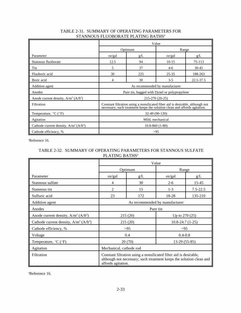
2-33
TABLE 2-31. SUMMARY OF OPERATING PARAMETERS FORSTANNOUS FLUOBORATE PLATING BATHSa
Parameter
Value
Optimum Range
oz/gal g/L oz/gal g/L
Stannous fluoborate 12.5 94 10-15 75-113
Tin 5 37 4-6 30-45
Fluoboric acid 30 225 25-35 188-263
Boric acid 4 30 3-5 22.5-37.5
Addition agent As recommended by manufacturer
Anodes Pure tin, bagged with Dynel or polypropylene
Anode current density, A/m2 (A/ft2) 215-270 (20-25)
Filtration Constant filtration using a nonsilicated fiber aid is desirable, although notnecessary; such treatment keeps the solution clean and affords agitation.
Temperature, EC (EF) 32-49 (90-120)
Agitation Mild, mechanical
Cathode current density, A/m2 (A/ft2) 10.8-860 (1-80)
Cathode efficiency, % >95
aReference 16.
TABLE 2-32. SUMMARY OF OPERATING PARAMETERS FOR STANNOUS SULFATEPLATING BATHSa
Parameter
Value
Optimum Range
oz/gal g/L oz/gal g/L
Stannous sulfate 4 30 2-6 15-45
Stannous tin 2 15 1-3 7.5-22.5
Sulfuric acid 23 172 18-28 135-210
Addition agent As recommended by manufacturer
Anodes Pure tin
Anode current density, A/m2 (A/ft2) 215 (20) Up to 270 (25)
Cathode current density, A/m2 (A/ft2) 215 (20) 10.8-24.7 (1-25)
Cathode efficiency, % >95 >95
Voltage 0.4 0.4-0.8
Temperature, EC (EF) 20 (70) 13-29 (55-85)
Agitation Mechanical, cathode rod
Filtration Constant filtration using a nonsilicated filter aid is desirable,although not necessary; such treatment keeps the solution clean andaffords agitation.
aReference 16.

2-34
TABLE 2-33. SUMMARY OF OPERATING PARAMETERS FOR SODIUM/POTASSIUM STANNATE PLATING BATHSa
Parameter
Value
Rack Barrel
oz/gal g/L oz/gal g/L
Sodium stannate bath
Sodium stannate 12 90 24 180
Tin metal 5.3 40 10.6 80
Free sodium hydroxide 1.6 12 3 22.5
Cathode current density, A/m2 (A/ft2) 162-216 (15-20) 54-162 (5-15)
Anode current density, A/m2 (A/ft2) 270 (25) 162-270 (15-25)
Voltage 3-4 3-4
Temperature, EC (EF) 77-82 (170-180) 74-79 (165-175)
Potassium stannate bath
Potassium stannate 13.3 100 26.6 200
Tin metal 5.3 40 10.6 80
Free potassium hydroxide 2 15 3 22.5
Cathode current density, A/m2 (A/ft2) 320-1,080 (30-100) 10.7-1,080 (1-100)
Anode current density, A/m2 (A/ft2) 320-430 (30-40) 108-320 (10-30)
Voltage 4-8 4-14
Temperature, EC (EF) 66-82 (150-180) 66-82 (150-180)
aReference 16.
TABLE 2-34. SUMMARY OF OPERATING PARAMETERS FOR TIN-NICKEL FLUORIDEPLATING BATHSa
Parameter Value
Solution composition:
Stannous chloride anhydrous (SnCl2), g/L (oz/gal)Nickel chloride (NiCl26H2O), g/L (oz/gal)Ammonium bifluoride (NH4HF2), g/L (oz/gal)
49 (6.5)300 (40)56 (7.5)
Control limits:
Stannous tin, g/L (oz/gal)Nickel, g/L (oz/gal)Total fluoride, g/L (oz/gal)pH
26-38 (3.5-5.0)60-83 (8.0-11.0)34-45 (4.5-6.0)2-2.5
Operating conditions:
Temperature, EC (EF)Voltage, VCathode current density, A/m2 (A/ft2)
65 (150)2-4 270 (25)
aReference 16.

2-35
TABLE 2-35. SUMMARY OF OPERATING PARAMETERS FOR TIN-NICKELPYROPHOSPHATE PLATING BATHSa
Parameter Value
Stannous chloride (SnCl22H2O), g/L (oz/gal) 28.2 (3.8)
Nickel chloride (NiCl26H2O), g/L (oz/gal) 31.3 (4.2)
Potassium pyrophosphate (K4P2O73H2O), g/L (oz/gal) 192.2 (25.8)
Glycine, g/L (oz/gal) 20.0 (2.7)
Temperature, EC (EF) 50 (122)
pH 7.5-8.5
Current density, A/m2 (A/ft2) 52-150 (4.8-14)
aReference 16.
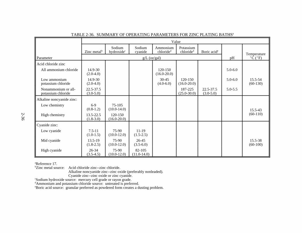
2-36
TABLE 2-36. SUMMARY OF OPERATING PARAMETERS FOR ZINC PLATING BATHSa
Parameter
Value
Zinc metalbSodium
hydroxidecSodiumcyanide
Ammoniumchlorided
Potassiumchlorided Boric acide
pHTemperatureEC (EF)g/L (oz/gal)
Acid chloride zinc
All ammonium chloride 14.9-30(2.0-4.0)
120-150(16.0-20.0)
5.0-6.0
Low ammoniumpotassium chloride
14.9-30(2.0-4.0)
30-45(4.0-6.0)
120-150(16.0-20.0)
5.0-6.0 15.5-54(60-130)
Nonammonium or all-potassium chloride
22.5-37.5(3.0-5.0)
187-225(25.0-30.0)
22.5-37.5(3.0-5.0)
5.0-5.5
Alkaline noncyanide zinc:
Low chemistry 6-9(0.8-1.2)
75-105(10.0-14.0) 15.5-43
(60-110)High chemistry 13.5-22.5(1.8-3.0)
120-150(16.0-20.0)
Cyanide zinc:
Low cyanide 7.5-11(1.0-1.5)
75-90(10.0-12.0)
11-19(1.5-2.5)
15.5-38(60-100)
Mid cyanide 13.5-19(1.8-2.5)
75-90(10.0-12.0)
26-45(3.5-6.0)
High cyanide 26-34(3.5-4.5)
75-90(10.0-12.0)
82-105(11.0-14.0)
aReference 17. bZinc metal source: Acid chloride zinc--zinc chloride.
Alkaline noncyanide zinc--zinc oxide (preferably nonleaded).Cyanide zinc--zinc oxide or zinc cyanide.
cSodium hydroxide source: mercury cell grade or rayon grade.dAmmonium and potassium chloride source: untreated is preferred.eBoric acid source: granular preferred as powdered form creates a dusting problem.

2-37
TABLE 2-37. SUMMARY OF OPERATING PARAMETERS FORZINC-NICKEL PLATING BATHSa
Parameter
Value
Rack Barrel
Acid zinc-nickel bath:
Zinc chloride, g/L (oz/gal) 130 (17) 120 (16)
Nickel chloride, g/L (oz/gal) 130 (17) 110 (15)
Potassium chloride, g/L (oz/gal) 230 (31) --
pH 5.0-6.0 5.0-6.0
Temperature, EC (EF) 24-30 (75-86) 35-40 (95-104)
Cathode current density, A/m2 (A/ft2) 10-40 (0.9-3.7) 5-30 (0.46-2.8)
Anodes Zinc and nickel separately. In some cases, separate rectifiers andbussing are required.
Alkaline zinc-nickel bath
Zinc metal, g/L (oz/gal) 8.0 (1.1)
Nickel metal, g/L (oz/gal) 1.6 (0.21)
Sodium hydroxide, g/L (oz/gal) 130 (17)
Ratio zinc/nickel, g/L (oz/gal) 5.0
Temperature, EC (EF) 23-26 (73-79)
Cathode current density, A/m2 (A/ft2) 20-100 (1.85-9.3)
Anode current density, A/m2 (A/ft2) 50-70 (4.6-6.5)
Anodes Pure zinc
aReference 18.

2-38
TABLE 2-38. SUMMARY OF OPERATING PARAMETERS FORZINC-COBALT PLATING BATHSa
Parameter
Value
Rack Barrel
Acid zinc-cobalt bath:
Zinc metal, g/L (oz/gal) 30 (4) 30 (4)
Potassium chloride, g/L (oz/gal) 180 (24) 225 (30)
Ammonium chloride, g/L (oz/gal) 45 (6) --
Cobalt (as metal), g/L (oz/gal) 1.9-3.8 (0.25-0.5) 1.9-3.8 (0.25-0.51)
Boric acid, g/L (oz/gal) 15-25 (2-3.3) 15-25 (2-3.3)
pH 5.0-6.0 5.0-6.0
Temperature, EC (EF) 21-38 (70-100) 21-38 (70-100)
Cathode current density, A/m2 (A/ft2) 1-50 (0.09-4.6) 10-500 (0.93-46)
Anodes Pure zinc Pure zinc
Alkaline zinc-cobalt bath:
Zinc metal, g/L (oz/gal) 6-9 (0.80-1.2)
Caustic soda, g/L (oz/gal) 75-105 (10-14)
Cobalt metal, g/L (oz/gal) 30-50 (0.004-0.007)
Temperature, EC (EF) 21-32 (70-90)
Cathode current density, A/m2 (A/ft2) 20-40 (1.9-3.7)
Anodes Steel
aReference 18.

2-39
TABLE 2-39. SUMMARY OF OPERATING PARAMETERS FOR ZINC-IRON PLATING BATHSa
Parameter Value
Acid zinc-iron bath:
Ferric sulfate, g/L (oz/gal) 200-300 (27-40)
Zinc sulfate, g/L (oz/gal) 200-300 (27-40)
Sodium sulfate, g/L (oz/gal) 30 (4)
Sodium acetate, g/L (oz/gal) 20 (2.7)
Alkaline zinc-iron bath:
Zinc metal, g/L (oz/gal) 20-25 (2.7-3.3)
Iron metal, g/L (oz/gal) 0.25-0.50 (0.033-0.067)
Caustic soda, g/L (oz/gal) 120-140 (16-19)
Temperature, EC (EF) 18-23 (64-73)
Cathode current density, A/m2 (A/ft2) 15-30 (1.4-2.8)
Anodes Steel
aReference 18.
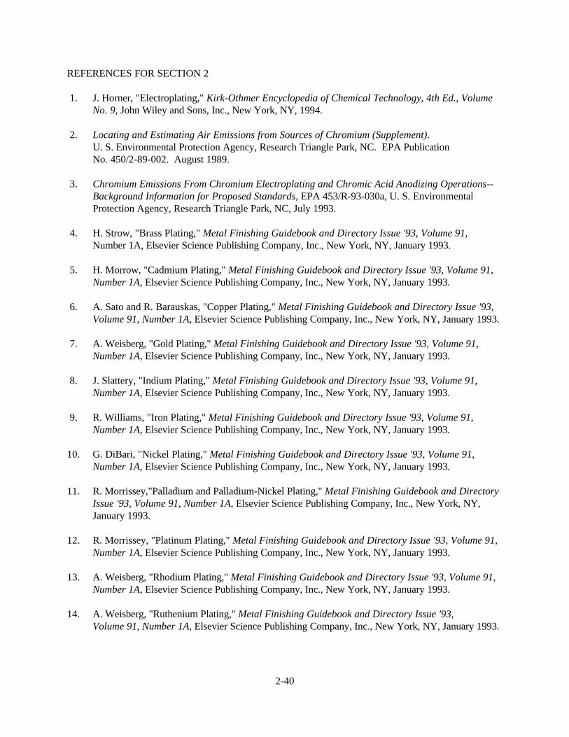
2-40
REFERENCES FOR SECTION 2
1. J. Horner, "Electroplating," Kirk-Othmer Encyclopedia of Chemical Technology, 4th Ed., VolumeNo. 9, John Wiley and Sons, Inc., New York, NY, 1994.
2. Locating and Estimating Air Emissions from Sources of Chromium (Supplement). U. S. Environmental Protection Agency, Research Triangle Park, NC. EPA PublicationNo. 450/2-89-002. August 1989.
3. Chromium Emissions From Chromium Electroplating and Chromic Acid Anodizing Operations--Background Information for Proposed Standards, EPA 453/R-93-030a, U. S. EnvironmentalProtection Agency, Research Triangle Park, NC, July 1993.
4. H. Strow, "Brass Plating," Metal Finishing Guidebook and Directory Issue '93, Volume 91,Number 1A, Elsevier Science Publishing Company, Inc., New York, NY, January 1993.
5. H. Morrow, "Cadmium Plating," Metal Finishing Guidebook and Directory Issue '93, Volume 91,Number 1A, Elsevier Science Publishing Company, Inc., New York, NY, January 1993.
6. A. Sato and R. Barauskas, "Copper Plating," Metal Finishing Guidebook and Directory Issue '93,Volume 91, Number 1A, Elsevier Science Publishing Company, Inc., New York, NY, January 1993.
7. A. Weisberg, "Gold Plating," Metal Finishing Guidebook and Directory Issue '93, Volume 91,Number 1A, Elsevier Science Publishing Company, Inc., New York, NY, January 1993.
8. J. Slattery, "Indium Plating," Metal Finishing Guidebook and Directory Issue '93, Volume 91,Number 1A, Elsevier Science Publishing Company, Inc., New York, NY, January 1993.
9. R. Williams, "Iron Plating," Metal Finishing Guidebook and Directory Issue '93, Volume 91,Number 1A, Elsevier Science Publishing Company, Inc., New York, NY, January 1993.
10. G. DiBari, "Nickel Plating," Metal Finishing Guidebook and Directory Issue '93, Volume 91,Number 1A, Elsevier Science Publishing Company, Inc., New York, NY, January 1993.
11. R. Morrissey,"Palladium and Palladium-Nickel Plating," Metal Finishing Guidebook and DirectoryIssue '93, Volume 91, Number 1A, Elsevier Science Publishing Company, Inc., New York, NY,January 1993.
12. R. Morrissey, "Platinum Plating," Metal Finishing Guidebook and Directory Issue '93, Volume 91,Number 1A, Elsevier Science Publishing Company, Inc., New York, NY, January 1993.
13. A. Weisberg, "Rhodium Plating," Metal Finishing Guidebook and Directory Issue '93, Volume 91,Number 1A, Elsevier Science Publishing Company, Inc., New York, NY, January 1993.
14. A. Weisberg, "Ruthenium Plating," Metal Finishing Guidebook and Directory Issue '93,Volume 91, Number 1A, Elsevier Science Publishing Company, Inc., New York, NY, January 1993.

2-41
15. A. Blair, "Silver Plating," Metal Finishing Guidebook and Directory Issue '93, Volume 91, Number1A, Elsevier Science Publishing Company, Inc., New York, NY, January 1993.
16. S. Hirsch, "Tin-Lead, Lead and Tin Plating," Metal Finishing Guidebook and Directory Issue '93,Volume 91, Number 1A, Elsevier Science Publishing Company, Inc., New York, NY, January 1993.
17. V. Kansupada, C. Biddulph, and M. Marzano, "Zinc Plating," Metal Finishing Guidebook andDirectory Issue '93, Volume 91, Number 1A, Elsevier Science Publishing Company, Inc., NewYork, NY, January 1993.
18. E. Budman, "Zinc Alloy Plating," Metal Finishing Guidebook and Directory Issue '93, Volume 91,Number 1A, Elsevier Science Publishing Company, Inc., New York, NY, January 1993.
3-1
3. GENERAL DATA REVIEW AND ANALYSIS PROCEDURES
3.1 LITERATURE SEARCH AND SCREENING
Data for this investigation were obtained from a number of sources within the Office of Air QualityPlanning and Standards (OAQPS) and from outside organizations. The AP-42 Background Files located inthe Emission Factors and Inventory Group (EFIG) were reviewed for information on the industry,processes, and emissions. The majority of information was obtained from the Emission Standards Division(ESD) project files on electroplating, the Locating and Estimating Air Emissions from Sources ofChromium document, and the national emission standards for hazardous air pollutants (NESHAP) forchromium electroplating. Additional emission test reports were obtained from the Source Test InformationRetrieval System (STIRS) data base. The American Electroplaters and Surface Finishers Society and theNational Association of Metal Finishers also were contacted for information on the industry.
To screen out unusable test reports, documents, and information from which emission factors couldnot be developed, the following general criteria were used:
1. Emission data must be from a primary reference:
a. Source testing must be from a referenced study that does not reiterate information fromprevious studies.
b. The document must constitute the original source of test data. For example, a technical paperwas not included if the original study was contained in the previous document. If the exact source of thedata could not be determined, the document was eliminated.
2. The referenced study should contain test results based on more than one test run. If resultsfrom only one run are presented, the emission factors must be down rated.
3. The report must contain sufficient data to evaluate the testing procedures and source operatingconditions (e.g., one-page reports were generally rejected).
A final set of reference materials was compiled after a thorough review of the pertinent reports,documents, and information according to these criteria.
3.2 DATA QUALITY RATING SYSTEM
As part of the analysis of the emission data, the quantity and quality of the information containedin the final set of reference documents were evaluated. The following data were excluded fromconsideration:
1. Test series averages reported in units that cannot be converted to the selected reporting units;
2. Test series representing incompatible test methods (i.e., comparison of EPA Method 5 front halfwith EPA Method 5 front and back half);
3. Test series of controlled emissions for which the control device is not specified;

3-2
4. Test series in which the source process is not clearly identified and described; and
5. Test series in which it is not clear whether the emissions were measured before or after thecontrol device.
Test data sets that were not excluded were assigned a quality rating. The rating system used wasthat specified by EFIG for preparing AP-42 sections. The data were rated as follows:
A--Multiple tests that were performed on the same source using sound methodology and reported inenough detail for adequate validation. These tests do not necessarily conform to the methodology specifiedin EPA reference test methods, although these methods were used as a guide for the methodology actuallyused.
B--Tests that were performed by a generally sound methodology but lack enough detail foradequate validation.
C--Tests that were based on an untested or new methodology or that lacked a significant amount ofbackground data.
D--Tests that were based on a generally unacceptable method but may provide an order-of-magnitude value for the source.
The following criteria were used to evaluate source test reports for sound methodology andadequate detail:
1. Source operation. The manner in which the source was operated is well documented in thereport. The source was operating within typical parameters during the test.
2. Sampling procedures. The sampling procedures conformed to a generally acceptablemethodology. If actual procedures deviated from accepted methods, the deviations are well documented. When this occurred, an evaluation was made of the extent to which such alternative procedures couldinfluence the test results.
3. Sampling and process data. Adequate sampling and process data are documented in the report,and any variations in the sampling and process operation are noted. If a large spread between test resultscannot be explained by information contained in the test report, the data are suspect and are given a lowerrating.
4. Analysis and calculations. The test reports contain original raw data sheets. The nomenclatureand equations used were compared to those (if any) specified by EPA to establish equivalency. The depthof review of the calculations was dictated by the reviewer's confidence in the ability and conscientiousnessof the tester, which in turn was based on factors such as consistency of results and completeness of otherareas of the test report.

3-3
3.3 EMISSION FACTOR QUALITY RATING SYSTEM1
The quality of the emission factors developed from analysis of the test data was rated using thefollowing general criteria:
A—Excellent: Developed from A- and B-rated source test data taken from many randomly chosenfacilities in the industry population. The source category is specific enough so that variability within thesource category population may be minimized.
B—Above average: Developed only from A- or B-rated test data from a reasonable number offacilities. Although no specific bias is evident, it is not clear if the facilities tested represent a randomsample of the industries. The source category is specific enough so that variability within the sourcecategory population may be minimized.
C—Average: Developed only from A-, B- and/or C-rated test data from a reasonable number offacilities. Although no specific bias is evident, it is not clear if the facilities tested represent a randomsample of the industry. In addition, the source category is specific enough so that variability within thesource category population may be minimized.
D—Below average: The emission factor was developed only from A-, B-, and/or C-rated test datafrom a small number of facilities, and there is reason to suspect that these facilities do not represent arandom sample of the industry. There also may be evidence of variability within the source categorypopulation. Limitations on the use of the emission factor are noted in the emission factor table.
E—Poor: The emission factor was developed from C- and D-rated test data, and there is reason tosuspect that the facilities tested do not represent a random sample of the industry. There also may beevidence of variability within the source category population. Limitations on the use of these factors arefootnoted.
The use of these criteria is somewhat subjective and depends to an extent upon the individualreviewer. Details of the rating of each candidate emission factor are provided in Section 4.
3.4 EMISSION TEST METHODS FOR CHROMIUM ELECTROPLATING AND CHROMIC ACIDANODIZING2
Significant quantities of chromium are emitted from hard chromium plating, decorative chromiumplating, and chromic acid anodizing operations. The various test methods used to quantify the amount ofchromium emitted from these sources are all primarily a modification of Method 5. The EPA standardreference methods for chromium are Methods 306 and 306A, Determination of Chromium Emissions fromDecorative and Hard Chromium Electroplating and Anodizing Operations (40 CFR 63, Appendix A).
Method 306 was developed in support of the NESHAP for chromium plating and anodizingoperations. During the development of Method 306, the test method was referred to as a modifiedMethod 5 as well as a modified Method 13B in the EPA test reports. The initial modifications to theMethod 5 sampling train were the use of 0.1 normal (N) sodium hydroxide or 0.1 N sodium bicarbonateinstead of water as the impinger solution and the elimination of the filter. The impinger solution waschanged in order to stabilize the hexavalent chromium content of the sample collected. The samplingprotocol also requires that 0.1 N sodium hydroxide or sodium bicarbonate, depending upon whichever

3-4
solution was used as the impinger solution, be used as the sample recovery solution instead of acetone. Thepurpose of eliminating the filter was to improve the accuracy of the test results. The presence of the filterincreased the difficulty of sample recovery; chromium could also be trapped in the filter frit and not berecovered. An additional modification was made to the sampling train after it was determined that the useof the stainless steel nozzle and probe assembly could potentially react with the hexavalent chromiumcollected resulting in the reduction of hexavalent chromium to trivalent chromium. Therefore, the finalmodification to the sampling train consisted of requiring a glass nozzle and glass-lined probe.
The analytical methods for measuring the chromium content of the samples collected also evolvedover the course of the standards development project. In the early phases of the project, the samples wereanalyzed for the total chromium content using inductively coupled argon plasmography (ICAP) or graphitefurnace atomic absorption spectroscopy (GFAAS). Graphite furnace atomic absorption spectroscopy has alower detection limit than ICAP and should be used on emission samples collected at the outlet of controlsystems. The detection limits for ICAP and GFAAS are 7 micrograms per liter (Fg/L) and 1 Fg/L. Theminimum quantification limit for these methods is 5 times the detection limit of the method. At present, theICAP method is only recommended for measuring uncontrolled chromium emissions from a source.
As with total chromium emission measurements, two methods were used for determining thehexavalent chromium content of the sample. Hexavalent chromium emissions were determined using eitherthe diphenylcarbazide colorimetric method or ion chromatography with a post column reactor (ICPCR). The diphenylcarbazide colorimetric method has a detection limit of 10 Fg/L; therefore, the lowestquantifiable limit for this method is 50 Fg/L. Following the recent promulgation of stringent Statestandards, improved control systems were developed for chromium plating and anodizing operations. As aresult of the improved emission control, the diphenylcarbazide colorimetric method was replaced with theICPCR method for determining the hexavalent chromium content of the collected samples. The detectionlimit of the ICPCR method is 0.5 Fg/L and the quantifiable limit is 2.5 Fg/L. To quantify hexavalentchromium emissions from electroplating tanks with the improved emission controls using the colorimetricmethod would have required much longer sampling times. By using ICPCR as the analytical method, thesample time and sample volume did not need to be increased dramatically in order to ensure the samplecollected was quantifiable.
The final Method 306 sampling and analytical procedures consist of sampling using a modifiedMethod 5 sampling train. The Method 5 sampling train is modified by using sodium hydroxide or sodiumbicarbonate as the impinger solution, eliminating the filter, and using a glass probe and nozzle assemblyrather than a stainless steel assembly. The preferred analytical methods are ICPCR for determining thehexavalent chromium content and GFAAS for determining the total chromium content.
A second test method, Method 306A, was developed by EPA's Emissions, Monitoring, andAnalysis Division as a low-cost alternative to Method 306. Correctly applied, the precision and bias of thesample results obtained using Method 306A are comparable to those obtained using Method 306. UnderMethod 306A, the sample is extracted from the emission source at a constant sampling rate determined bya critical orifice and collected in a probe and impingers. The sampling time at the sampling traverse pointsis varied according to the stack gas velocity at each point to obtain a proportional sample rather than anisokinetic sample obtained using Method 306. The components of the sampling train are availablecommercially, but some fabrication and assembly are required. The probe nozzle is made from 1/4 in.inner diameter glass or rigid plastic tubing about 8 in. long with a short 90 degree bend at one end to formthe nozzle. The nozzle is then attached to flexible tubing of sufficient length to collect a sample from thestack. The plastic tubing (e.g., polyethylene, polypropylene, or polyvinylchloride) should have an inner

3-5
(Current, amperes) (Plating time, hr)
(Thickness, mil) (Surface area of part, ft 2)' 51.8
diameter of 1/4 in. to 3/8 in. The plastic tubing is also used to connect the other train components. Threeone-quart "Mason" glass canning jars with vacuum seal lids are used as the impingers. The first jar is usedfor collecting the absorbing solution, the second jar is empty and is used to collected any absorbing solutioncarried over from the first impinger, and the third jar contains the drying agent. As with Method 306,0.1 N sodium hydroxide or sodium bicarbonate is used as the impinger solution and for sample recovery. The other components required for sampling are a manometer, critical orifice, vacuum pump, and dry gasmeter. Alternatively, Method 306 equipment can be used and the sampling rate of the meter box set at thedelta H specified for the calibrated orifice; the train is then operated as specified by Method 306A. Theanalytical methods used for determining the total and hexavalent chromium content of the sample are thesame as those used for Method 306. Additional details on Method 306A are provided in 40 CFR 63,Appendix A.
A third test method used to measure emissions from chromium electroplating and anodizingoperations is California Air Resources Board (CARB) Method 425. The CARB Method 425 sample trainis almost identical to the Method 306 train except that the filter is used between the third and fourthimpingers. The catch on these filters is usually negligible. Therefore, the sampling train is basicallyequivalent to the Method 306 train. However, the analytical method specified by CARB Method 425 is thediphenylcarbazide colorimetric method for determining the hexavalent chromium content of the samplecollected. If the sample size collected is sufficient to ensure that the chromium content in the sample isabove the quantification limit of the diphenylcarbazide colorimetric method, the results from CARBMethod 425 should be acceptable. Alternatively, if the collected samples are analyzed using either GFAASfor total chromium or ICPCR for hexavalent chromium, CARB Method 425 results should be acceptable.
The acceptability of other test methods should be determined based on a comparison of thesampling and analytical techniques to those used under Method 306. Results from tests that do not meetthe minimum quantification limits of the analytical method cannot be accepted as valid emission testmeasurements.
3.5 FACTORS AFFECTING CHROMIUM EMISSIONS FROM ELECTROPLATING ANDANODIZING2
The data for emission tests on chromium electroplating tanks show a large degree of variabilityfrom test to test. Numerous factors cause the variability in the emission data. These factors include:
1. Current density applied;2. Surface area of the part plated;3. Plate thickness;4. Plating time;5. Type of parts plated;6. Orientation of the parts within the tank;7. Chromic acid concentration; and8. Surface tension of the plating bath.
The first four of these factors are all interrelated and determined by using the electrochemicalequivalent of chromium, which is:

3-6
The electrochemical equivalent is derived from Faraday's law. The equation above is based on acathode efficiency of 100 percent and means that 51.8 A-hr are required to deposit 25 µm (1 mil) ofchromium per square foot of part surface area. Table 3-1

3-7
TABLE 3-1. ELECTROCHEMICAL EQUIVALENTS OF PLATING METALSa
Metal Atomic weight Specific gravityValence
No.
Electrochemicalequivalent,A-hr/mil-ft2
Cadmium 112.4 8.64 2 9.73
Chromium 52.01 7.1 63
51.825.9
Copper 63.57 8.92 21
17.78.84
Gold 197.2 19.3 321
18.612.46.2
Indium 114.76 7.31 3 12.1
Iron 55.84 7.9 2 17.9
Lead 207.2 11.3 2 6.9
Nickel 58.69 8.9 2 19.0
Palladium 106.7 12 432
28.621.414.2
Platinum 195.23 21.4 4 27.613.85
Rhodium 102.9 12.5 432
30.823.115.37
Silver 107.87 10.5 1 6.16
Tin 118.7 7.3 42
15.67.82
Zinc 65.37 7.1 2 13.7
aReference 3.

3-8
lists the electrochemical equivalent for several plating metals. As discussed previously, the cathodeefficiency for actual chromium plating baths is only 10 to 20 percent. The surface area of the part and theminimum plate thickness generally are known. The other variables can be estimated by modifying theequation to account for the actual cathode efficiency. In the majority of cases, facilities increase the platingtime to account for the lower cathode efficiency. It is a common practice to set the current based on acurrent density of 3,100 A/m2 (2 A/in.2) for hard chromium plating and approximately 1,500 A/m2
(1 A/in.2) for decorative chromium plating. The low cathode efficiency means that 80 to 90 percent of thecurrent supplied to the bath goes to form hydrogen gas, which entraps the chromium solution. The amountof misting then becomes directly proportional to the amount of current supplied over a given time period.
The type of part plated affects emissions because of its shape. For example, if two similar parts(parts with the same surface area) are plated to equal minimum thicknesses, but one part has a smoothsurface and the other part has many recessed areas, the part with the recessed areas will require morecurrent than the part with the smooth surface. The poor throwing power of chromium plating baths resultsin thicker deposits in the high current density range and thinner deposits in the low current density range. The current densities vary across the surface of recessed parts because of the varying distances from theanode. The orientation of the part within the tank also affects the amount of emissions. For example, if thesame part is plated in a shallow horizontal tank, more chromium will be emitted than if the part is plated ina deep vertical tank. In a shallow tank, the hydrogen gas is evolved closer to the surface of the solution andthe agitation effect is much greater than with the hydrogen gas generated in a deeper tank. The chromicacid concentration affects emissions generation because the higher the concentration of the solution that isentrapped in the hydrogen gas bubbles, the more chromium will be emitted when the bubbles burst to formthe mist. The surface tension of the plating solution is another factor that affects the emissions. Commonhexavalent chromium plating baths have a surface tension of 70 dynes/cm (4.8 x 10⁻³ lb/ft). However,surfactants can be added to the plating bath to reduce the surface tension below 40 dynes/cm (2.7 x 10-
3 lb/ft). At the lower surface tension, the hydrogen gas bubbles will not burst at the surface of the solutionand the misting is substantially reduced.
There are two other factors that do not affect the quantity of emissions generated but that do affectthe measurement of those emissions. These factors are the ventilation rate and the sample location in theduct. The ventilation rate must be adequate to capture the chromium mist; if the mist is not captured, thenit cannot be measured accurately. In addition, the required ventilation rate is determined based on thesurface area of the tank. Therefore, two tanks with the same capacities but different surface areas will bevented at different rates. If the two tanks are plating identical parts, the tank with the higher ventilationrate will have a lower concentration of chromium than the tank with a lower ventilation rate. The samplelocation will also affect the quantity of emissions measured because chromic acid mist will impinge on theduct walls and will lower the amount of chromium measured. For example, if a plating tank was testedwith sample locations directly following the

3-9
hood and 15 m (50 ft) downstream of the hood, the emissions measured at the hood would be higher thanthose measured 15 m (50 ft) downstream.
3.6 EMISSION FACTOR UNITS FOR ELECTROPLATING AND CHROMIC ACID ANODIZING2
3.6.1 Electroplating Emission Factor Units
As part of the development of the chromium electroplating NESHAP, an analysis of emission testdata was conducted to evaluate the relationship between chromium emissions from hard chromium platingoperations and key process operating parameters. Although small positive correlations were observedbetween total hexavalent chromium emissions and both energy input in ampere-hours and tank surfacearea, no statistically significant relationships were found. Based on engineering judgment, total energyinput (ampere-hours) was selected as the best measure of process rate for uncontrolled emissions fromelectroplating operations for the following reasons: (1) emission generating mechanisms are related directlyto energy input, and (2) energy input can be measured accurately. Emission data were normalized fordifferent process rates and expressed in units of milligrams of chromium per ampere-hour (mg/A-hr)(grains per ampere-hour [gr/hr]). Subsequent analyses of the test data indicated that the variability inprocess emission rates between plants was much greater than the variability in process emission rates fordifferent test runs at the same plant. These results suggest that operating differences between plants have agreater impact on emissions than does normal process measurement variability.
For controlled emissions from electroplating operations, each of the add-on control devices used inthe industry generally achieves a narrow range of outlet concentrations of chromium, regardless of the levelof energy input. For this reason, total energy input may not be an appropriate basis for establishing factorsfor controlled emissions for this industry. Therefore, the factors for controlled emissions from chromiumelectroplating tanks are presented in the draft AP-42 section both as concentrations in units of milligramsper dry standard cubic meter (mg/dscm) (grains per dry standard cubic foot [gr/dscf]) and in units of totalenergy input. Emission rates for controlled emissions should be estimated using the concentration factorsand typical exhaust flow rates for the particular type of exhaust system in question. The factors forcontrolled emissions based on total energy input should only be used in the absence of site-specificinformation.
The AP-42 section on electroplating presents all electroplating emission factors in the unitsdescribed above. For the electroplating of metals other than chromium, the concentration-based emissionfactors should be used whenever possible for the reasons given in the previous paragraphs.
3.6.2 Chromic Acid Anodizing Emission Factor Units
The factors that affect the hexavalent chromium emission rate from chromic acid anodizing tanksare the type and surface area of parts anodized, surface area of the anodizing tank, orientation of partswithin the anodizing tank, plating bath temperature, chromic acid concentration, and surface tension of theanodizing solution. These factors affect emissions in the same manner as they affect emissions fromplating baths (see Section 3.5). However, a key difference between chromium plating and anodizing is theeffect of the current applied on emission generation. In plating, the current does not vary over the platingtime, and therefore, the chromium mist is generated at a constant rate. In anodizing, the current variesbecause the oxide layer that is built up on the anodized part is resistant to current flow; the current peaks atthe beginning of the anodizing cycle and decreases as the thickness of the oxide layer (or resistance) buildsup. Therefore, the amount of hydrogen gassing or chromium misting decreases over the anodizing time as

3-10
the current decreases. Because of the current fluctuations in anodizing, the average current supplied to theanodizing tank is difficult to determine, which in turn makes it difficult to develop an emission factor basedon energy input.
The other predominant factors that affect emissions from chromic acid anodizing operations are thetype and surface area of parts anodized, the surface area of the anodizing tank, and the chromic acidconcentration. The chromic acid concentration is fairly constant for all anodizing baths and does notaccount for variations in the process load. The surface area of the parts is probably the best measure ofemissions; however, the surface area may or may not be known and is difficult to quantify for most shapes. Therefore, tank surface area was selected as the best measure of emissions for the following reasons: (1) energy input for anodizing operations cannot be accurately measured, and (2) tank surface area is aconstraint on the workload, which is related to emission-generating mechanisms. The emission factors forchromic acid anodizing are presented in units of grams per hour per square meter (g/hr-m2) and grains perhour per square foot (gr/hr-f2).
REFERENCE FOR SECTION 3
1. Technical Procedures for Developing AP-42 Emission Factors and Preparing AP-42 Sections,EPA-454/B-93-050, Office of Air Quality Planning and Standards, U. S. Environmental ProtectionAgency, Research Triangle Park, NC, October 1993.
2. Chromium Emissions From Chromium Electroplating and Chromic Acid Anodizing Operations--Background Information for Proposed Standards, EPA-453/R-93-030a, U. S. EnvironmentalProtection Agency, Research Triangle Park, NC, July 1993.
3. A. Graham, Electroplating Engineering Handbook, Third Edition, Van Nostrand Reinhold Company,New York, NY, 1971.

4-1
4. AP-42 SECTION DEVELOPMENT
This section describes how the AP-42 section on electroplating was developed. First, descriptionsof data sets that were reviewed for this report are presented, followed by a discussion of how candidateemission factors were developed from the electroplating data and a statistical analysis of the data used todevelop candidate emission factors. Finally, a methodology is presented for estimating emission factors forthe electroplating of metals other than chromium.
4.1 REVIEW OF SPECIFIC DATA SETS
The literature search yielded a total of 97 reports that contained data on emissions fromelectroplating. Emission factors were developed from 54 of those documents. A review of the usablereferences is provided in the following paragraphs. Table 4-1 summarizes the reasons why the otherdocuments could not be used to develop emission factors.
4.1.1 Reference 1. This report documents an emission test conducted at a medium-size job shopthat performs hard chromium electroplating of textile, hydraulic, woodworking, and laundry machine parts. The hard chromium plating facility consisted of six tanks; however, emissions testing was conducted onlyon the chevron-blade mist eliminator controlling chromium emissions from Tank 6, which has a capacity of9,800 L (2,590 gal). Based on size, chromic acid concentration, and operating parameters such as current,voltage, and plating time, Tank 6 is typical of hard chromium plating tanks in the electroplating industry. The plating solution used in Tank 6 was a conventional chromic acid solution containing chromic acid in aconcentration of 255 g/L (34 oz/gal) of plating solution. Sulfuric acid in a concentration of about 2.55 g/L(0.34 oz/gal) of solution was added as a catalyst. About 5,500 kg (12,000 lb) of chromic acid wereconsumed by the plant per year.
Emissions were captured by an exhaust system and then vented to a chevron-blade mist eliminatorwith a single set of sinusoidal-wave-type blades. The mist eliminator was periodically washed with water,which drained into the plating tank. Emissions were quantified using Method 13B. The samples wereanalyzed for total chromium by neutron activation analysis (NAA) and for hexavalent chromium by thediphenylcarbazide colorimetric method. Four test runs were conducted at the inlet and outlet of the misteliminator to characterize uncontrolled chromium emissions from Tank 6 and the performance of the misteliminator. Particle size distribution also was measured at the inlet and outlet using cascade impactors. However, because the train used a buttonhook nozzle, the data are not valid. The process was operatingnormally during the tests.
The parameters and results of the emission tests are shown in Table 4-2. These emission data arerated A.
4.1.2 Reference 2
This report documents the results of an emission test conducted at a plant that manufactures andrefurbishes industrial rolls for the packing and textile industries. The plant operated six hard chromiumplating tanks. Hard chromium plate is applied to the industrial rolls as the final, finishing stage to providea wear-resistant surface and protection from corrosion.
4-2
The facility tested consisted of two hard chromium plating tanks that were controlled by achevron-blade mist eliminator with a single set of blades. Emissions tests were performed at the inlet andoutlet of the mist eliminator. The first tank had a capacity of about 1,780 L (470 gal) of plating solutionand the second tank had a capacity of about 2,350 L (620 gal) of plating solution. The chromium acidconcentration of the plating baths was 210 g/L (28 oz/gal) of solution. The normal operating temperatureof the plating baths ranges from 43E to 54EC (110E to 130EF). Both tanks were equipped with a circulatingwater cooling system.
Tank 1 contained two work stations, each of which was equipped with a 3,000-A rectifier. Tank 2was equipped with one 5,000-A rectifier. Typically, one industrial roll could be plated at a time in eachtank. The operating voltage and current for each roll typically ranged from 10 to 15 V and 1,200 to1,600 A. About 13 µm (0.5 mil) of chromium plate was applied to each roll.
Both tanks were equipped with double-sided lateral exhaust hoods. Exhaust gases from both tankswere ducted together and vented to a horizontal-flow chevron-blade mist eliminator. The mist eliminatorcontained a single set of overlapping-type blades and was located on the roof of the plating shop. Theoverlapping-type blade design changed the direction of the gas flow four times, causing chromic aciddroplets to impinge on the blades by inertial force. A moisture extractor was installed in the stack tocontrol chromium emissions that may be drawn through the mist eliminator. The mist eliminator andmoisture extractor were equipped with a spray washdown system. The mist eliminator and moistureextractor were washed down one or two times per day depending on the amount of plating solution makeupneeded. Industrial rolls used in the textile and packaging industries were chromium plated during testing. Typically, the time required to plate one roll in each work station ranged from 45 to 60 minutes.
Emissions were quantified using Method 13B. The samples were analyzed for total chromium byICAP and for hexavalent chromium by the diphenylcarbazide colorimetric method. Three test runs wereconducted at the inlet and outlet of the mist eliminator to characterize uncontrolled emissions and theperformance of the mist eliminator. Particle size distribution also was measured at the inlet and outletusing a cascade impactor, and the distributions of PM and total chromium were determined for eachimpactor stage. The distributions reported did not include the nozzle rinse because it was suspected thatchromium particles of all sizes were adhering to the exposed surfaces of the nozzle and impactor cone,thereby causing the rinse fraction to be biased high. However, it was believed that this phenomenon did notsignificantly affect the particle size distribution across the impactor stages. The inlet and outlet testing wasconducted simultaneously. Although the bath temperatures were higher than normal, the highertemperatures did not adversely affect the plating process. The parameters and results of the emission testsare shown in Table 4-3. Emission factors were developed for uncontrolled and controlled emissions of totalchromium and hexavalent chromium based on the Method 13B data. The particle size data also was usedto develop an emission factor for filterable PM-10. The Method 13B data are rated A. The particle sizedata are rated C because the net mass collected on some of the impactors during some of the runs wasnegative, and it is unknown how the particle size distribution was affected by the adherence of chromium tothe sampling train. The filterable PM-10 are not rated because it is unknown what portion of the chromiumparticles in the exhaust stream adhered to the nozzle and impactor cone.
4.1.3 Reference 3
This report documents the results of an emission test conducted at a small job shop that performedhard chromium electroplating of industrial rolls. Emissions tests were performed on the inlet and outlet ofa chevron-blade mist eliminator controlling chromium emissions from one hard chromium plating tank.

4-3
The tank held about 15,100 L (3,980 gal) of plating solution. The plating bath used was a conventionalhard chromium plating solution with a chromic acid concentration of 210 gal/L (28 oz/gal) of solution anda sulfuric acid catalyst concentration of 1.3 g/L (0.18 oz/gal) of solution. The tank was equipped with atransformer/rectifier rated at 12 V and 12,000 A. The operating temperature of the plating bath rangedfrom 43E to 60EC (110E to 140EF).
Removable panels were placed over the top of the tank during plating to enclose the surface of theplating solution to maximize capture efficiency. The mist eliminator contained two sets ofoverlapping-type blades. A moisture extractor was installed in the stack downstream of the misteliminator. The moisture extractor consisted of a stationary set of blades that forced acid mist or dropletsentrained in the exhaust gas to impinge against the sides of the extractor wall. Samples were collectedupstream of the moisture extractor.
Emissions were quantified using Method 13B. The samples were analyzed for total chromium byICAP and for hexavalent chromium by the diphenylcarbazide colorimetric method. Three test runs wereconducted at the inlet and outlet of the mist eliminator. Particle size distribution also was measured at theinlet and outlet using cascade impactors. However, because the train used a buttonhook nozzle, the dataare not valid. The parameter and results of the emission tests are shown in Table 4-4. The emission dataare rated A.
4.1.4 Reference 4
This report documents an emission test conducted at a job shop specializing in precision finishingand refinishing of industrial rolls. Operations performed at this facility included hard chromium plating,sulfamate nickel plating, machining, grinding, and mirror finishing. The plant plates rolls that are usedprimarily in the paper manufacturing, roofing, laminating, and coating industries.
Seven hard chromium plating tanks were at this facility. Tests were conducted across the misteliminator unit used to control emissions from Tank 6, which was used to plate small industrial rolls,aircraft engine pistons, and rotary pumps. The tank held approximately 9,270 L (2,450 gal) of platingsolution. The plating solution contained chromic acid in a bath concentration of 250 g/L (33 oz/gal). Sulfuric acid was used as a catalyst at a bath concentration of 2.5 g/L (0.33 oz/gal). The current andvoltage applied to Tank 6 were 8,000 A and 12 V.
Tank 6 was typical of other hard chromium plating tanks used in the electroplating industry, basedon operating parameters such as current, voltage, plating time, temperature, and chromic acidconcentration. Although the composition of the plating solution remained constant, the operating voltageand current varied with each roll that was plated.
The capture and control system on Tank 6 consisted of a double-sided lateral hood ducted to amoisture extractor followed by a mist eliminator unit containing two sets of overlapping-type blades andtwo mesh pads. The blade section consisted of two sets of overlapping-type blades. Catchments werelocated along the overlapping edges of the blades and acted as collection troughs, providing a centrallocation for droplet collection and facilitating gravitational drainage of the droplets into a collection sump. Two sets of spray nozzles (three nozzles per set) were located in front of each set of blades and wereactivated periodically to wash down the blades. The washdown water was drained to a holding tank andrecirculated to the plating tank to replace plating solution evaporation losses. The mesh pad sectionconsisted of two mesh pads in series. Each pad consisted of eight layers of mesh.
4-4
The moisture extractor was located in the ductwork near the ceiling of the plating shop. Becausemoisture extractors are designed for the removal of large droplets that also would be collected in the firststage of the mist eliminator unit, the overall performance measured during testing was considered to berepresentative of the average performance of the mist eliminator unit alone.
Mass emission tests were conducted at the following locations to characterize the performance ofthe control devices independently and in series: (1) the inlet of the moisture extractor, (2) between themoisture extractor and mist eliminator unit, and (3) the outlet of the mist eliminator unit. The process wasoperating normally during emissions testing.
Method 13B was used to quantify emissions. The samples were analyzed for hexavalent chromiumby the diphenylcarbazide colorimetric method. Three test runs were performed. Run No. 1 was interruptedfor 14 minutes because of a power loss to the meter boxes. However, no other process interruptionsoccurred during the test runs. The parameters and results of the emission tests are shown in Table 4-5. These emission data are rated A.
4.1.5 Reference 5
This report documents an emission test conducted at a small job shop specializing in precisionfinishing of hydraulic cylinders. The plant operated one hard chromium plating tank. The plating tank heldapproximately 4,810 L (1,270 gal) of plating solution. The plating solution contained chromic acid in aconcentration of about 210 g/L (28 oz/gal) of solution. Sulfuric acid was used as a catalyst at a bathconcentration of 2.1 g/L (0.28 oz/gal) of solution. The temperature of the plating solution was maintainedat about 54EC (130EF). The tank was divided into two plating cells with each plating cell equipped with arectifier. The typical current and voltage applied to each cell ranged from 2,500 to 3,000 A and from 4.5to 6.0 V, respectively.
The capture and control system on the plating tank consisted of a single-sided lateral hood ductedto a mesh-pad mist eliminator. The mist eliminator consisted of two mesh pads. The unit was equippedwith two spray nozzles that were activated periodically to wash down the pads. One spray nozzle waslocated at the inlet of the unit prior to the primary mesh pad, and the other spray nozzle was located at theoutlet of the unit behind the secondary mesh pad. At the end of each day, the ventilation system was shutoff, and the spray nozzles were activated to wash down the mesh pads. In addition, the unit had aremovable cover that allowed the mesh pads to be removed and cleaned by immersion in the plating bath. Immersion cleaning was performed once a month.
Emissions were quantified using Method 13B. The samples were analyzed for hexavalentchromium by the diphenylcarbazide colorimetric method. Mass emissions tests were conductedsimultaneously at the inlet and outlet of the mist eliminator unit to characterize the performance of thecontrol device in controlling chromic acid mist. The process was operating normally during testing. Fivetest runs were performed. The parameters and results of these emission tests are shown in Table 4-6. These emission data have a rating of A.

4-5
4.1.6 Reference 6
This report documents the results of emission tests conducted at a job shop that plates industrialrolls, hydraulic components, dies, and molds.
The hard chromium plating line at this facility consisted of an alkaline strip tank to clean the partsprior to plating, two alkaline rinse tanks, an alkaline scrub tank, and the hard chromium plating tankfollowed by a spray rinse tank and three countercurrent rinse tanks.
Emission testing was conducted on the mesh-pad mist eliminator controlling chromium emissionsfrom the hard chromium plating tank. This tank had a capacity of 5,720 L (1,510 gal) of plating solution. The plating solution contained chromic acid in a bath concentration of about 210 g/L (28 oz/gal) ofsolution. Sulfuric acid was used as a catalyst at a bath concentration of 2.1 g/L (0.28 oz/gal) of solution. The temperature of the solution was maintained between 54E and 60EC (130E and 140EF). The platingtank was equipped with an air agitation system to maintain uniform bath temperature and chromic acidconcentration. The maximum current and voltage of the rectifier was 8,000 A and 9 V, respectively.
The capture and control system on the plating tank consisted of a single-sided lateral hood ductedto a mesh-pad mist eliminator. Removal of chromic acid mist was accomplished by direct interception orimpaction of the chromic acid mist on the mesh pads. The collected droplets then coalesced along the fibersand drained down the pads into the drain pipe located at the bottom of the unit.
The mist eliminator unit was equipped with two spray nozzles to clean the pads. One spray nozzlewas located at the inlet of the unit prior to the first mesh pad, and the other spray nozzle was located behindthe second mesh pad. At the end of each day, the ventilation system was shut off and the spray nozzleswere activated for approximately 30 seconds to wash down the mesh pads. The washdown water wasdrained to the plating tank. In addition, the unit was designed so that the mesh pads could be easilyremoved and cleaned by immersion in the plating bath. The immersion cleaning was performed once amonth.
Emissions were quantified using Method 13B. The samples were analyzed for hexavalentchromium by the diphenylcarbazide colorimetric method. Five test runs were conducted at the inlet andoutlet of the mesh-pad mist eliminator. During this source test program, the plating tank was operated withand without polypropylene balls covering the surface of the plating solution. The first three test runs weredone without any polypropylene balls on the plating tank surface to determine the effectiveness of themesh-pad mist eliminator. The two subsequent test runs were conducted while polypropylene balls coveredthe surface of the plating solution to determine their effectiveness in controlling chromic acid mist. Therewas no observed dispersion of polypropylene balls away from the cathode area during plating because ofthe relatively thick coverage supplied by the balls. In typical industrial applications, coverage is notusually as complete as that tested. Table 4-7 shows the parameters and results of these emission tests. These emission data are rated A for runs 1-3 and B for runs 4-5.
One or two hydraulic cylinders were plated during each test run. During plating, no visible mistingwas observed escaping the plating tank's ventilation system. During test run Nos. 4 and 5, visible mistingwas observed above the polypropylene balls; however, the mist was captured by the ventilation system.
The fan speed was increased after test run No. 1, on the recommendation of the control systemvendor. The vendor felt that increasing the airflow was necessary to operate closer to the design condition.

4-6
A slightly larger sampling nozzle was used during test run Nos. 4 and 5, which resulted in a larger samplevolume collected. The larger nozzle was used to ensure adequate sample collection for the test runs wherepolypropylene balls were in the tank. Run No. 4 was interrupted for approximately 4 minutes when thescaffolding supporting the sampling train at the inlet fell, pulling the probe from the test port. However, noother process interruptions occurred during the test runs.
4.1.7 Reference 7
This report documents emission tests conducted at a job shop that performs hard chromium platingof industrial machine parts, industrial rolls, and steel tubing. The facility consisted of three plating tanks. During the source test, only the tanks designated as the 23-ft and 10-ft tanks were operated. These tankshad a capacities of 6,850 L (1,810 gal) and 2,990 L (790 gal), respectively. The plating solution used inthe tanks was a conventional hard chromium plating solution with a chromic acid concentration of 250 g/L(32 oz/gal) of solution and a sulfuric acid concentration of 2.52 g/L (0.32 oz/gal) of solution.
The 23-ft tank contained up to four work stations. Three of the work stations were charged withthe 1,000-A rectifiers, and one work station was charged with the 6,000-A rectifier. The 10-ft tankcontained up to five work stations, each of which is charged with a separate 1,000-A rectifier. During thissource test program, the 23-ft and 10-ft tanks were divided into two and five work stations, respectively.
All three tanks were equipped with double-sided draft hoods that were installed along the length ofeach tank. The three tanks were ducted together and vented to a fume scrubber located outside thebuilding. The scrubber was a horizontal-flow single packed-bed unit that was equipped with aself-contained recirculation system. Behind the packed bed was a chevron-blade mist elimination section.
About four times per day, 95 L (25 gal) of clean water were automatically added over the packedbed when the sensor indicated that water was needed to replace evaporation losses. The scrubber waterwas drained to the plating tanks approximately once per day to replace plating solution evaporation losses. The scrubber was then recharged with clean water.
The target level scrubber water chromic acid concentrations selected for testing were 0, 30, 60, and120 g/L (0, 4, 8, and 16 oz/gal) of solution. The four target level concentrations were selected to representthe range of concentrations that could potentially occur under normal operating conditions. The target levelof 120 g/L (16 oz/gal) was selected to represent worst-case conditions. Emissions were quantified usingMethod 13B. The samples were analyzed for total chromium by ICAP and for hexavalent chromium bythe diphenylcarbazide colorimetric method. Three test runs were conducted at the inlet and outlet of thescrubber for each of the four target level concentrations. The parameters and results of these tests areshown in Table 4-8. The scrubber operated normally throughout the test runs. The emission data arerated A and B. Test run No. 4 at the inlet was not included in average emission factor calculations becauseit was suspected that the nozzle may have contacted the dust wall during testing. Test run No. 3 at theoutlet was not included in average emission factor calculations because heavy rain entered the stack duringtesting and may have biased the results. Subsequently, the emission data associated with these test runs arerated B. Only the tests conducted for the first condition (i.e., negligible chromic acid concentration in thescrubber water) represent normal operating conditions, and the data for the other tests were not consideredin the development of candidate emission factors.

4-7
4.1.8 Reference 8
This report documents emission tests conducted at an original equipment manufacturer of steelheddles for textile looms. The plating facility was operated both on a captive and a job shop basis. Reedsand combs for textile looms and miscellaneous parts from outside customers underwent hard chromiumplating.
The chromium plating facility consisted of four tanks. Based on size; operating parameters such ascurrent, voltage, and plating time; and chromic acid concentrations, all four tanks were typical of otherhard chromium plating tanks used in the electroplating industry. During this source test, Tanks 1, 2, and 4were operated. These tanks had capacities of 2,650 L (700 gal), 1,290 L (340 gal), and 1,210 L (320 gal),respectively. The plating solution used in the tanks was a conventional hard chromium plating solutionwith a chromic acid concentration of 250 g/L (33 oz/gal) of solution and a sulfuric acid catalystconcentration of 2.5 g/L (0.33 oz/gal) of solution. The chromic acid consumption for the plant was1,500 kg (3,300 lb) per year.
Tanks 1 and 4 were equipped with push-pull emission capture systems, and Tank 2 was equippedwith a single-sided draft hood. Emissions from all three tanks were ducted to a scrubber system that waslocated on the roof of the plating shop. The scrubber was a horizontal-flow double packed-bed unit. Sixnozzles located in front of each packed bed sprayed water continuously countercurrent to the flow of thegas stream. Chromic acid mist that impinged on the packing material was washed to the bottom of thescrubber. The packed beds were filled with polypropylene, spherical-type mass packing. The scrubberalso contained a chevron-blade mist elimination section located downstream of the second packed bed. Thescrubber water flowed by gravity from the scrubber to a recirculation tank located inside the plating shop. Clean water was used to replace evaporation losses from the system. The ductwork was washed downonce per month with water that subsequently drained into the plating tanks.
Emissions were quantified using Method 13B. The samples were analyzed for total chromium byICAP and for hexavalent chromium by the diphenylcarbazide colorimetric method. Three test runs wereconducted at the inlet and outlet of the scrubber to characterize the uncontrolled emissions from the threehard chromium plating tanks and the performance of the scrubber. Particle size distribution also wasmeasured at the inlet and outlet using cascade impactors. However, because the train used a buttonhooknozzle, the data are not valid. The parameters and results of these tests are shown in Table 4-9. Theprocess was operating normally during the tests. Test run Nos. 2 and 3 were interrupted for 30 and45 minutes, respectively, during shift changes. These interruptions did not affect emissions. The emissiondata are rated A.
4.1.9 Reference 9
The report documents emission tests conducted at a job shop that specializes in hard chromiumelectroplating of crankshafts. The plating shop consisted of five hard chromium plating tanks. The platingtank (No. 1) tested during this source test program held approximately 10,400 L (2,750 gal) of platingsolution. The plating tank was equipped with a single rectifier rated at 15 V and 8,000 A. The tankcontained a conventional hard chromium plating solution consisting of a chromic acid concentration240 g/L (32 oz/gal) of solution and a sulfuric acid concentration 2.4 g/L (0.32 oz/gal) of solution. Theplating solution was maintained at 54EC (130EF).

4-8
The plating tank tested was typical of other hard chromium plating tanks used in the electroplatingindustry with regard to size; operating parameters such as current, voltage, and plating time; and chromicacid concentration of the plating bath. The capture and control system on the plating tank consisted of adouble-sided draft hood that was vented to a horizontal-flow single packed-bed scrubber. Within thescrubber system, the velocity of the gas stream was reduced to approximately 130 m/min (440 ft/min), andthe gas stream was humidified by a spray of water. Water was sprayed countercurrent to the flow of thegas stream through 10 spray nozzles. The saturated gas stream then passed through a packed bed ofpolypropylene, spherical-type mass packing. The packed bed was wetted continuously with scrubbingwater supplied by the series of spray nozzles in front of the bed. Entrained mist and water dropletsimpinged on the packing and drained into the sump. Behind the packed bed was a two-stage mistelimination section that removed entrained water droplets. The mist eliminator was not washed down.
Emissions were quantified using Method 13B. The samples were analyzed for hexavalentchromium by the diphenylcarbazide colorimetric method. Emission test runs were conducted at the inletand outlet of the scrubber at each of the following conditions:
1. Three test runs were conducted while the scrubber recirculation system was in operation and therequired makeup water was supplied by a hose through one of the scrubber's inspection doors;
2. Three test runs were conducted while the scrubber recirculation system was in operation and therequired makeup water was supplied through a pipe that extended out about 10 to 13 cm (4 to 5 in.) overthe top of the packed bed; and
3. Two test runs were conducted at the inlet and outlet of the scrubber with the scrubberrecirculation system operation and a continuous flow of fresh water supplied through the overhead weir at arate of 7.6 L/min (2.0 gal/min).
Test run No. 1 was interrupted for approximately 3 hours because of an electrical problem in theplating line, which resulted from a current overload. Test run No. 2 was interrupted for 8 minutes becauseof a problem with maintaining the isokinetic sampling rate at the outlet test location. Emission testsparameters and results are shown in Table 4-10. The emission data for the 3-run tests are rated A, and theemission data for the 2-run tests are rated B.
4.1.10 Reference 10
This report documents the results of emission source tests conducted at a medium size job shopthat performs hard chromium plating of industrial rolls, hydraulic cylinders, and miscellaneous small parts. There were six hard chromium plating tanks at this facility, although during the source tests, only Tanks 1,2, and 7 were tested. Tanks 1 and 2 had a capacity of 9,250 L (2,450 gal) and Tank 7 had a capacity of11,810 L (3,120 gal). All three plating tanks were divided into two cells, and each cell was equipped witha rectifier to control the current flow. Current ratings (per cell) of the rectifiers were 5,000 A, 3,000 A,and 10,000 A for Tanks 1, 2, and 7, respectively. The plating solution in each tank consisted of chromicacid at a concentration of 250 g/L (33 oz/gal) of solution. The temperature of the plating solution was

4-9
maintained at approximately 60EC (140EF). In addition, each of the tanks was equipped with an airagitation system to aid in maintaining uniform bath concentration and temperature.
Each tank was equipped with a double-sided hood for ventilation. Moisture extractors werelocated in the hood uptakes to remove the coarser mist droplets from the exhaust stream, thereby reducingthe inlet loading to the composite mesh-pad mist eliminator. Tanks 1 and 2 were ducted together to formone inlet leg to the mist eliminator, while Tank 7 was ducted separately to form another inlet leg to the misteliminator. The two inlet legs joined just prior to the inlet plenum of the mist eliminator.
The mist eliminator was located on the roof of the plating shop and consisted of a set of chevron-blade baffles followed by a series of three mesh pads. The first pad removed the majority of the chromicacid mist particles. The second pad (the composite mesh pad) served to enlarge the size of the particles thatpenetrated the first pad, and these particles then impinged on the back side of the second pad and coalescedinto larger droplets. The third pad, which is identical the first pad, removed any reentrained dropletscarried over from the second pad. A series of spray nozzles located in front of each mesh pad washeddown the pad to remove the built up chromium.
Emissions were quantified using Method 13B. The samples were analyzed for total chromium byICAP and for hexavalent chromium by ICPCR. Three test runs were conducted at each of the two inletlocations (A and B) and at the outlet (stack, C) of the mist eliminator. Testing at the three locations wasperformed simultaneously. Each test run was 4 to 6 hours in duration. Hydraulic cylinders were platedduring each test run.
The parameters and results of emission tests are shown in Table 4-11. The emission data arerated A.
4.1.11 Reference 11
This report documents the results of emission source tests conducted on a facility that performshard chromium electroplating of shock absorbers of various sizes. The plating operation of the facility usesa chemical fume suppressant to inhibit misting. Therefore, testing was performed with and without thefume suppressant in the plating bath.
The plant had one chromium electroplating tank in the plating line that held approximately11,400 L (3,000 gal) of plating solution. The plating solution in the tank contained chromic acid in aconcentration of 240 g/L (32 oz/gal) of solution. The normal operating bath temperature was 54EC(130EF). The plating tank was equipped with heating and cooling systems and was air agitated to maintaina uniform plating bath temperature and composition. The tank was serviced by an 11,000 A, 12 V rectifierand was operated at a current ranging from 3,300 A to 10,000 A, depending on the length of the shockadsorber rods.
The chromium emissions from the plating tank were exhausted to a composite mesh-pad misteliminator system consisting of two sets of double-sided chevron blades followed by a series of three meshpads. The first pad in the series of pads was a coarse mesh that removed the majority of the chromic acidmist particles. The second pad (the composite mesh pad) served to enlarge the size of the particles thatpenetrated the first pad. These larger particles then impinged on the back side of the second pad. The thirdpad, which was identical to the first pad, removed any reentrained droplets carried over from the secondpad.
4-10
The control system was operated dry but is equipped with a spray system to wash the individualpads when the pressure drop across the system increases. During the emissions testing, a chemical fumesuppressant was used during half of the emissions test runs. The foam was designed to inhibit chromicacid misting from the plating bath by trapping the mist in the foam layer. The wetting agent inhibitedmisting by lowering the surface tension of the plating bath, allowing the gases to escape at the surface withless of a bursting effect.
Emissions were quantified using Method 13B. The samples were analyzed for total chromium byICAP. Six test runs were conducted at the inlet and outlet of the mesh-pad mist eliminator system tocharacterize the overall performance. Each test run was approximately 2 hours in duration. Test Runs 1,3, and 4 were performed when no fume suppressant was used, and test Runs 2, 5, and 6 were performedwhen the combination foam blanket and wetting agent was used in the bath. Table 4-12 presents theaverage operating parameters (voltage, current, and temperature of the plating solution) monitored duringeach test run.
The pressure drop across the composite mesh-pad mist eliminator system did not increase duringany of the test runs; therefore, no washing of the pads was necessary. Table 4-13 presents the parametersand results of emission tests for total chromium. The removal efficiency of the composite mesh-pad misteliminator control system in the absence of a fume suppressant averaged 98.7 percent. The average totalcurrent applied to the electroplating tank during outlet testing averaged 13,600 A@hr. These emission dataare rated A.
The removal efficiency of the composite mesh-pad mist eliminator system when a fumesuppressant was used averaged 97.5 percent. The average total current applied to the tank during outlettesting was 18,100 A@hr. These emission data also are rated A.
4.1.12 Reference 12
This report documents the results of emission source tests conducted at a large job shop thatperforms hard chromium electroplating of hydraulic cylinders, shock absorbers, offshore equipment, andaccumulators. The performance of the emission control system, a packed-bed scrubber/mesh-pad misteliminator system that incorporates the use of a composite mesh pad, was determined by testing at the inletand outlet of the system.
The facility operated seven hard chromium electroplating tanks. Table 4-14 presents thedescriptions and maximum operating parameters for each of these tanks. Four of the tanks tested werecylindrical with diameters of 0.91 to 1.2 m (3 to 4 ft) and depths of 6.1 to 15.2 m (20 to 50 ft). The othertwo tanks were relatively large with capacities of 11,360 L (3,000 gal). The plating solution in each tankconsisted of chromic acid at a concentration of 240 g/L (32 oz/gal) of solution, and sulfuric acid, acatalyst, at a concentration of 2.4 g/L (0.32 oz/gal), of solution. The normal operating bath temperaturerange was 49E to 54EC (120E to 130EF). All tanks were equipped with heating and cooling systems andwere air agitated to maintain uniform plating bath temperature and composition. Tanks 1 and 2 weredivided into two cells with one rectifier used to control the current flow in each cell. Tanks 3 through 5were each controlled by one rectifier, and Tanks 6 and 7 were each controlled by two rectifiers.
Tanks 1 and 2 were equipped with double-sided hoods and Tanks 3 through 7 were equipped withcircular hoods. The chromium emissions from the plating tanks were exhausted to the packed-bedscrubber/composite mesh-pad mist eliminator system located on a mezzanine beside the plating tanks.
4-11
The scrubber at this facility has a packed bed followed by the composite mesh-pad mist eliminatorsection located directly behind the scrubber. Because of the extended depth of the packed bed, the scrubberis also equipped with an overhead spray system in which spray nozzles are used to ensure sufficient wettingof the bed packing media.
Behind the packed bed, a mist elimination section removed entrained water droplets. The firststage of this section allowed large droplets to settle by gravity to the bottom of the scrubber. The nextstage consisted of a composite mesh pad followed by a backup mesh pad. Small particles that escaped thepacked bed coalesced into large droplets as they passed through the inner layers of the pad. The enlargedparticles were then removed in the back section of the composite pad or in the backup mesh pad. Thedesign of the mesh-pad section specified continuous irrigation of the composite mesh pad. The backup padwas designed to be washed down on an as-needed basis.
Three mass emission test runs were conducted simultaneously at the inlet and outlet of the packed-bed scrubber/mesh-pad mist eliminator system to characterize the overall performance of the controlsystem. Six of the seven chromium electroplating tanks ducted to the control system were in operation, andthe process was operating normally during the tests. During emissions testing, dummy rods were plated ineach of the tanks.
Emissions were quantified using Method 13B. The samples were analyzed for total chromium byICAP and for hexavalent chromium by ICPCR. Measurements to determine emissions concentrations atthe inlet to the scrubber system were made at two locations. Measurements taken at Inlet A representemissions vented from Tanks 1 and 2, while Inlet B readings measured emissions vented from theremaining four tanks. The data for both inlets were combined to yield the total uncontrolled emissions.
Performance data for the control system are summarized in Table 4-15. The factors (in units ofmg/A-hr) for uncontrolled emissions developed from the data were an order of magnitude higher than thefactors developed from other tests on hard chromium electroplating facilities. The higher factors mostlikely result from the large size and unusual configuration of tanks at the site. Although the data arerated A, the factors may not be representative of emissions at other facilities. Therefore, the factorsdeveloped from the data in this reference for uncontrolled emissions were not used in the determination ofcandidate emission factors for the industry.
4.1.13 Reference 13
This report documents measurements of emissions from a hard chromium electroplating facility in1987. The test was conducted to evaluate a screening method as an inexpensive alternative to Method 13B.
The source tested collected emissions from four hard chromium electroplating tanks. The tanks areoperated at maximum current levels of 8,000 to 20,000 A, chromic acid concentration of 250 g/L(33 oz/gal) of solution, and tank temperatures from 52E to 55EC (126E to 131EF). Emissions from thetanks are combined and ducted to a packed bed scrubber with two outlets. The outlet ducts are combinedat the inlet to a mist eliminator. Testing was conducted at the scrubber inlet, both scrubber outlets, and themist eliminator outlet. Emissions were measured using Method 13B and the screening method, which usedTeflon filters from personal samplers and Teflon tubing. Both the filter and the tubing were placed in thegas stream with the tubing and filter openings facing the gas stream flow. The samples were analyzed fortotal chromium by GFAAS and for hexavalent chromium by the diphenylcarbazide colorimetric method. Six runs were performed at each location.

4-12
Emission factors were developed for uncontrolled total chromium and hexavalent chromiumemissions; the data for the scrubber and mist eliminator outlets were not used for emission factors becausethe scrubber was operating at a pressure drop and gas velocity well below design and the mist eliminatorrinse system had not yet been installed. The emission data are rated A. The test method was sound, noproblems were reported, and six runs were conducted. Table 4-16 summarizes the results of the emissiontest.
4.1.14 Reference 14
This report documents the results of emission source tests conducted at a medium-size job shopthat performs hard chromium plating for industrial rolls, hydraulic cylinders, and miscellaneous parts. Thefacility has eight hard chromium plating tanks.
Emission tests were performed only on Tank No. 8, which had a capacity of 3,900 L (1,030 gal). The plating solution consisted of chromic acid at a concentration of 240 g/L (32 oz/gal) of solution andsulfuric acid, a plating bath catalyst, at a concentration of 2.4 g/L (0.32 oz/gal) of solution. The platingbath temperature was 54EC (130EF). The plating tank, which was typically operated with a foam blanketand polypropylene balls covering the surface of the plating solution, was equipped with two rectifiersrated at 6,000 and 2,000 amperes, respectively. However, only the 6,000-ampere rectifier was in use onthe tank during the tests. Uniform bath temperature and composition within the tank was maintained by anair-agitated heat and cooling system.
The plating tank tested was equipped with double-sided draft hoods to capture the chromic andmist generated during plating. These hoods were ducted to a single packed-bed scrubber. As the gas streamflowed through the packed bed, the chromic acid droplets impinged on the packing material and drained tothe bottom of the unit. A chevron-blade mist eliminator followed the packed-bed section, which removedany reentrained water carried over from the packed bed. Recirculated water was drained from the scrubberapproximately once per day and was used in the plating tank as makeup for plating solution evaporationlosses.
Three tests were conducted using a modification of EPA Method 13B to measure chromiumconcentration at the inlet and outlet of the scrubber under two conditions: without a foam blanket orpolypropylene balls in the plating tank and with a foam blanket and polypropylene balls in the platingtanks. The samples were analyzed for total chromium by GFAAS. All six tests runs were approximately2 hours in duration. Test run No. 6 was interrupted for approximately 5 minutes due to the rectifiertripping off. No other process interruptions occurred during sampling. During each test run, the same fivedummy parts were plated in the plating tank.
The parameters and results of the emission tests are shown in Table 4-17. The data in thisreference are rated A.
4.1.15 Reference 15
This report documents emission tests conducted at a large captive shop that performs decorativechromium electroplating of automobile bumpers. The plating facility consisted of five decorativechromium plating lines, but only three lines (Nos. 2, 4, and 5) were being operated at the time of the tests. Each plating line consisted of about 20 tanks containing various cleaning and plating solutions. Thechromium plating segment of each line consisted of a plating tank and several rinse tanks.

4-13
The chromium plating tank on Line No. 4 was tested to characterize uncontrolled emissions. Based on size, operating parameters (such as current, voltage, and plating time), and chromic acidconcentration, the tank was typical of other large decorative chromium plating tanks used in theelectroplating industry. The chromium plating tank held approximately 61,700 L (16,160 gal) of platingsolution, which contained chromic acid in a bath concentration ranging from 247 to 374 g/L (33 to50 oz/gal) of solution. Sulfuric acid was used as a catalyst in a chromic acid-to-sulfuric acid ratio of180:1.
Typically, two or three cells were operated at a time. Two separate transformer/rectifiers chargedthe electrodes in each cell. During activation, each rectifier was set at 5 to 6 V and 2,500 to 3,000 A. After activation, the actual plating phase of the cycle began. During plating, each rectifier was set at 16 to17 V and 8,500 to 10,000 A.
The chromium plating tank on Line No. 4 was equipped with single-sided draft hoods on each endand double-sided draft hoods between each cell. The hoods on the tank were connected to a common ductthat led to an extensive evaporator/scrubber system. Emissions were quantified using Method 13B. Thesamples were analyzed for total chromium by ICAP and for hexavalent chromium by the diphenylcarbazidecolorimetric method. Three test runs were conducted at the inlet of the evaporator/scrubber to characterizethe uncontrolled emissions from the decorative chromium plating tank.
Test run No. 1 was interrupted for 13 minutes for electrical repairs on the plating line. Test RunNo. 2 was interrupted three times for 51, 3, and 11 minutes. The 3-minute interruption was caused bydelays at the racking station where bumpers are mounted on the racks. The other two interruptionsoccurred when the process was stopped for repair. Test run No. 3 was interrupted three times for 3, 5, and165 minutes. The interruptions were a result of malfunctions with the overhead conveyor. The parametersand results of the emission tests are shown in Table 4-18. These emission data are rated A.
4.1.16 Reference 16
This report documents emission tests conducted at a small job shop that performs decorativechromium electroplating of automotive trim. The plating facility consist of two decorative chromiumplating lines: the main plating line and a rework plating line.
The chromium plating tank in the main plating line was tested to evaluate the performance of fumesuppressants in reducing chromic acid mist. The main plating line consisted of a series of tanks used forcleaning and plating the parts. Parts were plated with layers of copper and nickel before they werechromium plated. The chromium plating segment of the line consisted of a chromium predip, a platingtank, a chromium saver tank, and three bisulfite rinse tanks. The plating line was serviced by anautomatically controlled overhead conveyor that transferred racks of parts to each tank in a programmedsequence.
The chromium plating tank held approximately 3,940 L (1,040 gal) of plating solution, whichcontained chromic acid in a bath concentration of 280 g/L (37 oz/gal) of solution. The plating solutioncontained both fluoride and sulfuric acid catalysts. The temperature of the plating bath was maintainedbetween 43E an 47EC (110E and 116EF).
The tank was equipped with three rectifiers. For the first 15 seconds of plating, the parts wereactivated. During activation, the rectifier connected to Cell No. 1 was operated at 0 to 5 V and 0 to 200 A.

4-14
After activation, the racks were automatically moved toward the center of the plating tank. During plating,the rectifier connected to Cell Nos. 2 through 5 was set at 5.2 V and 3,000 A. The rectifier connected toCell No. 6 was set at 3.0 V and minimal to no current.
The chromium plating tank was equipped with a single-sided draft hood. The exhaust gasescaptured by the hood were ducted to a vertical-flow, single packed-bed scrubber. Two other tanks, thealkaline soak tank in the main plating line and the chromium plating tank in the rework plating line, werealso vented to the scrubber through a common duct. The hood on the alkaline soak tank was blocked offduring testing to increase the airflow rate through the hood on the chromium plating tank.
During the source test, the chromium plating tank was operated under three different conditions:
1. Without a fume suppressant; 2. With a foam blanket; and 3. With a "combination" fume suppressant consisting of a foam blanket and a wetting agent. The foam blanket reduced chromic acid mist by entrapping the mist in the foam layer. The
"combination" fume suppressant formed a layer of foam over the surface of the plating solution andlowered the surface tension of the plating solution. Because the surface tension of the bath was lower, thegases escaped with less of a "bursting" effect at the surface, and thus, less mist was formed. The foamlayer captured any mist that was formed. The fume suppressants were selected for use during the sourcetest because they are representative of the types and brands of fume suppressants widely used in thedecorative chromium electroplating industry.
Emissions were quantified using Method 13B. The samples were analyzed for hexavalentchromium by the diphenylcarbazide colorimetric method. Nine test runs were conducted to characterizeuncontrolled emissions from a decorative chromium plating tank and to evaluate the performance of fumesuppressants in controlling chromic acid mist. Three test runs were performed under each of the followingconditions:
1. No chemical fume suppressant in the plating bath (uncontrolled);2. A foam blanket maintained in the plating bath; and 3. A "combination" fume suppressant maintained in the plating bath.
The test port was located in the main duct prior to the entrance of the duct from the rework plating tank. The process was maintained within normal operating limits during each test run. All test runs werecompleted without a process interruption except test run No. 2, which was interrupted for 4 minutesbecause of downtime in the process line. Table 4-19 shows the parameters and results of the emissiontests. The emission data are rated A.
4.1.17 Reference 17
This report documents the results of emission source tests conducted at a captive job shop thatperforms trivalent chromium electroplating of metal shafts used for golf clubs. The facility consisted ofone decorative chromium plating line. The tank for this plating line had a 20,400 L (5,400 gal) capacity,and contained trivalent chromium in a concentration ranging from 21 to 24 g/L (2.8 to 3.2 oz/gal) of water. The plating tank was equipped with one rectifier with a maximum verification capacity of 12 volts and14,000 amperes. The rectifier was set to operate at 5,500 amperes and 8 volts at the maximum plating

4-15
capacity of 168 shafts. The temperature of the plating solution was maintained at approximately 36EC(97EF).
The chromic plating tank was equipped with a push-pull ventilation system. The tank was ventedto a scrubber system. The trivalent chromium plating solution contained wetting agents, which lowered thebath surface tension and thus enhanced the ability of the bath to provide a more uniform plate thicknessover the entire surface area of the part. The lower surface tension also minimized the potential of emissionsfrom the bath by reducing the tendency of the gas bubbles generated at the electrodes to burst at the surfaceof the solution to form a fine mist. The use of the wetting agents resulted in no visible emissions for thetank during the emission tests.
Emissions were quantified using Method 13B. The samples were analyzed for total chromium byICAP and for hexavalent chromium by ICPCR. Three test runs were conducted at the inlet of the scrubbersystem to characterize the uncontrolled emissions from the trivalent chromium plating tank. No processinterruptions occurred during sampling.
The parameters and results of the emission tests are shown in Table 4-20. Although no problemswere reported, the hexavalent chromium concentrations were much higher than could reasonably beexpected for the trivalent process. Therefore, the data are suspect and are not rated.
4.1.18 Reference 18
This report documents emission tests conducted at a small job shop engaged primarily in chromicacid anodizing of aircraft and miscellaneous parts. The one chromic acid anodizing tank at this facility hada capacity of approximately 1,893 L (500 gal) of anodizing solution. The chromic acid anodizing processconsisted of the following steps: alkaline cleaning, cold water rinse, nitric acid dip, cold water rinse,anodizing, and nickel acetate sealing and/or hot water sealing. The aluminum parts were frequently dyedafter sealing. The anodizing line was equipped with an automatic hoist to transfer parts into and out ofprocess tanks.
The anodizing solution contained chromic acid in a concentration of approximately 60 to 75 g/L (8to 10 oz/gal) of water. The operating temperatures ranged from 35E to 38EC (95E to 100EF). The tankwas equipped with a 4,000-A rectifier. The voltage was applied stepwise until a level of 40 V was reached,which was applied for the remainder of the anodizing time.
The anodizing tank was equipped with a double-sided draft hood to capture the chromic acid mist. The ventilation hood was ducted to a wet scrubber located adjacent to the anodizing tank. The scrubberwas a fume exhaust and separating unit developed primarily for the electroplating and chemical industries. The scrubbing action was achieved by a combination of water adsorption and centrifugal separation. Thescrubber water was not recycled and the scrubber was continuously sprayed with fresh water.
Testing was conducted on the scrubber to estimate the amount of uncontrolled emissions from theprocess. A mass balance was performed on the scrubber to obtain an estimate for the amount ofuncontrolled chromium emissions. The testing consisted of obtaining composite samples representative ofthe scrubber influent, scrubber effluent, and anodizing solution for each of four 1-hour anodizing cycles. The composite samples obtained during the tests were analyzed for both hexavalent and total chromium.

4-16
M '[(Qw) (Cw)]
E(1)
The results of the sample analyses were used to perform a chromium mass balance around thescrubber to estimate uncontrolled chromium emissions. The analytical results show that all of thechromium in the outlet scrubber water was in the hexavalent state.
The following equation was used to solve for the uncontrolled chromium mass emission rate:
where: M = uncontrolled chromium mass emission rate, kg/hr (lb/hr);Qw = outlet water flow rate of scrubber, L/hr (gal/hr);Cw = chromium concentration of outlet water stream, kg/L (lb/gal); and E = efficiency of the scrubber, 90 percent.
The uncontrolled chromium emission rate was calculated using engineering analysis. Previoussource tests at chromium electroplating facilities showed that the efficiency of packed-bed scrubbers rangedfrom 93 to 99 percent. However, the conservative estimate of 90 percent efficiency was used in theseanalyses because it was expected that the fume scrubber was less efficient than a packed-bed scrubber. The uncontrolled chromium emission rate ranged from 1.5 x 10⁻⁴ kg/hr (3.3 x 10⁻⁴ lb/hr) to 2.5 x 10⁻³ kg/hr(5.5 x 10-3 lb/hr). The variation in the estimated uncontrolled emission rates is directly related to the totalsurface area and configuration of the parts anodized during each test run. The same type of aircraft partswas anodized during runs Nos. 2 and 3. The types of parts anodized during both run Nos. 1 and 4 weresimilar and consisted of racks of small aircraft and electronic parts.
The average uncontrolled chromium emission rate for all runs was 1.2 x 10⁻³ kg/hr(2.6 x 10-3 lb/hr). Even though the data showed a wide range of uncontrolled emission rates due to thedifferent workloads during each run, it is reasonable to average the estimated emissions because workloadvariations are common in the industry. Emission factors could not be determined for this reference becauseit contains only grab samples and is not a complete test report.
4.1.19 Reference 19
This report documents the results of emission tests conducted at a facility performing chromic acidanodizing operations. The report does not designate job-shop size or objects plated. The facility containedone 1,500-L (400-gal) chromic acid anodizing tank with two 20-volt rectifiers. The anodizing solutionconcentration and operating temperatures were not reported.
The chromic acid anodizing tank was equipped with a mesh pad eliminator. Three test runs wereperformed and emission were measured at the inlet and outlet of the first run and at the outlet only duringthe second and third runs. During the first run, floating polypropylene balls were used to control chromiumemissions. During the second and third runs, polypropylene balls and an antimist additive were used foremission reduction.
The test method used was a revised California Air Resources Board (CARB) Method 425 todetermine chromium emissions. The CARB Method 425 sampling train is basically an EPA Method 5train with the following exceptions: (1) sodium hydroxide solution (0.1 Normal) is placed in the first andsecond impingers instead of water, (2) a teflon coated filter (not heated) is placed between the third and

4-17
fourth impingers, and (3) the transition between the sampling probe and the first impinger is either flexibleteflon tubing or glass cyclone and filter by-passes. The samples were analyzed for total chromium byGFAAS and for hexavalent chromium by the diphenylcarbazide colorimetric method.
The parameters and results of the emission tests are shown in Table 4-21. Emission factors couldnot be determined because the tank dimensions were not specified in the report.
4.1.20 Reference 20
This report documents the results of emission tests conducted at a facility performing chromic acidanodizing, hard chromium plating, and other plating operations. The report does not designate job-shopsize or the type of objects plated. Emission tests were performed on the chromic acid anodizing, hardchromium electroplating, copper cyanide plating, and cadmium cyanide plating exhaust lines. The chromicacid anodizing process consisted of a 29,150-L (7,700-gal) tank with an anodizing solution concentrationof 75 to 90 g/L (10 to 12 oz/gal) of water. The hard chrome plating line consisted of one 3,030-L(800-gal) tank and four 2,700 L (715-gal) tanks. The plating solution in these tanks contained chromicacid in a concentration of 224 to 247 g/L (30 to 33 oz/gal) of water. The operating temperature was 32EC(90EF) for the chromic acid anodizing line and 60EC (140EF) for the hard chromic plating line.
The copper plating line included a 680-L (180-gal) tank with 30 to 60 g/L (4 to 8 oz/gal) of coppercyanide and 15 to 60 g/L (2 to 8 oz/gal) of sodium cyanide; two 1,140-L (300-gal) tanks containingchromic acid solutions also were exhausted to the same control device. The cadmium plating line includedone 850-L (224-gal) and one 4,160-L (1,100-gal) tanks, each with 22 g/L (3 oz/gal) of cadmium oxide and130 g/L (17 oz/gal) of cadmium cyanide.
Emissions from each plating line were controlled with a mesh-pad mist eliminator. An antimistadditive was added to some runs of the hard chromic tanks. Two simultaneous tests were performed afterthe control device for the chromic acid anodizing tank. Four tests were performed before and after thecontrol device for the hard chromic tanks. An antimisting agent was added to half of the tests for the hardchromic tanks. The test method used was a revised CARB Method 425 (See Reference 19 discussion.) The samples were analyzed for total chromium by GFAAS and for hexavalent chromium by thediphenylcarbazide colorimetric method.
Emissions of cyanide from the copper plating operation were measured using CARB Method 426;emissions of cadmium and cyanide from the cadmium plating operations were measured using CARBMethods 426 and 424, respectively. Three runs were conducted at the outlet of the control device for eachplating line.
The parameters and results of the emission tests are summarized in Table 4-22. The emission datafor the chromic acid anodizing operation are rated D because only one of the two runs was above thequantitation limit for total chromium. The uncontrolled emission data for the hard chromium platingoperation are rated C because only two runs were conducted and both runs were anisokinetic. Thecontrolled emission data for the hard chromium plating operation are rated B. No problems were reportedbut only two runs were conducted. Emissions from the cadmium and copper plating lines also are rated Cbecause of the lack of complete documentation and because the exhaust streams included emissions fromother processes.

4-18
4.1.21 Reference 21
This report documents measurements of emissions from an electroplating facility and a cleaningfacility at a naval base in 1980. The tests were performed for informational purposes. The electroplatingfacility includes separate lines for magnesium treatment; alodine treatment; hard chromium electroplating;zincate acid copper, tin plating, and acid dip; nickel, copper, and silver plating; cadmium cyanide plating;and automatic cadmium plating machines. Each line included from 7 to 55 cleaning, surface treating, andelectroplating tanks. Emissions from each line in the electroplating operation are ducted to an unspecifiedtype of scrubber. It is assumed that the scrubbers were packed-bed type because that is the type mostcommonly found in the industry.
The cadmium plating line included two cadmium plating tanks. One tank had a volume of 8,720 L(2,304 gal) and the volume of the other tank was not specified. Both tanks contained 22 to 30 g/L (3 to 4oz/gal) of cadmium oxide.
Emissions were measured using a modified Method 8 sampling train, and three runs wereconducted. The primary modifications consisted of replacement of the contents of impinger with0.1 normal potassium hydroxide and the addition of an impinger containing 100 g of activated carbonbetween the third and fourth impinger in the train. The analytical method was not specified in the report.
Emissions of several inorganic pollutants were quantified, including chromium, copper, cyanide,ammonia, nickel, silver, and tin. Emission factors were developed only for the cadmium plating line, whichincluded a total of 23 tanks. Emission factors could not be developed for the other electroplating sourcesfor the following reasons: chromium emissions from the hard chromium plating operation were belowdetection limit; the process data for the test on the automatic cadmium plating machine emissions wereincomplete (one run only); and for the other plating operations, the exhaust streams included a combinationof plating tanks and other sources that are not likely to be representative of other facilities.
For the cadmium plating operation, emission factors were developed for chromium, cadmium,cyanide, and ammonia. The emission data are rated C because the analytical method was not identified, theprocess description was incomplete, the process data were unclear. Based on the presence of significantquantities of chromium in the samples, it is also apparent that the exhaust stream included emissions fromtanks other than the cadmium plating tanks. Table 4-23 summarizes the results of the emission test.
4.1.22 Reference 22
This report documents measurements of emissions from an electroplating facility at a naval base in1990. The purpose of the test was not specified in the report. The sources tested included one chromiumelectroplating line. However, the report provides no information on the type of chromium electroplating. Emissions from each section are ducted to an unspecified type of scrubber. It is assumed that the scrubbertype was packed-bed type because that is the type most commonly used in the industry.
Emissions were measured using CARB Method 425, and two runs were conducted at both the inletand outlet of the control device. Because of the configuration of the exhaust duct, only one traverse wasconducted. In addition, only one of two inlets was sampled and the total inlet emissions were estimated bydoubling the flow rate for the inlet duct that was sampled. The samples were analyzed for total chromiumby GFAAS.
4-19
Emission factors were developed for controlled and uncontrolled emissions of total chromium. Theemission data are rated D because information on the process and control device was inadequate, samplingwas conducted along one traverse only, and only one inlet duct was sampled. Furthermore, the emissionrates at the inlet and outlet of the control device were almost identical. Table 4-24 summarizes the resultsof the emission test.
4.1.23 Reference 23
This report documents measurements of emissions from an electroplating facility at a naval base in1990. The purpose of the test was not specified in the report. The sources tested included one chromicacid anodizing line and two hard chromium electroplating lines. Emissions from each of the electroplatinglines are ducted to an unspecified type of scrubber. It is assumed that the scrubber type was packed bedbecause that is the type most commonly used in the industry.
Emissions were measured using CARB Method 425, and two runs were conducted at both the inletand outlet of the control device. Because of the configuration of the exhaust duct, only one traverse wasconducted. In addition, only one of two inlets was sampled and the total inlet emissions were estimated bydoubling the flow rate for the inlet duct that was sampled. The samples were analyzed for total chromiumby GFAAS and for hexavalent chromium by the diphenylcarbazide colorimetric method.
Emission factors were developed for controlled and uncontrolled emissions of hexavalent and totalchromium from each of the electroplating lines. Due to the lack of information on the process and controldevice, the fact that sampling was conducted along one traverse only, and only one of two inlet ducts weresampled, the emission data are rated D. Table 4-25 summarizes the results of the emission tests.
4.1.24 Reference 24
This report documents measurements of emissions from the same electroplating lines that were thesubject of Reference 23. The purpose of the test was to determine the performance of recently upgradedcontrol equipment. The sources tested included one chromic acid anodizing line and two hard chromiumelectroplating lines. Emissions from each of the electroplating lines are ducted to a combination of anunspecified type of wet scrubber and a fiber-bed mist eliminator. It is assumed that the scrubber type waspacked bed because that is the type most commonly used in the industry.
Emissions were measured using CARB Method 425, and three runs were conducted at the outlet ofthe control devices. The samples were analyzed for total chromium by GFAAS and for hexavalentchromium by the diphenylcarbazide colorimetric method. However, hexavalent chromium was not detectedduring any of the test runs, and total chromium was detected during only one of the runs on each of thehard chromium plating lines. Emission factors were calculated by assuming one-half the detection limit forthe runs for which total chromium was not detected in the sample.
Emission factors were developed for controlled total chromium emission from both hard chromiumplating lines. However, because only one of three runs was above detection limit, the data were not rated. Table 4-26 summarizes the results of the emission tests.

4-20
4.1.25 Reference 25
This report documents measurements of emissions from a hard chromium electroplating facility in1989. The test was conducted to evaluate the performance of fume suppressants and polyethylene balls inreducing chromium emissions from hard chrome plating.
Emissions were measured using CARB Method 425. The samples were analyzed for totalchromium by GFAAS and for hexavalent chromium by the diphenylcarbazide colorimetric method. Tworuns each were performed at three different load conditions (at applied amperages of approximately 800,1,600, and 2,400) for both uncontrolled emissions and controlled emissions. The chromic acidconcentration ranged from 261 to 269 g/L (35 to 36 oz/gal) of solution, and tank temperatures ranged from53.3E to 56.1EC (128E to 133EF).
Emission factors were developed for uncontrolled and controlled total chromium and hexavalentchromium emissions based on the averages for all six test runs. The emission data are rated A. The testmethod was sound, no problems were reported, and six runs were conducted. Table 4-27 summarizes theresults of the emission tests.
4.1.26 Reference 26
This report documents the results of an emission test at the same facility and under the sameconditions as the test documented in Reference 25. However, in this case, a different fume suppressant wasused to control emissions from the plating operations.
The chromic acid concentration was approximately 246 g/L (33 oz/gal) of solution, and tanktemperatures ranged from 54.4E to 56.7EC (130E to 134EF). Emissions were measured using CARBMethod 425. The samples were analyzed for total chromium by GFAAS and for hexavalent chromium bythe diphenylcarbazide colorimetric method. Two runs each were performed at three different loadconditions (at applied amperages of approximately 800, 1,600, and 2,400) for both controlled emissionsand uncontrolled emissions. The data for the uncontrolled test runs were quantifiable. For the controlledruns, all six runs were above the quantitation limit for total chromium, and five of the six runs were abovethe quantitation limit for hexavalent chromium.
Emission factors were developed for uncontrolled and controlled total chromium and hexavalentchromium emissions based on the averages for all quantifiable test runs. The emission data are rated A. The test method was sound, no problems were reported, and the data for five to six runs were quantifiable. Table 4-28 summarizes the results of the emission tests.
4.1.27 Reference 27
This report documents measurements of emissions from a decorative chromium electroplatingfacility in 1990. The test was conducted to evaluate the performance of fume suppressants in reducingchromium emissions from decorative chrome plating.
The chromic acid concentration was approximately 172 g/L (23 oz/gal) of solution, and tanktemperature was approximately 37.8EC (100EF). Emissions were measured using CARB Method 425. The samples were analyzed for total chromium by GFAAS and for hexavalent chromium by thediphenylcarbazide colorimetric method. Two runs each were performed at three different load conditions

4-21
(at applied amperages of approximately 800, 1,300, and 2,300) for both uncontrolled emissions andcontrolled emissions. The data for the uncontrolled test runs were quantifiable. For the controlled runs,four of the six runs were above the quantitation limit for total chromium, but the hexavalent chromium datawas not quantifiable.
Emission factors were developed for uncontrolled total chromium and hexavalent chromiumemissions, and for controlled total chromium emissions based on the averages for all quantifiable test runs. The emission data are rated A. The test method was sound, no problems were reported, and the data forfour to six runs were quantifiable. Table 4-29 summarizes the results of the emission tests.
4.1.28 Reference 28
This report documents the results of an emission test at the same facility and under the sameconditions as the test documented in Reference 27. However, in this case, a different fume suppressant wasused to control emissions from the plating operations.
The chromic acid concentration was approximately 172 g/L (23 oz/gal) of solution, and tanktemperature was approximately 37.8EC (100EF). Emissions were measured using CARB Method 425. The samples were analyzed for total chromium by GFAAS and for hexavalent chromium by thediphenylcarbazide colorimetric method. Two runs each were performed at three different load conditions(at applied amperages of approximately 800, 1,300, and 2,300) for both uncontrolled emissions andcontrolled emissions. The data for the uncontrolled test runs were quantifiable. For the controlled runs,five of the six runs were above the quantitation limit for total chromium, but the hexavalent chromium datawas not quantifiable.
Emission factors were developed for uncontrolled total chromium and hexavalent chromiumemissions, and for controlled total chromium emissions based on the averages for all quantifiable test runs. The emission data are rated A. The test method was sound, no problems were reported, and the data forfive to six runs were quantifiable. Table 4-30 summarizes the results of the emission tests.
4.1.29 Reference 29
This report documents measurements of emissions from a hard chromium electroplating facility in1990. The test was conducted to gather information on the usefulness of the Constant Sampling RateMethod for measuring emissions from chromium electroplating sources and to evaluate the performance ofa mesh-pad mist eliminator in reducing chromium emissions from hard chrome plating.
Emissions were measured using the Constant Sampling Rate Method with hexavalent chromiumanalysis by diphenylcarbazide colorimetry. Three runs were performed at both the inlet and outlet of thecontrol device. The chromic acid concentration during the test was approximately 234 g/L (31.3 oz/gal) ofsolution, and tank temperature was 55.6EC (132EF).
Emission factors were developed for uncontrolled hexavalent chromium emissions from the platingtank; the mass of hexavalent chromium collected at the outlet of the control device was below thequantitation limit for all three runs. The test method was sound and no problems were reported. However,the results from the first run are inconsistent with the other two runs. In addition, the emission factors forthe second and third runs are much higher than expected and are much higher than factors developed fromsimilar sources. Therefore, the data are rated D. Table 4-31 summarizes the results of the emission test.
4-22
4.1.30 Reference 30
This report documents measurements of emissions from a chromic acid anodizing facility in 1990. The test was conducted to evaluate the performance of fume suppressants and polyethylene balls inreducing chromium emissions from chromic acid anodizing.
Emissions were measured using CARB Method 425. The samples were analyzed for totalchromium by GFAAS and for hexavalent chromium by the diphenylcarbazide colorimetric method. Tworuns each were performed at three different load conditions (at applied amperages of approximately 100,200, and 400) for both uncontrolled emissions and controlled emissions. The chromic acid concentrationwas approximately 52 g/L (7 oz/gal) of solution, and tank temperature was approximately 34.4EC (94EF).
Emission factors were developed for uncontrolled and controlled total chromium and hexavalentchromium emissions based on the averages for all six test runs. The emission data are rated A. The testmethod was sound, no problems were reported, and six runs were conducted. Table 4-32 summarizes theresults of the emission tests.
4.1.31 Reference 31
This report documents measurements of emissions from an electroplating facility and a cleaningfacility at a naval base in 1985. The tests were performed for informational purposes. Emissions from twoelectroplating lines were measured: a hard chromium electroplating line and a line that included acombination of zinc, brass, and cadmium plating. Emissions from each electroplating operation are ductedto mesh-pad mist eliminator.
The hard chromium plating tank was operated at a temperature of 60EC (140EF), and the chromicacid concentration was 210 g/L (28.1 oz/gal) of solution. Emissions of total chromium were measuredusing a modified Method 8 sampling train, and three runs were conducted. The primary modificationconsisted of replacement of the contents of the first impinger with 0.1 normal potassium hydroxide. Theanalytical method was not specified in the report. Particle size data was also collected at the inlet of thecontrol device. Cascade impactors were used, and two runs were conducted. The data was analyzed todetermine the size distribution of the chromium particles in the gas stream.
Emission factors were developed only for the hard chromium plating operation. Emission factorswere not developed for the other electroplating line because the emissions measurements from thecombination of plating tanks (zinc, brass, and cadmium) would not be applicable to other facilities.
Emission factors were developed for total chromium emissions from the hard chromium platingoperation. The emission data are rated B because the report lacked adequate documentation to warrant ahigher rating. Table 4-33 summarizes the results of the emission test.
4.1.32 Reference 33
This report documents measurements of emissions from a hard chromium electroplating line thatincluded three tanks at a naval base in 1986. The tests were performed for informational purposes. Emissions from the electroplating operation were ducted to a mesh-pad mist eliminator.

4-23
The hard chrome tanks were operated at a temperature of 54.4EC (130EF) and a chromic acidconcentration of 246 g/L (33 oz/gal) of solution. Emissions were measured using a modified Method 5sampling train, and three runs were conducted at the inlet and outlet of the control device. In addition tofilterable PM, total chromium emissions were quantified by analyzing the Method 5 samples by GFAAS.
Emission factors were developed for filterable PM and total chromium. The filterable PM data arenot rated due to the problems associated with sampling filterable PM from electroplating tanks. Regardingthe total chromium data, although no problems were reported, both the controlled and uncontrolled data aremuch higher than would be expected from this type of source, and the control efficiency for total chromium(77 percent) is much lower than would be expected for a mesh-pad mist eliminator. Therefore, the data arerated D. Table 4-34 summarizes the results of the emission test.
4.1.33 Reference 58
This report documents measurements of filterable PM, total chromium, and hexavalent chromiumfrom a decorative chromium electroplating operation. The test was conducted in 1985 as part of anEPA-sponsored screening study of emissions from chromium electroplating.
The plating line tested included one plating tank that was operating with a chromic acidconcentration in the range of 220 to 370 g/L (30 to 50 oz/gal) of solution. The normal operatingtemperature of the tank was between 46E and 63EC (115E and 145EF). Emissions from the platingoperation were controlled with a packed-bed scrubber. Emissions were measured at both the inlet andoutlet of the scrubber.
Filterable PM emissions were measured using Method 5. The Method 5 samples also wereanalyzed for total chromium using NAA and for hexavalent chromium using diphenylcarbazidecolorimetry. In addition, an "impinger train" was run concurrent with the Method 5 train at the scrubberinlet. However, the report does not describe the configuration of the impinger train. Three runs wereconducted at both the inlet and outlet of the scrubber.
Emission factors were developed for uncontrolled and controlled emissions. However, all of thedata are unrated. The filterable PM data are unrated due to the problems associated with using theMethod 5 train on this type of source. The chromium data are unrated because the factors for total andhexavalent chromium are higher for the scrubber outlet than for the inlet. Table 4-35 summarizes theresults of the emission test.
4.1.34 Reference 59
This report documents measurements of filterable PM, total chromium, and hexavalent chromiumfrom a hard chromium electroplating operation. The test was conducted in 1985 as part of anEPA-sponsored screening study of emissions from chromium electroplating.
The plating line tested included seven plating tanks that were operated with a chromic acidconcentration of 250 g/L (33 oz/gal) of solution. Emissions from the plating operation were controlled witha fume suppressant and a packed-bed scrubber. Emissions were measured at both the inlet and outlet of thescrubber.

4-24
Filterable PM emissions were measured using Method 5. The Method 5 samples also wereanalyzed for total chromium using NAA and for hexavalent chromium using diphenylcarbazidecolorimetry. Three runs were conducted at both the inlet and outlet of the scrubber. However, only onetraverse of the sampling train was performed at the inlet. In addition, an error was suspected in thecalculation of stack area and flowrates.
Emission factors were developed for uncontrolled and controlled emissions. However, because ofthe suspected calculation error, the data are not rated. Table 4-36 summarizes the results of the emissiontest.
4.1.35 Reference 62
This report documents measurements of total and hexavalent chromium from a chromic acidanodizing operation. The test was conducted in 1990 to evaluate the effectiveness of an antimisting agentfor controlling chromium emissions.
The anodizing operation tested included one 800-gal tank that was operated with a chromic acidconcentration of 51 to 59.6 g/L (7 to 8 oz/gal) of solution and at a temperature of 39.4EC (103EF). Totaland hexavalent chromium emissions were measured using CARB Method 425, and two runs wereconducted for uncontrolled and controlled emissions. The samples were analyzed for total chromium byGFAAS and for hexavalent chromium by the diphenylcarbazide colorimetric method.
Emission factors were developed for uncontrolled total and hexavalent chromium, and forcontrolled total chromium emissions; the mass of hexavalent chromium collected for the controlled runswas below the quantitation limit. The emission data are rated B. The test method was sound, and noproblems were reported, but the test documentation was inadequate to warrant a higher rating. Table 4-37summarizes the results of the emission test.
4.1.36 Reference 63
This report documents measurements of total and hexavalent chromium from a chromic acidanodizing operation. The test was conducted in 1989 to evaluate the effectiveness of various methods forcontrolling chromium emissions.
No information was provided on the operating parameters of the two anodizing tanks tested. Emissions were sampled for the following five controls: (1) none, (2) foam blanket, (3) foam blanket andpolypropylene balls, (4) foam blanket and antimisting agent, and (5) polypropylene balls alone.
Total and hexavalent chromium emissions were measured using South Coast Air QualityManagement District (SCAQMD) Method 205, and either two or three runs were conducted for eachcontrol method. The samples were analyzed for total chromium by GFAAS and for hexavalent chromiumby the diphenylcarbazide colorimetric method. Emission factors for total chromium were developed foreach control method. Factors could not be developed for controlled hexavalent chromium emissionsbecause the mass collected during all runs was below the quantitation limit. The data for uncontrolled totalchromium emissions from one of the tanks are rated B; the test documentation was inadequate to warrant ahigher rating. The data for the combination foam blanket/antimisting agent-controlled emissions were notrated because the results of only one run could be quantified; the remaining total chromium data are rated Cbecause only two runs were conducted. Table 4-38 summarizes the results of the emission tests.

4-25
4.1.37 Reference 66
This report documents measurements of total and hexavalent chromium from a chromic acidanodizing tank. The test was conducted in 1989 to demonstrate compliance with State regulations.
No information was provided on the operating parameters of the two anodizing tanks tested. Emissions from the tank are ducted to two packed-bed scrubbers. The scrubber outlets were sampled fortwo runs each under conditions of low and high gas flow rates and two load conditions. Total andhexavalent chromium emissions were measured using SCAQMD Method 205.1. Emission factors couldnot be calculated because tank dimensions were not specified in the report. Table 4-39 summarizes theresults of the emission tests.
4.1.38 Reference 67
This report documents the results of testing performed on the inlets and outlets of two scrubbersthat exhausted several electroplating tanks. The testing was conducted in response to California's Air Bill2588 "Hot Spots" Program.
The first scrubber exhausts emissions from six nickel electroplating tanks and one copperelectroplating tank. The scrubber also controls emissions from three other tanks; one tank contains a leadsolution used in an unspecified nonelectroplating process, and the two other tanks contain 21 g/L(2.8 oz/gal) of chromic acid. The tanks containing the chromic acid solution also are used for anunspecified nonelectroplating process. The second scrubber exhausts two cadmium electroplating tanksand two tanks used for an unspecified nonelectroplating zinc process. The cadmium plating tankscontained 24.3 g/L (3.25 oz/gal) of cadmium oxide, and the zinc process tanks contained 28.8 g/L(3.85 oz/gal) of zinc oxide. The complete details of the plating lines are not provided because the facilityconsiders the information to be confidential. However, the report states that the purpose of the scrubberthat served the cadmium plating line was to control cyanide emissions, and the cadmium oxideconcentration in the bath was consistent with the cadmium cyanide plating process. Therefore, it isassumed that the cadmium plating line used the cadmium cyanide plating process. Furthermore, the reportstates that the scrubber that served the copper plating line controlled acid emissions. In the absence ofother information, it is assumed that the copper plating line used the copper sulfate process, which includessulfuric acid in the plating solution. The report does not specify the scrubber design.
The exhaust streams were sampled for emissions of copper, lead, nickel, cadmium, zinc, andchromium. Emissions of total and hexavalent chromium were quantified using CARB Method 425 withtotal chromium analysis by GFAAS and hexavalent chromium analysis by diphenylcarbazide colorimetry;emissions of the other metals were determined using EPA Method 0012, multi-metals sampling train. Emissions of cadmium and nickel also were sampled using CARB Methods 424 and 433, respectively. Forthe electroplating tanks, process rates are provided in units of A-hr.
Emission factors were determined for emissions of copper (scrubber outlet), nickel (scrubber inletand outlet), and cadmium (scrubber inlet and outlet). Emission factors were not determined for thechromium, lead, and zinc process tanks because the purpose of the tanks was not explained in the report. In addition, the hexavalent chromium concentration was below detection limit in all test runs. For thecopper plating process, copper emissions were below detection limit for two of the three runs conducted onthe inlet to the scrubber.

4-26
For a number of tests on the copper, nickel, and cadmium processes, the energy input and emissionfactors varied dramatically from run to run; for this reason and because the report did not include completedocumentation of the test, the test data for those pollutants were assigned a rating of C. The other data setsfor these processes were rated B. The emission data for the chromium, lead, and zinc processes were notrated because a process description was not provided for those sources. Table 4-40 summarizes the resultsof these tests.
4.1.39 Reference 71
This report documents measurements of emissions from a high purity chromium metal productionprocess. The purpose of the test, which was conducted in 1991, apparently was to demonstrate emissionsfrom the process prior to permitting a new facility. The report does not provide details on the process orthe control device. However, additional information was provided by the facility (Reference 99).
The high purity chromium metal production process is similar to hard chromium electroplating. However, in the high purity chromium metal process, the cathode is plated to a thickness of 3 to4 millimeters over a period of 7 days. The high purity chromium metal then is stripped off the cathode andused in the electronics industry.
Emissions from the process are controlled with a mesh pad mist eliminator followed by a packedbed scrubber. The test was conducted at the inlet of the scrubber. Emissions were measured usingMethod 13B. The samples were analyzed for total chromium by GFAAS and for hexavalent chromium byICPCR. Three 64-minute test runs were conducted. Table 4-41 summarizes the results of this test.
The emission data are rated B. The test methods were sound and no problems were reported, butthe report does not fully describe the process and control device.
4.1.40 Reference 74
This document consists of a summary and field data sheets for tests conducted on an electroplatingline. The line includes one 1 m by 4 m (3 ft by 12 ft) plating tank and one 2 m by 2 m (6 ft by 6 ft) platingtanks. The type of chromium plating process is not identified, but based on the information provided itappears to have been a hard chromium plating line. The test was conducted to determine compliance withState regulations.
Emissions from the plating are controlled with an unspecified type of scrubber. However, onlyuncontrolled hexavalent chromium emissions were sampled. Three test runs were conducted using two testmethods simultaneously. One method is identified as "ST-35" but no description of the method is provided. The second method used was CARB Method 425. The analytical methods were not specified, but it isassumed that total chromium was analyzed by GFAAS and hexavalent chromium was analyzed bydiphenylcarbazide colorimetry. In all cases, the sample was collected continuously through all three testruns, resulting in a single quantification of mass collected. The amount of material caught per run wasestimated by proportioning the volume of liquid collected during each run. In addition, average rather thanrun-by-run volumetric flow rates and process rates were reported.
The emission data are rated C; complete run-by-run data and a process description were notreported, and only a 3-run composite sample was collected rather than three separate samples. Table 4-42summarizes the results of this test.

4-27
4.1.41 Reference 75
This report documents the results of a test conducted on a chromic acid anodizing operation in1993. The purpose of the test is not stated in the report.
The tank measured 1 m by 7 m by 2 m (3 ft wide by 22 ft long by 6 ft deep). Emissions from theanodizing tank are controlled with a wet scrubber. The scrubber solution is maintained at a pH of 3.5 andcontains 20 ppm of a chlorine oxygen scavenger for reducing hexavalent chromium to trivalent chromium. Emissions were sampled at both the inlet and outlet to the scrubber using CARB Method 425; totalchromium was analyzed by ICP and hexavalent chromium was analyzed by IC. Three test runs wereconducted. Emission factors were determined for total and hexavalent chromium.
The inlet emission data and the outlet total chromium data rated A; the test methods were sound,and no problems were reported. The outlet hexavalent chromium data are rated B because the results ofone run were below the quantification limit for the analytical method. Table 4-43 summarizes the results ofthis test.
4.1.42 Reference 77
This report presents the results of emission tests conducted on one chromic acid anodizing line andtwo hard chromium electroplating lines. The tests were conducted in 1989; the purpose of the tests was notstated.
The chromic acid anodizing tank dimensions were not specified, so emission factors could not bedeveloped from the test data on that source. Emissions from each electroplating line were controlled with awet scrubber; details on the scrubbers were not provided in the report. Both uncontrolled and controlledemissions were measured using Method 13B with hexavalent chromium analysis by diphenylcarbazidecolorimetry. Two test runs were conducted on each plating line.
The emission data for the first electroplating line are rated B. The test method was sound, and noproblems were reported, but only two test runs were conducted. The data rating for the second line arerated C because a comparison of the inlet and outlet data reveals a relatively poor control efficiency(37 percent), indicating a malfunctioning scrubber. Table 4-44 summarizes the results of this test.
4.1.43 Reference 78
This report documents the results of a test conducted in 1990 on a process that is identified asmagnesium anodizing. The purpose of the test is not stated in the report.
The process, which also referred to as the modified acid fluoride anodizing process, is used toanodize magnesium parts in the presence of an acidic chromate and fluoride solution. In this respect, theprocess is a kind of chromic acid anodizing operation. The anodizing tank solution consisted of 67 to105 g/L (9 to 14 oz/gal) of phosphoric acid, 82 to 112 g/L (11 to 15 oz/gal) of sodium dichromate, and 300to 450 g/L (40 to 60 oz/gal) of ammonium difluoride. The dimensions of the anodizing tank were notspecified. However, the tank capacity is reported as 5,450 gallons. Assuming a tank length of twice itswidth, and a tank depth equal to its width, the surface area of the tank can be estimated as 9.5 m2 (102 ft2). Emissions from the anodizing tank are controlled with a wet scrubber.

4-28
Emissions were sampled at both the inlet and outlet to the scrubber using CARB Method 425 withtotal chromium analysis by GFAAS and hexavalent chromium analysis by diphenylcarbazide colorimetry. Three test runs were conducted. Emission factors were determined for total and hexavalent chromium.
The total chromium emission data are rated C; the test methods were sound, and no problems werereported, but to determine the emission factor, the tank dimensions had to be estimated. The hexavalentchromium emission data are not rated because the results of all runs were below the quantification limit forthe analytical method. Table 4-45 summarizes the results of this test.
4.1.44 Reference 81
This report presents the results of an emission test conducted on a hard chromium electroplatingline. The test was conducted in 1993 to demonstrate compliance with State standards.
The electroplating line tested included three plating tanks. Emissions from the plating line werecontrolled with a wet scrubber. Details on the scrubber were not provided in the report, but it is assumedthat the device was a packed bed scrubber. Both uncontrolled and controlled emissions were measuredusing CARB Method 425 with total chromium analysis by ICP and hexavalent chromium analysis by IC. Three test runs were conducted.
The emission data are rated B. The test method was sound, and no problems were reported, butthe type of scrubber was not fully described. Table 4-46 summarizes the results of this test.
4.1.45 Reference 83
This report presents the results of an emission test conducted on two chromic acid anodizing lines(C2 and Helo blade) at a Naval base. The tests were conducted in 1991. The purpose of the test was notstated in the report.
The dimensions of the C2 chromic acid anodizing tank were 1.5 m wide by 4.4 m long by 2.2 mdeep (5 ft by 14.5 ft by 7 ft). The dimensions of the Helo Blade anodizing tank were 0.61 m wide by 4.8 mlong by 0.86 m deep (2 ft by 15.7 ft by 2.83 ft). Emissions from each tank are controlled with packed bedscrubber. In addition, a fume suppressant also was used to control emissions. CARB Method 425 wasused to quantify emissions with total chromium analysis by GFAAS and hexavalent chromium analysis byIC. Three test runs were conducted on the C2 anodizing line. Production problems caused samplinginterruptions during the test on the Helo Blade line, so four runs were conducted. The results generallywere much higher for the test on the second line, and the report concludes that the Helo Blade scrubber wasnot operating properly.
The emission data for the test on the C2 anodizing line are rated B. The test method was sound,and no problems were reported, but the report was not fully documented. The data for the Helo Blade linetest are rated D because of the suspected problem with the scrubber. Table 4-47 summarizes the results ofthese tests.
4-29
4.1.46 Reference 84
This report presents the results of an emission test conducted on the Helo Blade chromic acidanodizing line described in Reference 83. The test was conducted in 1992. The purpose of the test was todetermine the effectiveness of a recently overhauled scrubber in controlling chromium emissions from theprocess.
The dimensions of the chromic acid anodizing tank were 0.61 m wide by 4.8 m long by 0.86 mdeep (2 ft by 15.7 ft by 2.83 ft). Emissions from the tank are controlled with packed-bed scrubberequipped with a mesh-pad mist eliminator. CARB Method 425 was used to quantify emissions with totalchromium analysis by ICP and hexavalent chromium analysis by IC. Three test runs were conducted, butthe results of the third run were below the quantification limit.
The emission data are rated B. The test method was sound, and no problems were reported, butonly two test runs were quantifiable. Table 4-48 summarizes the results of this test.
4.1.47 Reference 85
This report presents the results of emission tests conducted on one chromic acid anodizing line andtwo hard chromium electroplating lines. The tests were conducted in 1992 to demonstrate compliance withlocal regulations.
Emissions from the chromic acid anodizing operation were below detection limit on both test runs;those data could not be used to develop emission factors. Emissions from each electroplating line werecontrolled with a wet scrubber and a fiber bed filter. CARB Method 425 was used to measure emissions oftotal chromium with total chromium analysis by GFAAS and hexavalent chromium analysis bydiphenylcarbazide colorimetry. Two test runs were conducted on each plating line. The results from alltest runs were above the detection limit, but below the quantitation limit.
The emission data for the two electroplating lines are rated C. The test method was sound, and noproblems were reported, but only two test runs were conducted, and emissions were just below thequantitation limit for the analytical method. Table 4-49 summarizes the results of these tests.
4.1.48 Reference 86
This report presents the results of emission tests conducted on the same two chromic acidanodizing lines that were the subject of the tests documented in References 83 (C2 and Helo Blade) and 84(Helo Blade line only). The tests were conducted in 1991. The purpose of the test was not stated in thereport.
The dimensions of the C2 chromic acid anodizing tank were 1.5 m wide by 4.4 m long by 2.2 mdeep (5 ft by 14.5 ft by 7 ft). The dimensions of the Helo Blade anodizing tank were 0.61 m wide by 4.8 mlong by 0.86 m deep (2 ft by 15.7 ft by 2.83 ft). Emissions from each tank are controlled with packed bedscrubber. CARB Method 425 was used to quantify emissions with total chromium analysis by GFAASand hexavalent chromium analysis by IC. Three test runs were conducted on the C2 anodizing line. Thefirst test run during the test on the Helo Blade line was aborted due to production problems, but anadditional three runs were conducted. In addition, the scrubber on the Helo Blade line failed during thefinal test run.

4-30
The emission data for the test on the C2 anodizing line are rated B. The test method was sound,and no problems were reported, but the report was not fully documented. The data for the Helo Blade linetest are rated C because of the problem with the scrubber. Table 4-50 summarizes the results of thesetests.
4.1.49 Reference 88
This report presents the results of an emission test conducted on a hard chromium electroplatingline. The test was conducted in 1991 to demonstrate compliance with local emission standards.
The electroplating line tested included one plating tank. Emissions from the plating line werecontrolled with two wet scrubbers in parallel. Details on the scrubbers were not provided in the report, butit is assumed that the devices were a packed bed scrubber. In addition, polypropylene chips also wereplaced in the tank to reduce emissions from the process. During the test, one scrubber was closed down sothat all emissions would be directed to the other scrubber. Emissions were quantified at the outlet of thatscrubber using CARB Method 425 with total chromium analysis by GFAAS and hexavalent chromiumanalysis by diphenylcarbazide colorimetry. Three test runs were conducted.
The total chromium emission data are rated B. The test method was sound, and no problems werereported, but the type of scrubber was not fully described. The hexavalent chromium emission data are notrated because the results of all runs were below the quantification limit of the analytical method. Table 4-51 summarizes the results of this test.
4.1.50 Reference 89
This report presents the results of an emission test conducted on the same hard chromium platingline that was the subject of the test documented in Reference 88. This test also was conducted in 1991,5 months before the test documented in Reference 88.
The electroplating line tested included one plating tank. Emissions from the plating line werecontrolled with two wet scrubbers in parallel. Details on the scrubbers were not provided in the report, butit is assumed that the devices were a packed bed scrubber. In addition, polypropylene chips also wereplaced in the tank to reduce emissions from the process. Emissions were quantified at the outlet of one ofthe scrubbers using CARB Method 425 with total chromium analysis by GFAAS and hexavalentchromium analysis by the diphenylcarbazide colorimetry. Three test runs were conducted. Emissionfactors by assuming that the total emission rate was twice the emission rate measured from one stack.
The total chromium emission data are rated C because only one of the two parallel stacks wastested. The hexavalent chromium data are not rated because the results of all three test runs were below thequantification limit for the method. Table 4-52 summarizes the results of this test.
4.1.51 Reference 90
This report presents the results of an emission test conducted on a unspecified chromiumelectroplating line. The test was conducted in 1990; the purpose of the test was not stated in the report.
The electroplating line tested included one plating tank. Based on the results, it appears that theline was used for hard chromium electroplating. Emissions from the plating line were controlled with a wet

4-31
scrubber followed by a moisture extractor. Details on the scrubber were not provided in the report, but theinformation provided in the report indicates that the device was a packed bed scrubber. In addition,polypropylene balls were placed in the tank, and two-thirds of the tank was covered with a plastic sheet toreduce emissions from the process.
Emissions were quantified at the inlet and outlet of the scrubber using EPA Method 13B withhexavalent chromium analysis by diphenylcarbazide colorimetry. Two test runs were conducted. Theresults of the second run on the scrubber outlet was approximately half the quantification limit for theanalytical method.
The inlet emission data are rated B. The test method was sound, and no problems were reported,but the type of scrubber was not fully described. The outlet emission data are rated C because, in additionto the above, one of the two runs was below the quantification limit. Table 4-53 summarizes the results ofthese tests.
4.1.52 Reference 93
This report presents the results of an emission test conducted on a unspecified chromiumelectroplating line. The test was conducted in 1992; the purpose of the test was not stated in the report.
The electroplating line tested included one plating tank. Based on the results, it appears that theline was used for hard chromium electroplating. Emissions from the plating line were controlled with a wetscrubber. Details on the scrubber were not provided in the report, it is assumed that the device was apacked bed scrubber. In addition, fume suppressant was used to reduce emissions from the process.
Emissions were quantified at the inlet and outlet of the scrubber using CARB Method 13B withtotal chromium analysis by GFAAS and hexavalent chromium analysis by diphenylcarbazide colorimetry. The samples also were analyzed for total chromium. Three test runs were conducted. Hexavalentchromium emissions were below the quantification limit for the analytical method on all three test runs.
The total chromium emission data are rated B. The test method was sound, and no problems werereported, but the type of scrubber was not fully described. The hexavalent chromium emission data are notrated. Table 4-54 summarizes the results of this test.
4.1.53 Reference 94
This report presents the results of an emission test conducted on a chromic acid anodizing line. The purpose of the test, which was conducted in 1991, was not stated in the report.
The chromic acid anodizing line includes two 9.8 m long by 1.7 m wide by 2.4 m deep (32 ft by5.5 ft by 8 ft) tanks manifolded together and exhausted to a common stack. Emissions from the anodizingline were controlled with a packed bed scrubber followed by two high efficiency particulate air (HEPA)filters. CARB Method 425 was used to measure emissions of total chromium with total chromium analysisby ICP/MS and hexavalent chromium analysis by IC. Three test runs were conducted on the inlet andoutlet of the control device. The outlet total chromium concentrations were below the detection limit ontwo of the three test runs.

4-32
Y ' k1R2b
(1 & 2a % 9a 2)0.5 % (a & 1)
(1 % 3a) & (1 & 2a % 9a 2)0.5
0.5
(2)
The inlet data and outlet hexavalent chromium emission data are rated B. The test method wassound, and no problems were reported, but the report was not fully documented. The total chromium outletemission data are rated D because the results of only one run were above the detection limit. Table 4-55summarizes the results of this test.
4.1.54 Reference 95
This report presents the results of an emission test conducted on a chromic acid anodizing line atthe same facility that was the subject to the test documented in Reference 94. The purpose of the test,which was conducted in 1991, was not stated in the report.
The chromic acid anodizing line included a single anodizing tank. The dimensions of the tank werenot reported. However, it was assumed that the tank had the same dimensions as the tanks that were thesubject of the Reference 94 test. The dimensions of those tanks were 9.8 m long by 1.7 m wide by 2.4 mdeep (32 ft by 5.5 ft by 8 ft). Emissions from the anodizing line were controlled with a four-stagescrubber. Method 13B was used to measure emissions of total and hexavalent chromium. Total chromiumconcentrations were determined by CP/MS and hexavalent chromium analysis by diphenylcarbazidecolorimetry. Three test runs were conducted on the inlet and outlet of the control device. The outletconcentrations of all samples were below the detection limit or quantification on all test runs.
The inlet emission data are rated C. The test method was sound, and no problems were reported,the tank dimensions were estimated based on information in Reference 94. The outlet emission data are notrated. Table 4-56 summarizes the results of this test.
4.1.55 Reference 98
This reference is a technical paper that describes two methods for estimating chromium emissionsfrom electroless chromium conversion coating (ECCC) process tanks. The first method uses emissionfactors for hard and decorative chromium electroplating to estimate emissions from air sparged (aerated) oragitated ECCC process tanks. The method is based on the assumption that emissions per unit surface areaof chromium electroplating tanks is comparable to emissions from sparged ECCC process tanks. However,the emission mechanisms are entirely different for the two processes. In electroplating, electrical energyapplied to the solution creates hydrogen gas bubbles, which burst at the tank surface, resulting in emissionsin the form of a mist. In the ECCC process, emissions result from tank aeration or from the mechanicalagitation of the solution, and no rationale is provided for why the emissions from the two processes arecomparable.
The second method is based on a theoretical model, which estimates the mass of liquid entraineddue to the bursting of a bubble at the surface of the liquid. Emissions can be estimated as a function ofseveral parameters, including the bubble radius, gas (i.e., air) density, and the density and surface tensionof the liquid, in the following equation:
where:

4-33
a 'R 2
b
k2
, k1 '1.15 BF
c 2s
, k2 '6 F
(D1 & Dg) g
and
Y = emission factor, grams per bubble;Rb = radius of bubble, cm;cs = speed of sound, 3.3 x 104 cm/s;D1 = density of liquid, g/cm3;Dg = density of gas, g/cm3;g = acceleration due to gravity, 980 cm/sec2; andF = surface tension at liquid air interface, dyne/cm.
If the air sparging rate and the average bubble radius are known, the model can be used to estimate theemission rate per unit of tank area. For air-sparged process tanks, this method appears to be a usefulmeans of estimating emissions provided the values of all parameters are known or can be estimated.
4.2 DEVELOPMENT OF CANDIDATE EMISSION FACTORS
Table 4-57 summarizes the emission data used to develop emission factors for electroplating. Thecandidate emission factors for chromium electroplating are presented in Table 4-58, and Table 4-59presents the candidate emission factors for the plating of metals other than chromium. The followingparagraphs describe how the data presented in Table 4-57 were used to develop candidate emission factorsfor the draft AP-42 section on electroplating and presents statistical information on some of the candidateemission factors. Appendix A summarizes the calculations performed to arrive at the candidate emissionfactors.
4.2.1 General Procedures
The data sets were screened and evaluated, and the candidate emission factors generally wererated according to the criteria presented in Sections 3.2 and 3.3 of this report. To summarize, if anadequate number of A- and B-rated data sets were available for a specific combination of source andpollutant, the remaining data sets were discarded. If the number of A- and B-rated data sets were few, thenB-rated data sets were included in the determination of candidate emission factors. Otherwise, C- andD-rated data were used only if no higher rated data were available.
Most of the candidate emission factors were determined as the mean of the factors determined byaveraging the run-by-run data for each data set considered. However, if the data sets under considerationincluded more than one set of test data for a particular source, the factors for each test on that particularsource were first averaged, and that value was used in the calculation of the mean of the factors for allsources.
For several of the emission tests in which both total chromium and hexavalent chromium emissionrates were quantified, the hexavalent chromium emission rates were found to be higher than the totalchromium emission rates. These discrepancies can be attributed primarily to differences in analyticalmethods. To resolve this issue, only the analyte quantified using the analytical method with the lower

4-34
detection limit was considered. Therefore, for those tests in which both total and hexavalent chromiumwere quantified and the colorimetric method was used to quantify hexavalent chromium, the total chromiumdata were considered. For those tests in which both total and hexavalent chromium were quantified andICPCR was used to quantify hexavalent chromium, the hexavalent chromium data were considered. Forthe tests in which either total or hexavalent chromium, but not both, were quantified, the data wereconsidered regardless of the analytical method used.
For the sake of consistency with the Clean Air Act (CAA), the factors for chromium emissions areidentified in the draft AP-42 section as chromium compounds, as included in the list of hazardous airpollutants in Section 112 (b) of the CAA.
As discussed in Section 3.6 of this report, factors for uncontrolled emissions from electroplatingare presented on the basis of total energy input in units of mg/A-hr and gr/A-hr. Factors for controlledemissions from electroplating are presented in those same units and as concentrations in units of mg/dscmand gr/dscf. It is strongly recommended that the concentration factors are used, because those factors aremore representative of the emission control that can be achieved using the control devices indicated. Thefactors for controlled emissions based on total energy input should only be used in the absence of data onthe type of ventilation system used.
As also discussed in Section 3.6, factors for chromic acid anodizing emissions (uncontrolled andcontrolled) are presented on the basis of tank surface area in units of g/hr-m2 and gr/hr-ft2.
4.2.2 Hard Chromium Electroplating
For uncontrolled chromium compound emissions from hard chromium electroplating, a total of26 data sets were available. Fifteen of the data sets were rated A, and five data sets were rated B. Although the data set from Reference 12 was rated A, it was not considered due to the atypical nature ofthe source and its relatively high magnitude; that factor (74 mg/A-hr [1.1 gr/A-hr]) is more than threestandard deviations higher than the mean of the sample population. Additional information on this sourceis provided in Section 4.1.12. The factors for the remaining 19 A- and B-rated data sets ranged from 1.7 to18 mg/A-hr (0.025 to 0.28 gr/A-hr) and averaged 7.8 mg/A-hr (0.12 gr/A-hr). This factor is assigned arating of B because it is based on a relatively large number of A- and B-rated data sets.
For chromium compound emissions controlled with a moisture extractor, a total of threeA-rated data sets were available. The factors from these sets ranged from 0.16 to 0.43 mg/dscm (6.9 x 10⁻⁵
to 0.00019 gr/dscf) and averaged 0.31 mg/dscm (0.00014 gr/dscf). This candidate factor is rated Dbecause it is based on a relatively small number of data sets.
For chromium compound emissions controlled with a polypropylene balls, two B-rated data setswere available. The chromium concentration for the second data set (Reference 90) was nearly an order ofmagnitude higher than the concentration for the first data set (Reference 6). In fact, the Reference 90concentration results were even higher than the average concentration for uncontrolled hard chromiumelectroplating. For this reason, the Reference 90 data were not used; only the Reference 6 data were used. The factor developed from the Reference 6 data (0.96 mg/dscm [0.00042 gr/dscf]) is rated D because it isbased on a single B-rated data set.
For chromium compound emissions controlled with a fume suppressant, one A-rated data set(0.37 mg/dscm [0.00016 gr/dscf]) and one C-rated data set (0.034 mg/dscm [1.5 x 10⁻⁵ gr/dscf]) were

4-35
available. The C-rated data set was discarded. The factor developed from the A-rated data is rated Dbecause it is based on a single A-rated data set.
For chromium compound emissions controlled with a combination of fume suppressant andpolypropylene balls, three A-rated data sets were available. The factors from these sets ranged from 0.037to 0.11 mg/dscm (1.6 x 10⁻⁵ to 4.6 x 10⁻⁵ gr/dscf) and averaged 0.069 mg/dscm (3.0 x 10⁻⁵ gr/dscf). Thiscandidate factor is rated D because it is based on a relatively small number of data sets.
For chromium compound emissions controlled with a packed-bed scrubber, five A-rated, twoB-rated, two D-rated, and two unrated data sets were available. In addition, three data sets (two B-ratedand one C-rated) were available for emissions controlled with an unspecified type of wet scrubber. Because the data from these tests are consistent with the packed-bed scrubber-controlled data, the wetscrubbers in question were assumed to be packed bed scrubbers. The C-rated, D-rated, and unrated datasets were discarded. Three of the useable data sets were for the same source (Reference 9). The averagefactor for those three sets was first determined and used as a single data point in determining the mean ofthe factors for all sources considered. The factors developed from the A- and B-rated data sets rangedfrom 0.0066 to 0.10 mg/dscm (2.9 x 10⁻⁶ to 4.5 x 10⁻⁵ gr/dscf) and averaged 0.047 mg/dscm(1.9 x 10-5 gr/dscf). The candidate emission factor is rated C because it is based on nine A- andB-rated data sets.
For chromium compound emissions controlled with a combination of a packed-bed scrubber andeither a fume suppressant or polypropylene balls or both, one A-rated data set, two B-rated data sets, andtwo C-rated data sets were available. The C-rated data sets were inconsistent with the other data sets andwere discarded. The factors developed from the remaining three data sets ranged from 0.0037 to0.0086 mg/dscm (1.6 x 10⁻⁶ to 3.7 x 10⁻⁶ gr/dscf) and averaged 0.0059 mg/dscm (2.6 x 10⁻⁶ gr/dscf). Thisfactor is rated D because it is on a small number of A- and B-rated data sets.
For chromium compound emissions controlled with a chevron blade mist eliminator, threeA-rated data sets were available. The factors from these sets ranged from 0.12 to 0.35 mg/dscm (5.2 x 10⁻⁵
to 0.00015 gr/dscf) and averaged 0.20 mg/dscm (8.8 x 10⁻⁵ gr/dscf). This candidate factor is rated Dbecause it is based on a relatively small number of data sets.
For chromium compound emissions controlled with a mesh-pad mist eliminator, three A-rated, fourB-rated, and one D-rated data sets were available. The D-rated data set was discarded. Two of theA-rated data sets were for the same source (Reference 6), and two of the B-rated data sets were for thesame source (Reference 20). The average factor for each of those pairs of data sets was first determinedand used as single data points in determining the mean of the factors for all sources considered. In additionto a mesh-pad mist eliminator, one other control technology (polypropylene balls, fume suppressant, ormoisture extractor) was used during three of the tests. However, those controls are not expected to enhancethe control efficiency of the system controlled with a mesh-pad mist eliminator alone. Therefore, those datasets were considered to represent mesh-pad mist eliminator control. The factors developed from the A- andB-rated data sets ranged from 0.0047 to 0.043 mg/dscm (2.1 x 10⁻⁶ to 1.9 x 10⁻⁵ gr/dscf) and averaged0.028 mg/dscm (1.2 x 10⁻⁵ gr/dscf). The candidate emission factor is rated D because it is based on datafrom a relatively small number (5) of sources. The data from Reference 71 were not included in thisdetermination because of differences in the process and because the concentration-based emission factorbased on the Reference 71 data was more than twice the factor for any other data set.
4-36
For chromium compound emissions controlled with a combination of packed-bed scrubber with amesh-pad mist eliminator, two C-rated data sets were available. The factors from these data sets were7.8 x 10-5 and 6.9 x 10⁻⁵ mg/dscm (3.4 x 10⁻⁸ and 3.0 x 10⁻⁸ gr/dscf). The average factor(7.3 x 10⁻⁵ mg/dscm [3.2 x 10⁻⁸ gr/dscf]) is rated E because it is based on C-rated data.
For chromium compound emissions controlled with a composite mesh-pad mist eliminator, fourA-rated data sets were available. Two of the data sets were for the same source (Reference 11). Theaverage factor for those two sets was first determined and used a single data point in determining the meanof the factors for all sources considered. The factors from these sets ranged from 0.0060 to 0.011 mg/dscm(2.6 x 10-6 to 5.0 x 10⁻⁶ gr/dscf) and averaged 0.0087 mg/dscm (3.8 x 10⁻⁵ gr/dscf). This candidate factoris rated D because it is based on a relatively small number of data sets.
4.2.3 Decorative Chromium Electroplating
For uncontrolled chromium compound emissions from decorative chromium electroplating, fourA-rated data sets were available. The factors from these sets ranged from 0.41 to 1.4 mg/dscm (0.00018 to0.00063 gr/dscf) and averaged 0.81 mg/dscm (0.00036 gr/dscf). This candidate factor is rated D becauseit is based on a relatively small number of data sets.
For chromium compound emissions from decorative plating controlled with a fume suppressant,four A-rated and three unrated data sets were available. The unrated tests were discarded. Two of theA-rated data sets were for the same source (Reference 16). The average factor for those two sets was firstdetermined and used as a single data point in determining the mean of the factors for all sources considered. The factors from these sets ranged from 0.0021 to 0.0046 mg/dscm (9.3 x 10⁻⁷ to 2.0 x 10⁻⁶ gr/dscf) andaveraged 0.0027 mg/dscm (1.2 x 10⁻⁶ gr/dscf). This candidate factor is rated D because it is based on arelatively small number of data sets.
4.2.4 Chromic Acid Anodizing
For uncontrolled chromium compound emissions from chromic acid anodizing, two A-rated, threeB-rated, and one C-rated data sets were available. The C-rated data set was consistent with the others andwas retained. The factors from these sets ranged from 0.64 to 3.4 g/hr-m2 (0.92 to 4.8 gr/hr-ft2) andaveraged 1.4 g/hr-m2 (2.0 gr/hr-ft2). This candidate factor is rated D because it is based on a relativelysmall number of data sets.
For chromium compound emissions controlled with polypropylene balls, one B-rated data set wasavailable. The factor developed from the data (1.2 g/hr-m2 [1.7 gr/hr-ft2]) is rated D because it is based ona single B-rated data set.
For chromium compound emissions controlled with a fume suppressant, four data sets wereavailable (one A-rated, one B-rated, one C-rated, and one unrated). The unrated data set was discarded. However, due to the relatively small number of data sets, the C-rated data set was included with the A- andB-rated data. The factors from these sets ranged from 0.026 to 0.057 g/hr-m2 (0.037 to 0.082 gr/hr-ft2)and averaged 0.044 g/hr-m2 (0.064 gr/hr-ft2). This candidate factor is rated D because it is based on arelatively small number of data sets.
For chromium compound emissions controlled with a fume suppressant and polypropylene balls,two data sets were available (one A-rated and one C-rated). However, due to the relatively small number

4-37
of data sets, the C-rated data set was included with the A-rated data. The factors from these sets were0.018 g/hr-m2 (0.026 gr/hr-ft2) for the A-rated data set and 0.016 g/hr-m2 (0.023 gr/hr-ft2) for the C-rated data set. The average of these two sets is 0.017 g/hr-m2 (0.025 gr/hr-ft2). This candidate factor israted D because it is based on a relatively small number of data sets.
For chromium compound emissions controlled with a packed bed scrubber or an unspecified wetscrubber, two B-rated and one C-rated data sets were available. Due to the small number of data sets, theC-rated set was retained. The emission factors developed from the data ranged from 0.0019 to0.013 g/hr-m2 (0.0027 to 0.018 gr/hr-ft2) and averaged 0.0062 g/hr-m2 (0.0086 gr/hr-ft2). The candidateemission factor is rated D because it is based on a small number of B- and C-rated tests.
For chromium compound emissions controlled with a combination of fume suppressant and packedbed scrubber, one B-rated and one D-rated data sets were available. The D-rated data set was discarded. The emission factor developed from the B-rated data is 0.00052 g/hr-m2 (0.00075 gr/hr-ft2) and is rated Dbecause it is based on a one B-rated test.
For chromium compound emissions controlled with a mesh-pad mist eliminator, one D-rated dataset was available. The factor developed from the data (0.0035 g/hr-m2 [0.0051 gr/hr-ft2]) is rated Ebecause it is based on D-rated data.
For chromium compound emissions controlled with a combination of packed bed scrubber andmesh pad mist eliminator, one B-rated data set was available. The emission factor developed from the datais 0.00038 g/hr-m2 (0.00054 gr/hr-ft2) and is rated D because it is based on a one B-rated test.
For chromium compound emissions controlled with a combination of moisture extractor, wetscrubber, and HEPA filter, one B-rated and one unrated data sets were available. The unrated data set wasdiscarded. The emission factor developed from the B-rated data is 0.00033 g/hr-m2 (0.00048 gr/hr-ft2) andis rated D because it is based on a one B-rated test.
4.2.5 Total PM Emissions From Chromium Electroplating and Chromic Acid Anodizing
Although three of the emission test reports reviewed contained data on filterable PM emissions,none of that data could be rated and considered for candidate emission factor development. Emissions fromchromium electroplating and chromic acid anodizing operations consist of chromic acid mist. Because theconcentration of sulfuric acid in chromium plating solutions generally is about 1 percent of the chromicacid concentrations, emissions of sulfuric acid can be considered negligible. Furthermore, chromiumelectroplating solutions are free of contaminants. Factors for total PM emissions can be estimated usingthe ratio of the molecular weight of chromium in chromic acid to the molecular weight of chromic acid asfollows:
Chemical formula for chromic acid: H2Cr2O7
Molecular weight of chromium in chromic acid = 2(52) = 104Molecular weight of chromic acid = 2(1) + 2(52) + 7(16) = 218 Molecular weight ratio of H2Cr2O7 to Cr2 = 218/104 = 2.1
Therefore, the emission factor for total PM from chromium electroplating can be estimated as:
EFPM = 2.1 x EFCr (3)

4-38
where:
EFPM = is the factor for total PM emissions; and
EFCr = is the factor for chromium emissions.
Furthermore, because emissions consist of a mist, all of the PM emitted can be considered to be PM-10. Because these PM factors are based on estimates rather than actual measurements, the factors are assignedone quality rating lower than the corresponding factor for chromium compound emissions. For example,for hard chromium electroplating emissions controlled with a moisture extractor, the chromium compoundfactor is 0.31 mg/dscm and is rated D. For total PM (or PM-10) emissions from hard chromiumelectroplating controlled with a moisture extractor, the factor is (0.31)(2.1) = 0.65 mg/dscm and is rated E.
4.2.6 Electroplating of Other (Nonchromium) Metals
Three of the references reviewed for this study included data that could be used to develop factorsfor emissions from the plating of metals other than chromium. Table 4-59 summarizes the emission factorsfor the plating of these other metals. Included in the table are emission factors for copper, cadmium, andnickel electroplating.
The test reports used to develop the factors presented in Table 4-58 generally were not fullydocumented, and many of the tests were performed on exhaust streams that included a combination ofprocesses, such as plating, cleaning, and etching. In addition, several of the data sets showed widevariations in emissions from run to run, and only one or two B- or C-rated data sets were available for aparticular process. For these reasons, the candidate emission factors developed for the nonchromiumelectroplating sources are all assigned a rating of E.
The emission factors for the other plating processes are presented in the same units as the factorsfor chromium electroplating (i.e., in units of energy applied and as concentrations). When possible, theconcentration-based emission factors should be used to estimate controlled emissions; the factors in units ofenergy applied should only be used when the information is inadequate to estimate exhaust flow rates.
4.2.7 Statistical Analysis of Emission Factor Data
Statistical analyses were performed on the candidate emission factor data sets that included theresults of at least five emission tests. The results of the analyses are presented in Table 4-60. For each ofthese data sets, the following statistics were determined: minimum value, maximum value, mean value,standard deviation, variance, standard error, and the 95th percent confidence interval for the mean. Inperforming the analyses, the average emission factor for each test was treated as a separate data point. Inaddition, for controlled emissions, the analyses were performed on the concentration-based emission factorsonly.
4.3 ESTIMATES OF EMISSIONS FROM OTHER TYPES OF ELECTROPLATING
4.3.1 Uncontrolled Emissions From Nonchromium Electroplating
Due to the scarcity of emission test data, only a few factors could be developed for emissions fromthe electroplating of metals other than chromium. However, the following paragraphs describe a

4-39
methodology for estimating emission factors for metals from other types of electroplating based on thefactors for chromium electroplating and other parameters related to electroplating emissions.
As discussed in Section 3.5, emissions from electroplating are a function of several operatingparameters. These parameters include the electrochemical equivalent, cathode efficiency, bathconcentration, and current density. The electrochemical equivalent for a particular metal is based onFaraday's Law and takes into account the atomic weight and valence state of the plating metal and relatesthe applied current, plating time, plate thickness, and surface area of the substrate to a constant. Cathodeefficiency represents the portion of the total applied energy that is consumed by the electrochemical platingreactions. The remaining energy is consumed in side reactions such as the dissociation of water intohydrogen and oxygen. As gaseous hydrogen and oxygen evolve, they entrap plating solution. At thesurface of the plating solution, these gas bubbles burst, forming a fine mist. Therefore, the bathconcentration of a particular metal compound is important in determining the emission potential. Higherbath concentrations result in a higher emission potential than do lower bath concentrations.
The current density relates the amount of energy applied to the surface area of substrate; byvarying the current density, the plating time can be increased or decreased. As plating time increases, theamount of gas that evolves in the plating bath increases.
Assuming that the relationship between the value of these parameters for chromium and the valuesfor other metals is linear, and that the type and orientation of the substrate plated and the bath surfacetensions are comparable, the following relationship can be developed:
EFm = k1 x EFCr x (EEm/EECr) x (eCr/em) x (Cm/CCr) x (Dm/DCr) (4)
where:
k1 = dimensionless contstant;EFm = emission factor for emissions of metal m, gr/dscf;EFCr = emission factor for chromium emissions, gr/dscf;
EEm = electrochemical equivalent of metal m, A-hr/mil-ft2;EECr = electrochemical equivalent of chromium, A-hr/mil-ft2;
em = cathode efficiency for metal m, percent;eCr = cathode efficiency for metal chromium, percent;Cm = bath concentration of metal m, oz/gal;CCr = bath concentration of chromium, oz/gal;Dm = current density for plating metal m, A/ft2; andDCr = current density for chromium electroplating, A/ft2.
The constant k1 can be estimated using the concentration data for uncontrolled cadmium emissions(8.4 x 10⁻⁶ gr/dscf) included in Reference 67 and the hard chromium electroplating data as follows:
EFCd = k1 × EFCr x (EECd/EECr) x (eCr/eCd) x (CCd/CCr) x (DCd/DCr)
8.4 x 10-6 = k1 x (0.0014) x (9.7/51.8) x (10/50) x (2.85/33) x (46/260)
k1 = 10.5
By substituting for k1 and typical values of the chromium electroplating parameters, Equation 4 can bereduced to the following:

4-40
E1 ' k1R2b
(1 & 2a % 9a 2)0.5 % (a & 1)
(1 % 3a) & (1 & 2a % 9a 2)0.5
0.5
(8)
a '6.45 R 2
b
k2
, k1 '56.7 F
c 2s
, k2 '1.79 x 10⁵ F(D1 & Dg) g
EFm = 3.3 x 10⁻⁷ x (EEm/em) x Cm x Dm (5)
This equation can be used to estimate emissions from uncontrolled electroplating operations.
4.3.2 Controlled Emissions From Nonchromium Electroplating
As discussed in Section 3.6, the controls used to reduce emissions from electroplating act asconstant outlet devices; regardless of inlet concentrations, outlet concentrations fall within a relativelynarrow range of values. Therefore, several of the parameters included in the above equation may not affectcontrolled emissions. For this reason, it is suggested controlled emissions can be estimated using only theratios of the bath concentrations as follows:
EFm = k2 × EFCr x (Cm/CCr) (6)
The constant k2 can be estimated using the concentration data for packed-bed scrubber-controlledcadmium emissions (1.7 x 10⁻⁶ gr/dscf) from References 21 and 67 and the hard chromium electroplatingdata as follows:
1.7 x 10-6 = k2 x 2.1 x 10-5 x (2.85/33)
k2 = 0.94
By substituting for k2 and typical values of chromium bath concentrations, Equation 6 can be reduced tothe following:
EFm = 0.028 x EFCr x Cm (7)
4.3.3 Emissions From Air Sparging and Electroless Plating
Equations 5 and 6 estimate emissions from the formation of gas as a result of the electrical energyapplied to the plating tank; the equations do not account for additional emissions that result from airsparging or mechanical agitation of the tank solution. To estimate uncontrolled emissions due to airsparging, Equation 2, as presented in Section 4.1.55, can be used. Equation 2 also can be used to estimateemissions from electroless plating tanks or other process in which emissions are due primarily to thebursting of bubbles at the liquid surface of a tank. The English units equivalent to Equation 2 is asfollows:
where:
E1 = emission factor, gr/bubble;Rb = average bubble radius, in.;

4-41
E2'1.9 F
Rb
(1 & 2a % 9a 2)0.5 % (a & 1)
(1 % 3a) & (1 & 2a % 9a 2)0.5
0.5
(9)
F = surface tension of bath, pounds force per foot (lbf/ft);cs = speed of sound, ft/sec;D1 = density of liquid, lb/ft3;Dg = density of gas (air), lb/ft3; andg = acceleration due to gravity, ft/sec2.
Substituting for constants cs (34,000 cm/sec [1,140 ft/sec]), B (3.1416), g (9.81 m/sec2 [32.2 ft/sec2]), andassuming values for Dl (0.999 g/cm3 [62.4 lb/ft3]) and Dg (0.00122 g/cm3 [0.0763 lb/ft3]), Equation 8 can bereduced to following equation:
where:
a =0.072 R 2
b
FE2 = emission factor in gr/ft3 of aeration air; and
the other variables are as defined previously.
It should be noted that these equations (2, 5 and 7) have not been validated using multiple emissiontests and should be used cautiously. Furthermore, the emission factors that are calculated in units ofconcentration may not be applicable to plating lines in which there are multiple tanks that introduce varyingamounts of dilution air to a common control device. Finally, Equations 5 and 7 do take into accountemissions reductions for tanks containing fume suppressants. If a fume suppressant is used, thecorresponding emissions reduction should be incorporated into the emissions estimate.
4.3.4 Example Calculations
Example 1. Uncontrolled zinc emissions from zinc plating bath
Assume: Electrochemical equivalent (EEZn) = 13.7 A-hr/mil-ft2;Cathode efficiency (eZn) = 50 percent;Bath concentration (CZn) = 4.0 oz/gal; andCurrent density (DZn) = 2.0 A/ft2.
Substituting into Equation 5:
EFZn = (3.3 x 10-7) x (13.7/50) x 4.0 x 2.0 = 7.2 x 10⁻⁷ gr/dscf
Example 2. Packed-bed scrubber-controlled zinc emissions from zinc plating bath
Assume: Chromium electroplating emission factor (EFCr) = 2.1 x 10⁻⁵ gr/dscf; andBath concentration (CZn) = 4.0 oz/gal.
Substituting into Equation 7:
EFZn = 0.028 x (2.1 x 10-5) x 4.0 = 2.4 x 10⁻⁶ gr/dscf

4-42
a '(0.072)(0.10)2
0.0051' 0.14
E2 '1.9 (0.0051)
0.10)(1 & 2(0.14) % 9(0.14)2)0.5 % (0.14 & 1)
(1 % 3(0.14) & (1 & 2(0.14) % 9(0.14)2)0.5
0.5
Example 3. Emissions from air sparging of electroless plating operation
Assume: Surface tension of bath solution (F) = 0.0051 lbf/ft; andAverage bubble radius (Rb) = 0.10 in.
Substituting into Equation 9:
= 0.042 gr/ft3 of sparging air

4-43
TABLE 4-1. REFERENCES NOT USED FOR EMISSION FACTOR DEVELOPMENT
No. Reason for rejection
32 Process description not provided, type of chromium plating not identified, and process data notreported.
34 Process description, process rates not provided.
35 Process description, process rates not provided.
36 Later correspondence indicated unexplained calculational error, which could not be confirmed.
37 Ventilation system not operating normally during test.
38 Data not valid due to deviations in test method.
39 Anisokinetic sampling, velocity data not reported.
40 Process description not provided, control device not identified, only one run conducted.
41 Impinger damaged during testing.
42 Inadequate process data, only one run conducted.
43 Anisokinetic sampling and sample catch below detection limit.
44 Impinger damaged during testing, only one run conducted.
45 Inadequate number of sampling points.
46 Process rates not reported.
47 Anisokinetic sampling, inadequate process data.
48 Not tested under typical operating conditions, inadequate number of sampling points.
49 Inadequate information about process, operation.
50 Process rates not reported.
51 Inadequate number of sampling points.
52 Anisokinetic sampling, inadequate process data.
53 Anisokinetic sampling, discrepancies in data.
54 Process rates not reported.
55 Insufficient documentation, process rates not reported.
56 Insufficient documentation, process rates not reported.
57 Insufficient documentation, process rates not reported.
60 Inadequate number of sampling points and traverses.
61 Inadequate number of sampling points and traverses.
64 Inadequate documentation.
65 Inadequate documentation, only one run conducted.
68 Test of emissions from nickel plating solution evaporator; process rates not provided.
69 Test of emissions from electropolishing and passivation line; emissions below detection limit on allruns and process rates not provided.
70 No process description and inadequate documentation to check results and process rates unclear.
72 Electroless chromium plating process; emissions below detection limit.
73 No description of process or control device; emissions below detection limit.

TABLE 4-1. (continued)
No. Reason for rejection
4-44
76 No process, control device, or test method description provided; indications of unspecified errors inreport.
79 No description of process, control device, or test method.
80 No description of process, control device, or test method.
82 Duplicate of Reference 24.
87 Test conducted on emissions from several types of plating tanks; details on process not provided; onlyone run conducted.
91 Emission source unclear; no process description or process data provided.
92 Test method not identified; process description not provided; Cr+6 below quantification limit forapparent analytical method (colorimetric).
96 All results below detection limit.
97 No process description, process data, or information on control device.
98 Does not include emission data.
99 Reference consists of a telephone contact report that provides additional information on the Reference71 emission test.

4-45
TABLE 4-2. SUMMARY OF PARAMETERS AND RESULTS OF EMISSION TESTS FORREFERENCE 1

TABLE 4-2. SUMMARY OF PARAMETERS AND RESULTS OF EMISSION TESTS FOR REFERENCE 1.Samp. Volum. Emission Process
Type of Run Test time, Isokin., flow rate, Concen., rate, rate, Emission factorTank type control(a) Pollutant No. meth. min % DSCFM gr/DSCF lb/hr A-hr mg/A-hr gr/A-hr RatingHard chrome none total Cr 1 13B 120 99.6 7,890 0.00075 0.0508 11,800 3.9 0.060
total Cr 2 120 99.8 7,510 0.00119 0.0767 10,400 6.7 0.10total Cr 3 120 101.0 7,600 0.00074 0.0480 15,900 2.7 0.042total Cr 4 120 99.8 7,340 0.00128 0.0807 10,600 6.9 0.11Average 0.00099 5.1 0.078 ACr+6 1 13B 120 99.6 7,890 0.00066 0.0448 11,800 3.4 0.053Cr+6 2 120 99.8 7,510 0.00107 0.0688 10,400 6.0 0.093Cr+6 3 120 101.0 7,600 0.00068 0.0440 15,900 2.5 0.039Cr+6 4 120 99.8 7,340 0.00113 0.0712 10,600 6.1 0.094Average 0.00088 4.5 0.070 A
CBME total Cr 1 13B 128 97.9 6,410 9.70E-005 0.0053 13,200 0.39 0.0060total Cr 2 128 99.3 6,480 0.00019 0.0106 11,000 0.93 0.014total Cr 3 128 98.5 6,350 8.20E-005 0.0045 16,900 0.26 0.0039total Cr 4 128 100.0 6,330 0.00025 0.0134 11,200 1.2 0.018Average 0.00015 0.68 0.011 ACr+6 1 13B 128 97.9 6,410 7.40E-005 0.0041 13,200 0.30 0.0046Cr+6 2 128 99.3 6,480 0.00017 0.0092 11,000 0.80 0.012Cr+6 3 128 98.5 6,350 7.60E-005 0.0041 16,900 0.24 0.0036Cr+6 4 128 100.0 6,330 0.00022 0.0120 11,200 1.0 0.016Average 0.00013 0.59 0.0092 A
(a) CBME = chevron blade mist eliminator.

4-46
TABLE 4-3. SUMMARY OF PARAMETERS AND RESULTS OF EMISSION TESTS FORREFERENCE 2

TABLE 4-3. SUMMARY OF PARAMETERS AND RESULTS OF EMISSION TESTS FOR REFERENCE 2.Samp. Volum. Emission Process
Type of Run Test time, Isokin. flow rate, Concen., rate, rate, Emission factorTank Type control(a) Pollutant No. meth. min % DSCFM gr/DSCF lb/hr A-hr mg/A-hr gr/A-hr RatingHard chrome none total Cr 1 180 102.0 5,040 0.00063 0.027 15,000 2.5 0.038
total Cr 2 13B 180 94.4 5,030 0.00041 0.018 14,100 1.7 0.026total Cr 3 180 100.0 5,100 0.00018 0.0080 14,100 0.77 0.012Average 0.00041 1.7 0.025 ACr+6 1 180 102.0 5,040 0.00079 0.034 15,000 3.1 0.048Cr+6 2 13B 180 94.4 5,030 0.00076 0.033 14,100 3.1 0.049Cr+6 3 180 100.0 5,100 0.00076 0.033 14,100 3.2 0.050Average 0.00077 3.2 0.049 A
CBME total Cr 1 180 103.0 5,030 4.00E-005 0.0017 15,100 0.16 0.0024total Cr 2 13B 180 101 5,090 6.30E-005 0.0028 14,200 0.26 0.0041total Cr 3 180 103.0 5,280 5.20E-005 0.0024 14,100 0.23 0.0035Average 5.17E-005 0.22 0.0033 ACr+6 1 180 103.0 5,030 3.90E-005 0.0017 15,100 0.15 0.0023Cr+6 2 13B 180 101 5,090 9.80E-005 0.0043 14,200 0.41 0.0063Cr+6 3 180 103.0 5,280 5.90E-005 0.0027 14,100 0.26 0.0040Average 6.53E-005 0.27 0.0042 A
none Isokin. Vol., Flow, Concen., Emis. rate, Proc. rate,% DSCF DSCFM Mass, mg gr/DSCF lb/hr A-hr
filt. PM-10 1 101.8 96.0 5,011 15,100filt. PM-10 2 108.2 115.4 5,127 14,200filt. PM-10 3 105.1 126.9 5,079 14,100Average 112.8 5,072 0.00616 0.00084 0.037 14,467 2.2 0.033 NR
CBME filt. PM-10 1 106.8 95.6 5,019 15,100filt. PM-10 2 105.9 114.9 5,215 14,200filt. PM-10 3 106.6 132.6 5,230 14,100Average 114.3 5,155 0.00138 0.00019 0.0082 14,467 0.49 0.0076 NR
Particle size dataUncontrolled CBME-controlled
Diameter, Cumulative percent less than Diameter, Cumulative percent less thanum terable PM otal chromium um filterable PM total chromium
<0.5 0 0 <0.49 0 00.5 9.12 6.9 0.49 18.5 20.382.4 48.31 67.66 2.35 94.71 97.58.0 59.27 82.63 7.9 100 99.15
(a) CBME = chevron blade mist eliminator.

4-47
TABLE 4-4. SUMMARY OF PARAMETERS AND RESULTS OF EMISSION TESTS FORREFERENCE 3

TABLE 4-4. SUMMARY OF PARAMETERS AND RESULTS OF EMISSION TESTS FOR REFERENCE 3.Samp. Volum. Emission Process
Type of Run Test time, Isokin., flow rate, Concen., rate, rate, Emission factorTank Type control(a) Pollutant No. meth. min % DSCFM gr/DSCF lb/hr A-hr mg/A-hr gr/A-hr RatingHard chrome none total Cr 1 13B 180 98.3 5,520 0.0044 0.21 25,800 11 0.17
total Cr 2 120 97.8 5,860 0.0030 0.15 18,800 7.1 0.11total Cr 3 120 98.3 5,620 0.0030 0.15 14,200 9.3 0.14Average 0.0034 9.1 0.14 ACr+6 1 13B 180 98.3 5,520 0.0044 0.21 25,800 11 0.17Cr+6 2 120 97.8 5,860 0.0030 0.15 18,800 7.2 0.11Cr+6 3 120 98.3 5,620 0.0030 0.14 14,200 9.2 0.14Average 0.0035 9.2 0.14 A
CBME total Cr 1 13B 178 98.8 5,730 6.10E-005 0.0030 25,500 0.16 0.0024total Cr 2 120 100 5,730 6.40E-005 0.0031 19,400 0.15 0.0023total Cr 3 120 93.4 5,720 4.90E-005 0.0024 14,800 0.15 0.0023Average 5.80E-005 0.15 0.0023 ACr+6 1 13B 178 98.8 5,730 5.70E-005 0.0028 25,500 0.15 0.0023Cr+6 2 120 100 5,730 6.10E-005 0.0030 19,400 0.14 0.0022Cr+6 3 120 93.4 5,720 4.50E-005 0.0022 14,800 0.13 0.0021Average 5.43E-005 0.14 0.0022 A
(a) CBME = chevron blade mist elminator.

4-48
TABLE 4-5. SUMMARY OF PARAMETERS AND RESULTS OF EMISSION TESTS FORREFERENCE 4

TABLE 4-5. SUMMARY OF PARAMETERS AND RESULTS OF EMISSION TESTS FOR REFERENCE 4.Samp. Volum. Emission Process
Type of Run Test time, Isokin., flow rate, Concen., rate, rate, Emission factorTank Type control(a) Pollutant No. meth. min % DSCFM gr/DSCF lb/hr A-hr mg/A-hr gr/A-hr RatingHard chrome none Cr+6 1 13B 192 96.2 6,250 0.0012 0.066 15,400 6.2 0.096
Cr+6 2 120 98.3 5,870 0.0015 0.073 10,400 6.4 0.098Cr+6 3 120 96.2 6,010 0.0013 0.069 10,400 6.0 0.093Average 0.0013 6.2 0.096 A
MX Cr+6 1 13B 188 101.9 5,910 0.00015 0.0077 15,400 0.71 0.011Cr+6 2 117 98.6 6,210 0.00023 0.012 10,400 1.0 0.016Cr+6 3 117 99.2 5,920 0.00019 0.0095 10,400 0.81 0.012Average 0.00019 0.85 0.013 A
MX/MPME Cr+6 1 13B 192 96.7 6,280 1.00E-005 0.00070 15,400 0.066 0.0010Cr+6 2 120 97.1 6,050 2.00E-005 0.0010 10,400 0.087 0.0013Cr+6 3 120 94.4 6,230 2.00E-005 0.0011 10,400 0.096 0.0015Average 1.67E-005 0.083 0.0013 A
(a) MX = moisture extractor, MPME = mesh pad mist eliminator.

4-49
TABLE 4-6. SUMMARY OF PARAMETERS AND RESULTS OF EMISSION TESTS FORREFERENCE 5

TABLE 4-6. SUMMARY OF PARAMETERS AND RESULTS OF EMISSION TESTS FOR REFERENCE 5.Samp. Volum. Emission Process
Type of Run Test time, Isokin., flow rate, Concen., rate, rate, Emission factorTank Type control(a) Pollutant No. meth. min % DSCFM gr/DSCF lb/hr A-hr mg/A-hr gr/A-hr RatingHard chrome none Cr+6 1 13B 192 98.3 4,160 0.0032 0.11 21,100 7.8 0.12
Cr+6 2 120 98.9 4,430 0.0046 0.17 10,000 16 0.24Cr+6 3 120 99.2 4,190 0.0053 0.19 10,400 16 0.25Cr+6 4 120 99.9 4,340 0.0061 0.23 9,600 21 0.33Cr+6 5 120 100.1 4,240 0.0058 0.21 9,700 20 0.31Average 0.0050 16 0.25 A
MPME Cr+6 1 13B 192 97.6 4,140 2.60E-005 0.00091 21,100 0.063 0.0010Cr+6 2 120 99.6 4,180 1.40E-005 0.00050 10,000 0.045 0.00070Cr+6 3 120 99.8 4,150 1.50E-005 0.00053 10,400 0.046 0.00071Cr+6 4 120 100.1 4,220 1.20E-005 0.00044 9,600 0.042 0.00064Cr+6 5 120 100.6 4,170 5.00E-006 0.00016 9,700 0.015 0.00023Average 1.44E-005 0.042 0.00065 A
(a) MPME = mesh pad mist eliminator.

4-50
TABLE 4-7. SUMMARY OF PARAMETERS AND RESULTS OF EMISSION TESTS FORREFERENCE 6

TABLE 4-7. SUMMARY OF PARAMETERS AND RESULTS OF EMISSION TESTS FOR REFERENCE 6.Samp. Volum. Emission Process
Type of Run Test time, Isokin., flow rate, Concen., rate, rate, Emission factorTank Type control(a) Pollutant No. meth. min % DSCFM gr/DSCF lb/hr A-hr mg/A-hr gr/A-hr RatingHard chrome none Cr+6 1 13B 192 98.2 3,080 0.0017 0.045 9,600 6.9 0.11
Cr+6 2 120 94.7 3,300 0.0018 0.050 6,000 7.5 0.12Cr+6 3 120 93.4 3,250 0.0023 0.064 10,800 5.4 0.083Average 0.0019 6.6 0.10 A
MPME Cr+6 1 13B 192 95.5 3,460 1.90E-005 5.70E-004 9,600 0.086 0.0013Cr+6 2 120 98.5 3,710 1.50E-005 4.90E-004 6,000 0.074 0.0011Cr+6 3 120 98.1 3,640 2.20E-005 7.00E-004 10,800 0.059 0.00091Average 1.87E-005 0.073 0.0011 A
PB Cr+6 4 13B 192 97.4 3,320 0.00051 0.015 9,600 2.2 0.034Cr+6 5 120 97.9 3,270 0.00032 0.0090 6,000 1.4 0.021Average 0.00042 1.8 0.028 B
MPME/ Cr+6 4 13B 192 107.0 3,680 1.40E-005 0.00044 9,600 0.067 0.0010PB Cr+6 5 120 108.0 3,680 1.20E-005 0.00039 6,000 0.059 0.00091
Average 1.30E-005 0.063 0.0010 B(a) MPME = mesh-pad mist eliminator; PPB = polypropylene balls.

4-51
TABLE 4-8. SUMMARY OF PARAMETERS AND RESULTS OF EMISSION TESTS FORREFERENCE 7

TABLE 4-8. SUMMARY OF PARAMETERS AND RESULTS OF EMISSION TESTS FOR REFERENCE 7.Samp. Volum. Emission Process
Type of Run Test time, Isokin. flow rate, Concen., rate, rate, Emission factorTank Type(a) control(b) Pollutant No. meth. min % DSCFM gr/DSCF lb/hr A-hr mg/A-hr gr/A-hr RatingHard chrome none Cr+6 1 13B 120 98.7 9,710 0.0020 0.16 12,200 12 0.19 target level 1 Cr+6 2 120 99.0 9,740 0.0031 0.26 13,200 18 0.27
Cr+6 3 120 99.5 9,820 0.0031 0.26 13,000 18 0.28Average 0.0027 16 0.25 A
Hard chrome none Cr+6 4 13B 120 100.0 9,430 8,510 target level 2 Cr+6 5 120 97.7 9,390 0.0024 0.19 9,400 19 0.29
Cr+6 6 120 97.7 9,450 0.0028 0.23 8,440 24 0.38Average 0.0026 22 0.33 B
Hard chrome none Cr+6 7 13B 120 98.0 9,560 0.0021 0.18 6,470 25 0.38 target level 3 Cr+6 8 120 98.3 9,700 0.0020 0.17 6,440 24 0.36
Cr+6 9 120 98.1 9,640 0.0019 0.16 5,470 26 0.40Average 0.0020 25 0.38 A
Hard chrome none Cr+6 10 13B 120 97.2 9,720 0.0027 0.22 6,340 32 0.49 target level 4 Cr+6 11 120 97.1 9,570 0.0024 0.20 6,230 29 0.44
Cr+6 12 120 97.0 9,490 0.0020 0.16 6,660 22 0.34Average 0.0024 28 0.43 A
Hard chrome PBS Cr+6 1 13B 120 101.0 10,300 1.00E-005 0.00084 12,200 0.062 0.0010 target level 1 Cr+6 2 120 104.0 10,500 1.20E-005 0.0011 13,200 0.074 0.0011
Cr+6 3 120 103.0 10,300 13,100Average 1.10E-005 0.068 0.0011 B
Hard chrome PBS Cr+6 4 13B 120 102.0 10,100 1.00E-005 0.00088 8,610 0.093 0.0014 target level 2 Cr+6 5 120 103.0 10,300 1.20E-005 0.0011 9,570 0.10 0.0016
Cr+6 6 120 103.0 10,000 1.10E-005 0.0010 8,490 0.10 0.0016Average 1.10E-005 0.099 0.0015 A
Hard chrome PBS Cr+6 7 13B 120 100.0 10,100 1.30E-005 0.0011 6,490 0.16 0.0025 target level 3 Cr+6 8 120 101.0 10,200 1.70E-005 0.0015 6,370 0.21 0.0033
Cr+6 9 120 102.0 10,100 1.50E-005 0.0013 5,480 0.21 0.0032Average 1.50E-005 0.19 0.0030 A
Hard chrome PBS Cr+6 10 13B 120 101.0 10,100 1.40E-005 0.0012 6,300 0.17 0.0027 target level 4 Cr+6 11 120 101.0 10,100 1.40E-005 0.0012 6,280 0.17 0.0027
Cr+6 12 120 101.0 10,100 1.70E-005 0.0015 6,680 0.20 0.0031Average 1.50E-005 0.18 0.0028 A

TABLE 4-8. (Continued)Samp. Volum. Emission Process
Type of Run time, Isokinetic, flow rate, Concen., rate, rate, Emission factorTank Type(a) control Pollutant No. Test min % DSCFM gr/DSCF lb/hr A-hr mg/A-hr gr/A-hr Rating
Hard chrome none total Cr 1 13B 120 98.7 9,710 0.0023 0.19 12,200 14 0.22 target level 1 total Cr 2 120 99.0 9,740 0.0035 0.29 13,200 20 0.31
total Cr 3 120 99.5 9,820 0.0035 0.30 13,000 21 0.32Average 0.0031 18 0.28 A
Hard chrome none total Cr 4 13B 120 100.0 9,430 8,510 target level 2 total Cr 5 120 97.7 9,390 0.0026 0.21 9,400 20 0.31
total Cr 6 120 97.7 9,450 0.0031 0.25 8,440 27 0.41Average 0.0028 24 0.36 B
Hard chrome none total Cr 7 13B 120 98.0 9,560 0.0025 0.20 6,470 28 0.43 target level 3 total Cr 8 120 98.3 9,700 0.0022 0.18 6,440 26 0.40
total Cr 9 120 98.1 9,640 0.0021 0.17 5,470 29 0.44Average 0.0022 28 0.42 A
Hard chrome none total Cr 10 13B 120 97.2 9,720 0.0029 0.24 6,340 34 0.53 target level 4 total Cr 11 120 97.1 9,570 0.0027 0.22 6,230 32 0.49
total Cr 12 120 97.0 9,490 0.0022 0.18 6,660 25 0.38Average 0.0026 30 0.47 A
Hard chrome PBS total Cr 1 13B 120 101.0 10,300 1.6E-005 0.0014 12,200 0.11 0.0016 target level 1 total Cr 2 120 104.0 10,500 1.6E-005 0.0014 13,200 0.10 0.0015
total Cr 3 120 103.0 10,300 13,100Average 1.60E-005 0.10 0.0016 B
Hard chrome PBS total Cr 4 13B 120 102.0 10,100 1.7E-005 0.0015 8,610 0.16 0.0024 target level 2 total Cr 5 120 103.0 10,300 2.1E-005 0.0018 9,570 0.17 0.0027
total Cr 6 120 103.0 10,000 2.0E-005 0.0017 8,490 0.18 0.0028Average 1.93E-005 0.17 0.0026 A
Hard chrome PBS total Cr 7 13B 120 100.0 10,100 1.5E-005 0.0013 6,490 0.18 0.0028 target level 3 total Cr 8 120 101.0 10,200 1.9E-005 0.0017 6,370 0.24 0.0037
total Cr 9 120 102.0 10,100 1.7E-005 0.0015 5,480 0.25 0.0038Average 1.70E-005 0.22 0.0034 A
Hard chrome PBS total Cr 10 13B 120 101.0 10,100 1.8E-005 0.0016 6,300 0.23 0.0035 target level 4 total Cr 11 120 101.0 10,100 1.9E-005 0.0017 6,280 0.24 0.0037
total Cr 12 120 101.0 10,100 2.3E-005 0.0020 6,680 0.27 0.0042Average 2.00E-005 0.25 0.0038 A
(a) Target levels 1, 2, 3, and 4 correspond to scrubber water chromic acid concentrations of 0, 30, 60, and 120 grams/liter, respectively.(b) PBS = packed bed scrubber.

4-53
TABLE 4-9. SUMMARY OF PARAMETERS AND RESULTS OF EMISSION TESTS FORREFERENCE 8

TABLE 4-9. SUMMARY OF PARAMETERS AND RESULTS OF EMISSION TESTS FOR REFERENCE 8.Samp. Volum. Emission Process
Type of Run Test time, Isokin., flow rate, Concen., rate, rate, Emission factorTank Type control(a) Pollutant No. meth. min % DSCFM gr/DSCF lb/hr A-hr mg/A-hr gr/A-hr Rating
Hard chrome none total Cr 1 13B 180 96.6 16,300 0.0011 0.16 11,400 19 0.29total Cr 2 180 94.3 16,500 0.00049 0.069 6,270 15 0.23total Cr 3 180 94.5 16,400 0.00048 0.067 8,710 10 0.16Average 0.00069 15 0.23 ACr+6 1 13B 180 96.6 16,300 0.0012 0.16 11,400 20 0.30Cr+6 2 180 94.3 16,500 0.00052 0.074 6,270 16 0.25Cr+6 3 180 94.5 16,400 0.00049 0.069 8,710 11 0.17Average 0.00073 15 0.24 A
DPBS total Cr 1 13B 120 97.7 16,800 2.20E-005 0.0031 11,400 0.25 0.0039total Cr 2 120 97.3 17,300 2.10E-005 0.0032 6,230 0.46 0.0071total Cr 3 120 97.4 17,300 2.50E-005 0.0036 8,610 0.38 0.0059Average 2.27E-005 0.36 0.0056 ACr+6 1 13B 120 97.7 16,800 2.20E-005 0.0032 11,400 0.25 0.0039Cr+6 2 120 97.3 17,300 0.00023 0.0033 6,230 0.48 0.0075Cr+6 3 120 97.4 17,300 2.40E-005 0.0035 8,610 0.37 0.0058Average 9.20E-005 0.37 0.0057 A
(a) DPBS = double packed bed scrubber.

4-54
TABLE 4-10. SUMMARY OF PARAMETERS AND RESULTS OF EMISSION TESTS FORREFERENCE 9
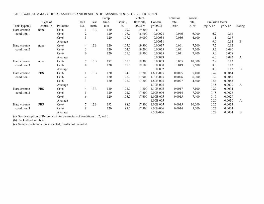
TABLE 4-10. SUMMARY OF PARAMETERS AND RESULTS OF EMISSION TESTS FOR REFERENCE 9.Samp. Volum. Emission Process
Type of Run Test time, Isokin., flow rate, Concen., rate, rate, Emission factorTank Type(a) control(b) Pollutant No. meth. min % DSCFM gr/DSCF lb/hr A-hr mg/A-hr gr/A-hr RatingHard chrome none Cr+6 1 13B 120 109.0 19,200 c condition 1 Cr+6 2 120 108.0 18,900 0.00028 0.046 6,000 6.9 0.11
Cr+6 3 120 107.0 19,000 0.00034 0.056 4,600 11 0.17Average 0.00031 9.0 0.14 B
Hard chrome none Cr+6 4 13B 120 105.0 19,300 0.00037 0.061 7,200 7.7 0.12 condition 2 Cr+6 5 120 104.0 19,200 0.00025 0.041 7,200 5.2 0.080
Cr+6 6 120 105.0 18,900 0.00025 0.041 7,400 5.0 0.078Average 0.00029 6.0 0.092 A
Hard chrome none Cr+6 7 13B 192 105.0 19,300 0.00033 0.055 10,000 7.9 0.12 condition 3 Cr+6 8 120 105.0 19,100 0.00030 0.049 5,600 8.0 0.12
Average 0.00032 8.0 0.12 BHard chrome PBS Cr+6 1 13B 120 104.0 17,700 1.60E-005 0.0025 5,400 0.42 0.0064 condition 1 Cr+6 2 120 102.0 17,900 1.70E-005 0.0026 6,000 0.39 0.0061
Cr+6 3 120 102.0 17,800 1.80E-005 0.0027 4,600 0.54 0.0083Average 1.70E-005 0.45 0.0070 A
Hard chrome PBS Cr+6 4 13B 120 102.0 1,800 1.10E-005 0.0017 7,100 0.22 0.0034 condition 2 Cr+6 5 120 102.0 17,600 9.00E-006 0.0014 7,200 0.18 0.0028
Cr+6 6 120 103.0 17,600 1.00E-005 0.0015 7,400 0.19 0.0029Average 1.00E-005 0.20 0.0030 A
Hard chrome PBS Cr+6 7 13B 192 98.0 17,800 1.00E-005 0.0015 10,000 0.22 0.0034 condition 3 Cr+6 8 120 97.0 17,900 9.00E-006 0.0014 5,600 0.22 0.0034
Average 9.50E-006 0.22 0.0034 B(a) See description of Reference 9 for parameters of conditions 1, 2, and 3.(b) Packed bed scrubber.(c) Sample contamination suspected, results not included.

4-55
TABLE 4-11. SUMMARY OF PARAMETERS AND RESULTS OF EMISSION TESTS FORREFERENCE 10
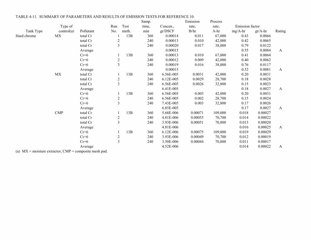
TABLE 4-11. SUMMARY OF PARAMETERS AND RESULTS OF EMISSION TESTS FOR REFERENCE 10.Samp. Emission Process
Type of Run Test time, Concen., rate, rate, Emission factorTank Type control(a) Pollutant No. meth. min gr/DSCF lb/hr A-hr mg/A-hr gr/A-hr Rating
Hard chrome MX total Cr 1 13B 360 0.00014 0.011 67,000 0.43 0.0066total Cr 2 240 0.00013 0.010 42,000 0.42 0.0065total Cr 3 240 0.00020 0.017 38,000 0.79 0.0122Average 0.00015 0.55 0.0084 ACr+6 1 13B 360 0.00013 0.010 67,000 0.41 0.0064Cr+6 2 240 0.00012 0.009 42,000 0.40 0.0062Cr+6 3 240 0.00019 0.016 38,000 0.76 0.0117Average 0.00015 0.52 0.0081 A
MX total Cr 1 13B 360 6.56E-005 0.0031 42,000 0.20 0.0031total Cr 2 240 6.12E-005 0.0029 28,700 0.18 0.0028total Cr 3 240 6.56E-005 0.0026 32,800 0.15 0.0023Average 6.41E-005 0.18 0.0027 ACr+6 1 13B 360 6.56E-005 0.003 42,000 0.20 0.0031Cr+6 2 240 6.56E-005 0.002 28,700 0.15 0.0024Cr+6 3 240 7.43E-005 0.003 32,800 0.17 0.0026Average 6.85E-005 0.17 0.0027 A
CMP total Cr 1 13B 360 5.68E-006 0.00071 109,000 0.018 0.00027total Cr 2 240 4.81E-006 0.00055 70,700 0.014 0.00022total Cr 3 240 3.93E-006 0.00051 70,800 0.013 0.00020Average 4.81E-006 0.016 0.00025 ACr+6 1 13B 360 6.12E-006 0.00075 109,000 0.019 0.00029Cr+6 2 240 3.93E-006 0.00049 70,700 0.012 0.00019Cr+6 3 240 3.50E-006 0.00044 70,800 0.011 0.00017Average 4.52E-006 0.014 0.00022 A
(a) MX = moisture extractor, CMP = composite mesh pad.

4-56
TABLE 4-12. AVERAGE OPERATING PARAMETERS MONITORED DURING EACH EMISSIONS TEST RUN
Run No.Operatingvoltage, V
Operatingcurrent, A
Temperature ofplating solution,
EC (EF)
1 6.4 6,800 141
2 6.4 6,800 141
3 6.4 6,800 141
4 6.3 6,800 140
5 7.2 10,110 144
6 7.2 10,200 143

4-57
TABLE 4-13. SUMMARY OF PARAMETERS AND RESULTS OF EMISSION TESTS FORREFERENCE 11

TABLE 4-13. SUMMARY OF PARAMETERS AND RESULTS OF EMISSION TESTS FOR REFERENCE 11.Samp. Emission Process
Type of Run Test time, Concen., rate, rate, Emission factorTank Type control(a) Pollutant No. meth. min gr/DSCF lb/hr A-hr mg/A-hr gr/A-hr RatingHard chrome none total Cr 1 13B 120 0.00042 0.092 13,600 6.1 0.095
total Cr 2 120 0.00046 0.10 13,600 6.9 0.11total Cr 3 120 0.00036 0.079 13,600 5.3 0.081Average 0.00042 6.1 0.094 A
CMP total Cr 1 13B 120 3.93E-006 0.00095 13,600 0.063 0.00098total Cr 2 120 5.24E-006 0.0012 13,600 0.083 0.0013total Cr 3 120 5.68E-006 0.0013 13,600 0.090 0.0014Average 4.95E-006 0.079 0.0012 A
FS total Cr 1 13B 120 7.43E-005 0.016 13,600 1.1 0.017total Cr 2 120 0.00026 0.058 20,200 2.6 0.040total Cr 3 120 0.00016 0.036 20,400 1.6 0.025Average 0.00016 1.8 0.027 A
FS/CMP total Cr 1 13B 120 2.19E-006 0.00053 13,600 0.035 0.00054total Cr 2 120 3.06E-006 0.00073 20,200 0.033 0.00050total Cr 3 120 5.24E-006 0.0013 20,400 0.056 0.00086Average 3.50E-006 0.041 0.00064 A
(a) FS = fume suppressant, CMP = composite mesh pad.

4-58
TABLE 4-14. DIMENSIONS AND OPERATING PARAMETERS FOR THE SEVEN HARD CHROMIUM PLATING TANKS
FOR REFERENCE 12
Tank No.Capacity, L
(gal)
Maximumrated voltage per
cell, V
Maximumrated current per
cell, A
1 11,360(3,000)
2 @ 15 10,000; 3,000
2 11,360(3,000)
2 @ 15 12,000; 3,000
3 6,060(1,600)
15 8,000
4 13,250(3,500)
15 16,000
5 4,000(1,060)
15 8,000
6 17,790(4,700)
2 @ 15 2 @ 12,000
7a 21,580(5,700)
2 @ 15 2 @ 12,000
aPlating tank was not operated during the emission test.

4-59
TABLE 4-15. SUMMARY OF PARAMETERS AND RESULTS OF EMISSION TESTS FORREFERENCE 12

TABLE 4-15. SUMMARY OF PARAMETERS AND RESULTS OF EMISSION TESTS FOR REFERENCE 12.Samp. Gas Volum. Emission Process
Type of Run Test time, Isokin., volume, flow rate, Mass, Concen., rate, rate, Emission factorTank Type control(a) Pollutant No. meth. min % DSCF DSCFM ug gr/DSCF lb/hr A-hr mg/A-hr gr/A-hr RatingHard chrome none total Cr 1 13B 360 98.1 606.46 22,204 1,347,000 0.0343 6.5235 366,530 48 0.75
total Cr 2 360 96.9 602.13 22,285 982,900 0.0252 4.8119 361,850 36 0.56total Cr 3 360 91.4 610.94 23,144 1,248,033 0.0315 6.2538 139,090 122 1.9Average 0.0303 69 1.1 ACr+6 1 13B 360 98.1 606.46 22,204 1,399,850 0.0356 6.7795 366,530 50 0.78Cr+6 2 360 96.9 602.13 22,285 1,065,100 0.0273 5.2144 361,850 39 0.61Cr+6 3 360 91.4 610.94 23,144 1,350,030 0.0341 6.7649 139,090 132 2.0Average 0.0323 74 1.1 A
PBS/CMP total Cr 1 13B 375 99.0 265.26 24,013 47.0 2.73E-006 0.00056 381,430 0.0042 6.5E-005total Cr 2 375 98.9 261.24 23,674 25.5 1.51E-006 0.00031 376,200 0.0023 3.6E-005total Cr 3 375 99.8 271.47 24,381 65.5 3.72E-006 0.00078 366,740 0.0060 9.3E-005Average 2.65E-006 0.0042 6.4E-005 ACr+6 1 13B 375.0 99.0 265.3 24,013 43.3 2.52E-006 0.00052 381,430 0.0039 5.9E-005Cr+6 2 375.0 98.9 261.2 23,674 25.5 1.51E-006 0.00031 376,200 0.0023 3.6E-005Cr+6 3 375.0 99.8 271.5 24,381 66.8 3.80E-006 0.00079 366,740 0.0061 9.5E-005Average 2.61E-006 0.0041 6.3E-005 A
(a) PBS = packed bed scrubber; CMP = composite mesh pad.

4-60
TABLE 4-16. SUMMARY OF PARAMETERS AND RESULTS OF EMISSION TESTS FORREFERENCE 13

TABLE 4-16. SUMMARY OF PARAMETERS AND RESULTS OF EMISSION TEST FOR REFERENCE 13. Samp. Gas Volum. Emission Process
Type of Run Test time, Isokin., volume, flow rate, Mass, Concen., rate, rate, Emission factorTank Type control Pollutant No. meth. min % DSCF DSCFM ug gr/DSCF lb/hr A-hr mg/A-hr gr/A-hr RatingHard chrome none total Cr 1 13B 120 99.3 91.32 11,268 7,500 0.0013 0.122 17,590 6.3 0.097
total Cr 2 120 98.1 94.29 11,779 7,500 0.0012 0.124 28,520 3.9 0.061total Cr 3 120 100.6 90.57 11,027 13,600 0.0023 0.219 11,361 17 0.27total Cr 4 120 101.6 91.05 11,034 5,000 0.00085 0.0802 21,652 3.4 0.052total Cr 5 120 101.3 90.52 11,191 2,250 0.00038 0.0368 20,733 1.6 0.025total Cr 6 120 102.7 86.84 10,361 4,750 0.00084 0.0750 20,373 3.3 0.052Average 0.00115 6.0 0.093 ACr+6 1 13B 120 99.3 91.32 11,268 5,142 0.00087 0.084 17,590 4.3 0.067Cr+6 2 120 98.1 94.29 11,779 6,262 0.00102 0.103 28,520 3.3 0.051Cr+6 3 120 100.6 90.57 11,027 9,688 0.00165 0.156 11,361 12.5 0.19Cr+6 4 120 101.6 91.05 11,034 4,483 0.00076 0.072 21,652 3.0 0.046Cr+6 5 120 101.3 90.52 11,191 2,082 0.00035 0.034 20,733 1.5 0.023Cr+6 6 120 102.7 86.84 10,361 3,968 0.00071 0.063 20,373 2.8 0.043Average 0.00089 4.6 0.070 A

4-61
TABLE 4-17. SUMMARY OF PARAMETERS AND RESULTS OF EMISSION TESTS FORREFERENCE 14
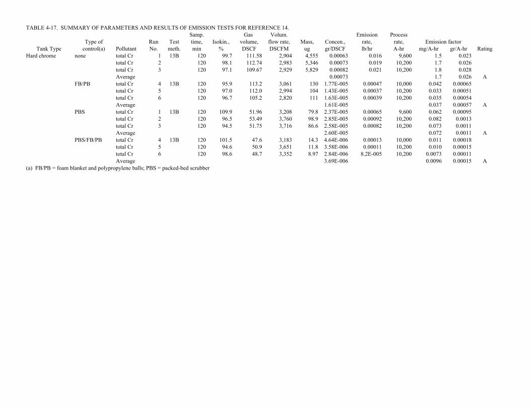
TABLE 4-17. SUMMARY OF PARAMETERS AND RESULTS OF EMISSION TESTS FOR REFERENCE 14.Samp. Gas Volum. Emission Process
Type of Run Test time, Isokin., volume, flow rate, Mass, Concen., rate, rate, Emission factorTank Type control(a) Pollutant No. meth. min % DSCF DSCFM ug gr/DSCF lb/hr A-hr mg/A-hr gr/A-hr Rating
Hard chrome none total Cr 1 13B 120 99.7 111.58 2,904 4,555 0.00063 0.016 9,600 1.5 0.023total Cr 2 120 98.1 112.74 2,983 5,346 0.00073 0.019 10,200 1.7 0.026total Cr 3 120 97.1 109.67 2,929 5,829 0.00082 0.021 10,200 1.8 0.028Average 0.00073 1.7 0.026 A
FB/PB total Cr 4 13B 120 95.9 113.2 3,061 130 1.77E-005 0.00047 10,000 0.042 0.00065total Cr 5 120 97.0 112.0 2,994 104 1.43E-005 0.00037 10,200 0.033 0.00051total Cr 6 120 96.7 105.2 2,820 111 1.63E-005 0.00039 10,200 0.035 0.00054Average 1.61E-005 0.037 0.00057 A
PBS total Cr 1 13B 120 109.9 51.96 3,208 79.8 2.37E-005 0.00065 9,600 0.062 0.00095total Cr 2 120 96.5 53.49 3,760 98.9 2.85E-005 0.00092 10,200 0.082 0.0013total Cr 3 120 94.5 51.75 3,716 86.6 2.58E-005 0.00082 10,200 0.073 0.0011Average 2.60E-005 0.072 0.0011 A
PBS/FB/PB total Cr 4 13B 120 101.5 47.6 3,183 14.3 4.64E-006 0.00013 10,000 0.011 0.00018total Cr 5 120 94.6 50.9 3,651 11.8 3.58E-006 0.00011 10,200 0.010 0.00015total Cr 6 120 98.6 48.7 3,352 8.97 2.84E-006 8.2E-005 10,200 0.0073 0.00011Average 3.69E-006 0.0096 0.00015 A
(a) FB/PB = foam blanket and polypropylene balls; PBS = packed-bed scrubber

4-62
TABLE 4-18. SUMMARY OF PARAMETERS AND RESULTS OF EMISSION TESTS FORREFERENCE 15

TABLE 4-18. SUMMARY OF PARAMETERS AND RESULTS OF EMISSION TESTS FOR REFERENCE 15.Samp. Volum. Emission Process
Type of Run Test time, Isokin., flow rate, Concen., rate, rate, Emission factorTank Type control Pollutant No. meth. min % DSCFM gr/DSCF lb/hr A-hr mg/A-hr gr/A-hr RatingDecorative Chrome none total Cr 1 13B 180 98.0 22,600 0.00072 0.14 97,400 2.0 0.030
total Cr 2 180 98.5 23,200 0.00053 0.11 104,000 1.4 0.021total Cr 3 180 98.3 23,200 0.00063 0.13 89,600 1.9 0.030Average 0.00063 1.7 0.027 A
none Cr+6 1 13B 180 98.0 22,600 0.00085 0.17 97,400 2.3 0.036Cr+6 2 180 98.5 23,200 0.00056 0.11 104,000 1.5 0.023Cr+6 3 180 98.3 23,200 0.00067 0.13 89,600 2.0 0.031Average 0.00070 1.9 0.030 A

4-63
TABLE 4-19. SUMMARY OF PARAMETERS AND RESULTS OF EMISSION TESTS FORREFERENCE 16
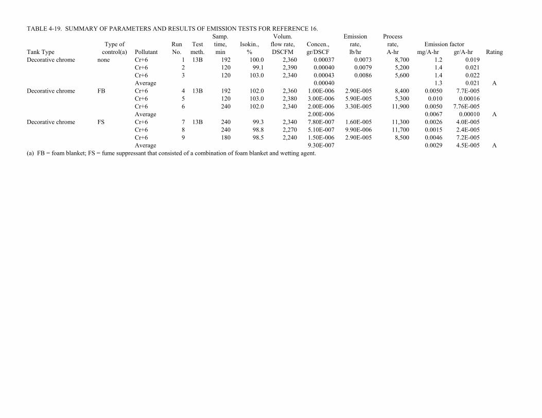
TABLE 4-19. SUMMARY OF PARAMETERS AND RESULTS OF EMISSION TESTS FOR REFERENCE 16.Samp. Volum. Emission Process
Type of Run Test time, Isokin., flow rate, Concen., rate, rate, Emission factorTank Type control(a) Pollutant No. meth. min % DSCFM gr/DSCF lb/hr A-hr mg/A-hr gr/A-hr RatingDecorative chrome none Cr+6 1 13B 192 100.0 2,360 0.00037 0.0073 8,700 1.2 0.019
Cr+6 2 120 99.1 2,390 0.00040 0.0079 5,200 1.4 0.021Cr+6 3 120 103.0 2,340 0.00043 0.0086 5,600 1.4 0.022Average 0.00040 1.3 0.021 A
Decorative chrome FB Cr+6 4 13B 192 102.0 2,360 1.00E-006 2.90E-005 8,400 0.0050 7.7E-005Cr+6 5 120 103.0 2,380 3.00E-006 5.90E-005 5,300 0.010 0.00016Cr+6 6 240 102.0 2,340 2.00E-006 3.30E-005 11,900 0.0050 7.76E-005Average 2.00E-006 0.0067 0.00010 A
Decorative chrome FS Cr+6 7 13B 240 99.3 2,340 7.80E-007 1.60E-005 11,300 0.0026 4.0E-005Cr+6 8 240 98.8 2,270 5.10E-007 9.90E-006 11,700 0.0015 2.4E-005Cr+6 9 180 98.5 2,240 1.50E-006 2.90E-005 8,500 0.0046 7.2E-005Average 9.30E-007 0.0029 4.5E-005 A
(a) FB = foam blanket; FS = fume suppressant that consisted of a combination of foam blanket and wetting agent.

4-64
TABLE 4-20. SUMMARY OF PARAMETERS AND RESULTS OF EMISSION TESTS FORREFERENCE 17
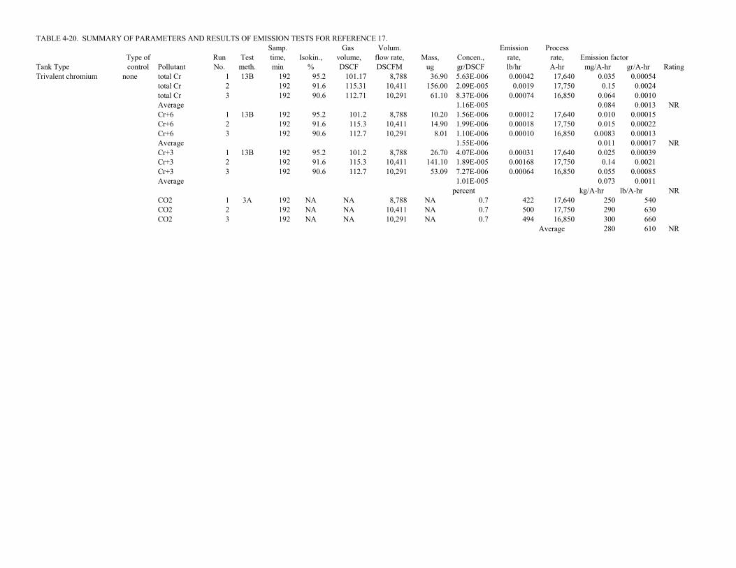
TABLE 4-20. SUMMARY OF PARAMETERS AND RESULTS OF EMISSION TESTS FOR REFERENCE 17.Samp. Gas Volum. Emission Process
Type of Run Test time, Isokin., volume, flow rate, Mass, Concen., rate, rate, Emission factorTank Type control Pollutant No. meth. min % DSCF DSCFM ug gr/DSCF lb/hr A-hr mg/A-hr gr/A-hr RatingTrivalent chromium none total Cr 1 13B 192 95.2 101.17 8,788 36.90 5.63E-006 0.00042 17,640 0.035 0.00054
total Cr 2 192 91.6 115.31 10,411 156.00 2.09E-005 0.0019 17,750 0.15 0.0024total Cr 3 192 90.6 112.71 10,291 61.10 8.37E-006 0.00074 16,850 0.064 0.0010Average 1.16E-005 0.084 0.0013 NRCr+6 1 13B 192 95.2 101.2 8,788 10.20 1.56E-006 0.00012 17,640 0.010 0.00015Cr+6 2 192 91.6 115.3 10,411 14.90 1.99E-006 0.00018 17,750 0.015 0.00022Cr+6 3 192 90.6 112.7 10,291 8.01 1.10E-006 0.00010 16,850 0.0083 0.00013Average 1.55E-006 0.011 0.00017 NRCr+3 1 13B 192 95.2 101.2 8,788 26.70 4.07E-006 0.00031 17,640 0.025 0.00039Cr+3 2 192 91.6 115.3 10,411 141.10 1.89E-005 0.00168 17,750 0.14 0.0021Cr+3 3 192 90.6 112.7 10,291 53.09 7.27E-006 0.00064 16,850 0.055 0.00085Average 1.01E-005 0.073 0.0011
percent kg/A-hr lb/A-hr NRCO2 1 3A 192 NA NA 8,788 NA 0.7 422 17,640 250 540CO2 2 192 NA NA 10,411 NA 0.7 500 17,750 290 630CO2 3 192 NA NA 10,291 NA 0.7 494 16,850 300 660
Average 280 610 NR

4-65
TABLE 4-21. SUMMARY OF PARAMETERS AND RESULTS OF EMISSION TESTS FORREFERENCE 19

TABLE 4-21. SUMMARY OF PARAMETERS AND RESULTS OF EMISSION TESTS FOR REFERENCE 19.Samp. Gas Volum. Emission Process
Type of Run Test time, Isokin., volume, flow rate, Mass, Concen., rate, rate, Emission factor(b)Tank Type control(a) Pollutant No. meth. min % DSCF DSCFM ug gr/DSCF lb/hr ft g/hr-m2 gr/hr-ft2 RatingChromic acid none total Cr 1 CARB 180 105.2 113.19 7,372 177.90 2.43E-005 0.0015 NRanodizing 425
PPB total Cr 1 CARB 240 95.2 262.5 11,854 4.60 2.70E-007 2.7E-005 NR425
PPB and total Cr 2 CARB 360 98.5 340.6 11,909 1.50 6.80E-008AM total Cr 3 425 360 93.8 406.6 11,575 2.90 1.10E-007Average 8.90E-008 NR
(a) PPB = polypropylene balls; AM = antimisting agent.(b) Tank dimensions not provided; emission factors cannot be calculated.

4-66
TABLE 4-22. SUMMARY OF PARAMETERS AND RESULTS OF EMISSION TESTS FORREFERENCE 20
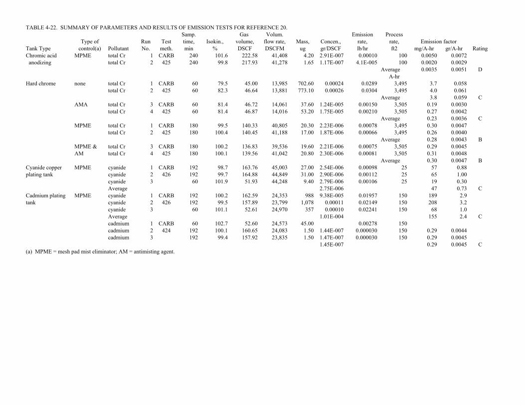
TABLE 4-22. SUMMARY OF PARAMETERS AND RESULTS OF EMISSION TESTS FOR REFERENCE 20.Samp. Gas Volum. Emission Process
Type of Run Test time, Isokin., volume, flow rate, Mass, Concen., rate, rate, Emission factorTank Type control(a) Pollutant No. meth. min % DSCF DSCFM ug gr/DSCF lb/hr ft2 mg/A-hr gr/A-hr RatingChromic acid MPME total Cr 1 CARB 240 101.6 222.58 41,408 4.20 2.91E-007 0.00010 100 0.0050 0.0072 anodizing total Cr 2 425 240 99.8 217.93 41,278 1.65 1.17E-007 4.1E-005 100 0.0020 0.0029
Average 0.0035 0.0051 DA-hr
Hard chrome none total Cr 1 CARB 60 79.5 45.00 13,985 702.60 0.00024 0.0289 3,495 3.7 0.058total Cr 2 425 60 82.3 46.64 13,881 773.10 0.00026 0.0304 3,495 4.0 0.061
Average 3.8 0.059 CAMA total Cr 3 CARB 60 81.4 46.72 14,061 37.60 1.24E-005 0.00150 3,505 0.19 0.0030
total Cr 4 425 60 81.4 46.87 14,016 53.20 1.75E-005 0.00210 3,505 0.27 0.0042Average 0.23 0.0036 C
MPME total Cr 1 CARB 180 99.5 140.33 40,805 20.30 2.23E-006 0.00078 3,495 0.30 0.0047total Cr 2 425 180 100.4 140.45 41,188 17.00 1.87E-006 0.00066 3,495 0.26 0.0040
Average 0.28 0.0043 BMPME & total Cr 3 CARB 180 100.2 136.83 39,536 19.60 2.21E-006 0.00075 3,505 0.29 0.0045AM total Cr 4 425 180 100.1 139.56 41,042 20.80 2.30E-006 0.00081 3,505 0.31 0.0048
Average 0.30 0.0047 BCyanide copper MPME cyanide 1 CARB 192 98.7 163.76 45,003 27.00 2.54E-006 0.00098 25 57 0.88plating tank cyanide 2 426 192 99.7 164.88 44,849 31.00 2.90E-006 0.00112 25 65 1.00
cyanide 3 60 101.9 51.93 44,248 9.40 2.79E-006 0.00106 25 19 0.30Average 2.75E-006 47 0.73 C
Cadmium plating MPME cyanide 1 CARB 192 100.2 162.59 24,353 988 9.38E-005 0.01957 150 189 2.9tank cyanide 2 426 192 99.5 157.89 23,799 1,078 0.00011 0.02149 150 208 3.2
cyanide 3 60 101.1 52.61 24,970 357 0.00010 0.02241 150 68 1.0Average 1.01E-004 155 2.4 Ccadmium 1 CARB 60 102.7 52.60 24,573 45.00 0.00278 150cadmium 2 424 192 100.1 160.65 24,083 1.50 1.44E-007 0.000030 150 0.29 0.0044cadmium 3 192 99.4 157.92 23,835 1.50 1.47E-007 0.000030 150 0.29 0.0045
1.45E-007 0.29 0.0045 C(a) MPME = mesh pad mist eliminator; AM = antimisting agent.

4-67
TABLE 4-23. SUMMARY OF PARAMETERS AND RESULTS OF EMISSION TESTS FORREFERENCE 21
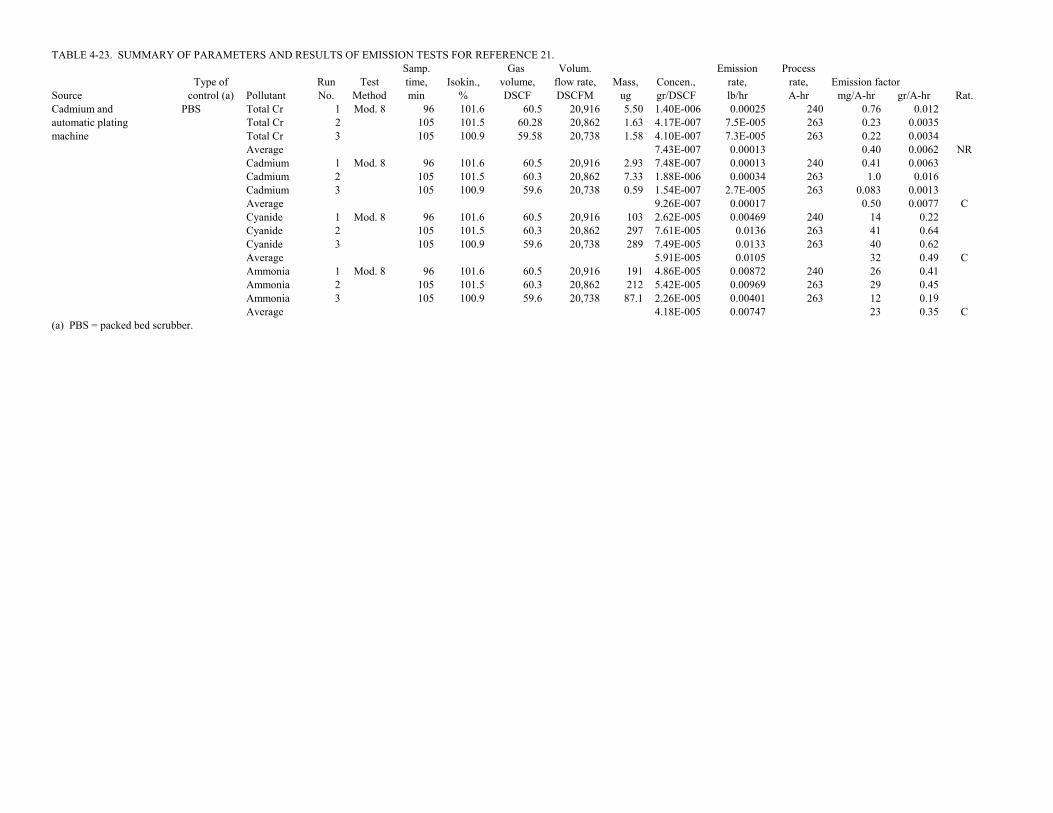
TABLE 4-23. SUMMARY OF PARAMETERS AND RESULTS OF EMISSION TESTS FOR REFERENCE 21.Samp. Gas Volum. Emission Process
Type of Run Test time, Isokin., volume, flow rate, Mass, Concen., rate, rate, Emission factorSource control (a) Pollutant No. Method min % DSCF DSCFM ug gr/DSCF lb/hr A-hr mg/A-hr gr/A-hr Rat.Cadmium and PBS Total Cr 1 Mod. 8 96 101.6 60.5 20,916 5.50 1.40E-006 0.00025 240 0.76 0.012automatic plating Total Cr 2 105 101.5 60.28 20,862 1.63 4.17E-007 7.5E-005 263 0.23 0.0035machine Total Cr 3 105 100.9 59.58 20,738 1.58 4.10E-007 7.3E-005 263 0.22 0.0034
Average 7.43E-007 0.00013 0.40 0.0062 NRCadmium 1 Mod. 8 96 101.6 60.5 20,916 2.93 7.48E-007 0.00013 240 0.41 0.0063Cadmium 2 105 101.5 60.3 20,862 7.33 1.88E-006 0.00034 263 1.0 0.016Cadmium 3 105 100.9 59.6 20,738 0.59 1.54E-007 2.7E-005 263 0.083 0.0013Average 9.26E-007 0.00017 0.50 0.0077 CCyanide 1 Mod. 8 96 101.6 60.5 20,916 103 2.62E-005 0.00469 240 14 0.22Cyanide 2 105 101.5 60.3 20,862 297 7.61E-005 0.0136 263 41 0.64Cyanide 3 105 100.9 59.6 20,738 289 7.49E-005 0.0133 263 40 0.62Average 5.91E-005 0.0105 32 0.49 CAmmonia 1 Mod. 8 96 101.6 60.5 20,916 191 4.86E-005 0.00872 240 26 0.41Ammonia 2 105 101.5 60.3 20,862 212 5.42E-005 0.00969 263 29 0.45Ammonia 3 105 100.9 59.6 20,738 87.1 2.26E-005 0.00401 263 12 0.19Average 4.18E-005 0.00747 23 0.35 C
(a) PBS = packed bed scrubber.

4-68
TABLE 4-24. SUMMARY OF PARAMETERS AND RESULTS OF EMISSION TESTS FORREFERENCE 22

TABLE 4-24. SUMMARY OF PARAMETERS AND RESULTS OF EMISSION TESTS FOR REFERENCE 22.Samp. Gas Volum. Emission Process
Type of Run Test time, Isokin., volume, flow rate, Mass, Concen., rate, rate, Emission factorTank Type control(a) Pollutant No. meth. min % DSCF DSCFM ug gr/DSCF lb/hr A-hr mg/A-hr gr/A-hr RatingHard chrome None total Cr 1 CARB 120 93.0 96.31 12,400 9.1 1.5E-006 0.00015 853 0.16 0.0025
total Cr 2 425 120 93.0 96.73 12,468 6.2 9.9E-007 0.00011 700 0.14 0.0021Average 1.2E-006 0.15 0.0023 D
PBS total Cr 1 CARB 120 102.0 94.3 13,198 6.9 1.1E-006 0.00013 853 0.14 0.0021total Cr 2 425 120 101.0 94.0 13,252 6.0 9.8E-007 0.00011 700 0.14 0.0022Average 1.1E-006 0.14 0.0022 D
(a) PBS = packed bed scrubber.

4-69
TABLE 4-25. SUMMARY OF PARAMETERS AND RESULTS OF EMISSION TESTS FORREFERENCE 23

TABLE 4-25. SUMMARY OF PARAMETERS AND RESULTS OF EMISSION TESTS FOR REFERENCE 23.Samp. Gas Volum. Emission Process
Type of Run Test time, Isokin., volume, flow rate, Mass, Concen., rate, rate, Emission factorTank Type control(a) Pollutant No. meth. min % DSCF DSCFM ug gr/DSCF lb/hr A-hr mg/A-hr gr/A-hr RatingHard chrome None Cr+6 1 CARB 240 91.0 153.96 29,484 5530.0 0.00055 0.14 51,260 5.0 0.077 Line L Cr+6 2 425 240 94.0 161.80 29,986 5600.0 0.00053 0.14 47,323 5.3 0.081
Average 0.00054 5.1 0.079 Dtotal Cr 1 CARB 240 91.0 153.96 29,484 6860.0 0.00069 0.17 51,260 6.2 0.095total Cr 2 425 240 94.0 161.80 29,986 5960.0 0.00057 0.15 47,323 5.6 0.086Average 0.00063 5.9 0.091 D
PBS Cr+6 1 CARB 240 101.0 184.89 35,209 7.0 5.84E-007 51,260Cr+6 2 425 240 99.0 171.9 34,331 1.0 8.98E-008 47,323Average 3.37E-007total Cr 1 CARB 240 101.0 184.9 35,209 19.0 1.59E-006 0.00048 51,260 0.017 0.00026total Cr 2 425 240 99.0 171.87 34,331 3.0 2.69E-007 47,323Average 9.28E-007 0.017 0.00026 NR
Hard chrome None Cr+6 1 CARB 240 92.0 186.72 20,466 15,174 0.00125 0.22 29,774 13 0.21 Line M Cr+6 2 425 240 94.0 198.28 21,018 5,520 0.00043 0.077 33,376 4.2 0.065
Average 0.00084 8.8 0.14 Dtotal Cr 1 CARB 240 92.0 186.72 20,466 10,470 0.00087 0.15 29,774 9.3 0.14total Cr 2 425 240 94.0 198.28 21,018 6,277 0.00049 0.088 33,376 4.8 0.074Average 0.00068 7.0 0.108 D
PBS Cr+6 1 CARB 240 103.0 185.52 25,071 2.5 2.08E-007 29,774Cr+6 2 425 240 99.0 166.6 21,988 3.4 3.15E-007 33,376Average 2.61E-007total Cr 1 CARB 240 103.0 185.5 25,071 5.0 4.16E-007 8.9E-005 29,774 0.0054 8.4E-005total Cr 2 425 240 99.0 166.57 21,988 39.0 3.61E-006 0.00068 29,774 0.041 0.00064Average 2.01E-006 0.023 0.00036 D
(a) PBS = packed bed scrubber.

4-70
TABLE 4-26. SUMMARY OF PARAMETERS AND RESULTS OF EMISSION TESTS FORREFERENCE 24
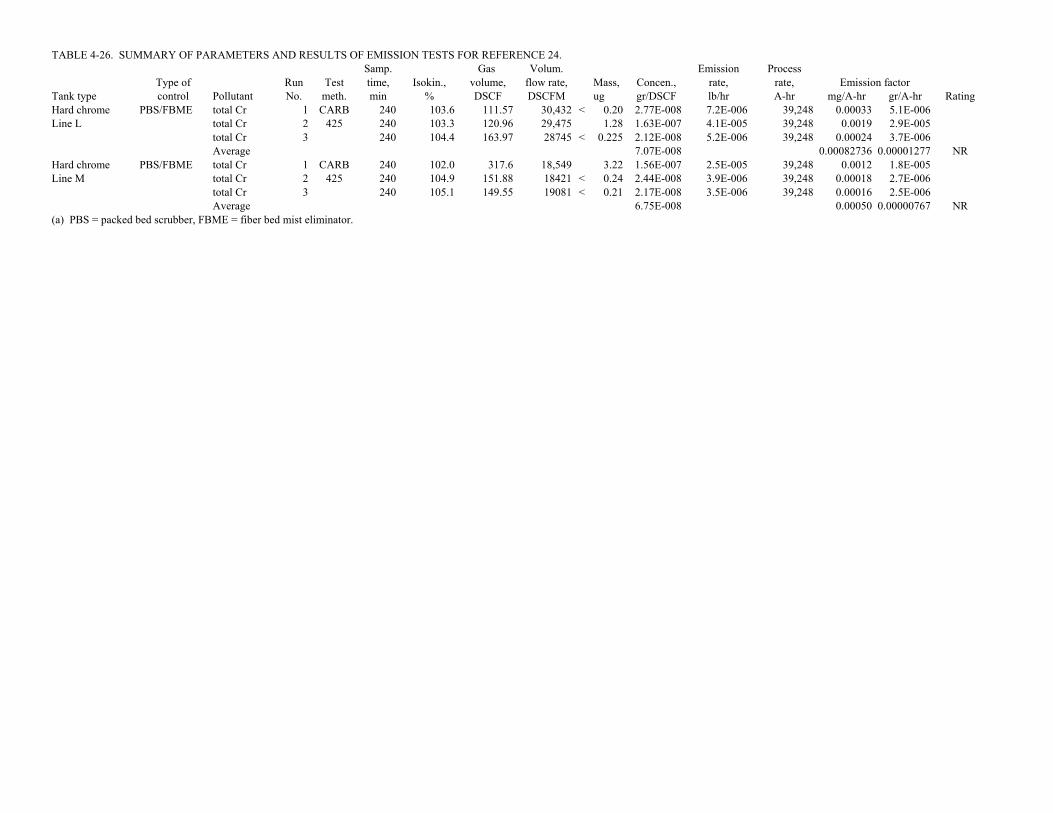
TABLE 4-26. SUMMARY OF PARAMETERS AND RESULTS OF EMISSION TESTS FOR REFERENCE 24.Samp. Gas Volum. Emission Process
Type of Run Test time, Isokin., volume, flow rate, Mass, Concen., rate, rate, Emission factorTank type control Pollutant No. meth. min % DSCF DSCFM ug gr/DSCF lb/hr A-hr mg/A-hr gr/A-hr RatingHard chrome PBS/FBME total Cr 1 CARB 240 103.6 111.57 30,432 < 0.20 2.77E-008 7.2E-006 39,248 0.00033 5.1E-006Line L total Cr 2 425 240 103.3 120.96 29,475 1.28 1.63E-007 4.1E-005 39,248 0.0019 2.9E-005
total Cr 3 240 104.4 163.97 28745 < 0.225 2.12E-008 5.2E-006 39,248 0.00024 3.7E-006Average 7.07E-008 0.00082736 0.00001277 NR
Hard chrome PBS/FBME total Cr 1 CARB 240 102.0 317.6 18,549 3.22 1.56E-007 2.5E-005 39,248 0.0012 1.8E-005Line M total Cr 2 425 240 104.9 151.88 18421 < 0.24 2.44E-008 3.9E-006 39,248 0.00018 2.7E-006
total Cr 3 240 105.1 149.55 19081 < 0.21 2.17E-008 3.5E-006 39,248 0.00016 2.5E-006Average 6.75E-008 0.00050 0.00000767 NR
(a) PBS = packed bed scrubber, FBME = fiber bed mist eliminator.

4-71
TABLE 4-27. SUMMARY OF PARAMETERS AND RESULTS OF EMISSION TESTS FORREFERENCE 25

TABLE 4-27. SUMMARY OF PARAMETERS AND RESULTS OF EMISSION TESTS FOR REFERENCE 25.Samp. Gas Volum. Emission Process
Type of Run Test time, Isokin., volume, flow rate, Mass, Concen., rate, rate, Emission factorTank type control(a) Pollutant No. meth. min % DSCF DSCFM ug gr/DSCF lb/hr A-hr mg/A-hr gr/A-hr RatingHard chrome none total Cr 1 CARB 60 101.0 68.53 1,664 3552.70 0.00080 0.01141 807 6.4 0.10
total Cr 2 425 60 103.3 44.50 1,564 3795.20 0.00132 0.01764 820 9.8 0.15Average 0.00106 8.1 0.12Cr+6 1 CARB 60 101.0 68.5 1,664 2627.20 0.00059 0.00844 807 4.7 0.073Cr+6 2 425 60 103.3 44.5 1,564 2917.00 0.00101 0.01356 820 7.5 0.12Average 0.00080 6.1 0.094total Cr 1 CARB 60 102.8 45.93 1,633 3423.40 0.00115 0.01610 1,633 4.5 0.069total Cr 2 425 60 102.1 45.97 1,634 8526.00 0.00286 0.04009 1,525 12 0.18Average 0.00201 8.2 0.13Cr+6 1 CARB 60 102.8 45.9 1,633 2675.20 0.00090 0.01258 1,633 3.5 0.054Cr+6 2 425 60 102.1 46.0 1,634 8379.60 0.00281 0.03940 1,525 12 0.18Average 0.00186 7.6 0.12total Cr 1 CARB 60 101.9 45.78 1,631 5194.10 0.00175 0.02448 2,473 4.5 0.069total Cr 2 425 60 97.3 68.89 1,690 8886.20 0.00199 0.02883 2,448 5.3 0.082Average 0.00187 4.9 0.076Cr+6 1 CARB 60 101.9 45.8 1,631 4818.60 0.00162 0.02271 2,473 4.2 0.064Cr+6 2 425 60 97.3 68.9 1,690 7123.10 0.00160 0.02311 2,448 4.3 0.066Average 0.00161 4.2 0.065
Overall Total Cr Average 0.00164 7.1 0.11 Aaverage Cr+6 Average 0.00142 6.0 0.092 A
FS/PB total Cr 1 CARB 60 99.6 46.37 1,689 114.07 3.80E-005 0.00055 845 0.30 0.0046total Cr 2 425 60 101.3 45.20 1,631 81.46 2.78E-005 0.00039 846 0.21 0.0032Average 3.29E-005 0.25 0.0039Cr+6 1 CARB 60 99.6 46.4 1,689 100.70 3.35E-005 0.00049 845 0.26 0.0040Cr+6 2 425 60 101.3 45.2 1,631 56.40 1.93E-005 0.00027 846 0.14 0.0022Average 2.64E-005 0.20 0.0031total Cr 1 CARB 60 102.2 46.16 1,639 126.74 4.24E-005 0.00060 1,671 0.16 0.0025total Cr 2 425 60 106.7 49.07 1,674 102.24 3.22E-005 0.00046 1,670 0.13 0.0019Average 3.73E-005 0.14 0.0022Cr+6 1 CARB 60 102.2 46.2 1,639 111.80 3.74E-005 0.00053 1,671 0.14 0.0022Cr+6 2 425 60 106.7 49.1 1,674 82.00 2.58E-005 0.00037 1,670 0.10 0.0016Average 3.16E-005 0.12 0.0019total Cr 1 CARB 60 100.3 46.03 1,677 201.36 6.75E-005 0.00097 2,472 0.18 0.0027total Cr 2 425 60 97.3 44.54 1,663 196.56 6.81E-005 0.00097 2,440 0.18 0.0028Average 6.78E-005 0.18 0.0028Cr+6 1 CARB 60 100.3 46.0 1,677 158.00 5.30E-005 0.00076 2,472 0.14 0.0022Cr+6 2 425 60 97.3 44.5 1,663 161.20 5.59E-005 0.00080 2,440 0.15 0.0023Average 5.44E-005 0.14 0.0022
Overall Total Cr Average 4.60E-005 0.19 0.0030 Aaverage Cr+6 Average 3.75E-005 0.16 0.0024 A
(a) FS/PB = combination of fume suppressant and polypropylene balls.

4-73
TABLE 4-28. SUMMARY OF PARAMETERS AND RESULTS OF EMISSION TESTS FORREFERENCE 26

TABLE 4-28. SUMMARY OF PARAMETERS AND RESULTS OF EMISSION TESTS FOR REFERENCE 26.Samp. Gas Volum. Emission Process
Type of Run Test time, Isokin., volume, flow rate, Mass, Concen., rate, rate, Emission factorTank type control(a) Pollutant No. meth. min % DSCF DSCFM ug gr/DSCF lb/hr A-hr mg/A-hr gr/A-hr RatingHard chrome none total Cr 1 CARB 60 97.5 46.16 1,731 1,568 0.00052 0.0078 853 4.1 0.064
total Cr 2 425 60 101.5 45.60 1,631 4,357 0.00147 0.0206 833 11 0.17Average 0.00100 7.7 0.12Cr+6 1 CARB 60 97.5 46.2 1,731 1,461 0.00049 0.0072 853 3.9 0.059Cr+6 2 425 60 101.5 45.6 1,631 3,944 0.00133 0.0187 833 10 0.16Average 0.00091 7.0 0.11total Cr 1 CARB 60 98.3 46.71 1,724 5,540 0.00183 0.0270 1,584 7.7 0.12total Cr 2 425 60 97.8 45.90 1,703 8,225 0.00277 0.0404 1,645 11 0.17Average 0.00230 9.4 0.15Cr+6 1 CARB 60 98.3 46.7 1,724 4,632 0.00153 0.0226 1,584 6.5 0.10Cr+6 2 425 60 97.8 45.9 1,703 8,087 0.00272 0.0397 1,645 11 0.17Average 0.00212 8.7 0.13total Cr 1CARB 425 60 100.2 45.92 1,664 2,691 0.00090 0.0129 2,568 2.3 0.035total Cr 2 60 98.3 45.61 1,695 9,370 0.00317 0.0461 2,504 8.3 0.13Average 0.00204 5.3 0.082Cr+6 1 CARB 60 100.2 45.9 1,664 2,401 0.00081 0.0115 2,568 2.0 0.031Cr+6 2 425 60 98.3 45.6 1,695 10,175 0.00344 0.0500 2,504 9.1 0.14Average 0.00212 5.5 0.086
Overall Total Cr Average 0.00178 7.5 0.12 Aaverage Cr+6 Average 0.00172 7.1 0.11 A
FS/PB total Cr 1 CARB 60 100.6 46.44 1,676 61.10 2.03E-005 0.000292 853 0.16 0.0024total Cr 2 425 60 101.8 46.80 1,680 21.40 7.06E-006 0.000102 855 0.054 0.00083Average 1.37E-005 0.10 0.0016Cr+6 1 CARB 60 100.6 46.4 1,676 56.70 1.88E-005 0.000271 853 0.14 0.0022Cr+6 2 425 60 101.8 46.8 1,680Average 1.88E-005 0.144 0.0022total Cr 1 CARB 60 100.0 45.89 1,695 127.00 4.27E-005 0.000620 1,654 0.17 0.0026total Cr 2 425 60 99.4 46.82 1,720 61.90 2.04E-005 0.000301 1,755 0.078 0.0012Average 3.16E-005 0.12 0.0019Cr+6 1 CARB 60 100.0 45.9 1,695 80.40 2.70E-005 0.000393 1,654 0.11 0.0017Cr+6 2 425 60 99.4 46.8 1,720 68.20 2.25E-005 0.000331 1,755 0.086 0.0013Average 2.48E-005 0.10 0.0015total Cr 1 CARB 60 98.2 45.48 1,663 121.90 4.14E-005 0.000590 2,560 0.10 0.0016total Cr 2 425 60 99.5 44.35 1,620 112.30 3.91E-005 0.000543 2,405 0.10 0.0016Average 4.02E-005 0.10 0.0016Cr+6 1 CARB 60 98.2 45.5 1,663 122.80 4.17E-005 0.000594 2,560 0.11 0.0016Cr+6 2 425 60 99.5 44.3 1,620 108.40 3.77E-005 0.000524 2,405 0.10 0.0015Average 3.97E-005 0.10 0.0016
Overall Total Cr Average 2.85E-005 0.11 0.0017 Aaverage Cr+6 Average 2.95E-005 0.11 0.0017 A
(a) FS/PB = combination of fume suppressant and polypropylene balls.

4-75
TABLE 4-29. SUMMARY OF PARAMETERS AND RESULTS OF EMISSION TESTS FORREFERENCE 27

TABLE 4-29. SUMMARY OF PARAMETERS AND RESULTS OF EMISSION TESTS FOR REFERENCE 27.Samp. Gas Volum. Emission Process
Type of Run Test time, Isokin., volume, flow rate, Mass, Concen., rate, rate, Emission factorTank type control(a) Pollutant No. meth. min % DSCF DSCFM ug gr/DSCF lb/hr A-hr mg/A-hr gr/A-hr RatingDecorative chrome none total Cr 1 CARB 60 108.1 108.07 2,697 1,395 0.00020 0.0046 328 6.4 0.098
total Cr 2 425 60 109.2 103.21 2,577 1,091 0.00016 0.0036 328 5.0 0.077Average 0.00018 5.7 0.088Cr+6 1 CARB 60 108.1 108.1 2,697 963 0.00014 0.0032 328 4.4 0.068Cr+6 2 425 60 109.2 103.2 2,577 909 0.00014 0.0030 328 4.2 0.064Average 0.00014 4.3 0.066total Cr 1 CARB 60 108.0 118.39 2,623 1,693 0.00022 0.0050 454 5.0 0.076total Cr 2 60 113.8 110.12 2,635 1,429 0.00020 0.0045 452 4.5 0.070Average 0.00021 4.7 0.073Cr+6 1 CARB 60 108.0 118.4 2,623 1,326 0.00017 0.0039 454 3.9 0.060Cr+6 2 425 60 113.8 110.1 2,635 1,297 0.00018 0.0041 452 4.1 0.064Average 0.00018 4.0 0.062total Cr 1 CARB 60 103.6 97.97 2,601 1,433 0.00023 0.0050 908 2.5 0.039total Cr 2 425 60 101.8 98.34 2,632 1,502 0.00024 0.0053 930 2.6 0.040Average 0.00023 2.6 0.039Cr+6 1 CARB 60 103.6 98.0 2,601 1,284 0.00020 0.0045 908 2.3 0.035Cr+6 2 425 60 101.8 98.3 2,632 1,517 0.00024 0.0054 930 2.6 0.040Average 0.00022 2.4 0.038
Overall Total Cr Average 0.00021 4.3 0.067 Aaverage Cr+6 Average 0.00018 3.6 0.055 A
FS total Cr 1 CARB 60 102.6 98.23 2,632 1.50 2.36E-007 0.000005 366 0.0066 0.00010total Cr 2 425 60 104.6 99.34 2,587 8.30 1.29E-006 0.000029 375 0.035 0.00053Average 7.63E-007 0.021 0.00032Cr+6 1 CARB 60 102.6 98.2 2,632 0.80 1.26E-007 366Cr+6 2 425 60 104.6 99.3 2,587 4.20 6.52E-007 375Average 3.89E-007total Cr 1 CARB 60 100.3 97.67 2,630 0.00 0.00E+000 461total Cr 2 425 60 107.4 113.10 2,582 0.00 0.00E+000 440Average 0.00E+000Cr+6 1 CARB 60 100.3 97.7 2,630 0.80 1.26E-007 461Cr+6 2 425 60 107.4 113.1 2,582 0.90 1.23E-007 440Average 1.25E-007total Cr 1 CARB 60 100.8 97.01 2,597 7.30 1.16E-006 0.000026 957 0.012 0.00019total Cr 2 425 60 103.2 98.15 2,589 6.60 1.04E-006 0.000023 1,030 0.010 0.00016Average 1.10E-006 0.011 0.00017Cr+6 1 CARB 60 100.8 97.0 2,597 0.80 1.27E-007 957Cr+6 2 425 60 103.2 98.1 2,589 4.70 7.39E-007 1,030Average 4.33E-007
Overall Total Cr Average 9.31E-007 0.016 0.00025 A(a) FS = fume suppressant.

4-77
TABLE 4-30. SUMMARY OF PARAMETERS AND RESULTS OF EMISSION TESTS FORREFERENCE 28

TABLE 4-30. SUMMARY OF PARAMETERS AND RESULTS OF EMISSION TESTS FOR REFERENCE 28.Samp. Gas Volum. Emission Process
Type of Run Test time, Isokin., volume, flow rate, Mass, Concen., rate, rate, Emission factorTank type control(a) Pollutant No. meth. min % DSCF DSCFM ug gr/DSCF lb/hr A-hr mg/A-hr gr/A-hr RatingDecorative chrome none total Cr 1 CARB 60 91.0 87.86 2,105 418 7.34E-005 0.0013 1,029 0.58 0.0090
total Cr 2 425 60 103.1 88.73 2,087 666 0.00012 0.0021 967 0.97 0.015Average 9.46E-005 0.78 0.012Cr+6 1 CARB 60 91.0 87.9 2,105 490 8.61E-005 0.0016 1,029 0.68 0.011Cr+6 2 425 60 103.1 88.7 2,087 599 0.00010 0.0019 967 0.87 0.013Average 9.51E-005 0.78 0.012total Cr 1 CARB 60 101.8 86.76 2,066 576 0.00010 0.0018 1,011 0.81 0.013total Cr 2 425 60 10.3 89.21 2,106 2,226 0.00039 0.0070 1,303 2.4 0.037Average 0.00024 1.6 0.025Cr+6 1 CARB 60 101.8 86.8 2,066 650 0.00012 0.0020 1,011 0.92 0.014Cr+6 2 425 60 10.3 89.2 2,106 1,896 0.00033 0.0059 1,303 2.1 0.032Average 0.00022 1.5 0.023total Cr 1 CARB 60 105.4 90.47 2,080 1,741 0.00030 0.0053 2,227 1.1 0.017total Cr 2 425 60 103.1 89.42 1,881 463 7.99E-005 0.0013 2,397 0.24 0.0038Average 0.00019 0.66 0.010Cr+6 1 CARB 60 105.4 90.5 2,080 1,479 0.00025 0.0045 2,227 0.92 0.014Cr+6 2 425 60 103.1 89.4 1,881 309 5.32E-005 0.0009 2,397 0.16 0.0025Average 0.00015 0.54 0.0083
Overall Total Cr Average 0.00018 1.0 0.016 Aaverage Cr+6 Average 0.00016 0.94 0.014 A
FS total Cr 1 CARB 60 102.9 92.55 2,180 7.30 1.22E-006 0.000023 862 0.012 0.00018total Cr 2 425 60 102.6 95.20 2,248 4.90 7.94E-007 0.000015 765 0.0091 0.00014Average 1.01E-006 0.011 0.00016Cr+6 1 CARB 60 102.9 92.6 2,180 4.00 6.67E-007 862Cr+6 2 425 60 102.6 95.2 2,248 4.40 7.13E-007 765Average 6.90E-007total Cr 1 CARB 60 103.1 94.47 2,220 6.30 1.03E-006 0.000020 1,062 0.0084 0.00013total Cr 2 425 60 104.2 96.32 2,239 8.40 1.35E-006 0.000026 908 0.013 0.00020Average 1.19E-006 0.011 0.00016Cr+6 1 CARB 60 103.1 94.5 2,220 0.40 6.53E-008 1,062Cr+6 2 425 60 104.2 96.3 2,239 0.00 908Average 6.53E-008total Cr 1 CARB 60 104.2 97.36 2,265 6.40 1.01E-006 0.000020 2,430 0.0037 5.7E-005total Cr 2 425 60 104.2 97.10 2,258 3.80 6.04E-007 2,521Average 8.09E-007 0.0037 5.7E-005Cr+6 1 CARB 60 104.2 97.4 2,265 5.30 8.40E-007 2,430Cr+6 2 425 60 104.2 97.1 2,258 0.00 0.00E+000 2,521Average 4.20E-007
Overall Total Cr 1.08E-006 0.0092 0.00014 A(a) FS = fume suppressant.

4-79
TABLE 4-31. SUMMARY OF PARAMETERS AND RESULTS OF EMISSION TESTS FORREFERENCE 29

TABLE 4-31. SUMMARY OF PARAMETERS AND RESULTS OF EMISSION TESTS FOR REFERENCE 29.Samp. Gas Volum. Emission Process
Type of Run Test time, Isokin., volume, flow rate, Mass, Concen., rate, rate, Emission factorTank type control Pollutant No. meth.(a) min % DSCF DSCFM ug gr/DSCF lb/hr A-hr mg/A-hr gr/A-hr RatingHard Chrome None Cr+6 1 CRSM 120 NA 80.80 3,529 9,422 0.0018 0.054 5,748 8.6 0.13
Cr+6 2 120 NA 68.41 3,538 43,400 0.0098 0.30 5,768 47 0.72Cr+6 3 120 NA 69.77 3561 44,073 0.0098 0.30 5,768 47 0.72Average 0.0071 34 0.53 DCr+6 1 CRSM 120 NA 83.1 4,082 29.61 5.5E-006 5,748Cr+6 2 120 NA 87.9 4,101 26.57 4.5E-006 5,768Cr+6 3 120 NA 88.94 4148 13.46 0.0000023 5,768Average 4.10E-006
(a) Constant rate sampling method.

4-80
TABLE 4-32. SUMMARY OF PARAMETERS AND RESULTS OF EMISSION TESTS FORREFERENCE 30
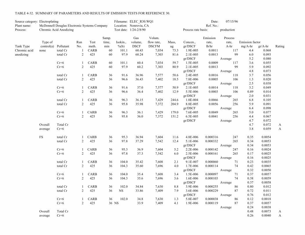
TABLE 4-32. SUMMARY OF PARAMETERS AND RESULTS OF EMISSION TESTS FOR REFERENCE 30.
Source category: Electroplating Filename: ELEC_R30.WQ1 Date: 07/15/96Plant name: McDonnell Douglas Electronic Systems Company Location: Nonrovia, CA Ref. No.:Process: Chromic Acid Anodizing Test date: 1/24-2/8/90 Process rate basis: production
Samp. Gas Volum. Emission ProcessType of Run Test time, Isokin., volume, flow rate, Mass, Concen., rate, rate, Emission factor
Tank Type control(a) Pollutant No. meth. min %(b) DSCF DSCFM ug gr/DSCF lb/hr A-hr mg/A-hr gr/A-hr RatingChromic acid none total Cr 1 CARB 60 101.1 60.43 7,034 73.3 1.9E-005 0.0011 117 4.4 0.068anodizing total Cr 2 425 60 97.9 60.24 7,303 81.6 2.1E-005 0.0013 99 6.0 0.093
gr/DSCF Average 5.2 0.080Cr+6 1 CARB 60 101.1 60.4 7,034 59.7 1.5E-005 0.0009 117 3.6 0.055Cr+6 2 425 60 97.9 60.2 7,303 80.9 2.1E-005 0.0013 99 5.9 0.092
gr/DSCF Average 4.8 0.073total Cr 1 CARB 36 91.6 36.96 7,577 58.6 2.4E-005 0.0016 118 3.7 0.056total Cr 2 425 36 96.6 36.43 7,402 18.5 7.8E-006 0.0005 106 1.3 0.020
gr/DSCF Average 2.5 0.038Cr+6 1 CARB 36 91.6 37.0 7,577 50.9 2.1E-005 0.0014 118 3.2 0.049Cr+6 2 425 36 96.6 36.4 7,402 12.9 5.5E-006 0.0003 106 0.89 0.014
gr/DSCF Average 2.0 0.031total Cr 1 CARB 36 96.3 36.15 7,429 244.6 1.0E-004 0.0066 265 6.8 0.105total Cr 2 425 36 95.8 35.98 7,372 204.9 8.8E-005 0.0056 256 5.9 0.091
gr/DSCF Average 6.4 0.098Cr+6 1 CARB 36 96.3 36.1 7,429 179.0 7.6E-005 0.0049 265 5.0 0.077Cr+6 2 425 36 95.8 36.0 7,372 151.2 6.5E-005 0.0041 256 4.4 0.067
gr/DSCF Average 4.7 0.072Overall Total Cr 4.7 0.072 Aaverage Cr+6 3.8 0.059 A
FS total Cr 1 CARB 36 95.3 36.94 7,604 11.6 4.8E-006 0.000316 247 0.35 0.0054total Cr 2 425 36 97.8 37.29 7,542 12.4 5.1E-006 0.000332 265 0.34 0.0053
gr/DSCF Average 0.34 0.0053Cr+6 1 CARB 36 95.3 36.9 7,604 5.2 2.2E-006 0.000142 247 0.16 0.0024Cr+6 2 425 36 97.8 37.3 7,542 6.0 2.5E-006 0.000161 265 0.17 0.0025
gr/DSCF Average 0.16 0.0025total Cr 1 CARB 36 104.0 35.42 7,608 2.1 9.1E-007 0.000060 71 0.23 0.0035total Cr 2 425 36 104.3 35.60 7,696 4.0 1.7E-006 0.000114 74 0.42 0.0065
gr/DSCF Average 0.32 0.0050Cr+6 1 CARB 36 104.0 35.4 7,608 3.4 1.5E-006 0.000097 71 0.37 0.0057Cr+6 2 425 36 104.3 35.6 7,696 3.6 1.6E-006 0.000103 74 0.38 0.0059
gr/DSCF Average 0.37 0.0058total Cr 1 CARB 36 102.0 34.84 7,630 8.8 3.9E-006 0.000255 86 0.80 0.012total Cr 2 425 36 NS 33.86 7,409 7.9 3.6E-006 0.000229 87 0.72 0.011
gr/DSCF Average 0.76 0.012Cr+6 1 CARB 36 102.0 34.8 7,630 1.3 5.8E-007 0.000038 86 0.12 0.0018Cr+6 2 425 36 NS 33.9 7,409 4.1 1.9E-006 0.000119 87 0.37 0.0057
Average 0.24 0.0038Overall Total Cr 0.48 0.0073 Aaverage Cr+6 0.26 0.0040 A

TABLE 4-32 (continued)
Samp. Gas Volum. Emission ProcessType of Run Test time, Isokin., volume, flow rate, Mass, Concen., rate, rate, Emission factor
Tank Type control(a) Pollutant No. meth. min %(b) DSCF DSCFM ug gr/DSCF lb/hr A-hr mg/A-hr gr/A-hr RatingFS/PB total Cr 1 CARB 36 97.4 35.15 7,577 3.3 1.4E-006 0.000094 85 0.30 0.0047
total Cr 2 425 36 NS 34.62 7,511 2.7 1.2E-006 0.000077 83 0.25 0.0039gr/DSCF Average 0.28 0.0043
Cr+6 1 CARB 36 97.4 35.1 7,577 2.4 1.1E-006 0.000068 85 0.22 0.0034Cr+6 2 425 36 NS 34.6 7,511 1.2 5.3E-007 0.000034 83 0.11 0.0017
gr/DSCF Average 0.17 0.0026total Cr 1 CARB 36 104.8 35.86 7,646 3.5 1.5E-006 0.000099 243 0.11 0.0017total Cr 2 425 36 104.0 34.92 7,572 1.8 8.0E-007 0.000052 297 0.047 0.00073
gr/DSCF Average 0.079 0.0012Cr+6 1 CARB 36 104.8 35.9 7,646 2.4 1.0E-006 0.000068 243 0.076 0.0012Cr+6 2 425 36 104.0 34.9 7,572 2.3 1.0E-006 0.000066 297 0.060 0.00093
gr/DSCF Average 0.068 0.0011total Cr 1 CARB 36 104.7 69.94 7,531 4.0 8.8E-007 0.000057 64 0.24 0.0038total Cr 2 425 36 103.0 68.52 7,436 7.1 1.6E-006 0.000102 62 0.45 0.0069
gr/DSCF Average 0.35 0.0053Cr+6 1 CARB 36 104.7 69.9 7,531 2.3 5.1E-007 0.000033 64 0.14 0.0022Cr+6 2 425 36 103.0 68.5 7,436 5.7 1.3E-006 0.000082 62 0.36 0.0056

TABLE 4-32 (continued)
Samp. Gas Volum. Emission ProcessType of Run Test time, Isokin., volume, flow rate, Mass, Concen., rate, rate, Emission factor
Tank Type control(a) Pollutant No. meth. min %(b) DSCF DSCFM ug gr/DSCF lb/hr ft2 g/hr-m2 gr/hr-ft2 RatingChromic acid none total Cr 1 CARB 60 101.1 60.43 7,034 73.3 1.9E-005 0.0011 21 0.26 0.37anodizing total Cr 2 425 60 97.9 60.24 7,303 81.6 2.1E-005 0.0013 21 0.30 0.43
gr/DSCF Average 0.28 0.40Cr+6 1 CARB 60 101.1 60.4 7,034 59.7 1.5E-005 0.0009 21 0.21 0.30Cr+6 2 425 60 97.9 60.2 7,303 80.9 2.1E-005 0.0013 21 0.30 0.43
gr/DSCF Average 0.26 0.37total Cr 1 CARB 36 91.6 36.96 7,577 58.6 2.4E-005 0.0016 21 0.37 0.52total Cr 2 425 36 96.6 36.43 7,402 18.5 7.8E-006 0.0005 21 0.11 0.16
gr/DSCF Average 0.24 0.34Cr+6 1 CARB 36 91.6 37.0 7,577 50.9 2.1E-005 0.0014 21 0.32 0.46Cr+6 2 425 36 96.6 36.4 7,402 12.9 5.5E-006 0.0003 21 0.080 0.11
gr/DSCF Average 0.20 0.29total Cr 1 CARB 36 96.3 36.15 7,429 244.6 1.0E-004 0.0066 21 1.5 2.2total Cr 2 425 36 95.8 35.98 7,372 204.9 8.8E-005 0.0056 21 1.3 1.8
gr/DSCF Average 1.4 2.0Cr+6 1 CARB 36 96.3 36.1 7,429 179.0 7.6E-005 0.0049 21 1.1 1.6Cr+6 2 425 36 95.8 36.0 7,372 151.2 6.5E-005 0.0041 21 0.94 1.4
gr/DSCF Average 1.0 1.5Overall Total Cr 0.64 0.92 Aaverage Cr+6 0.50 0.71 A
FS total Cr 1 CARB 36 95.3 36.94 7,604 11.6 4.8E-006 0.000316 21 0.073 0.10total Cr 2 425 36 97.8 37.29 7,542 12.4 5.1E-006 0.000332 21 0.076 0.11
gr/DSCF Average 0.075 0.11Cr+6 1 CARB 36 95.3 36.9 7,604 5.2 2.2E-006 0.000142 21 0.033 0.047Cr+6 2 425 36 97.8 37.3 7,542 6.0 2.5E-006 0.000161 21 0.037 0.053
gr/DSCF Average 0.035 0.050total Cr 1 CARB 36 104.0 35.42 7,608 2.1 9.1E-007 0.000060 21 0.014 0.020total Cr 2 425 36 104.3 35.60 7,696 4.0 1.7E-006 0.000114 21 0.026 0.038
gr/DSCF Average 0.020 0.029Cr+6 1 CARB 36 104.0 35.4 7,608 3.4 1.5E-006 0.000097 21 0.022 0.032Cr+6 2 425 36 104.3 35.6 7,696 3.6 1.6E-006 0.000103 21 0.024 0.034
gr/DSCF Average 0.023 0.033total Cr 1 CARB 36 102.0 34.84 7,630 8.8 3.9E-006 0.000255 21 0.059 0.084total Cr 2 425 36 NS 33.86 7,409 7.9 3.6E-006 0.000229 21 0.053 0.075
gr/DSCF Average 0.056 0.080Cr+6 1 CARB 36 102.0 34.8 7,630 1.3 5.8E-007 0.000038 21 0.0087 0.012Cr+6 2 425 36 NS 33.9 7,409 4.1 1.9E-006 0.000119 21 0.027 0.039
Average 0.018 0.026Overall Total Cr 0.050 0.072 Aaverage Cr+6 0.025 0.036 A
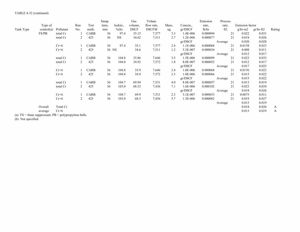
TABLE 4-32 (continued)
Samp. Gas Volum. Emission ProcessType of Run Test time, Isokin., volume, flow rate, Mass, Concen., rate, rate, Emission factor
Tank Type control(a) Pollutant No. meth. min %(b) DSCF DSCFM ug gr/DSCF lb/hr ft2 g/hr-m2 gr/hr-ft2 RatingFS/PB total Cr 1 CARB 36 97.4 35.15 7,577 3.3 1.4E-006 0.000094 21 0.022 0.031
total Cr 2 425 36 NS 34.62 7,511 2.7 1.2E-006 0.000077 21 0.018 0.026gr/DSCF Average 0.020 0.028
Cr+6 1 CARB 36 97.4 35.1 7,577 2.4 1.1E-006 0.000068 21 0.0158 0.023Cr+6 2 425 36 NS 34.6 7,511 1.2 5.3E-007 0.000034 21 0.008 0.011
gr/DSCF Average 0.012 0.017total Cr 1 CARB 36 104.8 35.86 7,646 3.5 1.5E-006 0.000099 21 0.023 0.033total Cr 2 425 36 104.0 34.92 7,572 1.8 8.0E-007 0.000052 21 0.012 0.017
gr/DSCF Average 0.017 0.025Cr+6 1 CARB 36 104.8 35.9 7,646 2.4 1.0E-006 0.000068 21 0.0156 0.022Cr+6 2 425 36 104.0 34.9 7,572 2.3 1.0E-006 0.000066 21 0.015 0.022
gr/DSCF Average 0.015 0.022total Cr 1 CARB 36 104.7 69.94 7,531 4.0 8.8E-007 0.000057 21 0.013 0.019total Cr 2 425 36 103.0 68.52 7,436 7.1 1.6E-006 0.000102 21 0.023 0.034
gr/DSCF Average 0.018 0.026Cr+6 1 CARB 36 104.7 69.9 7,531 2.3 5.1E-007 0.000033 21 0.0075 0.011Cr+6 2 425 36 103.0 68.5 7,436 5.7 1.3E-006 0.000082 21 0.019 0.027
Average 0.013 0.019Overall Total Cr 0.018 0.026 Aaverage Cr+6 0.013 0.019 A
(a) FS = fume suppressant; PB = polypropylene balls.(b) Not specified.

4-82
TABLE 4-33. SUMMARY OF PARAMETERS AND RESULTS OF EMISSION TESTS FORREFERENCE 31
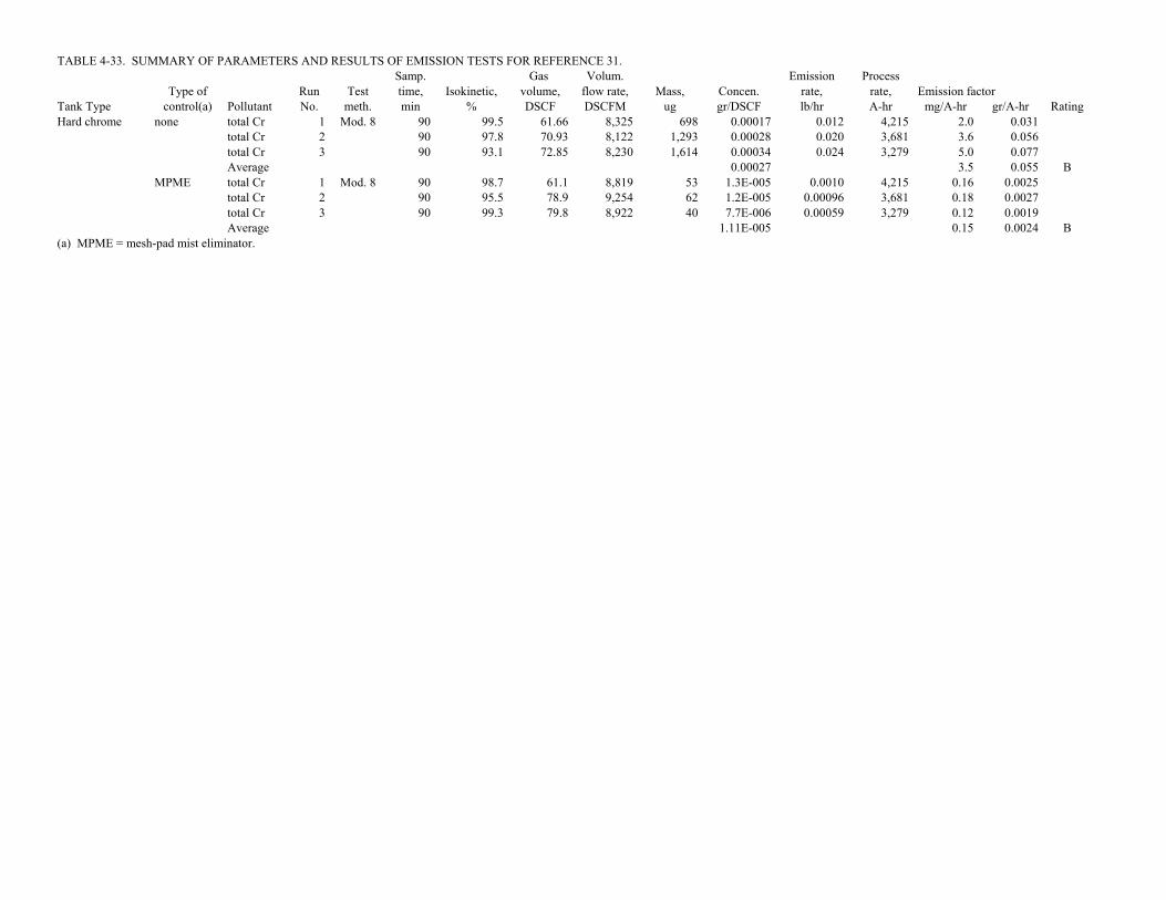
TABLE 4-33. SUMMARY OF PARAMETERS AND RESULTS OF EMISSION TESTS FOR REFERENCE 31.Samp. Gas Volum. Emission Process
Type of Run Test time, Isokinetic, volume, flow rate, Mass, Concen. rate, rate, Emission factorTank Type control(a) Pollutant No. meth. min % DSCF DSCFM ug gr/DSCF lb/hr A-hr mg/A-hr gr/A-hr RatingHard chrome none total Cr 1 Mod. 8 90 99.5 61.66 8,325 698 0.00017 0.012 4,215 2.0 0.031
total Cr 2 90 97.8 70.93 8,122 1,293 0.00028 0.020 3,681 3.6 0.056total Cr 3 90 93.1 72.85 8,230 1,614 0.00034 0.024 3,279 5.0 0.077Average 0.00027 3.5 0.055 B
MPME total Cr 1 Mod. 8 90 98.7 61.1 8,819 53 1.3E-005 0.0010 4,215 0.16 0.0025total Cr 2 90 95.5 78.9 9,254 62 1.2E-005 0.00096 3,681 0.18 0.0027total Cr 3 90 99.3 79.8 8,922 40 7.7E-006 0.00059 3,279 0.12 0.0019Average 1.11E-005 0.15 0.0024 B
(a) MPME = mesh-pad mist eliminator.

4-83
TABLE 4-34. SUMMARY OF PARAMETERS AND RESULTS OF EMISSION TESTS FORREFERENCE 33

TABLE 4-34. SUMMARY OF PARAMETERS AND RESULTS OF EMISSION TEST FOR REFERENCE 33.Samp. Gas Volum. Emission Process
Type of Run Test time, Isokin. volume, flow rate, Mass, Concen. rate, rate, Emission factorSource control(a) Pollutant No. Meth. min % DSCF DSCFM ug gr/DSCF lb/hr A-hr mg/A-hr gr/A-hr RatingHard chrome none filterable PM 1 5 60 98.8 58.36 20,085 87,200 0.0231 4.0 5,500 327 5.1
filterable PM 2 60 99.5 58.96 20,155 121,400 0.0318 5.5 5,500 453 7.0filterable PM 3 60 98.2 60.72 21,029 102,400 0.0260 4.7 5,500 387 6.0Average 0.0270 389 6.0 NRtotal Cr 1 5 60 98.8 58.36 20,085 18,900 0.00500 0.86 5,500 71 1.1total Cr 2 60 99.5 58.96 20,155 23,500 0.00615 1.1 5,500 88 1.4total Cr 3 60 98.2 60.72 21,029 21,100 0.00536 0.97 5,500 80 1.2Average 0.00550 79 1.2 D
MPME filterable PM 1 5 60 103.0 62.3 19,605 16,500 0.00409 0.69 5,500 57 0.87filterable PM 2 60 105.4 63.8 19,648 20,500 0.00496 0.84 5,500 69 1.1filterable PM 3 60 105.9 64.8 19,857 21,100 0.00503 0.86 5,500 71 1.1Average 0.00469 65 1.0 NRtotal Cr 1 5 60 103.0 62.25 19,605 5,300 0.00131 0.22 5,500 18 0.28total Cr 2 60 105.4 63.80 19,648 4,800 0.00116 0.20 5,500 16 0.25total Cr 3 60 105.9 64.78 19,857 6,300 0.00150 0.26 5,500 21 0.33Average 0.00133 18 0.28 D
(a) MPME = mesh pad mist eliminator.

4-84
TABLE 4-35. SUMMARY OF PARAMETERS AND RESULTS OF EMISSION TESTS FORREFERENCE 58

TABLE 4-35. SUMMARY OF PARAMETERS AND RESULTS OF EMISSION TESTS FOR REFERENCE 58.Samp. Gas Volum. Emission Process
Type of Run Test time, Isokin. volume, flow rate, Mass, Concen., rate, rate, Emission factorTank type control(a) Pollutant No. Meth. min % DSCF DSCFM ug gr/DSCF lb/hr A-hr mg/A-hr gr/A-hr RatingDecorative chrome FS total Cr 1 Imping. 320 98.7 234.39 11,947 80.5 5.30E-006 0.00054 25,000 0.053 0.00081
total Cr 4 320 98.6 234.82 11,980 45.4 2.98E-006 0.00031 22,100 0.034 0.00052total Cr 7 320 98.4 234.253 11,983 88.9 5.86E-006 0.00060 26,300 0.055 0.00085Average 4.71E-006 0.047 0.00073 NRCr+6 4 320 98.7 234.388 11,947 15.6 1.03E-006 0.00011 25,000 0.010 0.00016Cr+6 5 320 98.6 234.821 11,980 13.4 8.81E-007 9.0E-005 22,100 0.0099 0.00015Cr+6 6 320 98.4 234.253 11,983 20.8 1.37E-006 0.00014 26,300 0.013 0.00020Average 1.09E-006 0.011 0.00017 NR
FS filt. PM 2 5 320 97.6 230.186 11,416 8,300 0.00056 0.0544 25,000 5.3 0.081filt. PM 5 320 100.6 229.972 11,065 1,300 8.7E-005 0.0083 22,100 0.91 0.014filt. PM 8 320 99.2 240.408 11,719 6,700 0.00043 0.0432 26,300 4.0 0.061Average 0.00036 3.4 0.052 NRtotal Cr 2 5 320 97.6 230.186 11,416 3,500 0.00023 0.02296 25,000 2.2 0.034total Cr 5 320 100.6 229.972 11,065 10,800 0.00072 0.06874 22,100 7.5 0.12total Cr 8 320 99.2 240.408 11,719 16,200 0.00104 0.10446 26,300 9.6 0.15Average 0.00067 6.5 0.10 NRCr+6 2 5 320 97.6 230.186 11,416 800 0.00005 0.00525 25,000 0.51 0.0078Cr+6 5 320 100.6 229.972 11,065 2,800 0.00019 0.0178 22,100 2.0 0.030Cr+6 8 320 99.2 240.408 11,719 4,200 0.00027 0.02708 26,300 2.5 0.038Average 0.00017 1.6 0.025 NR
FS/PBS filt. PM 3 5 288 94.2 275.95 12,477 23,300filt. PM 6 288 94.6 276.54 12,443 4,100 0.00023 0.02440 20,500 2.6 0.040filt. PM 9 288 94.5 275.27 12,404 0.00000 23,400Average 0.00011 2.6 0.040 NRtotal Cr 3 5 320 94.2 275.95 12,477 18,800 0.00105 0.11244 23,300 12 0.18total Cr 6 320 94.6 276.54 12,443 14,300 0.00080 0.08511 20,500 10 0.15total Cr 9 320 94.5 275.27 12,404 14,800 0.00083 0.08822 23,400 9.1 0.14Average 0.00089 10 0.16 NRCr+6 3 5 320 98.7 275.95 12,477 2,100 0.00012 0.01256 23,300 1.3 0.020Cr+6 6 320 98.6 276.54 12,443 2,700 0.00015 0.01607 20,500 1.9 0.029Cr+6 9 320 98.4 275.27 12,404 3,200 0.00018 0.01907 23,400 2.0 0.030Average 0.00015 1.7 0.027 NR
(a) FS = fume suppressant; PBS = packed bed scrubber.

4-85
TABLE 4-36. SUMMARY OF PARAMETERS AND RESULTS OF EMISSION TESTS FORREFERENCE 59

TABLE 4-36. SUMMARY OF PARAMETERS AND RESULTS OF EMISSION TEST FOR REFERENCE 59.Samp. Gas Volum. Emission Process
Type of Run Test time, Isokin. volume, flow rate, Mass, Concen., rate, rate, Emission factorTank type control(a) Pollutant No. Meth. min % DSCF DSCFM ug gr/DSCF lb/hr A-hr mg/A-hr gr/A-hr RatingHard chrome none filt. PM 2 5 288 97.1 283.08 9,315 60,500 0.00330 0.26 25,000 23 0.35
filt. PM 5 288 100.1 274.72 8,773 38,600 0.0022 0.16 22,100 16 0.25filt. PM 8 288 98.9 275.08 8,888 51,300 0.00288 0.22 26,300 18 0.28Average 0.00278 19 0.29 NRtotal Cr 2 5 288 97.1 283.08 9,315 14,977 0.00082 0.06519 25,000 5.7 0.088total Cr 5 288 100.1 274.72 8,773 7,993 0.00045 0.03376 22,100 3.3 0.051total Cr 8 288 98.9 275.08 8,888 13,345 0.00075 0.05703 26,300 4.7 0.073Average 0.00067 4.6 0.071 NRCr+6 2 5 288 97.1 283.08 9,315 7,200 0.000 0.03134 25,000 2.7 0.042Cr+6 5 288 100.1 274.72 8,773 3,680 0.00021 0.01554 22,100 1.5 0.024Cr+6 8 288 98.9 275.08 8,888 6,520 0.00037 0.02787 26,300 2.3 0.036Average 0.00032 2.2 0.034 NR
PBS filt. PM 3 5 288 95.9 208.92 10,410 15,500 0.00114 0.102 23,300 9.5 0.15filt. PM 6 288 96.5 211.21 10,464 20,400 0.00149 0.134 20,500 14 0.22filt. PM 9 288 95.8 203.93 10,171 16,100 0.00122 0.106 23,400 9.9 0.15Average 0.00128 11 0.17 NRtotal Cr 3 5 288 95.9 208.92 10,410 728 5.38E-005 0.00480 23,300 0.45 0.0069total Cr 6 288 96.5 211.21 10,464 305 2.23E-005 0.00200 20,500 0.21 0.0033total Cr 9 288 95.8 203.93 10,171 647 4.90E-005 0.00427 23,400 0.40 0.0061Average 4.17E-005 0.35 0.0054 NRCr+6 3 5 288 95.9 208.92 10,410 155 1.14E-005 0.00102 23,300 0.095 0.0015Cr+6 6 288 96.5 211.21 10,464 121 8.84E-006 0.00079 20,500 0.084 0.0013Cr+6 9 288 95.8 203.93 10,171 174 1.32E-005 0.00115 23,400 0.11 0.0016Average 1.12E-005 0.095 0.0015 NR
(a) PBS = packed bed scrubber.

4-86
TABLE 4-37. SUMMARY OF PARAMETERS AND RESULTS OF EMISSION TESTS FORREFERENCE 62

TABLE 4-37. SUMMARY OF PARAMETERS AND RESULTS OF EMISSION TEST FOR REFERENCE 62.Samp. Gas Volum. Emission Process
Type of Run Test time, Isokin. volume, flow rate, Mass, Concen., rate, rate, Emission factorTank type control(a) Pollutant No. Meth. min % DSCF DSCFM ug gr/DSCF lb/hr ft2 g/hr-m2 gr/hr-ft2 RatingChromic acid none total Cr 1 CARB 40 100.6 37.37 3,318 688.60 0.00028 0.00809 28 1.4 2.0anodizing total Cr 2 425 40 96.0 37.31 3,271 450.00 0.00019 0.00522 28 0.91 1.3
Average 0.00024 1.2 1.7 BCr+6 1 CARB 40 100.6 37.37 3,318 443.70 0.00018 0.00521 28 0.91 1.3Cr+6 2 425 40 96.0 37.31 3,271 270.00 0.00011 0.00313 28 0.55 0.78Average 0.00015 0.73 1.0 B
AM total Cr 3 CARB 40 106.0 40.58 3,432 34.90 1.33E-005 0.00039 28 0.068 0.098total Cr 4 425 40 104.6 39.24 3,344 23.30 9.16E-006 0.00026 28 0.046 0.066Average 1.12E-005 0.057 0.082 BCr+6 1 CARB 40 106.0 40.58 3,432 28Cr+6 2 425 40 104.6 39.24 3,344 28
Average(a) AM = antimisting agent.

4-87
TABLE 4-38. SUMMARY OF PARAMETERS AND RESULTS OF EMISSION TESTS FORREFERENCE 63
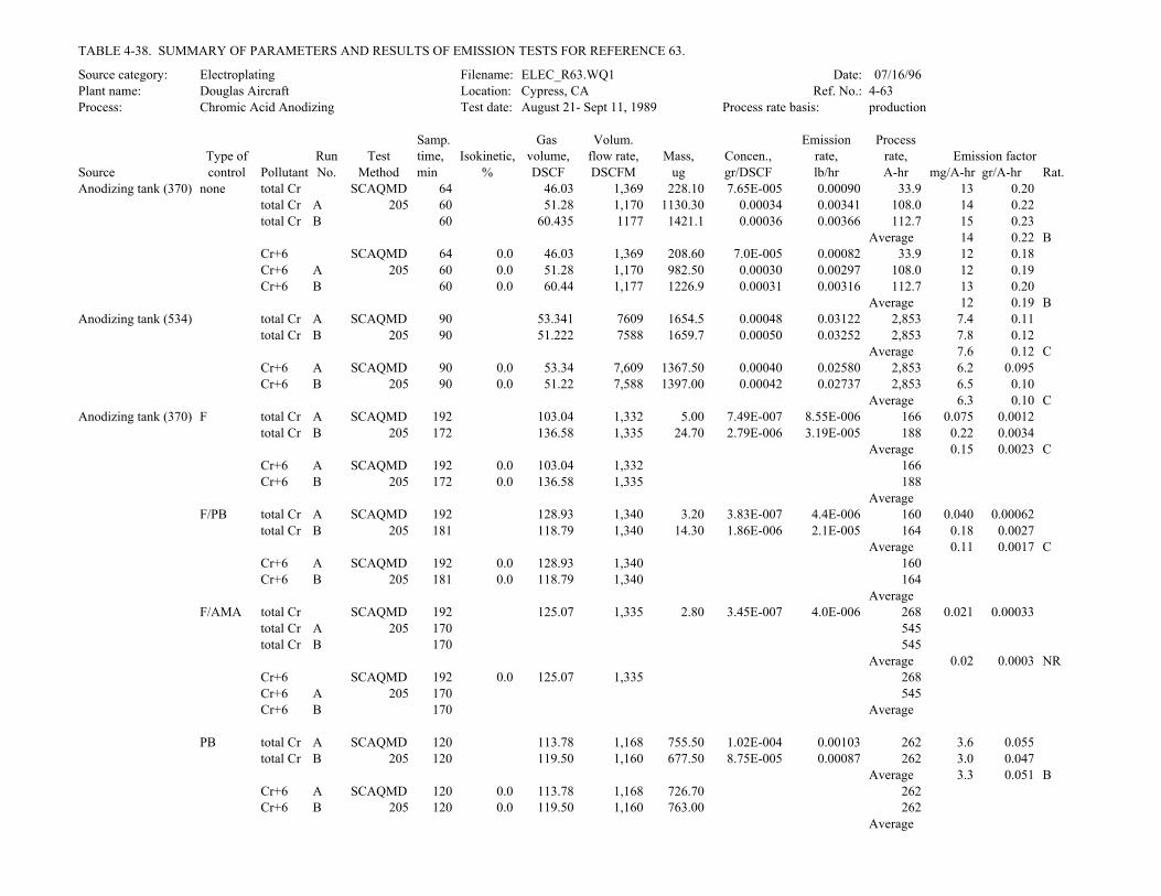
TABLE 4-38. SUMMARY OF PARAMETERS AND RESULTS OF EMISSION TESTS FOR REFERENCE 63.
Source category: Electroplating Filename: ELEC_R63.WQ1 Date: 07/16/96Plant name: Douglas Aircraft Location: Cypress, CA Ref. No.: 4-63Process: Chromic Acid Anodizing Test date: August 21- Sept 11, 1989 Process rate basis: production
Samp. Gas Volum. Emission ProcessType of Run Test time, Isokinetic, volume, flow rate, Mass, Concen., rate, rate, Emission factor
Source control Pollutant No. Method min % DSCF DSCFM ug gr/DSCF lb/hr A-hr mg/A-hr gr/A-hr Rat.Anodizing tank (370) none total Cr SCAQMD 64 46.03 1,369 228.10 7.65E-005 0.00090 33.9 13 0.20
total Cr A 205 60 51.28 1,170 1130.30 0.00034 0.00341 108.0 14 0.22total Cr B 60 60.435 1177 1421.1 0.00036 0.00366 112.7 15 0.23
Average 14 0.22 BCr+6 SCAQMD 64 0.0 46.03 1,369 208.60 7.0E-005 0.00082 33.9 12 0.18Cr+6 A 205 60 0.0 51.28 1,170 982.50 0.00030 0.00297 108.0 12 0.19Cr+6 B 60 0.0 60.44 1,177 1226.9 0.00031 0.00316 112.7 13 0.20
Average 12 0.19 BAnodizing tank (534) total Cr A SCAQMD 90 53.341 7609 1654.5 0.00048 0.03122 2,853 7.4 0.11 total Cr B 205 90 51.222 7588 1659.7 0.00050 0.03252 2,853 7.8 0.12
Average 7.6 0.12 CCr+6 A SCAQMD 90 0.0 53.34 7,609 1367.50 0.00040 0.02580 2,853 6.2 0.095Cr+6 B 205 90 0.0 51.22 7,588 1397.00 0.00042 0.02737 2,853 6.5 0.10
Average 6.3 0.10 CAnodizing tank (370) F total Cr A SCAQMD 192 103.04 1,332 5.00 7.49E-007 8.55E-006 166 0.075 0.0012
total Cr B 205 172 136.58 1,335 24.70 2.79E-006 3.19E-005 188 0.22 0.0034Average 0.15 0.0023 C
Cr+6 A SCAQMD 192 0.0 103.04 1,332 166Cr+6 B 205 172 0.0 136.58 1,335 188
AverageF/PB total Cr A SCAQMD 192 128.93 1,340 3.20 3.83E-007 4.4E-006 160 0.040 0.00062
total Cr B 205 181 118.79 1,340 14.30 1.86E-006 2.1E-005 164 0.18 0.0027Average 0.11 0.0017 C
Cr+6 A SCAQMD 192 0.0 128.93 1,340 160Cr+6 B 205 181 0.0 118.79 1,340 164
AverageF/AMA total Cr SCAQMD 192 125.07 1,335 2.80 3.45E-007 4.0E-006 268 0.021 0.00033
total Cr A 205 170 545total Cr B 170 545
Average 0.02 0.0003 NRCr+6 SCAQMD 192 0.0 125.07 1,335 268Cr+6 A 205 170 545Cr+6 B 170 Average
PB total Cr A SCAQMD 120 113.78 1,168 755.50 1.02E-004 0.00103 262 3.6 0.055total Cr B 205 120 119.50 1,160 677.50 8.75E-005 0.00087 262 3.0 0.047
Average 3.3 0.051 BCr+6 A SCAQMD 120 0.0 113.78 1,168 726.70 262Cr+6 B 205 120 0.0 119.50 1,160 763.00 262
Average

TABLE 4-38 (continued)Samp. Gas Volum. Emission Process
Type of Run Test time, Isokinetic, volume, flow rate, Mass, Concen., rate, rate, Emission factorSource control Pollutant No. Method min % DSCF DSCFM ug gr/DSCF lb/hr ft2 g/hr-m2 gr/hr-ft2 Rat.Anodizing tank (370) none total Cr SCAQMD 64 46.03 1,369 228.10 7.65E-005 0.00090 3.8 1.1 1.6
total Cr A 205 60 51.28 1,170 1130.30 0.00034 0.00341 3.8 4.3 6.2total Cr B 60 60.435 1177 1421.1 0.00036 0.00366 3.8 4.7 6.7
Average 3.4 4.8 BCr+6 SCAQMD 64 0.0 46.03 1,369 208.60 7.0E-005 0.00082 3.8 1.0 1.5Cr+6 A 205 60 0.0 51.28 1,170 982.50 0.00030 0.00297 3.8 3.8 5.4Cr+6 B 60 0.0 60.44 1,177 1226.9 0.00031 0.00316 3.8 4.0 5.8
Average 2.9 4.2 BAnodizing tank (534) total Cr A SCAQMD 90 53.341 7609 1654.5 0.00048 0.03122 total Cr B 205 90 51.222 7588 1659.7 0.00050 0.03252
CCr+6 A SCAQMD 90 0.0 53.34 7,609 1367.50 0.00040 0.02580Cr+6 B 205 90 0.0 51.22 7,588 1397.00 0.00042 0.02737
CAnodizing tank (370) F total Cr A SCAQMD 192 103.04 1,332 5.00 7.49E-007 8.55E-006 3.8 0.011 0.016
total Cr B 205 172 136.58 1,335 24.70 2.79E-006 3.19E-005 3.8 0.041 0.058Average 0.026 0.037 C
Cr+6 A SCAQMD 192 0.0 103.04 1,332 3.8Cr+6 B 205 172 0.0 136.58 1,335 3.8
AverageF/PB total Cr A SCAQMD 192 128.93 1,340 3.20 3.83E-007 4.4E-006 3.8 0.0056 0.0080
total Cr B 205 181 118.79 1,340 14.30 1.86E-006 2.1E-005 3.8 0.027 0.039Average 0.016 0.023 C
Cr+6 A SCAQMD 192 0.0 128.93 1,340 3.8Cr+6 B 205 181 0.0 118.79 1,340 3.8
AverageF/AMA total Cr SCAQMD 192 125.07 1,335 2.80 3.45E-007 4.0E-006 3.8 0.0050 0.0072
total Cr A 205 170 3.8total Cr B 170 3.8
Average 0.0050 0.0072 NRCr+6 SCAQMD 192 0.0 125.07 1,335 3.8Cr+6 A 205 170 3.8Cr+6 B 170 Average
PB total Cr A SCAQMD 120 113.78 1,168 755.50 1.02E-004 0.00103 3.8 1.3 1.9total Cr B 205 120 119.50 1,160 677.50 8.75E-005 0.00087 3.8 1.1 1.6
Average 1.2 1.7 BCr+6 A SCAQMD 120 0.0 113.78 1,168 726.70 3.8Cr+6 B 205 120 0.0 119.50 1,160 763.00 3.8
AverageBasis for rating: All downrated due to lack of adequate documentation; further downrated if only two runs conducted.Problems noted:Other notes: AMA = antimisting agent; F = foam; PB = polypropylene balls
Factors not calculated if mass below quantitation limit.

4-89
TABLE 4-39. SUMMARY OF PARAMETERS AND RESULTS OF EMISSION TESTS FORREFERENCE 66

TABLE 4-39. SUMMARY OF PARAMETERS AND RESULTS OF EMISSION TEST FOR REFERENCE 66.Samp. Gas Volum. Emission Process
Type of Run Test time, volume, flow rate, Mass, Concen., rate, rate, Emission factor(b)Tank type control(a) Pollutant No. Method min DSCF DSCFM ug gr/DSCF lb/hr ft2 g/hr-m2 gr/hr-ft2 RatingChromic acid PBS total Cr 1 SCAQMD 468 411.66 4,382 42.14 1.58E-006 5.93E-005 anodizing total Cr 1 205.1 20 13.921 39,306
total Cr 2 480 408.23 4,206 17.05 6.45E-007 2.32E-005total Cr 2 33 26.485 41855
Cr+6 1 SCAQMD 468 411.66 4,382 38.90 1.46E-006 5.48E-005Cr+6 2 205.1 20 13.92 39,306 1.00 1.11E-006 0.00037Cr+6 1 480 408.23 4,206Cr+6 2 33 26.49 41,855 0.04 2.33E-008 8.36E-006
PBS total Cr 1 SCAQMD 480 359.40 6,261 421.60 1.81E-005 0.00097total Cr 1 205.1 23 13.115 62,575total Cr 2 484 314.63 5,897 127.80 6.27E-006 0.00032total Cr 2 32 19.194 56954 7.28 5.85E-006 0.0029
Cr+6 1 SCAQMD 480 359.40 6,261 373.95 1.61E-005 0.00086Cr+6 2 205.1 23 13.12 62,575 0.35 4.12E-007 0.00022Cr+6 1 484 314.63 5,897 2.01 9.86E-008 4.98E-006Cr+6 2 32 19.19 56,954 0.13 1.05E-007 5.10E-005
PBS total Cr 1 SCAQMD 474 0.0010(Total) total Cr 1 205.1 21.5
total Cr 2 482 0.00034total Cr 2 32.5 0.0029
AverageCr+6 1 SCAQMD 474 0.00092Cr+6 2 205.1 21.5 0.00059Cr+6 1 482 5.0E-006Cr+6 2 32.5 5.9E-005
Average(a) PBS = packed bed scrubber; emission factors based on sum of emission rates from both scrubbers.(b) Tank dimensions not specified; emission factor could not be calculated.

4-90
TABLE 4-40. SUMMARY OF PARAMETERS AND RESULTS OF EMISSION TESTS FOR REFERENCE 67

TABLE 4-40. SUMMARY OF PARAMETERS AND RESULTS OF EMISSION TESTS FOR REFERENCE 67.Samp. Gas Volum. Emission Process
Type of Run Test time, Isokin. volume, flow rate, Mass, Concen., rate, rate, Emission factorTank type control(b) Pollutant No. Meth. min % DSCF DSCFM ug (c) gr/DSCF lb/hr A-hr mg/A-hr gr/A-hr RatingChromic acid None total Cr 1 CARB 75 90.8 54.33 38,042 5.65 1.60E-006 0.00052 ND NA NAanodizing total Cr 2 425 85 93.3 50.24 34,254 2.73 8.39E-007 0.00025 ND NA NA
total Cr 3 80 91.9 50.00 34,603 0.09 2.78E-008 8.2E-006 ND NA NAfilt. PM 8 320 8.24E-007 Average NRCr+6 1 CARB 75 90.8 54.3 38,042 BDL NA NA ND NA NACr+6 2 425 85 93.3 50.2 34,254 BDL NA NA ND NA NACr+6 3 80 91.9 50.0 34,603 BDL NA NA ND NA NAtotal Cr 8 320 Average NR
WS total Cr 1 CARB 75 100.2 47.88 40,173 3.70 1.19E-006 0.00041 ND NA NAtotal Cr 2 425 85 103.9 48.79 39,486 0.36 1.14E-007 3.9E-005 ND NA NAtotal Cr 3 80 101.3 48.10 33,990 0.80 2.57E-007 7.5E-005 ND NA NACr+6 8 320 5.21E-007 Average NRCr+6 1 CARB 75 100.2 47.9 40,173 BDL NA NA ND NA NACr+6 2 425 85 103.9 48.8 39,486 BDL NA NA ND NA NACr+6 3 80 101.3 48.1 33,990 BDL NA NA ND NA NAfilt. PM 9 288 Average NR
Copper plating None copper 1 0012 73 94.3 64.07 29,628 30.0 7.23E-006 0.0018 43.4 23 0.36copper 2 90 93.6 67.82 31,593 BDL NA NA 8.2 NA NAcopper 3 80 91.3 48.72 33,923 BDL NA NA 13.4 NA NAtotal Cr 9 ERR 7.23E-006 Average 23 0.36 NR
None lead 1 0012 73 94.3 64.07 29,628 22.0 5.30E-006 0.0013 0 NA NAlead 2 90 93.6 67.82 31,593 16.0 3.64E-006 0.0010 0 NA NAlead 3 80 91.3 48.72 33,923 13.0 4.12E-006 0.0012 0 NA NACr+6 9 ERR 4.35E-006 Average NR
WS copper 1 0012 73 96.7 45.44 39,508 570.00 0.00019 0.066 43.4 833 13copper 2 90 98.7 46.70 39,783 120.00 3.97E-005 0.014 8.2 1,117 17copper 3 80 102.5 48.33 39,645 33.00 1.05E-005 0.0036 13.4 161 2.5
8.13E-005 Average 704 11 CWS lead 1 0012 73 96.7 45.44 39,508 66.00 2.24E-005 0.0076 0 NA NA
lead 2 90 98.7 46.70 39,783 19.00 6.28E-006 0.0021 0 NA NAlead 3 80 102.5 48.33 39,645 17.00 5.43E-006 0.0018 0 NA NA
1.14E-005 Average NRNickel plating None nickel 1 0012 73 94.3 64.07 29,628 280.00 6.74E-005 0.017 85.1 111 1.7
nickel 2 90 93.6 67.82 31,593 190.00 4.32E-005 0.012 161.8 49 0.76nickel 3 80 91.3 48.72 33,923 31.00 9.82E-006 0.0029 158.7 11 0.17
4.02E-005 Average 57 0.88 BWS nickel 1 0012 73 96.7 45.44 39,508 6.00 2.04E-006 0.00069 85.1 4.5 0.069
nickel 2 90 98.7 46.70 39,783 27.00 8.92E-006 0.0030 161.8 13 0.20nickel 3 80 102.5 48.33 39,645 19.20 6.13E-006 0.0021 158.7 7.9 0.12
5.70E-006 Average 8.4 0.13 B

TABLE 4-40. (Continued)Samp. Gas Volum. Emission Process
Type of Run Test time, Isokin. volume, flow rate, Mass, Concen., rate, rate, Emission factorTank type control(b) Pollutant No. Meth. min % DSCF DSCFM ug gr/DSCF lb/hr A-hr mg/A-hr gr/A-hr RatingNickel plating None nickel 1 CARB 65 90.0 54.28 26,298 117.50 3.34E-005 0.0075 117 32 0.49
nickel 2 424 120 92.1 45.64 31,515 75.00 2.54E-005 0.0068 182 34 0.53nickel 3 90 91.6 48.87 33,937 27.50 8.68E-006 0.0025 200 8.6 0.13
2.25E-005 25 0.38 CWS nickel 1 CARB 65 98.4 47.27 40,387 32.50 1.06E-005 0.0037 117 15 0.24
nickel 2 424 120 100.2 47.64 39,983 25.00 8.10E-006 0.0028 182 14 0.21nickel 3 90 99.0 46.49 39,503 12.50 4.15E-006 0.0014 200 4.8 0.074
7.62E-006 11 0.17 BCadmium plating None cadmium 1 0012 89 96.5 44.22 8,577 98.00 3.42E-005 0.0025 338 5.0 0.077
cadmium 2 73 94.7 40.92 8,090 6.30 2.38E-006 0.00016 548 0.17 0.0026cadmium 3 87 97.4 42.11 8,093 7.60 2.79E-006 0.00019 653 0.19 0.0030
1.31E-005 Average 1.8 0.028 CNone zinc 1 0012 89 96.5 44.22 8,577 9,900 0.0035 0.25 0 NA NA
zinc 2 73 94.7 40.92 8,090 12,000 0.0045 0.31 0 NA NAzinc 3 87 97.4 42.11 8,093 12,000 0.0044 0.31 0 NA NA
0.0041 Average NRWS cadmium 1 0012 89 95.9 47.82 8,987 8.00 2.58E-006 0.00020 338 0.40 0.0061
cadmium 2 73 97.6 48.25 8,914 8.50 2.72E-006 0.00021 548 0.21 0.0032cadmium 3 87 97.8 48.06 8,861 5.80 1.86E-006 0.00014 653 0.14 0.0022
2.4E-006 Average 0.25 0.0038 BWS zinc 1 0012 89 95.9 47.82 8,987 11,000 0.0035 0.27 0 NA NA
zinc 2 73 97.6 48.25 8,914 12,000 0.0038 0.29 0 NA NAzinc 3 87 97.8 48.06 8,861 12,000 0.0039 0.29 0 NA NA
0.0037 Average NRCadmium plating None cadmium 1 CARB 82 94.2 40.19 7,990 5.50 2.11E-006 0.00014 25 3.6 0.055
cadmium 2 433 70 95.0 39.37 7,759 13.75 5.39E-006 0.00036 338 0.56 0.0087cadmium 3 70 94.4 41.18 8,172 9.75 3.65E-006 0.00026 23 6.0 0.093
3.7E-006 Average 3.4 0.052 CWS cadmium 1 CARB 82 98.0 49.59 9,128 9.00 2.80E-006 0.00022 25 5.4 0.084
cadmium 2 433 70 95.5 48.98 9,247 10.50 3.31E-006 0.00026 338 0.41 0.0063cadmium 3 70 91.7 45.31 8,907 46.00 1.57E-005 0.0012 23 28 0.43
7.3E-006 Average 11 0.17 C(a) NA = not applicable, ND = no data.(b) WS = wet scrubber.(c) BDL = below detection limit.

4-93
TABLE 4-41. SUMMARY OF PARAMETERS AND RESULTS OF EMISSION TESTS FOR REFERENCE 71
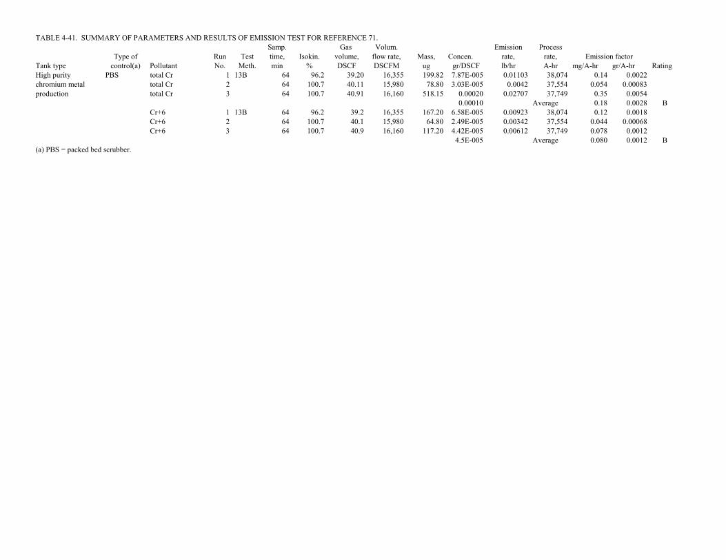
TABLE 4-41. SUMMARY OF PARAMETERS AND RESULTS OF EMISSION TEST FOR REFERENCE 71.Samp. Gas Volum. Emission Process
Type of Run Test time, Isokin. volume, flow rate, Mass, Concen. rate, rate, Emission factorTank type control(a) Pollutant No. Meth. min % DSCF DSCFM ug gr/DSCF lb/hr A-hr mg/A-hr gr/A-hr RatingHigh purity PBS total Cr 1 13B 64 96.2 39.20 16,355 199.82 7.87E-005 0.01103 38,074 0.14 0.0022chromium metal total Cr 2 64 100.7 40.11 15,980 78.80 3.03E-005 0.0042 37,554 0.054 0.00083production total Cr 3 64 100.7 40.91 16,160 518.15 0.00020 0.02707 37,749 0.35 0.0054
0.00010 Average 0.18 0.0028 BCr+6 1 13B 64 96.2 39.2 16,355 167.20 6.58E-005 0.00923 38,074 0.12 0.0018Cr+6 2 64 100.7 40.1 15,980 64.80 2.49E-005 0.00342 37,554 0.044 0.00068Cr+6 3 64 100.7 40.9 16,160 117.20 4.42E-005 0.00612 37,749 0.078 0.0012
4.5E-005 Average 0.080 0.0012 B(a) PBS = packed bed scrubber.

4-94
TABLE 4-42. SUMMARY OF PARAMETERS AND RESULTS OF EMISSION TESTS FOR REFERENCE 74

TABLE 4-42. SUMMARY OF PARAMETERS AND RESULTS OF EMISSION TEST FOR REFERENCE 74.Samp. Gas Volum. Emission Process
Type of Run Test time, Isokin. volume, flow rate, Mass, Concen. rate, rate, Emission factorTank type control Pollutant No. Meth. min % DSCF DSCFM ug gr/DSCF lb/hr A-hr mg/A-hr gr/A-hr RatingHard chromium None Cr+6 1 CARB 60 99.0 23.43 12,600 105.90 6.98E-005 0.0075 2,980 1.1 0.018
Cr+6 2 425 60 98.0 23.12 12,600 104.70 6.99E-005 0.0075 2,980 1.1 0.018Cr+6 3 60 101.0 23.30 12,600 105.60 6.99E-005 0.0076 2,980 1.1 0.018
6.99E-005 Average 1.1 0.018 C

4-95
TABLE 4-43. SUMMARY OF PARAMETERS AND RESULTS OF EMISSION TESTS FOR REFERENCE 75
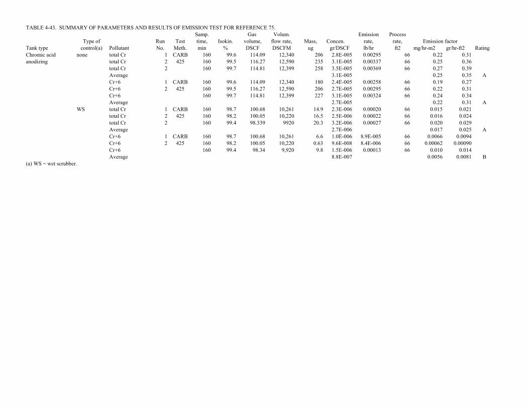
TABLE 4-43. SUMMARY OF PARAMETERS AND RESULTS OF EMISSION TEST FOR REFERENCE 75.Samp. Gas Volum. Emission Process
Type of Run Test time, Isokin. volume, flow rate, Mass, Concen. rate, rate, Emission factorTank type control(a) Pollutant No. Meth. min % DSCF DSCFM ug gr/DSCF lb/hr ft2 mg/hr-m2 gr/hr-ft2 RatingChromic acid none total Cr 1 CARB 160 99.6 114.09 12,340 206 2.8E-005 0.00295 66 0.22 0.31anodizing total Cr 2 425 160 99.5 116.27 12,590 235 3.1E-005 0.00337 66 0.25 0.36
total Cr 2 160 99.7 114.81 12,399 258 3.5E-005 0.00369 66 0.27 0.39Average 3.1E-005 0.25 0.35 ACr+6 1 CARB 160 99.6 114.09 12,340 180 2.4E-005 0.00258 66 0.19 0.27Cr+6 2 425 160 99.5 116.27 12,590 206 2.7E-005 0.00295 66 0.22 0.31Cr+6 160 99.7 114.81 12,399 227 3.1E-005 0.00324 66 0.24 0.34Average 2.7E-005 0.22 0.31 A
WS total Cr 1 CARB 160 98.7 100.68 10,261 14.9 2.3E-006 0.00020 66 0.015 0.021total Cr 2 425 160 98.2 100.05 10,220 16.5 2.5E-006 0.00022 66 0.016 0.024total Cr 2 160 99.4 98.339 9920 20.3 3.2E-006 0.00027 66 0.020 0.029Average 2.7E-006 0.017 0.025 ACr+6 1 CARB 160 98.7 100.68 10,261 6.6 1.0E-006 8.9E-005 66 0.0066 0.0094Cr+6 2 425 160 98.2 100.05 10,220 0.63 9.6E-008 8.4E-006 66 0.00062 0.00090Cr+6 160 99.4 98.34 9,920 9.8 1.5E-006 0.00013 66 0.010 0.014Average 8.8E-007 0.0056 0.0081 B
(a) WS = wet scrubber.
4-96
TABLE 4-44. SUMMARY OF PARAMETERS AND RESULTS OF EMISSION TESTS FOR REFERENCE 77
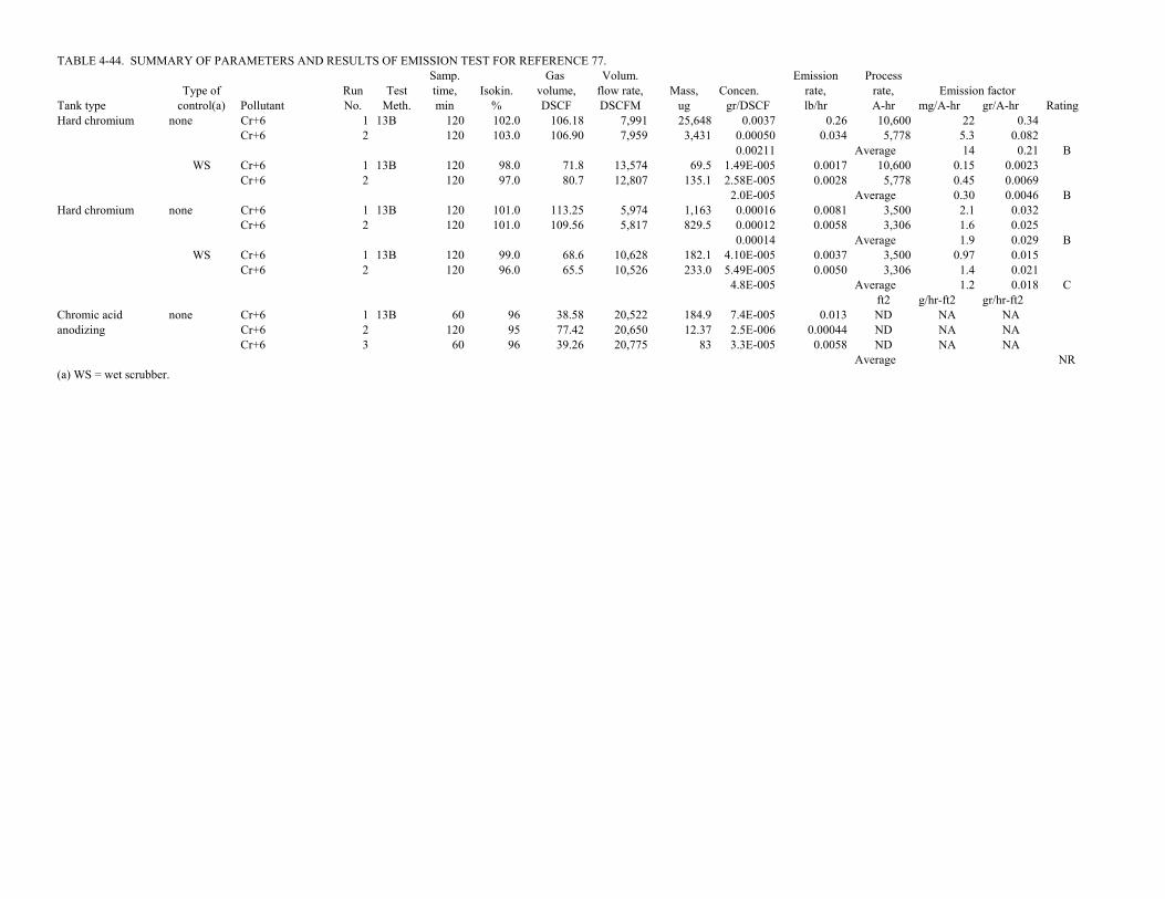
TABLE 4-44. SUMMARY OF PARAMETERS AND RESULTS OF EMISSION TEST FOR REFERENCE 77.Samp. Gas Volum. Emission Process
Type of Run Test time, Isokin. volume, flow rate, Mass, Concen. rate, rate, Emission factorTank type control(a) Pollutant No. Meth. min % DSCF DSCFM ug gr/DSCF lb/hr A-hr mg/A-hr gr/A-hr RatingHard chromium none Cr+6 1 13B 120 102.0 106.18 7,991 25,648 0.0037 0.26 10,600 22 0.34
Cr+6 2 120 103.0 106.90 7,959 3,431 0.00050 0.034 5,778 5.3 0.0820.00211 Average 14 0.21 B
WS Cr+6 1 13B 120 98.0 71.8 13,574 69.5 1.49E-005 0.0017 10,600 0.15 0.0023Cr+6 2 120 97.0 80.7 12,807 135.1 2.58E-005 0.0028 5,778 0.45 0.0069
2.0E-005 Average 0.30 0.0046 BHard chromium none Cr+6 1 13B 120 101.0 113.25 5,974 1,163 0.00016 0.0081 3,500 2.1 0.032
Cr+6 2 120 101.0 109.56 5,817 829.5 0.00012 0.0058 3,306 1.6 0.0250.00014 Average 1.9 0.029 B
WS Cr+6 1 13B 120 99.0 68.6 10,628 182.1 4.10E-005 0.0037 3,500 0.97 0.015Cr+6 2 120 96.0 65.5 10,526 233.0 5.49E-005 0.0050 3,306 1.4 0.021
4.8E-005 Average 1.2 0.018 Cft2 g/hr-ft2 gr/hr-ft2
Chromic acid none Cr+6 1 13B 60 96 38.58 20,522 184.9 7.4E-005 0.013 ND NA NAanodizing Cr+6 2 120 95 77.42 20,650 12.37 2.5E-006 0.00044 ND NA NA
Cr+6 3 60 96 39.26 20,775 83 3.3E-005 0.0058 ND NA NAAverage NR
(a) WS = wet scrubber.

4-97
TABLE 4-45. SUMMARY OF PARAMETERS AND RESULTS OF EMISSION TESTS FOR REFERENCE 78

TABLE 4-45. SUMMARY OF PARAMETERS AND RESULTS OF EMISSION TEST FOR REFERENCE 78.Samp. Gas Volum. Emission Process
Type of Run Test time, Isokin. volume, flow rate, Mass, Concen. rate, rate, Emission factorTank type control(a) Pollutant No. Meth. min % DSCF DSCFM ug gr/DSCF lb/hr ft2 mg/hr-m2 gr/hr-ft2 RatingMagnesium none total Cr 1 CARB 264 99.8 104.51 20,900 6.00 8.86E-007 0.00016 102 0.0076 0.011anodizing total Cr 2 425 144 97.4 114.27 21,300 13.00 1.76E-006 0.00032 102 0.015 0.022
total Cr 3 144 99.1 21,300 6.10 0.00015 102 0.0070 0.010Average 1.32E-006 0.010 0.014 CCr+6 1 CARB 264 99.8 104.51 20,900 5.00 7.38E-007 0.00013 102 0.0063 0.0091Cr+6 2 425 144 97.4 114.27 21,300 5.10 6.89E-007 0.00013 102 0.0060 0.0086Cr+6 3 144 99.1 21,300 1.20 2.9E-005 102 0.0014 0.0020Average 7.14E-007 0.0046 0.0066 NR
WS total Cr 1 CARB 264 99.2 103.94 21,100 1.00 1.48E-007 2.7E-005 102 0.0013 0.0018total Cr 2 425 144 97.8 128.87 21,000 1.00 1.20E-007 2.2E-005 102 0.0010 0.0015total Cr 3 144 99.7 136.33 21,800 1.00 1.13E-007 2.1E-005 102 0.0010 0.0015Average 1.27E-007 0.0011 0.0016 CCr+6 1 CARB 264 99.2 103.94 21,100 5.60 8.31E-007 1.5E-004 102 0.0072 0.0103Cr+6 2 425 144 97.8 128.87 21,000 1.20 1.44E-007 2.6E-005 102 0.0012 0.0018Cr+6 3 144 99.7 136.33 21,800 3.10 3.51E-007 6.6E-005 102 0.0031 0.0045Average 4.42E-007 0.0039 0.0055 NR
(a) WS = wet scrubber.
Pages 20 and 21 missing from report

4-98
TABLE 4-46. SUMMARY OF PARAMETERS AND RESULTS OF EMISSION TESTS FOR REFERENCE 81

TABLE 4-46. SUMMARY OF PARAMETERS AND RESULTS OF EMISSION TEST FOR REFERENCE 81.Samp. Gas Volum. Emission Process
Type of Run Test time, Isokin. volume, flow rate, Mass, Concen. rate, rate, Emission factorTank type control(a) Pollutant No. Meth. min % DSCF DSCFM ug gr/DSCF lb/hr A-hr mg/A-hr gr/A-hr RatingHard WS Cr+6 1 CARB 120 102.7 82.80 8,100 11.21 2.1E-006 0.00015 8,126 0.016 0.00025chromium Cr+6 2 425 120 99.3 74.60 8,100 8.92 1.8E-006 0.00013 8,000 0.015 0.00022
Cr+6 3 120 101.5 80.70 7,970 9.87 1.9E-006 0.00013 8,168 0.014 0.000221.94E-006 Average 0.015 0.00023 B
Total Cr 1 CARB 120 102.7 82.80 8,100 15.62 2.91E-006 0.00020 8,126 0.023 0.00035Total Cr 2 425 120 99.3 74.60 8,100 17.14 3.55E-006 0.00025 8,000 0.028 0.00043Total Cr 3 120 101.5 80.70 7,970 12.43 2.38E-006 0.00016 8,168 0.018 0.00028
2.94E-006 Average 0.023 0.00035 B(a) WS = wet scrubber.

4-99
TABLE 4-47. SUMMARY OF PARAMETERS AND RESULTS OF EMISSION TESTS FOR REFERENCE 83

TABLE 4-47. SUMMARY OF PARAMETERS AND RESULTS OF EMISSION TEST FOR REFERENCE 83.Samp. Gas Volum. Emission Process
Type of Run Test time, Isokin. volume, flow rate, Mass, Concen. rate, rate, Emission factorTank type control(a) Pollutant No. Meth. min % DSCF DSCFM ug gr/DSCF lb/hr ft2 mg/hr-m2 gr/hr-ft2 RatingChromic acid PBS/FS total Cr 1 CARB 120 97.4 95.00 46,840 0.69 1.12E-007 4.5E-005 73 0.0030 0.0043anodizing total Cr 2 425 120 99.9 101.80 48,950 1.16 1.76E-007 7.4E-005 73 0.0050 0.0071(C2) total Cr 3 120 98.8 94.90 46,140 0.48 7.81E-008 3.1E-005 73 0.0021 0.0030
Average 1.22E-007 0.0034 0.0048 BCr+6 1 CARB 120 97.4 95.00 46,840 0.11 1.79E-008 7.2E-006 73 0.00048 0.00069Cr+6 2 425 120 99.9 101.80 48,950 0.14 2.12E-008 8.9E-006 73 0.00060 0.00086Cr+6 3 120 98.8 94.90 46,140 0.11 1.79E-008 7.1E-006 73 0.00048 0.00068Average 1.90E-008 0.00052 0.00075 B
Chromic acid PBS/FS total Cr 1 CARB 120 99.7 124.70 1,018 23.70 2.93E-006 2.6E-005 31 0.0040 0.0057anodizing total Cr 2 425 120 95.3 103.70 963 17.00 2.53E-006 2.1E-005 31 0.0033 0.0047(Helo Blade) total Cr 3 120 97.7 106.90 968 4.80 6.93E-007 5.7E-006 31 0.00090 0.0013
total Cr 4 120 99.8 113.70 1,010 43.90 5.96E-006 5.2E-005 31 0.0080 0.012Average 3.03E-006 0.0040 0.0058 DCr+6 1 CARB 120 99.7 124.70 1,018 21.60 2.67E-006 2.3E-005 31 0.0036 0.0052Cr+6 2 425 120 95.3 103.70 963 11.90 1.77E-006 1.5E-005 31 0.0023 0.0033Cr+6 3 120 97.7 106.90 968 3.39 4.89E-007 4.1E-006 31 0.00063 0.00091Cr+6 4 120 99.8 113.70 1,010 30.70 4.17E-006 3.6E-005 31 0.0056 0.0081Average 2.28E-006 0.0030 0.0044 D
(a) PBS/FS = packed bed scrubber and fume suppressant.

4-100
TABLE 4-48. SUMMARY OF PARAMETERS AND RESULTS OF EMISSION TESTS FOR REFERENCE 84

TABLE 4-48. SUMMARY OF PARAMETERS AND RESULTS OF EMISSION TEST FOR REFERENCE 84.Samp. Gas Volum. Emission Process
Type of Run Test time, Isokin. volume, flow rate, Mass, Concen. rate, rate, Emission factorTank type control(a) Pollutant No. Meth. min % DSCF DSCFM ug gr/DSCF lb/hr ft2 mg/hr-m2 gr/hr-ft2 RatingChromic acid PBS/ Total Cr 1 CARB 120 93.0 98.9 668 3.72 5.8E-007 3.32E-006 31 0.00052 0.00074anodizing MPME Total Cr 2 425 120 100.2 85.7 699 2.36 4.2E-007 2.55E-006 31 0.00040 0.00057
Total Cr 3 120 98.7 86.9 720 1.38 2.5E-007 1.51E-006 31 0.00024 0.000344.17E-007 Average 0.00038 0.00055 B
Cr+6 1 CARB 120 93.0 98.9 668 3.72 5.8E-007 3.32E-006 31 0.00052 0.00074Cr+6 2 425 120 100.2 85.7 699 2.96 5.3E-007 3.19E-006 31 0.00050 0.00071Cr+6 3 120 98.7 86.9 720 0.69 1.2E-007 7.56E-007 31 0.00012 0.00017
4.12E-007 Average 0.00038 0.00054 B(a) PBS/MPME = packed bed scrubber and mesh pad mist eliminator.

4-101
TABLE 4-49. SUMMARY OF PARAMETERS AND RESULTS OF EMISSION TESTS FOR REFERENCE 85
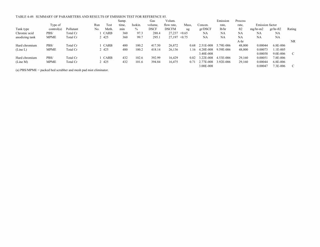
TABLE 4-49. SUMMARY OF PARAMETERS AND RESULTS OF EMISSION TEST FOR REFERENCE 85.Samp. Gas Volum. Emission Process
Type of Run Test time, Isokin. volume, flow rate, Mass, Concen. rate, rate, Emission factorTank type control(a) Pollutant No. Meth. min % DSCF DSCFM ug gr/DSCF lb/hr ft2 mg/hr-m2 gr/hr-ft2 RatingChromic acid PBS/ Total Cr 1 CARB 360 97.3 288.4 27,237 <0.65 NA NA NA NA NAanodizing tank MPME Total Cr 2 425 360 99.7 295.1 27,197 <0.75 NA NA NA NA NA
A-hr NRHard chromium PBS/ Total Cr 1 CARB 480 100.2 417.50 26,872 0.68 2.51E-008 5.79E-006 48,000 0.00044 6.8E-006(Line L) MPME Total Cr 2 425 480 100.2 418.14 26,136 1.16 4.28E-008 9.59E-006 48,000 0.00073 1.1E-005
3.40E-008 0.00058 9.0E-006 CHard chromium PBS/ Total Cr 1 CARB 432 102.6 392.99 16,429 0.82 3.22E-008 4.53E-006 29,160 0.00051 7.8E-006(Line M) MPME Total Cr 2 425 432 101.6 394.84 16,475 0.71 2.77E-008 3.92E-006 29,160 0.00044 6.8E-006
3.00E-008 0.00047 7.3E-006 C(a) PBS/MPME = packed bed scrubber and mesh pad mist eliminator.

4-102
TABLE 4-50. SUMMARY OF PARAMETERS AND RESULTS OF EMISSION TESTS FOR REFERENCE 86

TABLE 4-50. SUMMARY OF PARAMETERS AND RESULTS OF EMISSION TEST FOR REFERENCE 86.Samp. Gas Volum. Emission Process
Type of Run Test time, Isokin. volume, flow rate, Mass, Concen. rate, rate, Emission factorTank type control(a) Pollutant No. Meth. min % DSCF DSCFM ug gr/DSCF lb/hr ft2 mg/hr-m2 gr/hr-ft2 RatingChromic acid PBS total Cr 1 CARB 120 103.0 100.00 46,860 23.09 3.56E-006 0.0014 73 0.096 0.14anodizing total Cr 2 425 120 102.0 98.40 46,570 13.50 2.12E-006 0.00085 73 0.057 0.082
total Cr 3 120 95.6 92.90 46,940 5.49 9.12E-007 0.00037 73 0.025 0.035Average 2.20E-006 0.059 0.085 BCr+6 1 CARB 120 103.0 100.00 46,860 2.30 3.55E-007 0.00014 73 0.0096 0.014Cr+6 2 425 120 102.0 98.40 46,570 2.70 4.23E-007 0.00017 73 0.011 0.016Cr+6 3 120 95.6 92.90 46,940 3.90 6.48E-007 0.00026 73 0.018 0.025Average 4.75E-007 0.013 0.018 B
Chromic acid PBS total Cr 2 CARB 120 101.5 107.30 856 2.60 3.74E-007 2.7E-006 31 0.00043 0.00061anodizing total Cr 3 425 120 98.9 105.50 955 3.96 5.79E-007 4.7E-006 31 0.00074 0.0011
total Cr 4 120 98.4 96.00 873 35.70 5.74E-006 4.3E-005 31 0.0067 0.0096Average 2.23E-006 0.0026 0.0038 CCr+6 2 CARB 120 101.5 107.30 856 0.86 1.24E-007 9.1E-007 31 0.00014 0.00020Cr+6 3 425 120 98.9 105.50 955 2.20 3.22E-007 2.6E-006 31 0.00041 0.00059Cr+6 4 120 98.4 96.00 873 27.20 4.37E-006 3.3E-005 31 0.0051 0.0073Average 1.61E-006 0.0019 0.0027 C
(a) PBS = packed bed scrubber.

4-103
TABLE 4-51. SUMMARY OF PARAMETERS AND RESULTS OF EMISSION TESTS FOR REFERENCE 88

TABLE 4-51. SUMMARY OF PARAMETERS AND RESULTS OF EMISSION TEST FOR REFERENCE 88.Samp. Gas Volum. Emission Process
Type of Run Test time, Isokin. volume, flow rate, Mass, Concen. rate, rate, Emission factorTank type control(a) Pollutant No. Meth. min % DSCF DSCFM ug gr/DSCF lb/hr A-hr mg/A-hr gr/A-hr RatingHard PBS/PC Total Cr 1 CARB 80 102.4 50.35 2,169 6.00 1.84E-006 3.4E-005 5,447 0.0038 5.9E-005chromium Total Cr 2 425 80 102.3 48.88 2,108 7.00 2.21E-006 4.0E-005 5,473 0.0044 6.8E-005
Total Cr 3 80 102.3 50.58 2,181 11.30 3.45E-006 6.4E-005 5,447 0.0072 0.000112.50E-006 Average 0.0051 7.9E-005 B
PBS/PC Cr+6 1 CARB 80 102.4 50.35 2,169 6.20 1.90E-006 3.5E-005 5,447 0.0039 6.1E-005Cr+6 2 425 80 102.3 48.88 2,108 7.90 2.49E-006 4.5E-005 5,473 0.0050 7.7E-005Cr+6 3 80 102.3 50.58 2,181 7.40 2.26E-006 4.2E-005 5,447 0.0047 7.2E-005
2.22E-006 Average 0.0045 7.0E-005 NR(a) PBS/PC = packed bed scrubber and polypropylene chips.

4-104
TABLE 4-52. SUMMARY OF PARAMETERS AND RESULTS OF EMISSION TESTS FOR REFERENCE 89

TABLE 4-52. SUMMARY OF PARAMETERS AND RESULTS OF EMISSION TEST FOR REFERENCE 89.Samp. Gas Volum. Emission Process
Type of Run Test time, Isokin. volume, flow rate, Mass, Concen. rate, rate, Emission factorTank type control(a) Pollutant No. Meth. min % DSCF DSCFM ug gr/DSCF lb/hr A-hr mg/A-hr gr/A-hr RatingHard PBS/PC Total Cr 1 CARB 80 ND 35.75 1,527 17.7 7.64E-006 0.00010 4,760 0.013 0.00020chromium Total Cr 2 425 80 ND 34.99 1,539 27.7 1.22E-005 0.00016 5,033 0.019 0.00030
Total Cr 3 80 ND 36.94 1,540 11.2 4.68E-006 6.2E-005 5,093 0.0073 0.000118.18E-006 Average 0.013 0.00020 C
PBS/PC Cr+6 1 CARB 80 ND 35.75 1,527 10.8 4.66E-006 6.1E-005 4,760 0.0078 0.00012Cr+6 2 425 80 ND 34.99 1,539 6.2 2.73E-006 3.6E-005 5,033 0.0043 6.7E-005Cr+6 3 80 ND 36.94 1,540 11.1 4.64E-006 6.1E-005 5,093 0.0073 0.00011
4.01E-006 Average 0.0065 0.00010 NR(a) PBS/PC = packed bed scrubber and polypropylene chips.

4-105
TABLE 4-53. SUMMARY OF PARAMETERS AND RESULTS OF EMISSION TESTS FOR REFERENCE 90

TABLE 4-53. SUMMARY OF PARAMETERS AND RESULTS OF EMISSION TEST FOR REFERENCE 90.Samp. Gas Volum. Emission Process
Type of Run Test time, Isokin. volume, flow rate, Mass, Concen. rate, rate, Emission factorTank type control(a) Pollutant No. Meth. min % DSCF DSCFM ug gr/DSCF lb/hr A-hr mg/A-hr gr/A-hr RatingHard PB/PS Cr+6 1 13B 128 109.2 101.57 2,324 18,590 0.0028 0.056 10,182 5.3 0.083chromium Cr+6 2 128 109.0 93.32 2,138 16,266 0.0027 0.049 8,388 5.7 0.088
0.0028 Average 5.5 0.085 BPBS/ME/ Cr+6 1 13B 128 92.4 82.9 2,140 59.2 1.10E-005 0.00020 10,182 0.019 0.00030PB/PS Cr+6 2 128 94.2 83.6 2,118 22.8 4.20E-006 7.6E-005 8,388 0.0088 0.00014
7.62E-006 Average 0.014 0.00022 C(a) PB = polypropylene balls; PS = plastic sheet; PBS = packed bed scrubber; ME = moisture extractor.

4-106
TABLE 4-54. SUMMARY OF PARAMETERS AND RESULTS OF EMISSION TESTS FOR REFERENCE 93

TABLE 4-54. SUMMARY OF PARAMETERS AND RESULTS OF EMISSION TEST FOR REFERENCE 93.Samp. Gas Volum. Emission Process
Type of Run Test time, Isokin. volume, flow rate, Mass, Concen. rate, rate, Emission factorTank type control(a) Pollutant No. Meth. min % DSCF DSCFM ug gr/DSCF lb/hr A-hr mg/A-hr gr/A-hr RatingHard PBS/FS Total Cr 1 CARB 120 100.8 93.23 10,670 16.7 2.76E-006 0.00025 3,800 0.060 0.00093chromium Total Cr 2 425 120 100.9 93.80 10,719 9.0 1.48E-006 0.00014 3,800 0.032 0.00050
Total Cr 3 120 101.1 93.99 10,718 2.9 4.76E-007 4.4E-005 3,800 0.010 0.000161.57E-006 Average 0.034 0.00053 B
PBS/FS Cr+6 1 CARB 120 100.8 93.23 10,670 2.0 3.31E-007 3.0E-005 3,800 0.0072 0.00011Cr+6 2 425 120 100.9 93.80 10,719 1.3 2.14E-007 2.0E-005 3,800 0.0047 7.2E-005Cr+6 3 120 101.1 93.99 10,718 4.7 7.72E-007 7.1E-005 3,800 0.017 0.00026
4.39E-007 Average 0.0096 0.00015 NR(a) PBS/FS = packed bed scrubber and fume suppressant.

4-107
TABLE 4-55. SUMMARY OF PARAMETERS AND RESULTS OF EMISSION TESTS FOR REFERENCE 94

TABLE 4-55. SUMMARY OF PARAMETERS AND RESULTS OF EMISSION TEST FOR REFERENCE 94.Samp. Gas Volum. Emission Process
Type of Run Test time, Isokin. volume, flow rate, Mass, Concen. rate, rate, Emission factorTank type control(a) Pollutant No. Meth. min % DSCF DSCFM ug gr/DSCF lb/hr ft2 mg/hr-m2 gr/hr-ft2 RatingChromic acid none Total Cr 1 CARB 360 100.7 264.20 24,300 15,285 0.00089 0.186 352 2.6 3.7anodizing Total Cr 2 425 240 101.7 173.4 23,690 4,161 0.00037 0.075 352 1.0 1.5
Total Cr 3 120 102.3 89.30 24,270 2,438 0.00042 0.088 352 1.2 1.70.00056 Average 1.6 2.3 B
Cr+6 1 CARB 360 100.7 264.2 24,300 14,092 0.00082 0.171 352 2.4 3.4Cr+6 2 425 240 101.7 173.4 23,690 4,239 0.00038 0.077 352 1.1 1.5Cr+6 3 120 102.3 89.3 24,270 2,203 0.00038 0.079 352 1.1 1.6
0.00053 Average 1.5 2.2 BPBS/ Total Cr 1 CARB 360 94.2 302.30 23,340 5.07 2.6E-007 5.2E-005 352 0.00072 0.0010HEPA Total Cr 2 425 240 97.1 213.2 23,950 BDL NA NA 352 NA NA
Total Cr 3 120 100.6 116.3 25,230 BDL NA NA 352 NA NAAverage 0.00072 0.0010 D
Cr+6 1 CARB 360 94.2 302.3 23,340 2.57 1.3E-007 2.6E-005 352 0.00036 0.00052Cr+6 2 425 240 97.1 213.2 23,950 1.66 1.2E-007 2.5E-005 352 0.00034 0.00049Cr+6 3 120 100.6 116.3 25,230 0.73 9.7E-008 2.1E-005 352 0.00029 0.00042
1.2E-007 Average 0.00033 0.00048 B(a) PBS/HEPA = packed bed scrubber and high efficiency particulate air filter.

4-108
TABLE 4-56. SUMMARY OF PARAMETERS AND RESULTS OF EMISSION TESTS FOR REFERENCE 95

TABLE 4-56. SUMMARY OF PARAMETERS AND RESULTS OF EMISSION TEST FOR REFERENCE 95.Samp. Gas Volum. Emission Process
Type of Run Test time, Isokin. volume, flow rate, Mass, Concen. rate, rate, Emission factorTank type control(a) Pollutant No. Meth. min % DSCF DSCFM ug gr/DSCF lb/hr ft2 mg/hr-m2 gr/hr-ft2 RatingChromic acid none Total Cr 1 CARB 180 100 147.3 8,397 7,400 0.00078 0.056 176 1.5 2.2anodizing Total Cr 2 425 180 100 147.3 8,395 6,200 0.00065 0.047 176 1.3 1.9
Total Cr 3 180 100 146.3 8,336 6,100 0.00064 0.046 176 1.3 1.80.00069 Average 1.4 2.0 C
Cr+6 1 CARB 180 100 147.3 8,397 6,000 0.00063 0.045 176 1.3 1.8Cr+6 2 425 180 100 147.3 8,395 5,400 0.00057 0.041 176 1.1 1.6Cr+6 3 180 100 146.3 8,336 5,300 0.00056 0.040 176 1.1 1.6
0.00058 Average 1.2 1.7 CPBS/ Total Cr 1 CARB 180 97 183.5 8,160 BDL NA NA 176 NA NAHEPA Total Cr 2 425 180 98 181.2 8,013 BDL NA NA 176 NA NA
Total Cr 3 180 97 179.2 7,958 BDL NA NA 176 NA NAAverage NR
Cr+6 1 CARB 180 97 183.5 8,160 BDL NA NA 176 NA NACr+6 2 425 180 98 181.2 8,013 8.0 6.8E-007 4.7E-005 176 0.0013 0.0019Cr+6 3 180 97 179.2 7,958 BDL NA NA 176 NA NA
Average 0.0013 0.0019 NR(a) PBS/HEPA = packed bed scrubber and high efficiency particulate air filter.

4-109
TABLE 4-57. SUMMARY OF TEST DATA FOR ELECTROPLATING
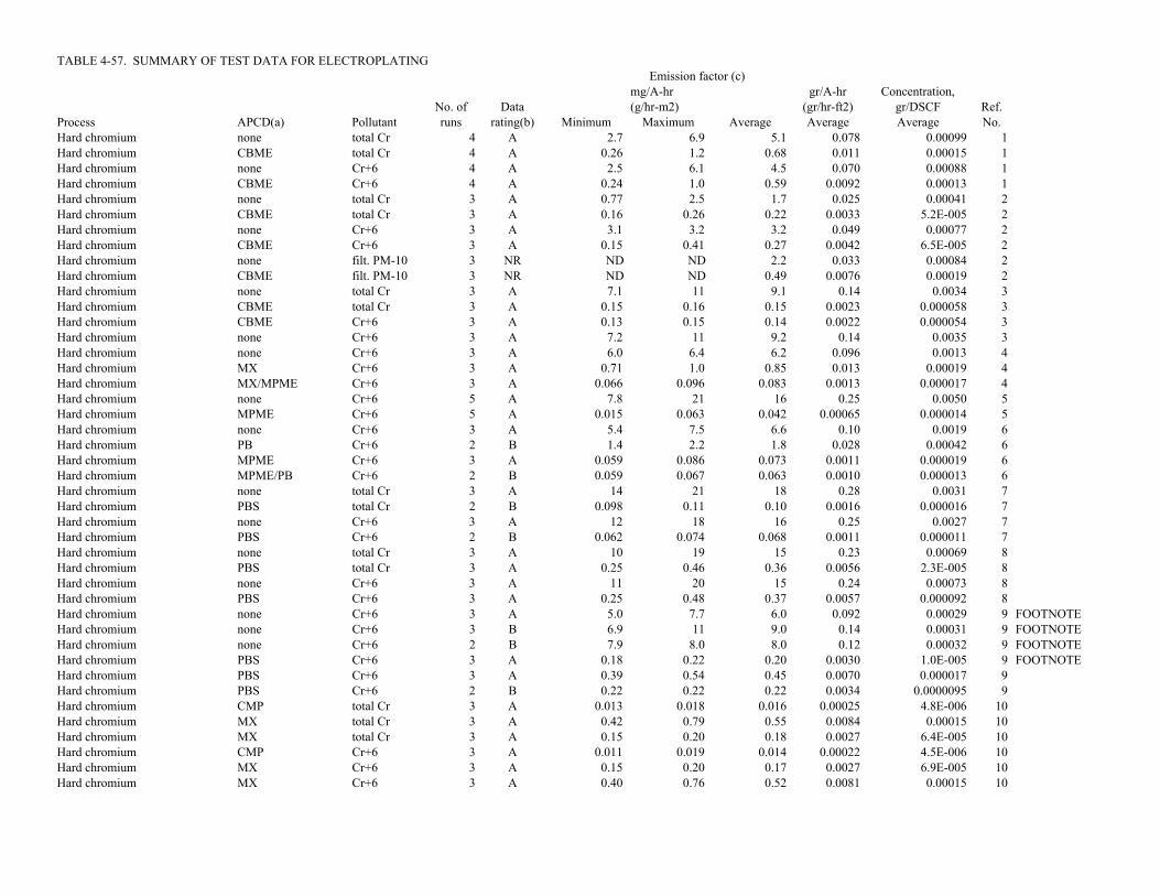
TABLE 4-57. SUMMARY OF TEST DATA FOR ELECTROPLATING Emission factor (c)mg/A-hr gr/A-hr Concentration,
No. of Data (g/hr-m2) (gr/hr-ft2) gr/DSCF Ref.Process APCD(a) Pollutant runs rating(b) Minimum Maximum Average Average Average No.Hard chromium none total Cr 4 A 2.7 6.9 5.1 0.078 0.00099 1Hard chromium CBME total Cr 4 A 0.26 1.2 0.68 0.011 0.00015 1Hard chromium none Cr+6 4 A 2.5 6.1 4.5 0.070 0.00088 1Hard chromium CBME Cr+6 4 A 0.24 1.0 0.59 0.0092 0.00013 1Hard chromium none total Cr 3 A 0.77 2.5 1.7 0.025 0.00041 2Hard chromium CBME total Cr 3 A 0.16 0.26 0.22 0.0033 5.2E-005 2Hard chromium none Cr+6 3 A 3.1 3.2 3.2 0.049 0.00077 2Hard chromium CBME Cr+6 3 A 0.15 0.41 0.27 0.0042 6.5E-005 2Hard chromium none filt. PM-10 3 NR ND ND 2.2 0.033 0.00084 2Hard chromium CBME filt. PM-10 3 NR ND ND 0.49 0.0076 0.00019 2Hard chromium none total Cr 3 A 7.1 11 9.1 0.14 0.0034 3Hard chromium CBME total Cr 3 A 0.15 0.16 0.15 0.0023 0.000058 3Hard chromium CBME Cr+6 3 A 0.13 0.15 0.14 0.0022 0.000054 3Hard chromium none Cr+6 3 A 7.2 11 9.2 0.14 0.0035 3Hard chromium none Cr+6 3 A 6.0 6.4 6.2 0.096 0.0013 4Hard chromium MX Cr+6 3 A 0.71 1.0 0.85 0.013 0.00019 4Hard chromium MX/MPME Cr+6 3 A 0.066 0.096 0.083 0.0013 0.000017 4Hard chromium none Cr+6 5 A 7.8 21 16 0.25 0.0050 5Hard chromium MPME Cr+6 5 A 0.015 0.063 0.042 0.00065 0.000014 5Hard chromium none Cr+6 3 A 5.4 7.5 6.6 0.10 0.0019 6Hard chromium PB Cr+6 2 B 1.4 2.2 1.8 0.028 0.00042 6Hard chromium MPME Cr+6 3 A 0.059 0.086 0.073 0.0011 0.000019 6Hard chromium MPME/PB Cr+6 2 B 0.059 0.067 0.063 0.0010 0.000013 6Hard chromium none total Cr 3 A 14 21 18 0.28 0.0031 7Hard chromium PBS total Cr 2 B 0.098 0.11 0.10 0.0016 0.000016 7Hard chromium none Cr+6 3 A 12 18 16 0.25 0.0027 7Hard chromium PBS Cr+6 2 B 0.062 0.074 0.068 0.0011 0.000011 7Hard chromium none total Cr 3 A 10 19 15 0.23 0.00069 8Hard chromium PBS total Cr 3 A 0.25 0.46 0.36 0.0056 2.3E-005 8Hard chromium none Cr+6 3 A 11 20 15 0.24 0.00073 8Hard chromium PBS Cr+6 3 A 0.25 0.48 0.37 0.0057 0.000092 8Hard chromium none Cr+6 3 A 5.0 7.7 6.0 0.092 0.00029 9 FOOTNOTEHard chromium none Cr+6 3 B 6.9 11 9.0 0.14 0.00031 9 FOOTNOTEHard chromium none Cr+6 2 B 7.9 8.0 8.0 0.12 0.00032 9 FOOTNOTEHard chromium PBS Cr+6 3 A 0.18 0.22 0.20 0.0030 1.0E-005 9 FOOTNOTEHard chromium PBS Cr+6 3 A 0.39 0.54 0.45 0.0070 0.000017 9Hard chromium PBS Cr+6 2 B 0.22 0.22 0.22 0.0034 0.0000095 9Hard chromium CMP total Cr 3 A 0.013 0.018 0.016 0.00025 4.8E-006 10Hard chromium MX total Cr 3 A 0.42 0.79 0.55 0.0084 0.00015 10Hard chromium MX total Cr 3 A 0.15 0.20 0.18 0.0027 6.4E-005 10Hard chromium CMP Cr+6 3 A 0.011 0.019 0.014 0.00022 4.5E-006 10Hard chromium MX Cr+6 3 A 0.15 0.20 0.17 0.0027 6.9E-005 10Hard chromium MX Cr+6 3 A 0.40 0.76 0.52 0.0081 0.00015 10

TABLE 4-57. (Continued) Emission factor (c)mg/A-hr gr/A-hr Concentration,
No. of Data (g/hr-m2) (gr/hr-ft2) gr/DSCF Ref.Process APCD(a) Pollutant runs rating(b) Minimum Maximum Average Average Average No.Hard chromium none total Cr 3 A 5.3 6.9 6.1 0.094 0.00042 11Hard chromium CMP total Cr 3 A 0.063 0.090 0.079 0.0012 5.0E-006 11Hard chromium FS/CMP total Cr 3 A 0.033 0.056 0.041 0.00064 0.0000035 11Hard chromium FS total Cr 3 A 1.1 2.6 1.8 0.027 0.00016 11Hard chromium none total Cr 3 A 36 120 69 1.1 0.030 12Hard chromium PBS/CMP total Cr 3 A 0.0023 0.0060 0.0042 6.4E-005 2.7E-006 12Hard chromium none Cr+6 3 A 39 130 74 1.1 0.032 12Hard chromium PBS/CMP Cr+6 3 A 0.0023 0.0061 0.0041 6.3E-005 2.6E-006 12Hard chromium none total Cr 6 A 1.6 17 6.0 0.093 0.0012 13Hard chromium none Cr+6 6 A 1.5 12 4.6 0.070 0.00089 13Hard chromium none total Cr 3 A 1.5 1.8 1.7 0.026 0.00073 14Hard chromium FS/PB total Cr 3 A 0.033 0.042 0.037 0.00057 1.6E-005 14Hard chromium PBS total Cr 3 A 0.062 0.082 0.072 0.0011 0.000026 14Hard chromium PBS/FS/PB total Cr 3 A 0.0073 0.011 0.0096 0.00015 3.7E-006 14Decorative chromium none total Cr 3 A 1.4 2.0 1.7 0.027 0.00063 15Decorative chromium none Cr+6 3 A 1.5 2.3 1.9 0.030 0.00070 15Decorative chromium none Cr+6 3 A 1.2 1.4 1.3 0.021 0.00040 16Decorative chromium FS Cr+6 3 A 0.0050 0.010 0.0067 0.00010 2.0E-006 16Decorative chromium FS Cr+6 3 A 0.0015 0.0046 0.0029 4.5E-005 0.00000093 16Trivalent chromium none total Cr 3 NR 0.035 0.15 0.084 0.0013 1.2E-005 17Trivalent chromium none Cr+6 3 NR 0.0083 0.015 0.011 0.00017 1.6E-006 17Trivalent chromium none Cr+3 3 NR 0.025 0.14 0.073 0.0011 1.0E-005 17Trivalent chromium none CO2 3 NR 250 300 280 610 NA 17Hard chromium none total Cr 2 C 3.7 4.0 3.8 0.059 0.00025 20Hard chromium MPME total Cr 2 B 0.26 0.30 0.28 0.0043 2.1E-006 20Chromic acid anodizing MPME total Cr 2 D 0.0020 0.0050 0.0035 0.0051 2.0E-007 20Hard chromium FS/MPME total Cr 2 B 0.29 0.31 0.30 0.0047 2.3E-006 20Hard chromium FS total Cr 2 C 0.19 0.27 0.23 0.0036 0.000015 20Cyanide-copper MPME cyanide 3 C 19 65 47 0.73 2.7E-006 20Cadmium MPME cyanide 3 C 70 210 160 2.4 0.00010 20Cadmium MPME cadmium 2 C 0.29 0.29 0.29 0.0045 1.5E-007 20Cadmium PBS total Cr 3 NR 0.22 0.76 0.40 0.0062 7.4E-007 21Cadmium PBS Cd 3 D 0.083 1.0 0.50 0.077 9.3E-007 21Cadmium PBS NH3 3 D 12 29 23 0.35 4.2E-005 21Cadmium PBS CN 3 D 14 41 32 0.49 5.9E-005 21Hard chromium none total Cr 2 D 0.14 0.16 0.15 0.0023 0.0000012 22Hard chromium PBS total Cr 2 D 0.14 0.14 0.14 0.0022 0.0000011 22Hard chromium none total Cr 2 D 4.8 9.3 7.0 0.11 0.00068 23Hard chromium none total Cr 2 D 5.6 6.2 5.9 0.091 0.00063 23Hard chromium PBS total Cr 2 D 0.0054 0.041 0.023 0.00036 2.0E-006 23Hard chromium PBS total Cr 1 NR NA NA 0.017 0.00026 9.3E-007 23Hard chromium none Cr+6 2 D 5.0 5.3 5.1 0.079 0.00054 23Hard chromium none Cr+6 2 D 4.2 13 8.8 0.14 0.00084 23Hard chromium PBS/FBME total Cr 3 NR 0.00024 0.0019 0.00083 1.3E-005 7.1E-008 24Hard chromium PBS/FBME total Cr 3 NR 0.00016 0.0012 0.00050 7.7E-006 6.8E-008 24

TABLE 4-57. (Continued) Emission factor (c)mg/A-hr gr/A-hr Concentration,
No. of Data (g/hr-m2) (gr/hr-ft2) gr/DSCF Ref.Process APCD(a) Pollutant runs rating(b) Minimum Maximum Average Average Average No.Hard chromium none total Cr 6 A 4.5 12 7.1 0.11 0.0016 25Hard chromium FS/PB total Cr 6 A 0.13 0.30 0.19 0.0030 0.000046 25Hard chromium none Cr+6 6 A 3.5 12 6.0 0.092 0.0014 25Hard chromium FS/PB Cr+6 6 A 0.10 0.26 0.16 0.0024 3.8E-005 25Hard chromium none total Cr 6 A 2.3 11 7.5 0.12 0.0018 26 3.171470306Hard chromium FS/PB total Cr 6 A 0.054 0.17 0.11 0.0017 2.9E-005 26Hard chromium none Cr+6 6 A 2.0 11 7.1 0.11 0.0017 26Hard chromium FS/PB Cr+6 5 A 0.086 0.14 0.11 0.0017 3.0E-005 26Decorative chromium none total Cr 6 A 2.5 6.4 4.3 0.067 0.00021 27Decorative chromium FS total Cr 4 A 0.0066 0.035 0.016 0.00025 9.3E-007 27Decorative chromium none Cr+6 6 A 2.3 4.4 3.6 0.055 0.00018 27Decorative chromium none total Cr 6 A 0.58 2.4 1.0 0.016 0.00018 28Decorative chromium FS total Cr 5 A 0.0037 0.012 0.0092 0.00014 1.1E-006 28Decorative chromium none Cr+6 6 A 0.16 2.1 0.94 0.014 0.00016 28Hard chromium none Cr+6 3 D 8.6 47 34 0.53 0.0071 29Chromic acid anodizing none total Cr 6 A 0.11 1.5 0.64 0.92 0.000044 30Chromic acid anodizing FS total Cr 6 A 0.014 0.076 0.050 0.072 3.4E-006 30Chromic acid anodizing FS/PB total Cr 6 A 0.012 0.023 0.018 0.026 1.2E-006 30Chromic acid anodizing none Cr+6 6 A 0.080 1.1 0.50 0.71 3.4E-005 30Chromic acid anodizing FS Cr+6 6 A 0.0087 0.037 0.025 0.036 1.7E-006 30Chromic acid anodizing FS/PB Cr+6 6 A 0.0075 0.019 0.013 0.019 9.1E-007 30Hard chromium none total Cr 3 B 2.0 5.0 3.5 0.055 0.00027 31Hard chromium MPME total Cr 3 B 0.12 0.18 0.15 0.0024 1.1E-005 31Hard chromium none filt. PM 3 NR 330 450 390 6.0 0.027 33Hard chromium MPME filt. PM 3 NR 57 71 65 1.0 0.0047 33Hard chromium none total Cr 3 D 71 88 79 1.2 0.0055 33Hard chromium MPME total Cr 3 D 16 21 18 0.28 0.0013 33Decorative chromium FS/PBS filt. PM 1 NR 2.6 2.6 2.6 0.040 0.00011 58Decorative chromium FS filt. PM 3 NR 0.91 5.3 3.4 0.052 0.00036 58Decorative chromium FS/PBS total Cr 3 NR 9.1 12 10 0.16 0.00089 58Decorative chromium FS total Cr 3 NR 0.034 0.055 0.047 0.00073 4.7E-006 58Decorative chromium FS total Cr 3 NR 2.2 9.6 6.5 0.10 0.00067 58Decorative chromium FS/PBS Cr+6 3 NR 1.3 2.0 1.7 0.027 0.00015 58Decorative chromium FS Cr+6 3 NR 0.51 2.5 1.6 0.025 0.00017 58Decorative chromium FS Cr+6 3 NR 0.010 0.013 0.011 0.00017 1.1E-006 58Hard chromium none filt. PM 3 NR 16 23 19 0.29 0.0028 59Hard chromium PBS filt. PM 3 NR 10 14 11 0.17 0.0013 59Hard chromium none total Cr 3 NR 3.3 5.7 4.6 0.071 0.00067 59Hard chromium PBS total Cr 3 NR 0.21 0.45 0.35 0.0054 4.2E-005 59Hard chromium none Cr+6 3 NR 1.5 2.7 2.2 0.034 0.00032 59Hard chromium PBS Cr+6 3 NR 0.084 0.11 0.095 0.0015 1.1E-005 59Chromic acid anodizing none total Cr 2 B 0.91 1.4 1.2 1.7 0.00024 62Chromic acid anodizing FS total Cr 2 B 0.046 0.068 0.057 0.082 1.1E-005 62Chromic acid anodizing none Cr+6 2 B 0.55 0.91 0.73 1.0 0.00015 62

TABLE 4-57. (Continued) Emission factor (c)mg/A-hr gr/A-hr Concentration,
No. of Data (g/hr-m2) (gr/hr-ft2) gr/DSCF Ref.Process APCD(a) Pollutant runs rating(b) Minimum Maximum Average Average Average No.Chromic acid anodizing none total Cr 3 B 1.1 4.7 3.4 4.8 0.00026 63Chromic acid anodizing FS total Cr 2 C 0.011 0.041 0.026 0.037 1.8E-006 63Chromic acid anodizing FS total Cr 3 NR NA NA 0.0050 0.0072 3.5E-007 63Chromic acid anodizing FS/PB total Cr 2 C 0.0056 0.027 0.016 0.023 1.1E-006 63Chromic acid anodizing PB total Cr 2 B 1.1 1.3 1.2 1.7 0.000095 63Chromic acid anodizing none Cr+6 3 B 1.0 4.0 2.9 4.2 0.00023 63Copper none copper 1 NR 23 23 23 0.36 0.0000072 67Copper WS copper 3 C 160 1100 700 11 0.000081 67Nickel none nickel 3 B 11 110 57 0.88 4.0E-005 67Nickel WS nickel 3 B 4.5 13 8.4 0.13 0.0000057 67Nickel none nickel 3 C 8.6 34 25 0.38 0.000022 67Nickel WS nickel 3 B 4.8 15 11 0.17 0.0000076 67Cadmium none cadmium 3 C 0.17 5.0 1.8 0.028 0.000013 67Cadmium WS cadmium 3 B 0.14 0.40 0.25 0.0038 0.0000024 67Cadmium none cadmium 3 C 0.56 6.0 3.4 0.052 0.0000037 67Cadmium WS cadmium 3 C 0.41 28 11 0.17 0.0000073 67Chromium metal prod. PBS total Cr 3 B 0.054 0.35 0.18 0.0028 0.00010 71Chromium metal prod. PBS Cr+6 3 B 0.044 0.12 0.080 0.0012 0.000045 71Hard chromium none Cr+6 3 C 1.1 1.1 1.1 0.018 0.000069 74Chromic acid anodizing none total Cr 3 A 0.22 0.27 0.25 0.35 3.1E-005 75Chromic acid anodizing none Cr+6 3 A 0.19 0.24 0.22 0.31 2.7E-005 75Chromic acid anodizing WS total Cr 3 A 0.015 0.020 0.017 0.025 2.7E-006 75Chromic acid anodizing WS Cr+6 3 B 0.00062 0.010 0.0056 0.0081 8.8E-007 75Hard chromium none Cr+6 2 B 5.3 22 14 0.21 0.0021 77Hard chromium WS Cr+6 2 B 0.15 0.45 0.30 0.0046 2.0E-005 77Hard chromium none Cr+6 2 B 1.6 2.1 1.9 0.029 0.00014 77Hard chromium WS Cr+6 2 B 0.97 1.4 1.2 0.018 0.000048 77Magnesium anodizing none total Cr 2 C 0.0076 0.015 0.010 0.014 1.3E-006 78Magnesium anodizing none Cr+6 3 NR 0.0014 0.0063 0.0046 0.0066 0.00000071 78Magnesium anodizing WS total Cr 3 C 0.0010 0.0013 0.0011 0.0016 0.000000127 78Magnesium anodizing WS Cr+6 3 NR 0.0012 0.0072 0.0039 0.0055 0.000000442 78Hard chromium WS total Cr 3 B 0.014 0.016 0.015 0.00023 0.0000019 81Hard chromium WS Cr+6 3 B 0.018 0.028 0.023 0.00035 0.0000029 81Chromic acid anodizing PBS/FS total Cr 3 B 0.0021 0.0050 0.0034 0.0048 1.2E-007 83Chromic acid anodizing PBS/FS Cr+6 3 B 0.00048 0.00060 0.00052 0.00075 1.9E-008 83Chromic acid anodizing PBS/FS total Cr 4 D 0.00090 0.0080 0.0040 0.0058 3.0E-006 83Chromic acid anodizing PBS/FS Cr+6 4 D 0.00063 0.0056 0.0030 0.0044 2.3E-006 83Chromic acid anodizing PBS/MPME total Cr 4 B 0.00024 0.00052 0.00038 0.00055 0.00000042 84Chromic acid anodizing PBS/MPME Cr+6 4 B 0.00012 0.00052 0.00038 0.00054 0.00000041 84Hard chromium PBS/MPME total Cr 2 C 0.00044 0.00073 0.00058 9.0E-006 3.4E-008 85Hard chromium PBS/MPME total Cr 2 C 0.00044 0.00051 0.00047 7.3E-006 3.0E-008 85
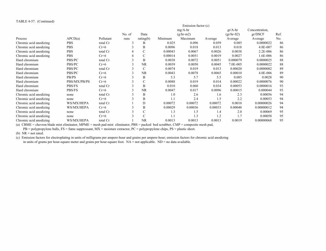
TABLE 4-57. (Continued) Emission factor (c)mg/A-hr gr/A-hr Concentration,
No. of Data (g/hr-m2) (gr/hr-ft2) gr/DSCF Ref.Process APCD(a) Pollutant runs rating(b) Minimum Maximum Average Average Average No.Chromic acid anodizing PBS total Cr 3 B 0.025 0.096 0.059 0.085 0.0000022 86Chromic acid anodizing PBS Cr+6 3 B 0.0096 0.018 0.013 0.018 4.8E-007 86Chromic acid anodizing PBS total Cr 4 C 0.00043 0.0067 0.0026 0.0038 2.2E-006 86Chromic acid anodizing PBS Cr+6 4 C 0.00014 0.0051 0.0019 0.0027 1.6E-006 86Hard chromium PBS/PC total Cr 3 B 0.0038 0.0072 0.0051 0.000079 0.0000025 88Hard chromium PBS/PC Cr+6 3 NR 0.0039 0.0050 0.0045 7.0E-005 0.0000022 88Hard chromium PBS/PC total Cr 3 C 0.0074 0.019 0.013 0.00020 0.0000082 89Hard chromium PBS/PC Cr+6 3 NR 0.0043 0.0078 0.0065 0.00010 4.0E-006 89Hard chromium PB/PS Cr+6 3 B 5.3 5.7 5.5 0.085 0.0028 90Hard chromium PBS/MX/PB/PS Cr+6 3 C 0.0088 0.019 0.014 0.00022 0.0000076 90Hard chromium PBS/FS total Cr 3 B 0.010 0.060 0.034 0.00053 0.0000016 93Hard chromium PBS/FS Cr+6 3 NR 0.0047 0.017 0.0096 0.00015 0.000044 93Chromic acid anodizing none total Cr 3 B 1.0 2.6 1.6 2.3 0.00056 94Chromic acid anodizing none Cr+6 3 B 1.1 2.4 1.5 2.2 0.00053 94Chromic acid anodizing WS/MX/HEPA total Cr 1 D 0.00072 0.00072 0.00072 0.0010 0.00000026 94Chromic acid anodizing WS/MX/HEPA Cr+6 3 B 0.00029 0.00036 0.00033 0.00048 0.00000012 94Chromic acid anodizing none total Cr 3 C 1.3 1.5 1.4 2.0 0.00069 95Chromic acid anodizing none Cr+6 3 C 1.1 1.3 1.2 1.7 0.00058 95Chromic acid anodizing WS/MX/HEPA total Cr 1 NR 0.0013 0.0013 0.0013 0.0019 0.00000068 95(a) CBME = chevron blade mist eliminator, MPME = mesh pad mist eliminator, PBS = packed bed scrubber, CMP = composite mesh pad, PB = polypropylene balls, FS = fume suppressant, MX = moisture extractor, PC = polypropylene chips, PS = plastic sheet.(b) NR = not rated.(c) Emission factors for electroplating in units of milligrams per ampere-hour and grains per ampere-hour; emission factors for chromic acid anodizing in units of grams per hour-square meter and grains per hour-square foot. NA = not applicable. ND = no data available.
4-116
TABLE 4-58. SUMMARY OF CANDIDATE EMISSION FACTORS FORCHROMIUM ELECTROPLATING

TABLE 4-58. SUMMARY OF CANDIDATE EMISSION FACTORS FOR CHROMIUM ELECTROPLATINGNo. of Emission factor(c)
APCD(a) Pollutant(b) tests mg/A-hr gr/A-hr mg/DSCM gr/DSCF Rating ReferencesHARD CHROMIUM ELECTROPLATINGnone chromium compounds 19 7.8 0.12 NA NA B 1-9,11,13-14,25-26,31,77MX chromium compounds 3 0.51 0.0079 0.31 0.00014 D 4,10PB chromium compounds 1 1.8 0.028 0.96 0.00042 D 6FS chromium compounds 1 1.8 0.027 0.37 0.00016 D 11FS/PB chromium compounds 3 0.11 0.0018 0.069 3.0E-005 D 14,25-26PBS chromium compounds 9 0.18 0.0027 0.047 2.1E-005 C 7-9,14,71,77,81PBS/FS/PB chromium compounds 3 0.016 0.00025 0.0059 2.6E-006 D 14,88,93CBME chromium compounds 3 0.35 0.0054 0.20 8.8E-005 D 1-3MPME chromium compounds 7 0.13 0.0020 0.028 1.2E-005 D 4-6,20,31PBS/MPME chromium compounds 2 0.00053 0.0000082 0.000073 3.2E-008 E 85CMP chromium compounds 4 0.026 0.00040 0.0087 3.8E-006 D 10-12
total PM/PM-10 (d) NA 2.1Cr 2.1Cr 2.1Cr 2.1Cr DDECORATIVE CHROMIUM ELECTROPLATINGnone chromium compounds 4 2.1 0.033 NA NA D 15-16,27-28FS chromium compounds 4 0.010 0.00015 0.0027 1.2E-006 D 16,27-28
total PM/PM-10 (d) NA 2.1Cr 2.1Cr 2.1Cr 2.1Cr DCHROMIC ACID ANODIZING
g/hr-m2 gr/hr-ft2none chromium compounds 5 1.4 2.0 NA NA D 30,62-63,75,94PB chromium compounds 1 1.2 1.7 NA NA D 63FS chromium compounds 3 0.044 0.064 NA NA D 30,62-63FS/PB chromium compounds 2 0.017 0.025 NA NA D 30,63PBS chromium compounds 3 0.0068 0.0096 NA NA D 75,86PBS/FS chromium compounds 1 0.00052 0.00075 NA NA D 83MPME chromium compounds 1 0.0035 0.0051 NA NA E 20PBS/MPME chromium compounds 1 0.00038 0.00054 NA NA D 84WS/MX/HEPA chromium compounds 1 0.00033 0.00048 NA NA D 94
total PM/PM-10 (d) NA 2.1Cr 2.1Cr NA NA D(a) MX = moisture extractor, FS = fume suppressant, PB = polypropylene balls, PBS = packed bed scrubber, WS = wet scrubber, CBME = chevron blade mist eliminator, MPME = mesh-pad mist eliminator, CMP = composite mesh pad, HEPA = high efficiency particulate air filter.(b) Emissions comprised of hexavalent chromium.(c) Emission factors for controlled emissions from electroplating presented based on total energy input and as concentration.(d) Factors for total PM can be estimated as the ratio of the mass of chromic acid to the mass of chromium times the corresponding emission factor for chromium compounds. Because emissions consist of a mist, the total PM factors also can be used to estimate emissions of PM-10.

4-117
TABLE 4-59. SUMMARY OF CANDIDATE EMISSION FACTORS FORELECTROPLATING--OTHER METALS
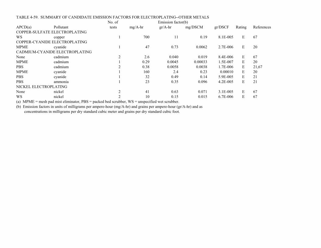
TABLE 4-59. SUMMARY OF CANDIDATE EMISSION FACTORS FOR ELECTROPLATING--OTHER METALSNo. of Emission factor(b)
APCD(a) Pollutant tests mg/A-hr gr/A-hr mg/DSCM gr/DSCF Rating ReferencesCOPPER-SULFATE ELECTROPLATINGWS copper 1 700 11 0.19 8.1E-005 E 67COPPER-CYANIDE ELECTROPLATINGMPME cyanide 1 47 0.73 0.0062 2.7E-006 E 20CADMIUM-CYANIDE ELECTROPLATINGNone cadmium 2 2.6 0.040 0.019 8.4E-006 E 67MPME cadmium 1 0.29 0.0045 0.00033 1.5E-007 E 20PBS cadmium 2 0.38 0.0058 0.0038 1.7E-006 E 21,67MPME cyanide 1 160 2.4 0.23 0.00010 E 20PBS cyanide 1 32 0.49 0.14 5.9E-005 E 21PBS ammonia 1 23 0.35 0.096 4.2E-005 E 21NICKEL ELECTROPLATINGNone nickel 2 41 0.63 0.071 3.1E-005 E 67WS nickel 2 10 0.15 0.015 6.7E-006 E 67(a) MPME = mesh pad mist eliminator, PBS = packed bed scrubber, WS = unspecified wet scrubber.(b) Emission factors in units of milligrams per ampere-hour (mg/A-hr) and grains per ampere-hour (gr/A-hr) and as concentrations in milligrams per dry standard cubic meter and grains per dry standard cubic foot.
4-118
TABLE 4-60. SUMMARY OF CANDIDATE EMISSION FACTORS FORELECTROPLATING--OTHER METALS

TABLE 4-60. SUMMARY OF STATISICAL ANALYSES OF EMISSION DATAHard Hard Hard Hard Cr acid
Type of plating chromium chromium chromium chromium anodizingControl method none PBS PBS/FS MPME noneEmission factor units gr/A-hr gr/dscf gr/dscf gr/dscf gr/hr-ft2No. of emission tests 19 9 5 7 5Minimum value 0.025 2.9E-006 1.6E-006 2.1E-006 0.29Maximum value 0.28 0.000045 0.0000082 0.000019 4.8Mean value 0.12 1.9E-005 4.7E-006 1.1E-005 2.0Standard deviation 0.074 1.2E-005 3.0E-006 6.7E-006 1.7Variance 0.0547 1.5E-010 9.0E-012 4.5E-011 3.0Standard error 0.017 4.1E-006 1.3E-006 2.5E-006 0.7895% Confidence interval Minimum 0.085 9.4E-006 9.9E-007 5.0E-006 0.0 Maximum 0.16 2.8E-005 8.5E-006 1.7E-005 4.1

4-119
REFERENCES FOR SECTION 4
1. Chromium Electroplaters Test Report: Greensboro Industrial Platers, Greensboro, NC. EntropyEnvironmentalists, Inc., Research Triangle Park, NC. Prepared for U. S. Environmental ProtectionAgency, Research Triangle Park, NC. EMB Report 86-CEP-1. March 1986.
2. Chromium Electroplaters Test Report: Consolidated Engravers Corporation, Charlotte, NC. PeerConsultants, Inc., Rockville, MD. Prepared for U. S. Environmental Protection Agency, ResearchTriangle Park, NC. EMB Report 87-CEP-9. May 1987.
3. Chromium Electroplaters Test Report: Able Machine Company, Taylors, SC. PEI Associates, Inc.,Cincinnati, OH. Prepared for U. S. Environmental Protection Agency, Research Triangle Park, NC. EMB Report 86-CEP-3. June 1986.
4. Chromium Electroplaters Test Report: Roll Technology Corporation, Greenville, SC. PeerConsultants, Dayton, OH. Prepared for U. S. Environmental Protection Agency, Research TrianglePark, NC. EMB Report 88-CEP-13. August 1988.
5. Chromium Electroplaters Test Report: Precision Machine and Hydraulic, Inc., Worthington, WV. Peer Consultants, Dayton, OH. Prepared for U. S. Environmental Protection Agency, ResearchTriangle Park, NC. EMB Report 88-CEP-14. September 1988.
6. Chromium Electroplaters Test Report: Hard Chrome Specialists, York, PA. Peer Consultants,Dayton, OH. Prepared for U. S. Environmental Protection Agency, Research Triangle Park, NC. EMB Report-89-CEP-15. January 1989.
7. Chromium Electroplaters Test Report: Piedmont Industrial Platers, Statesville, NC. EntropyEnvironmentalists, Inc., Research Triangle Park, NC. Prepared for U. S. Environmental ProtectionAgency, Research Triangle Park, NC. EMB Report 86-CEP-04. September 1986.
8. Chromium Electroplaters Test Report: Steel Heddle, Inc., Greenville, SC. PEI Associates, Inc.,Cincinnati, OH. Prepared for U. S. Environmental Protection Agency, Research Triangle Park, NC. EMB Report 86-CEP-2. June 1986.
9. Chromium Electroplaters Test Report: Fusion, Inc., Houston, TX. Peer Consultants, Inc., Dayton,OH. Prepared for U. S. Environmental Protection Agency, Research Triangle Park, NC. EMBReport 89-CEP-16. May 1989.
10. Hexalavent Chromium Emission Test Report: Precision Engineering, Seattle, WA. AdvancedSystems Technology, Atlanta, GA. Prepared for U. S. Environmental Protection Agency, ResearchTriangle Park, NC. EMB Report 91-CEP-18. December 1991.
11. Emission Test Report: Emission Test Results for Total Chromium Inlet and Outlet of the SouthFume Scrubber. Monroe Auto Equipment, Hartwell, GA. IEA, Research Triangle Park, NC. ReportNo. 192-92-25. February 1992.

4-120
12. Chromium Electroplaters Emission Test Report: Remco Hydraulics, Inc., Willits, CA. AdvancedSystems Technology, Atlanta, GA. Prepared for U. S. Environmental Protection Agency, ResearchTriangle Park, NC. EMB Report 91-CEP-17. June 1991.
13. NESHAP Screening Method Chromium, Emission Test Report, Roll Technology Corporation,Greenville, SC, EMB Report No. 87-CEP-6, U. S. Environmental Protection Agency, ResearchTriangle Park, NC. September 1987.
14. Chromium Electroplating Emissions Comparison Test: Electric Chromic and Grinding Company,Santa Fe Springs, CO. Prepared for U. S. Environmental Protection Agency, Research Triangle Park,NC. EMB Report 91-CEP-20. February 1992.
15. Chromium Electroplaters Test Report: GMC Delco Products Division, Livonia, MI. PeerConsultants, Inc., Dayton, OH. Prepared for U. S. Environmental Protection Agency, ResearchTriangle Park, NC. EMB Report 89-CEP-7. March 1987.
16. Chromium Electroplaters Test Report: Automatic Die Casting Specialties, Inc., St. Clair Shores,MI. Prepared for U. S. Environmental Protection Agency, Research Triangle Park, NC. EMB Report89-CEP-11. April 1988.
17. Trivalent Chromium Emission Test Report: True Temper Sports, Seneca, SC. Prepared for U. S.Environmental Protection Agency, Research Triangle Park, NC. EMB Report 92-CEP-21. June 1992.
18. Memo from Barker, B., MRI, to Vervaert, A., EPA/ISB. Engineering Analysis--Reliable Plating andPolishing Company. May 15, 1987.
19. NEESA 2-158A, Chromium Emissions from Chromic Acid Anodizing Operations at Building 167,Naval Aviation Depot, Naval Air Station, Hanida, CA. Naval Energy and Environmental SupportActivity. Port Hueneme, CA. March 1990.
20. NEESA 2-165, Chromium, Cyanide, and Cadmium Emission Tests Results. Building 604 PlatingFacility. Source Identification 10-PEN17008406. Naval Aviation Depot, Pensacola. Naval Energyand Environmental Support Activity. Port Hueneme, CA. January 1991.
21. Charles K. Yee, Source Emissions Tests at Buildings 604 and 3557 at Naval Air Rework Facility,Pensacola, Florida, Navy Environmental Support Office, Port Hueneme, CA. September 1980.
22. Emissions Testing Conducted For Viron International at Alameda Naval Air Station onNovember 30 - December 13, 1990, TMA Thermo Analytical, Inc., Richmond, CA. January 24,1991.
23. Chromium and Hexavalent Chromium Emissions Results Conducted For Viron International onNovember 27 - December 5, 1990, TMA Thermo Analytical, Inc., Richmond, CA. December 27,1990.
4-121
24. David J. Cook, and Drek A. Newton, Chromium Emission Tests Results, Building 32 PlatingFacility, BAAQMD Authority to Construct: 574, Naval Aviation Depot, Alameda, Naval Energy andEnvironmental Support Activity, Port Hueneme, CA. May 1991.
25. Test Results for Fume Suppressant Certification, M&T Chemical's Fumetrol 101 in Hard ChromePlating Tanks, Pacific Environmental Services, Inc., Arcadia, CA. November 1, 1989.
26. Test Results for Fume Suppressant Certification, OMI International Corporation's Foam-Lok L inHard Chrome Plating Tanks, Pacific Environmental Services, Inc., Arcadia, CA. November 17,1989.
27. Test Results for Fume Suppressant Certification, McGean Rohco's Dis Mist NP in DecorativeChrome Plating Tanks, Pacific Environmental Services, Inc., Arcadia, CA. March 16, 1990.
28. Test Results for Fume Suppressant Certification, Omi International's Zero-Mist in DecorativeChrome Plating Tanks, Pacific Environmental Services, Inc., Arcadia, CA. July 13, 1990.
29. Determination of the Efficiency of a Mesh-pad Mist Eliminator Using the Constant Rate SamplingMethod, ChromeTech, Inc., Macedonia, OH. November 15, 1990.
30. Test Results for Fume Suppressant Certification, Autochem, Inc., M&T's Fumetrol 101 in ChromeAnodizing Tanks, Pacific Environmental Services, Inc., Arcadia, CA. March 1990.
31. William E. Powers and Seth Forester, Source Emission Testing of the Building 195 Plating Shop atNorfolk Naval Shipyard, Portsmouth, VA, 11-18 March 1985, Naval Energy and EnvironmentalSupport Activity, Port Hueneme, CA. May 1985.
32. Emissions Testing Conducted For Viron International at Alameda Naval Air Station on December 6,1990 - January 4, 1991, TMA Thermo Analytical, Inc., Richmond, CA. February 15, 1991.
33. Source Test Report, Naval Air Rework Facility, Norfolk Naval Air Station, Chrome Line 1 Demister,November 22, 1986, Environmental Source Samplers, Inc., Charlotte, NC. December 1986.
34. Emissions Test Report. SVS/MECA™ at A Chromic Anodizing Facility, Santa Ana, CA, onDecember 12, 1988 by Truesdart Laboratories, Inc. Tustin, CA. Report Dated January 11, 1989.
35. Emissions Stack Testing at McDonnell Douglas, Torrance, CA. Source Tested: Etching TankScrubber (Tank 193, Bldg. 2), Anodizing Tank Scrubber (Tank 195, Bldg 2). Date Tested: October 1 and 3, 1986. Prepared for Lathana and Watkins, Attorneys at Law. Prepared byEngineering-Science, Pasadena, CA. Revised November 12, 1986.
36. NEESA 2-119, September 1984 (Naval Energy and Environmental Support Activity, Port Huenana,CA) Source Emission Testing and Industrial Ventilation Survey of Bldg. 210 Plating Shop at LongBeach Naval Shipyard, Long Beach, CA. May 7-June 2, 1984.
37. NEESA 2-157a, Chromium Emissions from Chromic Plating and Chromic Acid AnodizingOperations at Bldg. 5, Naval Aviation Depot, Naval Air Station, Alameda, CA. March 1990.

4-122
38. State of California Air Resources Board Test of Standard Nickel-Chromium Plating Company - TestReport C-86-085. April 6, 1987.
39. South Coast (AQMD), Source Test Report: 86-0513. Conducted at Standard Plating Co., LosAngeles, CA. Hexavalent Chromium Emitted from a Wet Scrubber Control Chromic Plating,Tank #50. Tested November 5, 1986. Issued January 27, 1987.
40. Emissions Stack Testing, Tarby, Inc., Huntington Beach, CA. Source Tested: Chromic Plating TankExhaust Scrubber. Date Tested: December 11, 1986. Prepared by Engineering Science, Pasadena,CA. January 12, 1987.
41. Source Test Report of a CM&E Demonstration Unit Serving a Hard Chromic Plating Tank atElectrolyzing Inc., 1947 Hooper Avenue, Los Angeles, CA 90011. Conducted for the MetalFinishing Association of Southern California by Pacific Environmental Services, Inc., Arcadia, CA. January 25, 1989.
42. Source Test Report of a Tri-Mar Corporation Unit Serving a Hard Chrome Plating Tank at ChromePlating Company, 1748 Workman Street, Los Angeles, CA 90031. Conducted for the MetalFinishing Association of Southern California. Prepared by Pacific Environmental Services, Inc.,Arcadia, CA. February 28, 1989.
43. Source Test Report of a Monsanto Enviro-Chem Demonstration Unit Serving a Hard ChromePlating Tank at Electronic Chrome and Grinding Co., Inc. 9218-32 Dice Road, Santa Fe Springs,CA 90670. Conducted by Metal Finishing Association of Southern California. Prepared by PacificEnvironmental Services, Arcadia, CA. January 23, 1989.
44. Source Test Report of Ceco Filters Demonstration Unit Serving a Hard Chrome Plating Tank atChrome Plating Company, 1748 Workman Street, Los Angeles, CA. Conducted by Metal FinishingAssociation of Southern California. Prepared by Pacific Environmental Services, Arcadia, CA. March 1, 1989.
45. State of California Air Resources Board. Chrome Plating Company. Total and HexavalentChromium Emissions from Chromium Plating Tanks 3 and 4. Engineering Evaluation Branch TestReport. C-86-125. Report Dated April 3, 1987.
46. Particulate and Chromic Acid Emission Evaluation, Process Stack, Consolidated Engravers Corp.,Chester, SC. July 1983, Job Number 3294-1, Prepared by David & Floyd, Inc. Greenwood, SC.
47. Embee Plating Test, 2136 South Hathaway, Santa Ana, CA 92705. Prepared by EnvironmentalResearch Group, Inc. Ann Arbor, MI. April 11, 1986.
48. Chevrolet Livonia Bumper Plant No. 4 Heil Evaporator. Tested by the Chevrolet Central Office ofEnvironmental Engineering Department. Tested September 24, 1979.
49. Source Test of Intermetro Industries, 9393 Arrow Highway, Cucamonga, CA. Prepared by TruesdailLaboratories, Inc. Tested on February 24, 1980. Prepared on April 5, 1988.
4-123
50. Source Test of Parmaco Pacific, Inc., 1101 W. Strick Avenue, Orange, CA. Conducted on June 9,1987. By Truesdail Laboratories, Inc. July 21, 1987.
51. California Air Resources Board Test of Price Pfister, Inc. Chromium Plating Tank #1. Total andHexavalent Chromium Emissions. Report No. C-86-106. April 3, 1987.
52. Source Test of Chrome Crankshaft Co., 6845 Florence Place, Bell Gardens, CA. Conducted onApril 2, 1987 by Truesdail Laboratories. April 30, 1987.
53. Source Test Report No. 87-0256 of Plato Products, Inc., 2120 East Allen Avenue, Glendora, CA. (Also called Source Test of Gresham, Varner, Savage, 600 North Arrowhead Avenue, SanBernandino, CA) Conducted by Truesdail Laboratories. July 29, 1987.
54. Air Pollution Potential from Electroplating Operations. Philip Diamond. Environmental HealthLaboratory. McClellan Air Force Base, CA. April 1969. Report No. 69M-15.
55. Inlet and Outlet of Scrubber at Standard Nickel Chromium Plating Company, Total and HexavalentChromium, Truesdail Laboratories, Tustin, CA. December 17, 1986.
56. Inlet and Outlet of Scrubber Serving Chrome Dip Tank, Particulate and Chromium RemovalEfficiencies, Truesdail Laboratories, Tustin, CA. April 11, 1986.
57. Wayne A. Nakagawa, Source Test Report 85-481, Conducted at Plato Products, Inc., 2120 E. AllenAve., Glendora, CA, Efficiency of, and Emissions From the Scrubber Serving a Hard ChromePlating Tank, South Coast Air Quality Management District, El Monte, CA. September 18, 1985.
58. NESHAP Screening Study Chromium, Emission Test Report, C.S. Ohm Manufacturing Company,Sterling Heights, MI, EMB Report No. 85-CHM-10, U. S. Environmental Protection Agency,Research Triangle Park, NC. December 1985.
59. NESHAP Screening Study Chromium, Emission Test Report, Carolina Plating Company, Greenville,SC, EMB Report No. 85-CHM-11, U. S. Environmental Protection Agency, Research Triangle Park,NC. December 1985.
60. Chromium Removal Performance Test, CECO Filter, Eastmount Engineering, Inc., Walpole, MA. April 15, 1992.
61. Source Emission Evaluation, Boeing Company, Plant 2, Chromic Acid Anodizing Tank 5A, Seattle,Washington, August-December 1989, AM Test, Inc., Redmond, WA. January 30, 1990.
62. Efficiency of Harshaw Chemical's MSP-ST For Controlling Chrome Emissions From a ChromicAcid Anodizing Tank, Pacific Environmental Services, Arcadia, CA. March 16, 1989.
63. Report of Hexavalent Chromium Emission Testing On The Chromic Acid Anodizing and Tri-AcidEtching Processes at Buildings 3 and 5, Douglas Aircraft Company, Long Beach, CA, Engineering-Science, Pasadena. CA, September 14, 1989.

4-124
64. Emissions Stack Testing at McDonnell Douglas, Torrance, CA, Engineering-Science, Pasadena, CA. November 12, 1986.
65. Report of Air Pollution Source Testing At Douglas Aircraft Company Tank No. 195 and TankNo. 245, Engineering-Science, Pasadena, CA. June 28, 1989.
66. Report of Air Pollution Source Testing At Building No. 5 Scrubbers (HA7-5, HA7-6), DouglasAircraft Company, Long Beach, California, Engineering-Science, Pasadena, CA, January 12, 1990.
67. Air Toxics Sampling Report Deutsch Engineered Connecting Devices, Oceanside, California,Kleinfelder, Inc., San Diego, CA, June 28, 1991
68. Nickel Compliance Emission Determination of the Packed Tower Evaporator, Compliance Testingfor Nickel Emissions for American Nickeloid Company, Walnutport, Pennsylvania, BCM, PlymouthMeeting, PA, June 1988.
69. Report to Snap-On Tools Corporation, Kenosha, Wisconsin for Stack Emission Tests, MedicalProducts Scrubber, July 20, 1990, Environmental Technology & Engineering Corporation, ElmGrove, WI, 1990.
70. Final Report: Bethlehem Steel Corporation Chrome Line Scrubber, BCM, Plymouth Meeting, PA,January 1992.
71. Emission Test Results for Chromium Emission Rate of the Scrubber inlet at the U.S. ChromeCorporation Facility, Batavia, New York, IEA, Research Triangle Park, NC, November 11, 1991.
72. Chromium and Hexavalent Chromium Emissions Testing, Del Manufacturing, Oxnard Facility,August 29-30, 1991, BTC Environmental, Inc., Ventura, CA, 1991.
73. Summary of Source Test Results, Chrome Plating Tanks S-2 and S-3, Francis Plating of Oakland,Report No. 90117, Bay Area Air Quality Management District, San Francisco, CA, February 15,1990.
74. Summary of Source Test Results, Scrubber Inlet from S-2 and S-3, Francis Plating of Oakland,Report No. 90118, Bay Area Air Quality Management District, San Francisco, CA, February 15,1989.
75. Source Test Report for Total Chromium and Hexavalent Chromium From Chromic Acid Anodizing,General Dynamics-Convair, Lindbergh Field Facility, Building #1, TEAM Environmental Services,Inc. San Marcos, CA, March 24, 1993.
76. Gravco, Inc., Scrubber Efficiency Evaluation Project, AirNova, Inc., Collingswood, NJ, November1989.
77. Source Emission Evaluation, Hytek Finishes Company, Chrome Abatement Equipment PerformanceEvaluation, Kent, Washington, May 18-19, 1989, Am Test, Inc., Redmond, WA, July 14, 1989
78. Source Test Report 5640-01, Lockheed Missiles and Space Company, Building 103, Tank 68, B. C.Analytical, Emeryville, CA, January 23, 1991.

4-125
79. Summary of Source Test Results, Mare Island Naval Shipyard, Plant #44, Source A436, Report No.88162, Bay Area Air Quality Management District, San Francisco, CA, May 9, 1988.
80. Summary of Source Test Results, Mare Island Naval Shipyard, Plant #44, Source A439, Report No.88163, Bay Area Air Quality Management District, San Francisco, CA, May 9, 1988.
81. Measurement of Hexavalent Chromium Emissions From Hard Chrome Plating Operations atMultichrome Company, Inc., Pacific Environmental Services, Inc., Baldwin Park, CA, January 29,1993.
82. NEESA 2-176, Chromium Emission Tests Results, Building 32 Plating Facility, BAAQMD Authorityto Construct: 574, Naval Aviation Depot, Alameda, Naval Energy and Environmental SupportActivity, Port Hueneme, CA, May 1991.
83. Measurement of Chromium Emissions From Chromic Acid Anodizing Operations in Building 2 atNaval Aviation Depot, North Island, San Diego, CA, Benmol Corporation, San Diego, CA, October29, 1991.
84. Measurement of Chromium Emissions From Chromic Acid Anodizing Operations in Building 2 atNaval Aviation Depot, San Diego, CA, Pacific Environmental Services, Inc., Baldwin Park, CA, April8, 1992.
85. NEESA 2-197, Chromium Emission Tests Results, Building 32 Plating Facility, BAAQMD Authorityto Construct: 574, Naval Aviation Depot, Alameda, Naval Energy and Environmental SupportActivity, Port Hueneme, CA, August 1992.
86. Measurement of Chromium Emissions From Chromic Acid Anodizing Operations in Building 2 atNaval Aviation Depot, San Diego, CA, Pacific Environmental Services, Inc., Baldwin Park, CA,August 15, 1991.
87. Naval Undersea Warfare Center Plating Plant, Building 72, Scrubber #3, Keyport, Washington,February 4, 1993, Am Test Air Quality, Inc., Preston, WA, March 3, 1993.
88. Compliance Test Procedure, Pacific Hard Chrome, Tests Conducted December 3, 1991, ChemicalData Management Systems, Dublin, CA, January 2, 1991.
89. Compliance Test Procedure, Pacific Hard Chrome, Tests Conducted July 18-19, 1991, ChemicalData Management Systems, Dublin, CA, June 1991.
90. Chromium Emissions Testing per PSAPCA Test Method Determination of Hexavalent ChromiumEmissions from Decorative and Hard Chrome Electroplating and Chromic Acid Anodizing, Report292690, Asko Processing, Inc., Chrome Plate Tank 1, Olympic Scientific, Inc., Seattle, WA,December 6, 1990.
91. Fume Scrubber Compliance Source Test Report, Amplica Incorporated, 950 Lawrence Drive,Newbury Park, CA 91320, Environmental Monitoring and Services, Inc., Camarillo, CA 93010, 1987.

4-126
92. Hexavalent Chromium Emissions, Armoloy of Ohio, April 13 and 14, 1994, Stilson Laboratories,Inc., Columbus, OH, May 26, 1994.
93. Compliance Test Results, Babbitt Bearing, Test Date May 27, 1992, Chemical Data ManagementSystems, Dublin, CA, 1992.
94. Source Test Measurement of Chromium Emissions From Chromic Acid Anodizing Tanks at BoeingFabrication, 700 15th Street, S.W., Auburn, WA, Pacific Environmental Services, Inc., Baldwin Park,CA, September 24, 1991.
95. Wright Schuchard Harbor Company, Boeing Commercial Airplane Company, Building 17-68,Chrome Anodizing Tank L-16, KCH Scrubber Inlet/Outlet, Auburn, Washington, May 9-10, 1991,Am Test Air Quality, Inc., Preston, WA, June 10, 1991.
96. Boeing Defense and Space Group, Plant II, Building 2-31, Fume Scrubber #3 Exhaust Stack, Seattle,Washington, August 19-20, 1991, Am Test Air Quality, Inc., Preston, WA, September 30, 1991.
97. Written correspondence from B. Sarven, Hayden Environmental Group, Inc., Miamisburg, Ohio, to J.Hilty, RAPCA, Dayton, Ohio, Results of test on Cascade Corporation Auto Chrome Line, March 1,1991.
98. Aydil, M. and R. King, Estimating Hexavalent Chromium Emissions From Electroless ChromiumConversion Coating Processes, Roy F. Weston, Santa Barbara, CA, May 1995.
99. Telephone communication from J. Baker, JMC (USA), Inc., Research Triangle Park, NC, to RichardMarinshaw, Midwest Research Institute, Cary, NC, April 30, 1996.

TABLE A-1. SUMMARY OF EMISSION FACTOR CALCULATIONS FOR HARD CHROMIUM ELECTROPLATING.Pollutant Data Available emission factors(c) Emission factors used(c) Factor
APCD(a) measured rating(b) mg/A-hr gr/A-hr gr/DSCF mg/DSCM mg/A-hr gr/A-hr gr/DSCF mg/DSCM rating Referencesnone Total Cr A 5.1 0.078 0.00099 2.3 5.1 0.078 0.00099 2.3 1none Total Cr A 1.7 0.025 0.00041 0.94 1.7 0.025 0.00041 0.94 2none Total Cr A 9.1 0.14 0.0034 7.8 9.1 0.14 0.0034 7.8 3none Cr+6 A 6.2 0.096 0.0013 3.0 6.2 0.096 0.0013 3.0 4none Cr+6 A 16 0.25 0.0050 11 16 0.25 0.0050 11 5none Cr+6 A 6.6 0.10 0.0019 4.3 6.6 0.10 0.0019 4.3 6none Total Cr A 18 0.28 0.0031 7.1 18 0.28 0.0031 7.1 7none Total Cr A 15 0.23 0.00069 1.6 15 0.23 0.00069 1.6 8none Cr+6 A 6.0 0.092 0.00029 0.66 6.0 0.092 0.00029 0.66 9 Fnone Total Cr A 6.1 0.094 0.00042 0.96 6.1 0.094 0.00042 0.96 11none Total Cr A 6.0 0.093 0.0012 2.6 6.0 0.093 0.0012 2.6 13none Total Cr A 1.7 0.026 0.00073 1.7 1.7 0.026 0.00073 1.7 14none Total Cr A 7.1 0.11 0.0016 3.8 7.1 0.11 0.0016 3.8 25none Total Cr A 7.5 0.12 0.0018 4.1 7.5 0.12 0.0018 4.1 26none Cr+6 B 8.0 0.12 0.00032 0.73 8.0 0.12 0.00032 0.73 9 Fnone Cr+6 B 9.0 0.14 0.00031 0.71 9.0 0.14 0.00031 0.71 9none Total Cr B 3.5 0.055 0.00027 0.62 3.5 0.055 0.00027 0.62 31none Cr+6 B 1.9 0.029 0.00014 0.32 1.9 0.029 0.00014 0.32 77none Cr+6 B 14 0.21 0.0021 4.8 14 0.21 0.0021 4.8 77none Cr+6 A 74 1.1 0.032 74 12none Total Cr C 3.8 0.059 0.00025 0.57 20none Cr+6 C 1.1 0.018 0.000069 0.16 74none Total Cr D 5.9 0.091 0.00063 1.4 23none Total Cr D 7.0 0.11 0.00068 1.6 23none Cr+6 D 34 0.53 0.0071 16 29none Total Cr D 79 1.2 0.0055 13 33
Total Cr NR 4.6 0.071 0.00067 1.5 59Candidate emission factor Average 7.8 0.12 0.0014 3.1 B 1-9,11,13-14,25-26,31,77
Minimum 1.65 0.025 0.00014 0.32 0Maximum 18.0 0.28 0.0050 11.44 0Std Dev. 4.77 0.0740 0.0013 2.97Rel Std Dev. 0.61 0.61 0.95 0.95Median 6.60 0.102 0.00099 2.27Geo Mean 6.3 0.098 0.00088 2.015th percentile 1.7 0.026 0.00026 0.5925th percentile 5.52 0.085 0.00037 0.8475th percentile 9.05 0.14 0.0018 4.2195th percentile 16.20 0.25 0.0036 8.15
MX Cr+6 A 0.85 0.013 0.00019 0.43 0.85 0.013 0.00019 0.43 4MX Cr+6 A 0.52 0.0081 0.00015 0.34 0.52 0.0081 0.00015 0.34 10MX Cr+6 A 0.17 0.0027 6.9E-005 0.16 0.17 0.0027 6.9E-005 0.16 10Candidate emission factor Average 0.51 0.0079 0.00014 0.31 D 4,10

TABLE A-1. (Continued)Pollutant Data Available emission factors(c) Emission factors used(c) Factor
APCD(a) measured rating(b) mg/A-hr gr/A-hr gr/DSCF mg/DSCM mg/A-hr gr/A-hr gr/DSCF mg/DSCM rating ReferencesPB Cr+6 B 1.8 0.028 0.00042 0.96 1.8 0.028 0.00042 0.96 6PB/PS Cr+6 B 5.5 0.085 0.0028 6.4 90Candidate emission factor 1.8 0.028 0.00042 0.96 D 6
FS Total Cr A 1.8 0.027 0.00016 0.37 1.8 0.027 0.00016 0.37 11FS Total Cr C 0.23 0.0036 0.000015 0.034 20Candidate emission factor 1.8 0.027 0.00016 0.37 D 11
FS/PB Total Cr A 0.037 0.00057 1.6E-005 0.037 0.037 0.00057 1.6E-005 0.037 14FS/PB Total Cr A 0.19 0.0030 4.6E-005 0.11 0.19 0.0030 4.6E-005 0.11 25FS/PB Total Cr A 0.11 0.0017 2.9E-005 0.065 0.11 0.0017 2.9E-005 0.065 26Candidate emission factor Average 0.11 0.0018 3.0E-005 0.069 D 14,25-26
PBS Total Cr A 0.36 0.0056 2.3E-005 0.052 0.36 0.0056 2.3E-005 0.052 8PBS Total Cr A 0.072 0.0011 2.6E-005 0.059 0.072 0.0011 2.6E-005 0.059 14PBS Cr+6 A 0.45 0.0070 1.7E-005 0.039 0.45 0.0070 1.7E-005 0.039 9PBS Cr+6 A 0.20 0.0030 1.0E-005 0.023 0.20 0.0030 1.0E-005 0.023 9 FPBS Cr+6 B 0.22 0.0034 9.5E-006 0.022 0.22 0.0034 9.5E-006 0.022 9PBS Total Cr B 0.10 0.0016 1.6E-005 0.037 0.10 0.0016 1.6E-005 0.037 7PBS Cr+6 A 0.080 0.0012 0.000045 0.10 0.080 0.0012 0.000045 0.10 71WS Cr+6 B 0.30 0.0046 2.0E-005 0.046 0.30 0.0046 2.0E-005 0.046 77WS Cr+6 B 0.023 0.00035 0.0000029 0.0066 0.023 0.00035 0.0000029 0.0066 81WS Cr+6 C 1.2 0.018 0.000048 0.11 77PBS Total Cr D 0.14 0.0022 1.1E-006 0.0025 22PBS Total Cr D 0.023 0.00036 2.0E-006 0.0046 23PBS Total Cr NR 0.35 0.0054 4.2E-005 0.095 59PBS Total Cr NR 0.017 0.00026 9.3E-007 0.0021 23Candidate emission factor Average 0.18 0.0027 2.1E-005 0.047 D 7-9,14,71,77,81
Minimum 0.023 0.00035 2.90E-006 0.0066Maximum 0.45 0.0070 4.50E-005 0.10Std Dev. 0.15 0.0023 1.22E-005 0.028Rel Std Dev. 0.83 0.84 5.88E-001 0.59Median 0.20 0.0030 1.70E-005 0.04Geo Mean 0.15 0.0022 1.51E-005 0.0345th percentile 0.043 0.00066 5.54E-006 0.01325th percentile 0.080 0.0012 1.00E-005 0.02375th percentile 0.30 0.0046 2.27E-005 0.05295th percentile 0.42 0.0064 3.74E-005 0.086
PBS/FS/PB Total Cr A 0.0096 0.00015 3.7E-006 0.0084 0.0096 0.00015 3.7E-006 0.0084 14PBS/PC Total Cr B 0.0051 0.000079 0.0000025 0.0057 0.0051 0.000079 0.0000025 0.0057 88PBS/FS Total Cr B 0.034 0.00053 0.0000016 0.0037 0.034 0.00053 0.0000016 0.0037 93PBS/PC Total Cr C 0.013 0.00020 0.0000082 0.019 89PBS/MX/PB/PS Cr+6 C 0.014 0.00022 0.0000076 0.017 90Candidate emission factor Average 0.016 0.00025 2.6E-006 0.0059 D 14,88,93

TABLE A-1. (Continued)Pollutant Data Available emission factors(c) Emission factors used(c) Factor
APCD(a) measured rating(b) mg/A-hr gr/A-hr gr/DSCF mg/DSCM mg/A-hr gr/A-hr gr/DSCF mg/DSCM rating ReferencesCBME Total Cr A 0.68 0.011 0.00015 0.35 0.68 0.011 0.00015 0.35 1CBME Total Cr A 0.22 0.0033 5.2E-005 0.12 0.22 0.0033 5.2E-005 0.12 2CBME Total Cr A 0.15 0.0023 5.8E-005 0.13 0.15 0.0023 5.8E-005 0.13 3Candidate emission factor Average 0.35 0.0054 8.8E-005 0.20 D 1-3
MPME Cr+6 A 0.042 0.00065 1.4E-005 0.032 0.042 0.00065 1.4E-005 0.032 5MPME Cr+6 A 0.073 0.0011 1.9E-005 0.043 0.073 0.0011 1.9E-005 0.043 6MPME Total Cr B 0.28 0.0043 2.1E-006 0.0047 0.28 0.0043 2.1E-006 0.0047 20MPME Total Cr B 0.15 0.0024 1.1E-005 0.025 0.15 0.0024 1.1E-005 0.025 31FS/MPME Total Cr B 0.30 0.0047 2.3E-006 0.0052 0.30 0.0047 2.3E-006 0.0052 20MX/MPME Cr+6 A 0.083 0.0013 1.7E-005 0.039 0.083 0.0013 1.7E-005 0.039 4MPME/PB Cr+6 B 0.063 0.0010 1.3E-005 0.030 0.063 0.0010 1.3E-005 0.030 6MPME Cr+6 B 0.080 0.0012 4.5E-005 0.10 71MPME Total Cr D 18 0.28 0.0013 3.0 33Candidate emission factor Average 0.13 0.0020 1.2E-005 0.028 D 4-6,20,31
Minimum 0.042 0.00065 2.05E-006 0.0047Maximum 0.30 0.0047 1.90E-005 0.043Std Dev. 0.11 0.0017 6.70E-006 0.015Rel Std Dev. 0.84 0.84 0.56 0.56Median 0.083 0.0013 1.30E-005 0.030Geo Mean 0.11 0.0017 8.43E-006 0.0195th percentile 0.048 0.00076 2.11E-006 0.004825th percentile 0.068 0.0011 6.68E-006 0.01575th percentile 0.22 0.0034 1.55E-005 0.03595th percentile 0.30 0.0046 1.84E-005 0.042
PBS/MPME Total Cr C 0.00058 9.0E-006 3.4E-008 7.8E-005 0.00058 9.0E-006 3.4E-008 7.8E-005 85PBS/MPME Total Cr C 0.00047 7.3E-006 3.0E-008 6.9E-005 0.00047 7.3E-006 3.0E-008 6.9E-005 85PBS/FBME Total Cr NR 0.00083 1.3E-005 7.1E-008 0.00016 24PBS/FBME Total Cr NR 0.00050 7.7E-006 6.8E-008 0.00015 24
Average 0.00053 8.2E-006 3.2E-008 7.3E-005 E 85
CMP Cr+6 A 0.014 0.00022 4.5E-006 0.010 0.014 0.00022 4.5E-006 0.010 10CMP Total Cr A 0.079 0.0012 5.0E-006 0.011 0.079 0.0012 5.0E-006 0.011 11FS/CMP Total Cr A 0.041 0.00064 3.5E-006 0.0080 0.041 0.00064 3.5E-006 0.0080 11PBS/CMP Cr+6 A 0.0041 6.3E-005 2.6E-006 0.0060 0.0041 6.3E-005 2.6E-006 0.0060 12Candidate emission factor Average 0.026 0.00040 3.8E-006 0.0087 D 10-12
Minimum 0.004 0.000063 2.61E-006 0.0060Maximum 0.079 0.0012 4.95E-006 0.011Std Dev. 0.033 0.00051 1.05E-006 0.002Rel Std Dev. 1.28 1.28 0.28 0.28Median 0.028 0.00043 4.01E-006 0.0092Geo Mean 0.021 0.00032 3.78E-006 0.00875th percentile 0.006 0.000087 2.74E-006 0.006325th percentile 0.012 0.00018 3.28E-006 0.007575th percentile 0.051 0.00078 4.63E-006 0.01195th percentile 0.073 0.0011 4.89E-006 0.011

TABLE A-1. (Continued)(a) CBME = chevron blade mist eliminator, MPME = mesh pad mist eliminator, PBS = packed bed scrubber, CMP = composite mesh pad, PB = polypropylene balls, FS = fume suppresant, MX = moisture extractor, WS = unspecified wet scrubber, PC = polypropylene chips.(b) NR = not rated.(c) Emission factors in units of milligrams per ampere-hour and grains per ampere-hour (uncontrolled and controlled) and as concentrations in milligrams per dry standard cubic meter and grains per dry standard cubic foot.
07/23/96
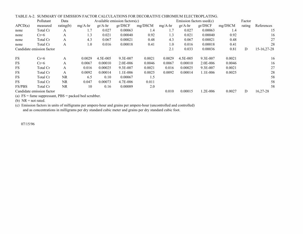
TABLE A-2. SUMMARY OF EMISSION FACTOR CALCULATIONS FOR DECORATIVE CHROMIUM ELECTROPLATING.Pollutant Data Available emission factors(c) Emission factors used(c) Factor
APCD(a) measured rating(b) mg/A-hr gr/A-hr gr/DSCF mg/DSCM mg/A-hr gr/A-hr gr/DSCF mg/DSCM rating Referencesnone Total Cr A 1.7 0.027 0.00063 1.4 1.7 0.027 0.00063 1.4 15none Cr+6 A 1.3 0.021 0.00040 0.92 1.3 0.021 0.00040 0.92 16none Total Cr A 4.3 0.067 0.00021 0.48 4.3 0.067 0.00021 0.48 27none Total Cr A 1.0 0.016 0.00018 0.41 1.0 0.016 0.00018 0.41 28Candidate emission factor 2.1 0.033 0.00036 0.81 D 15-16,27-28
FS Cr+6 A 0.0029 4.5E-005 9.3E-007 0.0021 0.0029 4.5E-005 9.3E-007 0.0021 16FS Cr+6 A 0.0067 0.00010 2.0E-006 0.0046 0.0067 0.00010 2.0E-006 0.0046 16FS Total Cr A 0.016 0.00025 9.3E-007 0.0021 0.016 0.00025 9.3E-007 0.0021 27FS Total Cr A 0.0092 0.00014 1.1E-006 0.0025 0.0092 0.00014 1.1E-006 0.0025 28FS Total Cr NR 6.5 0.10 0.00067 1.5 58FS Total Cr NR 0.047 0.00073 4.7E-006 0.011 58FS/PBS Total Cr NR 10 0.16 0.00089 2.0 58Candidate emission factor 0.010 0.00015 1.2E-006 0.0027 D 16,27-28(a) FS = fume suppressant, PBS = packed bed scrubber.(b) NR = not rated.(c) Emission factors in units of milligrams per ampere-hour and grains per ampere-hour (uncontrolled and controlled) and as concentrations in milligrams per dry standard cubic meter and grains per dry standard cubic foot.
07/15/96

TABLE A-3. SUMMARY OF EMISSION FACTOR CALCULATIONS FOR CHROMIC ACID ANODIZING.Pollutant Data Available emission factors(c) Emission factors used(c) Factor
APCD(a) measured rating(b) g/hr-m2 gr/hr-ft2 g/hr-m2 gr/hr-ft2 rating Referencesnone Total Cr A 0.64 0.92 0.64 0.92 30none Cr+6 A 0.22 0.31 0.22 0.31 75none Total Cr B 1.2 1.7 1.2 1.7 62none Total Cr B 3.4 4.8 3.4 4.8 63none Cr+6 B 1.5 2.2 1.5 2.2 94none total Cr C 1.4 2.0 95Candidate emission factor 1.4 2.0 D 30,62-63,75,94
PB Total Cr B 1.2 1.7 1.2 1.7 63Candidate emission factor 1.2 1.7 D 63
FS Total Cr A 0.050 0.072 0.050 0.072 30FS Total Cr B 0.057 0.082 0.057 0.082 62FS Total Cr C 0.026 0.037 0.026 0.037 63FS Total Cr NR 0.0050 0.0072 63Candidate emission factor 0.044 0.064 D 30,62-63
FS/PB Total Cr A 0.018 0.026 0.018 0.026 30FS/PB Total Cr C 0.016 0.023 0.016 0.023 63Candidate emission factor 0.017 0.025 D 30,63
WS Cr+6 B 0.0056 0.0081 0.0056 0.0081 75PBS Cr+6 B 0.013 0.018 0.013 0.018 86PBS Cr+6 C 0.0019 0.0027 0.0019 0.0027 86Candidate emission factor 0.0068 0.0096 D 75,86
PBS/FS Cr+6 B 0.00052 0.00075 0.00052 0.00075 83PBS/FS Cr+6 D 0.0030 0.0044 83Candidate emission factor 0.00052 0.00075 D 83
TABLE A-3. (Continued)Pollutant Data Available emission factors(c) Emission factors used(c) Factor
APCD(a) measured rating(b) g/hr-m2 gr/hr-ft2 g/hr-m2 gr/hr-ft2 rating ReferencesMPME Total Cr D 0.0035 0.0051 0.0035 0.0051 20Candidate emission factor 0.0035 0.0051 E 20
PBS/MPME Cr+6 B 0.00038 0.00054 0.00038 0.00054 84Candidate emission factor 0.00038 0.00054 D
WS/MX/HEPA Cr+6 B 0.00033 0.00048 0.00033 0.00048 94WS/MX/HEPA total Cr NR 0.0013 0.0019 95Candidate emission factor 0.00033 0.00048 D 94
(a) PB = polypropylene balls, FS = fume suppresant, MPME = mesh-pad mist eliminator, WS = unspecified wet scrubber, MX = moisture extractor, HEPA = high efficiency particulate air filter.(b) NR = not rated.(c) Emission factors in units of grams per hour-square meter and grains per hour-square foot.
07/23/96

TABLE A-4. SUMMARY OF EMISSION FACTOR CALCULATIONS FOR NONCHROMIUM ELECTROPLATING.Pollutant Data Available emission factors(c) Emission factors used(c) Factor
APCD(a) measured rating(b) mg/A-hr gr/A-hr gr/DSCF mg/DSCM mg/A-hr gr/A-hr gr/DSCF mg/DSCM rating ReferencesCOPPER-CYANIDE ELECTROPLATINGMPME cyanide C 47 0.73 2.7E-006 0.0062 47 0.73 2.7E-006 0.0062 20Candidate emission factor 47 0.73 2.7E-006 0.0062 E 20
COPPER-SULFATE ELECTROPLATINGWS copper C 700 11 8.1E-005 0.19 700 11 8.1E-005 0.19 67Candidate emission factor 700 11 8.1E-005 0.19 E 67
CADMIUM-CYANIDE ELECTROPLATINGNone cadmium C 1.8 0.028 1.3E-005 0.030 1.8 0.028 1.3E-005 0.030 67None cadmium C 3.4 0.052 0.0000037 0.0085 3.4 0.052 0.0000037 0.0085 67Candidate emission factor 2.6 0.040 8.4E-006 0.019 E 67
MPME cyanide C 160 2.4 0.00010 0.23 160 2.40 0.00010 0.23 20Candidate emission factor 160 2.40 0.00010 0.23 E 20
MPME cadmium C 0.29 0.0045 1.5E-007 0.00033 0.29 0.0045 1.5E-007 0.00033 20Candidate emission factor 0.29 0.0045 1.5E-007 0.00033 E 20
PBS cyanide C 32 0.49 5.9E-005 0.14 32 0.49 5.9E-005 0.14 21Candidate emission factor 32 0.49 5.9E-005 0.14 E 21
PBS cadmium C 0.50 0.0077 9.3E-007 0.0021 0.50 0.0077 9.3E-007 0.0021 21WS cadmium B 0.25 0.0038 0.0000024 0.0055 0.25 0.0038 2.4E-006 0.0055 67Candidate emission factor 0.38 0.0058 1.7E-006 0.0038 E 21,67
PBS ammonia C 23 0.35 4.2E-005 0.096 23 0.35 4.2E-005 0.096 21Candidate emission factor 23 0.35 4.2E-005 0.096 E 21
NICKEL ELECTROPLATINGNone nickel B 57 0.88 4.0E-005 0.092 57 0.88 4.0E-005 0.092 67None nickel C 25 0.38 0.000022 0.050 25 0.38 0.000022 0.050 67Candidate emission factor 41 0.63 3.1E-005 0.071 E 67
WS nickel B 8.4 0.13 5.7E-006 0.013 8.4 0.13 5.7E-006 0.013 67WS nickel B 11 0.17 0.0000076 0.017 11 0.17 0.0000076 0.017 67Candidate emission factor 10 0.15 6.7E-006 0.015 E 67(a) MPME = mesh pad mist eliminator, PBS = packed bed scrubber, Ws = unspecified wet scrubber.(b) NR = not rated.(c) Emission factors in units of milligrams per ampere-hour and grains per ampere-hour (uncontrolled and controlled) and as concentrations in milligrams per dry standard cubic meter and grains per dry standard cubic foot.
07/23/96

5-1
5. AP-42 SECTION 12.20
A proposed AP-42 Section 12.20, Electroplating, is presented in the following pages as it wouldappear in the document.