Emerson UNIDrive Classic UNI1205LV Variable AC Drive · PDF file7.3 Quick start P.C....
14
http://www.mroelectric.com/automation/Control- Techniques/unidrive%20classic/UNI1205LV Control Techniques | Emerson UNIDRIVE UNI 1401, 1402, 1403, 1404, 1405 Classic Variable Speed AC Drives Part # Part # Part # UNI1401 UNI2402 UNI4401 UNI1402 UNI2403 UNI4403 UNI1403 UNI3401 UNI4405 UNI1404 UNI3402 UNI1203 UNI1405 UNI3403 UNI1204 UNI2401 UNI3405 UNI1205 Presented by – MRO Electric & Supply Company Quote Email: [email protected] Call: 1-800-691-8511 Fax: 919-415-1614 http://www.MROELCTRIC.com/ Emerson Control Techniques MRO ELECTRIC & SUPPLY Company www.mroelectric.com
Transcript of Emerson UNIDrive Classic UNI1205LV Variable AC Drive · PDF file7.3 Quick start P.C....

http://www.mroelectric.com/automation/Control-Techniques/unidrive%20classic/UNI1205LV
Control Techniques | EmersonUNIDRIVE UNI 1401, 1402, 1403, 1404, 1405
Classic Variable Speed AC Drives
Part # Part # Part #
UNI1401 UNI2402 UNI4401
UNI1402 UNI2403 UNI4403
UNI1403 UNI3401 UNI4405
UNI1404 UNI3402 UNI1203
UNI1405 UNI3403 UNI1204
UNI2401 UNI3405 UNI1205
Presented by – MRO Electric & Supply Company
Quote Email: [email protected]
Call: 1-800-691-8511 Fax: 919-415-1614
http://www.MROELCTRIC.com/
Emerson Control Techniques MRO ELECTRIC & SUPPLY Company www.mroelectric.com
EFwww.controltechniques.com
User Guide
UnidriveModel sizes 1 to 5
Universal Variable Speed AC Drive for induction and servo motors
Part Number: 0460-0083-09Issue Number: 9
General Information
The manufacturer accepts no liability for any consequences resulting from inappropriate, negligent or incorrect installation or adjustment of the optional operating parameters of the equipment or from mismatching the variable speed drive with the motor.
The contents of this guide are believed to be correct at the time of printing. In the interests of a commitment to a policy of continuous development and improvement, the manufacturer reserves the right to change the specification of the product or its performance, or the contents of the guide, without notice.
All rights reserved. No parts of this guide may be reproduced or transmitted in any form or by any means, electrical or mechanical including photocopying, recording or by an information storage or retrieval system, without permission in writing from the publisher.
Drive software version
This product is supplied with the latest version of user-interface and machine control software. If this product is to be used in a new or existing system with other drives, there may be some differences between their software and the software in this product. These differences may cause this product to function differently. This may also apply to drives returned from a Control Techniques Service Centre.
If there is any doubt, contact a Control Techniques Drive Centre.
Environmental statement
Control Techniques is committed to minimising the environmental impacts of its manufacturing operations and of its products throughout their life cycle. To this end, we operate an Environmental Management System (EMS) which is certified to the International Standard ISO 14001. Further information on the EMS, our Environmental Policy and other relevant information is available on request, or can be found at www.greendrives.com.
The electronic variable-speed drives manufactured by Control Techniques have the potential to save energy and (through increased machine/process efficiency) reduce raw material consumption and scrap throughout their long working lifetime. In typical applications, these positive environmental effects far outweigh the negative impacts of product manufacture and end-of-life disposal.
Nevertheless, when the products eventually reach the end of their useful life, they can very easily be dismantled into their major component parts for efficient recycling. Many parts snap together and can be separated without the use of tools, whilst other parts are secured with conventional screws. Virtually all parts of the product are suitable for recycling.
Product packaging is of good quality and can be re-used. Large products are packed in wooden crates, whilst smaller products come in strong cardboard cartons which themselves have a high recycled fibre content. If not re-used, these containers can be recycled. Polyethylene, used on the protective film and bags for wrapping product, can be recycled in the same way. Control Techniques' packaging strategy favours easily-recyclable materials of low environmental impact, and regular reviews identify opportunities for improvement.
When preparing to recycle or dispose of any product or packaging, please observe local legislation and best practice.
Copyright © August 2003 Control Techniques Drives Limited
Issue Number: 9
Software: V03.02.12 onwards

How to use this User GuideThis User Guide provides complete information for installing and operating a Unidrive from start to finish.
The information is in logical order, taking the reader from receiving the drive through to fine tuning the performance.
There are specific safety warnings throughout this guide, located in the relevant sections. In addition, Chapter 1 Safety Information on page 7 contains general safety information. It is essential that the warnings are observed and the information considered when working with or designing a system using the drive.
This map of the user guide helps to find the right sections for the task you wish to complete:
NOTE
1 Safety information
2 Product information
3 Mechanical installation
4 Electrical installation
5 Getting started
6 Menu 0
7 Running the motor
8 Optimisation
9 Macros
10 Advanced parameters
11 Technical data
12 Diagnostics
13 UL listing information
4 Unidrive User Guidewww.controltechniques.com Issue Number: 9
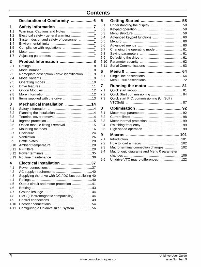
ContentsDeclaration of Conformity ................... 6
1 Safety Information .................................71.1 Warnings, Cautions and Notes .............................71.2 Electrical safety - general warning ........................71.3 System design and safety of personnel ................71.4 Environmental limits ..............................................71.5 Compliance with regulations .................................71.6 Motor .....................................................................71.7 Adjusting parameters ............................................7
2 Product Information ..............................82.1 Ratings ..................................................................82.2 Model number .......................................................82.3 Nameplate description - drive identification ..........92.4 Model variants .......................................................92.5 Operating modes .................................................102.6 Drive features ......................................................112.7 Option Modules ...................................................122.8 More information .................................................122.9 Items supplied with the drive ...............................13
3 Mechanical Installation .......................143.1 Safety information ...............................................143.2 Planning the installation ......................................143.3 Terminal cover removal .......................................143.4 Ingress protection ................................................153.5 Option module fitting / removal ...........................153.6 Mounting methods ...............................................163.7 Enclosure ............................................................243.8 Ventilation ...........................................................263.9 Baffle plates ........................................................283.10 Ambient temperature ...........................................283.11 RFI filters .............................................................293.12 Power terminals ..................................................353.13 Routine maintenance ..........................................36
4 Electrical Installation ...........................374.1 Power connections ..............................................374.2 AC supply requirements ......................................404.3 Supplying the drive with DC / DC bus paralleling 404.4 Ratings ................................................................404.5 Output circuit and motor protection .....................414.6 Braking ................................................................434.7 Ground leakage ...................................................444.8 EMC (Electromagnetic compatibility) ..................444.9 Control connections ............................................494.10 Encoder connections ...........................................544.11 Configuring a Unidrive size 5 system ..................56
5 Getting Started .................................... 585.1 Understanding the display .................................. 585.2 Keypad operation ............................................... 585.3 Menu structure ................................................... 595.4 Advanced keypad functions ............................... 605.5 Menu 0 ............................................................... 605.6 Advanced menus ............................................... 605.7 Changing the operating mode ............................ 615.8 Saving parameters ............................................. 615.9 Defaulting the drive ............................................ 615.10 Parameter security ............................................. 625.11 Serial Communications ...................................... 63
6 Menu 0 ................................................. 646.1 Single line descriptions ...................................... 646.2 Menu 0 full descriptions ..................................... 72
7 Running the motor .............................. 817.1 Quick start set-up ............................................... 817.2 Quick Start commissioning ................................. 847.3 Quick start P.C. commissioning (UniSoft /
VTCSoft) ............................................................ 87
8 Optimisation ........................................ 928.1 Motor map parameters ....................................... 928.2 Current limits ...................................................... 988.3 Motor thermal protection .................................... 998.4 Switching frequency ........................................... 998.5 High speed operation ......................................... 99
9 Macros ............................................... 1019.1 Introduction ...................................................... 1019.2 How to load a macro ........................................ 1029.3 Macro terminal connection changes ................ 1029.4 Macro logic diagrams and Menu 0 parameter
changes ............................................................ 1069.5 Unidrive VTC macro differences ...................... 122
Unidrive User Guide 5Issue Number: 9 www.controltechniques.com
10 Advanced Parameters ......................12310.1 Menu 1: Speed references and limits ...............12410.2 Menu 2: Ramps (accel. / decel.) .......................12810.3 Menu 3: Speed feedback / frequency slaving ...13110.4 Menu 4: Current control ....................................13510.5 Menu 5: Machine control ...................................13910.6 Menu 6: Sequencing logic .................................14310.7 Menu 7: Analog I/O ...........................................14510.8 Menu 8: Digital I/O ............................................14810.9 Menu 9: Programmable logic ............................15210.10 Menu 10: Status flags / trip log .........................15510.11 Menu 11: Menu 0 customisation / drive specific
ratings ...............................................................15610.12 Menu 12: Programmable thresholds .................15710.13 Menu 13: Digital lock / orientation .....................16010.14 Menu 14: Programmable PID function ..............16610.15 Menu 15: Regen ...............................................16910.16 Menu 16 Small option module set-up ...............17110.17 Menu 17: Large option module set-up ..............17910.18 Menu 18: Application menu 1 ...........................17910.19 Menu 19: Application menu 2 ...........................18010.20 Menu 20: Large option module .........................18010.21 Unidrive VTC parameter range and default
differences ........................................................18110.22 Advanced Features ...........................................182
11 Technical Data ...................................19011.1 Drive ..................................................................19011.2 Optional RFI filters ............................................197
12 Diagnostics ........................................19812.1 Trip indications ..................................................19812.2 Alarm indications ...............................................20412.3 Status indications ..............................................20412.4 Displaying the trip history ..................................204
13 UL Listing Information ......................20513.1 AC supply specification .....................................20513.2 Maximum continuous output current .................20513.3 Safety label .......................................................205
Index ...................................................206

6 Unidrive User Guidewww.controltechniques.com Issue Number: 9
Declaration of ConformityControl Techniques LtdThe GroNewtownPowysUKSY16 3BE
The AC variable speed drive products listed above, including the VTC, LFT (all sizes) and REGEN (UNI3401 to UNI4405 only) variants, have been designed and manufactured in accordance with the following European harmonised, national and international standards:
1 Conducted emission sizes 1 to 3, not size 4 or 5. See the relevant EMC Data Sheet.
These products comply with the Low Voltage Directive 73/23/EEC, the Electromagnetic Compatibility (EMC) Directive 89/336/EEC and the CE Marking Directive 93/68/EEC.
W. DruryExecutive Vice President, TechnologyNewtown
Date: 26 September 2001
These electronic drive products are intended to be used with appropriate motors, controllers, electrical protection components and other equipment to form complete end products or systems. Compliance with safety and EMC regulations depends upon installing and configuring drives correctly, including using the specified input filters. The drives must be installed only by professional assemblers who are familiar with requirements for safety and EMC. The assembler is responsible for ensuring that the end product or system complies with all the relevant laws in the country where it is to be used. A Unidrive EMC Data Sheet is also available giving detailed EMC information.
UNI1201 UNI1202 UNI1203 UNI1204 UNI1205
UNI2201 UNI2202 UNI2203
UNI3201 UNI3202 UNI3203 UNI3204
UNI1401 UNI1402 UNI1403 UNI1404 UNI1405
UNI2401 UNI2402 UNI2403
UNI3401 UNI3402 UNI3403 UNI3404 UNI3405
UNI4401 UNI4402 UNI4403 UNI4404 UNI4405
UNI5401
EN 60249 Base materials for printed circuits
IEC326-1 Printed boards: general information for the specification writer
IEC326-5 Printed boards: specification for single- and double-sided printed boards with plated-through holes
IEC326-6 Printed boards: specification for multilayer printed boards
IEC664-1 Insulation co-ordination for equipment within low-voltage systems: principles, requirements and tests
EN 60529 Degrees of protection provided by enclosures (IP code)
UL94 Flammability rating of plastic materials
UL508C Standard for power conversion equipment
EN 50081-11 Generic emission standard for the residential, commercial and light industrial environment
EN 50081-2 Generic emission standard for the industrial environment
EN 50082-2 Generic immunity standard for the industrial environment
EN 61800-3Adjustable speed electrical power drive systems - Part 3: EMC product standard including specific test methods

Safety Information
Product Information
Mechanical Installation
Electrical Installation
Getting Started Menu 0
Running the motor Optimisation Macros
Advanced Parameters
Technical Data Diagnostics
UL Listing Information
Unidrive User Guide 7Issue Number: 9 www.controltechniques.com
1 Safety Information1.1 Warnings, Cautions and Notes
A Note contains information which helps to ensure correct operation of the product.
1.2 Electrical safety - general warningThe voltages used in the drive can cause severe electrical shock and/or burns, and could be lethal. Extreme care is necessary at all times when working with or adjacent to the drive.
Specific warnings are given at the relevant places in this User Guide.
1.3 System design and safety of personnel
The drive is intended as a component for professional incorporation into complete equipment or a system. If installed incorrectly, the drive may present a safety hazard. The drive uses high voltage and currents, carries a high level of stored electrical energy, and is used to control equipment which can cause injury.
Close attention is required to the electrical installation and the system design to avoid hazards, either in normal operation or in the event of equipment malfunction. System design, installation, commissioning and maintenance must be carried out by personnel who have the necessary training and experience. They must read this safety information and this User Guide carefully.
The STOP function of the drive does not remove dangerous voltages from the output of the drive or from any external option unit.
Careful consideration must be given to the functions of the drive which might result in a hazard, either through their intended functions or through incorrect operation due to a fault.
In any application where a malfunction of the drive could lead to damage, loss or injury, a risk analysis must be carried out, and where necessary, further measures taken to reduce the risk.
The STOP and START controls or electrical inputs of the drive must not be relied upon to ensure safety of personnel. If a safety hazard could exist from unexpected starting of the drive, an interlock that electrically isolates the drive from the AC supply must be installed to prevent the motor being inadvertently started.
To ensure mechanical safety, additional safety devices such as electro-mechanical interlocks and overspeed protection devices may be required. The drive must not be used in a safety critical application without additional high integrity protection against hazards arising from a malfunction.
Under certain conditions, the drive can suddenly discontinue control of the motor. If the load on the motor could cause the motor speed to be increased (e.g. in hoists and cranes), a separate method of braking and stopping must be used (e.g. a mechanical brake).
1.4 Environmental limitsInstructions in this User Guide regarding transport, storage, installation and use of the drive must be complied with, including the specified environmental limits. Drives must not be subjected to excessive physical force.
1.5 Compliance with regulationsThe installer is responsible for complying with all relevant regulations, such as national wiring regulations, accident prevention regulations and electromagnetic compatibility (EMC) regulations. Particular attention must be given to the cross-sectional areas of conductors, the selection of fuses or other protection, and protective earth (ground) connections.
This User Guide contains instruction for achieving compliance with specific EMC standards.
Within the European Union, all machinery in which this product is used must comply with the following directives:
98/37/EC: Safety of machinery.89/336/EEC: Electromagnetic Compatibility.
1.6 MotorEnsure the motor is installed in accordance with the manufacturer’s recommendations. Ensure the motor shaft is not exposed.
Standard squirrel cage induction motors are designed for single speed operation. If it is intended to use the capability of the drive to run a motor at speeds above its designed maximum, it is strongly recommended that the manufacturer is consulted first.
Low speeds may cause the motor to overheat because the cooling fan becomes less effective. The motor should be fitted with a protection thermistor. If necessary, an electric forced vent fan should be used.
1.7 Adjusting parametersSome parameters have a profound effect on the operation of the drive. They must not be altered without careful consideration of the impact on the controlled system. Measures must be taken to prevent unwanted changes due to error or tampering.
A Warning contains information which is essential for avoiding a safety hazard.
A Caution contains information which is necessary for avoiding a risk of damage to the product or other equipment.
WARNING
CAUTION
NOTE

Safety Information
Product Information
Mechanical Installation
Electrical Installation
Getting Started Menu 0
Running the motor Optimisation Macros
Advanced Parameters
Technical Data Diagnostics
UL Listing Information
8 Unidrive User Guidewww.controltechniques.com Issue Number: 9
2 Product Information2.1 RatingsTable 2-1 200V drive ratings (200V to 240V ±10%)
Table 2-2 400V drive ratings (380V to 480V ±10%)
* The output currents are given for maximum 40°C (104°F) ambient, 1,000m altitude and 3kHz switching. Derating is required for higher switching frequencies, ambient temperatures >40°C (104°F) and high altitudes. For further information, refer to section 11.1.1 Power and current ratings on page 190.
** Multiples of 300A output current with 120% overload or multiples of 240A with 150% overload
NA Unidrive size 5 consists of a control module with one or more power modules connected in parallel.
i.e. UNI5401 = 1 x control module and 1 x power moduleUNI5402 = 1 x control module and 2 x power modules etc.
2.2 Model numberThe way in which the model numbers for the Unidrive range are formed is illustrated below.
Model
Nominal rating
Output current*
(A)
Typical Input
current (A)kW hp
1201 0.37 0.5 2.1 2.4
1202 0.55 0.75 2.8 3.5
1203 0.75 1 3.8 4.6
1204 1.1 1.5 5.6 6.5
1205 2.2 3 9.5 8.6
2201 3 4 12 10.8
2202 4 5 16 14.3
2203 5.5 10 25 19.8
3201 7.5 15 34 26
3202 11 20 46 39
3203 15 25 60 53
3204 22 30 74 78
Model
Nominal ratingOutput
current*(A)
Typical Input
current(A)
@380V @460V
kW hp
1401 0.75 1 2.1 3.0
1402 1.1 1.5 2.8 4.3
1403 1.5 2 3.8 5.8
1404 2.2 3 5.6 8.2
1405 4 5 9.5 10.0
2401 5.5 7.5 12 13.0
2402 7.5 10 16 17.0
2403 11 15 25 21.0
3401 15 25 34 27
3402 18.5 30 40 32
3403 22 30 46 40
3404 30 40 60 52
3405 37 50 70 66
4401 45 75 96 76
4402 55 100 124 91
4403 75 125 156 123
4404 90 150 180 145
4405 110 150 202 181
5401 160 200 300** 280
5402 320 400 600** 560
5403 480 600 900** 840
5404 640 800 1200** 1120
5405 800 1000 1500** 1400
5406 960 1200 1800** 1680
5407 1120 1400 2100** 1960
5408 1280 1600 2400** 2240
5
NOTE
UNI 1 2 05 LFT LV
Model:UNI - Unidrive
Voltagerating:2 - 200V4 - 400V
Model variant: - Standard variantLFT - LFT variantVTC - VTC variantREGEN - Regen variantSee section 2.4
for more detailsModel variants
Model size:1 - Size 12 - Size 23 - Size 34 - Size 45 - Size 5
Power rating:Depends on model size.See section 2.1 Ratings
Voltage rating:
LV - Low voltage (200V)
- Medium voltage (400V)

Safety Information
Product Information
Mechanical Installation
Electrical Installation
Getting Started Menu 0
Running the motor Optimisation Macros
Advanced Parameters
Technical Data Diagnostics
UL Listing Information
Unidrive User Guide 9Issue Number: 9 www.controltechniques.com
2.3 Nameplate description - drive identification
The drive label is found on the top surface of the control pod (right angles to the display) on Unidrive sizes 1 to 3 and size 5 control module, and on the side of the Unidrive size 4 and size 5 power module.
Figure 2-1 Typical drive rating labels
2.4 Model variants2.4.1 Unidrive standard industrial (STD)...for constant torque loads (All frame sizes)
Operating modes:
Open LoopClosed Loop vectorServoRegen
Overload:
Open loop 150% for 60sClosed loop vector 175% for 60s (sizes 1 to 4), 150%* for 60s (size 5)Servo 175% for 4s (sizes 1 to 4), 150%* for 4s (size 5)Regen 150% for 60s
* Multiples of 300A output current with 120% overload or multiples of 240A with 150% overload
Figure 2-2 Constant torque load
Model
Drive type (STD,LV, VTC, LFT) Power rating
Customer and date code
Approvals
Driveratings
UNI3401 VTC 15kW STDJ41
IT IS ESSENTIAL TO READTHE MANUAL BEFORE
CONNECTING THE DRIVE.
VOLTAGE 50/60 Hz 3PhINPUT OUTPUT
380/480V 380/480V
CURRENT (A) 27A 34.0A
OVERLOAD: 40.8A FOR 60 SECS
SOFTWARE VERSION: 03.02.11
RIND.CONT..EQ.
MADE IN THE U.K.
UNIDRIVE SIZE 5CONTROL MODULE HW2
IT IS ESSENTIAL TO READTHE MANUAL BEFORE
CONNECTING THE DRIVE.
R
IND.CONT..EQ.
MADE IN THE U.K.
TO BE USED IN CONJUNCTIONWITH UNIDRIVE SIZE 5 HW2
POWER MODULES (S)
SOFTWARE VERSION: 03.02.11
3000005001
STDL01
Approvals
Customer anddate code
ModelHardware revision
CE approval Europe
C Tick approval Australia
UL / cUL approvalUSA & CanadaR
UNI5401 POWER MODULE HW2 110V FAN FITTED STDL01
IT IS ESSENTIAL TO READTHE MANUAL BEFORE
CONNECTING THE DRIVE.
VOLTAGE 50/60 Hz 3PhINPUT OUTPUT
380/480V 380/480V
CURRENT (A)
220.0A 240.0AOVERLOAD: 150 FOR 60 SECS
OVERLOAD: 120 FOR 60 SECS 280.0A 300.0A
R
IND.CONT..EQ.
HEATSINK FAN110V/120V 50/60HZ
MADE IN THE U.K.
Approvals
Customer anddate code
Model
Driveratings
Dual current rating
Heatsink fanratings
Unidrive size 1 to 4 rating label
Unidrive size 5 control module rating label
Unidrive size 5 power module rating label
Key to Approvals
100
80
60
40
20
050 100
Percent kW and torque
Percent speed
Torque
kW

Safety Information
Product Information
Mechanical Installation
Electrical Installation
Getting Started Menu 0
Running the motor Optimisation Macros
Advanced Parameters
Technical Data Diagnostics
UL Listing Information
10 Unidrive User Guidewww.controltechniques.com Issue Number: 9
2.4.2 Unidrive LFT ...for lift applications
Overloads and operating modes as Unidrive standard industrial, in addition:
low acoustic noise9kHz default switching frequency S4/S5 duty cycle only
Figure 2-3 Standard S4/S5 duty cycle (Unidrive LFT)
2.4.3 Unidrive VTC...for quadratic load (variable torque) applications (fans and pumps)
Open loop fixed boost mode only
120% overload for 60sFigure 2-4 Variable torque mode
2.4.4 Unidrive REGENAll sizes of Unidrive can be used in regen mode. However, Unidrive sizes 3 and 4 require an internal modification before being used in a regen system.
This modification is already completed if the drive has been ordered as a Unidrive REGEN.
2.5 Operating modesAll variants of Unidrive (except VTC) are designed to operate in any of the following modes:
1. Open loop modeV/f mode (V/ Hz) Open loop vector
2. Closed loop vector3. Servo4. Regen
Unidrive VTC can only operate in open loop quadratic V/f mode.
2.5.1 Open Loop mode (OL)For use with standard AC induction motors.
The drive applies power to the motor at frequencies varied by the user. The motor speed is a result of the output frequency of the drive and slip due to the mechanical load. The drive can improve the performance of the motor by applying slip compensation. The performance at low speed depends on whether V/f mode or open loop vector mode is selected.
V/f modeThe voltage applied to the motor is directly proportional to the frequency except at low speed where a voltage boost is provided which is set by the user. This mode should used for multi-motor applications.
Typically 100% torque at 4Hz.
Open loop vector mode The voltage applied to the motor is directly proportional to the frequency except at low speed where the drive uses motor parameters to apply the correct voltage to keep the flux constant under varying load conditions.
Typically 100% torque at 1Hz.
2.5.2 Closed loop vector mode (VT)For use with induction motors with a speed feedback device fitted.
The drive directly controls the speed of the motor using the feedback device to ensure the rotor speed is exactly as demanded. Motor flux is accurately controlled at all times to provide full torque all the way down to zero speed.
Typically 175% torque at 0rpm.
2.5.3 Servo (SV)For use with permanent magnet brushless motors with a speed and position feedback device fitted.
The drive directly controls the speed of the motor using the feedback device to ensure the rotor speed is exactly as demanded. Flux control is not required because the motor is self excited by the permanent magnets which form part of the rotor.
Absolute position information is required from the feedback device to ensure the output voltage is accurately matched to the back EMF of the motor.
Typically 175% torque at 0rpm
2.5.4 RegenFor use as a regenerative front end for four quadrant operation.
Regen operation allows bi-directional power flow to and from the AC supply. This provides far greater efficiency levels in applications which would otherwise dissipate large amounts of energy in the form of heat in a braking resistor.
The harmonic content of the input current is negligible due to the sinusoidal nature of the waveform when compared to a conventional bridge rectifier or thyristor front end.
See the Regen Installation Guide for more information on this operating mode.
2.5.5 Key to operating mode abbreviationsAbbreviations are throughout this User Guide to define the operating mode for which the information applies as follows:
OL> Open loopCL> Closed loop (which incorporates closed loop vector and
servo mode) VT> Closed loop vector modeSV> Servo
Frequency / speed
Current
20 60
50Hz1500 RPM
0
100%
0
0
150%
2
100
80
60
40
20
050 100
Percent kW and torque
Percent speed
Torque
kW
Safety Information
Product Information
Mechanical Installation
Electrical Installation
Getting Started Menu 0
Running the motor Optimisation Macros
Advanced Parameters
Technical Data Diagnostics
UL Listing Information
Unidrive User Guide 11Issue Number: 9 www.controltechniques.com
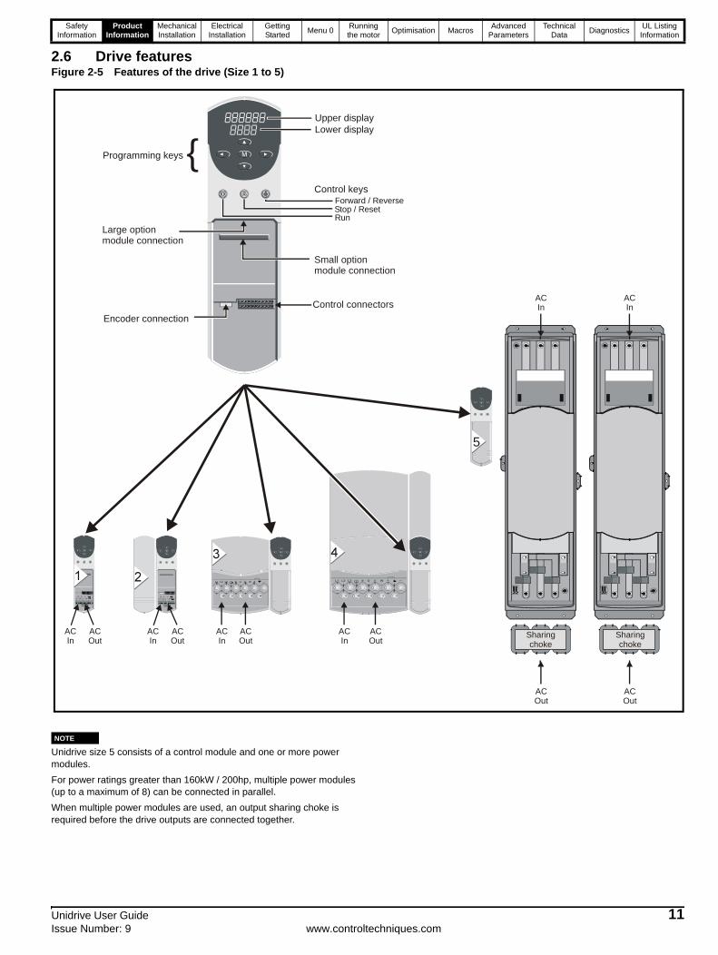
2.6 Drive featuresFigure 2-5 Features of the drive (Size 1 to 5)
NUnidrive size 5 consists of a control module and one or more power modules.
For power ratings greater than 160kW / 200hp, multiple power modules (up to a maximum of 8) can be connected in parallel.
When multiple power modules are used, an output sharing choke is required before the drive outputs are connected together.
Programming keys
Control keys
RunStop / ResetForward / Reverse
Upper displayLower display
Encoder connection
{
Large option module connection
Control connectors
Small option module connection
5
ACIn
ACOut
ACIn
ACOut
ACIn
ACOut
ACOut
ACIn
ACIn
ACOut
ACOut
ACIn
Sharingchoke
Sharingchoke
NOTE
Safety Information
Product Information
Mechanical Installation
Electrical Installation
Getting Started Menu 0
Running the motor Optimisation Macros
Advanced Parameters
Technical Data Diagnostics
UL Listing Information
12 Unidrive User Guidewww.controltechniques.com Issue Number: 9
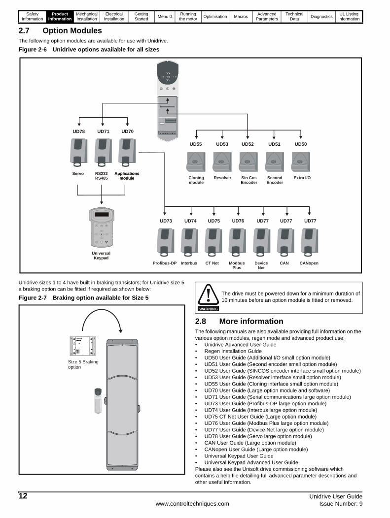
2.7 Option ModulesThe following option modules are available for use with Unidrive.
Figure 2-6 Unidrive options available for all sizes
Unidrive sizes 1 to 4 have built in braking transistors; for Unidrive size 5 a braking option can be fitted if required as shown below:
Figure 2-7 Braking option available for Size 5
2.8 More informationThe following manuals are also available providing full information on the various option modules, regen mode and advanced product use:• Unidrive Advanced User Guide• Regen Installation Guide• UD50 User Guide (Additional I/O small option module)• UD51 User Guide (Second encoder small option module)• UD52 User Guide (SINCOS encoder interface small option module)• UD53 User Guide (Resolver interface small option module)• UD55 User Guide (Cloning interface small option module)• UD70 User Guide (Large option module and software)• UD71 User Guide (Serial communications large option module)• UD73 User Guide (Profibus-DP large option module)• UD74 User Guide (Interbus large option module)• UD75 CT Net User Guide (Large option module)• UD76 User Guide (Modbus Plus large option module)• UD77 User Guide (Device Net large option module)• UD78 User Guide (Servo large option module)• CAN User Guide (Large option module)• CANopen User Guide (Large option module)• Universal Keypad User Guide• Universal Keypad Advanced User GuidePlease also see the Unisoft drive commissioning software which contains a help file detailing full advanced parameter descriptions and other useful information.
UD78 UD71 UD70
UD55 UD53 UD52 UD51 UD50
UD73 UD74 UD75 UD76
Servo RS232RS485
Applicationsmodule
Applicationsmodule Cloning
moduleResolver Sin Cos
EncoderSecondEncoder
Extra I/O
Profibus-DP Interbus CT Net ModbusPlus
UD77 UD77 UD77
DeviceNet
CAN CANopen
9901 11destination addr
F1 F2 F3
M
Universal Keypad
Size 5 Braking option
The drive must be powered down for a minimum duration of 10 minutes before an option module is fitted or removed.
WARNING
Safety Information
Product Information
Mechanical Installation
Electrical Installation
Getting Started Menu 0
Running the motor Optimisation Macros
Advanced Parameters
Technical Data Diagnostics
UL Listing Information
Unidrive User Guide 13Issue Number: 9 www.controltechniques.com
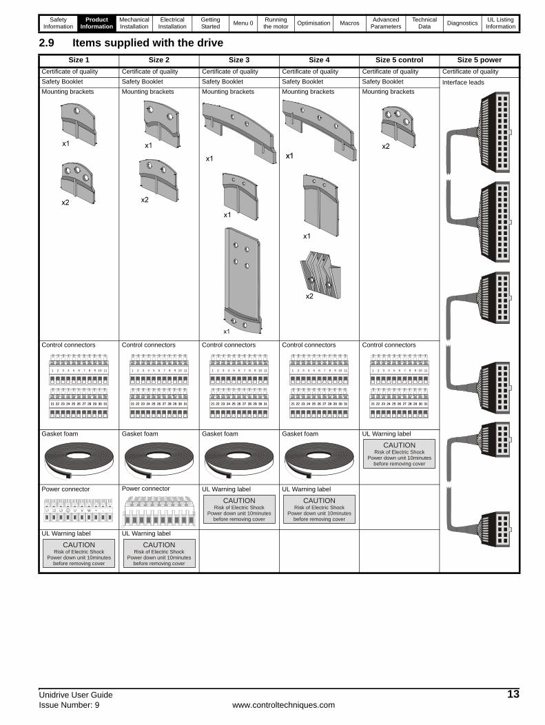
2.9 Items supplied with the driveSize 1 Size 2 Size 3 Size 4 Size 5 control Size 5 power
Certificate of quality Certificate of quality Certificate of quality Certificate of quality Certificate of quality Certificate of quality
Safety Booklet Safety Booklet Safety Booklet Safety Booklet Safety Booklet Interface leads
Mounting brackets Mounting brackets Mounting brackets Mounting brackets Mounting brackets
Control connectors Control connectors Control connectors Control connectors Control connectors
Gasket foam Gasket foam Gasket foam Gasket foam UL Warning label
Power connector Power connector UL Warning label UL Warning label
UL Warning label UL Warning label
1 2 3 4 5 6 7 8 9 10 11
21 22 23 24 25 26 27 28 29 30 3121 22 23 24 25 26 27 28 29 30 31
1 2 3 4 5 6 7 8 9 10 11
21 22 23 24 25 26 27 28 29 30 3121 22 23 24 25 26 27 28 29 30 31
1 2 3 4 5 6 7 8 9 10 11
21 22 23 24 25 26 27 28 29 30 3121 22 23 24 25 26 27 28 29 30 31
1 2 3 4 5 6 7 8 9 10 11
21 22 23 24 25 26 27 28 29 30 3121 22 23 24 25 26 27 28 29 30 31
1 2 3 4 5 6 7 8 9 10 11
21 22 23 24 25 26 27 28 29 30 3121 22 23 24 25 26 27 28 29 30 31
CAUTIONRisk of Electric Shock
Power down unit 10minutesbefore removing cover
L1 L2 L3 U V W + . -
CAUTIONRisk of Electric Shock
Power down unit 10minutesbefore removing cover
CAUTIONRisk of Electric Shock
Power down unit 10minutesbefore removing cover
CAUTIONRisk of Electric Shock
Power down unit 10minutesbefore removing cover
CAUTIONRisk of Electric Shock
Power down unit 10minutesbefore removing cover