EMERGENCY VOICE COMMUNICATION SYSTEMS (EVC) · to look at the communication issues involved within...
20
EMERGENCY VOICE COMMUNICATION SYSTEMS (EVC)
Transcript of EMERGENCY VOICE COMMUNICATION SYSTEMS (EVC) · to look at the communication issues involved within...

E M E R G E N C Y V O I C EC O M M U N I C A T I O N
S Y S T E M S ( E V C )

F or over twenty years we at Baldwin Boxall have been at the forefront of the communicationsindustry and are proudly recognised as being Europe’s leading independent manufacturer ofVoice Alarm/Voice Evacuation (VA/VE), Emergency Voice Communication Systems (EVC), and
Public Address (PA) Equipment. Over the past few years we have been asked by major organisationsto look at the communication issues involved within BS5588 and BS5839 part 9.
The result is Baldwin Boxall’s well established range of Emergency Voice Communication Systems;VIGIL AssureCare,VIGIL CommuniCare,VIGIL CommuniCare Advance and VIGIL FireCare:
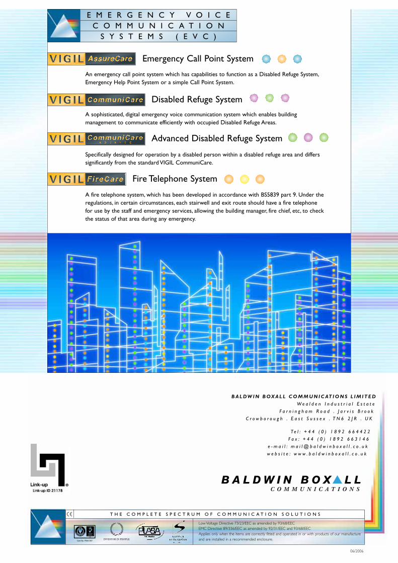
An emergency call point system which has the capability to function as a DisabledRefuge System, Emergency Help Point System or a simple Call Point System.
A sophisticated, digital emergency voice communication system which enables buildingmanagement to communicate efficiently with occupied Disabled Refuge Areas.
Specifically designed for operation by a disabled person within a disabled refuge areaand differs significantly from the standard VIGIL CommuniCare.
A fire telephone system, which has been developed in accordance with BS5839 part 9.Under the regulations, in certain circumstances, each stairwell and exit route shouldhave a fire telephone for use by the staff and emergency services, allowing the buildingmanager, fire chief, etc, to check the status of that area during any emergency.
All four systems are simple to install, operate and work independently (apart from AssureCare andCommuniCare Advance) to any other emergency communication system within a building.They arewired in a ring circuit configuration and are self-learning, thus enabling an auto-commissioning feature, butimportantly saves up to 75% on cabling costs compared to typical star circuit systems. All four utilise a 4-wire plus screen ring circuit to allow continued operation in the event of a cable break; that meansshould part of a circuit be broken or damaged all the remote units continue to work.
The systems have two main components; the Master Control Panel and the Remote Units.The MasterControl Panel is typically wall mounted within a central Control Room.The Remote Units are wallmounted in areas such as refuge areas, stairwells, fallback positions, corridors and other ‘gathering’ pointsat a height easily reached by occupants (please refer to BS5839 part 9 explained, on page 16, forrecommended mounting heights). Master panels can be configured as a remote Slave panel(s) on thering circuit, thus allowing control of local areas.
1
Page 2
Page 4
Page 6
Page 8
E M E R G E N C Y V O I C EC O M M U N I C A T I O N
S Y S T E M S ( E V C )

Monitored Cal l Point System that compl ies with :
BS 5839 (Par t 9) leg is lat ion.
Sa fe and ef f ic ient emergency communicat ion with in any structure .
The key feature of an emergency Call Point system is that it must work when needed. Finding it hasbeen vandalised or has a fault as an emergency unfolds is a far from an ideal state.Thus themonitoring of function and versatility are standard within an AssureCare system.That is why ourVIGIL AssureCare system is such a market leader – it was designed with functionality andpracticality equally in mind.
Master Control Panel:
� Up to 128 way. Available in 8-32,16-64 and 80-128 way options.
� Wall mountable – optional flush or rack mounting (8-32 way and 16-64 way only).
� Lockable glazed door.
� Half duplex speech (via remote unit).
� Activated via Fire Detection System (see ‘Fire Panel Interface’ on page 11).
� Fully monitored – faults reported at the Master Control Panel.
� Battery backed – 24 hours quiescent with three hours use, 230V AC with built-in battery charger.
� Volt free contact – operated when in fault, set during installation.
� Indicators for : in use/occupied, call, fault, power, charger and speech volume.
� Labels for all the control panel buttons can be inserted behind a membrane.
� ‘Listening’ facility.
� Slave Control Panels available.
� Fully BS5839 part 9 compliant, when installed according to the standard.
� Distinguishing ‘blue’ name panel.
� Weight (including battery) 8-32 way 21kg, 16-64 way 26kg, 16-128 way 37kg.
PRODUCT CODES
Master control panels: BVCP08M~8 way, BVCP16M~16 way, BVCP32M~32 way.BVCP16~16 way, BVCP32~32 way, BVCP48~48 way, BVCP64~64 way, BVCP80~80 way, BVCP96~96way, BVCP112~112 way, BVCP128~128 way.
Remote Units: BVCRCAL~standard red unit, BVCRCALS~standard stainless steel unit.
Repeater Unit: BVCREPE.
Bezels: BVCRFB2~8-32 way master control panel bezel,BVCRFB1~16-64 way master control panel bezel.BVCRMRED~Bezel for BVCRCAL standard red remote unit,BVCRMSS~Bezel for BVCRCALS standard stainless steel remote unit.
Break Glass Unit: BVCRBG.
Emergency Call Point System
2
Typically20-30
remotesper loop
Typically 20-30
remotesper loop
Typically 20-30 remotes
per loop
Typically 20-30 remotes
per loop
BVCP128~128 way
BVCP64~64 way
BVCP32M~32 way
Any number of mastercontrol panels - with a
maximum of 128 remoteunits - can be linked in
one system.A minimum of 2 remote
units must be used.
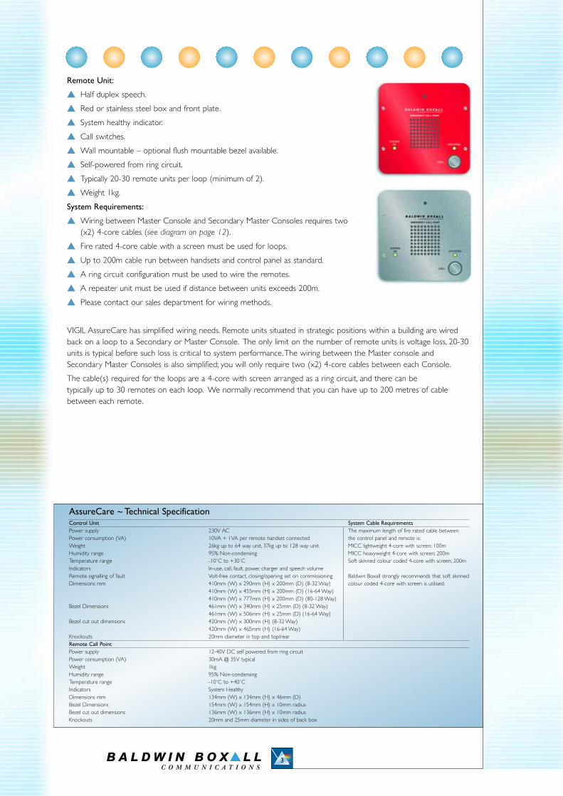
Remote Unit:
� Half duplex speech.
� Red or stainless steel box and front plate.
� System healthy indicator.
� Call switches.
� Wall mountable – optional flush mountable bezel available.
� Self-powered from ring circuit.
� Typically 20-30 remote units per loop (minimum of 2).
� Weight 1kg.
System Requirements:
� Wiring between Master Console and Secondary Master Consoles requires two (x2) 4-core cables (see diagram on page 12).
� Fire rated 4-core cable with a screen must be used for loops.
� Up to 200m cable run between handsets and control panel as standard.
� A ring circuit configuration must be used to wire the remotes.
� A repeater unit must be used if distance between units exceeds 200m.
� Please contact our sales department for wiring methods.
VIGIL AssureCare has simplified wiring needs. Remote units situated in strategic positions within a building are wiredback on a loop to a Secondary or Master Console. The only limit on the number of remote units is voltage loss, 20-30units is typical before such loss is critical to system performance.The wiring between the Master console andSecondary Master Consoles is also simplified; you will only require two (x2) 4-core cables between each Console.
The cable(s) required for the loops are a 4-core with screen arranged as a ring circuit, and there can be typically up to 30 remotes on each loop. We normally recommend that you can have up to 200 metres of cablebetween each remote.
3
AssureCare ~ Technical SpecificationControl Unit System Cable RequirementsPower supply 230V AC The maximum length of fire rated cable betweenPower consumption (VA) 10VA + 1VA per remote handset connected the control panel and remote is:Weight 26kg up to 64 way unit, 37kg up to 128 way unit. MICC lightweight 4-core with screen; 100mHumidity range 95% Non-condensing MICC heavyweight 4-core with screen; 200mTemperature range -10˚C to +30˚C Soft skinned colour coded 4-core with screen; 200mIndicators In-use, call, fault, power, charger and speech volumeRemote signalling of fault Volt-free contact, closing/opening set on commissioning Baldwin Boxall strongly recommends that soft skinnedDimensions mm 410mm (W) x 290mm (H) x 200mm (D) (8-32 Way) colour coded 4-core with screen is utilised.
410mm (W) x 455mm (H) x 200mm (D) (16-64 Way)410mm (W) x 777mm (H) x 200mm (D) (80-128 Way)
Bezel Dimensions 461mm (W) x 340mm (H) x 25mm (D) (8-32 Way)461mm (W) x 506mm (H) x 25mm (D) (16-64 Way)
Bezel cut out dimensions 420mm (W) x 300mm (H) (8-32 Way)420mm (W) x 465mm (H) (16-64 Way)
Knockouts 20mm diameter in top and top/rearRemote Call Point Power supply 12-40V DC self powered from ring circuitPower consumption (VA) 30mA @ 35V typicalWeight 1kg Humidity range 95% Non-condensingTemperature range -10˚C to +40˚CIndicators System Healthy Dimensions mm 134mm (W) x 134mm (H) x 46mm (D)Bezel Dimensions 154mm (W) x 154mm (H) x 10mm radiusBezel cut out dimensions 136mm (W) x 136mm (H) x 10mm radiusKnockouts 20mm and 25mm diameter in sides of back box

The safe and efficient emergency evacuation of any structure, be it a large shopping centre, a cinema,stadium, school or college, etc, has always been a challenge to the building management andemergency services. Chief amongst the issues has always been the safety of the disabled users whoare unable to self-evacuate. Manually handling disabled patrons, especially down stairwells, is at bestproblematic.With the introduction of the Disability Discrimination Act of October 2004, this issuebecomes not only topical, but one that is also now a key part of Health & Safety for all buildings andtheir owner/operators.
Master Control Panel:
� Up to 64 way. Available in 8-32 and 16-64 way options.
� Wall mountable – optional flush or rack mounting (8-32 way and 16-64 way only).
� Lockable glazed door.
� Half duplex speech.
� Fully monitored – faults reported at the Master Control Panel.
� Battery backed – 24 hours quiescent with three hours use, 230VAC with in-built battery charger.
� Volt free contact – operated when in fault, set during installation.
� Indicators for : in use/occupied, call, fault, power, charger and speech volume.
� Labels for all the control panel buttons can be inserted behind a membrane.
� ‘Listening’ facility.
� Slave Control Panel available.
� Fully BS5588 Part 8 and BS5839 part 9 compliant, when installed according to both standards.
� Distinguishing ‘green’ name panel.
� Weight (including battery) 8-32 way 21kg, 16-64 way 26kg.
PRODUCT CODES
Master Control Panels: BVCR08M~8 way, BVCR16M~16 way, BVCR32M~32 way.BVCR16~16 way, BVCR32~32 way, BVCR48~48 way, BVCR64~64 way.
Remote Units: BVCREFU~standard red unit, BVCREFUS~standard stainless steel unit.
Repeater Unit: BVCREPE.
Bezels: BVCRFB2~8-32 way master control panel bezel,BVCRFBI~16-64 way master control panel bezel.BVCRMRED~Bezel for BVCREFU standard red remote unit,BVCRMSS~Bezel for BVCREFUS standard stainless steel remote unit.
Disabled Refuge System
4
Disabled Refuge System that complies with:
BS 5839 (Part 9) and assists with compliance to the Disability Discrimination
Act (DDA). Safe and efficient emergency evacuation within any structure.
Up to 16remotesper loop
Up to 16remotesper loop
Up to 16remotesper loop
Up to 16remotesper loop
BVCR64~64 way
BVCR32M~32 way
Up to 2 master controlpanels - with a maximum of
64 remote units - can belinked in one system.
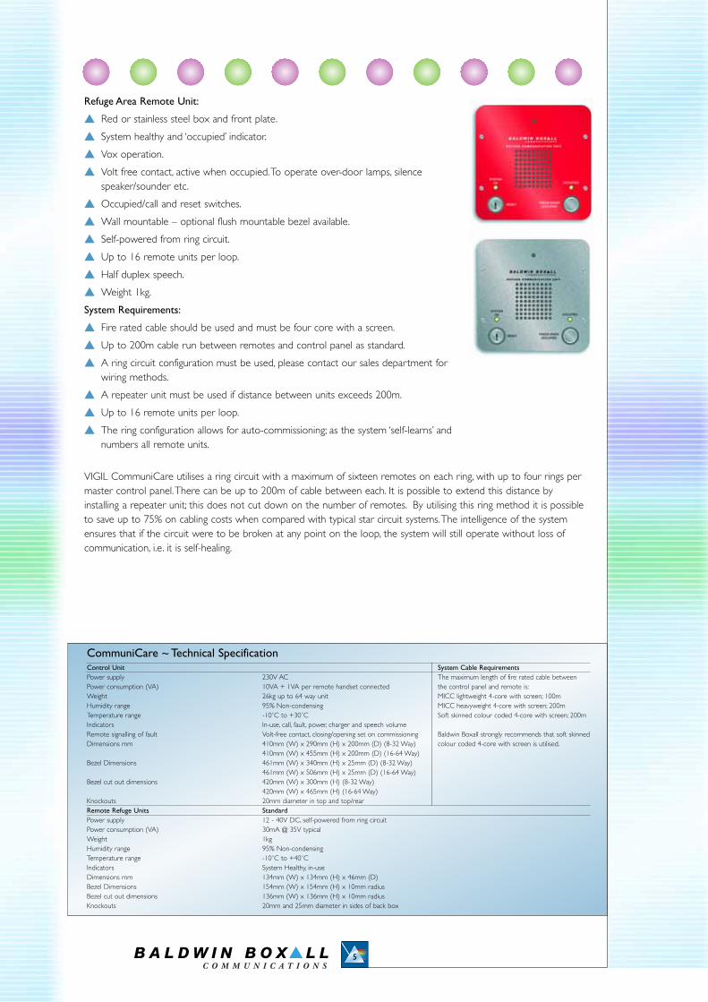
Refuge Area Remote Unit:
� Red or stainless steel box and front plate.
� System healthy and ‘occupied’ indicator.
� Vox operation.
� Volt free contact, active when occupied.To operate over-door lamps, silence speaker/sounder etc.
� Occupied/call and reset switches.
� Wall mountable – optional flush mountable bezel available.
� Self-powered from ring circuit.
� Up to 16 remote units per loop.
� Half duplex speech.
� Weight 1kg.
System Requirements:
� Fire rated cable should be used and must be four core with a screen.
� Up to 200m cable run between remotes and control panel as standard.
� A ring circuit configuration must be used, please contact our sales department for wiring methods.
� A repeater unit must be used if distance between units exceeds 200m.
� Up to 16 remote units per loop.
� The ring configuration allows for auto-commissioning; as the system ‘self-learns’ and numbers all remote units.
VIGIL CommuniCare utilises a ring circuit with a maximum of sixteen remotes on each ring, with up to four rings permaster control panel.There can be up to 200m of cable between each. It is possible to extend this distance byinstalling a repeater unit; this does not cut down on the number of remotes. By utilising this ring method it is possibleto save up to 75% on cabling costs when compared with typical star circuit systems.The intelligence of the systemensures that if the circuit were to be broken at any point on the loop, the system will still operate without loss ofcommunication, i.e. it is self-healing.
5
CommuniCare ~ Technical SpecificationControl Unit System Cable RequirementsPower supply 230V AC The maximum length of fire rated cable betweenPower consumption (VA) 10VA + 1VA per remote handset connected the control panel and remote is:Weight 26kg up to 64 way unit MICC lightweight 4-core with screen; 100mHumidity range 95% Non-condensing MICC heavyweight 4-core with screen; 200mTemperature range -10˚C to +30˚C Soft skinned colour coded 4-core with screen; 200mIndicators In-use, call, fault, power, charger and speech volumeRemote signalling of fault Volt-free contact, closing/opening set on commissioning Baldwin Boxall strongly recommends that soft skinnedDimensions mm 410mm (W) x 290mm (H) x 200mm (D) (8-32 Way) colour coded 4-core with screen is utilised.
410mm (W) x 455mm (H) x 200mm (D) (16-64 Way)Bezel Dimensions 461mm (W) x 340mm (H) x 25mm (D) (8-32 Way)
461mm (W) x 506mm (H) x 25mm (D) (16-64 Way)Bezel cut out dimensions 420mm (W) x 300mm (H) (8-32 Way)
420mm (W) x 465mm (H) (16-64 Way)Knockouts 20mm diameter in top and top/rearRemote Refuge Units StandardPower supply 12 - 40V DC, self-powered from ring circuitPower consumption (VA) 30mA @ 35V typicalWeight 1kgHumidity range 95% Non-condensingTemperature range -10˚C to +40˚CIndicators System Healthy, in-useDimensions mm 134mm (W) x 134mm (H) x 46mm (D)Bezel Dimensions 154mm (W) x 154mm (H) x 10mm radiusBezel cut out dimensions 136mm (W) x 136mm (H) x 10mm radiusKnockouts 20mm and 25mm diameter in sides of back box
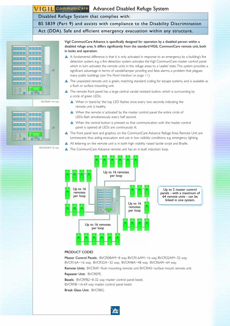
Vigil CommuniCare Advance is specifically designed for operation by a disabled person within adisabled refuge area. It differs significantly from the standard VIGIL CommuniCare remote unit, bothin looks and operation:
� A fundamental difference is that it is only activated in response to an emergency, by a building’s fire detection system, e.g. a fire detection system activates the Vigil CommuniCare master control panel which in turn activates the remote units in the refuge areas to a ‘usable’ state.This system provides asignificant advantage in terms of vandal/tamper proofing and false alarms, a problem that plagues many public buildings (see ‘Fire Panel Interface’ on page 11).
� The unassisted remote unit is green, matching standard coding for escape systems, and is available asa flush or surface mounting unit.
� The remote front panel has a large central vandal resistant button, which is surrounding by a circle of green LEDs:
� When in ‘stand-by’ the top LED flashes once every two seconds, indicating the remote unit is healthy.
� When the remote is ‘activated’ by the master control panel the entire circle of LEDs flash simultaneously every half second.
� When the central button is pressed so that communication with the master control panel is opened all LEDs are continuously lit.
� The front panel text and graphics on the CommuniCare Advance Refuge Area Remote Unit are luminescent, thus aiding evacuation and use in low visibility conditions, e.g. emergency lighting.
� All lettering on the remote unit is in both high visibility raised tactile script and Braille.
� The CommuniCare Advance remote unit has an in-built induction loop.
PRODUCT CODES
Master Control Panels: BVCR08AM~8 way, BVCR16AM~16 way, BVCR32AM~32 way.BVCR16A~16 way, BVCR32A~32 way, BVCR48A~48 way, BVCR64A~64 way.
Remote Units: BVCRAF~flush mounting remote unit BVCRAS~surface mount remote unit.
Repeater Unit: BVCREPE.
Bezels: BVCRFB2~8-32 way master control panel bezel,BVCRFBI~16-64 way master control panel bezel.
Break Glass Unit: BVCRBG.
Advanced Disabled Refuge System
6
Disabled Refuge System that complies with:
BS 5839 (Part 9) and assists with compliance to the Disability Discrimination
Act (DDA). Safe and efficient emergency evacuation within any structure.
Up to 16remotesper loop
Up to 16remotesper loop
Up to 16 remotes per loop
Up to 16 remotes per loop
BVCR64A~64 way
BVCR32AM~32 way
Up to 2 master controlpanels - with a maximum of
64 remote units - can belinked in one system.

Master Control Panel:Features as standard VIGIL CommuniCare Master Control Panel apart from:
� Up to 64 way. Available in 8-32 and 16-64 way options.� Activated via the Fire Detection System.� Emergency override and test contact via break glass unit
(break glass unit product code: BVCRBG).Refuge Area Remote Unit:� Half duplex speech.� Green finish.� All text is tactile, in Braille and luminescent.� In-built induction loop.� System in standby/healthy, activated and ‘occupied’ indicator.� Volt free contact, active when occupied.To operate over-door lamps, silence
speaker/sounder etc.� Reset facility.� Wall mountable – flush or surface mount.� Self-powered from ring circuit.� Up to 16 remote units per loop.� Weight 1kg.System Requirements:� Fire rated cable should be used and must be four core with a screen.� Up to 200m cable run between remotes and control panel as standard.� A ring circuit configuration must be used, please contact our sales department
for wiring methods.� A repeater unit must be used if distance between units exceeds 200m.� Up to 16 remote units per loop.� The ring configuration allows for auto-commissioning; the system ‘self-learns’ and numbers all remote units.
Please note the unit is not VOX operated.
VIGIL CommuniCare Advance utilises a ring circuit with a maximum of sixteen remotes on each ring, with up to four ringsper master control panel.There can be up to 200m of cable between each. It is possible to extend this distance byinstalling a repeater unit; this does not cut down on the number of remotes. By utilising this ring method it is possible tosave up to 75% on cabling costs when compared with typical star circuit systems.The intelligence of the system ensuresthat if the circuit were to be broken at any point on the loop, the system will still operate without loss of communication,i.e. it is self-healing. Lift refuge point available, see page 11.
7
CommuniCare Advance ~ Technical SpecificationControl Unit System Cable RequirementsPower supply 230V AC The maximum length of fire rated cable betweenPower consumption (VA) 10VA + 1VA per remote handset connected the control panel and remote is:Weight 26kg up to 64 way unit, 37kg up to 128 way unit. MICC lightweight 4-core with screen; 100mHumidity range 95% Non-condensing MICC heavyweight 4-core with screen; 200mTemperature range -10˚C to +30˚C Soft skinned colour coded 4-core with screen; 200mIndicators In-use, call, fault, power, charger and speech volumeRemote signalling of fault Volts-free contact, closing/opening set on commissioning Baldwin Boxall strongly recommends that soft skinnedDimensions mm 410mm (W) x 290mm (H) x 200mm (D) (8-32 Way) colour coded 4-core with screen is utilised.
410mm (W) x 455mm (H) x 200mm (D) (16-64 Way)Bezel Dimensions 461mm (W) x 340mm (H) x 25mm (D) (8-32 Way)
461mm (W) x 506mm (H) x 25mm (D) (16-64 Way)Bezel cut out dimensions 420mm (W) x 300mm (H) (8-32 Way)
420mm (W) x 465mm (H) (16-64 Way)Knockouts 20mm diameter in top and top/rearRemote Refuge Units AdvancePower supply 12 – 40V DC, self-powered form ring circuitPower consumption (VA) 30mA @ 35V typicalWeight 1kgHumidity range 95% Non-condensingTemperature range -10˚C to +40˚CIndicators System Healthy, system activated and in-useDimensions Flush mm 178mm (W) x 440mm (H) x 3mm (D)Dimensions Surface mount mm 180mm (W) x 440mm (H) x 64mm (D)Flush mount cut out dimensions 133mm (W) x 235mm (H) x 65mm (D)Knockouts 20mm and 25mm diameter in sides of back box
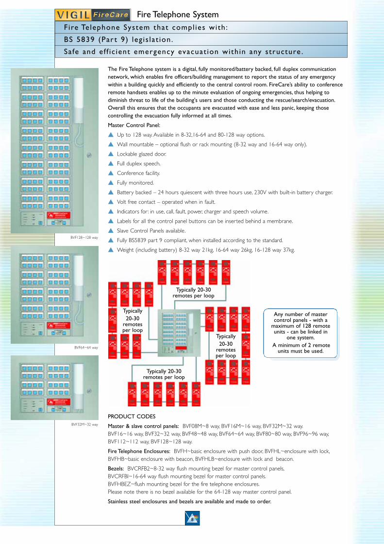
The Fire Telephone system is a digital, fully monitored/battery backed, full duplex communicationnetwork, which enables fire officers/building management to report the status of any emergencywithin a building quickly and efficiently to the central control room. FireCare’s ability to conferenceremote handsets enables up to the minute evaluation of ongoing emergencies, thus helping todiminish threat to life of the building's users and those conducting the rescue/search/evacuation.Overall this ensures that the occupants are evacuated with ease and less panic, keeping thosecontrolling the evacuation fully informed at all times.
Master Control Panel:
� Up to 128 way. Available in 8-32,16-64 and 80-128 way options.
� Wall mountable – optional flush or rack mounting (8-32 way and 16-64 way only).
� Lockable glazed door.
� Full duplex speech.
� Conference facility.
� Fully monitored.
� Battery backed – 24 hours quiescent with three hours use, 230V with built-in battery charger.
� Volt free contact – operated when in fault.
� Indicators for : in use, call, fault, power, charger and speech volume.
� Labels for all the control panel buttons can be inserted behind a membrane.
� Slave Control Panels available.
� Fully BS5839 part 9 compliant, when installed according to the standard.
� Weight (including battery) 8-32 way 21kg, 16-64 way 26kg, 16-128 way 37kg.
PRODUCT CODES
Master & slave control panels: BVF08M~8 way, BVF16M~16 way, BVF32M~32 way.BVF16~16 way, BVF32~32 way, BVF48~48 way, BVF64~64 way, BVF80~80 way, BVF96~96 way,BVF112~112 way, BVF128~128 way.
Fire Telephone Enclosures: BVFH~basic enclosure with push door, BVFHL~enclosure with lock,BVFHB~basic enclosure with beacon, BVFHLB~enclosure with lock and beacon.
Bezels: BVCRFB2~8-32 way flush mounting bezel for master control panels,BVCRFBI~16-64 way flush mounting bezel for master control panels.BVFHBEZ~flush mounting bezel for the fire telephone enclosures.Please note there is no bezel available for the 64-128 way master control panel.
Stainless steel enclosures and bezels are available and made to order.
Fire Telephone System
8
Fire Telephone System that compl ies with :
BS 5839 (Par t 9) leg is lat ion.
Sa fe and ef f ic ient emergency evacuat ion with in any structure .
Typically 20-30
remotesper loop
Typically 20-30
remotesper loop
Typically 20-30remotes per loop
Typically 20-30 remotes per loop
BVF128~128 way
BVF64~64 way
BVF32M~32 way
Any number of mastercontrol panels - with a
maximum of 128 remoteunits - can be linked in
one system.A minimum of 2 remote
units must be used.
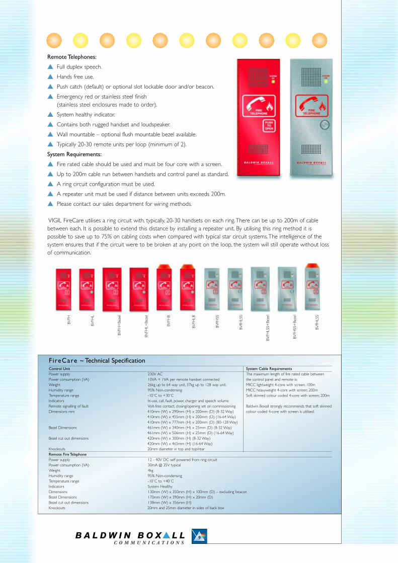
Remote Telephones:
� Full duplex speech.
� Hands free use.
� Push catch (default) or optional slot lockable door and/or beacon.
� Emergency red or stainless steel finish (stainless steel enclosures made to order).
� System healthy indicator.
� Contains both rugged handset and loudspeaker.
� Wall mountable – optional flush mountable bezel available.
� Typically 20-30 remote units per loop (minimum of 2).
System Requirements:
� Fire rated cable should be used and must be four core with a screen.
� Up to 200m cable run between handsets and control panel as standard.
� A ring circuit configuration must be used.
� A repeater unit must be used if distance between units exceeds 200m.
� Please contact our sales department for wiring methods.
VIGIL FireCare utilises a ring circuit with, typically, 20-30 handsets on each ring.There can be up to 200m of cablebetween each. It is possible to extend this distance by installing a repeater unit. By utilising this ring method it is possible to save up to 75% on cabling costs when compared with typical star circuit systems.The intelligence of thesystem ensures that if the circuit were to be broken at any point on the loop, the system will still operate without lossof communication.
9
F ireCare ~ Technical SpecificationControl Unit System Cable RequirementsPower supply 230V AC The maximum length of fire rated cable betweenPower consumption (VA) 10VA + 1VA per remote handset connected the control panel and remote is:Weight 26kg up to 64 way unit, 37kg up to 128 way unit. MICC lightweight 4-core with screen; 100mHumidity range 95% Non-condensing MICC heavyweight 4-core with screen; 200mTemperature range -10˚C to +30˚C Soft skinned colour coded 4-core with screen; 200mIndicators In-use, call, fault, power, charger and speech volumeRemote signalling of fault Volt-free contact, closing/opening set on commissioning Baldwin Boxall strongly recommends that soft skinnedDimensions mm 410mm (W) x 290mm (H) x 200mm (D) (8-32 Way) colour coded 4-core with screen is utilised.
410mm (W) x 455mm (H) x 200mm (D) (16-64 Way)410mm (W) x 777mm (H) x 200mm (D) (80-128 Way)
Bezel Dimensions 461mm (W) x 340mm (H) x 25mm (D) (8-32 Way)461mm (W) x 506mm (H) x 25mm (D) (16-64 Way)
Bezel cut out dimensions 420mm (W) x 300mm (H) (8-32 Way)420mm (W) x 465mm (H) (16-64 Way)
Knockouts 20mm diameter in top and top/rearRemote Fire Telephone Power supply 12 - 40V DC self powered from ring circuitPower consumption (VA) 30mA @ 35V typicalWeight 4kg Humidity range 95% Non-condensingTemperature range -10˚C to +40˚CIndicators System Healthy Dimensions 130mm (W) x 350mm (H) x 100mm (D) – excluding beaconBezel Dimensions 170mm (W) x 390mm (H) x 20mm (D) Bezel cut out dimensions 138mm (W) x 356mm (H)Knockouts 20mm and 25mm diameter in sides of back box
BVFH
BVFH
L
BVFH
+Be
zel
BVFH
L+Be
zel
BVFH
B
BVFH
LB
BVFH
SS
BVFH
LSS
BVFH
LSS+
Beze
l
BVFH
SS+
Beze
l
BVFH
LSS
10
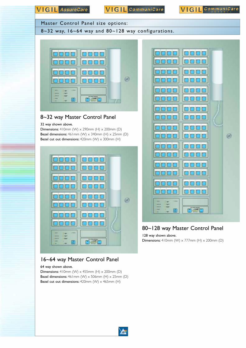
Master Control Panel s ize opt ions :
8~32 way, 16~64 way and 80~128 way conf igurat ions .
80~128 way Master Control Panel128 way shown above.Dimensions: 410mm (W) x 777mm (H) x 200mm (D)
16~64 way Master Control Panel64 way shown above.Dimensions: 410mm (W) x 455mm (H) x 200mm (D)Bezel dimensions: 461mm (W) x 506mm (H) x 25mm (D)Bezel cut out dimensions: 420mm (W) x 465mm (H)
8~32 way Master Control Panel32 way shown above.Dimensions: 410mm (W) x 290mm (H) x 200mm (D)Bezel dimensions: 461mm (W) x 340mm (H) x 25mm (D)Bezel cut out dimensions: 420mm (W) x 300mm (H)
11
O P T I O N S A V A I L A B L E
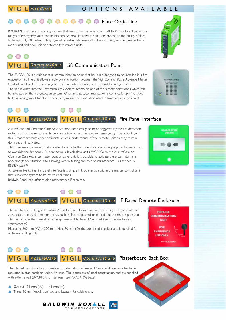
The BVCRALPS is a stainless steel communication point that has been designed to be installed in a fireevacuation lift.The unit allows simple communication between the Vigil CommuniCare Advance MasterControl Panel and those carrying out the evacuation of occupants of disabled refuge areas.The unit is wired into the CommuniCare Advance system on one of the remote point loops which canbe activated by the fire detection system. Once activated, communication is continually ‘open’ to allowbuilding management to inform those carrying out the evacuation which refuge areas are occupied.
The unit has been designed to allow AssureCare and CommuniCare remotes (not CommuniCareAdvance) to be used in external areas, such as fire escapes, balconies and multi-storey car parks, etc.This unit adds further flexibility to the systems and, by being IP66 rated, keeps the electronicsweatherproof.Measuring 200 mm (W) x 200 mm (H) x 80 mm (D), the box is red in colour and is supplied forsurface-mounting only.
BVCROPT is a din-rail mounting module that links to the Baldwin Boxall CANBUS data found within ourranges of emergency voice communication systems. It allows the link (dependent on the quality of fibre)to be up to 4,800 metres in length, which is extremely beneficial if there is a long run between either amaster unit and slave unit or between two remote units.
AssureCare and CommuniCare Advance have been designed to be triggered by the fire detectionsystem so that the remote units become active upon an evacuation emergency. The advantage ofthis is that it prevents either accidental or deliberate misuse of the remote units as they remaindormant until activated.This does mean, however, that in order to activate the system for any other purpose it is necessaryto override the fire panel. By connecting a ‘break glass’ unit (BVCRBG) to the AssureCare orCommuniCare Advance master control panel unit, it is possible to activate the system during anon-emergency situation, also allowing weekly testing and routine maintenance – as set out inBS5839 part 9.An alternative to the fire panel interface is a simple link connection within the master control unitthat allows the system to be active at all times.Baldwin Boxall can offer routine maintenance if required.
The plasterboard back box is designed to allow AssureCare and CommuniCare remotes to bemounted in stud partition walls with ease. The boxes are of steel construction and are suppliedwith either a red (BVCRFBR) or stainless steel (BVCRFBS) bezel.
� Cut out 131 mm (W) x 141 mm (H).� Three 20 mm ‘knock outs’ top and bottom for cable entry.
IP Rated Remote Enclosure
Lift Communication Point
Plasterboard Back Box
Fibre Optic Link
Fire Panel Interface

12
Typica l 32 way AssureCare/CommuniCare System with Master and Slave panels
LOOP 1
32 WAY MASTER PANEL
32 WAY SLAVE PANEL
R1R1
R2R2
R3R3
R4R4
R5R5
R6R6
R7R7
R8R8
R9R9
R10R10
R11R11
R12R12
R13R13
R14R14
R15R15
R16R16
LOOP 2
LOOP 1 ~ Remotes 1 to 16 LOOP 2 ~ Remotes 1 to 16

13
Typical 32 way FireCare System with Master and Slave panels using fibre interfaces
A B C D
A B C D
32 WAY MASTER PANEL
32 WAY SLAVE PANEL
R31
R32
R5
R4
R18
R19R23
R3 R20
R30 R29 R28 R27 R26 R25 R24
R8R7R6 R9 R10 R11 R12 R13 R14 R15 R16 R17
R1R2 R21R22
BVCROPT
BVCROPT
TR
AN
SMIT
RE
CE
IVE
LOOP 2 ~ Remotes 23 to 32
LOOP 1 ~ Remotes 1 to 22
TR
AN
SMIT
RE
CE
IVE
14
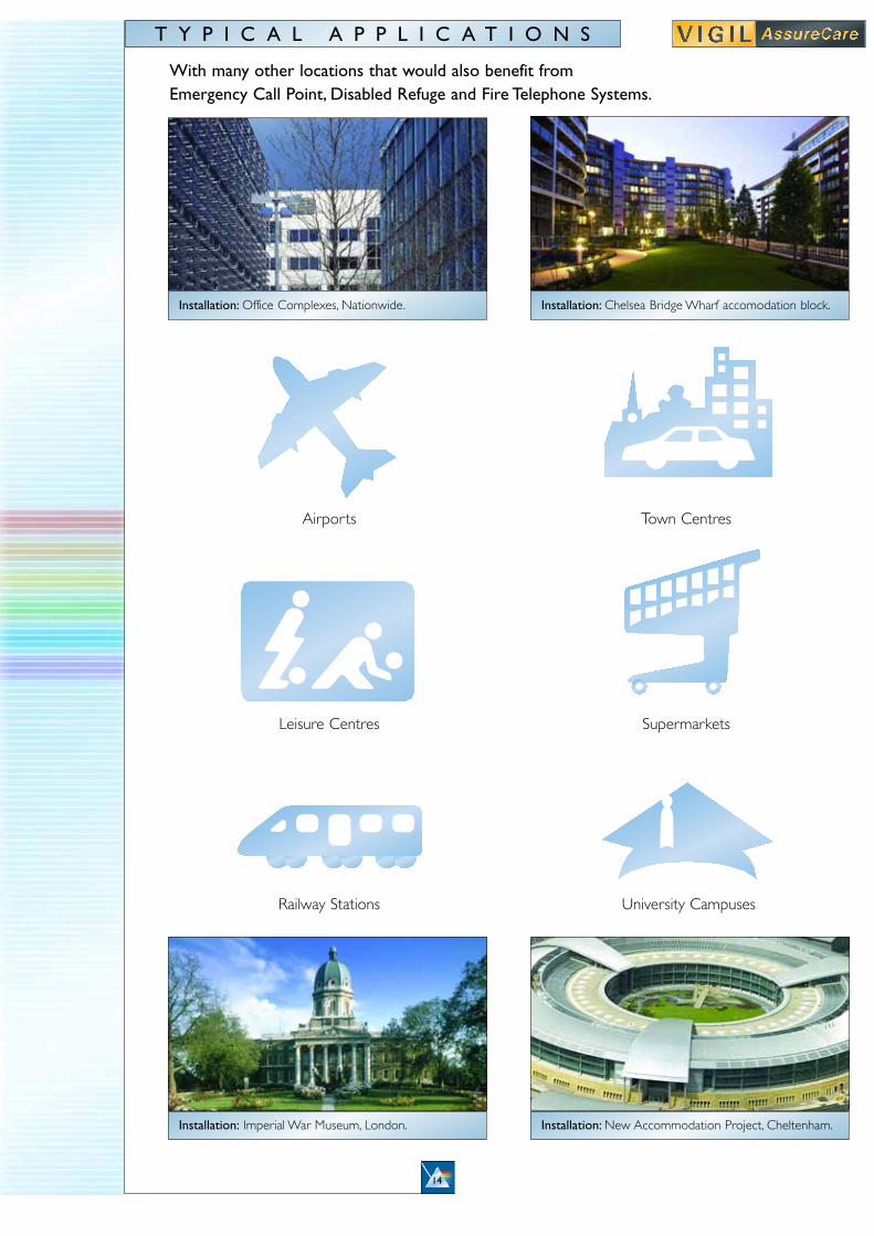
With many other locations that would also benefit from Emergency Call Point, Disabled Refuge and Fire Telephone Systems.
Installation: Imperial War Museum, London. Installation: New Accommodation Project, Cheltenham.
Installation: Office Complexes, Nationwide. Installation: Chelsea Bridge Wharf accomodation block.
T Y P I C A L A P P L I C A T I O N S
Airports
Leisure Centres
Railway Stations
Town Centres
Supermarkets
University Campuses
15
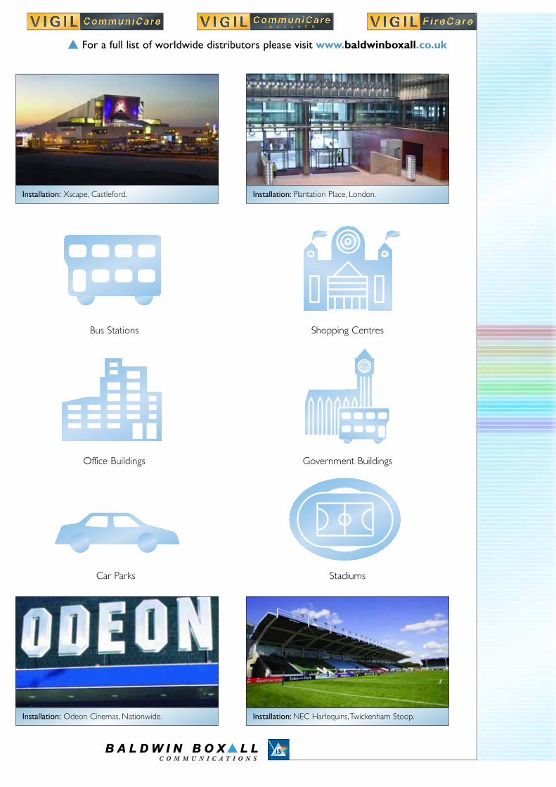
Installation: Odeon Cinemas, Nationwide. Installation: NEC Harlequins,Twickenham Stoop.
Installation: Xscape, Castleford. Installation: Plantation Place, London.
Bus Stations
Office Buildings
Car Parks
� For a full list of worldwide distributors please visit www.baldwinboxall.co.uk
Shopping Centres
Government Buildings
Stadiums
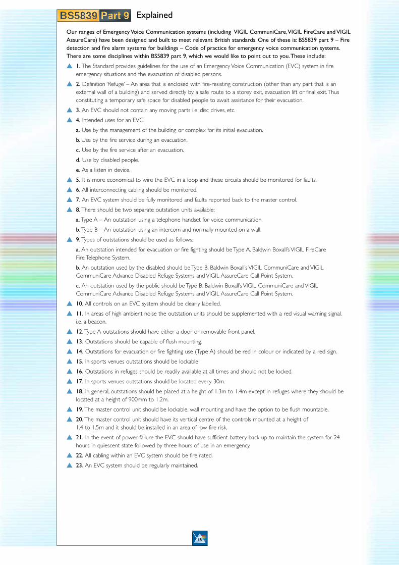
Our ranges of Emergency Voice Communication systems (including VIGIL CommuniCare,VIGIL FireCare and VIGILAssureCare) have been designed and built to meet relevant British standards. One of these is: BS5839 part 9 – Firedetection and fire alarm systems for buildings – Code of practice for emergency voice communication systems.There are some disciplines within BS5839 part 9, which we would like to point out to you.These include:
� 1. The Standard provides guidelines for the use of an Emergency Voice Communication (EVC) system in fire emergency situations and the evacuation of disabled persons.
� 2. Definition ‘Refuge’ – An area that is enclosed with fire-resisting construction (other than any part that is an external wall of a building) and served directly by a safe route to a storey exit, evacuation lift or final exit.Thus constituting a temporary safe space for disabled people to await assistance for their evacuation.
� 3. An EVC should not contain any moving parts i.e. disc drives, etc.
� 4. Intended uses for an EVC:
a. Use by the management of the building or complex for its initial evacuation.
b. Use by the fire service during an evacuation.
c. Use by the fire service after an evacuation.
d. Use by disabled people.
e. As a listen in device.
� 5. It is more economical to wire the EVC in a loop and these circuits should be monitored for faults.
� 6. All interconnecting cabling should be monitored.
� 7. An EVC system should be fully monitored and faults reported back to the master control.
� 8. There should be two separate outstation units available:
a. Type A – An outstation using a telephone handset for voice communication.
b. Type B – An outstation using an intercom and normally mounted on a wall.
� 9. Types of outstations should be used as follows:
a. An outstation intended for evacuation or fire fighting should be Type A. Baldwin Boxall’s VIGIL FireCareFire Telephone System.
b. An outstation used by the disabled should be Type B. Baldwin Boxall’s VIGIL CommuniCare and VIGIL CommuniCare Advance Disabled Refuge Systems and VIGIL AssureCare Call Point System.
c. An outstation used by the public should be Type B. Baldwin Boxall’s VIGIL CommuniCare and VIGIL CommuniCare Advance Disabled Refuge Systems and VIGIL AssureCare Call Point System.
� 10. All controls on an EVC system should be clearly labelled.
� 11. In areas of high ambient noise the outstation units should be supplemented with a red visual warning signal.i.e. a beacon.
� 12. Type A outstations should have either a door or removable front panel.
� 13. Outstations should be capable of flush mounting.
� 14. Outstations for evacuation or fire fighting use (Type A) should be red in colour or indicated by a red sign.
� 15. In sports venues outstations should be lockable.
� 16. Outstations in refuges should be readily available at all times and should not be locked.
� 17. In sports venues outstations should be located every 30m.
� 18. In general, outstations should be placed at a height of 1.3m to 1.4m except in refuges where they should be located at a height of 900mm to 1.2m.
� 19. The master control unit should be lockable, wall mounting and have the option to be flush mountable.
� 20. The master control unit should have its vertical centre of the controls mounted at a height of 1.4 to 1.5m and it should be installed in an area of low fire risk.
� 21. In the event of power failure the EVC should have sufficient battery back up to maintain the system for 24 hours in quiescent state followed by three hours of use in an emergency.
� 22. All cabling within an EVC system should be fire rated.
� 23. An EVC system should be regularly maintained.
16
Explained

Our Disabled Refuge Systems,VIGIL CommuniCare and VIGIL CommuniCare Advance, have been designed andbuilt to meet relevant British standards, one of these is: BS5588 part 8 – Fire precautions in the design,construction and use of buildings - Code of practice for the means of escape for disabled people.There are somedisciplines, which we would like to point out to you.These include:
� 1. The standard applies to all buildings except single family dwellings, flats and maisonettes and buildings used to house multiple occupation.
� 2. Definition ‘Refuge’ – An area that is enclosed with fire-resisting construction (other than any part that is an external wall of a building) and served directly by a safe route to a storey exit, evacuation lift or final exit, thus constituting a temporary safe space for disabled people to await assistance for their evacuation.
� 3. Wheelchair users will not be able to use stairways without assistance. For this reason it is necessary to provide ‘refuge’ on each protected stairway affording egress from each storey and each final exit leading onto a flight of stairs.
� 4. The minimum space for a refuge needs to be at least 900mm X 1400mm, as it needs to be of sufficient size to allow a wheelchair to manoeuvre.
� 5. Examples of satisfactory refuges:
a. An enclosure such as a compartment, protected lobby, protected corridor or protected stairway.
b. An area in the open air such as a flat roof, balcony, podium or similar place sufficiently protected (or remote) from any fire risk and provided with its own means of escape.
� 6. All refuges must have a minimum of 30 minutes fire-resisting separation and a FD 30S type fire door.
� 7. Where a refuge is a protected stairway, protected lobby or protected corridor the following should apply:
a. The wheelchair space should not reduce the width of the escape route.
b. Where the wheelchair space is within a protected stairway access to the wheelchair space will not obstruct the flow of persons escaping.
� 8. When the number and locations of refuges have been decided the essential requirement for independent communication between the occupants and evacuation management personnel need to be met.
� 9. The wheelchair user in each refuge needs to be assured that the building management knows of their presence there.To meet these needs there needs to be:
a. A system of two way communication between those people.
b. The two-way communication system needs to be readily operated, by and comprehensible to, disabled people.
17
Explained
B A L DW I N B OX A L L C O M M U N I C AT I O N S L I M I T E D
W e a l d e n I n d u s t r i a l E s t a t e
F a r n i n g h a m R o a d . J a r v i s B r o o k
C r o w b o r o u g h . E a s t S u s s e x . T N 6 2 J R . U K
T e l : + 4 4 ( 0 ) 1 8 9 2 6 6 4 4 2 2
F a x : + 4 4 ( 0 ) 1 8 9 2 6 6 3 1 4 6
e - m a i l : m a i l @ b a l d w i n b o x a l l . c o . u k
w e b s i t e : w w w . b a l d w i n b o x a l l . c o . u k
T H E C O M P L E T E S P E C T R U M O F C O M M U N I C A T I O N S O L U T I O N S
Low Voltage Directive 73/23/EEC as amended by 93/68/EECEMC Directive 89/336/EEC as amended by 92/31/EEC and 93/68/EECApplies only when the items are correctly fitted and operated in or with products of our manufactureand are installed in a recommended enclosure.Cert No. FM41357
06/2006
An emergency call point system which has capabilities to function as a Disabled Refuge System,Emergency Help Point System or a simple Call Point System.
A sophisticated, digital emergency voice communication system which enables buildingmanagement to communicate efficiently with occupied Disabled Refuge Areas.
Specifically designed for operation by a disabled person within a disabled refuge area and differssignificantly from the standard VIGIL CommuniCare.
A fire telephone system, which has been developed in accordance with BS5839 part 9. Under theregulations, in certain circumstances, each stairwell and exit route should have a fire telephonefor use by the staff and emergency services, allowing the building manager, fire chief, etc, to checkthe status of that area during any emergency.
E M E R G E N C Y V O I C EC O M M U N I C A T I O N
S Y S T E M S ( E V C )
Emergency Call Point System
Disabled Refuge System
Advanced Disabled Refuge System
Fire Telephone System