EMERGENCY ALERT SERVICE BULLETIN - Squarespace · EMERGENCY ALERT SERVICE BULLETIN ......
32
EASB Revision 0 2016-06-01 Page 1/32 This document is available on the internet: www.airbushelicopters.com/techpub EMERGENCY ALERT SERVICE BULLETIN SUBJECT: FUSELAGE - MGB suspension bars and MGB suspension bar attachment fittings Check and replacement of attachment components of the Main Gearbox suspension bars HELICOPTER(S) CONCERNED NUMBER Version(s) Civil Military EC225 53A059 LP Revision No. Date of issue Revision 0 2016-06-01 Summary: - Check the condition of the bolts, washers and pins of the MGB suspension bars. - Check the condition of the MGB suspension bar attachment fittings and peel shims. - Replace the screws, concave/convex washers and nuts of the MGB suspension bar attachment fittings. - Replace the screws, washers and nuts of the plates under the fittings. - Check the condition of frames X3855 and X5295 in the area of the plates. Compliance: Airbus Helicopters renders compliance with this ALERT SERVICE BULLETIN mandatory. For the attention of
Transcript of EMERGENCY ALERT SERVICE BULLETIN - Squarespace · EMERGENCY ALERT SERVICE BULLETIN ......

EASB
Revision 0 2016-06-01 Page 1/32 This document is available on the internet: www.airbushelicopters.com/techpub
EMERGENCY
ALERT SERVICE BULLETIN
SUBJECT: FUSELAGE - MGB suspension bars and MGB suspension bar attachment fittings
Check and replacement of attachment components of the Main Gearbox suspension bars
HELICOPTER(S) CONCERNED
NUMBER Version(s)
Civil Military
EC225 53A059 LP
Revision No. Date of issue
Revision 0 2016-06-01 Summary: - Check the condition of the bolts, washers and pins of the MGB suspension bars. - Check the condition of the MGB suspension bar attachment fittings and peel shims. - Replace the screws, concave/convex washers and nuts of the MGB suspension bar attachment fittings. - Replace the screws, washers and nuts of the plates under the fittings. - Check the condition of frames X3855 and X5295 in the area of the plates. Compliance: Airbus Helicopters renders compliance with this ALERT SERVICE BULLETIN mandatory.
For the attention of

EASB
Revision 0 2016-06-01 Page 2/32 This document is available on the internet: www.airbushelicopters.com/techpub
1. PLANNING INFORMATION 1.A. EFFECTIVITY 1.A.1. Helicopters/installed equipment or parts
EC225 helicopters, version LP, delivered before May 31, 2016.
1.A.2. Non-installed equipment or parts
Not applicable.
1.B. ASSOCIATED REQUIREMENTS
Not applicable.
1.C. REASON
Compliance with ALERT SERVICE BULLETIN No. 53A058 and the associated results revealed discrepancies in the torque application method used for the MGB suspension bar attachment fittings, some cases of incorrect washer installation, and torque values which were out of tolerance. It was therefore decided to proceed with the replacement of all the attachment components of the MGB suspension bar attachment fitting and plate assemblies concerned by the torque application, in order to ensure that the installation complies with the definition. Compliance with this ALERT SERVICE BULLETIN cancels the instructions given in ALERT SERVICE BULLETIN No. 53A058.
1.D. DESCRIPTION
Compliance with this ALERT SERVICE BULLETIN consists in: - checking the condition of the bolts, washers and pins of the MGB suspension bars, - checking the condition of the MGB suspension bar attachment fittings and peel shims, - replacing the screws, concave/convex washers and nuts of the MGB suspension bar attachment fittings, - replacing the screws, washers and nuts of the plates under the fittings, - checking for cracks in frames X3855 and X5295, in the area located under the plates.

EASB
Revision 0 2016-06-01 Page 3/32 This document is available on the internet: www.airbushelicopters.com/techpub
1.E. COMPLIANCE 1.E.1. Compliance at H/C manufacturer level
Not applicable.
1.E.2. Compliance in service
The work on the helicopter is to be performed by the operator. Helicopters/installed equipment or parts: - For helicopters on which compliance with ALERT SERVICE BULLETIN No. 53A058 has not been ensured:
. compliance with ALERT SERVICE BULLETIN No. 53A058 is not necessary,
. comply with paragraph 3. (except for paragraph 3.B.10.) before the next flight. Airbus Helicopters authorizes ferry flights (flights without transportation of passengers) to a maintenance center for compliance with paragraph 3.
- For helicopters on which compliance with ALERT SERVICE BULLETIN No. 53A058 has been ensured:
. comply with paragraph 3. (except for paragraphs 3.B.1. and 3.B.10.) within 75 flying hours following compliance with ALERT SERVICE BULLETIN No. 53A058.
- For helicopters stored for more than 6 months since the issue of ALERT SERVICE BULLETIN No. 53A058,
regardless of whether compliance has been ensured or not: . compliance with ALERT SERVICE BULLETIN No. 53A058 is not necessary, . comply with paragraph 3. (except for paragraph 3.B.10.) before the next flight.
Then, - For all helicopters, comply with paragraph 3.B.10. after at least 10 flying hours and no later than 50 flying
hours following compliance with paragraph 3. Non-installed equipment or parts: Not applicable.
1.F. APPROVAL
Approval of modifications: Not applicable. Approval of this document: The technical information contained in this ALERT SERVICE BULLETIN Revision 0 was approved on June 01, 2016 under the authority of EASA Design Organization Approval No. 21J.056 for helicopters of civil versions subject to an Airworthiness Certificate. The technical information contained in this ALERT SERVICE BULLETIN Revision 0 was approved on June 01, 2016 under the prerogatives of the recognition of design capability FRA21J-002-DGA for French Government helicopters.
EASB
Revision 0 2016-06-01 Page 4/32 This document is available on the internet: www.airbushelicopters.com/techpub
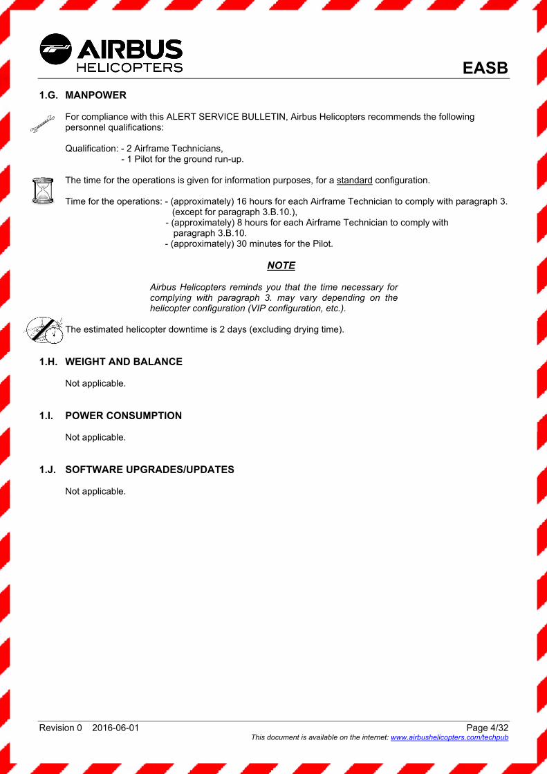
1.G. MANPOWER
For compliance with this ALERT SERVICE BULLETIN, Airbus Helicopters recommends the following personnel qualifications: Qualification: - 2 Airframe Technicians,
- 1 Pilot for the ground run-up. The time for the operations is given for information purposes, for a standard configuration. Time for the operations: - (approximately) 16 hours for each Airframe Technician to comply with paragraph 3.
(except for paragraph 3.B.10.), - (approximately) 8 hours for each Airframe Technician to comply with
paragraph 3.B.10. - (approximately) 30 minutes for the Pilot.
NOTE
Airbus Helicopters reminds you that the time necessary for complying with paragraph 3. may vary depending on the helicopter configuration (VIP configuration, etc.).
The estimated helicopter downtime is 2 days (excluding drying time). 1.H. WEIGHT AND BALANCE
Not applicable.
1.I. POWER CONSUMPTION
Not applicable.
1.J. SOFTWARE UPGRADES/UPDATES
Not applicable.
EASB
Revision 0 2016-06-01 Page 5/32 This document is available on the internet: www.airbushelicopters.com/techpub
1.K. REFERENCES
The documents required for compliance with this ALERT SERVICE BULLETIN are as follows: Aircraft Maintenance Manual (MMA): Task: 53-00-00-611: GENERAL - General Standard Maintenance Instructions Task: 53-26-00-061: FITTINGS AND MOUNTS - MGB Attachment Fitting Removal-Installation Task: 60-00-00-212: ROTOR STANDARD PRACTICES - Checking a Magnetic Component Task: 60-00-00-221: ROTOR STANDARD PRACTICES - Damage Tolerance Task: 63-00-00-611: MAIN TRANSMISSION POWER SYSTEM - General Standard Maintenance
Instructions Task: 63-24-01-061: MAIN GEARBOX OIL FILTER - Removal - Installation of Filter Cartridge Task: 63-32-00-061: MGB SUSPENSION BARS - Suspension Bars Removal - Installation Standard Practices Manual (MTC): Work Card: 20.02.05.404: Joining - Joining by bolts and nuts Work Card: 20.02.06.404: Safetying and locking assemblies - Safetying with cotter pins Work Card: 20.02.09.101: Crack detection - Crack detection through dye-penetrant inspection: General Work Card: 20.02.09.601: Crack detection - Checking structural parts/components using the dye penetrant
procedure Work Card: 20.04.01.102: Cleaning - Use of cleaning products on individual parts and on aircraft Work Card: 20.05.01.222: General sealing procedures - Application of PR 1771 B2 sealant Work Card: 20.05.01.227: General sealing procedures - Application of Jointing Compound CA 1010 Work Card: 20.07.02.201: Safety instructions - Helicopter parked in a repair shop Work Card: 20.07.03.408: Technical instructions - Appearance checks on an aircraft after an inspection or
repair Work Card: 20.08.02.601: Monitoring of lubricating oils and hydraulic fluids - Spectrometric analysis of
lubricating oils used in mechanical assemblies
1.L. OTHER AFFECTED PUBLICATIONS
Not applicable.
1.M. PART INTERCHANGEABILITY OR MIXABILITY
Not applicable.
EASB
Revision 0 2016-06-01 Page 6/32 This document is available on the internet: www.airbushelicopters.com/techpub
2. EQUIPMENT OR PARTS INFORMATION 2.A. EQUIPMENT OR PARTS: PRICE - AVAILABILITY - PROCUREMENT
For any information concerning the kits and/or components or for assistance, contact the Airbus Helicopters Network Sales & Customer Relations Department. Order as required from: Airbus Helicopters Etablissement de Marignane Direction Ventes et Relations Client 13725 MARIGNANE CEDEX FRANCE
NOTE 1 On the purchase order, please specify the mode of transport, the destination and the serial numbers of the helicopters to be modified.
NOTE 2 For ALERT SERVICE BULLETINS, order by: Telex: HELICOP 410 969F Fax: +33 (0)4.42.85.99.96.
2.B. LOGISTIC INFORMATION
Not applicable.

EASB
Revision 0 2016-06-01 Page 7/32 This document is available on the internet: www.airbushelicopters.com/techpub
2.C. EQUIPMENT OR PARTS REQUIRED PER HELICOPTER/COMPONENT 2.C.1. Kits to be ordered for one helicopter or one assembly:
Designation Qty New P/N Item Former P/N → Instruction
Kit for MGB
suspension bar fitting attachment
332A53A0590071
Front attachment screw 4 332A22-1613-21 1 Rear attachment screw 8 332A22-1614-20 2
Cotter pin 12 23310CA020025 3 Hexagonal castle nut 16 ASNA0045BC100L 4 Hexagonal castle nut 8 ASNA0045BC120L 5
Hexagonal head screw 4 22201BE060010L 6 Hexagonal head screw 8 22201BE060012L 7 Hexagonal head screw 4 22201BE060015L 8
Flat washer 32 23112AG060LE 9 Flat washer 16 23118AG060LE 10 Flat washer 8 23119AG060LE 11
Self-locking hexagonal nut
32 ASN52320BH060N 12
Hexagonal head screw 4 22201BE060023L 13 Hexagonal head screw 8 22201BE060020L 14 Hexagonal head screw 4 22201BE060016L 15
Flat washer 9 23111AG050LE 16 Hexagonal head screw 8 22201BE050016L 17 Hexagonal head screw 4 22201BE050018L 18
Flat washer 28 23112AG050LE 19 Flat washer 19 23118AG050LE 20
Self-locking hexagonal nut
28 ASN52320BH050N 21
Hexagonal head screw 12 22201BE070020L 22 Flat washer 12 23134AG070LE 23
Self-locking hexagonal nut
12 ASN52320BH070N 24
Flat washer 12 23112AG070LE 25 Flat washer 4 23111AG060LE 26
Hexagonal head screw 4 22201BE080014L 27 Flat washer 8 23112AG080LE 28 Flat washer 8 23118AG080LE 29
Self-locking hexagonal nut
8 ASN52320BH080N 30
Hexagonal head screw 4 22201BE080012L 31 Hexagonal head screw 4 22201BE050026L 32 Hexagonal head screw 12 22201BE050014L 33
EASB
Revision 0 2016-06-01 Page 8/32 This document is available on the internet: www.airbushelicopters.com/techpub
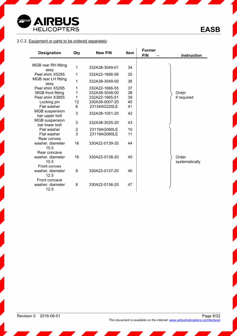
2.C.2. Equipment or parts to be ordered separately:
Designation Qty New P/N Item Former P/N → Instruction
MGB rear RH fitting
assy 1 332A38-3049-01 34
Order if required Order systematically
Peel shim X5295 1 332A22-1666-56 35 MGB rear LH fitting
assy 1 332A38-3049-00 36
Peel shim X5295 1 332A22-1666-55 37 MGB front fitting 1 332A38-3048-00 38 Peel shim X3855 1 332A22-1665-51 39
Locking pin 12 330A38-0007-20 40 Flat washer 6 23134AG220LE 41
MGB suspension bar upper bolt
3 332A38-1051-20 42
MGB suspension bar lower bolt
3 332A38-3025-20 43
Flat washer 2 23118AG060LE 10 Flat washer 3 23119AG060LE 11 Rear convex
washer, diameter 10.5
16 330A22-0139-20 44
Rear concave washer, diameter
10.5 16 330A22-0138-20 45
Front convex washer, diameter
12.5 8 330A22-0137-20 46
Front concave washer, diameter
12.5 8 330A22-0136-20 47

EASB
Revision 0 2016-06-01 Page 9/32 This document is available on the internet: www.airbushelicopters.com/techpub
2.C.3. Equipment or parts to be ordered according to the repairs carried out
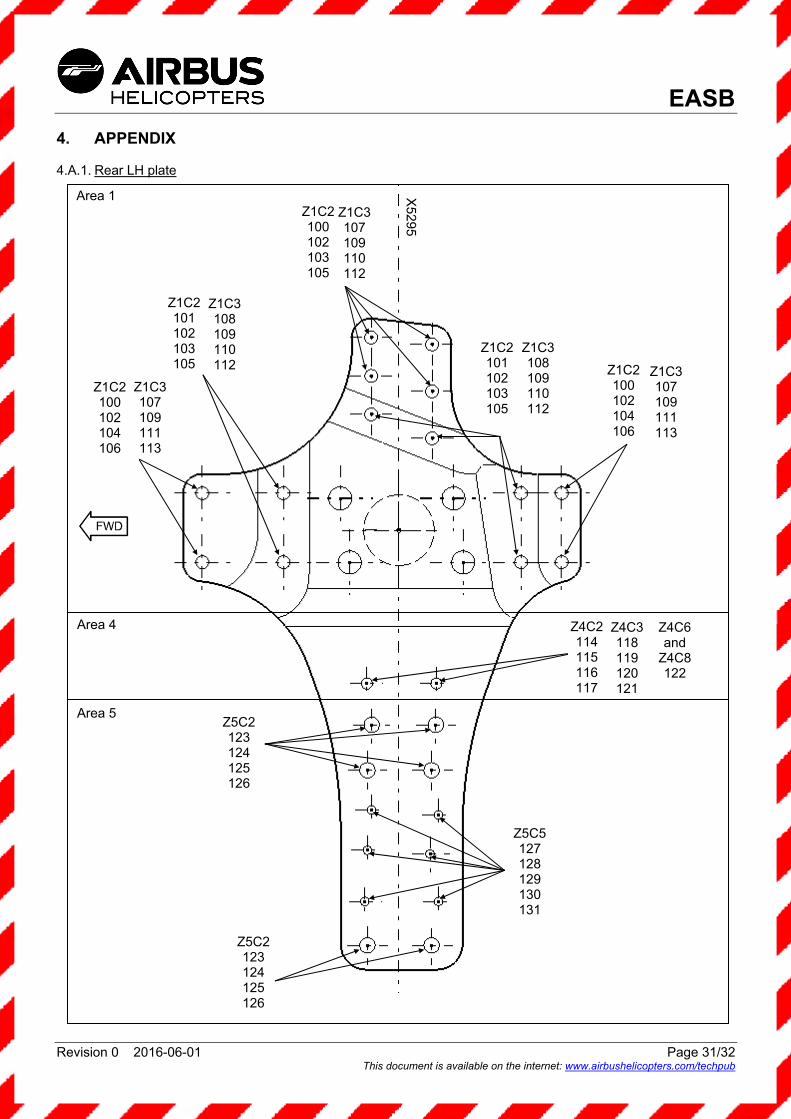
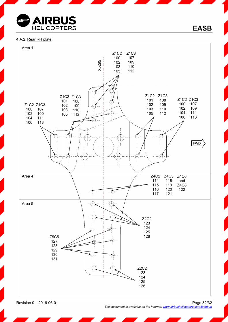
The plates under the MGB suspension bar rear attachment fittings have been modified within the scope of the reinforcement of frame X5295. On some helicopters, the embodiment of this modification may have required the use of repair kits listed below. Before ordering the equipment or parts required for compliance with this ALERT SERVICE BULLETIN, it is recommended to check in the helicopter documents if compliance with Service Bulletin No. 53-003 or the embodiment of modification 0726493 or 0726517 required the use of one or several of the kits below, and to order them if required. For the repair areas, refer to appendices 4.A.1. and 4.A.2. Equipment or parts to be ordered separately for area 1, configuration 2 (Z1C2):
Designation Qty New P/N Item Former P/N Instruction
Hexagonal head screw, Ø 6.35 16 NAS1304-1 100 Hexagonal head screw, Ø 6.35 12 NAS1304-3 101
Self-locking hexagonal nut 28 MS21043-4
102 Corresponds to kit 332A08-0939-0171
Countersunk flat washer, thickness 1.2
20 332A08-0939-AD 103
Flat washer 8 332A08-0939-AE 104 Semi-thick washer, thickness
2.5 20 332A08-0939-AF
105
Thick washer 8 332A08-0939-AG 106 Equipment or parts to be ordered separately for area 1, configuration 3 (Z1C3):
Designation Qty New P/N Item Former P/N Instruction
Hexagonal head screw, Ø 7 16 22201BE070012L 107
Hexagonal head screw, Ø 7 12 22201BE070015L
108 Corresponds to kit 332A08-0939-0271
Self-locking hexagonal nut 28 ASN52320BH070N 109 Flat washer 20 23112AG070LE 110 Flat washer 8 332A08-0939-AM 111 Flat washer 12 23118AG070LE 112 Flat washer 16 23119AG070LE 113
Equipment or parts to be ordered separately for area 4, configuration 2 (Z4C2):
Designation Qty New P/N Item Former P/N Instruction
Hexagonal head screw 4 22201BE070020L 114
Flat washer 4 23112AG070LE
115 Corresponds to kit 332A08-0939-0471
Flat washer 4 23111AG070LE 116 Self-locking hexagonal nut 4 ASN52320BH070N 117

EASB
Revision 0 2016-06-01 Page 10/32 This document is available on the internet: www.airbushelicopters.com/techpub
Equipment or parts to be ordered separately for area 4, configuration 3 (Z4C3):
Designation Qty New P/N Item Former P/N Instruction
Hexagonal head screw, Ø 8 4 22201BE080020L 118
Flat washer 4 23112AG080LE
119 Corresponds to kit 332A08-0939-0571
Flat washer 4 23111AG080LE 120 Self-locking hexagonal nut 4 ASN52320BH080N 121
Equipment or parts to be ordered separately for area 4, configurations 6 and 8 (Z4C6 and Z4C8):
Designation Qty New P/N Item Former P/N Instruction
Patch 4 332A08-0939-21 122
Corresponds to kit 332A08-0939-0671 without FTI bush
Equipment or parts to be ordered separately for area 5, configuration 2 (Z5C2):
Designation Qty New P/N Item Former P/N Instruction
Hexagonal head screw, Ø 8 12 22201BE080020L 123
Flat washer 12 23112AG080LE 124 Corresponds to kit 332A08-0939-0771
Flat washer 12 23111AG080LE 125 Self-locking hexagonal nut 12 ASN52320BH080N 126
Equipment or parts to be ordered separately for area 5, configuration 5 (Z5C5):
Designation Qty New P/N Item Former P/N Instruction
Hexagonal head screw, Ø 6 8 22201BE060016L 127
Hexagonal head screw, Ø 6 4 22201BE060018L 128 Corresponds to kit 332A08-0939-0871
Flat washer 12 23112AG060LE 129 Flat washer 12 23111AG060LE 130
Self-locking hexagonal nut 12 ASN52320BH060N 131

EASB
Revision 0 2016-06-01 Page 11/32 This document is available on the internet: www.airbushelicopters.com/techpub
2.C.4. Consumables to be ordered separately:
As per the Work Cards and Tasks specified in this ALERT SERVICE BULLETIN and the list below:
Designation Qty Consumable P/N CM Item
Anti-corrosion agent A/R CA1010 518 48
Sealing compound A/R PR1771B2 6068 49
The consumables can be ordered separately from the INTERTURBINE AVIATION LOGISTICS company: Website: http://www.interturbine.com Telephone: +49.41.91.809.300 AOG: +49.41.91.809.444
2.D. EQUIPMENT OR PARTS TO BE RETURNED
Not applicable.
EASB
Revision 0 2016-06-01 Page 12/32 This document is available on the internet: www.airbushelicopters.com/techpub
3. ACCOMPLISHMENT INSTRUCTIONS 3.A. GENERAL
- Read and comply with the general standard maintenance instructions for the fuselage structure as per MMA Task 53-00-00-611.
- Read and comply with the general standard maintenance instructions for the main rotor as per MMA Task 63-00-00-611.
- Read and comply with the instructions for joining by bolts and nuts as per MTC Work Card 20.02.05.404. - Read and comply with the instructions for safetying with cotter pins as per MTC Work Card 20.02.06.404. - Read and comply with the cleaning instructions for individual parts and on aircraft as per MTC Work
Card 20.04.01.102.
3.B. WORK STEPS 3.B.1. Preliminary checks
- Check that there are no metal particles on the Main Gearbox (MGB) particle detectors as per MMA Task 60-00-00-212.
- Check that there are no metal particles in the MGB oil filter as per MMA Task 63-24-01-061: . if particles are collected, refer to MTC Work Card 20.08.02.601.
- For helicopters equipped with M'ARMS, download the data and check that no thresholds have been exceeded. Retain this data in case further analysis is needed.
3.B.2. Preliminary steps
- Park the helicopter in a repair shop as per MTC Work Card 20.07.02.201. - Remove and/or open all cowlings, panels, doors and equipment as required for access to the various work
areas.
COMPLY WITH PARAGRAPHS 3.B.3. TO 3.B.8. ON ONE MGB SUSPENSION BAR BEFORE PROCEEDING WITH THE NEXT ONE.
3.B.3. Check of the MGB suspension bars (Figures 1, 2, 3, 5)
As per Figure 5: - Make sure that washer (a) and both pins (b) are installed on upper and lower bolts (c). - Identify these components and associate them with this bolt. - Remove MGB suspension bar (d) as per MMA Task 63-32-00-061.
CAUTION

EASB
Revision 0 2016-06-01 Page 13/32 This document is available on the internet: www.airbushelicopters.com/techpub
- Check the condition of both pins (b):
. if neither of the pins (b) is distorted (Figure 1), leave as is,
. if at least one of the pins (b) is distorted (Figure 1), discard and replace both pins (b).
Correct condition Incorrect condition
Figure 1: Suspension bar pins
- Check the condition of washer (a):
. if there are no pitting marks, leave as is,
. if there are pitting marks (see example in Figure 2), discard and replace washer (a).
Figure 2: Suspension bar washer
- If anomalies are observed at the pins and/or washer, inform the Airbus Helicopters Technical Support Department by: Fax: +33 (0)4.42.85.99.66. or e-mail: [email protected]
b
b
a
EASB
Revision 0 2016-06-01 Page 14/32 This document is available on the internet: www.airbushelicopters.com/techpub
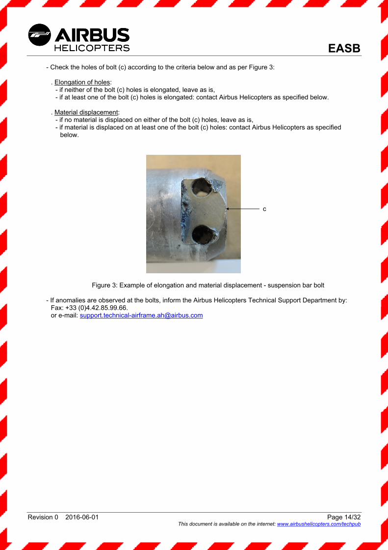
- Check the holes of bolt (c) according to the criteria below and as per Figure 3:
. Elongation of holes: - if neither of the bolt (c) holes is elongated, leave as is, - if at least one of the bolt (c) holes is elongated: contact Airbus Helicopters as specified below.
. Material displacement:
- if no material is displaced on either of the bolt (c) holes, leave as is, - if material is displaced on at least one of the bolt (c) holes: contact Airbus Helicopters as specified
below.
Figure 3: Example of elongation and material displacement - suspension bar bolt
- If anomalies are observed at the bolts, inform the Airbus Helicopters Technical Support Department by: Fax: +33 (0)4.42.85.99.66. or e-mail: [email protected]
c
EASB
Revision 0 2016-06-01 Page 15/32 This document is available on the internet: www.airbushelicopters.com/techpub
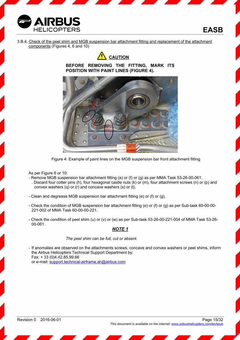
3.B.4. Check of the peel shim and MGB suspension bar attachment fitting and replacement of the attachment
components (Figures 4, 6 and 10)
BEFORE REMOVING THE FITTING, MARK ITS POSITION WITH PAINT LINES (FIGURE 4).
Figure 4: Example of paint lines on the MGB suspension bar front attachment fitting
As per Figure 6 or 10: - Remove MGB suspension bar attachment fitting (e) or (f) or (g) as per MMA Task 53-26-00-061.
. Discard four cotter pins (h), four hexagonal castle nuts (k) or (m), four attachment screws (n) or (p) and convex washers (q) or (r) and concave washers (s) or (t).
- Clean and degrease MGB suspension bar attachment fitting (e) or (f) or (g). - Check the condition of MGB suspension bar attachment fitting (e) or (f) or (g) as per Sub-task 60-00-00-
221-002 of MMA Task 60-00-00-221. - Check the condition of peel shim (u) or (v) or (w) as per Sub-task 53-26-00-221-004 of MMA Task 53-26-
00-061. NOTE 1
The peel shim can be full, cut or absent.
- If anomalies are observed on the attachments screws, concave and convex washers or peel shims, inform
the Airbus Helicopters Technical Support Department by: Fax: + 33 (0)4.42.85.99.66 or e-mail: [email protected]
CAUTION
EASB
Revision 0 2016-06-01 Page 16/32 This document is available on the internet: www.airbushelicopters.com/techpub
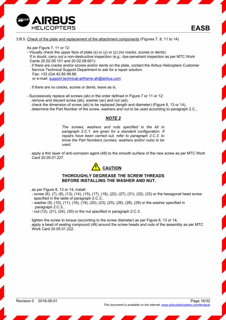
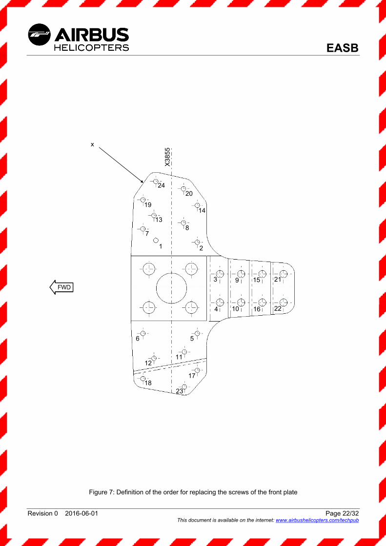
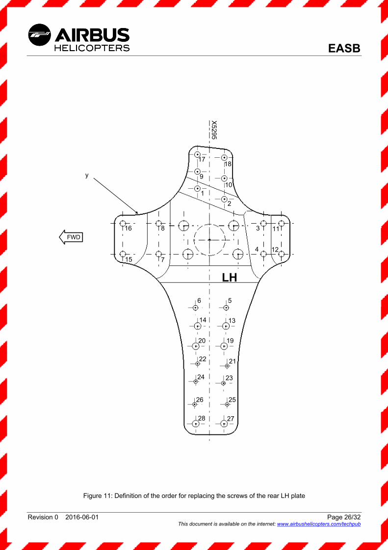
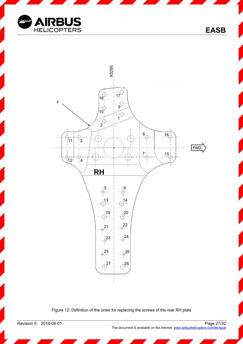
3.B.5. Check of the plate and replacement of the attachment components (Figures 7, 8, 11 to 14)
As per Figure 7, 11 or 12: - Visually check the upper face of plate (x) or (y) or (z) (no cracks, scores or dents):
If in doubt, carry out a non-destructive inspection (e.g.: dye-penetrant inspection as per MTC Work Cards 20.02.09.101 and 20.02.09.601): . if there are cracks and/or scores and/or dents on the plate, contact the Airbus Helicopters Customer
Service Technical Support Department to ask for a repair solution: Fax: +33 (0)4.42.85.99.66. or e-mail: [email protected]
. if there are no cracks, scores or dents, leave as is.
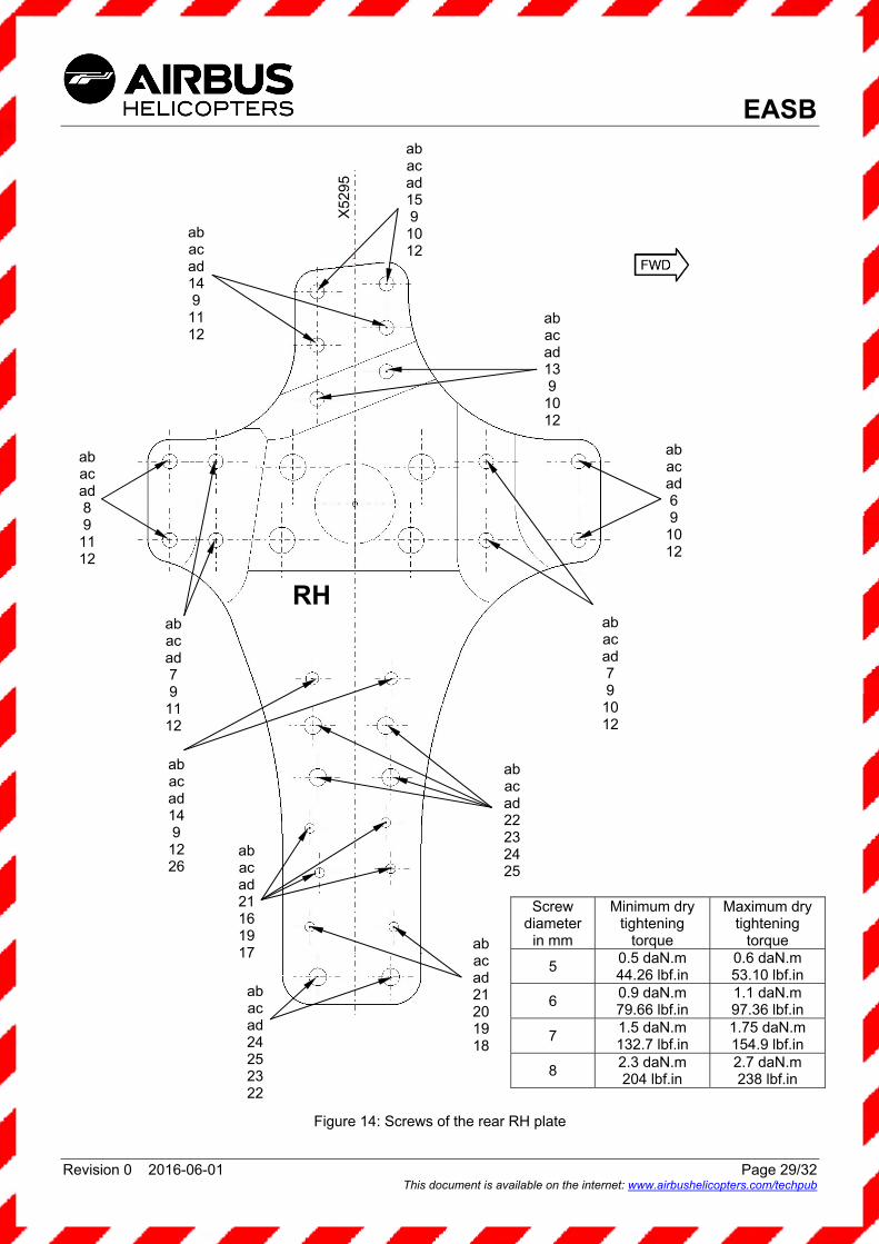
- Successively replace all screws (ab) in the order defined in Figure 7 or 11 or 12: . remove and discard screw (ab), washer (ac) and nut (ad), . check the dimension of screw (ab) to be replaced (length and diameter) (Figure 8, 13 or 14), . determine the Part Number of the screw, washers and nut to be used according to paragraph 2.C.,
NOTE 2
The screws, washers and nuts specified in the kit in paragraph 2.C.1. are given for a standard configuration. If repairs have been carried out, refer to paragraph 2.C.3. to know the Part Numbers (screws, washers and/or nuts) to be used.
. apply a thin layer of anti-corrosion agent (48) to the smooth surface of the new screw as per MTC Work
Card 20.05.01.227.
THOROUGHLY DEGREASE THE SCREW THREADS BEFORE INSTALLING THE WASHER AND NUT.
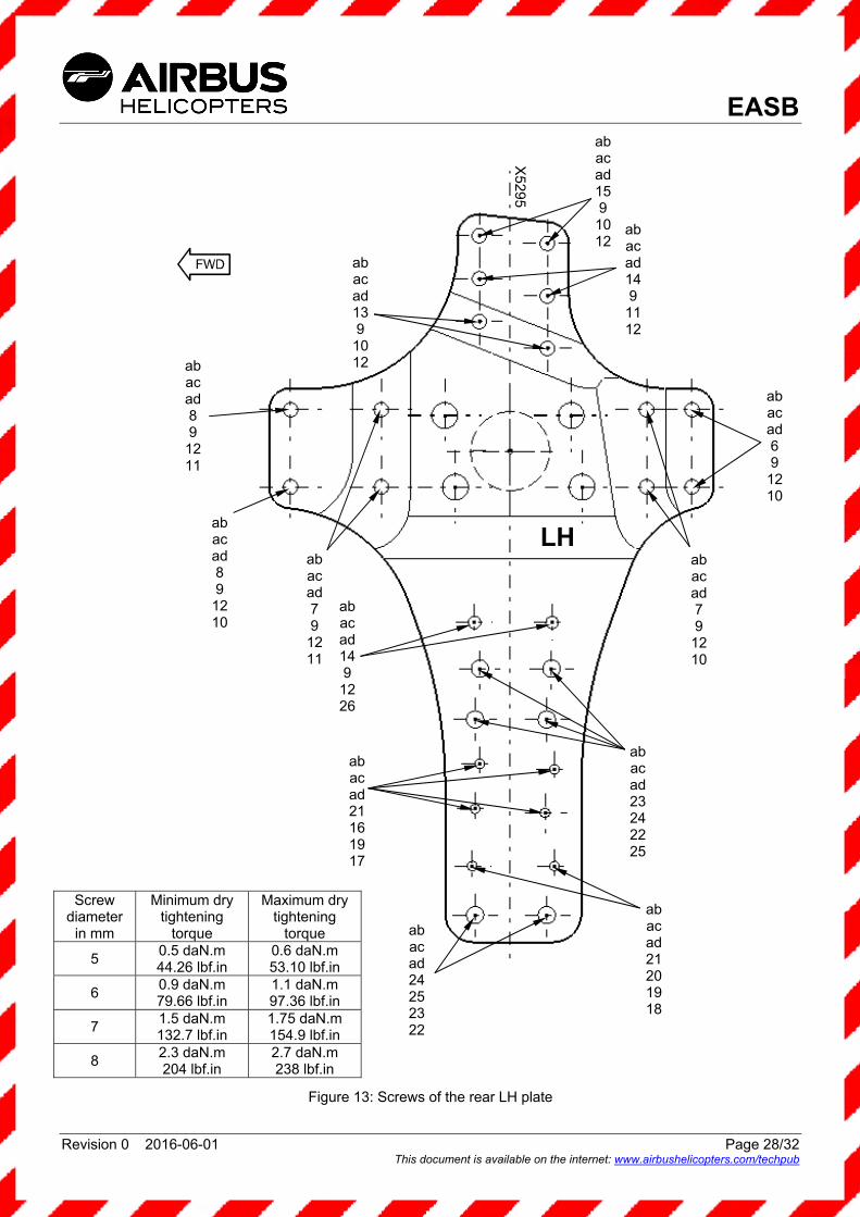
. as per Figure 8, 13 or 14, install:
- screw (6), (7), (8), (13), (14), (15), (17), (18), (22), (27), (31), (32), (33) or the hexagonal head screw specified in the table of paragraph 2.C.3.,
- washer (9), (10), (11), (16), (19), (20), (23), (25), (26), (28), (29) or the washer specified in paragraph 2.C.3.,
- nut (12), (21), (24), (30) or the nut specified in paragraph 2.C.3.
. tighten the screw to torque (according to the screw diameter) as per Figure 8, 13 or 14,
. apply a bead of sealing compound (49) around the screw heads and nuts of the assembly as per MTC Work Card 20.05.01.222.
CAUTION

EASB
Revision 0 2016-06-01 Page 17/32 This document is available on the internet: www.airbushelicopters.com/techpub
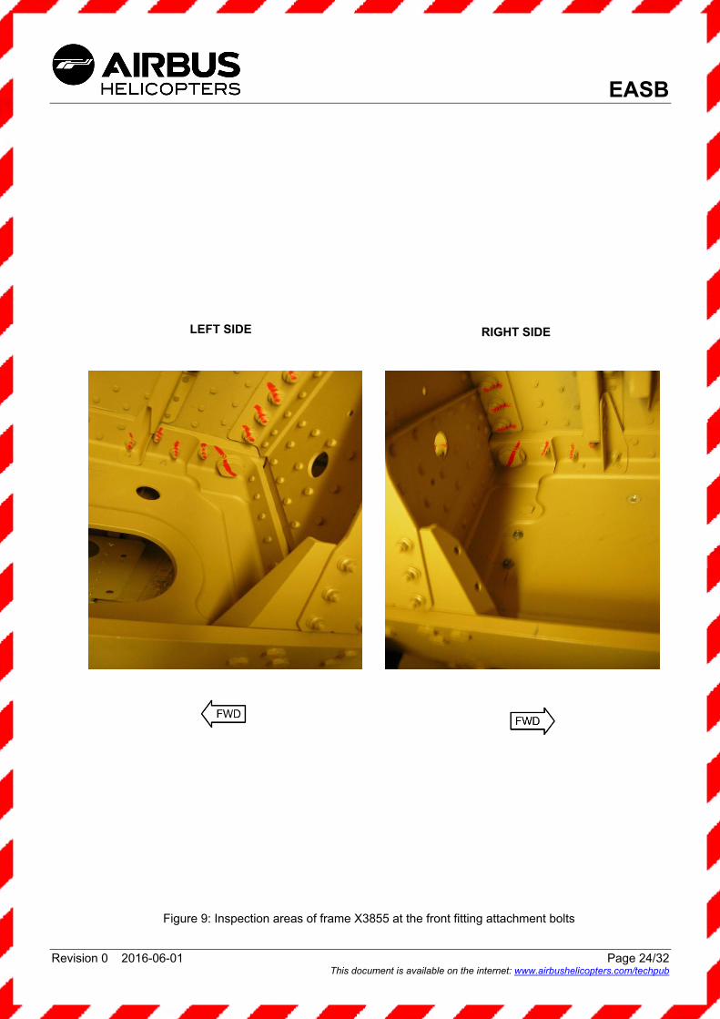
3.B.6. Check of the frames (Figures 9 and 15)
3.B.6.a. Check of frame X3855 (Front fitting)
- Visually check that there are no cracks in frame X3855 at the fitting attachment (see photos in
Figure 9). If in doubt, carry out a non-destructive inspection (e.g.: dye-penetrant inspection as per MTC Work Cards 20.02.09.101 and 20.02.09.601): . if there are cracks in frame X3855, stop flights and contact the Airbus Helicopters Customer Service
Technical Support Department to ask for a repair solution: Fax: +33 (0)4.42.85.99.66. or e-mail: [email protected]
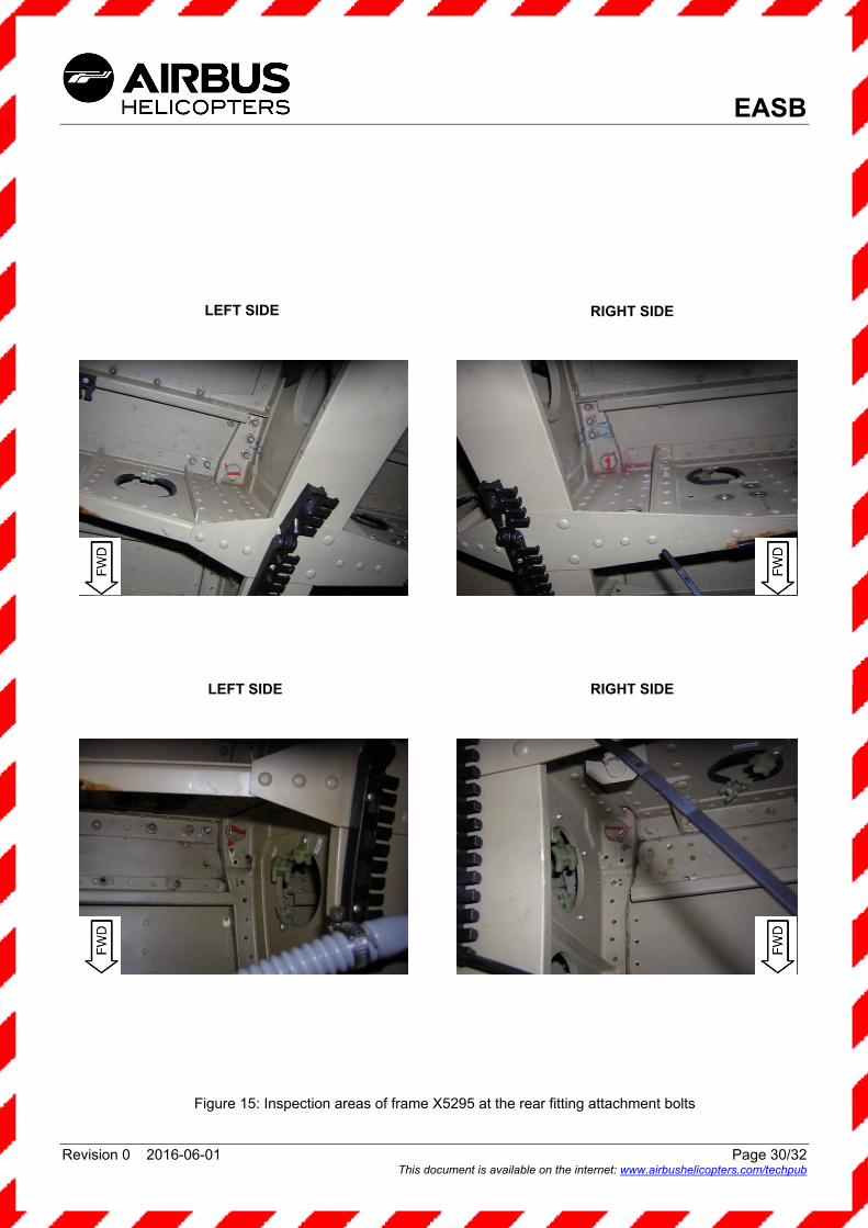
3.B.6.b. Check of frame X5295 (Rear fittings)
- Visually check that there are no cracks in frame X5295 at the fitting attachment (see photos in
Figure 15). If in doubt, carry out a non-destructive inspection (e.g.: dye-penetrant inspection as per MTC Work Cards 20.02.09.101 and 20.02.09.601): . if there are cracks in frame X5295, stop flights and contact the Airbus Helicopters Customer Service
Technical Support Department to ask for a repair solution: Fax: +33 (0)4.42.85.99.66. or e-mail: [email protected]
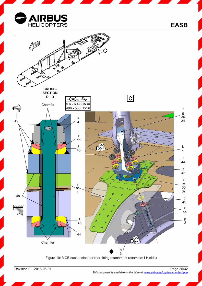
3.B.7. MGB suspension bar fitting installation (Figures 4, 6 and 10)
- As per Figure 6 or 10, install the MGB suspension bar attachment fitting:
. apply anti-corrosion agent (48) to the contact faces of MGB suspension bar fitting (e) or (38), (f) or (36), (g) or (34) and plate (x), (y) and (z),
. install peel shim (u) or (39), (v) or (37), (w) or (35) as identified during removal,
. install MGB suspension bar fitting (e) or (38), (f) or (36), (g) or (34) as identified during removal, ensuring the locating pin is correctly engaged in the plate,
. fit the following components on attachment screw (1) or (2):
- a convex washer (46) or (44), - a concave washer (47) or (45), and ensure the correct stacking of washers and the correct position of the lower chamfer under the screw head, in accordance with Figure 6 or 10.
. apply anti-corrosion agent (48) to the smooth part of attachment screws (1) or (2),
. clean and degrease the threads of screws (1), (2) and the visible parts of convex washers (46), (44) and concave washers (47), (45),
. from inside the cabin, position equipped attachment screws (1) or (2), . hold the assembly in place,
THOROUGHLY CLEAN THE SCREW THREADS BEFORE INSTALLING WASHERS AND NUT.
. on the transmission deck, install on each attachment screw (1) or (2) concave washers (47) or (45), then
convex washers (46) or (44), . ensure the correct stacking of washers and the correct position of the lower chamfer under the nut, in
accordance with Figure 6 or 10, . install nuts (5) or (4) by hand, without tightening, . make sure that MGB suspension bar fitting (e) or (38), (f) or (36), (g) or (34) is correctly positioned with
respect to the paint mark (see example in Figure 4),
CAUTION

EASB
Revision 0 2016-06-01 Page 18/32 This document is available on the internet: www.airbushelicopters.com/techpub
. pre-tighten each screw to approximately half of the torque value (by tightening crosswise), . tighten each screw to torque as per Figure 6 or 10 (by tightening crosswise),
Reminder: Torque-tighten in the following manner: - tighten the hexagonal castle nut to the minimum torque value, - if possible, install the cotter pin, - otherwise loosen the hexagonal castle nut by a quarter of a turn, then continue tightening from the
minimum torque value without exceeding the maximum torque value, in order to reach the cotter pin hole.
NOTE 3
The need to align a slot with a cotter pin hole does not justify exceeding the maximum torque value.
. if the cotter pin hole cannot be reached, replace the nut and repeat the tightening procedure, . install cotter pin (3).
NOTE 4
The use of an electronic torque wrench (e.g.: FACOM type E306) facilitates the installation of cotter pin (3) in compliance with the torque range. The video available under the following link presents the essential steps of this ALERT SERVICE BULLETIN, including the use of the electronic torque wrench. http://www.dailymotion.com/video/k6LoziNNMMaj4YhV1KA
. apply a bead of sealing compound (49) around MGB suspension bar fittings (e) or (38), (f) or (36), (g) or
(34), at the seating plane, as per MTC Work Card 20.05.01.222, . protect the visible part of the assembly:
- convex washers (46) or (44), - concave washers (47) or (45), - hexagonal castle nuts (5) and (4), - attachment screw (1) or (2), using sealing compound (49) as per MTC Work Card 20.05.01.222.
3.B.8. MGB suspension bar installation (Figure 5)
ONCE PARAGRAPHS 3.B.2. TO 3.B.7. HAVE BEEN COMPLIED WITH ON THE THREE MGB SUSPENSION BARS, REMOVE THE FLEXIBLE MOUNTING PLATE SHIMS INSTALLED DURING REMOVAL OF THE MGB SUSPENSION BARS.
- Install MGB suspension bar (d) (Figure 5) as per MMA Task 63-32-00-061.
NOTE 5
For front suspension bar (d), installing lower bolt (c) from the RH to the LH side facilitates the installation of pins (b).
CAUTION
EASB
Revision 0 2016-06-01 Page 19/32 This document is available on the internet: www.airbushelicopters.com/techpub
3.B.9. Final steps
- Install and/or close all cowlings, panels, doors and equipment removed and/or opened during the preliminary steps.
- Check the appearance of the helicopter as per MTC Work Card 20.07.03.408.
3.B.10. Readjustment of the tightening torque on the MGB suspension bar attachment fittings (Figures 6 and 10)
- For each of the nuts (one after the other) of the MGB suspension bar fitting screws: . remove the sealing compound from around the nut, washers and screw, . remove and discard cotter pin (h), . readjust the tightening torque of hexagonal castle nut (k) or (m) as per Figure 6 or 10 and MTC Work
Card 20.02.05.404 (by tightening crosswise).
Reminder: Torque-tighten in the following manner: - tighten hexagonal castle nut to the minimum torque value, - if possible, install the cotter pin, - otherwise loosen the hexagonal castle nut by a quarter of a turn, then continue tightening from the
minimum torque value without exceeding the maximum torque value, in order to reach the cotter pin hole.
NOTE 6
The need to align a slot with a cotter pin hole does not justify exceeding the maximum torque value.
. if the cotter pin hole cannot be reached, discard hexagonal castle nut (k) or (m), . clean and degrease the threads of attachment screws (n) or (p) and concave washers (s) or (t) and
convex washers (q) or (r), . repeat the tightening procedure with a new hexagonal castle nut (5) or (4), . install a cotter pin (3).
- Protect the visible part of the assembly: washers, nuts and attachment screws using sealing compound
(49) as per Figure 6 or 10.
3.C. COMPLIANCE CONFIRMATION
Compliance with this document: - Record compliance with this ALERT SERVICE BULLETIN, with its revision number, in the helicopter
documents. - Record compliance with paragraph 3.B.10. once the tightening torque has been readjusted.
3.D. OPERATING AND MAINTENANCE INSTRUCTIONS
Not applicable.

EASB
Revision 0 2016-06-01 Page 20/32 This document is available on the internet: www.airbushelicopters.com/techpub
Figure 5: MGB suspension bar assembly with attachments
c42
c 42
c 43
c 43
c 43
a 41
a41
a 41
a 41
a 41
b40
b 40
b 40
b 40
d
d
d

EASB
Revision 0 2016-06-01 Page 21/32 This document is available on the internet: www.airbushelicopters.com/techpub
Figure 6: MGB suspension bar front fitting attachment
s 47
q 46
q 46
n 1
h 3
m5
e 38
s 47
u 39
x x
8.3 - 9.5735 - 840
CROSS-SECTION
B - B
Chamfer
Chamfer
s 47
q 46
q 46
s 47
m5
49
48
EASB
Revision 0 2016-06-01 Page 22/32 This document is available on the internet: www.airbushelicopters.com/techpub
Figure 7: Definition of the order for replacing the screws of the front plate
1 2
3
4
56
7 8
9
10
1112
13
14
15
16
1718
19
20
21
22
23
24
X38
55 x

EASB
Revision 0 2016-06-01 Page 23/32 This document is available on the internet: www.airbushelicopters.com/techpub
Screw diameter in mm Minimum dry tightening torque Maximum dry tightening torque
5 0.5 daN.m 44.26 lbf.in
0.6 daN.m 53.10 lbf.in
6 0.9 daN.m 79.66 lbf.in
1.1 daN.m 97.36 lbf.in
7 1.5 daN.m 132.7 lbf.in
1.75 daN.m 154.9 lbf.in
8 2.3 daN.m 204 lbf.in
2.7 daN.m 238 lbf.in
Figure 8: Front plate screws
ab ac ad 30 29 28 31
ab ac ad 30 29 28 31
ab ac ad 30 29 28 27
ab ac ad 30 29 28 27
ab ac ad 32 19 20 21
ab ac ad 32 19 20 21
ab ac ad 21 16 19 33
ab ac ad 33 19 20 21
ab ac ad 33 19 20 21
ab ac ad 33 19 20 21
ab ac ad 33 19 20 21
X=
385
5
EASB
Revision 0 2016-06-01 Page 24/32 This document is available on the internet: www.airbushelicopters.com/techpub
Figure 9: Inspection areas of frame X3855 at the front fitting attachment bolts
LEFT SIDE RIGHT SIDE
EASB
Revision 0 2016-06-01 Page 25/32 This document is available on the internet: www.airbushelicopters.com/techpub
-
Figure 10: MGB suspension bar rear fitting attachment (example: LH side)
h3
p2
k4
r 44
r 44
t 45
f g3634
t 45
vw3537
y or z
5.6 - 6.4 496 - 566
CROSS-SECTION
D - D
Chamfer
Chamfer
r 44
t 45
t 45
r 44
48
k 4 49
EASB
Revision 0 2016-06-01 Page 26/32 This document is available on the internet: www.airbushelicopters.com/techpub
Figure 11: Definition of the order for replacing the screws of the rear LH plate
LH
X5295
7
8
9 10
11
12
1314
15
16
1718
1920
2122
2324
2526
2728
5 6
4
3
2
1
y
EASB
Revision 0 2016-06-01 Page 27/32 This document is available on the internet: www.airbushelicopters.com/techpub
Figure 12: Definition of the order for replacing the screws of the rear RH plate
1
2
3
4
5 6
7
8
910
11
12
13 14
15
16
1718
19 20
21 22
23 24
25 26
27 28
X52
95
z
RH
EASB
Revision 0 2016-06-01 Page 28/32 This document is available on the internet: www.airbushelicopters.com/techpub
Figure 13: Screws of the rear LH plate
Screw diameter
in mm
Minimum dry tightening
torque
Maximum dry tightening
torque
5 0.5 daN.m 44.26 lbf.in
0.6 daN.m 53.10 lbf.in
6 0.9 daN.m 79.66 lbf.in
1.1 daN.m 97.36 lbf.in
7 1.5 daN.m 132.7 lbf.in
1.75 daN.m 154.9 lbf.in
8 2.3 daN.m 204 lbf.in
2.7 daN.m 238 lbf.in
ab ac ad 6 9 12 10
ab ac ad 7 9 12 10
ab ac ad 8 9 12 10
ab ac ad 8 9 12 11
ab ac ad 7 9 12 11
ab ac ad15 9 10 12
ab ac ad14 9 11 12
ab ac ad13 9 10 12
ab ac ad 24 25 23 22
ab ac ad 21 20 19 18
ab ac ad 21 16 19 17
ab ac ad 23 24 22 25
ab ac ad 14 9 12 26
LH
X5295
EASB
Revision 0 2016-06-01 Page 29/32 This document is available on the internet: www.airbushelicopters.com/techpub
Figure 14: Screws of the rear RH plate
Screw diameter
in mm
Minimum dry tightening
torque
Maximum dry tightening
torque
5 0.5 daN.m 44.26 lbf.in
0.6 daN.m 53.10 lbf.in
6 0.9 daN.m 79.66 lbf.in
1.1 daN.m 97.36 lbf.in
7 1.5 daN.m 132.7 lbf.in
1.75 daN.m 154.9 lbf.in
8 2.3 daN.m 204 lbf.in
2.7 daN.m 238 lbf.in
ab ac ad 6 9 10 12
ab ac ad 7 9 10 12
ab ac ad 7 9 11 12
ab ac ad 8 9 11 12
ab ac ad 15 9 10 12
ab ac ad 14 9 11 12
ab ac ad 13 9 10 12
ab ac ad 24 25 23 22
ab ac ad 21 20 19 18
ab ac ad 21 16 19 17
ab ac ad 22 23 24 25
ab ac ad 14 9 12 26
RH
X52
95
EASB
Revision 0 2016-06-01 Page 30/32 This document is available on the internet: www.airbushelicopters.com/techpub
Figure 15: Inspection areas of frame X5295 at the rear fitting attachment bolts
LEFT SIDE
LEFT SIDE
RIGHT SIDE
RIGHT SIDE
EASB
Revision 0 2016-06-01 Page 31/32 This document is available on the internet: www.airbushelicopters.com/techpub
4. APPENDIX 4.A.1. Rear LH plate
Z1C2 100 102 104 106
X5295
Z1C3 107 109 111 113
Z1C2 101 102 103 105
Z1C3108 109 110 112
Z1C2100 102 103 105
Z1C3107 109 110 112
Z1C2101 102 103 105
Z1C3108 109 110 112
Z1C2 100 102 104 106
Z1C3107 109 111 113
Z4C2 114 115 116 117
Z4C3 118 119 120 121
Z4C6 and
Z4C8 122
Z5C2 123 124 125 126
Z5C5 127 128 129 130 131
Z5C2 123 124 125 126
Area 1
Area 4
Area 5
EASB
Revision 0 2016-06-01 Page 32/32 This document is available on the internet: www.airbushelicopters.com/techpub
4.A.2. Rear RH plate
X52
95
Z1C2 100 102 103 105
Z1C3107 109 110 112
Z1C2101 102 103 105
Z1C3 108 109 110 112
Z1C2101 102 103 105
Z1C3 108 109 110 112
Z1C2 100 102 104 106
Z1C3107 109 111 113
Z1C2 100 102 104 106
Z1C3 107 109 111 113
Area 1
Z4C2114 115 116 117
Z4C3 118 119 120 121
Z4C6 and
Z4C8 122
Area 4
Z2C2 123 124 125 126 Z5C5
127 128 129 130 131
Z2C2 123 124 125 126
Area 5