EMERALD Direct Vent Freestanding Gas Stove Owners ... Diagram ... AWAY FROM FURNITURE AND DRAPERIES....
40
FPI FIREPLACE PRODUCTS INTERNATIONAL LTD. 6988 Venture St., Delta, BC Canada, V4G 1H4 WARNING: If the information in these instructions are not followed exactly, a fire or explosion may result causing property damage, personal injury or loss of life. FOR YOUR SAFETY Do not store or use gasoline or other flammable vapors and liquids in the vicinity of this or any other appliance. Installation and service must be performed by a qualified installer, service agency or the gas supplier. FOR YOUR SAFETY What to do if you smell gas: Do not try to light any appliance Do not touch any electrical switch: do not use any phone in your building. Immediately call your gas supplier from a neighbour's phone. Follow the gas supplier's instructions. If you cannot reach your gas supplier, call the fire department. 908-805a MODELS: E65-NG1 Natural Gas E65-LP1 Propane 01/09/06 EMERALD Direct Vent Freestanding Gas Stove Owners & Installation Manual www.waterfordstoves.com Tested by: Installer: Please complete the details on the back cover and leave this manual with the homeowner. Homeowner: Please keep these instructions for future reference.
-
Upload
hoangkhanh -
Category
Documents
-
view
248 -
download
1
Transcript of EMERALD Direct Vent Freestanding Gas Stove Owners ... Diagram ... AWAY FROM FURNITURE AND DRAPERIES....
FPI FIREPLACE PRODUCTS INTERNATIONAL LTD. 6988 Venture St., Delta, BC Canada, V4G 1H4
WARNING:If the information in these instructions are not followed exactly,a fire or explosion may result causing property damage,personal injury or loss of life.
FOR YOUR SAFETYDo not store or use gasoline or other flammable vapors andliquids in the vicinity of this or any other appliance.
Installation and service must be performed by a qualifiedinstaller, service agency or the gas supplier.
FOR YOUR SAFETYWhat to do if you smell gas:
Do not try to light any applianceDo not touch any electrical switch:do not use any phone in yourbuilding.Immediately call your gas supplierfrom a neighbour's phone. Followthe gas supplier's instructions.If you cannot reach your gassupplier, call the fire department.
908-805a
MODELS: E65-NG1 Natural Gas E65-LP1 Propane
01/09/06
EMERALD Direct Vent Freestanding Gas Stove Owners &Installation Manual
www.waterfordstoves.com
Tested by:
Installer: Please complete the details on the back coverand leave this manual with the homeowner.
Homeowner: Please keep these instructions for future reference.

2 Waterford E65-1 Emerald Direct Vent Freestanding Gas Stove
WATERFORDEMERALD Direct Vent Freestanding Gas Stove
To the New Owner:
Congratulations! You are the owner of a state-of-the-art Waterford Direct Vent Freestanding GasStove by Waterford Irish Stoves. The Waterford Gas Series of hand crafted appliances has beendesigned to provide you with all the warmth and charm of a woodstove, at the flick of a switch. Themodels E65-NG1 and E65-LP1 of this series have been approved by Warnock Hersey for bothsafety and efficiency. As it also bears our own mark, it promises to provide you with economy,comfort and security for many trouble free years to follow. Please take a moment now to acquaintyourself with these instructions and the many features of your EMERALD Direct Vent FreestandingGas Stove.
UNIT SPECIFICATIONS

Waterford E65-1 Emerald Direct Vent Freestanding Gas Stove 3
TABLE OF CONTENTS
Page Page
Support Extension - Round or Square .......................22Converting a Class-A Metal Chimney or Masonry
Chimney to a Direct Vent System ......................22System Data Chart .................................................24High Elevation .........................................................24Gas Connection ......................................................24Aeration Adjustment ................................................24Gas Pipe Pressure Testing ......................................25Valve Description ....................................................25Conversion to Propane .............................................25Reduction for Lower Btu Rating ................................26Log Installation .......................................................27Optional Door Grill ...................................................27Optional Wall Thermostat ........................................28Optional Remote Control Installation .........................28Final Check ............................................................28Wiring Diagram .......................................................29
Operating Instructions
Operating Instructions .............................................29Lighting Procedure ..................................................29Shutdown Procedure ...............................................30First Fire ................................................................30Copy of Lighting Plate Instructions ............................30Convection Fan Operation ........................................31Adjusting Flame Height ...........................................31Normal Operating Sounds of
Gas Appliances ................................................31
Maintenance
Maintenance Instructions .........................................31General Vent Maintenance.......................................32Log Replacement ....................................................32Glass Replacement .................................................32Gasket Replacement ...............................................32Fan Maintenance ....................................................32Removing and Installing Valve ..................................33Replacement Parts List ...........................................34
Warranty
Warranty ................................................................39
Safety Label
Safety Labels ......................................................... 4
Installation
Specifications .......................................................... 6Information for Mobile/Manufactured Home
After First Sale .................................................. 6Before You Start ...................................................... 6General Safety Information ........................................ 7Installation Checklist ................................................ 7Clearances to Combustibles ..................................... 7Locating Your EMERALD Gas Stove ......................... 8Manufactured Mobile Home Requirements .................. 8Combustion and Ventilation Air ................................. 8Optional Fan Installation ........................................... 8Venting Introduction ................................................. 9Installation Precautions ............................................ 9Safety Precautions for the Installer ............................ 9Vent Restrictors #1 and #2 ....................................... 9Exterior Vent Terminal Locations ..............................10Rigid Pipe Venting Components List .........................11Rigid Pipe Venting - Horizontal Terminations
- All Systems ...................................................12Rigid Pipe Venting
- Vertical Terminations .......................................13 - Straight Vertical ...........................................13 - Offset Vertical ..............................................13- Horizontal Terminations ...................................13
Vertical Termination with Co-linear Flex system .........14Minimum Horizontal Termination Kit ..........................15Horizontal Termination Kit ........................................15
Horizontal Termination Kit Installation .................16Dura-Vent Termination Kits ......................................17Planning Your Dura-Vent Installation .........................17Minimum Dura-Vent Components - Horizontal
Installation ........................................................18Minimum Dura-Vent Components - Vertical
Termination ......................................................18Dura-Vent Horizontal Installation ...............................19Dura-Vent Vertical Termination Installation ................20Offset Chart ............................................................21Cathedral Ceiling Installations ..................................21

4 Waterford E65-1 Emerald Direct Vent Freestanding Gas Stove
This is a copy of the label that accompanieseach EMERALD Direct Vent Freestanding GasStove. We have printed a copy of the contents
SAFETY LABEL
here for your review. The safety label islocated on the inside of the drop down pedestaldoor.
Copy of Safety Label for E65-NG1 Natural Gas Stove
NOTE: Waterford units are constantly beingimproved. Check the label on the unit and if thereis a difference, the label on the unit is the correctone.

Waterford E65-1 Emerald Direct Vent Freestanding Gas Stove 5
SAFETY LABEL
Copy of Safety Label for E65-LP1 Propane Stove
For the State of Massachusetts, installationand repair must be done by a plumber orgasfitter licensed in the Commonwealth ofMassachusetts.
For the State of Massachusetts, flexibleconnectors shall not exceed 36 inches inlength.
For the State of Massachusetts, the appli-ances individual manual shut-off must be at-handle type valve.

6 Waterford E65-1 Emerald Direct Vent Freestanding Gas Stove
IMPORTANT:SAVE THESE
INSTRUCTIONS
The EMERALD Direct Vent Freestanding GasStove must be installed in accordance withthese instructions. Carefully read all the in-structions in this manual first. Consult the build-ing authority having jurisdiction to determine theneed for a permit prior to starting the installation.
Note: Failure to follow the instructionscould cause a malfunction of theheater which could result in death,serious bodily injury, and/or prop-erty damage. Failure to followthese instructions may also voidyour fire insurance and/or war-ranty.
Note: These instructions take prece-dence over Simpson Dura-Ventinstructions.
SPECIFICATIONS
Fuels: E65-NG1 is approved for use withnatural gas.
E65-LP1 is approved for use withliquefied petroleum gases (propane).
Electrical: 120V A.C. system.
Circulation Fan: Variable speed, 125/75.
Log Sets: Ceramic fibre, 3 per set.
Vent System: Coaxial (6-5/8" outer / 4" innerliner) rigid flue and termination cap.
The efficiency rating of the appliance is aproduct thermal efficiency rating determinedunder continuous operating conditions andwas determined independent of any installedsystem.
INFORMATION FORMOBILE/
MANUFACTUREDHOMES AFTER
FIRST SALE
This Waterford product has been tested andlisted by Warnock Hersey as a Direct VentRoom Heater to the following standards: CAN/CGA 2.17-M91 and ANSI Z21.88b-2003/CSA2.33b-2003.
INSTALLATION
This Direct Vent System Appliance must beinstalled in accordance with the manufacturer'sinstallation instructions and the ManufacturedHome Construction and Safety Standard, Title24 CFR, Part 3280, or the current Standard ofFire Safety Criteria for Manufactured HomeInstallations, Sites, and Communities ANSI/NFPA 501A, and with CAN/CSA Z240-MH Mo-bile Home Standard in Canada.
This appliance installation must comply with themanufacturer's installation instructions and lo-cal codes, if any. In the absence of local codesfollow the current National Fuel Gas Code, ANSIZ223.1 and the current National Electrical CodeANSI/NFPA 70 in the U.S.A., and the currentCAN/CGA B149 Gas Installation Code and thecurrent Canadian Electrical Code CSA C22.1 inCanada.
BEFORE YOU START
Safe installation and operation of this appliancerequires common sense, however, we arerequired by the Canadian Safety Standardsand ANSI Standards to make you aware of thefollowing:
1) Provide adequate clearances for servic-ing, proper operation and around the airopenings into the combustion chamber.
2) The appliance must be installed on a flat,solid, continuous surface (e.g. wood, met-al, concrete). This may be the floor, or it canbe raised up on a platform to enhance itsvisual impact. The appliance may be in-stalled on carpeting, tile, wood flooring orother combustible material, because theappliance's metal pedestal base extendsthe full width and depth of the appliance.The EMERALD Direct Vent FreestandingGas Stove can be installed in a wide varietyof ways and will fit nearly any room layout.It may be installed in a recessed position,framed out into the room, or across acorner.
3) The EMERALD Direct Vent FreestandingGas Stove is approved for alcove installa-tions, which meet the clearances listed onpage 7. This unit is approved for manufac-tured home installations, see page 8 and
THE CONTROL COMPARTMENT,BURNERS AND CIRCULATING AIRPASSAGEWAYS OF THE APPLI-ANCE BE KEPT CLEAN.
DUE TO HIGH TEMPERATURES,THE APPLIANCE SHOULD BE LO-CATED OUT OF TRAFFIC ANDAWAY FROM FURNITURE ANDDRAPERIES.
WARNING: FAILURE TO INSTALLTHIS APPLIANCE CORRECTLYWILL VOID YOUR WARRANTY ANDMAY CAUSE A SERIOUS HOUSEFIRE.
CHILDREN AND ADULTS SHOULDBE ALERTED TO THE HAZARDSOF HIGH SURFACE TEMPERA-TURES, ESPECIALLY THE FIRE-PLACE GLASS, AND SHOULDSTAY AWAY TO AVOID BURNSOR CLOTHING IGNITION.
YOUNG CHILDREN SHOULD BECAREFULLY SUPERVISED WHENTHEY ARE IN THE SAME ROOM ASTHE APPLIANCE.
CLOTHING OR OTHER FLAMMA-BLE MATERIAL SHOULD NOT BEPLACED ON OR NEAR THE APPLI-ANCE.
This Waterford Mobile/ManufacturedHome Listed appliance comes factoryequipped with a means to secure theunit.
This Waterford Mobile/ManufacturedHome l isted appl iance comesequipped with a dedicated #8 groundlug to which an 18 gauge copper wirefrom the steel chassis ground must beattached.
This appliance may only be installed inan aftermarket permanently located,manufactured (mobile) home, wherenot prohibited by local codes.
This appliance is only use with thetype of gas indicated on the ratingplate. This appliance is not converti-ble for use with other gases, unless acertified kit is used.
INSTALLATION AND REPAIRSSHOULD BE DONE BY A QUALI-FIED SERVICE PERSON. THIS AP-PLIANCE SHOULD BE INSTALLED,REPAIRED, INSPECTED BEFOREUSE AND AT LEAST ANNUALLYBY A QUALIFIED SERVICE PER-SON. MORE FREQUENT CLEAN-ING MAY BE REQUIRED DUE TOEXCESSIVE LINT FROM CARPET-ING, ETC. IT IS IMPERATIVE THAT

Waterford E65-1 Emerald Direct Vent Freestanding Gas Stove 7
INSTALLATION
pages 11 and 12 for the required ventarrangements. If installed into a manufac-tured home the unit must be bolted down tothe floor.
4) This appliance is Listed for bedroom instal-lations when used with a Listed MillivoltThermostat. Some areas may have furtherrequirements, check local codes beforeinstallation.
5) This appliance is Listed for Alcove installa-tions, maintain minimum Alcove clearancesas follows, minimum width of 41", amaximum depth of 24", and minimum ceilingheight of 47".
6) We recommend that you plan your installa-tion on paper using exact measurementsfor clearances and floor protection beforeactually installing this appliance. Have aqualified building inspector review yourplans before installation.
GENERAL SAFETYINFORMATION
1) The appliance installation must conformwith local Canadian Electrical Code.
2) The appliance when installed, must be elec-trically grounded in accordance with localcodes, or in the absence of local codes withthe current National Electrical Code, ANSI/NFPA 70 or CSA C22.1 Canadian ElectricalCode.
3) The appliance should be inspected forshipping damage before use and servicedannually by a professional service per-son. More frequent cleaning may be re-quired due to excessive lint from carpeting,bedding material, etc. It is imperative thatcontrol compartments, and circulating airpassageways of the appliance be keptclean and free from excessive lint fromcarpeting.
4) See general construction and assemblyinstructions. The appliance and vent shouldbe enclosed when installed in or passingthrough a living area, where children maycome in contact with it.
5) This appliance must be connected to thespecified vent and termination cap to theoutside of the building envelope. Nev-er vent to another room or inside a building.Make sure that the vent is fitted as per theinstructions starting on page 9.
6) Inspect the venting system annually forblockage and any signs of deterioration.
7) Venting terminals shall not be recessed intoa wall or siding.
8) Any safety glass removed for servicingmust be replaced prior to operating theappliance.
9) To prevent injury, do not allow anyone whois unfamiliar with the operation to use thefireplace.
INSTALLATIONCHECKLIST
1) Check Clearances to Combustibles (page7), location of unit (page 8) and ventingrequirements (pages 9 to 18).
2) Install vent restrictors, page 9.
3) Install Optional Fan, see page 8.
4) Install venting: Check all venting require-ments, pages 9 to 18. Vertical Terminationwith Co-linear Flex System, page 14. Hor-izontal Termination Kits , page 15. Dura-Vent Termination Kits, page 19.
5) Make gas connections, page 24. Test thepilot. Must be as per diagram, page 31.
If converting to Propane or reducing Btuinput, make changes prior see pages 25 &26.
6) Test Gas Pressure, page 25.
7) Install logs and embers where indicated onpage 27.
8) Install optional Remote Control, or Wall Ther-mostat, page 28.
9) Final check, page 28.
Before leaving this unit with the customer, theinstaller must ensure that the appliance is firingcorrectly and operation fully explained tocustomer.
This includes:
1) Clocking the appliance to ensure the cor-rect firing rate (rate noted on label) afterburning appliance for 15 minutes.
2) If required, adjusting the primary air toensure that the flame does not carbon. Firstallow the unit to burn for 15-20 min. tostabilize.
CAUTION: Any alteration to the productthat causes sooting or carboning thatresults in damage is not the responsibil-ity of the manufacturer.
CLEARANCES TOCOMBUSTIBLES
The clearances listed are MINIMUM distances.Measure the clearance to both the applianceand the chimney connector. The farthestdistance is correct if the two clearancesdo not coincide.
For example, if the appliance is set as indicatedin one of the figures but the connector is tooclose, move the stove until the correct clear-ance to the connector is obtained.
This appliance may be installed only with theclearances as shown in the situations pictured.Do not combine clearances from onetype of installation with another in orderto achieve closer clearances.
This unit can be installed on a solid combustiblesurface like a wood floor. This unit can also beinstalled directly on carpeting or vinyl.
Use the minimum clearances shown in thediagrams below:
E65-NG1 & E65-LP1 Clearances
A Left Side Wall to Unit* 6" / 150 mmB Right Side Wall to Unit 10" / 255 mmC Back Wall to Unit 5" / 125 mmD Vertical Vent Pipe to Back Wall
2" / 50 mmE Unit Corner to Wall 2" /50 mm
Mantel 18" / 460 mmUnit to Alcove Ceiling 18" / 460 mmMax. Alcove Depth 24" / 610 mm
Minimum ceiling height is 18" / 460 mm from topof unit.
Emissions from burning wood or gas couldcontain chemicals known to the State ofCalifornia to cause cancer, birth defects orother reproductive harm.

8 Waterford E65-1 Emerald Direct Vent Freestanding Gas Stove
OPTIONAL FAN INSTALLATION
Diagram 1
Diagram 2
INSTALLATION
LOCATING YOUREMERALD GAS STOVE
When selecting a location for your stove, en-sure that the clearances listed above are met aswell as ensuring that there is adequate acces-sibility for servicing and proper operation.
MANUFACTUREDMOBILE HOME
ADDITIONALREQUIREMENTS
1) Ensure that structural members are not cutor weakened during installation.
2) Ensure proper grounding using the #8ground lug provided.
3) Appliance must be anchored to the floorwith the supplied anchoring methods.
COMBUSTION ANDVENTILATION AIR
The combustion air from this appliance is drawnfrom outside the building through the outer flue.Extra provision for combustion air insidethe room is not required.
A) Cross CornerB) Room DividerC) IslandD) Flat on WallE) Flat on Wall CornerF) Flush with Wall/Alcove
For Vent Termination requirements,see page 10.
Fan Kit Contains:
Qty. Description1 Fan Speed Controller with nut, and knob.1 Fan Assembly c/w green wire attached1 power cord1 Plastic locking grommet
1) Remove the Top Control Panel Assembly byremoving the three screws. Diagram 1.
2) Remove the nylon hole plug from the controlpanel.
3) Install the fan speed controller onto thecontrol panel and secure with nut. Connectremaining wire harness wires to speedcontrol. NOTE: Speed control wires mustbe in the down position when control panelis in place.
4) Push black knob onto speed control.
5) Remove the rear access panel on the backof the stove by removing the 6 screws.Install the fan onto pins as per diagram 2.
NOTE: Do NOT damage, cut or removethe 3" aluminum air intake pipes.
Hint for pushing fan down onto pins - rub abit of dish soap on the pins so the grom-mets will slide down more easily. Check tomake sure the fan is seated properly on thepins - try to move the fan back and forth.
6) Push power cord through hole in the rearpanel 14" - 16" and tie a loose knot in the cordon the inside to prevent the power cordfrom being pulled out. Diagram 2.
7) Install locking grommet to power cord andpush through hole in the rear panel and givea 1/4 turn to secure.
NOTE: When running wires, keep themclear of valve assembly and tub-ing to avoid tangling of wires andvalve.
NOTE: Be careful not to cut wires whenpassing through holes in the fire-box.
8) Run green ground wire from fan and con-nect to grounding lug.
9) Connect green power cord ground wire togrounding lug.
10) Run the neutral black wire from power cordand connect to fan motor.
11) Run the live black wire from power cord andconnect to speed control wire.
12) Connect the white wire of the wire harnessto the fan terminal.
NOTE: Pull excess wire next to fan toavoid excessive heat from the fire-box.
13) Ensure all wires are pulled away fromfirebox to avoid excessive heat and securewith stick-on wire clip.
14) Re-attach control panel with 3 screws,reversing step 1. Re-attach rear accesspanel with 6 screws, reversing step 5.
NOTE: When power cord is plugged in,speed control is in the ON position andstove is burning, allow 10 - 15 minutes forthe thermodisc (temperature switch) toactivate and turn on the Fan automatically.
WARNING:Electrical Grounding InstructionsThis appliance is equipped with athree pronged (grounding) plug foryour protection against shock haz-ard and should be plugged directlyinto a properly grounded three-prong receptacle. Do not cut or re-move the grounding prong fromthis plug.

Waterford E65-1 Emerald Direct Vent Freestanding Gas Stove 9
INSTALLATIONPRECAUTIONS
These venting systems are engineered prod-ucts that have been designed and tested foruse with the E65-NG1, and E65-LP1. The war-ranty will be voided and serious fire, health orother safety hazards may result from any of thefollowing actions:
1) Installation of any damaged Direct Ventcomponent
2) Unauthorized modification of the Direct VentSystem
3) Installation of any component part not man-ufactured or approved by Simpson Dura-Vent or Fireplace Products InternationalLtd.
4) Installation other than as instructed by Simp-son Dura-Vent and Fireplace Products In-ternational Ltd.
Warning: Always maintain requiredclearances (air spaces) to nearbycombustibles to prevent a fire haz-ard. Do not fill air spaces with insu-lation.
Be sure to check the vent termination clearancerequirements from decks, windows, soffits,gas regulators, air supply inlets and publicwalkways as specified in the Exterior VentTerminal Locations on page 10 and in your localbuilding codes.
The gas appliance and vent system mustbe vented directly to the outside of thebuilding, and never be attached to a chim-ney serving a separate solid fuel or gas-burning appliance. Each direct vent gasappliance must use it's own separate ventsystem. Common vent systems are prohibited.
SAFETYPRECAUTIONS FOR
THE INSTALLER
1) Wear gloves and safety glasses for pro-tection.
2) Exercise extreme caution when using lad-ders or on roof tops.
3) Be aware of electrical wiring locations inwalls and ceilings.
VENTINGINTRODUCTION
The Horizontal Termination Kit and the SimpsonDura-Vent Direct Vent System Model DV-GSventing systems, in combination with the Emer-ald Direct Vent Freestanding Gas Stoves, E65-NG1, and E65-LP1, have been tested and listedas direct vent heater systems by WarnockHersey.
These units use the "balanced flue" technologyCo-Axial system. The inner liner vents productsof combustion to the outside while the outer pipedraws outside combustion air into the combus-tion chamber thereby eliminating the need to useheated room air for combustion and losingwarm room air up the chimney.
Note: These flue pipes must not beconnected to any other appliance.
The gas appliance and vent system must bevented directly to the outside of the building, andnever be attached to a chimney serving aseparate solid fuel or gas burning appliance.Each direct vent gas appliance must use it'sown separate vent system. Common vent sys-tems are prohibited.
IMPORTANT
Read all instructions carefully before startingthe installation. Failure to follow these instruc-tions may create a fire or other safety hazard,and will void the warranty. Be sure to check theventing and clearance to combustible require-ments. Consult your local building codes beforebeginning installation.
The location of the termination cap must con-form to the requirements in the Exterior VentTerminal Locations on page 10.
INSTALLATION
VENT RESTRICTORS#1 AND #2
Vent restrictors are required for certain ventinginstallations, see the diagrams on pages 12 and13 to determine if they are required for yourinstallation. The two vent restrictors are sup-plied with your unit. If a vent restrictor isrequired it must be installed prior to con-necting the pipe to the twist-lock appli-ance adapter.
Slide the restrictor into the adapter collar andpush the tabs down between the inner fluecollar and the inside pipe of the twist-lockappliance adapter. See the diagram below.
The same procedure is used for vent restrictor#2.

10 Waterford E65-1 Emerald Direct Vent Freestanding Gas Stove
INSTALLATION
EXTERIOR VENT TERMINAL LOCATIONS
A=
Cle
aran
ce a
bove
gra
de, v
eran
da, p
orch
, dec
k, o
r bal
cony
*(m
in. 1
2"/3
0cm
)B
=C
lear
ance
to w
indo
w o
r doo
r tha
t may
be
open
ed *
(12"
/30c
m) #
(9"/
23cm
)C
=C
lear
ance
to p
erm
anen
tly c
lose
d w
indo
w *
(min
. 12"
/30c
m)
D=
Ver
tical
cle
aran
ce to
ven
tilat
ed s
offit
loca
ted
abov
e th
e te
rmin
al w
ithin
a h
oriz
onta
ldi
stan
ce o
f (24
"/60
cm) f
rom
the
cent
erlin
e of
the
term
inal
(min
. 18"
/46c
m) c
heck
with
loca
l cod
e.E=
Cle
aran
ce to
unv
entil
ated
sof
fit (m
in. 1
2"/3
0cm
)F=
Cle
aran
ce to
out
side
cor
ner:
with
Ast
roC
ap T
erm
inat
ion
Cap
(min
. 6"/
15cm
), w
ith D
ura-
Ven
t Ter
min
atio
n C
ap (m
in.1
2"/3
0cm
)G
=C
lear
ance
to in
side
cor
ner:
with
Ast
roC
ap T
erm
inat
ion
Cap
(min
. 6"/
15cm
), w
ith D
ura-
Ven
t Ter
min
atio
n C
ap (m
in.1
2"/3
0cm
)H
=N
ot to
be
inst
alle
d ab
ove
a m
eter
/regu
lato
r ass
embl
y w
ithin
(3'/9
0cm
) hor
izon
tally
from
the
cent
erlin
e of
the
regu
lato
r.
J=C
lear
ance
to s
ervi
ce re
gula
tor v
ent o
utle
t *(m
in. 3
6"/9
0cm
)K
=C
lear
ance
to n
on-m
echa
nica
l air
supp
ly in
let t
o bu
ildin
g or
the
com
bust
ion
air i
nlet
toan
y ot
her a
pplia
nce
*(12
"/30
cm) #
(9"/
23cm
)L=
Cle
aran
ce to
a m
echa
nica
l air
supp
ly in
let *
(min
. 72"
/1.8
m)
#3' (
91cm
) ab
ove
if w
ithin
10'
(3m
) ho
rizon
tally
.M
=**
Cle
aran
ce a
bove
pav
ed s
idew
alk
or a
pav
ed d
rivew
ay lo
cate
d on
pub
lic p
rope
rty
*(m
in. 8
4"/2
.1m
)N
=C
lear
ance
und
er v
eran
da, p
orch
, dec
k, o
r bal
cony
*(m
in. 1
2"/3
0cm
)***
Not
e: *
As
spec
ified
in C
GA
B14
9 In
stal
latio
n C
ode.
Not
e: L
ocal
cod
es o
r re
gula
tions
may
requ
ire d
iffer
ent c
lear
ance
s.**
A v
ent s
hall n
ot te
rmin
ate
dire
ctly
abo
ve a
sid
ewal
k or
pav
ed d
rivew
ay w
hich
is lo
cate
dbe
twee
n tw
o si
ngle
fam
ily d
wel
lings
and
ser
ves
both
dw
ellin
gs.
***O
nly
perm
itted
if v
eran
da, p
orch
, dec
k, o
r bal
cony
is fu
lly o
pen
on a
min
imum
of t
wo
side
s be
neat
h th
e flo
or.
*#In
acc
orda
nce
with
the
curr
ent A
NZI
Z22
3.1/
NFP
A 5
4, N
atio
nal F
uel G
as C
ode.

Waterford E65-1 Emerald Direct Vent Freestanding Gas Stove 11
INSTALLATION
RIGID PIPE VENTING COMPONENTS LISTAll Simpson Dura-Vent components are available directly from FPI.
Description Simpson Dura-Vent Selkirk AmeriventR
Direct VentGSR Direct-TempTM Direct Vent
6" Pipe Length, Galvanized 908 4DT-6 N/A6" Pipe Length, Black 908B 4DT-6B N/A7" Pipe Length, Galvanized N/A N/A 4D77" Pipe Length, Black N/A N/A 4D7B9" Pipe Length, Galvanized 907 4DT-9 N/A9" Pipe Length, Black 907B 4DT-9B N/A12" Pipe Length, Galvanized 906 4DT-12 4D1212" Pipe Length, Black 906B 4DT-12B 4D12B18" Pipe Length, Galvanized N/A 4DT-18 N/A18" Pipe Length, Black N/A 4DT-18B N/A24" Pipe Length, Galvanized 904 4DT-24 4D224" Pipe Length, Black 904B 4DT-24B 4D2B36" Pipe Length, Galvanized 903 4DT-36 4D336" Pipe Length, Black 903B 4DT-36B 4D3B48" Pipe Length, Galvanized 902 4DT-48 4D448" Pipe Length, Black 902B 4DT-48B 4D4B
Adjustable Length, 11"-14", Galv. 911 4DT-AJ N/AAdjustable Length, 11"-14", Black 911B 4DT-AJB N/AAdjustable Length, 17"-24", Black 917B N/A N/AAdjustable Length, 7" Galvinized N/A N/A 4D7AAdjustable Length, 7" Black N/A N/A 4D7ABAdjustable Length, 12" Galvinized N/A N/A 4D12AAdjustable Length, 12" Black N/A N/A 4D12AB
45O Elbow, Galvinized 945 4DT-EL45 4D45L45O Elbow, Black 945B 4DT-EL45B 4D45LB45O Elbow, Swivel, Galvinized 945G N/A N/A45O Elbow, Swivel, Black 945BG N/A N/A90O Elbow, Galvinized 990 4DT-EL90S 4D90LS90O Elbow, Black 990B 4DT-EL90SB 4D90LBS90O Elbow, Swivel, Galvinized 990G N/A N/A90O Elbow, Swivel, Black 990BG N/A N/A
Ceiling Support 949 - n/a from FPI 4DT-CS 4DFSPCathedral Support Box 941 4DT-CSS 4DRSBWall Support/Band 988 4DT-WS/B 4DWSOffset Support 989 - n/a from FPI 4DT-OS N/AWall Thimble, Black 942 4DT-WT 4DWTWall Thimble Support Box/Ceiling Support 940 N/A N/AFirestop Spacer 963 4DT-FS 4DFSPTrim Plate, Black N/A 4DT-TP 4DFPBBrass Trim for Wall Thimble/Ceiling Support 3951 N/A N/A
Attic Insulation Shield 12" N/A N/A 4DAIS12Attic Insulation Shield - Cold Climates 36" N/A N/A 4DAIS36
Basic Horizontal Termination Kit (A) 970 4DT-HKA 4DHTK2Horizontal Termination Kit (B) 971 4DT-HKB 4DHTK1Vertical Termination Kit 978 4DT-VKC 4DVTK
High Wind Vertical Cap 991 N/A N/AHigh Wind Horizontal Cap 985 N/A N/AHorizontal Square Termination Cap 984 4DT-HHC 4DHCVerical Termination Cap 980 4DT-HVC 4DVCStorm Collar 953 4DT-SC 4DSC
Adjustable Flashing, 0/12-6/12 943 4DT-AF6 4DFAdjustable Flashing, 6/12-12/12 943S 4DT-AF12 4DF12
Vinyl Siding Standoff 950 4DT-VS N/AVinyl Siding Shield Plate N/A 4DT-VSP N/A
Snorkel Termination 14" 982 4DT-ST14 4D12SSnorkel Termination 36" 981 4DT-ST36 4D36S
946-506/P Vent Guard (Optional)946-205 Vinyl Siding Shield for Riser Vent Terminal946-208/P Vent Guard (Optional) - Riser Vent Terminal
946-523/P AstroCap Horizontal Cap946-206 Vinyl Siding Standoff - AstroCap

12 Waterford E65-1 Emerald Direct Vent Freestanding Gas Stove
Horizontal Venting
RIGID PIPE VENTING - HORIZONTAL TERMINATIONS
The shaded area in the diagram below shows all allowable combinations of vertical runs with horizontal terminations. Maximumone 90O elbow (two 45o elbows equal one 90o elbow), not including the 45o elbow attached to the unit.
RESIDENTIAL AND Manufactured Homes / Mobile Homes Installations
The venting arrangements diagrammed below, have a minimum of 75% (flue loss) efficiency with Fan Off, as required for manufactured homes.(Actual efficiency may be as high as 85%.)
Venting Arrangements Examples:
Example A)Venting with horizontal termination.A 10 ft. vertical run with 10 ft. horizontal run falls within the shaded area, and therefore is an allowable installation with Vent Restrictor #2.
Example B)Venting is not enclosed and has a horizontal termination.A 7 ft. vertical run with 10 ft. horizontal run falls within the shaded area, and therefore is an allowable installation with no vent restrictor required.
Example C)Offset to Vertical Vent - Venting with vertical termination.A 15 ft. vertical run with 4 ft. horizontal offset distance falls within the shaded area and is an allowable installation with Vent Restrictor #1.
INSTALLATION
Note: See page 9 for installation instructions for the Vent Restrictors. These must be installed before the pipe isconnected to the unit. The vent restrictors are shipped inside the stove.
Page 12 & Page 13:
If you are terminating within this shadedarea Vent Restrictor #2 must be used.
If you are terminating within this shadedarea no Vent Restrictor is required.
If you are terminating within this shadedarea Vent Restrictor #1 must be used.

Waterford E65-1 Emerald Direct Vent Freestanding Gas Stove 13
INSTALLATION
RIGID PIPE VENTING - VERTICAL TERMINATIONSFOR BOTH RESIDENTIAL & MANUFACTURED HOMES/MOBILE HOMES
The shaded areas in the two diagrams below show all allowable combinations of straight vertical and offset to vertical runs withvertical terminations. Maximum two 45o elbows, not including the 45o elbow attached to the unit. All vertical and offset to verticalvent installations require Vent Restrictor #1. If the vent is ENCLOSED in a chase (min. size 9" x 9") maintain a 1-1/4" clearance to combustibles.
Offset to Vertical Terminations(Vent Restrictor #1)
Straight Vertical Terminations(Vent Restrictor #1)
Rigid Pipe Venting - Horizontal TerminationsOnly for Units Converted to Lower Btu Rating: 27,000 (NG), 29,000 (LP)
The two diagrams below show all allowable combinations of straight horizontal termination with one 45o elbow off the unit.
Dura-Vent Snorkel Termination Riser Vent Termination

14 Waterford E65-1 Emerald Direct Vent Freestanding Gas Stove
VERTICAL TERMINATION WITH CO-LINEAR FLEX SYSTEM
This appliance is designed to be attached to two3" (76mm) co-linear aluminium flex running thefull length of the chimney. See the VentingArrangements chart below for minimum andmaximum flue lengths. See chart below forminimum distances from roof. Periodically checkthat the vent is unrestricted.
Masonry chimneys may take various contours which the flexible liner will accommodate.However, keep the flexible liner as straight as possible , avoid unnecessary bending.
The Air Intake pipe must be attached to the inlet air collar of the termination cap.
INSTALLATION
Required Parts:Part # Description945G 45o Elbow946-529 Co-linear DV Vertical
Termination Cap948-305 3" Flex - 35 ft.270-944 U27 Dura-Vent Adapter946-563 Co-Axial to Co-Linear Adapter Kit
which contains the following:Co-linear Flex Adapter (270-585)Outer Pipe (946-257)Inner Pipe Adapter (946-219)
Alternate Approved Caps980 Vertical Termination Cap991 High Wind Cap923GK 3" Co-linear Adapter with flashing
THE APPLIANCE MUST NOT BECONNECTED TO A CHIMNEY FLUESERVING A SEPARATE SOLID FUEL
BURNING APPLIANCE.
Venting Arrangements - Vertical Terminationswith Co-linear Flex System for bothResidential & Manufactured Homes/
Mobile Homes
The shaded area in the diagram shows the allowablevertical terminations. If the vent is ENCLOSED in a chase (min.size 9" x 9") maintain a 1-1/4" clearance to combustibles.
Straight Vertical Terminations

Waterford E65-1 Emerald Direct Vent Freestanding Gas Stove 15
INSTALLATION
DV STOVE HORIZONTAL VENT KITDV 2 ft. Stove Vent Kit (Part # 946-116) and DV 4 ft. Stove Vent Kit (946-216) includes all the parts neededto install the E65 Direct Vent unit with minimum horizontal and vertical vent dimensions. Forinstallations that require longer vertical and/or horizontal vents use the Dura-Vent system as shownonm page 17.
Qty. Description1) 1 Rigid Pipe Section (Kit # 946-116: 2 ft. (1.2m) length,
Kit # 946-216: 4 ft. (1.2m) length), 6-1/2" (165mm)inside diameter
2) 1 Flex Liner, compressed aluminium 2 ply liner, 4" (102mm)inside diameter
3) 4 spring spacers4) 1 90 deg. Elbow5) 1 Adjustable pipe section 13-1/2" to 24" (343mm x 610mm), 2 pcs.6) 1 Thimble Cover7) 1 Wall Thimble (2 pcs.)8) 1 Adapter9) 1 AstroCap Termination Cap10) 2 Trim Collars11) 1 tube of Mill-Pac, high temperature sealant12) 12 Screws, #8 x 1/2" Self tapping, Stainless Steel13) 14 Screws, #8 x 1/2" Self tapping, Black14) 4 Screws #8 x 1-1/2" Drill Point, Black15) 4 Screws #8 x 1-1/2" Drill Point, Stainless Steel16) 8 Wood screws #8 x 1"
Required but not included in above Kit:45o Elbow (Part #: 946-214)
Note:a) Liner sections should be con-
tinuous without any joints orseams.
b) This is an approved system,therefore components in thissystem must not be substi-tuted for any other manufac-turer's products.
MINIUMUM HORIZONTAL TERMINATION INSTALLATIONS
See page 10 for Exterior Vent Termination requirements. The E65 is approved for a minimum horizontal termination with the Regency RiserVent Kit. See the diagram on page 13 for minimum and maximum pipe lengths.
When planning your installation, it will be necessary to select the proper length of vent pipe for your particularrequirements. Determine the minimum clearance to combustibles from the rear of the unit to the wall. It is alsoimportant to note the wall thickness. Before cutting the vent hole through the wall ensure that ALL vent andtermination clearances (see page 7) will be met.
NOTE: Ensure compliance with the outside vent terminal location before cutting hole as both dimensionsmust be met.
You will require the following components with your new Regency Rear Vent Direct VentFreestanding Gas Stove. Please review your product to make sure you have everything youneed. In the event that you are missing any part, contact your dealer. Decorative brassor chrome trim kits are available from Simpson Dura-Vent for their wall thimbles, aswell as a square wall thimble cover.
Note: These are the minimum pieces required. Other parts may berequired for your particular installation.
Optional Components:946-204 45o Elbow - 6-5/8" Black pipe
and 4" Aluminum Vent946-205 Vinyl Siding Shield for Riser Vent
Terminal946-208/P Vent Guard940 Square Wall Thimble Cover*981 Snorkel Termination (36")*982 Snorkel Termination (14")*942 Wall Penetration
Heat Shield** Simpson Dura-Vent components
Minimum components for a Horizontal Installa-tion:640-944 Horizontal Termination Kit which includes:
1 946-201 6-5/8" Dia. x 18" Black Pipe1 946-207 4" Dia. x 18" Aluminum
Vent1 946-202 Wall Penetration
Heat Shield(Wall Thimble) (2 pcs)
1 640-530 Riser Vent Terminal1 640-545 Decorative Wall Trim (Black)1 948-128 Tube Mill-Pac Screws
945G* 1 45o Elbow946-219 1 Adapter

16 Waterford E65-1 Emerald Direct Vent Freestanding Gas Stove
DV STOVE HORIZONTAL VENT KIT (# 946-116 & #946-216) INSTALLATION
Review the following sequence of instructionswhich are typical of most installations. Thesequence may vary depending on wall thick-ness. Refer to pages 10 to 14 for ventlocation and clearance dimensions. If aVent Restrictor is required it must beinstalled BEFORE any venting is attachedto the stove.
1) Set the unit in its desired location. Check todetermine if wall studs will be in the way ofthe venting system, adjust location until allclearances are met and there are no ob-structions.
Note: A 1-1/2"(38mm) clearance aroundthe outer pipe must be maintainedexcept that only a 1" (25mm) clear-ance is needed at the terminationend.
INSTALLATION
IMPORTANT:Do not locate termination hoodwhere excessive snow or ice build-up may occur. Be sure to checkvent termination area after snowfalls, and clear to prevent acciden-tal blockage of venting system.When using snow blowers, makesure snow is not directed towardsvent termination area.
2) Assemble a trial fit to determine the ver-tical center-line for the vent termination.
a) Cut a 9-1/2" x 9-1/2" (241mm x 241 mm)square hole on both the interior andexterior wall.
secure with 3 of the #8 x 1/2" screws(stainless steel).
4) Attach the adjustable pipe section to thevent terminal using Mill-Pac and/or hightemperature silicone and attach with 3 ofthe #8 x 1/2" screws (stainless steel).
Hint: Apply the sealant (Mill-Pac and/or hightemperature silicone) to the outer pipe beforeconnecting the inner pipe.
Note: The pipes e a mshould bef a c i n gdown.
Note: To make the installation more aes-thetically pleasing, we recom-mend framing out a square thatthe cap can be mounted on.
Note: If installing ter-mination on asiding coveredwall, a vinyl sid-ing standoff orfurring stripsmust be usedto ensure thatthe termina-tion is not re-cessed into the siding. For vinylsiding standoff installation referto the Dura-Vent Termination in-structions.
5) Slide the partially connected pipe and ventterminal assembly through the wall thim-bles (from the exterior into the interior) andsecure the cap to the exterior wall with 4of the supplied screws (#8 x 1-1/2" drill
3) Attach the 4" dia. flex liner to the ventterminal ensuring that the flex overlaps thecollar of the vent terminal by a minimum of1-3/8"(35mm). Use Mill-Pac to seal and
b) Install wall thimbles on both interiorand exterior wall with 4 wood screws(#8 x 1") per thimble.
c) Attach the 2 piece adjustable pipesection to the vent terminal and slideinto position from the exterior. Thelarger diameter end of the ad-justable pipe goes to the ventterminal.
d) Install the 90o elbow onto the adjusta-ble pipe to determine the verticalcenterline.
Note: if the centerline cannot bemet, the adjustable sections willhave to be cut.
e) Cut the 4 ft. section of rigid pipe tolength. Attach the 45o elbow to therigid pipe, and ensure that the pipelength when cut (with the 45o elbow)will seat onto both the starter collarand the 90o elbow. Crimped sec-tion of rigid pipe seats into the 90o
elbow. Only cut the uncrimpedside of pipe.
Dismantle all pipe sections including ventterminal.

Waterford E65-1 Emerald Direct Vent Freestanding Gas Stove 17
INSTALLATION
DURA-VENTTERMINATION KIT
Planning Your Dura-VentInstallation
There are two basic types of Dura-Vent DirectVent System installations: horizontal termina-tion and vertical termination. Confirm the maxi-mum horizontal run and maximum vertical risefrom the diagrams on pages 12 and 13.
When planning your installation, it will be neces-sary to select the proper length of vent pipe foryour particular requirements. For horizontalinstallations, determine the minimum clearancefrom the rear of the unit to the wall. It is alsoimportant to note the wall thickness. (The wallthimble is suitable for 2 x 4 or 2 x 6 wallconstruction.) Select the amount of vertical risedesired for "vertical-to-horizontal" type installa-tions.
Warning: Always maintain requiredclearances (air spaces) to nearbycombustibles to prevent a fire haz-ard. Do not fill air spaces with insu-lation.
The minimum clearance requirements betweenthe outer wall of the vent pipe and nearbycombustible surfaces is 1-1/4 inch. Be sure tocheck the vent termination clearance require-ments from decks, windows, soffits, gas reg-ulators, air supply inlets and public walkwaysas specified in the Exterior Vent Terminal Loca-tions on page 10 and in your local building codes.
To determine the length of vent pipe required forvertical installations, measure the distance from
the unit flue outlet to the ceiling, the ceilingthickness, the vertical rise in an attic or secondstorey, and allow for sufficient vertical heightabove the roof line.
For multi-storey applications, fire stops arerequired at each floor level. If an offset isneeded, additional pipe, elbows and supportswill be required.
Do not exceed the maximum number of elbows.One 90o for horizontal terminations and two 45o
for vertical termination.
point, stainless steel). Note: pilot holes willneed to be drilled through the wall thimbleon all 4 corners.
Note: The four screws provided for thevent cap should be replaced withappropriate fasteners for stucco,brick, concrete, or other types ofsidings.
6) A bead of non-hardening mastic should berun around both the termination and vinylsiding standoff to prevent water from en-tering and to make a tight seal between thecap and the standoff.
7) Stretch the 4" dia. flex liner out fully and geta trial fit of the liner onto the 4" dia. startercollar.
8) Cut the 4" dia. flex liner to the desired size.
Hint: leave an extra 12" to 16" of length, thiswill make the final assembly easier to workwith.
9) Secure the 4" dia. flex liner to the 4" adapterwith Mill-Pac and 3 of the #8 x 1/2" screws(stainless steel).
10) Slide the decorative Thimble Cover overthe pipe sections and secure with 4 screws(#8 x 1-1/2" drill point, black) to the wall.
11) Slide the 90o elbow (crimp end up), the 45o
elbow and the 4 ft. pipe section (crimp endup) over the 4" dia. flex liner.
12) Install the spring spacers onto the pipesections.
13) Secure the 4" dia. flex liner with adapteronto the stove collar. Put a bead of Mill-Pacaround the appliance adapter and securewith 3 screws (#8 x 1/2, stainless steel).
14) Attach the 45o elbow onto the starter collarby sealing with Mill-Pac and/or high tem-perature silicone and securing with 3 of the#8 x 1/2" (black) screws.
15) Attach the pipe section to the 45o elbow bysealing with Mill-Pac and/or high tempera-ture silicone and securing with 3 of the #8x 1/2" screws (black). Pipe seams shouldbe facing the wall.
16) Attach the 90o elbow onto the pipe sectionby sealing with Mill-Pac and/or high tem-perature silicone and securing with 3 of the#8 x 1/2" screws (black).
17) Slide the adjustable pipe section onto the90o elbow. Slide the trim collar over theadjustable pipe sections to cover the jointof the telescopic section.) The flex mayhave to be compressed back in order forthe adjustable pipe to properly mate to theelbow. Seal with Mill-Pac and/or high
temperature silicone and secure with 3 ofthe #8 x 1/2" screws (black). Pipe seamsfacing down.
18) Install the trim collar over the starter collarand secure with a #8 x 1/2" screw (black).
If the pipe needs to be touched up, use onlyStove Brite High Temperature Metallic BlackStove Paint.
NOTE: All inner joints must be sealedwith Mill-Pac. All outer joints maybe sealed with high temperaturesilicone.

18 Waterford E65-1 Emerald Direct Vent Freestanding Gas Stove
You will require the following components withyour new Emerald Direct Vent FreestandingGas Stove. Please review your product tomake sure you have everything you need. Inthe event that you are missing any part, contactyour dealer.
Note: These are the minimum piecesrequired. Other parts may be re-quired for your particular installa-tion. See page 17 for a list of ventparts.
If installing termination on a siding covered wall,a vinyl siding standoff or furring strips can beused in order to ensure that the termination isnot recessed into siding.
The vinyl siding standoff is required for wallswith vinyl siding.
Minimum components for a Dura-VentHorizontal Installation:
A) Dura-Vent Horizontal Termination KitB) Wall Thimble (required for combustible walls)
Minimum components for a Dura-VentVertical Termination:
D) Dura-Vent Vertical Termination Kit. Seepage 17 for pipe lengths.
INSTALLATION
AlternateHorizontal
Termination Caps
Dura-Vent BasicHorizontal Kit # 970
1 90o Elbow1 Wall Thimble Cover1 Horiz. Sq. Term. Cap
This product has been evaluated by Intertek forusing a Dura-Vent Flue Adaptor in conjunctionwith Selkirk Direct-Temp and Ameri Vent Directventing systems. Use of these systems withthe Direct Vent GS starting collar is deemedacceptable and does not affect the Intertek WHIlisting of components.
WARNING:Do not combine venting components fromdifferent venting systems.
However use of the the AstroCapTM and FPIRiser is acceptable with all systems.
When using piping other than SimpsonDura-Vent, 3 screws must be used to
secure rigid pipe to adaptor.
The FPI AstroCapTM and FPI Riser Vent terminal is certified for installations using FPI ventingsystems as well as Simpson Dura-Vent®, Direct Vent GS, American Metal Products, AmeriVent Direct vent and Selkirk Direct-Temp. FPITM, and FPI AstroCapTM are the proprietarytrademarks of FPI Fireplace Products International Ltd. Dura-Vent® and Direct Vent GS areregistered and/or proprietary trademarks of Simpson Dura-Vent Co. Inc.

Waterford E65-1 Emerald Direct Vent Freestanding Gas Stove 19
Note:a) The horizontal run of vent should have
a 1/4 inch rise for every 1 foot of runtowards the termination. Never allowthe vent to run downward. This couldcause high temperatures and maypresent the possibility of a fire.
b) The location of the horizontal vent ter-mination on an exterior wall must meetall local and national building codes, andmust not be blocked or obstructed. ForExternal Vent Terminal Locations, seediagram on page 10.
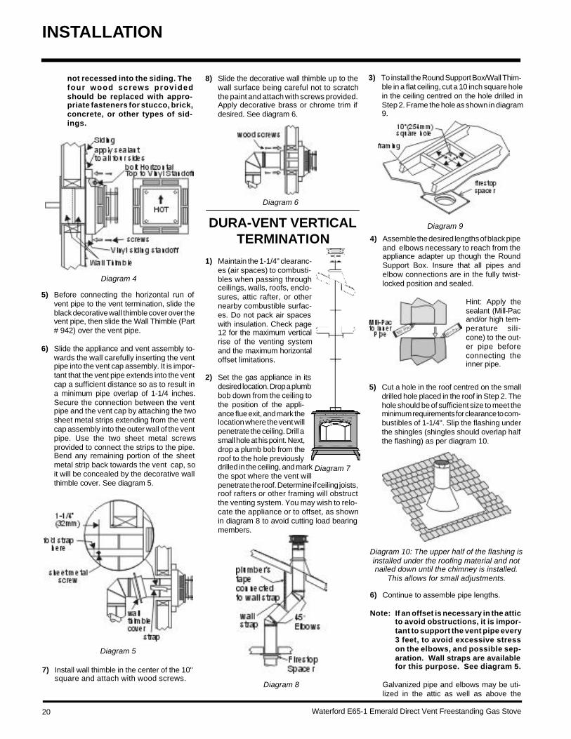
4) If installing the vent termination to a wall withvinyl siding, the Vinyl Siding Standoff mustbe used. Attach the Vinyl Siding Standoff tothe Horizontal Vent Termination, but firstrun a bead of non-hardening mastic aroundits outside edges, so as to make a sealbetween vent cap and the standoff. Installthe Vinyl Siding Standoff (Part # 950) be-tween the vent cap and the exterior walland attach with the four wood screwsprovided. Seal around the Vinyl SidingStandoff on all four sides. Diagram 6. Thearrow on the vent cap should be point-ing up. Insure that the 1-1/4" clearances tocombustible materials are maintained. Seediagram 4.
Note: If installing termination on a sidingcovered wall, a vinyl siding stand-off or furring strips must be usedto ensure that the termination is
DURA-VENT HORIZONTAL INSTALLATIONS
Diagram 1:Hint: Apply silicone to female end.
Note:a) Twist-lock procedure: Four indenta-
tions, located on the female ends ofpipes and fittings, are designed to slidestraight onto the male ends of adjacentpipes and fittings, by orienting the fourpipe indentations so they match andslide in to the four entry slots on the maleends (diagram 1). Push the pipe sec-tions completely together, then twist-lock one section clockwise approxi-mately one-quarter turn, until the twosections are fully locked. The femalelocking lugs will not be visible from theoutside on the Black Pipe or fittings.They may be located by examining theinside of the female ends. Apply seal-ant "Mill-Pac" to inner pipe and high tempsilicone sealant to outer pipe on everytwist-lock joint.
*As specified in CGAB149 InstallationCode. Local codes orregulations may re-quire different clear-ances.
Diagram 2
Diagram 2a
Diagram 3
Snorkel Termination diagrams show the vent-ing arrangements for units converted to thelower Btu rating of 27,000 (NG) or 29,000 (LP).
1) Set the unit in its desired location. Check todetermine if wall studs or roof rafters arein the way when the venting system isattached. If this is the case, you may wantto adjust the location of the unit.
2) Direct Vent pipe and fittings are designedwith special twist-lock connections to con-nect the venting system to the applianceflue outlet. A twist-lock appliance adapteris installed on the unit at the factory. As-semble the desired combina-tion of pipe and elbows to theappliance adapter with pipeseams oriented towardsthe wall or ceiling, asmuch out of view as pos-sible. The final position-ing of the pipe and 90o
elbow assembly is de-termined by the mount-ing orienta-tion of theadapter onthe stoveand twist-locked for asolid con-nection.
b) Horizontal runs of vent must be sup-ported every three feet. Wall straps areavailable for this purpose.
c) Snorkel Terminations:For installations requiring a vertical riseon the exterior of the building, 14-inchand 36-inch tall Snorkel Terminationsand the Riser Vent as shown in Dia. 2& 2a are available. Follow the sameinstallation procedures as used forstandard Horizontal Termination. NEV-ER install the snorkel upside down.
Below Grade Snorkel InstallationIf the Snorkel Termination must be installedbelow grade, i.e. basement application,proper drainage must be provided to pre-vent water from entering the Snorkel Ter-mination. Refer to Dura-Vent Installationinstructions for details. Do not attempt toenclose the Snorkel within the wall, or anyother type of enclosure.
3) With the pipe attached to the stove, slidethe stove into its correct location, and markthe wall for a 10" x 10" (inside dimensions)square hole. The center of the square holeshould line up with the centerline of the
horizontal pipe, as shown in diagram 3. Cutand frame the 10 inch square hole in theexterior wall where the vent will be termi-nated. If the wall being penetrated is con-structed of non- combustible material, i.e.masonry block orconcrete, a 7" di-ameter hole isacceptable.
INSTALLATION
20 Waterford E65-1 Emerald Direct Vent Freestanding Gas Stove
Diagram 9DURA-VENT VERTICALTERMINATION
Diagram 7
Diagram 8
3) To install the Round Support Box/Wall Thim-ble in a flat ceiling, cut a 10 inch square holein the ceiling centred on the hole drilled inStep 2. Frame the hole as shown in diagram9.
Hint: Apply thesealant (Mill-Pacand/or high tem-perature sili-cone) to the out-er pipe beforeconnecting theinner pipe.
Diagram 6
Diagram 5
Diagram 4
not recessed into the siding. Thefour wood screws providedshould be replaced with appro-priate fasteners for stucco, brick,concrete, or other types of sid-ings.
5) Before connecting the horizontal run ofvent pipe to the vent termination, slide theblack decorative wall thimble cover over thevent pipe, then slide the Wall Thimble (Part# 942) over the vent pipe.
6) Slide the appliance and vent assembly to-wards the wall carefully inserting the ventpipe into the vent cap assembly. It is impor-tant that the vent pipe extends into the ventcap a sufficient distance so as to result ina minimum pipe overlap of 1-1/4 inches.Secure the connection between the ventpipe and the vent cap by attaching the twosheet metal strips extending from the ventcap assembly into the outer wall of the ventpipe. Use the two sheet metal screwsprovided to connect the strips to the pipe.Bend any remaining portion of the sheetmetal strip back towards the vent cap, soit will be concealed by the decorative wallthimble cover. See diagram 5.
7) Install wall thimble in the center of the 10"square and attach with wood screws.
INSTALLATION
8) Slide the decorative wall thimble up to thewall surface being careful not to scratchthe paint and attach with screws provided.Apply decorative brass or chrome trim ifdesired. See diagram 6.
1) Maintain the 1-1/4" clearanc-es (air spaces) to combusti-bles when passing throughceilings, walls, roofs, enclo-sures, attic rafter, or othernearby combustible surfac-es. Do not pack air spaceswith insulation. Check page12 for the maximum verticalrise of the venting systemand the maximum horizontaloffset limitations.
2) Set the gas appliance in itsdesired location. Drop a plumbbob down from the ceiling tothe position of the appli-ance flue exit, and mark thelocation where the vent willpenetrate the ceiling. Drill asmall hole at his point. Next,drop a plumb bob from theroof to the hole previouslydrilled in the ceiling, and markthe spot where the vent willpenetrate the roof. Determine if ceiling joists,roof rafters or other framing will obstructthe venting system. You may wish to relo-cate the appliance or to offset, as shownin diagram 8 to avoid cutting load bearingmembers.
4) Assemble the desired lengths of black pipeand elbows necessary to reach from theappliance adapter up though the RoundSupport Box. Insure that all pipes andelbow connections are in the fully twist-locked position and sealed.
5) Cut a hole in the roof centred on the smalldrilled hole placed in the roof in Step 2. Thehole should be of sufficient size to meet theminimum requirements for clearance to com-bustibles of 1-1/4". Slip the flashing underthe shingles (shingles should overlap halfthe flashing) as per diagram 10.
Diagram 10: The upper half of the flashing isinstalled under the roofing material and notnailed down until the chimney is installed.
This allows for small adjustments.
6) Continue to assemble pipe lengths.
Note: If an offset is necessary in the atticto avoid obstructions, it is impor-tant to support the vent pipe every3 feet, to avoid excessive stresson the elbows, and possible sep-aration. Wall straps are availablefor this purpose. See diagram 5.
Galvanized pipe and elbows may be uti-lized in the attic as well as above the

Waterford E65-1 Emerald Direct Vent Freestanding Gas Stove 21
CATHEDRAL CEILINGS
Round Support (RDS) &Square Support (SQS)
If your home has a cathedral ceiling (no atticspace between the ceiling and the roof), installthe chimney and support as follows.
1) Situate the chimney in a convenient loca-tion as near as possible to the applianceoutlet. Cut and frame a hole in the roof forthe support. The sides of this hole must bevertical with 1 1/4" clearance.
2) Place the support in the opening. Lower itto the correct height as determined by thetable and diagram below.
Offset Chart
Diagram 12
7) Ensure vent is vertical and secure the baseof the flashing to the roof with roofing rails,slide storm collar over the pipe section andseal with a mastic.
8) Install the vertical termination cap by twistlocking it.
Notes:a) For multistorey vertical installations, a
Ceiling Fire stop (Part # 963) is requiredat the second floor, and any subse-quent floor. Diagram 12. The openingshould be framed to 10 " x 10" insidedimensions, in the same manner asshown in diagram 9.
b) Any occupied areas above the firstfloor, including closets and storagespaces, through which the verticalvent passes, must be enclosed.
Using a level, make sure the support isvertical. If the support extends above theroof, cut it flush with the top of the roof.Nail the support to the frame openingusing (8) 3" spiral nails or #8 x 1-1/2"screws.
Note: If you are using a 6" square sup-port you may find it difficult toscrew it in place because it is fairlysmall inside.
Simpson Dura-Vent has provided anglebrackets with this support which can bescrewed to the outside of the support boxand nailed to surrounding framing as re-quired. Use a minimum of four #8 x 1/2"screws per bracket. In some cases thesebrackets may need to be trimmed (e.g.: tofit under a flashing). Place the FinishCollar around the support and fasten it tothe ceiling using the screws provided.
3) Use appropriate roof flashing. Place theflashing under the upper shingles and ontop of the lower shingles approximatelyhalf of the flashing should be under theshingles.
4) Assemble the desired lengths of Black Pipeand Elbows necessary to reach from theappliance adapter up through the supportbox and flashing to proper height as perDia. 12, local codes or pages 12 to 13.Ensure that all pipe and elbow connectionsare in their fully twist lock position.
5) Ensure vent is vertical and secure flashingto the roof with roofing nails. Slide thestorm collar over the pipe section and sealwith a mastic.
6) Twist lock the vent cap on to the lastsection.
INSTALLATION
Diagram 11
roofline. The galvanized finish is desirableabove the roofline due to its higher corro-sion resistance.
Continue to add pipe sections through theflashing until the height of the vent capmeets the minimum height requirementsspecified in diagram 11 or local codes. Notethat for steep roof pitches, the verticalheight must be increased. A poor draft, ordown drafting can result from high windconditions near big trees or adjoining rooflines, in these cases, increasing the ventheight may solve the problem.
Slope "X"
0/12 - 2/12 4"
2/12 - 7/12 5-1/2"
7/12 - 12/12 6-3/4"
12/12 - 24/12 7-1/2"
24/12+ 12-1/2"
Roof Pitch Minimum Vent Height
Feet Metersflat to 7/12 2 0.61over 7/12 to 8/12 2 0.61over 8/12 to 9/12 2 0.61over 9/12 to 10/12 2.5 0.76over 10/12 to 11/12 3.25 0.99over 11/12 to 12/12 4 1.22over 12/12 to 14/12 5 1.52over 14/12 to 16/12 6 1.83over 16/12 to 18/12 7 2.13over 18/12 to 20/12 7.5 2.29over 20/12 to 21/12 8 2.44
22 Waterford E65-1 Emerald Direct Vent Freestanding Gas Stove
INSTALLATION
Diagram 3
Diagram 4
Diagram 5
4) Pass the flex pipe down through the centerof the chimney system, and center theadaptor on the top of the chimney pipe. Drillfour 1/8" diameter holes through the adap-tor and into the chimney top. Insure that youare in fact, drilling into the metal on thechimney. Twist-lockthe Termination Cap(Part# 980 or 991) ontothe Adaptor. (Diagram3 and 4).
5) Pull the flex pipe down through the ceilingsupport box, until it protrudes approximate-ly 3" (76mm). Connect the flex pipe to theRetro Connector by slipping it into the4-3/4" diameter sleeve on the top side of theConnector. Use 3 sheet metal screws toassemble these two parts.
6) Push the flex pipe back up into the ceilingsupport box, center the Retro Connector,and attach it to the support box, or decora-tive sleeve for double wall solid packedpipe, with the sheet metal screws (sup-plied). The holes in the Retro Connector arepre-punched. Diagram 5.
Support Extensions - Round(RDSE) or Square (SQSE)
Steep pitched cathedral ceilings may require theuse of a support extension. This piece fits downinside the support and can be adjusted toincrease the support's length by up to 22". Theextension is attached to the support using theeight metal screws provided. Be sure there isat least a 2 inch overlap where the extensionjoins the support.
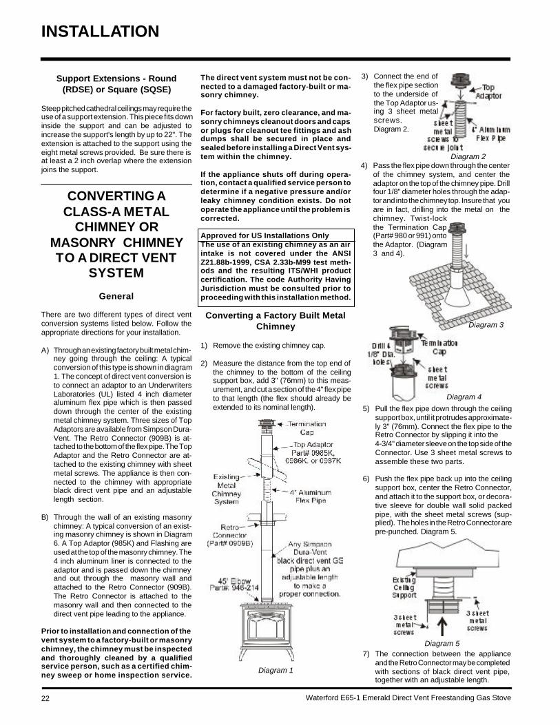
CONVERTING ACLASS-A METAL
CHIMNEY ORMASONRY CHIMNEYTO A DIRECT VENT
SYSTEM
General
There are two different types of direct ventconversion systems listed below. Follow theappropriate directions for your installation.
A) Through an existing factory built metal chim-ney going through the ceiling: A typicalconversion of this type is shown in diagram1. The concept of direct vent conversion isto connect an adaptor to an UnderwritersLaboratories (UL) listed 4 inch diameteraluminum flex pipe which is then passeddown through the center of the existingmetal chimney system. Three sizes of TopAdaptors are available from Simpson Dura-Vent. The Retro Connector (909B) is at-tached to the bottom of the flex pipe. The TopAdaptor and the Retro Connector are at-tached to the existing chimney with sheetmetal screws. The appliance is then con-nected to the chimney with appropriateblack direct vent pipe and an adjustablelength section.
B) Through the wall of an existing masonrychimney: A typical conversion of an exist-ing masonry chimney is shown in Diagram6. A Top Adaptor (985K) and Flashing areused at the top of the masonry chimney. The4 inch aluminum liner is connected to theadaptor and is passed down the chimneyand out through the masonry wall andattached to the Retro Connector (909B).The Retro Connector is attached to themasonry wall and then connected to thedirect vent pipe leading to the appliance.
Prior to installation and connection of thevent system to a factory-built or masonrychimney, the chimney must be inspectedand thoroughly cleaned by a qualifiedservice person, such as a certified chim-ney sweep or home inspection service.
3) Connect the end ofthe flex pipe sectionto the underside ofthe Top Adaptor us-ing 3 sheet metalscrews.Diagram 2.
Diagram 1
Diagram 2
The direct vent system must not be con-nected to a damaged factory-built or ma-sonry chimney.
For factory built, zero clearance, and ma-sonry chimneys cleanout doors and capsor plugs for cleanout tee fittings and ashdumps shall be secured in place andsealed before installing a Direct Vent sys-tem within the chimney.
If the appliance shuts off during opera-tion, contact a qualified service person todetermine if a negative pressure and/orleaky chimney condition exists. Do notoperate the appliance until the problem iscorrected.
Approved for US Installations OnlyThe use of an existing chimney as an airintake is not covered under the ANSIZ21.88b-1999, CSA 2.33b-M99 test meth-ods and the resulting ITS/WHI productcertification. The code Authority HavingJurisdiction must be consulted prior toproceeding with this installation method.
Converting a Factory Built MetalChimney
1) Remove the existing chimney cap.
2) Measure the distance from the top end ofthe chimney to the bottom of the ceilingsupport box, add 3" (76mm) to this meas-urement, and cut a section of the 4" flex pipeto that length (the flex should already beextended to its nominal length).
7) The connection between the applianceand the Retro Connector may be completedwith sections of black direct vent pipe,together with an adjustable length.
Waterford E65-1 Emerald Direct Vent Freestanding Gas Stove 23
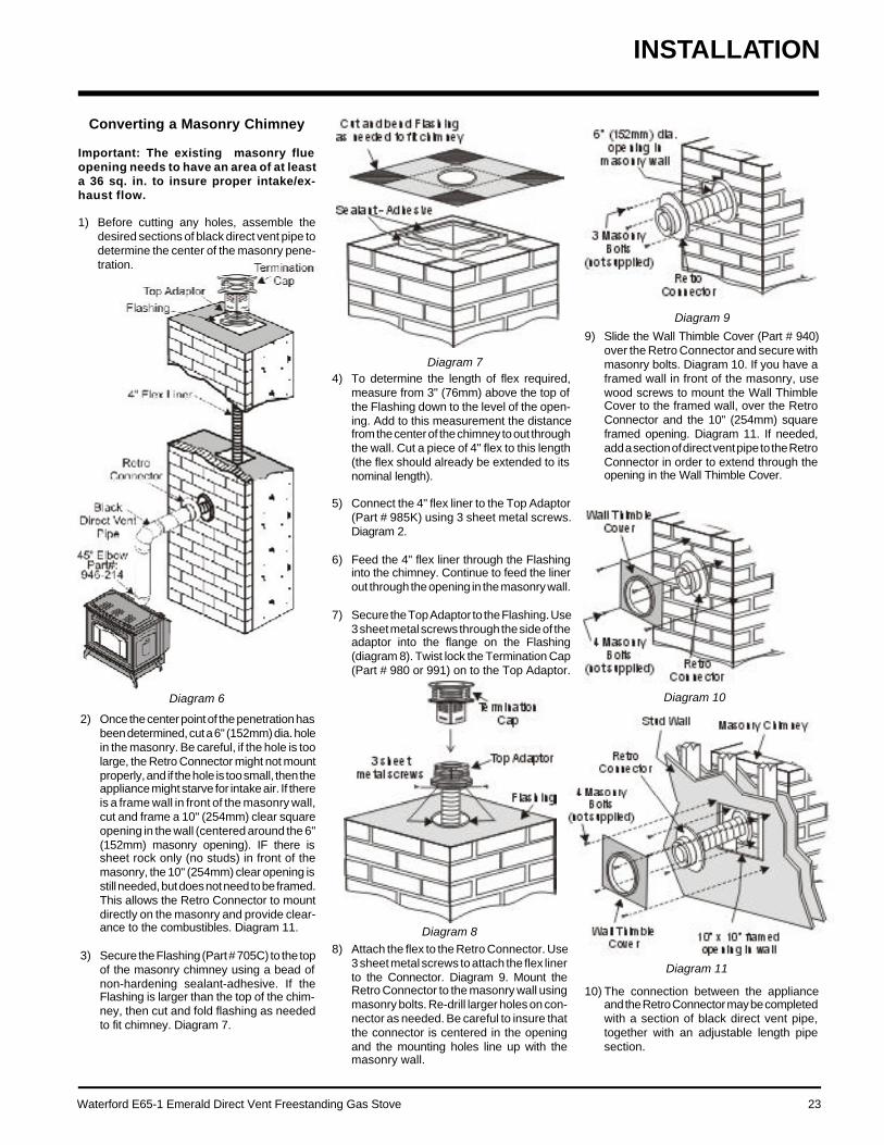
Converting a Masonry Chimney
Important: The existing masonry flueopening needs to have an area of at leasta 36 sq. in. to insure proper intake/ex-haust flow.
1) Before cutting any holes, assemble thedesired sections of black direct vent pipe todetermine the center of the masonry pene-tration.
Diagram 6
2) Once the center point of the penetration hasbeen determined, cut a 6" (152mm) dia. holein the masonry. Be careful, if the hole is toolarge, the Retro Connector might not mountproperly, and if the hole is too small, then theappliance might starve for intake air. If thereis a frame wall in front of the masonry wall,cut and frame a 10" (254mm) clear squareopening in the wall (centered around the 6"(152mm) masonry opening). IF there issheet rock only (no studs) in front of themasonry, the 10" (254mm) clear opening isstill needed, but does not need to be framed.This allows the Retro Connector to mountdirectly on the masonry and provide clear-ance to the combustibles. Diagram 11.
3) Secure the Flashing (Part # 705C) to the topof the masonry chimney using a bead ofnon-hardening sealant-adhesive. If theFlashing is larger than the top of the chim-ney, then cut and fold flashing as neededto fit chimney. Diagram 7.
Diagram 74) To determine the length of flex required,
measure from 3" (76mm) above the top ofthe Flashing down to the level of the open-ing. Add to this measurement the distancefrom the center of the chimney to out throughthe wall. Cut a piece of 4" flex to this length(the flex should already be extended to itsnominal length).
5) Connect the 4" flex liner to the Top Adaptor(Part # 985K) using 3 sheet metal screws.Diagram 2.
6) Feed the 4" flex liner through the Flashinginto the chimney. Continue to feed the linerout through the opening in the masonry wall.
7) Secure the Top Adaptor to the Flashing. Use3 sheet metal screws through the side of theadaptor into the flange on the Flashing(diagram 8). Twist lock the Termination Cap(Part # 980 or 991) on to the Top Adaptor.
Diagram 88) Attach the flex to the Retro Connector. Use
3 sheet metal screws to attach the flex linerto the Connector. Diagram 9. Mount theRetro Connector to the masonry wall usingmasonry bolts. Re-drill larger holes on con-nector as needed. Be careful to insure thatthe connector is centered in the openingand the mounting holes line up with themasonry wall.
Diagram 9
9) Slide the Wall Thimble Cover (Part # 940)over the Retro Connector and secure withmasonry bolts. Diagram 10. If you have aframed wall in front of the masonry, usewood screws to mount the Wall ThimbleCover to the framed wall, over the RetroConnector and the 10" (254mm) squareframed opening. Diagram 11. If needed,add a section of direct vent pipe to the RetroConnector in order to extend through theopening in the Wall Thimble Cover.
Diagram 10
Diagram 11
10) The connection between the applianceand the Retro Connector may be completedwith a section of black direct vent pipe,together with an adjustable length pipesection.
INSTALLATION

24 Waterford E65-1 Emerald Direct Vent Freestanding Gas Stove
AERATIONADJUSTMENT
The burner aeration is factory set but may needadjusting due to either the local gas supply, airsupply or altitude.
HIGH ELEVATION
This unit (with 38,000 Btu) is approved in Can-ada for altitude 2000 ft. to 4500 ft. (CAN/CGA-2.17-M91) with the orifice kit Part # 621-975. ForNatural Gas installations above 4500 ft. followcurrent CAN/CGA-B149.1. In U.S.A., for installa-tions above 2000 ft. refer to current ANSI Z223.1Sc8-8.1.2a appendix F, for resizing orifice.
INSTALLATION
The aeration adjustment gears are located onthe right side of theburner box and canbe accessed fromthe side.
To adjust the aera-tion: use the allenkey to turn the turn-ing gear which will adjust the air shutter. Openthe air shutter for a blue flame or close it for ayellower flame. The factory setting should besufficient for most installations.
Note: Prior to any pressure testing ofthe gas supply piping system thatexceeds test pressures of 1/2psig, this appliance must be dis-connected from the piping sys-tem. If test pressures equal to orless than 1/2 psig are used thenthis appliance must be isolatedfrom the piping system by closingits individual manual shut-off valveduring the testing.
Caution: Carbon will be produced if theair shutter is closed too much.
Note: Any damage due to carboning re-sulting from improperly settingthe aeration controls is NOT cov-ered under warranty.
Note: Aeration Adjustment should onlybe performed by an authorizedRegency Installer at the time ofinstallation or service.
GAS CONNECTION
The gas connection is a 3/8" NPT 90o elbow.The gas line can be rigid pipe or to makeinstallation easier, use a listed flexible connec-tor and/or copper tubing if allowed by localcodes. Since some municipalities have addi-tional local codes it is always best to consultwith your local authorities and the CAN/CGAB149 installation codes.
For USA installations follow local codes and/or the current National Fuel Gas Code, ANSIZ223.1.
When using copper or flex connectors useonly approved fittings. Always provide a unionso that gas lines can be easily disconnectedfor burner and/or valve servicing. Flare nutsfor copper lines and flex connectors are usu-ally considered to meet this requirement.
IMPORTANT: ALWAYS CHECK FORGAS LEAKS WITH A SOAP ANDWATER SOLUTION OR GAS LEAKDETECTOR. DO NOT USE OPENFLAME FOR LEAK TESTING.
Clockwise to open,counter-clockwise to close.
SYSTEM DATA - E65-1(WITH 38,000 BTU)
For 0 to 2000* feet altitudeBurner Inlet Orifice Sizes:
Natural Gas PropaneBurner #32 #50
*Above 2000 ft. see National Fuel CodeOrifice Chart.
Max. Input Rating- Natural Gas 38,000 Btu/h- Propane 38,000 Btu/h
Min. Input Rating- Natural Gas 19,000 Btu/h - Propane 19,000 Btu/h
Output Capacity with blower Off*Natural Gas 29,070 Btu/hPropane 29,650 Btu/h
Output Capacity with blower On*Natural Gas 29,564 Btu/hPropane 30,172 Btu/h
*See page 8 for manufactured home chart.
Supply PressureNatural Gas min. 5.0" w.c.Propane min. 12.0" w.c.
Manifold PressureNatural Gas 3.8" +/- 0.2" w.c.Propane 11" +/- 0.2" w.c.
SYSTEM DATAHIGH ELEVATION: E65-NG1
For 2,000 - 4,500 feet altitudeBurner Inlet Orifice Sizes:
Natural GasBurner #33
Max. Input Rating- Natural Gas 36,100 Btu/h
Min. Input Rating- Natural Gas 18,000 Btu/h
Output Capacity with blower OffNatural Gas 27,616 Btu/h
Max. Output Capacity with blower OnNatural Gas 28,086 Btu/h
SYSTEM DATA -E65-1 CONVERTED TO27,000 (NATURAL GAS)OR 29,000 (PROPANE)
For 0 to 4500 feet altitudeBurner Inlet Orifice Sizes:
Natural Gas PropaneBurner #40 #52
Max. Input Rating- Natural Gas 27,000 Btu/h - Propane 29,000 Btu/h
Min. Input Rating- Natural Gas 13,500 Btu/h- Propane 14,500 Btu/h
Output Capacity with blower Off*Natural Gas 19,845 Btu/hPropane 22,040 Btu/h
Output Capacity with blower On*Natural Gas 20,385 Btu/hPropane 22,765 Btu/h
*See page 8 for manufactured home chart.
Supply PressureNatural Gas min. 5.0" w.c.Propane min. 12.0" w.c.
Manifold PressureNatural Gas 3.8" +/- 0.2" w.c.Propane 11" +/- 0.2" w.c.
with 38,000 Btu with 27,000 (NG) / 29,000 LP
Natural Gas Natural Gas
3/8"(9.5mm) 3/16"(4.75mm)
Propane Propane
wide open 1/4" (6.35mm)

Waterford E65-1 Emerald Direct Vent Freestanding Gas Stove 25
4) Carefully remove the logs, embers androckwool.
5) Remove burner. See diagram below.
Pilot assembly is now accessiblefor steps 6) to 11).
Note: Use a magnetic type screwdriverif possible.
THIS CONVERSION MUSTBE DONE BY A
QUALIFIED GASFITTER IF IN DOUBT DO
NOT DO THISCONVERSION !!
3) Open the front door. Open the right sidedoor and there is a cutout in the heat shieldthrough which can be seen a wing nutthreaded on to a stud attached to the frontdoor. Loosen this nut by turning it counter-clockwise.
Conversion Kit Contains:
Qty. Part # Description1 910-018 SIT Conversion Kit-50%
Turndown LP1 910-037 LP Injector (Pilot Orifice)1 904-641 Burner Orifice #501 908-175 E63/E65 Decal "Converted to
Propane"1 908-528 Red "PROPANE" label1 908-780 Instruction Sheet
1) Shut off the gas supply.
2) Open the valve door and remove the controlpanel.
CONVERSION KITFROM NATURAL GAS
TO PROPANEModel #261-969
for Emerald Gas Stoves and GasInserts using SIT 820 NOVA Gas
Valve
INSTALLATION
GAS PIPEPRESSURE TESTING
The appliance must be isolated from the gassupply piping system by closing its individualmanual shut-off valve during any pressuretesting of the gas supply piping system at testpressures equal to or less than 1/2 psig. (3.45kPa). Disconnect piping from valve at pressuresover 1/2 psig.
The manifold pressure is controlled by a regu-lator built into the gas control, and should bechecked at the pressure test point.
Note: To properly check gas pressure,both inlet and manifold pressuresshould be checked using the valvepressure ports on the valve.
1) Make sure the valve is in the "OFF" position.
2) Loosen the "IN" and/or "OUT" pressure tap(s),turning counterclockwise with a 1/8" wideflat screwdriver.
3) Attach manometer to "IN" and/or "OUT" pres-sure tap(s) using a 5/16" ID hose.
4) Light the pilot and turn the valve to "ON"position. Read manometer.
5) The pressure check should be carried outwith the unit burning and the setting shouldbe within the limits specified on the safetylabel.
6) When finished reading manometer, turn offthe gas valve, disconnect the hose andtighten the screw (clockwise) with a 1/8"flat screwdriver. Note: Screw should besnug, but do not over tighten
Valve Description
1) Gas cock knob2) Manual high/low adjustment3) Pilot Adjustment4) Thermocouple Connection5) Main Operator6) Outlet Pressure Tap (Manifold Pressure)7) Inlet Pressure Tap (Supply Pressure)8) Pilot Outlet9) Main Gas Outlet10) Flange Securing Screw Holes11) Alternative TC Connection Point12) Thermoelectric Unit13) Additional Valve Mounting Hole

26 Waterford E65-1 Emerald Direct Vent Freestanding Gas Stove
REDUCTION KIT TOLOWER BTU RATING
FOR E65-1 GAS STOVE
3) Open the front door. Open the right sidedoor and there is a cutout in the heat shieldthrough which can be seen a wing nutthreaded on to a stud attached to the frontdoor. Loosen this nut by turning it counter-clockwise.
Natural Gas Conversion Kit 260-920Contains:Qty.Part # Description1 904-593 Burner Orifice #40
(Natural Gas)1 908-365 Decal "Converted to
27,000 Btu"1 908-363 Instruction Sheet
Propane Conversion Kit 260-922Contains:Qty.Part # Description1 904-390 Burner Orifice #52 (Propane)1 908-365 Decal "Converted to
29,000 Btu"1 908-363 Instruction Sheet
1) Shut off the gas supply.
2) Open the valve door and remove the con-trol panel.
The wing nut that holds the front door isaccessible through the cut-out in the right
side heat shield.
E63/E65 Conversion Decal: 908-175
Burner Orifice
9) Unscrew the pilot orifice with the allen keyand replace with the LP pilot orifice in the kit.
INSTALLATION
6) Remove and discard the 3 pressure regu-lator mounting screws (A), pressure reg-ulator tower (B) and diaphragm (C).
7) Insure that the rubber gasket (D) is properlypositioned and install the new HI/LO pres-sure regulator assembly to the valve usingthe new screws (E) supplied with the kit.Tighten screws securely.
8) Pull off the pilot cap to expose the pilotorifice.
10) Remove burner orifice with a 1/2" wrenchand discard. Use a wrench to hold on to theelbow behind the orifice.
11) Reinstall new burner orifice LP stamped#50 and tighten.
12) Reverse steps 4) to 2).
13) Attach the Conversion label "This unit hasbeen converted to Propane" on top of theSerial # decal. E63/E65: Part #175
14) Replace yellow "Natural Gas" label with red"Propane" label
15) Check for gas leaks.
16) Check inlet and outlet pressures.
17) Check operation of flame control.
18) Check for proper flame appearance andglow on logs.
THIS CONVERSION MUSTBE DONE BY A
QUALIFIED GAS FITTER IFIN DOUBT DO NOT DOTHIS CONVERSION !!
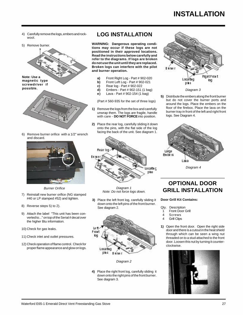
Waterford E65-1 Emerald Direct Vent Freestanding Gas Stove 27
OPTIONAL DOORGRILL INSTALLATION
Door Grill Kit Contains:
Qty. Description1 Front Door Grill4 Screws4 Grill Clips
1) Open the front door. Open the right sidedoor and there is a cutout in the heat shieldthrough which can be seen a wing nutthreaded on to a stud attached to the frontdoor. Loosen this nut by turning it counter-clockwise.
5) Distribute the embers along the front burnerbut do not cover the burner ports andaround the logs. Place the embers on thefloor of the firebox. Place the lava on theburner tray in front of the left and right frontlogs. See Diagram 4.
Diagram 4
Diagram 3
Diagram 1Note: Do not force logs down.
Diagram 2
3) Place the left front log, carefully sliding itdown onto the left pins of the front burner.See diagram 2.
LOG INSTALLATION
WARNING: Dangerous operating condi-tions may occur if these logs are notpositioned in their approved locations.Read the instructions below carefully andrefer to the diagrams. If logs are brokendo not use the unit until they are replaced.Broken logs can interfere with the pilotand burner operation.
a) Front Right Log - Part # 902-020b) Front Left Log - Part # 902-021c) Rear log - Part # 902-022d) Embers - Part # 902-151 (1 bag)e) Lava - Part # 902-154 (1 bag)
(Part # 560-935 for the set of three logs)
1) Remove the logs from the box and carefullyunwrap them. The logs are fragile, handlewith care - DO NOT FORCE into position.
2) Place the rear log, carefully sliding it downonto the pins, with the flat side of the logfacing the back of the unit. See diagram 1.
4) Carefully remove the logs, embers and rock-wool.
5) Remove burner.
Burner Orifice
INSTALLATION
Note: Use amagnetic typescrewdriver ifpossible.
6) Remove burner orifice with a 1/2" wrenchand discard.
7) Reinstall new burner orifice (NG stamped#40 or LP stamped #52) and tighten.
8) Reverse steps 5) to 2).
9) Attach the label "This unit has been con-verted to..." on top of the Serial # decal overthe higher Btu information.
10) Check for gas leaks.
11) Check inlet and outlet pressures.
12) Check operation of flame control. Check forproper flame appearance and glow on logs.
4) Place the right front log, carefully sliding itdown onto the right pins of the front burner.See diagram 3.

28 Waterford E65-1 Emerald Direct Vent Freestanding Gas Stove
OPTIONAL WALLTHERMOSTAT
A wall thermostat may be installed if desired.Connect the wires as per the wiring diagrams.Note that the wires are connected to the "TH"on the gas valve. Use table below to determinethe maximum wire length:
Note: Preferable if the thermostat is in-stalled on an interior wall.
Waterford offers an optional programmablethermostat but any 250-750 millivolt rated non-anticipator type thermostat that is CSA, ULC orUL approved may be used.
CAUTIONDo not connect the millivolt
wall thermostat wiresto the 120V wires.
INSTALLATION
2) Remove the glass panel by loosening the 6screws securing the glass brackets. Sup-port the glass to prevent it from droppingout and breaking.
3) Attach the 4 grill clips with the 4 screws butdo not tighten down at this point.
4) Place the grill into position on the front of thedoor, center it in the front viewing area anduse the grill clips to hold it in place.
5) Tighten the screws on the grill clips.
6) Replace the glass and secure the glassclips, reversing step 2)
7) Close the front door by reversing step 1).
Thermostat Wire Table
OPTIONAL REMOTECONTROL
Use the Waterford Remote Control Kit approvedfor this unit. Use of other systems may void yourwarranty.
The remote control kit comes with a hand heldtransmitter, a receiver and a wall mountingplate.
1) Choose a convenient location on the wall toinstall the receiver and the receptacle box(protection from extreme heat is very impor-tant). Run wires from the fireplace to thatlocation, use Thermostat Wire Table.
2) Connect the wires as per the wiring dia-gram below.
FINAL CHECK
Before leaving this unit with the customer, theinstaller must ensure that the appliance is firingcorrectly. This includes:
1) Clocking the appliance to ensure the cor-rect firing rate (rate noted on label) at 15minutes.
2) If required, adjusting the primary air toensure that the flame does not carbon. Firstallow the unit to burn for 15 min. to stabilize.
3) Check for proper draft.
CAUTION
Any alteration to the product that causessooting or carboning that results in dam-age to the exterior facia is not the respon-sibility of the manufacturer.
CAUTIONDo not connect the
millivolt remote control wiresto the 120V wires.
3) Install 3 AAA alkaline batteries in transmitterand 4 AA alkaline batteries in the receiver.Install the receiver and its cover in the wall.Switch the remote receiver to "remote"mode. The remote control is now ready foroperation.
14 GA.16 GA.18 GA.20 GA.22 GA.
50 Ft.32 Ft.20 Ft.12 Ft.9 Ft.
Recommended Maximum Lead Length(Two-Wire) When Using WallThermostat (CP-2 System)
Wire Size Max. Length
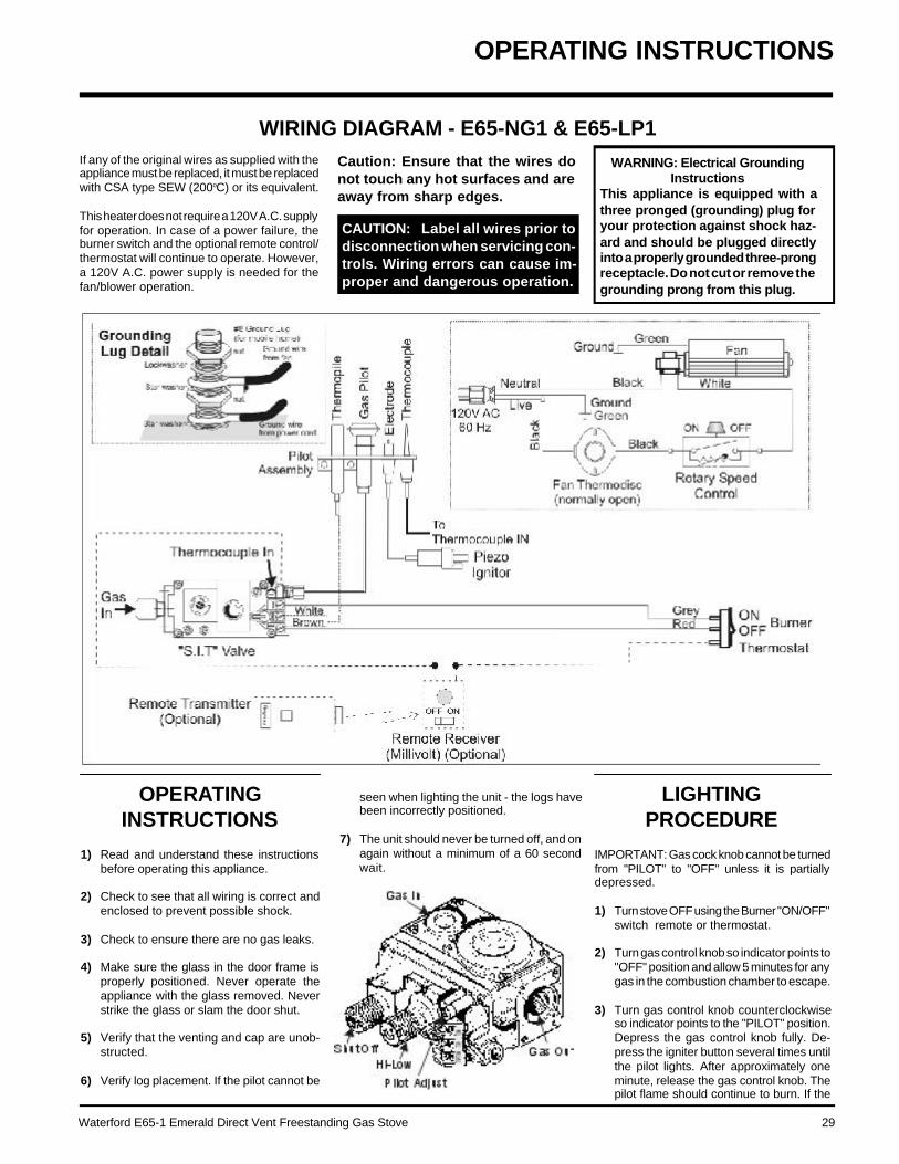
Waterford E65-1 Emerald Direct Vent Freestanding Gas Stove 29
OPERATINGINSTRUCTIONS
1) Read and understand these instructionsbefore operating this appliance.
2) Check to see that all wiring is correct andenclosed to prevent possible shock.
3) Check to ensure there are no gas leaks.
4) Make sure the glass in the door frame isproperly positioned. Never operate theappliance with the glass removed. Neverstrike the glass or slam the door shut.
5) Verify that the venting and cap are unob-structed.
6) Verify log placement. If the pilot cannot be
WIRING DIAGRAM - E65-NG1 & E65-LP1If any of the original wires as supplied with theappliance must be replaced, it must be replacedwith CSA type SEW (200oC) or its equivalent.
This heater does not require a 120V A.C. supplyfor operation. In case of a power failure, theburner switch and the optional remote control/thermostat will continue to operate. However,a 120V A.C. power supply is needed for thefan/blower operation.
Caution: Ensure that the wires donot touch any hot surfaces and areaway from sharp edges.
seen when lighting the unit - the logs havebeen incorrectly positioned.
7) The unit should never be turned off, and onagain without a minimum of a 60 secondwait.
LIGHTINGPROCEDURE
IMPORTANT: Gas cock knob cannot be turnedfrom "PILOT" to "OFF" unless it is partiallydepressed.
1) Turn stove OFF using the Burner "ON/OFF"switch remote or thermostat.
2) Turn gas control knob so indicator points to"OFF" position and allow 5 minutes for anygas in the combustion chamber to escape.
3) Turn gas control knob counterclockwiseso indicator points to the "PILOT" position.Depress the gas control knob fully. De-press the igniter button several times untilthe pilot lights. After approximately oneminute, release the gas control knob. Thepilot flame should continue to burn. If the
OPERATING INSTRUCTIONS
WARNING: Electrical GroundingInstructions
This appliance is equipped with athree pronged (grounding) plug foryour protection against shock haz-ard and should be plugged directlyinto a properly grounded three-prongreceptacle. Do not cut or remove thegrounding prong from this plug.
CAUTION: Label all wires prior todisconnection when servicing con-trols. Wiring errors can cause im-proper and dangerous operation.

30 Waterford E65-1 Emerald Direct Vent Freestanding Gas Stove
Copy of the Lighting Plate instructions
OPERATING INSTRUCTIONS
pilot does not remain lit, repeat operationallowing a longer period before releasinggas control knob.
4) When the pilot stays lit, turn the gas knobfurther counterclockwise to the "ON" posi-tion.
5) Use the thermostat or remote control to turnon the unit.
6) Rotate the flame height regulator to adjustthe flame height higher or lower.
SHUTDOWNPROCEDURE
1) Use the thermostat or remote control to turnoff the main burner.
2) Turn the main gas control clockwise to the"OFF" position to turn off the pilot (pushknob in slightly).
3) Turn off all electric power to appliance ifservice is to be performed.
FIRST FIRE
The FIRST FIRE in your stove is part of the paintcuring process. To ensure that the paint isproperly cured, it is recommended that you burnyour fireplace for at least four (4) hours the firsttime you use it with the fan on. When firstoperated, the unit will release an odour causedby the curing of the paint and the burning off ofany oils remaining from manufacturing. Smokedetectors in the house may go off at this time.Open a few windows to ventilate the room fora couple of hours. The glass may requirecleaning.
DO NOT ATTEMPT TO CLEAN THE GLASSWHILE IT IS STILL HOT!
Note: When the glass is cold and theappliance is lit, it may cause con-densation and fog the glass. Thiscondensation is normal and willdisappear in a few minutes as theglass heats up.
During the first few fires, a white filmmay develop on the glass front as partof the curing process. The glass shouldbe cleaned or the film will bake on andbecome very difficult to remove. Use anon-abrasive cleaner and NEVER cleanthe glass while it is hot.
DO NOT BURN THE APPLIANCEWITHOUT THE GLASS FRONT INPLACE.

Waterford E65-1 Emerald Direct Vent Freestanding Gas Stove 31
8) Each time the appliance is lit, it may causecondensation and fog the glass. This con-densation and fog is normal and will disap-pear in a few minutes as the glass heats up.
Never operate the appliance withoutthe glass properly secured in place orwith the door open.
9) Periodically check the pilot flames. Correctflame pattern has three strong blue flames:1 flowing around the thermopile and 1around the thermocouple, and 1 flowing
6) The appliance and venting system must beinspected before use, and at least annual-ly, by a qualified field service person, toensure that the flow of combustion andventilation air is not obstructed.During the annual service call, the burnersshould be removed from the burner trayand cleaned. Replace the embers but do notblock the pilot.
7) Keep the area near the appliance clear andfree from combustible materials, gasoline,and other flammable vapours and liquids.
MAINTENANCEINSTRUCTIONS
1) Always turn off the valve before cleaning.For relighting, refer to lighting instructions.Keep the burner and control compartmentclean by brushing and vacuuming at leastonce a year. When cleaning the logs, use asoft clean paint brush as the logs are fragileand easily damaged.
2) Clean glass (never when unit is hot), appli-ance, and door with a damp cloth. Neveruse an abrasive cleaner.
3) The heater is finished in a porcelain finish orwith a heat resistant paint and should onlybe refinished with heat resistant paint (notwith wall paint). Waterford uses Stove-Bright Paint - Metallic Black #6309.
Never use an abrasive cleaner on the por-celain finish as it may scratch the surface.
4) Make a periodic check of burner for properposition and condition. Visually check theflame of the burner periodically, making surethe flames are steady; not lifting or floating.If there is a problem, call a qualified serviceperson.
5) Caution: Label all wires prior to disconnec-tion when servicing controls. Wiring errorscan cause improper and dangerous opera-tion.
AUTOMATICCONVECTION FAN
OPERATION
The fan operates automatically - turn the knobat the top right rear corner to adjust to thedesired speed. The fan will turn on as the stovecomes up to operating temperature. After theunit has been turned off and the unit cooled tobelow a useful heat output range the fan willshut off automatically.
ADJUSTING FLAMEHEIGHT
Your heater has an adjustable flame to tailor thelook and heat output to your specific needs. Itis adjusted by turning the flame adjustment dialon the gas control valve.
Turn clockwise to adjust the flame higher,counterclockwise for a lower flame.
NORMAL OPERATINGSOUNDS OF
GAS APPLIANCES
It is possible that you will hear some soundsfrom your gas appliance. This is perfectly nor-mal due to the fact that there are various gaugesand types of steel used within your appliance.Listed below are some examples. All are nor-mal operating sounds and should not beconsidered as defects in your appliance.
Blower:Waterford gas appliances use high tech blow-ers to push heated air farther into the room. It isnot unusual for the fan to make a "whirring"sound when ON. This sound will increase ordecrease in volume depending on the speedsetting of your fan speed control.
Burner Tray:The burner tray is positioned directly under theburner tube(s) and logs and is made of adifferent gauge material from the rest of thefirebox and body. Therefore, the varying thick-nesses of steel will expand and contract atslightly different rates which can cause "tick-ing" and "cracking" sounds. You should alsobe aware that as there are temperature chang-es within the unit these sounds will likely re-occur. Again, this is normal for steel fireboxes.
Blower Thermodisc:When this thermally activated switch turns ONit will create a small "clicking" sound. This is theswitch contacts closing and is normal.
Pilot Flame:While the pilot flame is on it can make a veryslight "whisper" sound.
Gas Control Valve:As the gas control valve turns ON and OFF, adull clicking sound may be audible, this isnormal operation of a gas regulator or valve.
Unit Body/Firebox:Different types and thicknesses of steel willexpand and contract at different rates result-ing in some "cracking" and "ticking" sounds willbe heard throughout the cycling process.
MAINTENANCE
CAUTION: ANY SAFETY SCREENOR GUARD REMOVED FOR SERV-ICING AN APPLIANCE MUST BEREPLACED PRIOR TO OPERAT-ING THE APPLIANCE.
CLOTHING OR OTHER FLAMMA-BLE MATERIAL SHOULD NOT BEPLACED ON OR NEAR THE AP-PLIANCE.
WARNING: CHILDREN ANDADULTS SHOULD BE ALERTEDTO THE HAZARDS OF HIGH SUR-FACE TEMPERATURE ANDSHOULD STAY AWAY TO AVOIDBURNS OR CLOTHING IGNITION.YOUNG CHILDREN SHOULD BECAREFULLY SUPERVISED WHENTHEY ARE IN THE SAME ROOMAS THE APPLIANCE.
DO NOT USE THIS APPLIANCE IFANY PART HAS BEEN UNDER WA-TER. IMMEDIATELY CALL AQUALIFIED SERVICE TECHNI-CIAN TO INSPECT THE APPLI-ANCE AND TO REPLACE ANYPART OF CONTROL SYSTEMAND ANY GAS CONTROL WHICHHAS BEEN UNDER WATER.
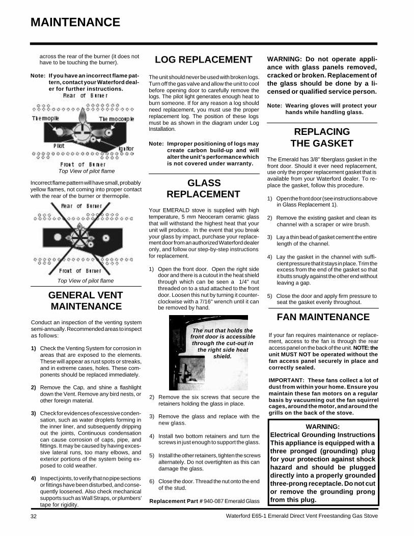
32 Waterford E65-1 Emerald Direct Vent Freestanding Gas Stove
FAN MAINTENANCE
If your fan requires maintenance or replace-ment, access to the fan is through the rearaccess panel on the back of the unit. NOTE: theunit MUST NOT be operated without thefan access panel securely in place andcorrectly sealed.
IMPORTANT: These fans collect a lot ofdust from within your home. Ensure youmaintain these fan motors on a regularbasis by vacuuming out the fan squirrelcages, around the motor, and around thegrills on the back of the stove.
GENERAL VENTMAINTENANCE
Conduct an inspection of the venting systemsemi-annually. Recommended areas to inspectas follows:
1) Check the Venting System for corrosion inareas that are exposed to the elements.These will appear as rust spots or streaks,and in extreme cases, holes. These com-ponents should be replaced immediately.
2) Remove the Cap, and shine a flashlightdown the Vent. Remove any bird nests, orother foreign material.
3) Check for evidences of excessive conden-sation, such as water droplets forming inthe inner liner, and subsequently drippingout the joints, Continuous condensationcan cause corrosion of caps, pipe, andfittings. It may be caused by having exces-sive lateral runs, too many elbows, andexterior portions of the system being ex-posed to cold weather.
4) Inspect joints, to verify that no pipe sectionsor fittings have been disturbed, and conse-quently loosened. Also check mechanicalsupports such as Wall Straps, or plumbers'tape for rigidity.
The nut that holds thefront door is accessiblethrough the cut-out in
the right side heatshield.
MAINTENANCE
Top View of pilot flame
Top View of pilot flame
Incorrect flame pattern will have small, probablyyellow flames, not coming into proper contactwith the rear of the burner or thermopile.
across the rear of the burner (it does nothave to be touching the burner).
Note: If you have an incorrect flame pat-tern, contact your Waterford deal-er for further instructions.
LOG REPLACEMENT
The unit should never be used with broken logs.Turn off the gas valve and allow the unit to coolbefore opening door to carefully remove thelogs. The pilot light generates enough heat toburn someone. If for any reason a log shouldneed replacement, you must use the properreplacement log. The position of these logsmust be as shown in the diagram under LogInstallation.
Note: Improper positioning of logs maycreate carbon build-up and willalter the unit’s performance whichis not covered under warranty.
GLASSREPLACEMENT
Your EMERALD stove is supplied with hightemperature, 5 mm Neoceram ceramic glassthat will withstand the highest heat that yourunit will produce. In the event that you breakyour glass by impact, purchase your replace-ment door from an authorized Waterford dealeronly, and follow our step-by-step instructionsfor replacement.
1) Open the front door. Open the right sidedoor and there is a cutout in the heat shieldthrough which can be seen a 1/4" nutthreaded on to a stud attached to the frontdoor. Loosen this nut by turning it counter-clockwise with a 7/16" wrench until it canbe removed by hand.
2) Remove the six screws that secure theretainers holding the glass in place.
3) Remove the glass and replace with thenew glass.
4) Install two bottom retainers and turn thescrews in just enough to support the glass.
5) Install the other retainers, tighten the screwsalternately. Do not overtighten as this candamage the glass.
6) Close the door. Thread the nut onto the endof the stud.
Replacement Part # 940-087 Emerald Glass
WARNING: Do not operate appli-ance with glass panels removed,cracked or broken. Replacement ofthe glass should be done by a li-censed or qualified service person.
Note: Wearing gloves will protect yourhands while handling glass.
REPLACINGTHE GASKET
The Emerald has 3/8" fiberglass gasket in thefront door. Should it ever need replacement,use only the proper replacement gasket that isavailable from your Waterford dealer. To re-place the gasket, follow this procedure.
1) Open the front door (see instructions abovein Glass Replacement 1).
2) Remove the existing gasket and clean itschannel with a scraper or wire brush.
3) Lay a thin bead of gasket cement the entirelength of the channel.
4) Lay the gasket in the channel with suffi-cient pressure that it stays in place. Trim theexcess from the end of the gasket so thatit butts snugly against the other end withoutleaving a gap.
5) Close the door and apply firm pressure toseat the gasket evenly throughout.
WARNING:Electrical Grounding InstructionsThis appliance is equipped with athree pronged (grounding) plugfor your protection against shockhazard and should be pluggeddirectly into a properly groundedthree-prong receptacle. Do not cutor remove the grounding prongfrom this plug.

Waterford E65-1 Emerald Direct Vent Freestanding Gas Stove 33
11) Carefully lift the burner tray assembly out.
REMOVING VALVE
If your valve requires maintenance or replace-ment, use the following instructions:
Note: Always close off the gas supplybefore removing the valve.
1) If optional fan is installed, disconnect pow-er source to stove.
2) Remove access panel.
3) Unclip the black and white wires from thefan motor.
4) Lift fan off of the 2 pins, tip back and pullthrough rear panel. Do not tear or damagethe flex pipe when removing the fan. Dis-connect the green ground wire from theright side of the fan as soon as you canreach it.
Replacing the Fan:
Reverse the above steps (1 - 4). Make sure thefan wires and the ground wire are reattached.
Hint for pushing fan down onto pins - rub a bitof dish soap on the grommet so it will slidemore easily onto the pin. Check to make surethe fan is seated properly on the pins - try tomove the fan back and forth, there should beno noise, if there is check that the grommetshaven't come loose.
3) Disconnect gas line to stove.
4) Disconnect 3/8" NPT pipe from 90o elbow onvalve.
5) Disconnect the two (2) switch wires fromvalve.
6) Disconnect piezo wire.
7) Open the front door. Disconnect the frontdoor from the safety mechanism located onthe right side of the heater. Open the rightside door and there is a cutout in the heatshield through which can be seen a 1/4" nutthreaded on to a stud attached to the frontdoor. Loosenthis nut by turn-ing it counter-clockwise witha 3/16" wrenchuntil it can be re-moved by hand.
8) Carefully remove the logs, embers androckwool.
9) Remove burner. See diagram below.
Note: Use amagnetic typescrewdriver if possible.
12) To replace the burner tray assembly, simplyreverse these instructions.
To remove valve from valve assembly,continue.
13) Remove two (2) thermopile wires.
14) Remove thermocouple with a 9 mm (metric)wrench.
15) Remove pilot nut with an 11 mm wrench.
16) Remove valve to orifice nut with a 13/16"wrench.
17) Remove inlet pipe with pipe wrench. Noteorientation of 90o elbow.
18) Remove two (2) phillips head M5 screws oneach side of the valve.
19) Remove valve and remove gas out 90o
brass fitting. Note orientation of fitting.
INSTALLING VALVEASSEMBLY
1) To install a new valve assembly, reverseinstructions for removing valve . Seeassembly steps 1-12.
2) Check for leaks and manifold pressure. SeeGas Pressure Test instructions.
3) To reinstall valve, reverse instructions forremoving valve assembly, steps 13-19.
To remove fan:
1) Unplug or disconnect power source tostove.
2) Remove the 6 screws holding the accesspanel in place.
MAINTENANCE
10) Remove all 18 screws holding the burnertray assembly in place.IMPORTANT
Disconnect power supplybefore servicing

34 Waterford E65-1 Emerald Direct Vent Freestanding Gas Stove
PARTS LIST
MAIN ASSEMBLY
1) W400141** Emerald Right Door (Black)2) 904-258 Door Magnet3) 948-134 Door Stop4) 44351 Black Butt Hinge5) W842001** Emerald Right Side (Black)6) 41211 Tape Gasket w/adhesive
Backing7) * Heat Shield - Right8) * Firebox - Right9) * Firebox - Base/Back10) * Firebox - Left11) * Heat Shield - Left12) W842121** Emerald Left Side (Black)13) 260-066 Door Shim14) * Wire Tie Wrap15) * Wire Tie Mount Button16) 904-001 Door Rod 1/4-20 x 3-1/2 NC17) * Wing Nut for Door Rod18) 910-897 High Temperature Wire
Harness - Fan end19) * Grommet for power cord20) W842081** Emerald Front Frame (Blk)21) W942051** Emerald Door Front (Black)22) 936-236 Rope Gasket23) 940-087/P Replacement Glass24) W310171 Glass Clip25) * Firebox Front26) 260-585 Relief Door Assembly27) 260-063 Gasket - Mounting Relief28) * Transition Box Assy29) 630-011 Gasket - Air Passage30) 948-284 Flex Pipe
Part # Description Part # Description Part # Description
31) 923R Direct Vent Connector32) 936-194 Gasket - Starter Collar/Air
Passage33) 260-034 Pipe Collar34) 260-035 Rear Panel35) 260-037 Rear Control Panel36) 910-241 Burner ON/OFF Switch37) 904-621 Hole Plug 0.37538) 630-021 Fan Access Panel39) 910-233 Fan Auto On/Off
Thermodisc40) 904-603 Hose Clamp41) 730-517/P Fan Assembly (Optional)
910-331/P Fan Blower43) 910-330 Fan Speed Control (120 V)
904-569 Knob - Fan Speed Control910-794 Power Cord (120 V)
45) 560-071 Baffle for Firebox46) * Heat Exchanger Assembly47) * Firebox Heat Shield48) * Top Heat Shield
49) W841991** Emerald Hob (Black)51) * Nut - 1/4 - 20 Hex67) 42801 Side Shelf with Brackets
(optional)90) * Screw #10 - 24 x 3/8" pan
head91) * Screw #8 x 1/2" hex slotted92) * Screw 1/4 x 1/4" flat head93) * Screw 1/4 x 1" flat head99) 942-061** Decorative Door Grill Front101) 620-051 Vent Restrictor #1103) 490-046 Vent Restrictor #3123) * Screw 1/4 - 20 x 3/8" Flat
undercut124) * Screw #10 - 24 x 1/4" pan
head125) 260-067 Magnet Mounting Plate
*Note: Not available as a replacement part.**Note: Last digit of part number represents
color code: 1=Black,2=Blue, 4=Blush, 5=Brown,7=Hunter Green, 8=Claret
Waterford E65-1 Emerald Direct Vent Freestanding Gas Stove 35
BURNER & LOG ASSEMBLY
52) 910-190 Piezo Ignitor & Nut56) 908-672 Control Panel Decal57) 490-061 Switch Plate
910-896 High Temperature Wire Harness - to Power Cord
261-574/P Valve Assembly S.I.T. - Natural Gas261-576/P Valve Assemlby S.I.T. - Propane261-969 Conversion to Propane Kit
60) 910-378 Valve S.I.T. - Natural Gas904-688 #32 Orifice - N.G. (38,000 Btu/h)904-641 #50 Orifice - LP (38,000 Btu/h)904-593 #40 Orifice - N.G. (27,000 Btu/h)904-390 #52 Orifice - LP (29,000 Btu/h)936-170 Orifice Gasket
66) 910-038 Pilot Assy-SIT-3 flame - NG910-039 Pilot Assy-SIT-3 flame - LP
67) * Pilot Holder68) W840470 Pilot Assembly Gasket
71) 260-570 Log Stand Assy75) 560-935 Log Set78) 651-580 Burner Assy79) * Base Plate80) 260-565 Air Shutter Gear Assembly - Female81) 904-565 Hex Key 3/16" AF
82) 630-009 Burner Tray / Air Passage Gasket83) 630-008 Burner Tray Firebox Gasket84) 948-042 Hinge for Valve Access Door85) 260-056 Valve Access Door86) W420011** Leg (Black)88) 260-560 Air Shutter Gear Assembly - Male
91) * Screw - #8 x 1/2 Hex slotted94) * Capscrew 3/8 x 3/4" Zinc95) * Washer 3/8 Flat Zinc96) * Levelling Bolt 5/16 x 5/8" Hex Head97) * Valve Shield98) * Valve Bracket99) 260-042 Valve Gasket
*Note: Not available as a replacement part.**Note: Last digit of part number represents color code: 1=Black,
2=Blue, 4=Blush, 5=Brown, 7=Hunter Green,8=Claret
Part # Description
PARTS LIST

36 Waterford E65-1 Emerald Direct Vent Freestanding Gas Stove
___________________________________________________________________________________________________________________________________________________________________________________________________________________________________________________________________________________________________________________________________________________________________________________________________________________________________________________________________________________________________________________________________________________________________________________________________________________________________________________________________________________________________________________________________________________________________________________________________________________________________________________________________________________________________________________________________________________________________________________________________________________________________________________________________________________________________________________________________________________________________________________________________________________________________________________________________________________________________________________________________________________________________________________________________________________________________________________________________
NOTES

Waterford E65-1 Emerald Direct Vent Freestanding Gas Stove 37
___________________________________________________________________________________________________________________________________________________________________________________________________________________________________________________________________________________________________________________________________________________________________________________________________________________________________________________________________________________________________________________________________________________________________________________________________________________________________________________________________________________________________________________________________________________________________________________________________________________________________________________________________________________________________________________________________________________________________________________________________________________________________________________________________________________________________________________________________________________________________________________________________________________________________________________________________________________________________________________________________________________________________________________________________________________________________________________________________
NOTES

WARRANTY
Waterford Fireplace Products are designed with reliability and simplicity in mind. In addition, our internal Quality Assurance Team carefully inspects eachunit thoroughly before it leaves our facility. FPI Fireplace Products International Ltd. is pleased to extend this limited lifetime warranty to the originalpurchaser of a Waterford Product.
The Warranty: Limited LifetimeExternal casting, not directly in contact with the fire, such as hobs, sides, ash lips, legs, fronts and fire doors, are covered against cracks and warps resulting frommanufacturer defects, parts and subsidized labour* for three (3) years from the date of purchase and parts only thereafter.
The combustion chamber, heat exchanger, burner tubes/pans, logs, embers and all gold plating (against defective manufacture only) are covered under the LimitedLifetime Warranty for five (5) years for parts and subsidized labour* and parts only thereafter.
Glass is covered for lifetime against thermal breakage only, parts and subsidized labour* for three (3) years and parts only thereafter from date of purchase.
Electrical and mechanical components such as blowers, switches, wiring, thermodiscs, FPI remote controls, spill switches, thermopiles, thermocouples, pilot assemblycomponents, and gas valves are covered for one year parts and subsidized labour* from the date of purchase. Blowers and valves replaced under warranty are consideredrepairs and continue as if new with appliance. ie. twelve (12) months from original purchase date of appliance with a minimum of three (3) months coverage from dateof replacement.
FPI venting components are covered parts and subsidized labour* for three (3) years from date of installation and parts only thereafter.
Conditions:Porcelain/Enamel - Absolute perfection is neither guaranteed nor commercially possible. Any chips must be reported and inspected by an authorized dealer within threedays of installation. Reported damage after this time will be subject to rejection.
Any part or parts of this unit which in our judgement show evidence of such defects will be repaired or replaced at FPI's option, through an accredited distributor or agentprovided that the defective part be returned to the distributor or agent Transportation Prepaid, if requested.
It is the general practice of FPI to charge for larger, higher priced replacement parts and issue credit once the replaced component has been returned to FPI and evaluatedfor manufacturer defect.
The authorized selling dealer is responsible for all in-field service work carried out on your Waterford product. FPI will not be liable for results or costs of workmanshipfrom unauthorized service persons or dealers.
At all times FPI reserves the right to inspect product in the field which is claimed to be defective.
All claims must be submitted to FPI by authorized selling dealers. It is essential that all submitted claims provide all of the necessary information including customername, purchase date, serial #, type of unit, problem, and part or parts requested, without this information the warranty will be invalid.
Exclusions:This limited Lifetime Warranty does not extend to or include paint (charcoal units), porcelain (including pinholes, scratches and minor shade mismatch), door or glassgasketing or trim.
At no time will FPI be liable for any consequential damages which exceed the purchase price of the unit. FPI has no obligation to enhance or modify any unit once manufactured.ie. as products evolve, field modifications or upgrades will not be performed.
FPI will not be liable for travel costs for service work.
Installation and environmental problems are not the responsibility of the manufacturer and therefore are not covered under the terms of this warranty policy.
Refractory liners, gaskets, door handles, paint are not covered under the terms of this warranty policy.
Any unit which shows signs of neglect or misuse is not covered under the terms of this warranty policy.
The warranty will not extend to any part which has been tampered with or altered in any way, or in our judgment has been subject to misuse, improper installation, negligenceor accident, spillage or downdrafts caused by environmental or geographical conditions, inadequate ventilation, excessive offsets, negative air pressure caused bymechanical systems such as furnaces, fans, clothes dryer, etc.
Freight damage to stoves and replacement parts is not covered by warranty and is subject to a claim against the freight carrier by the dealer.
FPI will not be liable for acts of God, or acts of terrorism, which cause malfunction of the appliance.
Performance problems due to operator error will not be covered by this warranty policy.
Products made or provided by other manufacturers and used in conjunction with the operation of this appliance without prior authorization from Waterford, may nullifyyour warranty on this product.
Simpson Dura-Vent venting components are covered by Simpson Dura-Vent Inc. warranty.
* Subsidy according to job scale as predetermined by FPI.

Installer: Please complete the following information
Dealer Name & Address: ________________________________________________
______________________________________________________________________
Installer: ______________________________________________________________
Phone #: ______________________________________________________________
Date Installed: _________________________________________________________
Serial No.: _____________________________________________________________
Printed in Canada
Waterford fireplace products aredesigned with reliability and simplicity
in mind. In addition, our internalQuality Assurance Team carefully
inspects each unit thoroughlybefore it leaves our door.
Waterford Irish Stoves is pleasedto extend this Limited Lifetime
Warranty to the original purchaser ofa Waterford Product.
See the inside back cover for details.
Waterford is a trademark of FPI Fireplace Products International Ltd.
Register your Waterford online athttp://www.waterfordstoves.com
© Copyright 2005, FPI Fireplace Products International Ltd. All rights reserved.