EMCOMM III Base Antenna Operator’s Manual · Base antenna can be installed by the operator in...
16
EMCOMM III Base Antenna Operator’s Manual Nevada - USA WWW.CHAMELEONANTENNA.COM VERSATILE – DEPENDABLE – STEALTH – BUILT TO LAST
Transcript of EMCOMM III Base Antenna Operator’s Manual · Base antenna can be installed by the operator in...

EMCOMM III Base Antenna
Operator’s Manual
Nevada - USA
WWW.CHAMELEONANTENNA.COM
VERSATILE – DEPENDABLE – STEALTH – BUILT TO LAST

EMCOMM III Base Page 2
Table of Contents Introduction .............................................................................................................................................. 3
HF Propagation ......................................................................................................................................... 3
Parts of the Antenna ................................................................................................................................. 4
Antenna Configurations ............................................................................................................................ 7
Inverted “L” Configuration .................................................................................................................... 8
End-Fed Inverted “V” Configuration ..................................................................................................... 8
Half Square Configuration ..................................................................................................................... 9
End-Fed Sloper .................................................................................................................................... 10
Installation .............................................................................................................................................. 10
Troubleshooting ...................................................................................................................................... 11
Accessories .............................................................................................................................................. 11
Specifications .......................................................................................................................................... 12
Chameleon AntennaTM Products ............................................................................................................ 15
References .............................................................................................................................................. 16
WARNING! Never mount this, or any other antenna near power lines or utility wires! Any materials:
ladders, ropes, or feedlines that contact power lines can conduct voltages that kill. Never trust insulation to protect
you. Stay away from all power lines.
WARNING! Never operate this antenna where people could be subjected to high levels of RF exposure,
especially above 10 watts or above 14 MHz. Never use this antenna near RF sensitive medical devices, such as
pacemakers.
All information on this product and the product itself is the property of and is proprietary to Chameleon
AntennaTM. Specifications are subject to change without prior notice.
!
!

EMCOMM III Base Page 3
Introduction Thank you for purchasing and using the Chameleon AntennaTM EMCOMM III Base antenna. The EMCOMM III Base
antenna, see plate (1), is an effective multi-band High Frequency (HF) antenna specially designed for short to long
range base station HF communications. Due to configuration and installation flexibility and low visibility design, it is
ideal for home use even in developments with a Home Owners Association (HOA) and Covenants, Conditions, and
Restrictions (CCRs). It is also highly suitable for military, government agencies, non-governmental organizations
(NGOs), Military Affiliate Radio System (MARS), Civil Air Patrol (CAP), Amateur Radio Emergency Service (ARES) /
Radio Amateur Civil Emergency Service (RACES), Salvation Army Team Emergency Radio Network (SATERN), and
shortwave listening.
The EMCOMM III Base antenna is configurable to
facilitate both long distance (DX) and Near-Vertical
Incident Sky wave (NVIS) communication and using an
automatic antenna tuner or coupler with memory
settings will support most Automatic Link
Establishment (ALE), frequency-hopping, and spread-
spectrum modes and operations. The EMCOMM III
Base antenna can be installed by the operator in less
than 30 minutes. It should be installed as high and
straight as possible, but almost any available
supports, such as an existing antenna tower, trees, a
flag pole, the eaves of a house, or a non-conductive
fence can be used with satisfactory results.
The EMCOMM III Base antenna is comprised of a
matching transformer and a 130 foot antenna wire on
a line winder - making an effective HF base station
antenna system for permanent installation as a
primary or backup HF base station antenna.
Antennas built by Chameleon AntennaTM are
versatile, dependable, stealthy, and built to last.
Please read this operator’s manual so that you may
maximize the utility you obtain from your EMCOMM
III Base antenna.
Plate (1). EMCOMM III Base Antenna.
HF Propagation HF radio provides relatively inexpensive and reliable local, regional, national, and international voice and data
communication capability. It is especially suitable for undeveloped areas where normal telecommunications are not
available, too costly or scarce, or where the commercial telecommunications infrastructure has been damaged by a
natural disaster or military conflict.
Although HF radio is a reasonably reliable method of communication, HF radio waves propagate through a complex
and constantly changing environment and are affected by weather, terrain, latitude, time of day, season, and the
11-year solar cycle. A detailed explanation of the theory of HF radio wave propagation is beyond the scope of this
operator’s manual, but an understanding of the basic principles will help the operator decide what frequency and
which of the EMCOMM III Base’s configurations will support their communication requirements.
EMCOMM III Base Page 4
HF radio waves propagate from the transmitting antenna to the receiving antenna using two methods: ground waves
and sky waves.
Ground waves are composed of direct waves and surface waves. Direct waves travel directly from the transmitting
antenna to the receiving antenna when they are within the radio line-of-sight. Typically, this distance is 8 to 14 miles
for field stations. Surface waves follow the curvature of the Earth beyond the radio horizon. They are usable, during
the day and under optimal conditions, up to around 90 miles, see table (1).
Low power, horizontal antenna polarization, rugged or urban terrain, dense foliage, or dry soil conditions can reduce
the range very significantly. The U.S. Army found that in the dense jungles of Vietnam, the range for ground waves
was sometimes less than one mile.
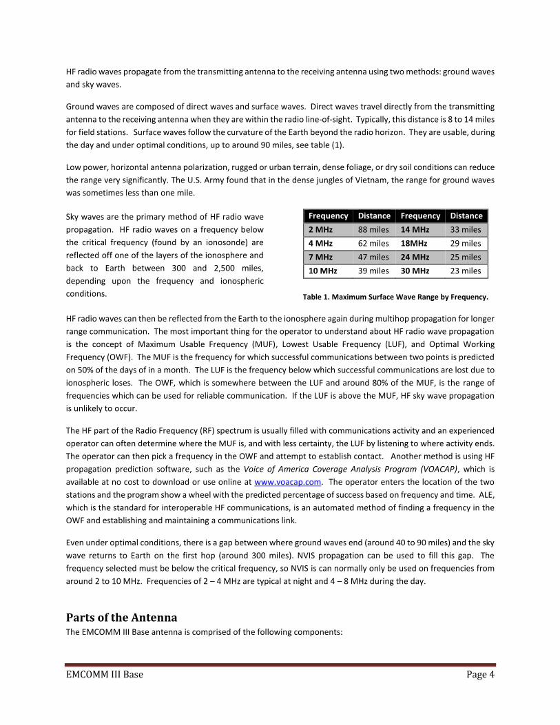
Sky waves are the primary method of HF radio wave
propagation. HF radio waves on a frequency below
the critical frequency (found by an ionosonde) are
reflected off one of the layers of the ionosphere and
back to Earth between 300 and 2,500 miles,
depending upon the frequency and ionospheric
conditions.
Frequency Distance Frequency Distance
2 MHz 88 miles 14 MHz 33 miles
4 MHz 62 miles 18MHz 29 miles
7 MHz 47 miles 24 MHz 25 miles
10 MHz 39 miles 30 MHz 23 miles
Table 1. Maximum Surface Wave Range by Frequency.
HF radio waves can then be reflected from the Earth to the ionosphere again during multihop propagation for longer
range communication. The most important thing for the operator to understand about HF radio wave propagation
is the concept of Maximum Usable Frequency (MUF), Lowest Usable Frequency (LUF), and Optimal Working
Frequency (OWF). The MUF is the frequency for which successful communications between two points is predicted
on 50% of the days of in a month. The LUF is the frequency below which successful communications are lost due to
ionospheric loses. The OWF, which is somewhere between the LUF and around 80% of the MUF, is the range of
frequencies which can be used for reliable communication. If the LUF is above the MUF, HF sky wave propagation
is unlikely to occur.
The HF part of the Radio Frequency (RF) spectrum is usually filled with communications activity and an experienced
operator can often determine where the MUF is, and with less certainty, the LUF by listening to where activity ends.
The operator can then pick a frequency in the OWF and attempt to establish contact. Another method is using HF
propagation prediction software, such as the Voice of America Coverage Analysis Program (VOACAP), which is
available at no cost to download or use online at www.voacap.com. The operator enters the location of the two
stations and the program show a wheel with the predicted percentage of success based on frequency and time. ALE,
which is the standard for interoperable HF communications, is an automated method of finding a frequency in the
OWF and establishing and maintaining a communications link.
Even under optimal conditions, there is a gap between where ground waves end (around 40 to 90 miles) and the sky
wave returns to Earth on the first hop (around 300 miles). NVIS propagation can be used to fill this gap. The
frequency selected must be below the critical frequency, so NVIS is can normally only be used on frequencies from
around 2 to 10 MHz. Frequencies of 2 – 4 MHz are typical at night and 4 – 8 MHz during the day.
Parts of the Antenna The EMCOMM III Base antenna is comprised of the following components:
EMCOMM III Base Page 5
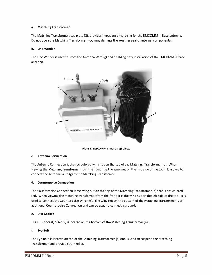
a. Matching Transformer
The Matching Transformer, see plate (2), provides impedance matching for the EMCOMM III Base antenna.
Do not open the Matching Transformer, you may damage the weather seal or internal components.
b. Line Winder
The Line Winder is used to store the Antenna Wire (g) and enabling easy installation of the EMCOMM III Base
antenna.
Plate 2. EMCOMM III Base Top View.
c. Antenna Connection
The Antenna Connection is the red colored wing nut on the top of the Matching Transformer (a). When
viewing the Matching Transformer from the front, it is the wing nut on the rind side of the top. It is used to
connect the Antenna Wire (g) to the Matching Transformer.
d. Counterpoise Connection
The Counterpoise Connection is the wing nut on the top of the Matching Transformer (a) that is not colored
red. When viewing the matching transformer from the front, it is the wing nut on the left side of the top. It is
used to connect the Counterpoise Wire (m). The wing nut on the bottom of the Matching Transformer is an
additional Counterpoise Connection and can be used to connect a ground.
e. UHF Socket
The UHF Socket, SO-239, is located on the bottom of the Matching Transformer (a).
f. Eye Bolt
The Eye Bold is located on top of the Matching Transformer (a) and is used to suspend the Matching
Transformer and provide strain relief.
EMCOMM III Base Page 6
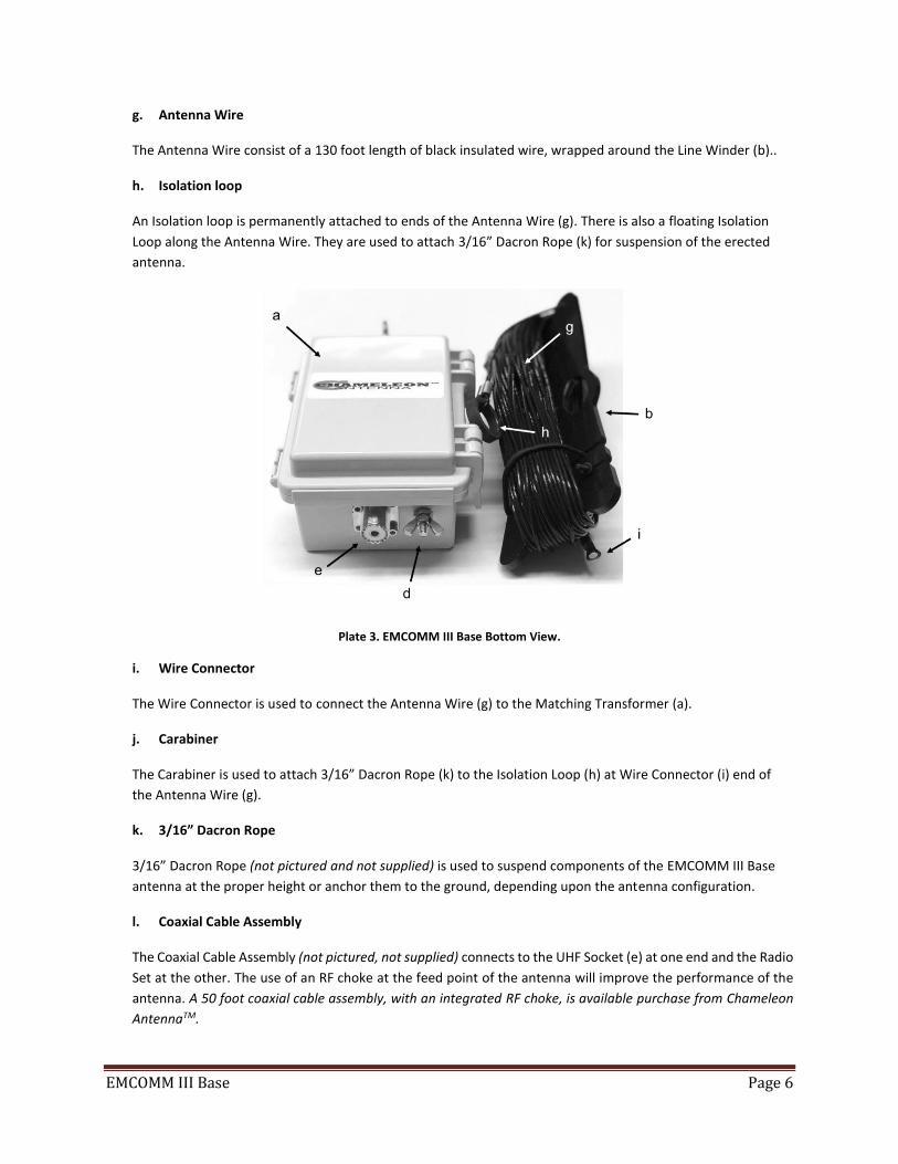
g. Antenna Wire
The Antenna Wire consist of a 130 foot length of black insulated wire, wrapped around the Line Winder (b)..
h. Isolation loop
An Isolation loop is permanently attached to ends of the Antenna Wire (g). There is also a floating Isolation
Loop along the Antenna Wire. They are used to attach 3/16” Dacron Rope (k) for suspension of the erected
antenna.
Plate 3. EMCOMM III Base Bottom View.
i. Wire Connector
The Wire Connector is used to connect the Antenna Wire (g) to the Matching Transformer (a).
j. Carabiner
The Carabiner is used to attach 3/16” Dacron Rope (k) to the Isolation Loop (h) at Wire Connector (i) end of
the Antenna Wire (g).
k. 3/16” Dacron Rope
3/16” Dacron Rope (not pictured and not supplied) is used to suspend components of the EMCOMM III Base
antenna at the proper height or anchor them to the ground, depending upon the antenna configuration.
l. Coaxial Cable Assembly
The Coaxial Cable Assembly (not pictured, not supplied) connects to the UHF Socket (e) at one end and the Radio
Set at the other. The use of an RF choke at the feed point of the antenna will improve the performance of the
antenna. A 50 foot coaxial cable assembly, with an integrated RF choke, is available purchase from Chameleon
AntennaTM.
EMCOMM III Base Page 7
m. Counterpoise Wire
The Counterpoise Wire (not pictured, not supplied) is highly recommend for use in most configurations of the
EMCOMM III Base antenna.
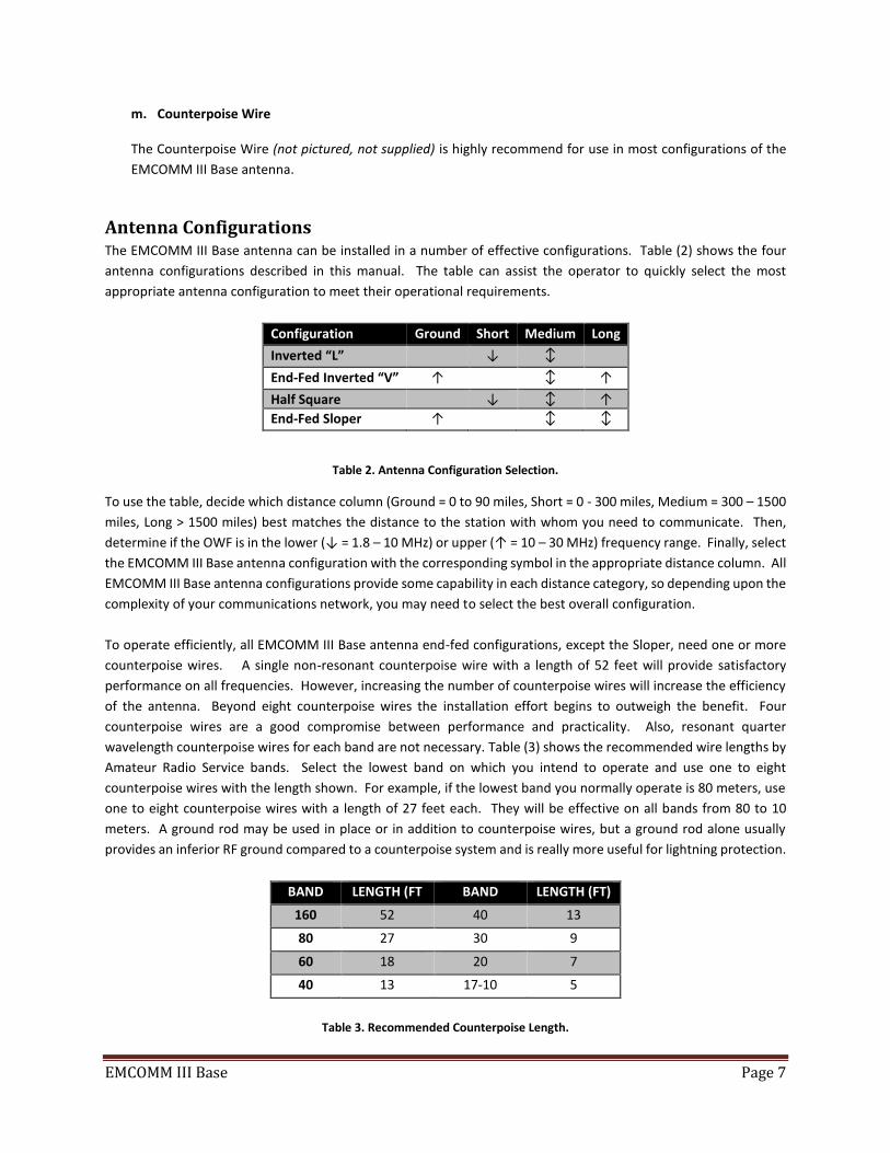
Antenna Configurations The EMCOMM III Base antenna can be installed in a number of effective configurations. Table (2) shows the four
antenna configurations described in this manual. The table can assist the operator to quickly select the most
appropriate antenna configuration to meet their operational requirements.
Configuration Ground Short Medium Long
Inverted “L” ↓ ↕
End-Fed Inverted “V” ↑ ↕ ↑
Half Square ↓ ↕ ↑
End-Fed Sloper ↑ ↕ ↕
Table 2. Antenna Configuration Selection.
To use the table, decide which distance column (Ground = 0 to 90 miles, Short = 0 - 300 miles, Medium = 300 – 1500
miles, Long > 1500 miles) best matches the distance to the station with whom you need to communicate. Then,
determine if the OWF is in the lower (↓ = 1.8 – 10 MHz) or upper (↑ = 10 – 30 MHz) frequency range. Finally, select
the EMCOMM III Base antenna configuration with the corresponding symbol in the appropriate distance column. All
EMCOMM III Base antenna configurations provide some capability in each distance category, so depending upon the
complexity of your communications network, you may need to select the best overall configuration.
To operate efficiently, all EMCOMM III Base antenna end-fed configurations, except the Sloper, need one or more
counterpoise wires. A single non-resonant counterpoise wire with a length of 52 feet will provide satisfactory
performance on all frequencies. However, increasing the number of counterpoise wires will increase the efficiency
of the antenna. Beyond eight counterpoise wires the installation effort begins to outweigh the benefit. Four
counterpoise wires are a good compromise between performance and practicality. Also, resonant quarter
wavelength counterpoise wires for each band are not necessary. Table (3) shows the recommended wire lengths by
Amateur Radio Service bands. Select the lowest band on which you intend to operate and use one to eight
counterpoise wires with the length shown. For example, if the lowest band you normally operate is 80 meters, use
one to eight counterpoise wires with a length of 27 feet each. They will be effective on all bands from 80 to 10
meters. A ground rod may be used in place or in addition to counterpoise wires, but a ground rod alone usually
provides an inferior RF ground compared to a counterpoise system and is really more useful for lightning protection.
BAND LENGTH (FT BAND LENGTH (FT)
160 52 40 13
80 27 30 9
60 18 20 7
40 13 17-10 5
Table 3. Recommended Counterpoise Length.

EMCOMM III Base Page 8
Inverted “L” Configuration
The EMCOMM III Base antenna, Inverted “L” configuration, see figure (1), is a multi-band short to medium range HF
antenna. It is a general-purpose antenna and when installed at a height of around 35 feet, will provide good sky
wave propagation (including NVIS). This configuration is predominately omnidirectional on lower frequencies,
slightly favoring the end of the antenna on upper frequencies. It is also very good for stealthy, small lot installation,
such in a suburban housing development. Try to install the antenna as high and straight as possible in an “L” shape,
but bending the antenna to use trees, a flag pole, the eaves of a house, or a non-conductive fence and supports will
still get you on-the-air and provide satisfactory results.
Figure 1. Inverted “L” Configuration.
End-Fed Inverted “V” Configuration
The EMCOMM III Base antenna, End-Fed Inverted “V” configuration, see figure (2), is a multi-band short to long
range HF antenna. It should provide medium range sky wave propagation on the lower frequencies and long range
(DX) sky wave propagation on the upper frequencies when the apex of the antenna is installed at a height of around
35 feet. This configuration is predominately omnidirectional on lower frequencies and predominantly bi-directional
broadside to the antenna on upper frequencies. This configuration is good when you have only one tall support.
The ends can be brought closer together to form a horizontal “V”, if needed, but the angle should be kept above 120
degrees for best results on the lower frequencies. The antenna will become somewhat directional toward the
opening of the “V” on the upper frequencies.

EMCOMM III Base Page 9
Figure 2. End-Fed Inverted “V” Configuration.
Half Square Configuration
The EMCOMM III Base antenna, Half Square configuration, see figure (3), is a multi-band short to long range HF
antenna. In this configuration, performance is enhanced from 7 to 20 MHz (40 to 17 meters) while somewhat
reduced above and below those frequencies. It should provide acceptable medium range sky wave propagation
(including NVIS) on frequencies below 7 MHz, long range (DX) sky wave propagation from 7 to 20 MHz, and medium
range sky wave propagation from 20 to 30 MHz. It is omni-directional below 7 MHz, bi-directional broadside to the
antenna from around 7 MHz (40 meters) and favoring the ends above 7 MHz. The dimensions of this configuration
are more critical to the performance of the antenna then in the other configurations.
Figure 3. Half Square Configuration.

EMCOMM III Base Page 10
End-Fed Sloper
The EMCOMM III Base antenna End-Fed Sloper configuration, see figure (4), is a medium to long range multi-band
HF antenna. The End-Fed Sloper is a good choice if you already have a metal antenna tower or mast. The tower or
mast is used as the ground counterpoise in this configuration. It is omni-directional on lower frequencies and
unidirectional in the direction of the sloped wire on the higher frequencies.
Figure 4. End-Fed Sloper Configuration.
Installation Site Selection and Preparation.
1. Select a site to deploy the EMCOMM III Base
antenna. The best site should have sufficient
supports for the configuration selected. The
EMCOMM III Base antenna is very good for
stealthy, small lot installation, such in a suburban
housing development. Try to install the antenna
as high and straight as possible in the shape of
the configuration selected, but bending the
antenna to use trees, a flag pole, the eaves of a
house, or a non-conductive fence will still get you
on-the-air and provide satisfactory results.
2. Unwind the Antenna Wire (g) from the Line
Winder (b).
3. Tie a Bowline or similar knot that forms a loop
from a 3/16” Dacron Rope (k) to the Eye Bolt (f).
This will be used for strain relief and to suspend
or anchor the Matching Transformer (a),
depending upon the configuration.
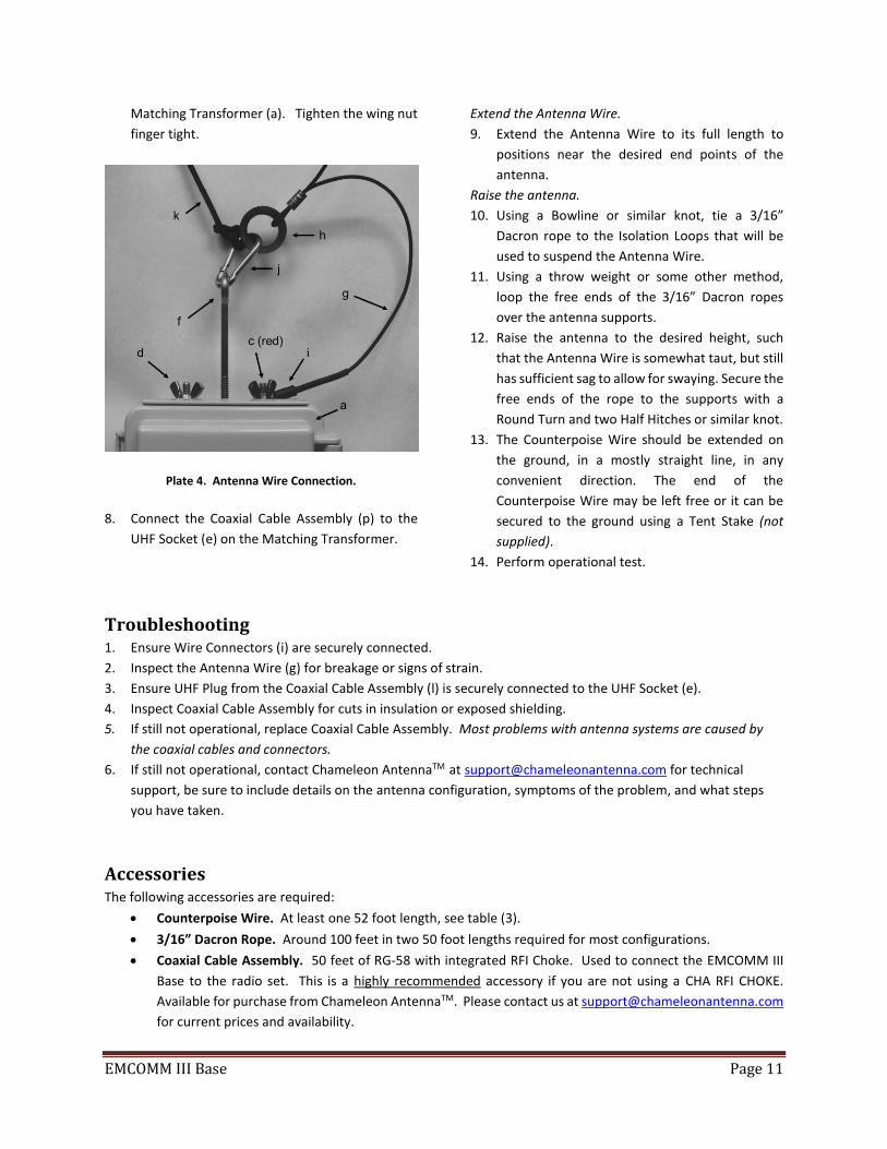
Connect the Matching Transformer. Refer to plates
(2) through (4) for following steps.
4. Attach a Carabiner to the Isolation Loop (h) on
the Wire Connector (i) end of the Antenna Wire
(g).
5. Connect the Wire Connector from the Antenna
Wire to the Antenna Connection (c). Tighten the
wing nut finger tight.
6. Hook the Carabiner to the 3/16” Dacron Rope
loop from step (3). This provides strain relief.
7. Connect the Counterpoise Wire (not supplied) to
the Counterpoise Connection (d) on the
EMCOMM III Base Page 11
Matching Transformer (a). Tighten the wing nut
finger tight.
Plate 4. Antenna Wire Connection.
8. Connect the Coaxial Cable Assembly (p) to the
UHF Socket (e) on the Matching Transformer.
Extend the Antenna Wire.
9. Extend the Antenna Wire to its full length to
positions near the desired end points of the
antenna.
Raise the antenna.
10. Using a Bowline or similar knot, tie a 3/16”
Dacron rope to the Isolation Loops that will be
used to suspend the Antenna Wire.
11. Using a throw weight or some other method,
loop the free ends of the 3/16” Dacron ropes
over the antenna supports.
12. Raise the antenna to the desired height, such
that the Antenna Wire is somewhat taut, but still
has sufficient sag to allow for swaying. Secure the
free ends of the rope to the supports with a
Round Turn and two Half Hitches or similar knot.
13. The Counterpoise Wire should be extended on
the ground, in a mostly straight line, in any
convenient direction. The end of the
Counterpoise Wire may be left free or it can be
secured to the ground using a Tent Stake (not
supplied).
14. Perform operational test.
Troubleshooting 1. Ensure Wire Connectors (i) are securely connected.
2. Inspect the Antenna Wire (g) for breakage or signs of strain.
3. Ensure UHF Plug from the Coaxial Cable Assembly (l) is securely connected to the UHF Socket (e).
4. Inspect Coaxial Cable Assembly for cuts in insulation or exposed shielding.
5. If still not operational, replace Coaxial Cable Assembly. Most problems with antenna systems are caused by
the coaxial cables and connectors.
6. If still not operational, contact Chameleon AntennaTM at [email protected] for technical
support, be sure to include details on the antenna configuration, symptoms of the problem, and what steps
you have taken.
Accessories The following accessories are required:
• Counterpoise Wire. At least one 52 foot length, see table (3).
• 3/16” Dacron Rope. Around 100 feet in two 50 foot lengths required for most configurations.
• Coaxial Cable Assembly. 50 feet of RG-58 with integrated RFI Choke. Used to connect the EMCOMM III
Base to the radio set. This is a highly recommended accessory if you are not using a CHA RFI CHOKE.
Available for purchase from Chameleon AntennaTM. Please contact us at [email protected]
for current prices and availability.
EMCOMM III Base Page 12
Specifications • Frequency: 3.5 MHz through 30.0 MHz continuous (including all Amateur Radio Service bands 80m to
10m). Can be used from 1.8 to 3.5 MHz (160m Amateur Radio Service band) with a wide-range antenna
tuner or coupler.
• Power: 250 W continuous duty cycle (CW, AM, FM, RTTY), 500 W intermittent duty cycle (SSB and SSB-
based digital modes)
• RF Connection: UHF Plug (PL-259)
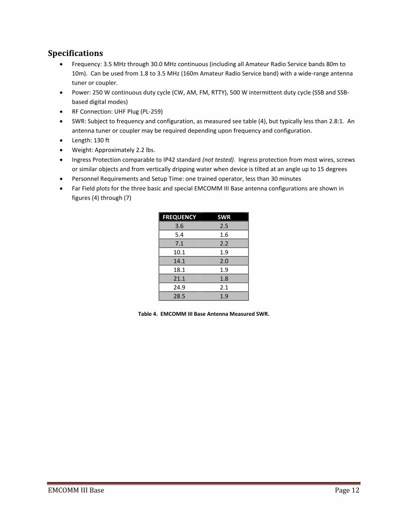
• SWR: Subject to frequency and configuration, as measured see table (4), but typically less than 2.8:1. An
antenna tuner or coupler may be required depending upon frequency and configuration.
• Length: 130 ft
• Weight: Approximately 2.2 lbs.
• Ingress Protection comparable to IP42 standard (not tested). Ingress protection from most wires, screws
or similar objects and from vertically dripping water when device is tilted at an angle up to 15 degrees
• Personnel Requirements and Setup Time: one trained operator, less than 30 minutes
• Far Field plots for the three basic and special EMCOMM III Base antenna configurations are shown in
figures (4) through (7)
FREQUENCY SWR
3.6 2.5
5.4 1.6
7.1 2.2
10.1 1.9
14.1 2.0
18.1 1.9
21.1 1.8
24.9 2.1
28.5 1.9
Table 4. EMCOMM III Base Antenna Measured SWR.
EMCOMM III Base Page 13
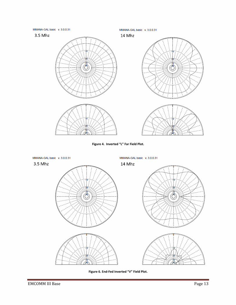
Figure 4. Inverted “L” Far Field Plot.
Figure 6. End-Fed Inverted “V” Field Plot.

EMCOMM III Base Page 14
Figure 6. Half Square Far Field Plot.
Figure 7. End-Fed Sloper Far Field Plot.

EMCOMM III Base Page 15
Chameleon AntennaTM Products The following products are available for purchase at Chameleon AntennaTM.
Go to http://chameleonantenna.com for ordering and more information.
CHA P-LOOP 2.0 - The CHA P-LOOP 2.0 was designed
with portability, ease of use simplicity, ruggedness
and high performance in mind. Unlike any other
similar antennas on the market, the CHA P-LOOP 2.0
is made with premium materials that are precisely
manufactured and assembled in the USA! This is an
exciting new product from Chameleon Antenna.
Easily deployable HF magnetic loop antennas, also
called small transmitting loops, have been routinely
used for many years in military, diplomatic, and
shipboard HF communication links, where robust and
reliable general coverage radio communication is a
necessity. Covers 7.0-29.7 MHz.
CHA F-LOOP 2.0 – The CHA F-LOOP 2.0 was designed
with portability, ease of use simplicity, ruggedness
and high performance in mind. Unlike any other
similar antennas on the market, the CHA F-LOOP 2.0
is made with premium materials that are precisely
manufactured and assembled in the USA! Easily
deployable HF magnetic loop antennas, also called
small transmitting loops, have been routinely used for
many years in military, diplomatic, and shipboard HF
communication links, where robust and reliable
general coverage radio communication is a necessity.
Covers 3.5-29.7 MHz.
CHA WINDOM 40 – The CHA WINDOM 40 Antenna is
designed for 40, 20, and 10 meters. Amateur Bands
from 60 through 10 meters can be operated using an
antenna tuner. Built with the portable operator in
mind, it is very light weight, easy to set up, and comes
with a military-style pouch.
CHA SKYLOOP - The CHA SKYLOOP is a 250' full wave
loop antenna cut for 80M. With the help of an
antenna tuner, the CHA SKYLOOP will cover all the
bands between 80M and 6M.
CHA Hybrid Mini – Portable HF Antenna Base - The
CHA HYBRID-MINI Base is the portable version of the
regular HYBRID. The unit can be differentiated by the
color of the lid and the base connector, which is black
instead of gray. The HYBRID-MINI is also smaller and
about 50% lighter than the regular HYBRID. An
external antenna tuner is required to provide a low
VSWR. The connector provided with the antenna is a
SO-239 sealed. The entire unit is also waterproof. The
HYBRID-MINI will serve as impedance transformer
matching network and will greatly reduce the VSWR
at the load for the following antennas: V1, V1L, V2L
and MIL.
CHA V2L Mobile Antenna - The CHA V2L is a rugged
multiband HF antenna designed for smaller vehicles.
CHA VHF/UHF Magnetic Mount Mobile Antenna -
The CHA VHF/UHF is a simple but great dual band
antenna for 2M and 70CM.
CHA MIL Whip - The CHA MIL whip is a broadband (28
to 54 MHz) monopole antenna designed for portable
or man-pack radios requiring compact but rugged
antenna systems. Its design has been borrowed from
similar antennas utilized by many armies all over the
world. The CHA MIL is very hardy, sturdy and portable
(being collapsible). Un-mounted the entire antenna
length is less than 29”. The 5 aluminum sections are
hold together by a piece of 1/8th inch US GI MIL SPEC
shock cord. The CHA MIL Whip and a CHA HYBRID-
MINI Base perfectly complements the capability of
the CHA HYBRID - MINI / MICRO.
CHA MIL EXT Whip Extension - The CHA MIL EXT whip
has been designed to offer maximum portability and
performance for those already using the portable
CHA MIL whip for man-pack antenna system. This
collapsible antenna extension needs to be used with
the CHA MIL to create a 17’4” long portable antenna.
When combined with any HYBRID series antenna
bases the CHA MIL EXT will operate at all frequencies
in the 1.8-54 MHz band without any adjustment with
most modern external antenna tuners.
EMCOMM III Base Page 16
CHA TD Terminated Dipole 2.0 - The CHA TD 2.0 is a
HF broadband antenna specially designed for
portable HF communication where rapid deployment
and simplicity of operation is essential but
compactness is a primary consideration. The antenna
will operate at all frequencies in the 1.8-54 MHz band
without any adjustment with most modern internal
antenna tuners. No masts or guying are required.
CHA TD Tactical Dipole - The CHA TD (Tactical Dipole)
Antenna is a HF broadband antenna specially
designed for portable HF communication where rapid
deployment and simplicity of operation is essential.
The antenna will operate at all frequencies in the 1.8-
30 MHz band without any adjustment with most
modern internal antenna tuners. It is ideal for use in
conjunction with modern, digitally configured, HF
communication transceivers where features such as
ALE and frequency hopping require true broadband
capability. The antenna will work successfully
supported by trees, masts, the tops of vehicles or any
convenient object or structure. The CHA TD can also
be used without antenna tuner, as the SWR will stay
under 2.5:1 between 10M and 80M and under 2.75:1
on 160M.
CHA FT-817 BRACKETS 2.0 – CHA FT-817 Brackets are
built exclusively by the skilled machinists of
Chameleon AntennaTM. It is a military-style pair of
precision fabricated brackets and high quality
carrying strap for the popular Yaesu FT-817 series
portable QRP transceiver. The CHA FT-817 Brackets
will ruggedize and help protect your FT-817 from the
many hazards of field operations.
References 1. Silver, H. Ward (editor), 2013, 2014 ARRL Handbook for Radio Communications, 91st Edition, American Radio
Relay League, Newington, CT.
2. 1987, Tactical Single-Channel Radio Communications Techniques (FM 24-18), Department of the Army,
Washington, DC.
3. Turkes, Gurkan, 1990, Tactical HF Field Expedient Antenna Performance Volume I Thesis, U.S. Naval Post
Graduate School, Monterey, CA.


![Design of a Blade Antenna Embedded in Low Cost Dielectric ...€¦ · One of the most installed antenna on aircraft is the monopole [1]. Although cylindrical monopoles are easy to](https://static.fdocuments.us/doc/165x107/5f28979f5e797573e95977b1/design-of-a-blade-antenna-embedded-in-low-cost-dielectric-one-of-the-most-installed.jpg)