EMC® VMAX® Best Practices Guide for AC Power Connections For ...
28
EMC ® VMAX ® Best Practices Guide for AC Power Connections For: VMAX3 ™ Family: VMAX 100K, 200K, 400K VMAX All Flash: 450F, 450FX, 850F, 850FX REVISION 03
Transcript of EMC® VMAX® Best Practices Guide for AC Power Connections For ...

EMC® VMAX®
Best Practices Guidefor AC Power Connections
For:VMAX3™ Family: VMAX 100K, 200K, 400KVMAX All Flash: 450F, 450FX, 850F, 850FXREVISION 03

Copyright © 2014-2016 EMC Corporation. All rights reserved. Published in the USA.
Published February, 2016
EMC believes the information in this publication is accurate as of its publication date. The information is subject to changewithout notice.
The information in this publication is provided as is. EMC Corporation makes no representations or warranties of any kind withrespect to the information in this publication, and specifically disclaims implied warranties of merchantability or fitness for aparticular purpose. Use, copying, and distribution of any EMC software described in this publication requires an applicablesoftware license.
EMC², EMC, and the EMC logo are registered trademarks or trademarks of EMC Corporation in the United States and othercountries. All other trademarks used herein are the property of their respective owners.
For the most up-to-date regulatory document for your product line, go to EMC Online Support (https://support.emc.com).
EMC CorporationHopkinton, Massachusetts 01748-91031-508-435-1000 In North America 1-866-464-7381www.EMC.com
2 Best Practices Guide for AC Power Connections For: VMAX3 Family: VMAX 100K, 200K, 400KVMAX All Flash: 450F, 450FX, 850F, 850FX

5
7
Preface 9
Revision history.............................................................................................13
Best Practices Guide for AC Power Connections 15
Best practices overview for AC power connections.........................................16Selecting the proper AC power connection procedure....................................17Procedure A: Working with customer's electrician onsite............................... 18
Procedure A-1: Customer's electrician.............................................. 19Procedure A-2: EMC Customer Engineer............................................20Procedure A-3: Customer's electrician.............................................. 23
Procedure B: Verify and connect....................................................................24Procedure C: Obtain customer verification.....................................................25Labeling the PDUs......................................................................................... 26AC power specifications................................................................................ 28
Figures
Tables
Chapter 1
CONTENTS
Best Practices Guide for AC Power Connections For: VMAX3 Family: VMAX 100K, 200K, 400KVMAX All Flash: 450F, 450FX, 850F, 850FX
3

CONTENTS
4 Best Practices Guide for AC Power Connections For: VMAX3 Family: VMAX 100K, 200K, 400KVMAX All Flash: 450F, 450FX, 850F, 850FX
Two independent customer-supplied PDUs....................................................................16Circuit breakers ON — AC power within specification..................................................... 19Circuit breakers OFF — No AC power...............................................................................19Connecting AC power, single-phase............................................................................... 20Connecting AC power, three-phase................................................................................ 21Power zone connections................................................................................................ 22PDU label , single-phase and three-phase......................................................................26Label placement— Customer PDU Information............................................................... 27
12345678
FIGURES
Best Practices Guide for AC Power Connections For: VMAX3 Family: VMAX 100K, 200K, 400KVMAX All Flash: 450F, 450FX, 850F, 850FX
5

FIGURES
6 Best Practices Guide for AC Power Connections For: VMAX3 Family: VMAX 100K, 200K, 400KVMAX All Flash: 450F, 450FX, 850F, 850FX

Typographical conventions used in this content.............................................................10Procedure options for AC power connection .................................................................. 17Label part numbers and location ...................................................................................26Input power requirements - single-phase, North American, International, Australian ..... 28Input power requirements - three-phase, North American, International, Australian ...... 28
12345
TABLES
Best Practices Guide for AC Power Connections For: VMAX3 Family: VMAX 100K, 200K, 400KVMAX All Flash: 450F, 450FX, 850F, 850FX
7

TABLES
8 Best Practices Guide for AC Power Connections For: VMAX3 Family: VMAX 100K, 200K, 400KVMAX All Flash: 450F, 450FX, 850F, 850FX

Preface
Contact your EMC technical support professional if a product does not function properlyor does not function as described in this document.
Note
This document was accurate at publication time. Go to EMC Online Support (https://support.emc.com) to ensure that you are using the latest version of this document.
PurposeThis document describes best practices for connecting AC power to the following VMAXarrays:l VMAX3 Family: VMAX 100K, VMAX 200K, VMAX 400Kl VMAX All Flash: VMAX 450F, VMAX 450FX, VMAX 850F, VMAX 850FX
AudienceThis document is intended for customers who are installing a VMAX3 Family orVMAX All Flash array and must assure that fault tolerant AC power is supplied to thearrays from independent, customer-supplied, power distribution units (PDUs).
Related documentationThe following EMC publications provide additional information:
EMC VMAX3 Family Product Guide for VMAX 100K, VMAX 200K, VMAX 400K with HYPERMAXOS
Provides product information regarding the purchase of a VMAX3 Family 100K, 200K,400K.
EMC VMAX All Flash Product Guide for VMAX 450F, 450FX , 850F, 850FX with HYPERMAX OS
Provides product information regarding the purchase of a VMAX 450F, 450FX , 850F,850FX with HYPERMAX OS.
EMC VMAX3 Family Site Planning Guide for VMAX 100K, VMAX 200K, VMAX 400K
Provides planning information regarding the purchase and installation of a VMAX3Family 100K, 200K, 400K.
EMC VMAX All Flash Site Planning Guide for VMAX 450F, 450FX , 850F, 850FX withHYPERMAX OS
Provides planning information regarding the purchase and installation of a VMAX450F, 450FX , 850F, 850FX with HYPERMAX OS.
EMC VMAX Securing Kit Installation Guide
Describes how to install the securing kit on a VMAX3 Family array or VMAX All Flasharray.
EMC VMAX Power-down/Power-up Procedure
Describes how to power-down and power-up a VMAX3 Family array or VMAX All Flasharray.
SolVe Desktop
Provides links to documentation, procedures for common tasks, and connectivityinformation for 2-site and 3-site SRDF configurations. To download the SolVeDesktop tool, go to EMC Online Support at https://support.EMC.com and search for
Preface 9

SolVe Desktop. Download the SolVe Desktop and load the VMAX Family and DMXprocedure generator.
Note
You need to authenticate (authorize) your SolVe Desktop. After it is installed,familiarize yourself with the information under Help tab.
Special notice conventions used in this documentEMC uses the following conventions for special notices:
DANGER
Indicates a hazardous situation which, if not avoided, will result in death or seriousinjury.
WARNING
Indicates a hazardous situation which, if not avoided, could result in death or seriousinjury.
CAUTION
Indicates a hazardous situation which, if not avoided, could result in minor or moderateinjury.
NOTICE
Addresses practices not related to personal injury.
Note
Presents information that is important, but not hazard-related.
Typographical conventionsEMC uses the following type style conventions in this document:
Table 1 Typographical conventions used in this content
Bold Used for names of interface elements, such as names of windows,dialog boxes, buttons, fields, tab names, key names, and menu paths(what the user specifically selects or clicks)
Italic Used for full titles of publications referenced in text
Monospace Used for:
l System code
l System output, such as an error message or script
l Pathnames, filenames, prompts, and syntax
l Commands and options
Monospace italic Used for variables
Monospace bold Used for user input
[ ] Square brackets enclose optional values
Preface
10 Best Practices Guide for AC Power Connections For: VMAX3 Family: VMAX 100K, 200K, 400KVMAX All Flash: 450F, 450FX, 850F, 850FX

Table 1 Typographical conventions used in this content (continued)
| Vertical bar indicates alternate selections - the bar means “or”
{ } Braces enclose content that the user must specify, such as x or y or z
... Ellipses indicate nonessential information omitted from the example
Where to get helpEMC support, product, and licensing information can be obtained as follows:
Product information
EMC technical support, documentation, release notes, software updates, orinformation about EMC products can be obtained on the https://support.emc.comsite (registration required).
Technical support
To open a service request through the https://support.emc.com site, you must havea valid support agreement. Contact your EMC sales representative for details aboutobtaining a valid support agreement or to answer any questions about your account.
eLicensing support
To activate your entitlements and obtain your VMAX license files, visit the ServiceCenter on https://support.EMC.com, as directed on your License Authorization Code(LAC) letter emailed to you.
l For help with missing or incorrect entitlements after activation (that is, expectedfunctionality remains unavailable because it is not licensed), contact your EMCAccount Representative or Authorized Reseller.
l For help with any errors applying license files through Solutions Enabler, contactthe EMC Customer Support Center.
l If you are missing a LAC letter, or require further instructions on activating yourlicenses through the Online Support site, contact EMC's worldwide Licensingteam at [email protected] or call:
n North America, Latin America, APJK, Australia, New Zealand: SVC4EMC(800-782-4362) and follow the voice prompts.
n EMEA: +353 (0) 21 4879862 and follow the voice prompts.
EMC SolVe Desktop
EMC SolVe Desktop— Provides links to documentation, procedures for commontasks, and connectivity information for 2-site and 3-site SRDF configurations. SolVeautomatically provides relevant alerts from the EMC knowledgebase and FCOs. Todownload the SolVe Desktop tool, go to EMC Online Support at https://support.emc.com and search for SolVe Desktop. In the search results, click theSolVe Desktop to download and install. Within the SolVe Deskop, select anddownload the VMAX Family and DMX procedure generator.
Note
l You need to authenticate (authorize) your SolVe Desktop. Once it is installed,please familiarize yourself with the information under Help tab.
l The executable date does not reflect the version of the generators.
Preface
11

Your commentsYour suggestions help us improve the accuracy, organization, and overall quality of thedocumentation. Send your comments and feedback to: [email protected]
Preface
12 Best Practices Guide for AC Power Connections For: VMAX3 Family: VMAX 100K, 200K, 400KVMAX All Flash: 450F, 450FX, 850F, 850FX
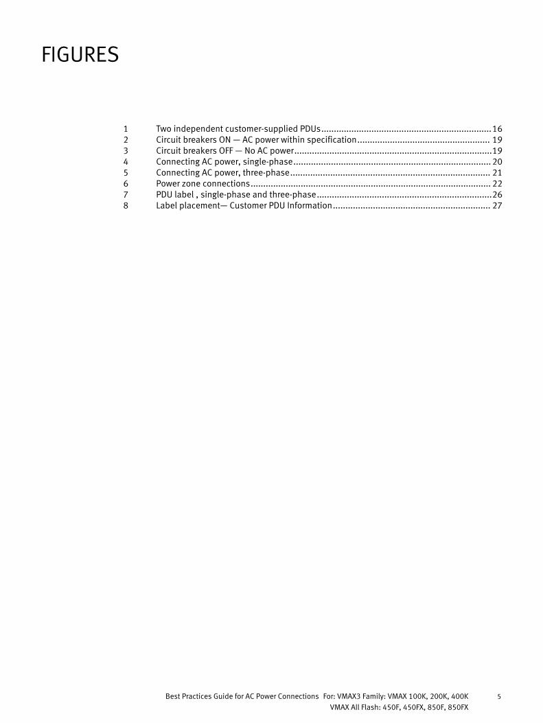
Revision historyThe following table presents the revision history of this document:
Revision Description and/orChange
Date
01 Initial release September, 2014
02 Format change. No changein content.
August, 2015
03 Updated name and docreferences. Minor edits forreadability. Modifiedfrontmatter.
February, 2016
Preface
Revision history 13

Preface
14 Best Practices Guide for AC Power Connections For: VMAX3 Family: VMAX 100K, 200K, 400KVMAX All Flash: 450F, 450FX, 850F, 850FX

CHAPTER 1
Best Practices Guide for AC Power Connections
l Best practices overview for AC power connections.................................................16l Selecting the proper AC power connection procedure............................................ 17l Procedure A: Working with customer's electrician onsite....................................... 18l Procedure B: Verify and connect............................................................................24l Procedure C: Obtain customer verification.............................................................25l Labeling the PDUs................................................................................................. 26l AC power specifications........................................................................................ 28
Best Practices Guide for AC Power Connections 15

Best practices overview for AC power connectionsTo assure fault tolerant power, external AC power must be supplied from independent,customer-supplied, power distribution units (PDUs) as shown in Figure 1 on page 16.
NOTICE
For systems operating from three phase AC power, two independent and isolated ACpower sources are recommended for the two individual power zones in each rack of thesystem. This provides for the highest level of redundancy and system availability. Ifindependent AC power is not available, there is a higher risk of data unavailability shoulda power failure occur, including individual phase loss occurring in both power zones.
NOTICE
Before connecting external AC power to EMC bays, verify that the bays have been placedin their final position as explained in the installation guide.
Figure 1 Two independent customer-supplied PDUs
Customer’sPDU 1
Customer’sPDU 2
Circuit breakerson (|)
Circuit breakerson (|)
Circuit breakers - Numbers
27
28
29
30
Circuit breakers - Numbers
...
8
9
10
11
...
Power feed 1 Power feed 2
Best Practices Guide for AC Power Connections
16 Best Practices Guide for AC Power Connections For: VMAX3 Family: VMAX 100K, 200K, 400KVMAX All Flash: 450F, 450FX, 850F, 850FX

Selecting the proper AC power connection procedureEMC Customer Engineer must select the proper AC power connection procedureTable 2 on page 17 summarizes possible scenarios at the installation site when you areabout to connect external AC power to the EMC array. Select the procedure that applies toyour situation.
Table 2 Procedure options for AC power connection
If the scenario is... then use this procedure:
The customer’s electrician is available at the installation site. Aa, See: Procedure A: Working withcustomer's electrician onsite on page 18
Access to customer-supplied, labeled, power cables (beneath raised floor oroverhead).
(And the customer’s electrician is NOT available at the installation site.)
B, See: Procedure B: Verify and connect onpage 24
Customer-supplied PDU source cables are already plugged into the EMC PDU andyou have no access to the customer-supplied, labeled, power cables (beneathraised floor or overhead).(And the customer’s electrician is NOT available at the installation site.)
C, See: Procedure C: Obtain customerverification on page 25
a. Procedure A assures fault tolerant power in the EMC array.
Best Practices Guide for AC Power Connections
Selecting the proper AC power connection procedure 17

Procedure A: Working with customer's electrician onsiteUse this procedure if the customer’s electrician is available at the installation site.
This procedure requires three basic tasks that alternate between the customer'selectrician, the EMC CE and back to the customer's electrician.
l Procedure A-1: Customer's electrician on page 19
l Procedure A-2: EMC Customer Engineer on page 20
l Procedure A-3: Customer's electrician on page 23
Best Practices Guide for AC Power Connections
18 Best Practices Guide for AC Power Connections For: VMAX3 Family: VMAX 100K, 200K, 400KVMAX All Flash: 450F, 450FX, 850F, 850FX

Procedure A-1: Customer's electrician
NOTICE
This task is performed by the customer's electrician.
Procedure
1. Verify that the customer-supplied AC source voltage output on each PDU is within theAC power specification shown in AC power specifications on page 28. Measure thevoltage output of each power cable as shown in Figure 2 on page 19.
2. Turn OFF all the relevant circuit breakers in customer-supplied PDU 1 and customer-supplied PDU 2.
3. Verify that the customer-supplied power cables connected to PDU 1 and PDU 2 haveno power as shown in Figure 3 on page 19.
Figure 2 Circuit breakers ON — AC power within specification
Customer’sPDU 1
Customer’sPDU 2
Circuit breakerson (|)
Circuit breakerson (|)
Circuit breakers - Numbers
27
28
29
30
Circuit breakers - Numbers
...
8
9
10
11
...
Labels on customer power lines
Power feed 1 Power feed 2
PDU 1CB 28
PDU 2
CB 9
Voltmeter
TYPE PM89 CLASS 25 01
0
100 240300V
Voltmeter
TYPE PM89 CLASS 25 01
0
100 240300V
Figure 3 Circuit breakers OFF — No AC power
Customer’sPDU 1
Customer’sPDU 2
Circuit breakeroff (0)
Circuit breakeroff (0)Circuit breakers - Numbers
27
28
29
30
Circuit breakers - Numbers
...
8
9
10
11
...
PDU 2
CB 9
PDU 1CB 28
Labels on customer power lines
Voltmeter
TYPE PM89 CLASS 25 01
0
100 240300V
Voltmeter
TYPE PM89 CLASS 25 01
0
100 240300V
Best Practices Guide for AC Power Connections
Procedure A-1: Customer's electrician 19

Procedure A-2: EMC Customer Engineer
NOTICE
This task is performed by the EMC Customer Engineer.
Procedure
1. Confirm that the customer-supplied power cables are labeled and that each labelcontains the relevant customer-supplied PDU and circuit breaker numbers. If powercables are not equipped with labels, alert the customer.
2. Compare the numbers on the customer-supplied power cables for each EMC bay toverify that power zone A and power zone B are powered by a different customer-supplied PDU.
3. If power extension cables are required, connect them to power zone A and power zoneB in each bay.
For single-phase, connect customer-supplied PDU power cables to the EMC bay byconnecting to the bay's AC input cables for power zone A and power zone B as shownin Figure 4 on page 20.
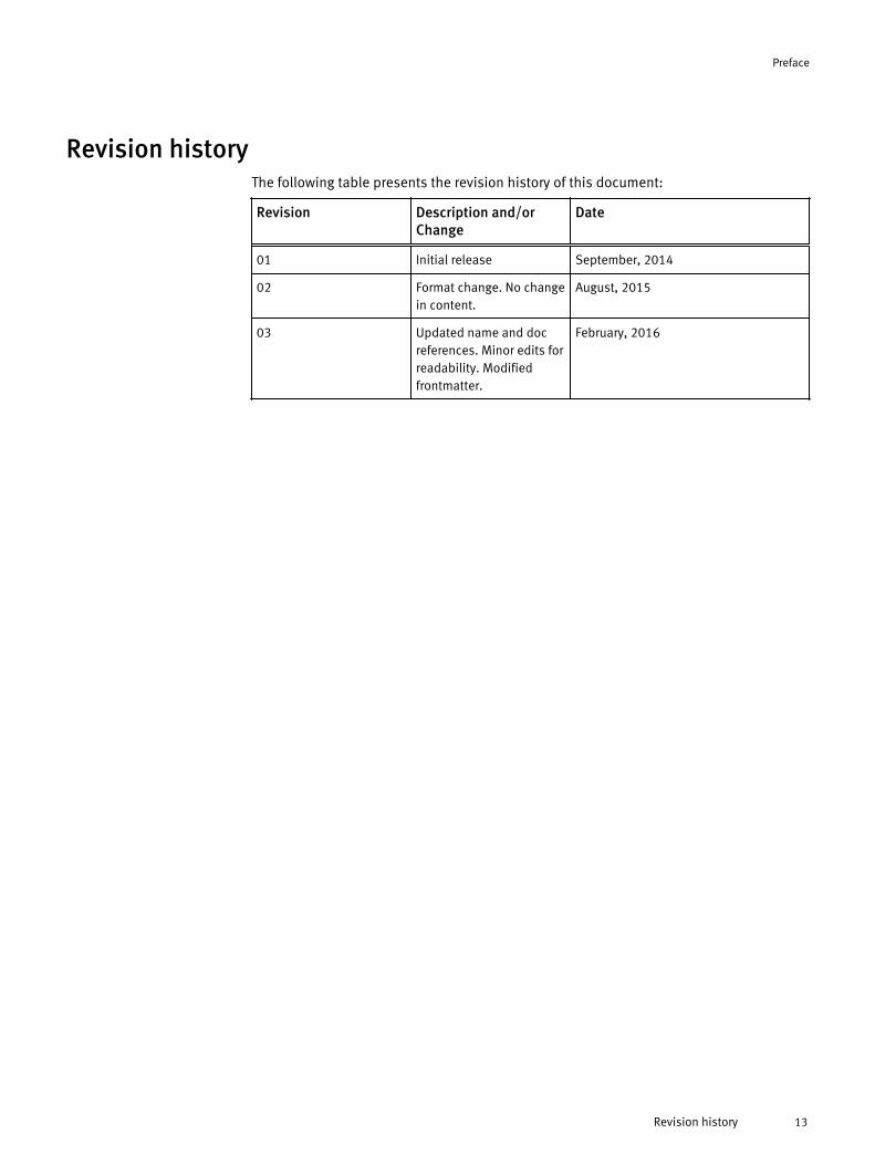
For three-phase, connect customer-supplied PDU power cables to the EMC bay byconnecting to the bay's AC input cables for power zone A and power zone B as shownin Figure 5 on page 21.
Figure 4 Connecting AC power, single-phase
Customer’s PDU 1
Zone B
AC input
cable B
15 ft. extension
cord options
Mating connector or
customer-supplied cable
Customer’s PDU 2
Zone A
AC input
cable A
15 ft. extension
cord options
Mating connector or
customer-supplied cable
EMC-supplied power cable
and connector from the PDUCable connectors are shown
as they exit the bottom rear
of the bay.
Rear view
System bay
Zone B PDU
(Left)
Zone A PDU
(Right)
EMC-supplied power cable
and connector from the PDU
P1 P2 P3 P1 P2 P3P2 and P3 used
depending on
configuration
Best Practices Guide for AC Power Connections
20 Best Practices Guide for AC Power Connections For: VMAX3 Family: VMAX 100K, 200K, 400KVMAX All Flash: 450F, 450FX, 850F, 850FX
Figure 5 Connecting AC power, three-phase
Customer’s PDU 1
Zone B
AC input
cable B
15 ft. extension
cord options
Mating connector or
customer-supplied cable
Customer’s PDU 2
Zone A
AC input
cable A
15 ft. extension
cord options
Mating connector or
customer-supplied cable
EMC-supplied power cable
and connector from the PDU
Rear view
System bay
Zone B PDU
(Left)
Zone A PDU
(Right)
EMC-supplied power cable
and connector from the PDU
Zone B PDU
(Left)
Zone A PDU
(Right)
Cable connectors are shown
as they exit the bottom rear
of the bay.
Best Practices Guide for AC Power Connections
Procedure A-2: EMC Customer Engineer 21

NOTICE
Do not connect EMC bay power zone A and power zone B to the same customer-supplied PDU. The customer will lose power redundancy and risk Data Unavailability(DU) if the PDU fails or is turned off during a maintenance procedure.
Figure 6 Power zone connections
:tnatropmIlaunam noitcurtsni ot refeR
Zone B Zone A
(Rear View)SYSTEM
Customer’s Power
Source 1
Circuit
Breakers
(CBs)
Zone B Zone A
(Rear View)SYSTEM
Customer’s Power
Source 1
Circuit
Breakers
(CBs)
Customer’s Power
Source 2
Circuit
Breakers
(CBs)
:tnatropmIlaunam noitcurtsni ot refeR
Zone B Zone A
(Rear View)SYSTEM
Customer’s Power
Source 1
Circuit
Breakers
(CBs)
Zone B Zone A
(Rear View)SYSTEM
Customer’s Power
Source 1
Circuit
Breakers
(CBs)
Customer’s Power
Source 2
Circuit
Breakers
(CBs)
046-001-749_01
Best Practices Guide for AC Power Connections
22 Best Practices Guide for AC Power Connections For: VMAX3 Family: VMAX 100K, 200K, 400KVMAX All Flash: 450F, 450FX, 850F, 850FX

Procedure A-3: Customer's electrician
NOTICE
This task is performed by the customer's electrician.
Procedure
1. Working with the EMC Customer Engineer, turn ON all the relevant circuit breakers incustomer-supplied PDU 2.
Verify that only power supply and/or SPS LEDs in power zone A are ON or flashinggreen in every bay in the array.
Note
If all power supply and/or SPS LEDs in a bay are ON or flashing green, the bay isincorrectly wired because the AC power to both EMC power zones is supplied by asingle PDU, that is, customer-supplied PDU 2. Wiring must be corrected before movingon to the next step.
2. Turn OFF the relevant circuit breakers in customer-supplied PDU 2.
Verify that the power supply and/or SPS LEDs that turned green in the previous stepchanged from green to OFF and/or flashing yellow. The yellow SPS lights flash for amaximum of 5 minutes.
Note
Note that power supplies connected to an SPS continue to have green lights ON whilethe SPS yellow light continues to flash indicating the SPS is providing on-batterypower.
3. Repeat step 1 and step 2 for power zone B and customer-supplied PDU 1.
4. Turn ON all the relevant circuit breakers in customer-supplied PDU 1 and customer-supplied PDU 2.
5. Label the PDUs as described in Labeling the PDUs on page 26.
Best Practices Guide for AC Power Connections
Procedure A-3: Customer's electrician 23

Procedure B: Verify and connectPerform this procedure if the two conditions listed below are true:
l Access to customer-supplied, labeled, power cables (beneath raised floor oroverhead).
l The customer's electrician is not available at the installation site.
This procedure requires the EMC Customer Engineer to verify that the customer'selectrician has complied with power specifications. Once verified, the EMC CustomerEngineer makes the required power connections overhead or under the floor.
Procedure
1. Have the customer verify that their electrician has complied with power specificationsfor voltage levels and redundancy. If the customer cannot verify this, provide them acopy of Procedure A: Working with customer's electrician onsite on page 18. Informthe customer that their array may prematurely shut down in the event of a site powerissue.
2. Access the labeled, power cables (beneath raised floor or overhead) to verify that thecustomer-supplied power cables are properly labeled as shown in Figure 3 on page 19and described in step 1 of Procedure A-2: EMC Customer Engineer on page 20.
3. Compare the numbers on the customer-supplied power cables for each EMC bay toverify that power zone A and power zone B are powered by a different customer-supplied PDU.
4. If power extension cables are required, connect them to power zone A and power zoneB in each bay.
5. Connect the customer-supplied power cables to EMC power zones as described instep 3 of Procedure A-2: EMC Customer Engineer on page 20 and shown in Figure 4 onpage 20 or Figure 5 on page 21.
6. Record the customer-supplied PDU information as described in step 1 of ProcedureA-2: EMC Customer Engineer on page 20.
7. Label the PDUs as described in Labeling the PDUs on page 26.
Best Practices Guide for AC Power Connections
24 Best Practices Guide for AC Power Connections For: VMAX3 Family: VMAX 100K, 200K, 400KVMAX All Flash: 450F, 450FX, 850F, 850FX

Procedure C: Obtain customer verificationPerform this procedure if the three conditions listed below are true:
l The customer-supplied PDU source cables are already plugged into the EMC PDU.
l You have no access to the area below the raised floor.
l The customer's electrician is not available at the installation site.
Procedure
1. Have the customer verify that their electrician has complied with power specificationsfor voltage levels and redundancy. If the customer cannot verify this, provide them acopy of Procedure A: Working with customer's electrician onsite on page 18. Informthe customer that their array may prematurely shut down in the event of a site powerissue.
2. Record the customer-supplied PDU information (AC source voltage) as described instep 1 of Procedure A-1: Customer's electrician on page 19 and label the PDUs asdescribed in Labeling the PDUs on page 26.
Best Practices Guide for AC Power Connections
Procedure C: Obtain customer verification 25

Labeling the PDUsBefore you begin
Before applying labels to the PDUs, one of the following procedures must have beencompleted:
l Procedure A: Working with customer's electrician onsite on page 18
l Procedure B: Verify and connect on page 24
l Procedure C: Obtain customer verification on page 25
If necessary, see Selecting the proper AC power connection procedure on page 17 toselect the correct procedure.
Table 3 Label part numbers and location
For... Use PN Description Location
All bays PN 046-001-750 LABEL: CUSTOMER 1P 3P PDU INFOWRITEABLE
OPEN ME FIRST, KIT, PN 106-887-149
Procedure
1. For each bay, locate and complete the PDU label.
Note
For three-phase power, enter data only in the P1 column.
2. Place the label on the top surface of the PDU enclosure for side A and B.
Figure 7 PDU label , single-phase and three-phase
Customer PDU Information
Power Zone B
PDU
Panel
CB(s)
P1 P2 P3
Power Zone A
PDU
Panel
CB(s)
P1 P2 P3
Best Practices Guide for AC Power Connections
26 Best Practices Guide for AC Power Connections For: VMAX3 Family: VMAX 100K, 200K, 400KVMAX All Flash: 450F, 450FX, 850F, 850FX

Figure 8 Label placement— Customer PDU Information
Rear View
Zone A PDU labelZone B PDU label
Best Practices Guide for AC Power Connections
Labeling the PDUs 27
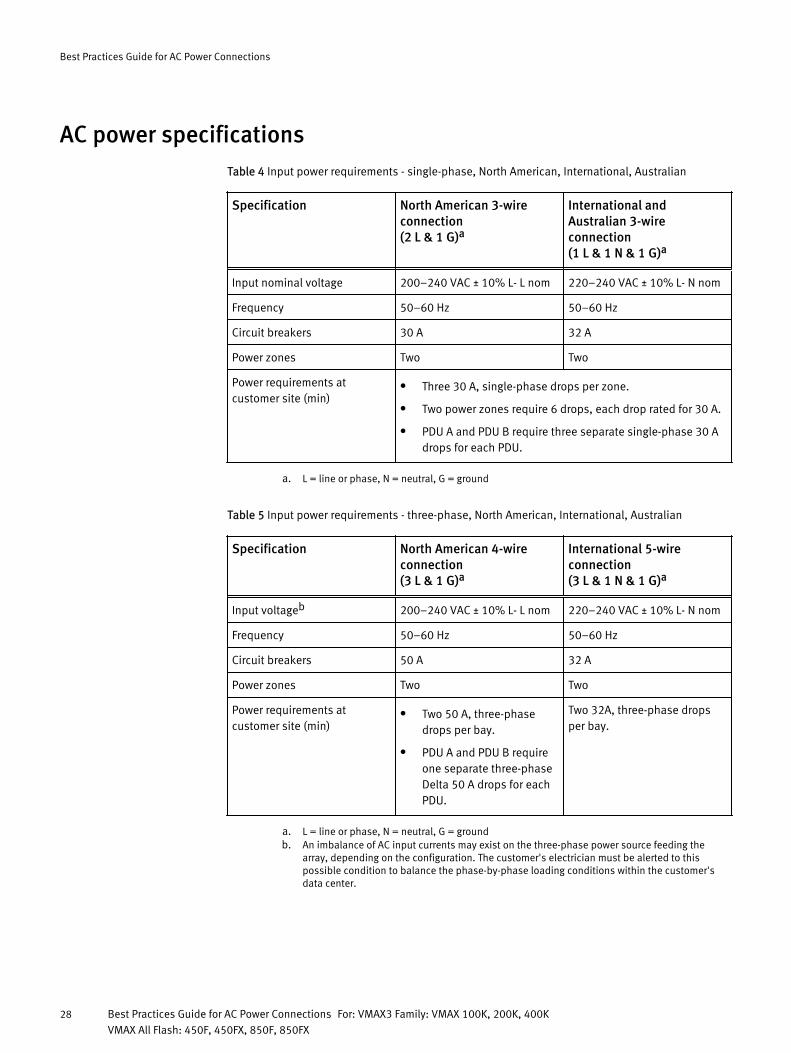
AC power specificationsTable 4 Input power requirements - single-phase, North American, International, Australian
Specification North American 3-wireconnection(2 L & 1 G)a
International andAustralian 3-wireconnection(1 L & 1 N & 1 G)a
Input nominal voltage 200–240 VAC ± 10% L- L nom 220–240 VAC ± 10% L- N nom
Frequency 50–60 Hz 50–60 Hz
Circuit breakers 30 A 32 A
Power zones Two Two
Power requirements atcustomer site (min)
l Three 30 A, single-phase drops per zone.
l Two power zones require 6 drops, each drop rated for 30 A.
l PDU A and PDU B require three separate single-phase 30 Adrops for each PDU.
a. L = line or phase, N = neutral, G = ground
Table 5 Input power requirements - three-phase, North American, International, Australian
Specification North American 4-wireconnection(3 L & 1 G)a
International 5-wireconnection(3 L & 1 N & 1 G)a
Input voltageb 200–240 VAC ± 10% L- L nom 220–240 VAC ± 10% L- N nom
Frequency 50–60 Hz 50–60 Hz
Circuit breakers 50 A 32 A
Power zones Two Two
Power requirements atcustomer site (min)
l Two 50 A, three-phasedrops per bay.
l PDU A and PDU B requireone separate three-phaseDelta 50 A drops for eachPDU.
Two 32A, three-phase dropsper bay.
a. L = line or phase, N = neutral, G = groundb. An imbalance of AC input currents may exist on the three-phase power source feeding the
array, depending on the configuration. The customer's electrician must be alerted to thispossible condition to balance the phase-by-phase loading conditions within the customer'sdata center.
Best Practices Guide for AC Power Connections
28 Best Practices Guide for AC Power Connections For: VMAX3 Family: VMAX 100K, 200K, 400KVMAX All Flash: 450F, 450FX, 850F, 850FX