
EMC TEST REPORT for Azlan Logistics Limited SP-1800P Pair ... · 2. EMI Test Receiver Rohde &...
27
Shenzhen Anbotek Compliance Laboratory Limited Page 1 of 27 Report No. R011605502Y Shenzhen Anbotek Compliance Laboratory Limited Tel:(86)755-26066544 Fax:(86)755-26014772 www.anbotek.com EMC TEST REPORT for Azlan Logistics Limited SP-1800P Pair 60w Active Loudspeakers Model No. : SP-1800P Report Number : R011605502Y Date of Test : May 01~04, 2016 Date of Report : May 04, 2016 Applicant : Azlan Logistics Limited Redwood 2, Chineham Business Park, Crockford Lane, Basingstoke, Hampshire, RG24 8WQ, United Kingdom Prepared By : Shenzhen Anbotek Compliance Laboratory Limited Address : 1/F., Building 1, SEC Industrial Park, No.0409 Qianhai Road, Nanshan District, Shenzhen, Guangdong, China Tel: (86) 755-26066544 Fax: (86) 755-26014772
Transcript of EMC TEST REPORT for Azlan Logistics Limited SP-1800P Pair ... · 2. EMI Test Receiver Rohde &...

Shenzhen Anbotek Compliance Laboratory LimitedPage 1 of 27 Report No. R011605502Y
Shenzhen Anbotek Compliance Laboratory LimitedTel:(86)755-26066544 Fax:(86)755-26014772 www.anbotek.com
EMC TEST REPORTfor
Azlan Logistics Limited
SP-1800P Pair 60w Active LoudspeakersModel No. : SP-1800P
Report Number : R011605502YDate of Test : May 01~04, 2016Date of Report : May 04, 2016
Applicant : Azlan Logistics LimitedRedwood 2, Chineham Business Park, Crockford Lane,Basingstoke, Hampshire, RG24 8WQ, United Kingdom
Prepared By : Shenzhen Anbotek Compliance Laboratory LimitedAddress : 1/F., Building 1, SEC Industrial Park, No.0409 Qianhai Road,
Nanshan District, Shenzhen, Guangdong, ChinaTel: (86) 755-26066544Fax: (86) 755-26014772

Shenzhen Anbotek Compliance Laboratory LimitedPage 2 of 27 Report No. R011605502Y
Shenzhen Anbotek Compliance Laboratory LimitedTel:(86)755-26066544 Fax:(86)755-26014772 www.anbotek.com
TABLE OF CONTENTS
Description Page
Test Report Verification1. GENERAL INFORMATION..................................................................................................... 4
1.1. Description of Device (EUT)............................................................................................................... 41.2. Description of Test Facility..................................................................................................................51.3. Measurement Uncertainty.................................................................................................................... 51.4. Test Summary.......................................................................................................................................5
2. MEASURING DEVICES AND TEST EQUIPMENT..............................................................62.1. Conducted Emission Measurement......................................................................................................62.2. Radiated Emission Test........................................................................................................................62.3.Disturbance Power Measurement..........................................................................................................6
3. POWER LINE CONDUCTED EMISSION TEST...................................................................73.1. Block Diagram of Test Setup............................................................................................................... 73.2. Measuring Standard..............................................................................................................................73.3. Power Line Conducted Emission Limits..............................................................................................73.4. EUT Configuration on Measurement...................................................................................................73.5. Operating Condition of EUT................................................................................................................73.6. Test Procedure......................................................................................................................................83.7. Measuring Results................................................................................................................................ 8
4. DISTURBANCE POWER TEST............................................................................................. 114.1. Block Diagram of Test Setup............................................................................................................. 114.2. Measuring Standard............................................................................................................................114.3. Disturbance Power Limits..................................................................................................................114.4. EUT Configuration on Measurement.................................................................................................114.5. Operating Condition of EUT..............................................................................................................114.6. Test Procedure....................................................................................................................................124.7. Disturbance Power Test Results.........................................................................................................12
5. RADIATED EMISSION TEST................................................................................................ 155.1. Block Diagram of Test....................................................................................................................... 155.2. Measuring Standard............................................................................................................................155.3. Radiated Emission Limits.................................................................................................................. 155.4. EUT Configuration on Test................................................................................................................165.5. Operating Condition of EUT..............................................................................................................165.6. Test Procedure....................................................................................................................................165.7. Measuring Results.............................................................................................................................. 16
6. PHOTOGRAPH.........................................................................................................................196.1. Photo of Power Line Conducted Emission Test.................................................................................196.2. Photo of Radiated Emission Test....................................................................................................... 196.3. Photo of Disturbance Power Test.......................................................................................................20APPENDIX I (Photos of EUT) (6 pages)


Shenzhen Anbotek Compliance Laboratory LimitedPage 4 of 27 Report No. R011605502Y
Shenzhen Anbotek Compliance Laboratory LimitedTel:(86)755-26066544 Fax:(86)755-26014772 www.anbotek.com
1. GENERAL INFORMATION
1.1. Description of Device (EUT)EUT : SP-1800P Pair 60w Active Loudspeakers
Model Number : SP-1800P
Test Power Supply : AC 240V, 50Hz
Applicant : Azlan Logistics LimitedRedwood 2, Chineham Business Park, Crockford Lane,Basingstoke, Hampshire, RG24 8WQ, United Kingdom
Manufacturer : Azlan Logistics LimitedAddress : Redwood 2, Chineham Business Park, Crockford Lane,
Basingstoke, Hampshire, RG24 8WQ, United Kingdom
Factory : Azlan Logistics LimitedAddress : Redwood 2, Chineham Business Park, Crockford Lane,
Basingstoke, Hampshire, RG24 8WQ, United Kingdom
Date of receipt : May 01, 2016
Date of Test : May 01~04, 2016

Shenzhen Anbotek Compliance Laboratory LimitedPage 5 of 27 Report No. R011605502Y
Shenzhen Anbotek Compliance Laboratory LimitedTel:(86)755-26066544 Fax:(86)755-26014772 www.anbotek.com
1.2.Description of Test FacilityThe test facility is recognized, certified, or accredited by the following organizations:
CNAS - LAB Code: L3503Shenzhen Anbotek Compliance Laboratory Limited., Laboratory has been assessedand in compliance with CNAS/CL01: 2006 accreditation criteria for testinglaboratories (identical to ISO/IEC 17025:2005 General Requirements) for theCompetence of Testing Laboratories.
FCC-Registration No.: 752021Shenzhen Anbotek Compliance Laboratory Limited, EMC Laboratory has beenregistered and fully described in a report filed with the (FCC) FederalCommunications Commission. The acceptance letter from the FCC is maintainedin our files. Registration 752021, July 10, 2013
IC-Registration No.: 8058A-1Shenzhen Anbotek Compliance Laboratory Limited., EMC Laboratory has beenregistered and fully described in a report filed with the (IC) Industry Canada.The acceptance letter from the IC is maintained in our files. Registration8058A-1, Feb. 22, 2013
Test LocationAll Emissions tests were performed:Shenzhen Anbotek Compliance Laboratory Limited. at 1/F., Building 1, SECIndustrial Park, No.0409 Qianhai Road, Nanshan District, Shenzhen, Guangdong,China
1.3. Measurement UncertaintyRadiation Uncertainty : Ur = 4.1dB (Horizontal)
Ur = 4.3dB (Vertical)
Conduction Uncertainty : Uc =3.4dB
1.4. Test SummaryFor the EUT described above. The standards used were AS/NZS CISPR 13:2012.Tests Carried Out Under AS/NZS CISPR 13:2012
Standard Test Items Status
AS/NZS CISPR 13:2012 Power Line Conducted Emission Test(150kHz To 30MHz)
√
AS/NZS CISPR 13:2012 Power disturbance(30MHz To 300MHz) √
AS/NZS CISPR 13:2012 Radiated Emission Test(FM)(30MHz To 300MHz)
√
√ Indicates that the test is applicablex Indicates that the test is not applicable

Shenzhen Anbotek Compliance Laboratory LimitedPage 6 of 27 Report No. R011605502Y
Shenzhen Anbotek Compliance Laboratory LimitedTel:(86)755-26066544 Fax:(86)755-26014772 www.anbotek.com
2. MEASURING DEVICES AND TEST EQUIPMENTTest equipments list of Shenzhen Anbotek Compliance Laboratory Limited.
2.1. Conducted Emission MeasurementItem Equipment Manufacturer Model No. Serial No. Last Cal. Cal. Interval
1. Two-LineV-network Rohde & Schwarz ENV216 100055 Apr. 17, 2016 1 Year
2. EMI Test Receiver Rohde & Schwarz ESCI 100627 Apr. 17, 2016 1 Year
3. RF Switching Unit ComplianceDirection RSU-M2 38303 Apr. 17, 2016 1 Year
2.2. Radiated Emission TestItem Equipment Manufacturer Model No. Serial No. Last Cal. Cal. Interval1. EMI Test Receiver Rohde & Schwarz ESPI 101604 Apr. 17, 2016 1 Year2. Bilog Broadband
Antenna Schwarzbeck VULB9163 VULB9163-289 Apr. 20, 2016 1 Year
3. Pre-amplifier SONOMA 310N 186860 Apr. 17, 2016 1 Year
2.3.Disturbance Power MeasurementItem Equipment Manufacturer Model No. Serial No. Last Cal. Cal. Interval1. Absorbing Clamp FCC F-201-23M
M 08166 Apr. 17, 2015 1 Year
2. EMI Test Receiver Rohde & Schwarz ESCI 100627 Apr. 17, 2015 1 Year3. RF Switching Unit Compliance
Direction RSU-M2 38303 Apr. 17, 2015 1 Year
Shenzhen Anbotek Compliance Laboratory LimitedPage 7 of 27 Report No. R011605502Y
Shenzhen Anbotek Compliance Laboratory LimitedTel:(86)755-26066544 Fax:(86)755-26014772 www.anbotek.com
3. POWER LINE CONDUCTED EMISSION TEST
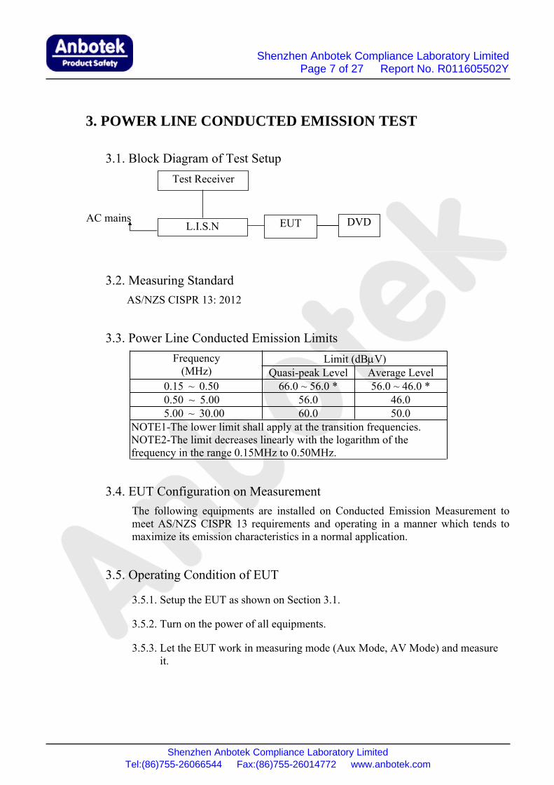
3.1. Block Diagram of Test Setup
3.2. Measuring StandardAS/NZS CISPR 13: 2012
3.3. Power Line Conducted Emission LimitsFrequency(MHz)
Limit (dBμV)Quasi-peak Level Average Level
0.15 ~ 0.50 66.0 ~ 56.0 * 56.0 ~ 46.0 *0.50 ~ 5.00 56.0 46.05.00 ~ 30.00 60.0 50.0
NOTE1-The lower limit shall apply at the transition frequencies.NOTE2-The limit decreases linearly with the logarithm of thefrequency in the range 0.15MHz to 0.50MHz.
3.4. EUT Configuration on MeasurementThe following equipments are installed on Conducted Emission Measurement tomeet AS/NZS CISPR 13 requirements and operating in a manner which tends tomaximize its emission characteristics in a normal application.
3.5. Operating Condition of EUT
3.5.1. Setup the EUT as shown on Section 3.1.
3.5.2. Turn on the power of all equipments.
3.5.3. Let the EUT work in measuring mode (Aux Mode, AV Mode) and measureit.
DVDEUTL.I.S.NAC mains
Test Receiver
Shenzhen Anbotek Compliance Laboratory LimitedPage 8 of 27 Report No. R011605502Y
Shenzhen Anbotek Compliance Laboratory LimitedTel:(86)755-26066544 Fax:(86)755-26014772 www.anbotek.com
3.6. Test ProcedureThe EUT is put on the plane 0.8m high above the ground by insulating support andconnected to the AC mains through Line Impedance Stability Network (L.I.S.N).This provided a 50ohm coupling impedance for the tested equipments. Both sidesof AC line are investigated to find out the maximum conducted emission accordingto the AS/NZS CISPR 13 regulations during conducted emission measurement.
The bandwidth of the field strength meter (R&S Test Receiver ESCI) is set at9KHz in 150KHz~30MHz.
The frequency range from 150kHz to 30MHz is investigated for AC mains.
The test results are listed in Section 3.7.
3.7. Measuring ResultsPASS.
The frequency range 150kHz to 30MHz is investigated
The test curves are shown in the following pages.
The EUT was tested on (Aux Mode, AV Mode) modes,only the worst data of (AVMode) are attached in the following pages.
Shenzhen Anbotek Compliance Laboratory LimitedPage 9 of 27 Report No. R011605502Y
Shenzhen Anbotek Compliance Laboratory LimitedTel:(86)755-26066544 Fax:(86)755-26014772 www.anbotek.com
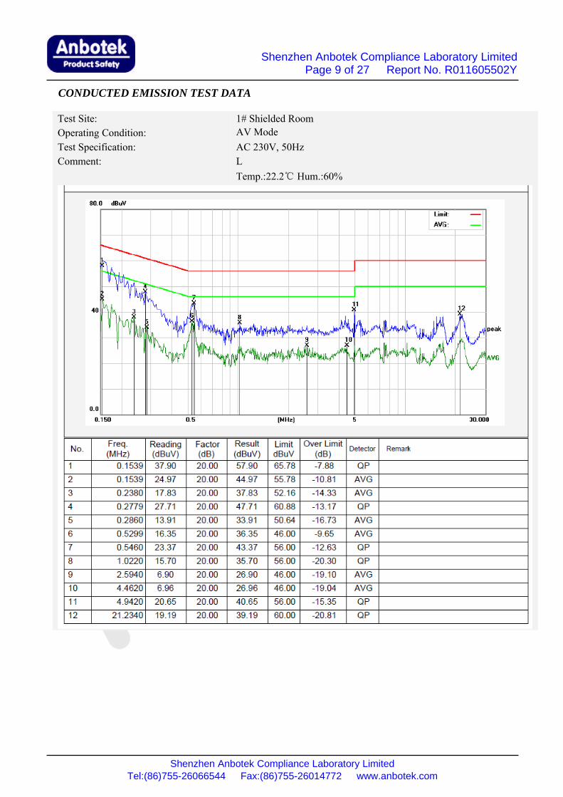
CONDUCTED EMISSION TEST DATA
Test Site: 1# Shielded RoomOperating Condition: AV ModeTest Specification: AC 230V, 50HzComment: L
Temp.:22.2℃ Hum.:60%

Shenzhen Anbotek Compliance Laboratory LimitedPage 10 of 27 Report No. R011605502Y
Shenzhen Anbotek Compliance Laboratory LimitedTel:(86)755-26066544 Fax:(86)755-26014772 www.anbotek.com
CONDUCTED EMISSION TEST DATA
Test Site: 1# Shielded RoomOperating Condition: AV ModeTest Specification: AC 230V, 50HzComment: N
Temp.:22.2℃ Hum.:60%
Shenzhen Anbotek Compliance Laboratory LimitedPage 11 of 27 Report No. R011605502Y
Shenzhen Anbotek Compliance Laboratory LimitedTel:(86)755-26066544 Fax:(86)755-26014772 www.anbotek.com
4. DISTURBANCE POWER TEST
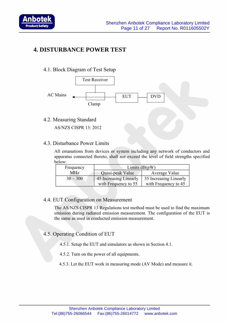
4.1. Block Diagram of Test Setup
Clamp
4.2. Measuring StandardAS/NZS CISPR 13: 2012
4.3. Disturbance Power LimitsAll emanations from devices or system including any network of conductors andapparatus connected thereto, shall not exceed the level of field strengths specifiedbelow:
FrequencyMHz
Limits dB(pW)Quasi-peak Value Average Value
30 ~ 300 45 Increasing Linearlywith Frequency to 55
35 Increasing Linearlywith Frequency to 45
4.4. EUT Configuration on MeasurementThe AS/NZS CISPR 13 Regulations test method must be used to find the maximumemission during radiated emission measurement. The configuration of the EUT isthe same as used in conducted emission measurement.
4.5. Operating Condition of EUT
4.5.1. Setup the EUT and simulators as shown in Section 4.1.
4.5.2. Turn on the power of all equipments.
4.5.3. Let the EUT work in measuring mode (AV Mode) and measure it.
EUTAC Mains
Test Receiver
DVD

Shenzhen Anbotek Compliance Laboratory LimitedPage 12 of 27 Report No. R011605502Y
Shenzhen Anbotek Compliance Laboratory LimitedTel:(86)755-26066544 Fax:(86)755-26014772 www.anbotek.com
4.6. Test ProcedureThe EUT is placed on the ground and away from other metallic surface at least0.8m. It is connected to the power mains through an extension cord of 6m min. Theabsorber clamp clamps the cord and moves from the far end to the EUT to measurethe disturbing energy emitted from the cord.
The bandwidth of the test receiver(R&S ESCI) is set at 120kHz.
All the test results are listed in Section 4.7.
4.7. Disturbance Power Test ResultsPASS.
The frequency spectrum from 30 MHz to 300 MHz is investigated.
The test curves are shown in the following pages.

Shenzhen Anbotek Compliance Laboratory LimitedPage 13 of 27 Report No. R011605502Y
Shenzhen Anbotek Compliance Laboratory LimitedTel:(86)755-26066544 Fax:(86)755-26014772 www.anbotek.com
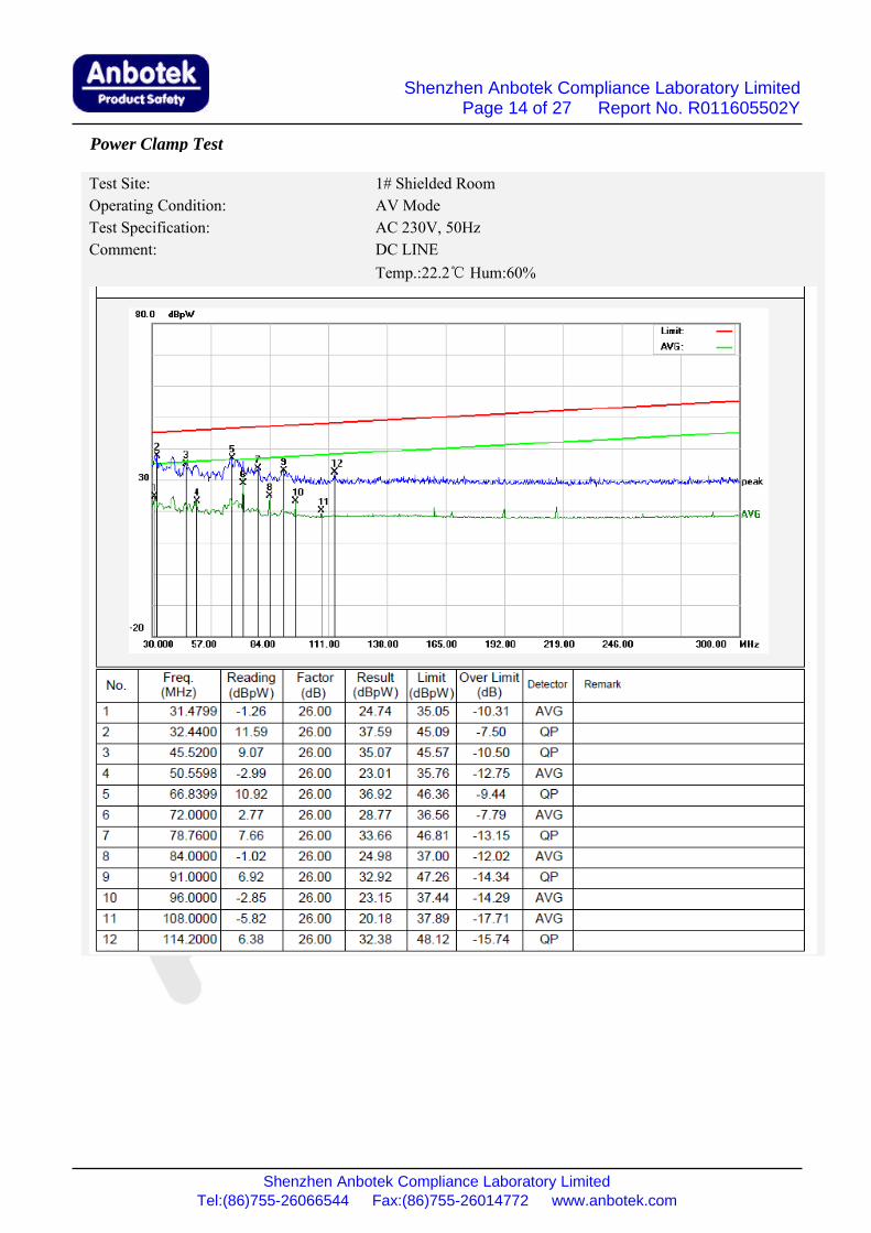
Power Clamp Test
Test Site: 1# Shielded RoomOperating Condition: AV ModeTest Specification: AC 230V, 50HzComment: AC LINE
Temp.:22.2℃ Hum:60%
Shenzhen Anbotek Compliance Laboratory LimitedPage 14 of 27 Report No. R011605502Y
Shenzhen Anbotek Compliance Laboratory LimitedTel:(86)755-26066544 Fax:(86)755-26014772 www.anbotek.com
Power Clamp Test
Test Site: 1# Shielded RoomOperating Condition: AV ModeTest Specification: AC 230V, 50HzComment: DC LINE
Temp.:22.2℃ Hum:60%

Shenzhen Anbotek Compliance Laboratory LimitedPage 15 of 27 Report No. R011605502Y
Shenzhen Anbotek Compliance Laboratory LimitedTel:(86)755-26066544 Fax:(86)755-26014772 www.anbotek.com
5. RADIATED EMISSION TEST
5.1. Block Diagram of Test
5.1.1. Block diagram of connection between the EUT and simulators
5.1.2. Block diagram of test setup (In chamber)
5.2. Measuring StandardAS/NZS CISPR 13: 2012
5.3. Radiated Emission Limits5.3.1. AS/NZS CISPR 13: 2012
Radiated Emission LimitsAll emanations from an AS/NZS CISPR 13 device or system, including anynetwork of conductors and apparatus connected thereto, shall not exceed thelevel of field strengths specified below:
ANTENNA ELEVATION VARIES FROM 1 TO4 METERS
DVEUTAC Mains
3 MetersEUT System
0.8 Meter
GROUND PLANE

Shenzhen Anbotek Compliance Laboratory LimitedPage 16 of 27 Report No. R011605502Y
Shenzhen Anbotek Compliance Laboratory LimitedTel:(86)755-26066544 Fax:(86)755-26014772 www.anbotek.com
Note: (1) The smaller limit shall apply at the combination pointbetween two frequency bands.
(2) Distance refers to the distance in meters between themeasuring instrument antenna and the closed point of any partof the EUT.
5.4. EUT Configuration on TestThe AS/NZS CISPR 13 regulations test method must be used to find themaximum emission during radiated emission measurement.
5.5. Operating Condition of EUT
5.5.1. Turn on the power.
5.5.2. Let the EUT work in measuring mode (Aux Mode, AV Mode) andmeasure it.
5.6. Test ProcedureThe EUT is placed on a turn table which is 0.8 meter high above the ground. Theturn table can rotate 360 degrees to determine the position of the maximumemission level. The EUT is set 3 meters away from the receiving antenna which ismounted on a antenna tower. The antenna can be moved up and down from 1 to 4meters to find out the maximum emission level. Bilog antenna is used as areceiving antenna. Both horizontal and vertical polarization of the antenna are seton test.
The bandwidth of the Receiver (ESCI) is set at 120kHz.
The EUT is tested in 9*6*6 Chamber.
The test results are listed in Section 5.7.
5.7. Measuring ResultsPASS.
The frequency range from 30MHz to 1000MHz is investigated.
The test curves are shown in the following pages.
The EUT was tested on (Aux Mode, AV Mode) modes,only the worst data of (AVMode) are attached in the following pages.
FREQUENCYMHz
DISTANCEMeters
Limit ValuesdB(μV)/m
≤1000 3 Fundamental 5730~300 3 Harmonics 52300~1000 3 Harmonics 5630~230 3 Other 40230~1000 3 Other 47
Shenzhen Anbotek Compliance Laboratory LimitedPage 17 of 27 Report No. R011605502Y
Shenzhen Anbotek Compliance Laboratory LimitedTel:(86)755-26066544 Fax:(86)755-26014772 www.anbotek.com
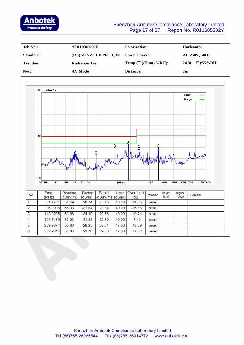
Job No.: AT011605500E Polarization: Horizontal
Standard: (RE)AS/NZS CISPR 13_3m Power Source: AC 230V, 50Hz
Test item: Radiation Test Temp.(℃)/Hum.(%RH): 24.3( ℃)/55%RH
Note: AV Mode Distance: 3m

Shenzhen Anbotek Compliance Laboratory LimitedPage 18 of 27 Report No. R011605502Y
Shenzhen Anbotek Compliance Laboratory LimitedTel:(86)755-26066544 Fax:(86)755-26014772 www.anbotek.com
Job No.: AT011605500E Polarization: Vertical
Standard: (RE)AS/NZS CISPR 13_3m Power Source: AC 230V, 50Hz
Test item: Radiation Test Temp.(C)/Hum.(%RH): 24.3( C)/55%RH
Note: AV Mode Distance: 3m
Shenzhen Anbotek Compliance Laboratory LimitedPage 19 of 27 Report No. R011605502Y
Shenzhen Anbotek Compliance Laboratory LimitedTel:(86)755-26066544 Fax:(86)755-26014772 www.anbotek.com
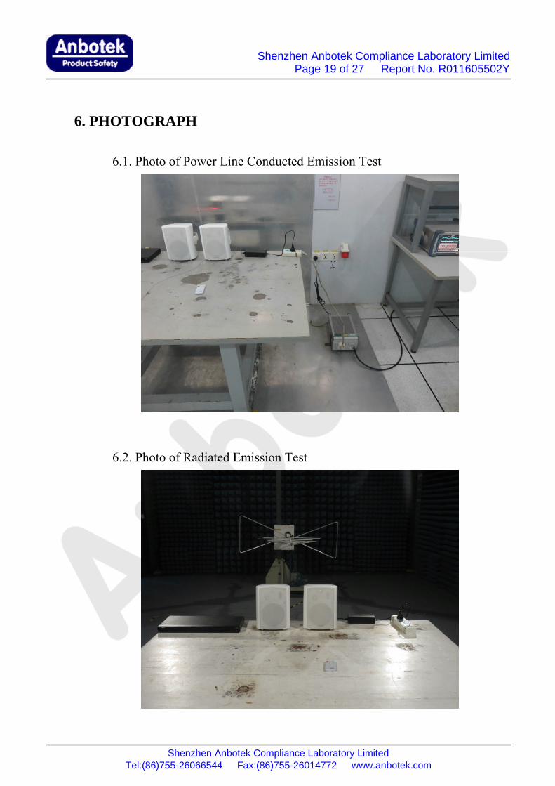
6. PHOTOGRAPH
6.1. Photo of Power Line Conducted Emission Test
6.2. Photo of Radiated Emission Test
Shenzhen Anbotek Compliance Laboratory LimitedPage 20 of 27 Report No. R011605502Y
Shenzhen Anbotek Compliance Laboratory LimitedTel:(86)755-26066544 Fax:(86)755-26014772 www.anbotek.com
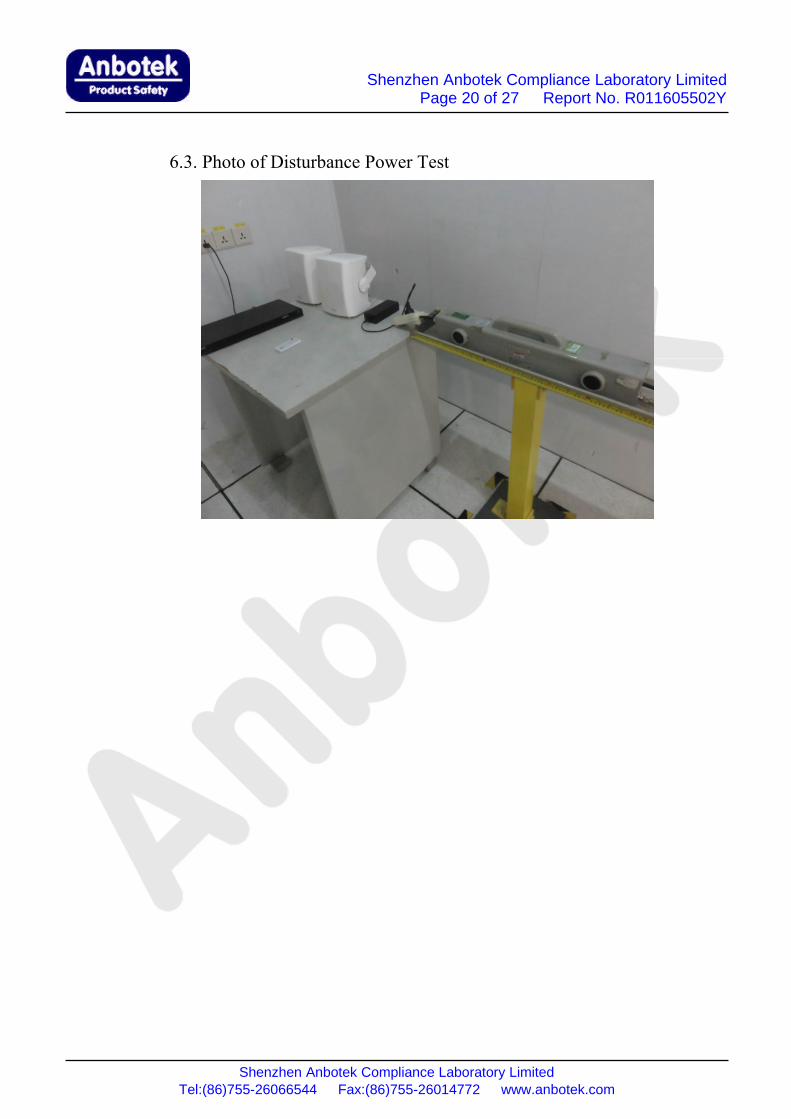
6.3. Photo of Disturbance Power Test

Shenzhen Anbotek Compliance Laboratory LimitedPage 21 of 27 Report No. R011605502Y
Shenzhen Anbotek Compliance Laboratory LimitedTel:(86)755-26066544 Fax:(86)755-26014772 www.anbotek.com
APPENDIX I(Photos of EUT)

Shenzhen Anbotek Compliance Laboratory LimitedPage 22 of 27 Report No. R011605502Y
Shenzhen Anbotek Compliance Laboratory LimitedTel:(86)755-26066544 Fax:(86)755-26014772 www.anbotek.com
Figure 1The EUT- Overall View
Figure 2The EUT- Front View

Shenzhen Anbotek Compliance Laboratory LimitedPage 23 of 27 Report No. R011605502Y
Shenzhen Anbotek Compliance Laboratory LimitedTel:(86)755-26066544 Fax:(86)755-26014772 www.anbotek.com
Figure 3The EUT- Back View
Figure 4The EUT- Side View

Shenzhen Anbotek Compliance Laboratory LimitedPage 24 of 27 Report No. R011605502Y
Shenzhen Anbotek Compliance Laboratory LimitedTel:(86)755-26066544 Fax:(86)755-26014772 www.anbotek.com
Figure 5The EUT- Partial View
Figure 6The EUT- Partial View

Shenzhen Anbotek Compliance Laboratory LimitedPage 25 of 27 Report No. R011605502Y
Shenzhen Anbotek Compliance Laboratory LimitedTel:(86)755-26066544 Fax:(86)755-26014772 www.anbotek.com
Figure 7The EUT- Inside View
Figure 8The EUT- Inside View

Shenzhen Anbotek Compliance Laboratory LimitedPage 26 of 27 Report No. R011605502Y
Shenzhen Anbotek Compliance Laboratory LimitedTel:(86)755-26066544 Fax:(86)755-26014772 www.anbotek.com
Figure 9The EUT- Inside View
Figure 10The EUT- Remote Control View

Shenzhen Anbotek Compliance Laboratory LimitedPage 27 of 27 Report No. R011605502Y
Shenzhen Anbotek Compliance Laboratory LimitedTel:(86)755-26066544 Fax:(86)755-26014772 www.anbotek.com
Figure 11The EUT- Adapter View


![Dma td 100627[2]](https://static.fdocuments.us/doc/165x107/54d6bf814a795928048b457a/dma-td-1006272.jpg)