
EMC TEST REPORT - apc.com · 1. Test Receiver Rohde & Schwarz ESCI 101152 Mar. 08, 2017 1 Year 2....
72
Dongguan Nore Testing Center Co., Ltd. Report No.: NTC1712651EV00 Page 1 of 72 EMC TEST REPORT The device described below is tested by Dongguan Nore Testing Center Co., Ltd. to determine the maximum emission levels emanating from the device, the severe levels which the device can endure and E.U.T.’s performance criterion. The test results are contained in this test report. Dongguan Nore Testing Center Co., Ltd. is assumed of full responsibility for the accuracy and completeness of these tests. Applicant/Manufacturer : American Power Conversion Holding Inc., Taiwan Branch Address : 3F., No.205, Sec. 3, Beixin Rd., Xindian Dist. New Taipei City 231 Taiwan Factory : VOLTRONIC POWER TECHNOLOGY CORP. Address : 1-4F, Building 5, YuSheng Industrial Park, No.467, Section Xixiang, National Highway 107, Xixiang, Bao An District, Shenzhen 518102, P.R. China E.U.T. : UPS Brand Name : or Model No. : ab2KcIe(For variables a, b, c, and e see the report on page 9 ) Measurement Standard : EN 62040-2: 2006+AC: 2006 EN 61000-3-2: 2014, EN 61000-3-3: 2013, (EN 61000-4-2: 2009, EN 61000-4-3: 2006+A2: 2010, EN 61000-4-4: 2012, EN 61000-4-5: 2014, EN 61000-4-6: 2014, EN 61000-4-8: 2010, EN 61000-4-11: 2004, EN 61000-2-2: 2002) Date of Receiver : December 07, 2017 Date of Test : December 08, 2017 to December 12, 2017 Date of Report : December 15, 2017 This Test Report is Issued Under the Authority of : Prepared by Approved & Authorized Signer Bowen Zhu / Engineer Iori Fan / Manager This report shows that the E.U.T. is technically compliant with the EN 62040-2,EN 61000-3-3 and EN 61000-3-2. This report applies to above tested sample only and shall not be reproduced in part without written approval of Dongguan Nore Testing Center Co., Ltd. TEL: +86-769-22022444 FAX: +86-769-22022799 Web: www.ntc-c.com Address: Building D, Gaosheng Science & Technology Park, Zhouxi Longxi Road, Nancheng District, Dongguan City, Guangdong, China
-
Upload
vuongthuan -
Category
Documents
-
view
218 -
download
0
Transcript of EMC TEST REPORT - apc.com · 1. Test Receiver Rohde & Schwarz ESCI 101152 Mar. 08, 2017 1 Year 2....

Dongguan Nore Testing Center Co., Ltd.
Report No.: NTC1712651EV00
Page 1 of 72
EMC TEST REPORT
The device described below is tested by Dongguan Nore Testing Center Co., Ltd. to determine the maximum emission
levels emanating from the device, the severe levels which the device can endure and E.U.T.’s performance criterion. The
test results are contained in this test report. Dongguan Nore Testing Center Co., Ltd. is assumed of full responsibility for
the accuracy and completeness of these tests.
Applicant/Manufacturer : American Power Conversion Holding Inc., Taiwan Branch
Address : 3F., No.205, Sec. 3, Beixin Rd., Xindian Dist. New Taipei City 231 Taiwan
Factory : VOLTRONIC POWER TECHNOLOGY CORP.
Address : 1-4F, Building 5, YuSheng Industrial Park, No.467, Section Xixiang, National Highway 107, Xixiang, Bao An District, Shenzhen 518102, P.R. China
E.U.T. : UPS
Brand Name :
or
Model No. : ab2KcIe(For variables a, b, c, and e see the report on page 9 )
Measurement Standard : EN 62040-2: 2006+AC: 2006
EN 61000-3-2: 2014, EN 61000-3-3: 2013,
(EN 61000-4-2: 2009, EN 61000-4-3: 2006+A2: 2010,
EN 61000-4-4: 2012, EN 61000-4-5: 2014, EN 61000-4-6: 2014,
EN 61000-4-8: 2010, EN 61000-4-11: 2004, EN 61000-2-2: 2002)
Date of Receiver : December 07, 2017
Date of Test : December 08, 2017 to December 12, 2017
Date of Report : December 15, 2017
This Test Report is Issued Under the Authority of :
Prepared by Approved & Authorized Signer
Bowen Zhu / Engineer Iori Fan / Manager
This report shows that the E.U.T. is technically compliant with the EN 62040-2,EN 61000-3-3 and EN 61000-3-2. This report
applies to above tested sample only and shall not be reproduced in part without written approval of Dongguan Nore Testing
Center Co., Ltd.
TEL: +86-769-22022444 FAX: +86-769-22022799 Web: www.ntc-c.com
Address: Building D, Gaosheng Science & Technology Park, Zhouxi Longxi Road, Nancheng District,
Dongguan City, Guangdong, China

Dongguan Nore Testing Center Co., Ltd.
Report No.: NTC1712651EV00
Page 2 of 72
TABLE OF CONTENTS
1. SUMMARY OF TEST RESULTS ............................................... 6
2. GENERAL INFORMATION .................................................... 7
2.1 Details of E.U.T. .................................................................. 7
2.2 Description of Support Device ...................................................... 9
2.3 Block Diagram of Test Setup ....................................................... 9
2.4 Test Facility ..................................................................... 10
2.5 Abnormalities from Standard Conditions ............................................ 10
3. MEASURING DEVICES AND TEST EQUIPMENT ............................... 11
3.1 For Mains terminals Disturbance voltage Test ....................................... 11
3.2 For Radiated Emission Measurement ............................................... 11
3.3 For Harmonic Measurement/ Flicker Measurement ................................... 11
3.4 For Electrostatic Discharge Immunity Test........................................... 12
3.5 For RF Electromagnetic Field Immunity Test ......................................... 12
3.6 For Electrical Fast Transient /Burst Immunity Test .................................... 12
3.7 For Surge Immunity Test .......................................................... 12
3.8 For Injected Currents Immunity Measurement ....................................... 12
3.9 For Magnetic Field Immunity Measurement .......................................... 12
3.10 For Low Frequency Signal Immunity Test .......................................... 13
3.11 For Voltage Dips and Interruptions Measurement ................................... 13
4. MAINS TERMINAL DISTURBANCE VOLTAGE MEASUREMENT ................. 14
4.1. Block Diagram of Test Setup ...................................................... 14
4.2. Limit of Mains Terminal Disturbance voltage measurement ........................... 14
4.3. Test Procedure ................................................................. 15
4.4. Operating Condition of E.U.T. ..................................................... 15
4.5. Mains Terminal Disturbance Voltage Test Results ................................... 15
5. RADIATED EMISSION MEASUREMENT ....................................... 20
5.1 Block Diagram of Test ............................................................ 20
5.2 Limit of Radiated Emission Measurement ........................................... 20
5.3 Test Procedure .................................................................. 21
5.4 Operating Condition of E.U.T. ..................................................... 21
5.5 Radiated Emission Measurement Result ............................................ 21
6.HARMONIC CURRENT EMISSION TEST ....................................... 26
6.1 Block Diagram of Test Setup ...................................................... 26
6.2 Limits of Harmonics current measurement .......................................... 26
6.3 Test Procedure .................................................................. 27
6.4 Operating Condition of E.U.T. ..................................................... 27
6.5 Test Results ..................................................................... 27
7.VOLTAGE FLUCTUATIONS & FLICKER TEST ................................. 31
7.1 Block Diagram of Test Setup ...................................................... 31
7.2 Limits of Voltage Fluctuations & Flicker Measurement ................................ 31
7.3 Test Procedure .................................................................. 31
7.4 Operating Condition of E.U.T. ..................................................... 32
7.5 Test Results ..................................................................... 32

Dongguan Nore Testing Center Co., Ltd.
Report No.: NTC1712651EV00
Page 3 of 72
8.PERFORMANCE CRITERIA FOR IMMUNITY ................................... 34
9.LOW FREQUENCY SIGNALS TEST ........................................... 35
9.1 Block Diagram of Test Setup ...................................................... 35
9.2 Test Standard and Performance Criterion ........................................... 35
9.3 Operating Condition of E.U.T. ..................................................... 35
9.4 Test Results ..................................................................... 35
10.ELECTROSTATIC DISCHARGE TEST ........................................ 37
10.1 Block Diagram of Test Setup ..................................................... 37
10.2 Test Standard and Severity Levels ................................................ 37
10.3 Test Procedure ................................................................. 38
10.4 Test Results ................................................................... 38
11.RF FIELD STRENGTH SUSCEPTIBILITY TEST ................................ 40
11.1 Block Diagram of Test Setup ..................................................... 40
11.2 Test Standard and Severity Levels ................................................ 40
11.3 Test Procedure ................................................................. 41
11.4 Test Results ................................................................... 41
12.ELECTRICAL FAST TRANSIENT/BURST TEST ................................ 43
12.1 Block Diagram of Test Setup ..................................................... 43
12.2 Test Standard and Severity Levels ................................................ 43
12.3 Test Procedure ................................................................. 44
12.4 Test Result .................................................................... 44
13. SURGE IMMUNITY TEST ................................................... 46
13.1Block Diagram of Test Setup ...................................................... 46
13.2 Test Standard and Severity Levels ................................................ 46
13.3 Test Procedure ................................................................. 47
13.4 Test Result .................................................................... 47
14. INJECTED CURRENTS SUSCEPTIBILITY TEST .............................. 49
13.1 Block Diagram of Test Setup ..................................................... 49
14.2 Test Standard and Severity Levels ................................................ 49
14.3 Test Procedure ................................................................. 50
14.4 Test Result .................................................................... 50
15.VOLTAGE DIPS AND INTERRUPTIONS TEST ................................. 52
15.1 Block Diagram of Test Setup ..................................................... 52
15.2 Test Standard and Severity Levels ................................................ 52
15.3 Test Procedure ................................................................. 52
15.4 Test Result .................................................................... 53
16.MAGNETIC FIELD IMMUNITY TEST .......................................... 55
16.1 Block Diagram of Test Setup ..................................................... 55
16.2 Test Standard and Severity Levels ................................................ 55
16.3 Test Procedure ................................................................. 56
16.4 Test Result .................................................................... 56
17.PHOTOGRAPH ............................................................ 58
17.1 Photo of Conducted Emission Measurement ....................................... 58
17.2 Photo of Radiation Emission Measurement ......................................... 58
Dongguan Nore Testing Center Co., Ltd.
Report No.: NTC1712651EV00
Page 4 of 72
17.3 Photo of Harmonic Measurement ................................................. 59
17.4 Photo of Electrostatic Discharge Test .............................................. 59
17.5 Photo of Electrical Fast Transient /Surge /Dips Test ................................. 60
Appendix I (Photos of E.U.T.) (11 pages)
Dongguan Nore Testing Center Co., Ltd.
Report No.: NTC1712651EV00
Page 5 of 72
Revision History of This Test Report
Report Number Description Issued Date
NTC1712651EV00 Initial Issue 2017-12-15

Dongguan Nore Testing Center Co., Ltd.
Report No.: NTC1712651EV00
Page 6 of 72
1. SUMMARY OF TEST RESULTS
The E.U.T. has been tested according to the following specifications:
EMISSION
Standard Test Type Result Remarks
EN 62040-2: 2006+AC: 2006
Mains Terminal Disturbance Voltage Test PASS Uncertainty: 2.7dB
Radiated Emission Test PASS Uncertainty: 3.4dB
EN 61000-3-2: 2014 Harmonic current emission
PASS Meets the Requirements.
EN 61000-3-3: 2013 Voltage fluctuations &flicker
PASS Meets the requirements.
IMMUNITY(EN 62040-2: 2006+AC: 2006)
Standard Test Type Result Remarks
EN 61000-2-2: 2002 Low frequency signals test PASS Meets the requirements of Performance Criterion A
EN 61000-4-2: 2009 Electrostatic discharge immunity test
PASS Meets the requirements of Performance Criterion B
EN 61000-4-3: 2006+A2: 2010
Radiated, radio-frequency, electromagnetic field immunity test
PASS Meets the requirements of Performance Criterion A
EN 61000-4-4: 2012 Electrical fast transient/ burst immunity test
PASS Meets the requirements of Performance Criterion B
EN 61000-4-5: 2014 Surge immunity test PASS Meets the requirements of Performance Criterion B
EN 61000-4-6: 2014 Injected Currents immunity test
PASS Meets the requirements of Performance Criterion A
EN 61000-4-8: 2010 Magnetic Field immunity test
PASS Meets the requirements of Performance Criterion A
EN 61000-4-11: 2004 Voltage Dips and Interruptions
PASS Meets the requirements of Performance Criterion B

Dongguan Nore Testing Center Co., Ltd.
Report No.: NTC1712651EV00
Page 7 of 72
2. GENERAL INFORMATION
2.1 Details of E.U.T.
E.U.T. : UPS
Model No. : ab2KcIe(For variables a, b, c, and e see the report on page 9)
WARNING : This is a category C2 Uninterruptible Power Supply product. In a residential environment, this product may cause radio interference, in which case the user may be required to take additional measures.
Brand Name : or
Rating : Input: 220-240Vac; 50-60Hz; 10A max Output: 220-240Vac; 50-60Hz; 9.1A max; Capacity: 2000VA/1600W
Test Voltage : AC 230V 50Hz, DC 48V Internal battery
Cable : None
Description of model difference
: See the page 8 for details
Remark : None

Dongguan Nore Testing Center Co., Ltd.
Report No.: NTC1712651EV00
Page 8 of 72
Model differences:

Dongguan Nore Testing Center Co., Ltd.
Report No.: NTC1712651EV00
Page 9 of 72
2.2 Description of Support Device
None
2.3 Block Diagram of Test Setup
Block diagram of connection between the E.U.T. and simulators
(1) Normal operation mode(Full Load)
(2) Stored energy operation mode(Full Load)
AC Mains EUT Load
EUT Load

Dongguan Nore Testing Center Co., Ltd.
Report No.: NTC1712651EV00
Page 10 of 72
2.4 Test Facility
2.5 Abnormalities from Standard Conditions
None
Site Description EMC Lab : Listed by CNAS, November 02, 2016
The certificate is valid until August 15, 2018 The Laboratory has been assessed and proved to be in compliance with CNAS/CL01 The Certificate Registration Number is L5795. Listed by FCC, July 03, 2014 The Certificate Number is 665078. Listed by Industry Canada, June 08, 2017 The Certificate Registration Number. Is 46405-9743
Name of Firm : Dongguan Nore Testing Center Co., Ltd. (Dongguan NTC Co., Ltd.)
Site Location : Building D, Gaosheng Science & Technology Park, Zhouxi Longxi Road, Nancheng District, Dongguan City, Guangdong Province, China

Dongguan Nore Testing Center Co., Ltd.
Report No.: NTC1712651EV00
Page 11 of 72
3. MEASURING DEVICES AND TEST EQUIPMENT
3.1 For Mains terminals Disturbance voltage Test
Item Equipment Manufacturer Model No. Serial No. Last Cal. Cal. Interval
1. Test Receiver Rohde & Schwarz ESCI 101152 Mar. 08, 2017 1 Year
2. L.I.S.N Rohde & Schwarz ENV 216 101317 Mar. 08, 2017 1 Year
3. L.I.S.N Schwarzbeck NNLK8129 8129-212 Mar. 22, 2017 1 Year
4. RF Switching Unit
Compliance Direction Systems Inc.
RSU-M2 38311 Mar. 08, 2017 1 Year
5. Pulse Limiter MTS-systemtechnik MTS-IMP-136 26115-010-0007
Mar. 08, 2017 1 Year
3.2 For Radiated Emission Measurement
Item Equipment Manufacturer Model No. Serial No. Last Cal. Cal. Interval
1. Test Receiver Rohde & Schwarz ESCI7 100837 Mar. 08, 2017 1 Year
2. Antenna Schwarzbeck VULB9162 9162-010 Mar. 22, 2017 1 Year
3. Positioning Controller
UC UC 3000 N/A N/A N/A
4. Color Monitor SUNSPO SP-140A N/A N/A N/A
5. Single Phase Power Line Filter
SAEMC PF201A-32 110210 N/A N/A
6. 3 Phase Power Line Filter
SAEMC PF401A-200 110318 N/A N/A
7. DC Power Filter SAEMC PF301A-200 110245 N/A N/A
8. Cable Huber+Suhner CBL3-NN-9M 21490001 Mar. 08, 2017 1 Year
9. Cable Huber+Suhner CIL02 N/A Mar. 08, 2017 1 Year
10. Power Amplifier HP HP 8447D 1145A00203 Mar. 08, 2017 1 Year
3.3 For Harmonic Measurement/ Flicker Measurement
Item Equipment Manufacturer Model No. Serial No. Last Cal. Cal. Interval
1. Power Frequency Test System
California Instruments
CTS 72846 Mar. 08, 2017 1 Year
2. Software California Instruments
CTS30 N/A N/A N/A

Dongguan Nore Testing Center Co., Ltd.
Report No.: NTC1712651EV00
Page 12 of 72
3.4 For Electrostatic Discharge Immunity Test
Item Equipment Manufacturer Model No. Serial No. Last Cal. Cal. Interval
1. ESD Tester TESEQ NSG 437 432 Mar. 22, 2017 1 Year
3.5 For RF Electromagnetic Field Immunity Test
Item Equipment Manufacturer Model No. Serial No. Last Cal. Cal. Interval
1. RF Power Meter ESE 4242 13984 Nov. 04, 2017 1 Year
2. Power Amplifier TESEQ CBA 1G-150 T44029 N/A 1 Year
3. Signal Generator Agilent N5181A
MY50142530
Nov. 01, 2017 1 Year
4. Power Sensor ESE 51011EMC 35716 Nov. 04, 2017 1 Year
5. Antenna Schwarzbeck VULB9162 9162-010 Mar. 22, 2017 1 Year
3.6 For Electrical Fast Transient /Burst Immunity Test
Item Equipment Manufacturer Model No. Serial No. Last Cal. Cal. Interval
1. Burst Tester EM TEST UCS 500N V1104108683 Mar. 08, 2017 1 Year
2. Coupling Clamp EM TEST HFK 0311-94 Mar. 08, 2017 1 Year
3. Test Soft EM TEST lec. control N/A N/A N/A
3.7 For Surge Immunity Test
Item Equipment Manufacturer Model No. Serial No. Last Cal. Cal. Interval
1. Surge Tester EM TEST UCS 500N V1104108683 Mar. 08, 2017 1 Year
2. Test Soft EM TEST lec. control N/A N/A N/A
3.8 For Injected Currents Immunity Measurement
Item Equipment Manufacturer Model No. Serial No. Last Cal. Cal. Interval
1. C/S Test System
HAEFELY WinPAMP NSEMC002 N/A N/A
2. CDN FRANNOKIA CDN-M2+M3 A2210150 Mar. 22, 2017 1 Year
3.9 For Magnetic Field Immunity Measurement
Item Equipment Manufacturer Model No. Serial No. Last Cal. Cal. Interval
1. Magnetic Field Tester
HAEFELY MAG100.1 150579 Oct.18, 2017 1 Year
2. Test Software
N/A N/A N/A N/A N/A

Dongguan Nore Testing Center Co., Ltd.
Report No.: NTC1712651EV00
Page 13 of 72
3.10 For Low Frequency Signal Immunity Test
Item Equipment Manufacturer Model No. Serial No. Last Cal. Cal. Interval
1. Programmable AC Source
CHROMA 6530 N/A Sep. 01, 2017 1 Year
3.11 For Voltage Dips and Interruptions Measurement
Item Equipment Manufacturer Model No. Serial No. Last Cal. Cal. Interval
1. Dips Tester EM TEST UCS500N V1104108683 Mar. 08, 2017 1 Year
2. Test Soft EM TEST lec.control N/A N/A N/A
3. Dips Modulator
EM TEST V4780S2 0111-11 Mar. 08, 2017 1 Year

Dongguan Nore Testing Center Co., Ltd.
Report No.: NTC1712651EV00
Page 14 of 72
4. MAINS TERMINAL DISTURBANCE VOLTAGE MEASUREMENT
4.1.Block Diagram of Test Setup
4.2.Limit of Mains Terminal Disturbance voltage measurement
Test Standard: EN 62040-2 Category C2
Limits of mains terminal interference voltage frequency range 0.15 MHz to 30 MHz for Category C2 Uninterruptible Power Supply equipment.
Frequency range MHz
Limits
(dBV)
Quasi-peak Average
0.15 to 0.50a 79 66
0.50 to 5b 73 60
5 to 30 73 60 a
The limit decreases linearly with the logarithm of the frequency. b
The lower limit shall apply at the transition frequency.
EUT Test Receiver
L.I.S.N
80cm
40cm
80cm
80cm
Power Source
Ground Reference Plane
Dongguan Nore Testing Center Co., Ltd.
Report No.: NTC1712651EV00
Page 15 of 72
4.3.Test Procedure
The E.U.T. is put on the 0.8 m high table and connected to the AC mains through a Artificial Mains Network (AMN). This provided a 50ohm coupling impedance for the tested equipments. Both sides of AC line are checked to find out the maximum conducted emission levels according to the EN 62040-2 regulations during conducted emission test. The bandwidth of the test receiver (R&S Test Receiver ESCI) is set at 9 KHz.
4.4.Operating Condition of E.U.T.
4.4.1 Setup the E.U.T. and simulators as shown in Section 2.3.
4.4.2 Turn on the power of all equipments.
4.4.3 Let the E.U.T. work in test modes (Normal operation mode, Stored energy operation mode) and test it.
4.5.Mains Terminal Disturbance Voltage Test Results
PASS. Please refer to the following pages.

Dongguan Nore Testing Center Co., Ltd.
Report No.: NTC1712651EV00
Page 16 of 72
E.U.T : UPS Model Name : ab2KcIe
Temperature : 26°C Relative Humidity : 55 %
Pressure : 1006 hPa Test Voltage : DC 48V
Test Mode : Stored energy operation mode Phase: Line

Dongguan Nore Testing Center Co., Ltd.
Report No.: NTC1712651EV00
Page 17 of 72
E.U.T : UPS Model Name : ab2KcIe
Temperature : 26°C Relative Humidity : 55 %
Pressure : 1006 hPa Test Voltage : DC 48V
Test Mode : Stored energy operation mode Phase: Neutral

Dongguan Nore Testing Center Co., Ltd.
Report No.: NTC1712651EV00
Page 18 of 72
E.U.T : UPS Model Name : ab2KcIe
Temperature : 26°C Relative Humidity : 55 %
Pressure : 1006 hPa Test Voltage : AC 230V/50Hz
Test Mode : Normal operation mode Phase: Neutral

Dongguan Nore Testing Center Co., Ltd.
Report No.: NTC1712651EV00
Page 19 of 72
E.U.T : UPS Model Name : ab2KcIe
Temperature : 26°C Relative Humidity : 55 %
Pressure : 1006 hPa Test Voltage : AC 230V/50Hz
Test Mode : Normal operation mode Phase: Line

Dongguan Nore Testing Center Co., Ltd.
Report No.: NTC1712651EV00
Page 20 of 72
5. RADIATED EMISSION MEASUREMENT
5.1 Block Diagram of Test
5.2 Limit of Radiated Emission Measurement
Test Standard: EN 62040-2 Category C2
Limits for radiated disturbance at a measuring distance of 3m
Frequency range
MHz
Quasi-peak limits dB(uV/m)
Category C1 Category C2 Category C3
30 to 230 40 50 60
230 to 1000 47 57 70
Note: The lower limit shall apply at the transition frequency.
Absorbing material
1m to 4m
3m EUT
0.8m
Pre Amplifier
Spectrum Analyzer
Antenna Tower
Ground Reference Plane
Ground Reference Plane
Turntable

Dongguan Nore Testing Center Co., Ltd.
Report No.: NTC1712651EV00
Page 21 of 72
5.3 Test Procedure
E.U.T. and its simulators are placed on a turntable, which is 0.8 meter high above ground. The turntable can rotate 360 degrees to determine the position of the maximum emission level. E.U.T. is set 3.0 meters away from the receiving antenna, which is mounted on a antenna tower. The antenna can be moved up and down between 1.0 meter and 4 meters to find out the maximum emission level. Broadband antenna (calibrated bilog antenna) is used as receiving antenna. Both horizontal and vertical polarization of the antenna is set on measurement. In order to find the maximum emission levels, all of the interface cables must be manipulated according to EN 62040-2 on radiated emission measurement. The bandwidth of the EMI test receiver (R&S ESCI7) is set at 120 KHz. The frequency range from 30 MHz to 1000 MHz is checked.
5.4 Operating Condition of E.U.T.
5.4.1 Setup the E.U.T. and simulators as shown in Section 2.3.
5.4.2 Turn on the power of all equipments.
5.4.3 Let the E.U.T. work in test modes (Normal operation mode, Stored energy operation mode) and test it.
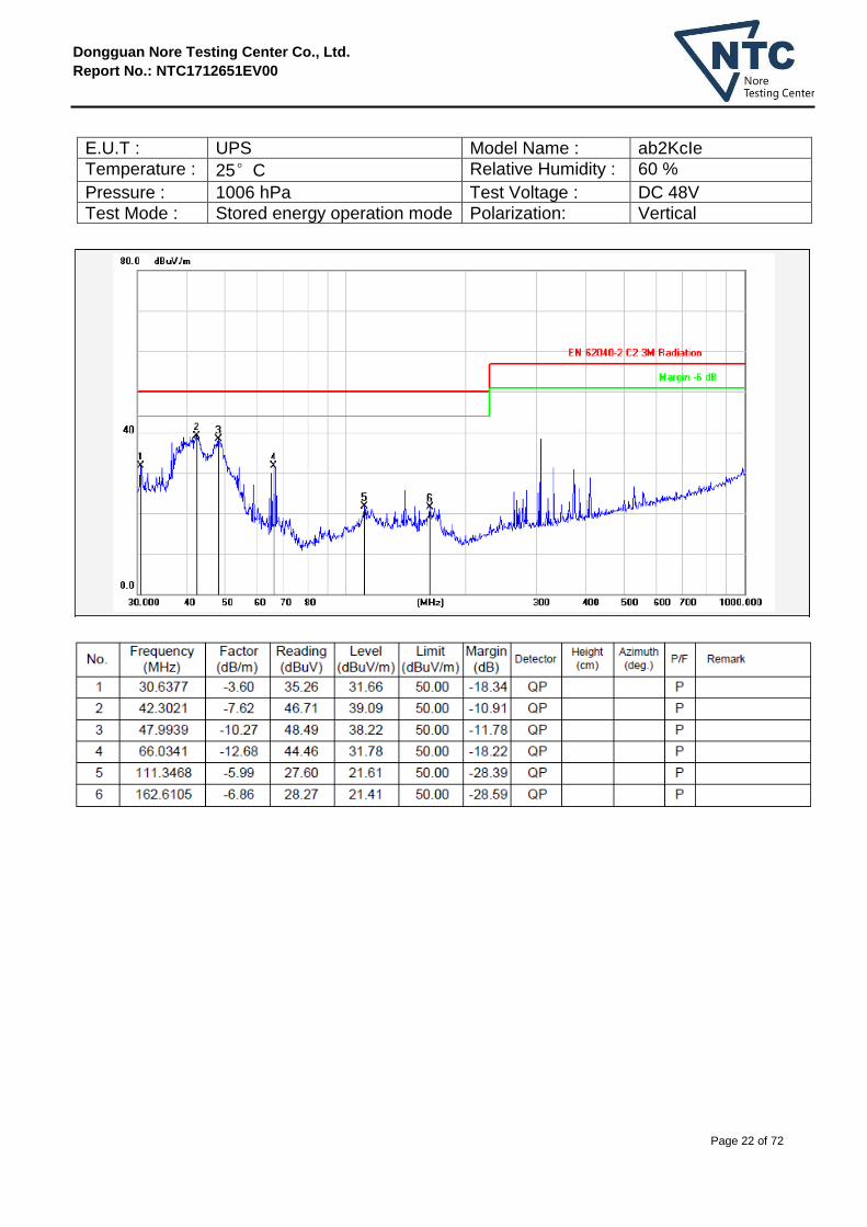
5.5 Radiated Emission Measurement Result
PASS.
Please refer to the following pages.
Dongguan Nore Testing Center Co., Ltd.
Report No.: NTC1712651EV00
Page 22 of 72
E.U.T : UPS Model Name : ab2KcIe
Temperature : 25°C Relative Humidity : 60 %
Pressure : 1006 hPa Test Voltage : DC 48V
Test Mode : Stored energy operation mode Polarization: Vertical

Dongguan Nore Testing Center Co., Ltd.
Report No.: NTC1712651EV00
Page 23 of 72
E.U.T : UPS Model Name : ab2KcIe
Temperature : 25°C Relative Humidity : 60 %
Pressure : 1006 hPa Test Voltage : DC 48V
Test Mode : Stored energy operation mode Polarization: Horizontal

Dongguan Nore Testing Center Co., Ltd.
Report No.: NTC1712651EV00
Page 24 of 72
E.U.T : UPS Model Name : ab2KcIe
Temperature : 25°C Relative Humidity : 60 %
Pressure : 1006 hPa Test Voltage : AC 230V/50Hz
Test Mode : Normal operation mode Polarization: Horizontal

Dongguan Nore Testing Center Co., Ltd.
Report No.: NTC1712651EV00
Page 25 of 72
E.U.T : UPS Model Name : ab2KcIe
Temperature : 25°C Relative Humidity : 60 %
Pressure : 1006 hPa Test Voltage : AC 230V/50Hz
Test Mode : Normal operation mode Polarization: Vertical

Dongguan Nore Testing Center Co., Ltd.
Report No.: NTC1712651EV00
Page 26 of 72
6.HARMONIC CURRENT EMISSION TEST
6.1 Block Diagram of Test Setup
6.2 Limits of Harmonics current measurement
Test Standard: EN 61000-3-2: 2014
Limits for Class A equipment Limits for Class D equipment
Harmonics Order
n
Max. permissible harmonics current
A
Harmonics Order
n
Max. permissible harmonics current
per watt mA/W
Max. permissible harmonics current
A
Odd harmonics
3 2.30 3 3.4 2.30
5 1.14 5 1.9 1.14
7 0.77 7 1.0 0.77
9 0.40 9 0.5 0.40
11 0.33 11 0.35 0.33
13 0.21 13 0.30 0.21
15<=n<=39 0.15×15/n 15<=n<=39 3.85/n 0.15×15/n
Even harmonics
2 1.08
4 0.43
6 0.30
8<=n<=40 0.23×8/n
For the following categories of equipment limits are not specified in this edition of the standard. Note 1: Equipment with a rated power of 75W or less, other than lighting equipment.
Power frequency test system
EUT
0.8m
Ground Reference Plane
Dongguan Nore Testing Center Co., Ltd.
Report No.: NTC1712651EV00
Page 27 of 72
6.3 Test Procedure
The E.U.T. was put on the top of a wooden table 0.8m above the ground and operated to produce the maximum harmonic components under normal operating conditions for each successive harmonic component in turn. The E.U.T. is classified as follows:
Class A: Balanced three-phase equipment, Household appliances excluding equipment as Class D, Tools excluding portable tools, Dimmers for incandescent lamps, audio equipment ,equipment not specified in one of the three other classes.
Class B: Portable tools; Arc welding equipment which is not professional equipment.
Class C: Lighting equipment.
Class D: Equipment having a specified power less than or equal to 600W of the following types: Personal computers and personal computer monitors and television receivers.
6.4 Operating Condition of E.U.T.
6.4.1 Setup the E.U.T. and simulators as shown in Section 2.3.
6.4.2 Turn on the power of all equipments.
6.4.3 Let the E.U.T. work in test mode (Normal operation mode) and test it.
6.5 Test Results
PASS. Please refer to the following pages.

Dongguan Nore Testing Center Co., Ltd.
Report No.: NTC1712651EV00
Page 28 of 72
Harmonics – Class-A per Ed. 3.2 (2009)(Run time)
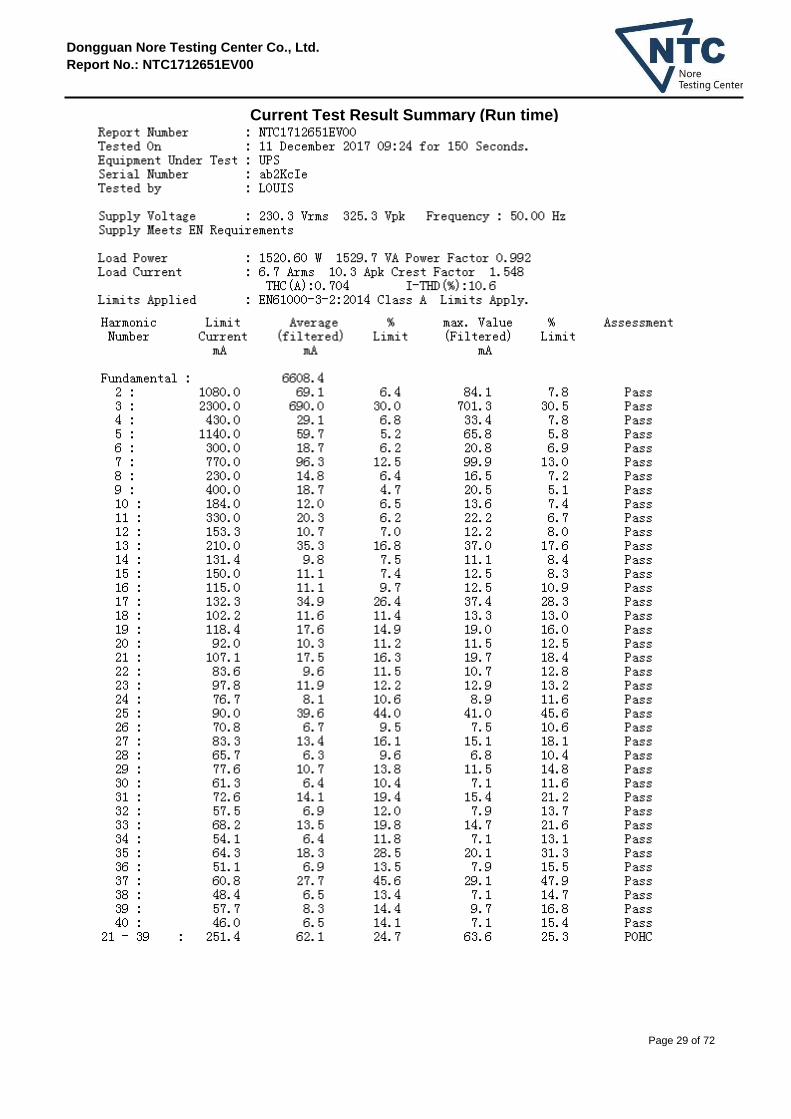
Report Number : NTC1712651EV00 Tested On : 11 December 2017 9:24 for 150 Seconds. Equipment Under Test : UPS Serial Number : ab2KcIe Tested by : LOUIS Current & voltage waveforms
Harmonics and Class A limit line European Limits
Dongguan Nore Testing Center Co., Ltd.
Report No.: NTC1712651EV00
Page 29 of 72
Current Test Result Summary (Run time)

Dongguan Nore Testing Center Co., Ltd.
Report No.: NTC1712651EV00
Page 30 of 72
Voltage Source Verification Data (Run time)

Dongguan Nore Testing Center Co., Ltd.
Report No.: NTC1712651EV00
Page 31 of 72
7.VOLTAGE FLUCTUATIONS & FLICKER TEST
7.1 Block Diagram of Test Setup
7.2 Limits of Voltage Fluctuations & Flicker Measurement
Test Standard: EN 61000-3-3: 2013
Test Item Limit
Pst (Short-term flicker indicator.) 1.0
Plt (Long-term flicker indicator.) 0.65
Td(t)(ms) ( Maximum time that d(t) exceeds 3.3%) 500
dmax(%) (Maximum relative voltage change.) 4
dc(%) (Relative steady-state voltage change) 3.3
7.3 Test Procedure
The E.U.T. was put on the top of a wooden table 0.8m above the ground and operated to produce the most unfavorable sequence of voltage changes under normal operating conditions.

Dongguan Nore Testing Center Co., Ltd.
Report No.: NTC1712651EV00
Page 32 of 72
7.4 Operating Condition of E.U.T.
7.4.1 Setup the E.U.T. and simulators as shown in Section 2.3.
7.4.2 Turn on the power of all equipments.
7.4.3 Let the E.U.T. work in test mode(Normal operation mode) and test it.
7.5 Test Results
PASS. Please refer to the following pages.

Dongguan Nore Testing Center Co., Ltd.
Report No.: NTC1712651EV00
Page 33 of 72
Flicker Test Summary per EN/IEC61000-3-3 Ed. 3.0 (2013) (Run time)

Dongguan Nore Testing Center Co., Ltd.
Report No.: NTC1712651EV00
Page 34 of 72
8.PERFORMANCE CRITERIA FOR IMMUNITY
The performance criteria are referred to the test standard: EN 62040-2 Performance criteria for immunity tests
Criterion A Criterion B
Output characteristics
Voltage permitted to vary only within the steady-state characteristics applicable(100m sec limits in Figures 1,2 or 3 of IEC62040-3)
Voltage permitted to vary within the inverse time characteristics applicable (<100 m sec limits in Figures 1, 2 or 3 of IEC 62040-3)
External and internal indications and metering
Change only during test Change only during test
Control signals to external devices
No change Change only temporarily in consistency with the actual Uninterruptible Power Supply mode of operation
Mode of operation No change Change only temporarily
The tests shall be made with the Uninterruptible Power Supply in the following
conditions: ---- rated input voltage; ---- normal mode of operation; ---- linear load at rated active output power or at light load according to
IEC62040-3.

Dongguan Nore Testing Center Co., Ltd.
Report No.: NTC1712651EV00
Page 35 of 72
9.LOW FREQUENCY SIGNALS TEST
9.1 Block Diagram of Test Setup
9.2 Test Standard and Performance Criterion
EN 62040-2: 2006+AC: 2006 Category C2 (EN 61000-2-2: 2002)
Performance criterion: A
9.3 Operating Condition of E.U.T.
9.3.1 Setup the E.U.T. and simulators as shown in Section 2.3.
9.3.2 Turn on the power of all equipments.
9.3.3 Let the E.U.T. work in test mode (Normal operation mode) and test it.
9.4 Test Results
PASS.
Please refer to following page.
Load

Dongguan Nore Testing Center Co., Ltd.
Report No.: NTC1712651EV00
Page 36 of 72
Low Frequency Signals Test Result
Ambient Condition: Temp.: 22 ℃ R.H.: 52 % Air Pressure: 101 kPa
Power Supply: AC 230V 50Hz Required Performance Criterion: A
Tested mode: Normal operation mode
Frequency Range (Hz)
Position Strength Result (Performance Criterion)
140
See Fig.1
10V(rms) Sinusoidal
A
160 A
200 A
240 A
280 A
320 A
360 A Note:
Test Equipment: 1. Isolation transformer
Primary: Secondary=1:1 2. Signal Generator
AC Source: 6530(CHROMA)
Test Engineer : Sance

Dongguan Nore Testing Center Co., Ltd.
Report No.: NTC1712651EV00
Page 37 of 72
10.ELECTROSTATIC DISCHARGE TEST
10.1 Block Diagram of Test Setup
10.2 Test Standard and Severity Levels
10.2.1 Test Standard: EN 62040-2: 2006+AC: 2006 Category C2 (EN 61000-4-2: 2009 Air Discharge: Severity Level: 3, ± 8KV; Contact Discharge: Level: 2, ± 4KV)
10.2.2 Severity Levels:
Performance criterion: B
Level Test Voltage Contact Discharge (KV)
Test Voltage Air Discharge (KV)
1. ±2 ±2
2. ±4 ±4
3. ±6 ±8
4. ±8 ±15
X Special Special
470KΩ
470KΩ
ESD Gun
ESD Generator
VCP 0.5m×0.5m
EUT
0.1m
0.8m
HCP
Ground Reference Plane (GRP)

Dongguan Nore Testing Center Co., Ltd.
Report No.: NTC1712651EV00
Page 38 of 72
10.3 Test Procedure
10.3.1 Air Discharge:
This test is done on a non-conductive surface. The round discharge tip of the discharge electrode shall be approached as fast as possible to touch the E.U.T.. After each discharge, the discharge electrode shall be removed from the E.U.T.. The generator is then re-triggered for a new single discharge and repeated 10 times for each pre-selected test point. This procedure shall be repeated until all the air discharge completed
10.3.2 Contact Discharge:
All the procedure shall be same as Section 10.3.1. except that the tip of the discharge electrode shall touch the E.U.T..
10.3.3 Indirect discharge for horizontal coupling plane
At least 10 single discharges(in the most sensitive polarity) shall be applied at the front edge of each HCP opposite the center point of each unit(if applicable) of the E.U.T. and 0.1m from the front of the E.U.T.. The long axis of the discharge electrode shall be in the plane of the HCP and perpendicular to its front edge during the discharge.
10.3.4 Indirect discharge for vertical coupling plane
At least 10 single discharge (in the most sensitive polarity) shall be applied to the center of one vertical edge of the coupling plane. The coupling plane, of dimensions 0.5m X 0.5m, is placed parallel to, and positioned at a distance of 0.1m from the E.U.T.. Discharges shall be applied to the coupling plane, with this plane in sufficient different positions that the four faces of the E.U.T. are completely illuminated.
10.4 Test Results
PASS. Please refer to the following page.

Dongguan Nore Testing Center Co., Ltd.
Report No.: NTC1712651EV00
Page 39 of 72
Electrostatic Discharge Test Results
Ambient Condition: Temp.: 22 ℃ R.H.: 52 % Air Pressure: 101 kPa
Power Supply: AC 230V 50Hz, DC 48V
Required Performance Criterion: B
Test Specifications: 2, 4 kV Contact Discharge; 2, 4, 8 kV Air Discharge
For each point positive 10 times and negative 10 times
Tested mode: Normal operation mode, Stored energy operation mode
Test Point
Kind A-Air Discharge
C-Contact Discharge
Result (Performance Criterion)
Screen A A
Button A A
Slot A A
Metal C A
Screw C A
Port C A
Indirect Discharge
(HCP)
C A
Indirect Discharge
(VCP)
C A
Note:
Test Equipment : ESD Tester (TESEQ, NSG 437) Test Engineer : Sance

Dongguan Nore Testing Center Co., Ltd.
Report No.: NTC1712651EV00
Page 40 of 72
11.RF FIELD STRENGTH SUSCEPTIBILITY TEST
11.1 Block Diagram of Test Setup
11.2 Test Standard and Severity Levels
11.2.1 Test Standard EN 62040-2: 2006+AC: 2006 Category C2 (EN 61000-4-3: 2006+A2: 2010, Severity Level: 3, 10V / m)
11.2.2 Severity Levels
Performance Criterion : A
Level Field Strength V/m
1. 1
2. 3
3. 10
X Special
Dongguan Nore Testing Center Co., Ltd.
Report No.: NTC1712651EV00
Page 41 of 72
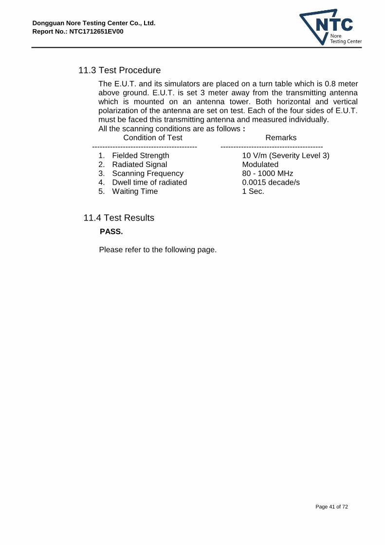
11.3 Test Procedure
The E.U.T. and its simulators are placed on a turn table which is 0.8 meter above ground. E.U.T. is set 3 meter away from the transmitting antenna which is mounted on an antenna tower. Both horizontal and vertical polarization of the antenna are set on test. Each of the four sides of E.U.T. must be faced this transmitting antenna and measured individually.
All the scanning conditions are as follows : Condition of Test Remarks ----------------------------------------- ----------------------------------------
1. Fielded Strength 10 V/m (Severity Level 3) 2. Radiated Signal Modulated 3. Scanning Frequency 80 - 1000 MHz 4. Dwell time of radiated 0.0015 decade/s 5. Waiting Time 1 Sec.
11.4 Test Results
PASS.
Please refer to the following page.

Dongguan Nore Testing Center Co., Ltd.
Report No.: NTC1712651EV00
Page 42 of 72
RF Field Strength Susceptibility Test Results
Ambient Condition: Temp.: 22 ℃ R.H.: 52% Air Pressure: 101 kPa
Power Supply: AC 230V 50Hz, DC 48V
Required Performance Criterion: A
Test Specifications: Modulation: 1kHz, 80%AM; Step Size: 1%; Dwell Time: 1s
Tested mode: Normal operation mode, Stored energy operation mode
Frequency (MHz) Level
(V/m) Antenna polarity Side
Result (Performance
Criterion)
80-1000 10
Horizontal
Front A
Left A
Right A
Back A
Vertical
Front A
Left A
Right A
Back A
Note:
Test Equipment : 1. Signal Generator : N5181A (Agilent) 2. Power Amplifier : CBA 1G-150 (TESEQ) 3. Log.-Per. Antenna: VULB9162 (SCHWARZBECK) 4. RF Power Meter. Dual Channel : 4242 (ESE) 5. Power Sensor: 51011EMC (ESE) Test Engineer : Sance

Dongguan Nore Testing Center Co., Ltd.
Report No.: NTC1712651EV00
Page 43 of 72
12.ELECTRICAL FAST TRANSIENT/BURST TEST
12.1 Block Diagram of Test Setup
12.2 Test Standard and Severity Levels
12.2.1 Test Standard EN 62040-2: 2006+AC: 2006 Category C2 (EN 61000-4-4: 2012, Severity Level, Level 4: 4KV)
12.2.2 Severity level
Performance Criterion : B
Open circuit output test voltage and repetition rate of the impulses
Level On power port, PE
On I/O (Input/Output) Signal data and control ports
Voltage peak KV
Repetition rate KHz
Voltage peak KV
Repetition rate KHz
1. 0.5 5 or 100 0.25 5 or 100 2. 1.0 5 or 100 0.5 5 or 100 3. 2.0 5 or 100 1.0 5 or 100 4. 4.0 5 or 100 2.0 5 or 100 X Special Special Special Special
Note 1 Use of 5 KHz repetition rates is traditional; however, 100 KHz is closer
to reality. Product committees should determine which frequencies are relevant for specific products or product types.
Note 2 With some products, there may be no clear distinction, between power ports and I/O ports, in which case it is up to product committees to make this determination for test purposes.
Note 3 “X” is an open level. The level has to be specified in the dedicated equipment specification.
EFT/B Test
EUT
0.5m
0.8m
0.1m Insulating Support
Ground Reference Plane
Ground Reference Plane

Dongguan Nore Testing Center Co., Ltd.
Report No.: NTC1712651EV00
Page 44 of 72
12.3 Test Procedure
The E.U.T. is put on the table which is 0.8 meter high above the ground. This reference ground plane shall project beyond the E.U.T. by at least 0.1m on all sides and the minimum distance between E.U.T. and all other conductive structure, except the ground plane beneath the E.U.T., shall be more than 0.5m.
12.3.1 For input and output AC power ports:
The E.U.T. is connected to the power mains by using a coupling device which couples the EFT interference signal to AC power lines. Both polarities of the test voltage should be applied during compliance test and the duration of the test is 2 minutes.
12.3.2 For signal lines ports:
It’s unnecessary to test.
12.3.3 For DC ports:
It’s unnecessary to test.
12.4 Test Result
PASS.
Please refer to the following page.

Dongguan Nore Testing Center Co., Ltd.
Report No.: NTC1712651EV00
Page 45 of 72
Electrical Fast Transient/Burst Test Results
Ambient Condition: Temp.: 22 ℃ R.H.: 52 % Air Pressure: 101 kPa
Power Supply: AC 230V 50Hz Required Performance Criterion: B
Test Specifications: Repetition Frequency: 5kHz; Duration: 15ms; Period: 300ms
Test mode: Normal operation mode
Line : AC Mains Coupling : Direct
Signal line Capacitive
DC line
Line (Input and output AC
power ports) Test Voltage
Result (Performance Criterion)
L ±4KV A
N ±4KV A
PE ±4KV A
L、N ±4KV A
L、PE ±4KV A
N、PE ±4KV A
L、N、PE ±4KV A
Signal line --- ---
DC line --- ---
Note :
Test Equipment : Burst Tester(EM TEST, UCS500N) Test Engineer : Sance

Dongguan Nore Testing Center Co., Ltd.
Report No.: NTC1712651EV00
Page 46 of 72
13. SURGE IMMUNITY TEST
13.1Block Diagram of Test Setup
13.2 Test Standard and Severity Levels
13.2.1 Test Standard EN 62040-2: 2006+AC: 2006 Category C2 (EN 61000-4-5: 2014, Severity Level: Line To Line, Level *: 6.0KV; Line To Earth, Level *: 6.0KV
13.2.2 Severity level
Performance Criterion : B
Severity Level Open-Circuit Test Voltage KV
1 2 3 4 *
0.5 1.0 2.0 4.0
Special
Surge Tester
EUT
Ground Reference Plane(GRP)
0.8m

Dongguan Nore Testing Center Co., Ltd.
Report No.: NTC1712651EV00
Page 47 of 72
13.3 Test Procedure
1. Set up the E.U.T. and test generator as shown on Section 12.1. 2. For line to line coupling mode, provide a 6.0KV 1.2/50us voltage
surge (at open-circuit condition) and 8/20us current surge to E.U.T. selected points.
3. At least 5 positive and 5 negative (polarity) tests with a maximum 1/min repetition rate are conducted during test.
4. Different phase angles are done individually. 5. Record the E.U.T. operating situation during compliance test and
decide the E.U.T. immunity criterion for above each test.
13.4 Test Result
PASS.
Please refer to the following page.

Dongguan Nore Testing Center Co., Ltd.
Report No.: NTC1712651EV00
Page 48 of 72
Surge Immunity Test Results
Ambient Condition: Temp.: 22 ℃ R.H.: 52 % Air Pressure: 101 kPa
Power Supply: AC 230V 50Hz Required Performance Criterion: B
Test Specifications: Voltage surge 1.2/50 us ; Current surge 8/20 us ; Five positive and five negative pulses each at 0°, 90°, 180° and 270°.
Test mode: Normal operation mode
Line(AC Input) Phase Angle Test Voltage Result
(Performance Criterion)
L-N 0°, 90°, 180°, 270° ±6.0KV A
L-PE 0°, 90°, 180°, 270° ±6.0KV A
N-PE 0°, 90°, 180°, 270° ±6.0KV A
Signal line --- --- ---
DC line --- --- ---
Note :
Test Equipment : Surge Tester(EM TEST, UCS500N) Test Engineer : Sance

Dongguan Nore Testing Center Co., Ltd.
Report No.: NTC1712651EV00
Page 49 of 72
14. INJECTED CURRENTS SUSCEPTIBILITY TEST
14.1Block Diagram of Test Setup
14.2 Test Standard and Severity Levels
14.2.1 Test Standard EN 62040-2: 2006+AC: 2006 Category C2 (EN 61000-4-6: 2014, Severity Level 3: 10V (rms), 0.15MHz ~ 80MHz)
14.2.2 Severity level
Performance Criterion : A
Level Field Strength V
1. 1 2. 3
3. 10
X Special
CDN
Power Amplifier
Signal
Generator
EUT
0.1m Insulating Support
Ground Reference Plane(GRP)

Dongguan Nore Testing Center Co., Ltd.
Report No.: NTC1712651EV00
Page 50 of 72
14.3 Test Procedure
1. Set up the E.U.T., CDN and test generators as shown on Section 14.1.
2. Let the E.U.T. work in test mode and measure it. 3. The E.U.T. are placed on an insulating support 0.1m high above a
ground reference plane. CDN (coupling and decoupling device) is placed on the ground plane about 0.3m from E.U.T.. Cables between CDN and E.U.T. are as short as possible, and their height above the ground reference plane shall be between 30 and 50 mm (where possible).
4. The disturbance signal described below is injected to E.U.T. through CDN.
5. The E.U.T. operates within its operational mode(s) under intended climatic conditions after power on.
6. The frequency range is swept from 150 KHz to 80 MHz using 10V signal level, and with the disturbance signal 80% amplitude modulated with a 1KHz sine wave.
7. The rate of sweep shall not exceed 1.5*10-3
decades/s. Where the frequency is swept incrementally, the step size shall not exceed 1% of the start and thereafter 1% of the preceding frequency value.
8. Recording the E.U.T. operating situation during compliance testing and decide the E.U.T. immunity criterion.
14.4 Test Result
PASS.
Please refer to the following page.

Dongguan Nore Testing Center Co., Ltd.
Report No.: NTC1712651EV00
Page 51 of 72
Injected Currents Susceptibility Test Results
Ambient Condition: Temp.: 22 ℃ R.H.: 52 % Air Pressure: 101 kPa
Power Supply: AC 230V 50Hz Required Performance Criterion: A
Test Specifications: Modulation : 1KHz, 80%AM, Step Size : 1%, Dwell Time : 1s
Test mode: Normal operation mode
Test Port Frequency
(MHz) Level(V)
Result (Performance Criterion)
AC Mains (Input, Output)
0.15~80 10 A
Note :
Test Equipment : Signal Generator (HP, 8648A) Signal Amplifier (HAEFELY, PAMP250) Electromagnetic Injection Clamp (Luthi, EM101) Test Engineer : Sance

Dongguan Nore Testing Center Co., Ltd.
Report No.: NTC1712651EV00
Page 52 of 72
15.VOLTAGE DIPS AND INTERRUPTIONS TEST
15.1 Block Diagram of Test Setup
15.2 Test Standard and Severity Levels
15.2.1 Test Standard EN 62040-2 (EN 61000-4-11: 2004)
15.2.2 Severity level
Test Level %UT
Voltage dip and short interruptions
%UT
Duration (in period)
0 100 0.5 1 5
10 25 50 *
40 60
70 30
15.3 Test Procedure
1. Set up the E.U.T. and test generator as shown on Section 15.1. 2. The interruptions is introduced at selected phase angles with
specified duration. 3. Record any degradation of performance.

Dongguan Nore Testing Center Co., Ltd.
Report No.: NTC1712651EV00
Page 53 of 72
15.4 Test Result
PASS.
Please refer to the following page.
Dongguan Nore Testing Center Co., Ltd.
Report No.: NTC1712651EV00
Page 54 of 72
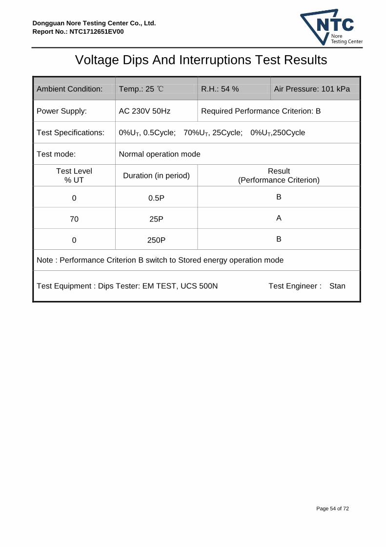
Voltage Dips And Interruptions Test Results
Ambient Condition: Temp.: 25 ℃ R.H.: 54 % Air Pressure: 101 kPa
Power Supply: AC 230V 50Hz Required Performance Criterion: B
Test Specifications: 0%UT, 0.5Cycle; 70%UT, 25Cycle; 0%UT,250Cycle
Test mode: Normal operation mode
Test Level % UT
Duration (in period) Result
(Performance Criterion)
0 0.5P B
70 25P A
0 250P B
Note : Performance Criterion B switch to Stored energy operation mode
Test Equipment : Dips Tester: EM TEST, UCS 500N Test Engineer : Stan

Dongguan Nore Testing Center Co., Ltd.
Report No.: NTC1712651EV00
Page 55 of 72
16.MAGNETIC FIELD IMMUNITY TEST
16.1 Block Diagram of Test Setup
16.2 Test Standard and Severity Levels
16.2.1 Test Standard EN 62040-2: 2006+AC: 2006 Category C2 (EN 61000-4-8: 2010, Severity Level 4: 30A/m)
16.2.2 Severity level
Performance Criterion : B
Level Magnetic Field Strength A/m
1. 1 2. 3
3. 10
4. 30
5. 100
X Special
I
/
O
C
a
b
l
e
A
C M
a
i
n
s
Magnetic Field Test
re Amplifier eld T
ster
EUT
Ground Reference Plane
Tower

Dongguan Nore Testing Center Co., Ltd.
Report No.: NTC1712651EV00
Page 56 of 72
16.3 Test Procedure
The E.U.T. is placed in the middle of a induction coil (1*1m), under which is a 1*1*0.8m (high)table, this small table is also placed on a larger table, 0.1 m above the ground. X, Y and Z polarization of the induction coil are set on test, so that each side of the E.U.T. is affected by the magnetic field. Also can reach the same aim by change the position of the E.U.T..
16.4 Test Result
PASS.
Please refer to the following page.

Dongguan Nore Testing Center Co., Ltd.
Report No.: NTC1712651EV00
Page 57 of 72
Magnetic Field Immunity Test Results
Ambient Condition: Temp.: 22 ℃ R.H.: 52 % Air Pressure: 101 kPa
Power Supply: AC 230V 50Hz, DC 48V
Required Performance Criterion: B
Test Specifications: 30A/m
Test mode: Normal operation mode, Stored energy operation mode
Test Level Testing Duration Coil Orientation Result
(Performance Criterion)
30A/m 5 mins X A
30A/m 5 mins Y A
30A/m 5 mins Z A
Note :
Test Equipment : Magnetic field test(HAEFELY, MAG100.1) Test Engineer : Sance

Dongguan Nore Testing Center Co., Ltd.
Report No.: NTC1712651EV00
Page 58 of 72
17.PHOTOGRAPH
17.1 Photo of Conducted Emission Measurement
17.2 Photo of Radiation Emission Measurement

Dongguan Nore Testing Center Co., Ltd.
Report No.: NTC1712651EV00
Page 59 of 72
17.3 Photo of Harmonic Measurement/ Flicker Measurement
17.4 Photo of Electrostatic Discharge Test

Dongguan Nore Testing Center Co., Ltd.
Report No.: NTC1712651EV00
Page 60 of 72
17.5 Photo of Electrical Fast Transient /Surge /Dips Test

Dongguan Nore Testing Center Co., Ltd.
Report No.: NTC1712651EV00
Page 61 of 72
APPENDIX I (Photos of E.U.T.)

Dongguan Nore Testing Center Co., Ltd.
Report No.: NTC1712651EV00
Page 62 of 72
Figure 1 General Appearance of the E.U.T. For APC trademark
Figure 2 General Appearance of the E.U.T.

Dongguan Nore Testing Center Co., Ltd.
Report No.: NTC1712651EV00
Page 63 of 72
Figure 3 General Appearance of the E.U.T.
For APC trademark
Figure 4 General Appearance of the E.U.T.
For Schneider trademark

Dongguan Nore Testing Center Co., Ltd.
Report No.: NTC1712651EV00
Page 64 of 72
Figure 5 General Appearance of the E.U.T.
Figure 6 General Appearance of the E.U.T.

Dongguan Nore Testing Center Co., Ltd.
Report No.: NTC1712651EV00
Page 65 of 72
Figure 7 General Appearance of the E.U.T.
Figure 8 General Appearance of the E.U.T.

Dongguan Nore Testing Center Co., Ltd.
Report No.: NTC1712651EV00
Page 66 of 72
Figure 9 General Appearance of the E.U.T.
Figure 10 General Appearance of the E.U.T.

Dongguan Nore Testing Center Co., Ltd.
Report No.: NTC1712651EV00
Page 67 of 72
Figure 11 General Internal of the E.U.T.
Figure 12 General Internal of the E.U.T.

Dongguan Nore Testing Center Co., Ltd.
Report No.: NTC1712651EV00
Page 68 of 72
Figure 13 General Appearance of the PCB
Figure14 General Appearance of the PCB

Dongguan Nore Testing Center Co., Ltd.
Report No.: NTC1712651EV00
Page 69 of 72
Figure 15 General Appearance of the PCB
Figure 16 General Appearance of the PCB

Dongguan Nore Testing Center Co., Ltd.
Report No.: NTC1712651EV00
Page 70 of 72
Figure 17 General Appearance of the PCB
Figure 18 General Appearance of the PCB

Dongguan Nore Testing Center Co., Ltd.
Report No.: NTC1712651EV00
Page 71 of 72
Figure 19 General Appearance of the PCB
Figure 20 General Appearance of the PCB

Dongguan Nore Testing Center Co., Ltd.
Report No.: NTC1712651EV00
Page 72 of 72
Figure 21 General Appearance of the PCB
Figure 22 General Appearance of the PCB
--- End of report ---


![Ppt0000000.ppt [Read-Only] › fusion › fusion... · Farqo Flood Forecast Chrgnology (Springt 2009) First Crest. 19 Mar 20 Mar 22 Mar 23 Mar 24 Mar 25 Mar 26 Mar 27 Mar 28 Mar [11:40am]](https://static.fdocuments.us/doc/165x107/5ed66ad521e1ec2b445e3dc9/read-only-a-fusion-a-fusion-farqo-flood-forecast-chrgnology-springt.jpg)
