EMC Test Reportcsi/products/manuals/TH-9800_EMC Report_PMR... · 2015. 1. 9. · EMC Test Report...
32
Report No.: AGC01039140302EE01 Page 1 of 32 EMC Test Report Report No.: AGC01039140302EE01 TEST NAME : 1999/5/EC R&TTE Directive Art.3.1(b) PRODUCT DESIGNATION : Mobile radio BRAND NAME : TYT MODEL NAME : TH‐9800, TH‐9800D, TH‐7800,TH‐7900 CLIENT : TYT ELECTRONICS CO., LTD DATE OF ISSUE : Apr. 18, 2014 STANDARD(S) : ETSI EN 301 489‐1 V1.9.2 (2011‐09) ETSI EN 301 489‐15 V1.2.1 (2002‐08) REPORT VERSION : V1.0 Attestation of Global Compliance (Shenzhen) Co., Ltd CAUTION: This report shall not be reproduced except in full without the written permission of the test laboratory and shall not be quoted out of context.
Transcript of EMC Test Reportcsi/products/manuals/TH-9800_EMC Report_PMR... · 2015. 1. 9. · EMC Test Report...
Report No.: AGC01039140302EE01 Page 1 of 32
EMC Test Report
Report No.: AGC01039140302EE01
TEST NAME : 1999/5/EC R&TTE Directive Art.3.1(b)
PRODUCT DESIGNATION
: Mobile radio
BRAND NAME : TYT
MODEL NAME : TH‐9800, TH‐9800D, TH‐7800,TH‐7900
CLIENT : TYT ELECTRONICS CO., LTD
DATE OF ISSUE : Apr. 18, 2014
STANDARD(S) : ETSI EN 301 489‐1 V1.9.2 (2011‐09) ETSI EN 301 489‐15 V1.2.1 (2002‐08)
REPORT VERSION : V1.0
Attestation of Global Compliance (Shenzhen) Co., Ltd
CAUTION: This report shall not be reproduced except in full without the written permission of the test laboratory and shall not be quoted out of context.

Report No.: AGC01039140302EE01 Page 2 of 32
REPORT REVISE RECORD
Report Version Revise Time Issued DateValid
Version Notes
V1.0 / Apr.18, 2014 Valid Original Report
Report No.: AGC01039140302EE01 Page 3 of 32
TABLE OF CONTENTS 1. GENERAL INFORMATION ....................................................................................................................... 4 2. EUT DESCRIPTION .................................................................................................................................. 5 3. TEST METHODOLOGY ............................................................................................................................ 6
3.1 UNIT OF MEASUREMENT .................................................................................................................. 6
3.2 ANTENNA ............................................................................................................................................ 6
3.3 DECISION OF TEST MODE ................................................................................................................ 7
4. INSTRUMENT AND CALIBRATION ......................................................................................................... 8 4.1 MEASURING INSTRUMENT CALIBRATION ...................................................................................... 8
5. FACILITIES AND ACCREDITATIONS ...................................................................................................... 9 5.1 FACILITIES .......................................................................................................................................... 9
5.2 EQUIPMENT ....................................................................................................................................... 9
6. SETUP OF EQUIPMENT UNDER TEST ................................................................................................ 10 6.1 SETUP CONFIGURATION OF EUT .................................................................................................. 10
6.2 SUPPORT EQUIPMENT ................................................................................................................... 10
6.3 TEST SETUP ..................................................................................................................................... 10
7. ETSI EN 301 489-1/-15 REQUIREMENTS .............................................................................................. 11 7.1 CONDUCTED TRANSIENT EMISSION MEASUREMENT ................................................................. 11
7.2 RADIATED EMISSION ...................................................................................................................... 14
7.3 RF ELECTROMAGNETIC FIELD ...................................................................................................... 17
7.4 TRANSIENTS AND SURGES IN THE VEHICULAR ENVIRONMENT .............................................. 19
7.5 DC MAINS RF – COMMON MODE ................................................................................................... 21
APPENDIX 1 ............................................................................................................................................... 23 PHOTOGRAPHS OF TEST SETUP ........................................................................................................... 23 APPENDIX 2 ............................................................................................................................................... 25 PHOTOGRPHS OF EUT ............................................................................................................................. 25
Report No.: AGC01039140302EE01 Page 4 of 32
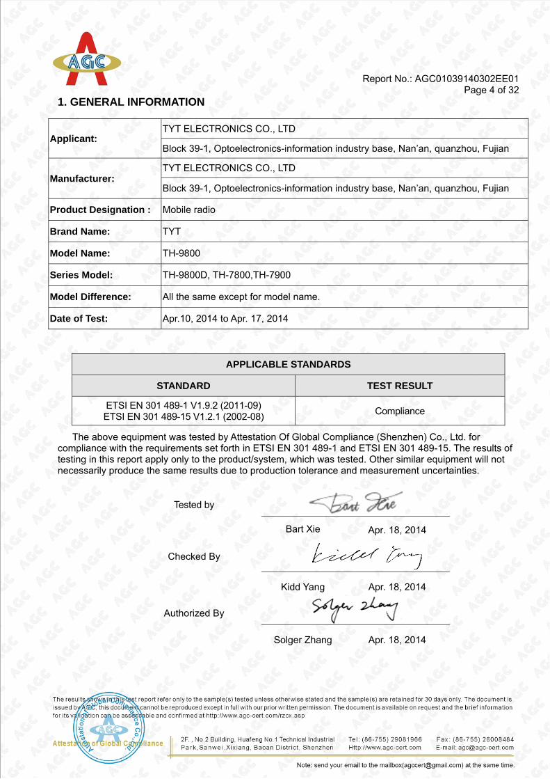
1. GENERAL INFORMATION
APPLICABLE STANDARDS
STANDARD TEST RESULT
ETSI EN 301 489-1 V1.9.2 (2011-09) ETSI EN 301 489-15 V1.2.1 (2002-08) Compliance
The above equipment was tested by Attestation Of Global Compliance (Shenzhen) Co., Ltd. for compliance with the requirements set forth in ETSI EN 301 489-1 and ETSI EN 301 489-15. The results of testing in this report apply only to the product/system, which was tested. Other similar equipment will not necessarily produce the same results due to production tolerance and measurement uncertainties.
Applicant: TYT ELECTRONICS CO., LTD
Block 39-1, Optoelectronics-information industry base, Nan’an, quanzhou, Fujian
Manufacturer: TYT ELECTRONICS CO., LTD
Block 39-1, Optoelectronics-information industry base, Nan’an, quanzhou, Fujian
Product Designation : Mobile radio
Brand Name: TYT
Model Name: TH-9800
Series Model: TH-9800D, TH-7800,TH-7900
Model Difference: All the same except for model name.
Date of Test: Apr.10, 2014 to Apr. 17, 2014
Tested by
Bart Xie Apr. 18, 2014
Checked By
Kidd Yang Apr. 18, 2014
Authorized By
Solger Zhang Apr. 18, 2014
Report No.: AGC01039140302EE01 Page 5 of 32
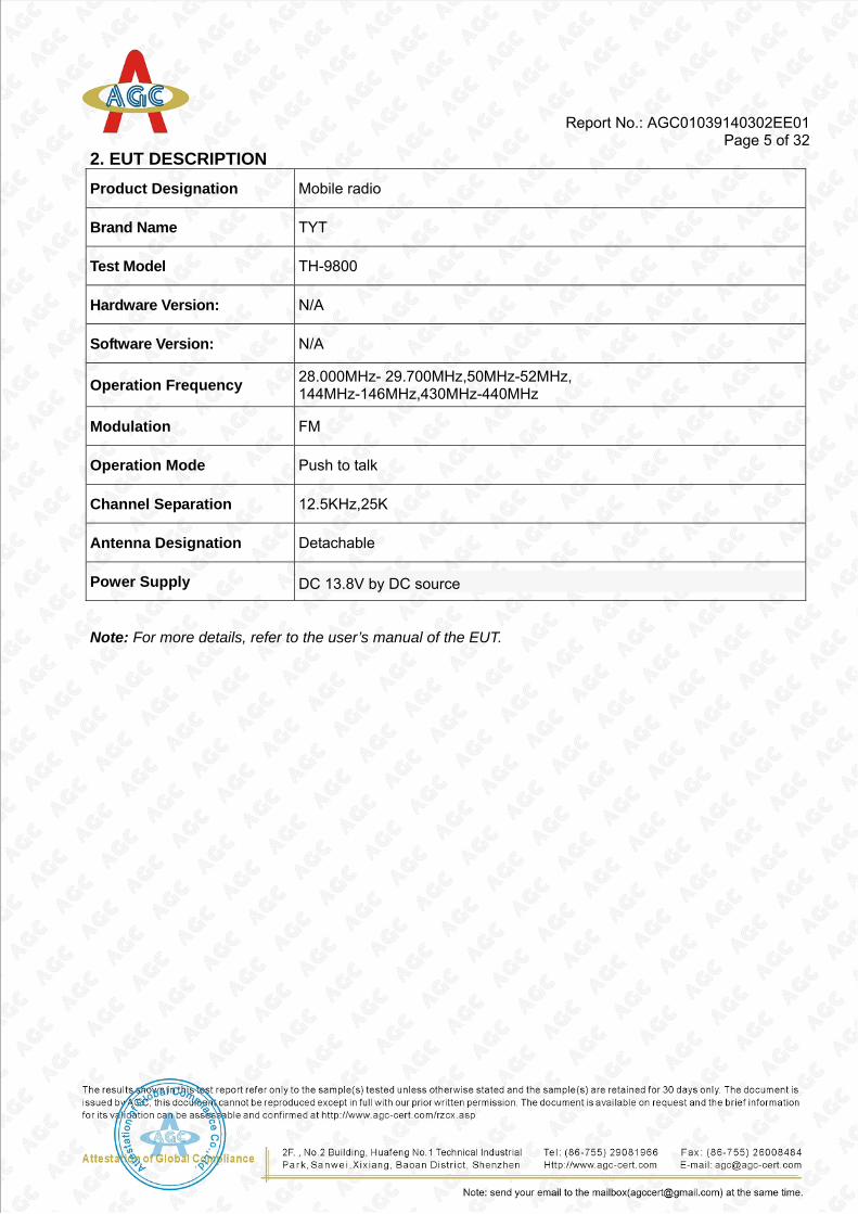
2. EUT DESCRIPTION Product Designation Mobile radio
Brand Name TYT
Test Model TH-9800
Hardware Version: N/A
Software Version: N/A
Operation Frequency 28.000MHz- 29.700MHz,50MHz-52MHz, 144MHz-146MHz,430MHz-440MHz
Modulation FM
Operation Mode Push to talk
Channel Separation 12.5KHz,25K
Antenna Designation Detachable
Power Supply DC 13.8V by DC source
Note: For more details, refer to the user’s manual of the EUT.

Report No.: AGC01039140302EE01 Page 6 of 32
3. TEST METHODOLOGY All tests were performed in accordance with the procedure documented in ETSI EN 301 489-1 V1.9.2 (2011-09) as referenced in ETSI EN 301 489-15 V1.2.1 (2002-08).
3.1 UNIT OF MEASUREMENT Measurements of radiated interference are reported in terms of dB(uV/m) at a specified distance. The indicated readings on the Spectrum analyzers were converted to dB (uV/m) by use of appropriate conversion factors. Measurements of conducted interference are reported in terms of dB(uV).
The field strength is calculated by adding the Antenna Factor and Cable Factors and subtracting the Amplifier Gain from the measured reading. The following is a sample calculation:
FS = RA + AF + CF - AG
Where FS = Field Strength RA = Receiver Amplitude AF = Antenna Factor CF = Cable Attenuation Factor AG = Amplifier Gain
Assume a receiver reading of 52.5 dBuV is obtained. The Antenna Factor of 7.4dB/m and a Cable Factor of 1.1dB are added. The Amplifier Gain of 29 dB is subtracted, giving field strength of 32 dBuV/m. The 32-dBuV/m values was mathematically converted to its corresponding level in uV/m.
FS = 52.5 + 7.4 + 1.1 - 29 = 32 dBuV/m Note: Level in uV/m = Common Antilogarithm [(32 dBuV/m)/20] = 39.8 uV/m
3.2 ANTENNA The calibrated antennas used to sample the radiated field strength are mounted on a non-conductive, motorized antenna mast 3 meters from the leading edge of the turntable.
Perform Electro Magnetic Susceptibility (EMS) tests.
Report No.: AGC01039140302EE01 Page 7 of 32
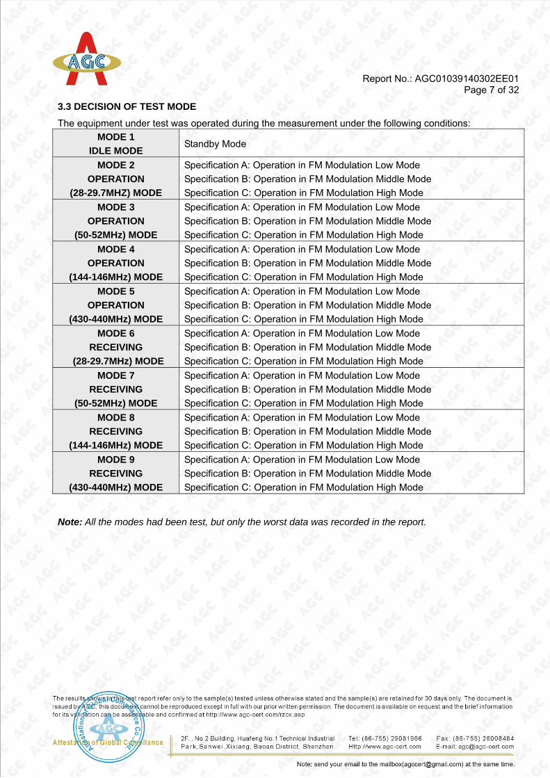
3.3 DECISION OF TEST MODE The equipment under test was operated during the measurement under the following conditions:
MODE 1 IDLE MODE
Standby Mode
MODE 2 OPERATION
(28-29.7MHZ) MODE
Specification A: Operation in FM Modulation Low Mode Specification B: Operation in FM Modulation Middle Mode Specification C: Operation in FM Modulation High Mode
MODE 3 OPERATION
(50-52MHz) MODE
Specification A: Operation in FM Modulation Low Mode Specification B: Operation in FM Modulation Middle Mode Specification C: Operation in FM Modulation High Mode
MODE 4 OPERATION
(144-146MHz) MODE
Specification A: Operation in FM Modulation Low Mode Specification B: Operation in FM Modulation Middle Mode Specification C: Operation in FM Modulation High Mode
MODE 5 OPERATION
(430-440MHz) MODE
Specification A: Operation in FM Modulation Low Mode Specification B: Operation in FM Modulation Middle Mode Specification C: Operation in FM Modulation High Mode
MODE 6 RECEIVING
(28-29.7MHz) MODE
Specification A: Operation in FM Modulation Low Mode Specification B: Operation in FM Modulation Middle Mode Specification C: Operation in FM Modulation High Mode
MODE 7 RECEIVING
(50-52MHz) MODE
Specification A: Operation in FM Modulation Low Mode Specification B: Operation in FM Modulation Middle Mode Specification C: Operation in FM Modulation High Mode
MODE 8 RECEIVING
(144-146MHz) MODE
Specification A: Operation in FM Modulation Low Mode Specification B: Operation in FM Modulation Middle Mode Specification C: Operation in FM Modulation High Mode
MODE 9 RECEIVING
(430-440MHz) MODE
Specification A: Operation in FM Modulation Low Mode Specification B: Operation in FM Modulation Middle Mode Specification C: Operation in FM Modulation High Mode
Note: All the modes had been test, but only the worst data was recorded in the report.
Report No.: AGC01039140302EE01 Page 8 of 32
4. INSTRUMENT AND CALIBRATION 4.1 MEASURING INSTRUMENT CALIBRATION The measuring equipment, which was utilized in performing the tests documented herein, has been calibrated in accordance with the manufacturer's recommendations for utilizing calibration equipment, which is traceable to recognized national standards.
The uncertainty is calculated using the methods suggested in the “Guide to the Expression of Uncertainty
in Measurement” (GUM) published by ISO. - Uncertainty of Conducted Emission, Uc = ±2.75dB - Uncertainty of Radiated Emission, Uc = ±3.2dB

Report No.: AGC01039140302EE01 Page 9 of 32
5. FACILITIES AND ACCREDITATIONS 5.1 FACILITIES The test site used to collect the radiated data is located on the address of Attestation of Global Compliance (Shenzhen) Co., Ltd. 2/F., Building 2, No.1-No.4, Chaxi Sanwei Technical Industrial Park, Gushu, Xixiang, Bao'an District, Shenzhen, Guangdong, China The test site is constructed and calibrated to meet the FCC requirements in documents ANSI C63.4: 2003.
FCC register No.: 259865
5.2 EQUIPMENT Radiated emissions are measured with one or more of the following types of linearly polarized antennas: tuned dipole, biconical, log periodic, bi-log, and/or ridged waveguide, horn. Spectrum analyzers with preselectors and quasi-peak detectors are used to perform radiated measurements.
Conducted emissions are measured with Line Impedance Stabilization Networks and EMI Test Receivers.
Calibrated wideband preamplifiers, coaxial cables, and coaxial attenuators are also used for making measurements.
All receiving equipment conforms to CISPR Publication 16-1, “Radio Interference Measuring Apparatus and Measurement Methods.”
Report No.: AGC01039140302EE01 Page 10 of 32
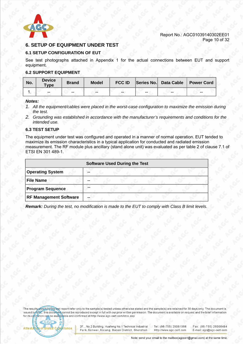
6. SETUP OF EQUIPMENT UNDER TEST 6.1 SETUP CONFIGURATION OF EUT See test photographs attached in Appendix 1 for the actual connections between EUT and support equipment.
6.2 SUPPORT EQUIPMENT
No. Device Type Brand Model FCC ID Series No. Data Cable Power Cord
1. -- -- -- -- -- -- --
Notes: 1. All the equipment/cables were placed in the worst-case configuration to maximize the emission during
the test. 2. Grounding was established in accordance with the manufacturer’s requirements and conditions for the
intended use.
6.3 TEST SETUP The equipment under test was configured and operated in a manner of normal operation. EUT tended to maximize its emission characteristics in a typical application for conducted and radiated emission measurement. The RF module plus ancillary (stand alone unit) was evaluated as per table 2 of clause 7.1 of ETSI EN 301 489-1.
Software Used During the Test
Operating System --
File Name --
Program Sequence --
RF Management Software --
Remark: During the test, no modification is made to the EUT to comply with Class B limit levels.

Report No.: AGC01039140302EE01 Page 11 of 32
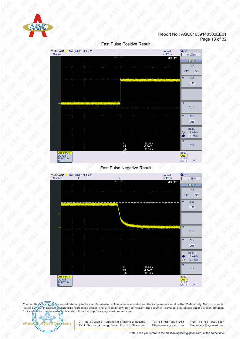
7. ETSI EN 301 489-1/-15 REQUIREMENTS 7.1 CONDUCTED TRANSIENT EMISSION MEASUREMENT
LIMIT
Pulse Amplitude(US) Limit for US severity Level Ua
Positive +75 13.8V
Negative -100 13.8V
MEASUREMENT EQUIPMENT USED
Conducted Emission Test Site # 3
Name of Equipment Manufacturer Model Serial Number Calibration Due
Oscilloscope Tektronix DP04104 N/A 2014-07-17
LISN RS ESH3-Z6 N/A 2014-07-17
Remark: Each piece of equipment is scheduled for calibration once a year.
TEST PROCEDURE Please Refer to ISO7637-2
TEST RESULTS (OPERATION MODE)
The test modes were carried out for all operation modes The worst test data (test mode) was showed as the follow:

Report No.: AGC01039140302EE01 Page 12 of 32
Slow Pulse Positive Result
Slow Pulse Negative Result
Report No.: AGC01039140302EE01 Page 13 of 32
Fast Pulse Positive Result
Fast Pulse Negative Result

Report No.: AGC01039140302EE01 Page 14 of 32
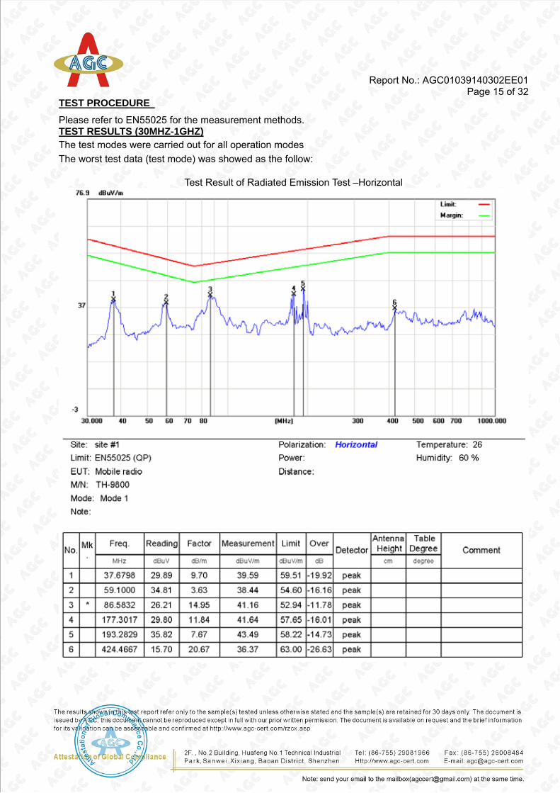
7.2 RADIATED EMISSION
LIMIT Please refer to EN55025 Standard.
MEASUREMENT EQUIPMENT USED
Radiated Emission Test Site # 4
Name of Equipment Manufacturer Model Serial Number Calibration Due
EMI TEST RECEIVER RS ESCI 100307 2014-07-17
AMPLIFIER HP HP8447D 2944A10419 2014-07-17
ANTENNA A.H. SAS-521-4 9163-194 2014-07-17
LISN R&S ESH3-Z6 N/A 2014-07-17
Remark: Each piece of equipment is scheduled for calibration once a year.
TEST CONFIGURATION
F ilter F ilter F ilter To Power
E UT
G round P lane 3m
0.8 m
Coax ia l C ab le
T urn tab le 1m ~ 4m
PowerCable
E M I Rece iver
F ilte r
1m
Filter
Report No.: AGC01039140302EE01 Page 15 of 32
TEST PROCEDURE Please refer to EN55025 for the measurement methods. TEST RESULTS (30MHZ-1GHZ) The test modes were carried out for all operation modes The worst test data (test mode) was showed as the follow:
Test Result of Radiated Emission Test –Horizontal

Report No.: AGC01039140302EE01 Page 16 of 32
Test Result of Radiated Emission Test –Vertical
Report No.: AGC01039140302EE01 Page 17 of 32
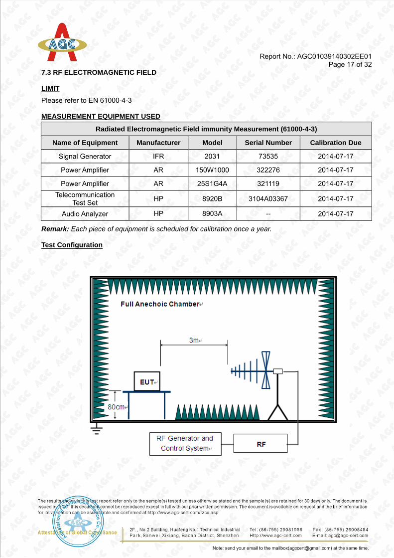
7.3 RF ELECTROMAGNETIC FIELD
LIMIT Please refer to EN 61000-4-3
MEASUREMENT EQUIPMENT USED
Radiated Electromagnetic Field immunity Measurement (61000-4-3)
Name of Equipment Manufacturer Model Serial Number Calibration Due
Signal Generator IFR 2031 73535 2014-07-17
Power Amplifier AR 150W1000 322276 2014-07-17
Power Amplifier AR 25S1G4A 321119 2014-07-17 Telecommunication
Test Set HP 8920B 3104A03367 2014-07-17
Audio Analyzer HP 8903A -- 2014-07-17
Remark: Each piece of equipment is scheduled for calibration once a year.
Test Configuration

Report No.: AGC01039140302EE01 Page 18 of 32
Ambient Condition of the Test Site
Temperature 22°C EUT AC Voltage Rating N/A
Humidity 50%RH EUT DC Voltage Rating DC13.8V
Pressure 990 mbar Ground Bond Resistance 0.2 Ω
Tested by Wall
TEST PROCEDURE Please refer to ETSI EN 301 489-1 Clause 9.2.2, ETSI EN 301 489-5 Clause 7.2.2 and EN 61000-4-3 for the measurement methods.
TEST RESULTS During the assessment of CT and CR, the audio quality was monitored by a distortion analyzer located outside the test environment. An audio generator has been used to provide necessary modulation for CT test and for CR evaluation, an RF Generator has been used to provide source.
EUT Working
Mode
Antenna Polarity
Frequency (MHz)
Field Strength
(V/m)
Audio Distortion Observation Conclusion
Operating Mode
H/V 1400-2700 3 7.5% CT Pass
H/V 80-1000 3 10.4% CT Pass
Receiving Mode
H/V 1400-2700 3 8.8% CR Pass
H/V 80-1000 3 13.3% CR Pass
Note: There was not any unintentional transmission discovered in standby mode
Report No.: AGC01039140302EE01 Page 19 of 32
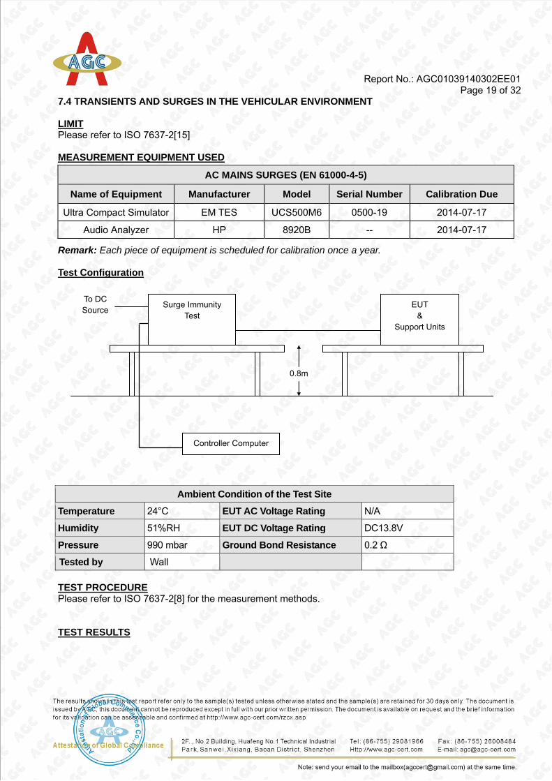
7.4 TRANSIENTS AND SURGES IN THE VEHICULAR ENVIRONMENT
LIMIT Please refer to ISO 7637-2[15]
MEASUREMENT EQUIPMENT USED
AC MAINS SURGES (EN 61000-4-5)
Name of Equipment Manufacturer Model Serial Number Calibration Due
Ultra Compact Simulator EM TES UCS500M6 0500-19 2014-07-17
Audio Analyzer HP 8920B -- 2014-07-17
Remark: Each piece of equipment is scheduled for calibration once a year.
Test Configuration
Ambient Condition of the Test Site
Temperature 24°C EUT AC Voltage Rating N/A
Humidity 51%RH EUT DC Voltage Rating DC13.8V
Pressure 990 mbar Ground Bond Resistance 0.2 Ω
Tested by Wall
TEST PROCEDURE Please refer to ISO 7637-2[8] for the measurement methods.
TEST RESULTS
Surge Immunity Test
Controller Computer
EUT &
Support Units
0.8m
To DC Source
Report No.: AGC01039140302EE01 Page 20 of 32
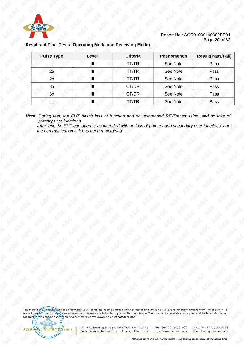
Results of Final Tests (Operating Mode and Receiving Mode)
Pulse Type Level Criteria Phenomenon Result(Pass/Fail)
1 III TT/TR See Note Pass
2a III TT/TR See Note Pass
2b III TT/TR See Note Pass
3a III CT/CR See Note Pass
3b III CT/CR See Note Pass
4 III TT/TR See Note Pass
Note: During test, the EUT hasn’t loss of function and no unintended RF-Transmission, and no loss of primary user functions.
After test, the EUT can operate as intended with no loss of primary and secondary user functions, and the communication link has been maintained.

Report No.: AGC01039140302EE01 Page 21 of 32
CDN
EUT and Support units Power
Amplifier PC Controller
Ground Reference Plane
10 cm isolation supporter
0.1m< L <0.3m
7.5 DC MAINS RF – COMMON MODE
LIMIT Please refer to EN 61000-4-6
MEASUREMENT EQUIPMENT USED
AC MAINS RF COMMON MODE (EN 61000-4-6)
Name of Equipment Manufacturer Model Serial Number Calibration Due
Signal Generator AGILENT E4412B -- 2014-07-17
Amplifier AR 75A250A 302276 2014-07-17
Dual Directional Coupler AR DC2600A 302389 2014-07-17
CDN EM TEST CDN M1/32A 0201-01 2014-07-17
Audio Analyzer HP 8920B -- 2014-07-17
Remark: Each piece of equipment is scheduled for calibration once a year.
Test Configuration
Ambient Condition of the Test Site
Temperature 25°C EUT AC Voltage Rating N/A
Humidity 52%RH EUT DC Voltage Rating DC13.8V
Pressure 990 mbar Ground Bond Resistance 0.2 Ω
Tested by Wall
TEST PROCEDURE Please refer to ETSI EN 301 489-1 Clause 9.5.2 and EN 61000-4-6 for the measurement methods.

Report No.: AGC01039140302EE01 Page 22 of 32
TEST RESULTS
Results of Final Tests (Operating Mode and Receiving Mode)
Frequency Range: 0.15MHz~80MHz Frequency Step: 1% of fundamental Dwell time: 3 Sec.
80% A.M., 1K Hz Sine wave (Voltage: 3 V)
Coupling type: CDN / RF Current Probe
EUT Working Mode
Test Point Frequency
(MHz)
Field Strength (Vrms)
Audio Distortion
Observation Conclusion
Operating Mode a.c. port 0.15 – 80 3 6.6% CT Pass
Receiving Mode a.c. port 0.15 – 80 3 13.1% CR Pass
Note: There was not any unintentional transmission in Standby mode

Report No.: AGC01039140302EE01 Page 23 of 32
APPENDIX 1 PHOTOGRAPHS OF TEST SETUP CONDUCTED EMISSION TEST SETUP
RADIATED TEST SETUP

Report No.: AGC01039140302EE01 Page 24 of 32
RADIATED TEST SETUP
Report No.: AGC01039140302EE01 Page 25 of 32
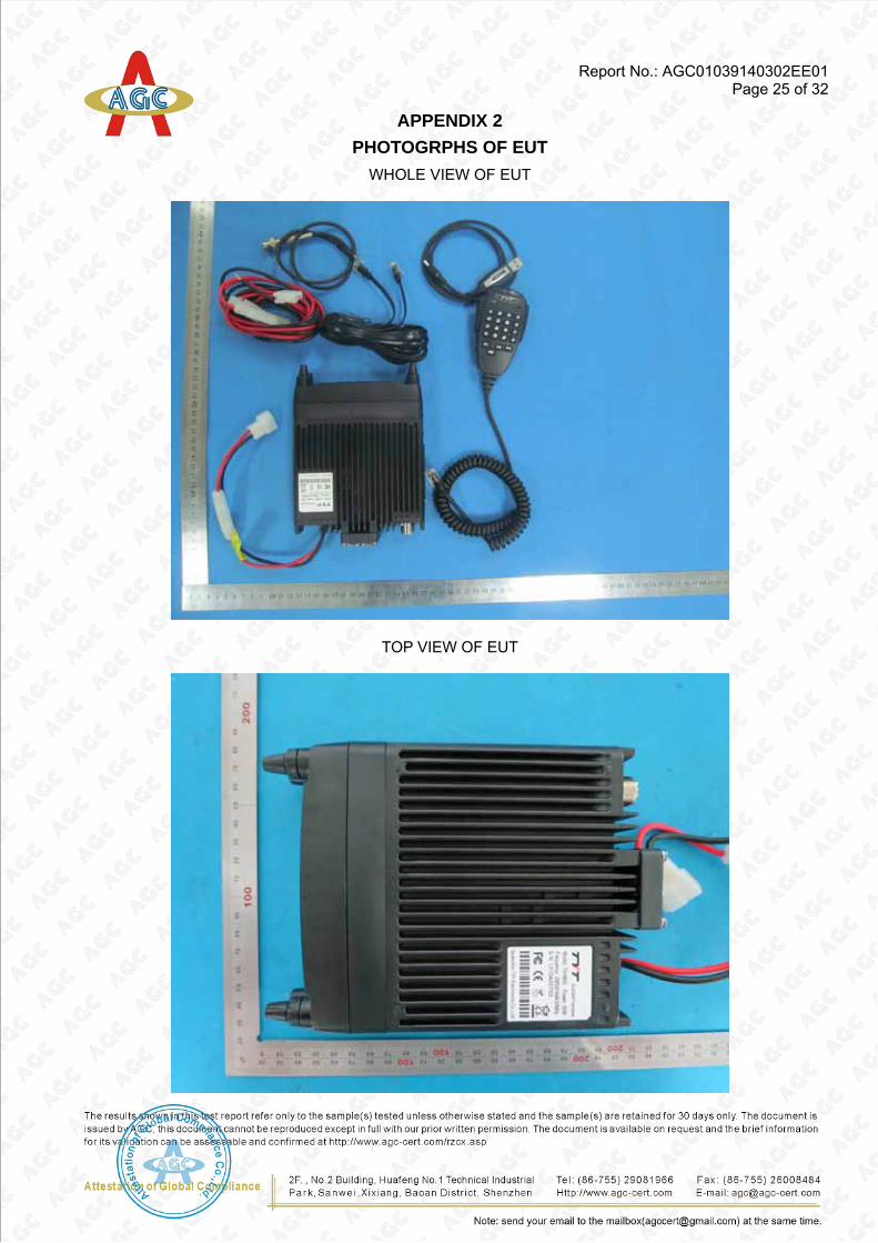
APPENDIX 2 PHOTOGRPHS OF EUT
WHOLE VIEW OF EUT
TOP VIEW OF EUT

Report No.: AGC01039140302EE01 Page 26 of 32
BOTTOM VIEW OF EUT
FRONT VIEW OF EUT

Report No.: AGC01039140302EE01 Page 27 of 32
BACK VIEW OF EUT
LEFT VIEW OF EUT

Report No.: AGC01039140302EE01 Page 28 of 32
RIGHT VIEW OF EUT
OPEN VIEW OF EUT
Report No.: AGC01039140302EE01 Page 29 of 32
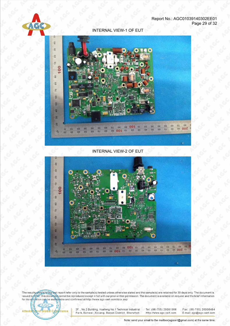
INTERNAL VIEW-1 OF EUT
INTERNAL VIEW-2 OF EUT

Report No.: AGC01039140302EE01 Page 30 of 32
INTERNAL VIEW-3 OF EUT
INTERNAL VIEW-4 OF EUT

Report No.: AGC01039140302EE01 Page 31 of 32
INTERNAL VIEW-5 OF EUT
INTERNAL VIEW-6 OF EUT
Report No.: AGC01039140302EE01 Page 32 of 32
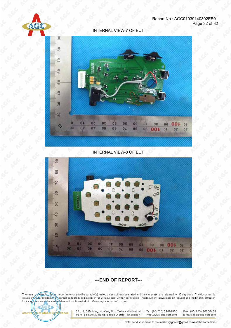
INTERNAL VIEW-7 OF EUT
INTERNAL VIEW-8 OF EUT
---END OF REPORT---