
Embedded Systems VI · Design And Development Of A Micro Mouse Wall Follower Assignment Steven P....
67
Embedded Systems VI Design And Development Of A Micro- Mouse Wall Follower Assignment Prepared by: Steven P. Smith Student ID: 01702327 Subject: Embedded Systems VI Course: BSc (Hons) Computing and Electronics Part Time Date: 20 th May 2003 File: \\Embed6\Assign2\Assign2.doc
Transcript of Embedded Systems VI · Design And Development Of A Micro Mouse Wall Follower Assignment Steven P....

Embedded Systems VI
Design And Development Of A Micro- Mouse Wall Follower
Assignment Prepared by: Steven P. Smith Student ID: 01702327 Subject: Embedded Systems VI Course: BSc (Hons) Computing and Electronics � Part Time Date: 20th May 2003 File: \�\Embed6\Assign2\Assign2.doc
Design And Development Of A Micro Mouse Wall Follower Assignment
Steven P. Smith
Student ID: 01702327
Embedded Systems VI Page 2 of 67
BSc (Hons) Computing & Electronics PT
Contents Preface ................................................................................................................................5
1 AIM OF REPORT..............................................................................................................6
2 INTRODUCTION................................................................................................................6
2.1 THE CHALLENGE......................................................................................................6 2.2 SYSTEM OVERVIEW..................................................................................................6
3 THE DEVELOPMENT PROCESS..........................................................................................7
3.1 SYSTEM OVERVIEW..................................................................................................7 3.2 TRACKING AND TURNING PRINCIPLES........................................................................8 3.3 HARDWARE DESIGN SPECIFICATION ........................................................................10 3.4 HARDWARE ALLOCATION ........................................................................................12 3.5 SOFTWARE DEVELOPMENT .....................................................................................12
4 DRIVE SYSTEM .............................................................................................................14
4.1 THE MOTOR ..........................................................................................................14 4.2 GEARING...............................................................................................................14 4.3 MOTOR/WHEEL ASSEMBLY .....................................................................................15 4.4 MOTOR CONTROL BOARD.......................................................................................15
5 POWER SOURCE...........................................................................................................17
5.1 SELECTION............................................................................................................17 5.2 BATTERY VOLTAGE AND CAPACITY ..........................................................................17 5.3 SURGE CURRENT CAPABILITY .................................................................................17 5.4 CIRCUIT CURRENT REQUIREMENTS .........................................................................18 5.5 MEMORY EFFECT...................................................................................................18
6 CONTROLLER - HARDWARE............................................................................................19
6.1 MICROCONTROLLER ...............................................................................................19 6.2 SENSORS ..............................................................................................................21 6.3 INTERFACES ..........................................................................................................23 6.4 ADDITIONAL CIRCUITRY ..........................................................................................24 6.5 PCB DESIGN � FIRST ATTEMPT ..............................................................................27 6.6 PCB DESIGN � FINAL DESIGN.................................................................................28
7 PCB BUILD PHASE........................................................................................................28
7.1 PROCESS STEPS ...................................................................................................28 7.2 PRINTING THE LAYOUT ...........................................................................................28

Design And Development Of A Micro Mouse Wall Follower Assignment
Steven P. Smith
Student ID: 01702327
Embedded Systems VI Page 3 of 67
BSc (Hons) Computing & Electronics PT
8 TEST SEQUENCE ...........................................................................................................28
8.1 OPEN CIRCUIT TEST ...............................................................................................28 8.2 SHORT CIRCUIT TEST .............................................................................................28 8.3 RECTIFICATIONS ....................................................................................................28 8.4 FUTURE AMENDMENTS ...........................................................................................28 8.5 INITIAL BOARD TEST CONDITION..............................................................................28 8.6 TEST DEFINITIONS/RESULTS...................................................................................28 8.7 CIRCUIT AMENDMENTS ...........................................................................................28 8.8 TEST ZONES..........................................................................................................28 8.9 BOARD COMPONENT ALLOCATIONS .........................................................................28 8.10 TEST ALGORITHM...................................................................................................28
9 FINAL ASSEMBLY...........................................................................................................28
10 CONTROLLER - SOFTWARE.........................................................................................28
10.1 INITIAL SOFTWARE STRUCTURE...............................................................................28 10.2 CALCULATING THE PWM ........................................................................................28 10.3 DEVELOPING THE CODE .........................................................................................28 10.4 THE CODE.............................................................................................................28
11 COMMISSIONING........................................................................................................28
12 CONCLUSION (OBSERVATIONS/LESSONS LEARNT) .......................................................28
APPENDIX A - Original Specification Document ...............................................................28
APPENDIX B � Example Nickel-Cadmium Rechargeable Battery Data Sheet..................28
APPENDIX C � Example Nickel-Metal Hydride Rechargeable Battery Data Sheet...........28
APPENDIX D � Example Alkaline Non-Rechargeable Battery Data Sheet........................28
APPENDIX E � Glossary Of Battery Terms.......................................................................28

Design And Development Of A Micro Mouse Wall Follower Assignment
Steven P. Smith
Student ID: 01702327
Embedded Systems VI Page 4 of 67
BSc (Hons) Computing & Electronics PT
Reference information: http://www.microchip.com Micro-controller 16F877 datasheet
http://web.tic.ac.uk/staff/wilcoxt/ Module and Micro-mouse Support Documentation
http://web.tic.ac.uk/staff/wilcoxt/ Robotic Support Documentation Version 1.5
Embedded Systems VI Autonomous Guided Vehicle (AGV) Object Detection Sensors Assignment
http://www.energizer.com Battery Information

Design And Development Of A Micro Mouse Wall Follower Assignment
Steven P. Smith
Student ID: 01702327
Embedded Systems VI Page 5 of 67
BSc (Hons) Computing & Electronics PT
Preface This report contains the conceptual and design material used to produce a working Micro-Mouse, which was demonstrated to Dr. Anthony Wilcox on the 20.05.03, showing a successful conclusion to the build phase of the assignment. The Micro-Mouse project was the joint effort of a team of three members as agreed with Dr. Wilcox.
(The Team, from left to Right: Mark Pitt, Steve Smith and Giovanni Garzelli)
We held regular team meetings at Land Rover, Solihull on Friday afternoons. This provided an excellent forum to discuss concepts/proposals, as well as outstanding issues to be discussed and resolved during each design stage. Data captured during these discussions can be found within the report. An attached CD-ROM in support of this report will demonstrate the final Micro-Mouse design completing the specified maze construct. There are four video files on the CD-ROM showing an aerial view of the micro-robot completing a number of maze cycles, two "micro-robot level" turning sequence, and an on board view of the micro-robot as it navigates itself around the maze. We have tried to utilise the design techniques studied during previous Embedded and Software to aid the development and implement process.

Design And Development Of A Micro Mouse Wall Follower Assignment
Steven P. Smith
Student ID: 01702327
Embedded Systems VI Page 6 of 67
BSc (Hons) Computing & Electronics PT
1 Aim Of Report To record and review the design and development of a micro mouse that is capable of following a left hand wall. 2 Introduction 2.1 The Challenge The course that the wall-follower must negotiate is to be 4 squares by 4-squares of the existing micro mouse maze, with a total of 3 circuits of the so-formed rectangle. The groups will be given 3 runs, with the time of the best run being used to determine a winner. 2.2 System Overview The base elements required are a drive unit, power source, sensors, and a controller to bind them all together.
Controller
1
Drive Sensors
Power
Note: This should not normally be shown on thisdiagram. However, for the fullness of representingthe complete package, it has been included.
Command Signals Feedback Data
Power PowerPower

Design And Development Of A Micro Mouse Wall Follower Assignment
Steven P. Smith
Student ID: 01702327
Embedded Systems VI Page 7 of 67
BSc (Hons) Computing & Electronics PT
3 The Development Process The following notes capture how we arrived at our design through our regular meetings to discuss potential solutions, as well as resolve any outstanding issues. Since the drive unit and power unit was supplied by the TIC, the project was divided into three main topics:
1. controller and sensor design 2. software 3. build and test.
Each member of the team was designated as team leader for one of the topics, co-ordinating the activities of the team for that topic. This created a matrix approach, with each of us participating in all of the topics, but taking full responsibility for the delivery of one of them. 3.1 System Overview The first activity was to generate an overview of the system and its components. The diagram below shows how we first viewed its construct.
At first we assumed that we would be using all of the TIC�s peripheral devices, with only the micro-controller board requiring to be developed. The SPI data is the link required to interface with the TIC�s sensor board. The diagnostics were envisaged as additional LED�s, to providing a low level of debugging.
Design And Development Of A Micro Mouse Wall Follower Assignment
Steven P. Smith
Student ID: 01702327
Embedded Systems VI Page 8 of 67
BSc (Hons) Computing & Electronics PT
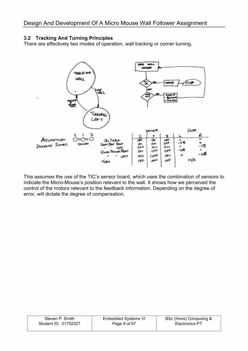
3.2 Tracking And Turning Principles There are effectively two modes of operation, wall tracking or corner turning.
This assumes the use of the TIC�s sensor board, which uses the combination of sensors to indicate the Micro-Mouse�s position relevant to the wall. It shows how we perceived the control of the motors relevant to the feedback information. Depending on the degree of error, will dictate the degree of compensation.

Design And Development Of A Micro Mouse Wall Follower Assignment
Steven P. Smith
Student ID: 01702327
Embedded Systems VI Page 9 of 67
BSc (Hons) Computing & Electronics PT
Next, we discussed the mechanics of negotiating a corner.
There are two methods we originally discussed, which are to drive the inner wheel at a slower than the outer wheel to cause the unit to arc around the corner. Alternatively, to drive forward a preset distances, then turn by driving the right wheel forward and the left wheel in reverse, both for an equal distance.

Design And Development Of A Micro Mouse Wall Follower Assignment
Steven P. Smith
Student ID: 01702327
Embedded Systems VI Page 10 of 67
BSc (Hons) Computing & Electronics PT
3.3 Hardware Design Specification The team reviewed the various proposals along with the learning from the first assignment concerning different sensors types. The outcome was as follows. Firstly, it was decided that we should develop our own sensors arrangement. This would comprise of 3 sensors, front, middle and rear. Each sensor comprises of an infrared LED and an infrared diode. The feedback from the sensors is to be monitored via the micro-controllers analogue ports, which can then be broken down into several bands. Each band represents a compensation factor that is used to adjust the motor output depending on were the wall is sensed.
Feedback
System Manager
Rear Sensor
Right Hand Drive Unit
Feedback
Left Hand Drive Unit
Front SensorMiddle Sensor
Infra Red Emitter
Photo Diode Band 1 Band 2 Band 3 Band 4 Band 5
Wall

Design And Development Of A Micro Mouse Wall Follower Assignment
Steven P. Smith
Student ID: 01702327
Embedded Systems VI Page 11 of 67
BSc (Hons) Computing & Electronics PT
The method of turning was a variation of the methods discussed earlier. The principle is to track until the front sensor can no longer find the wall, and then continue to travel forward in slow until the middle sensor also cannot detect the wall. The unit then executes a left turn by driving the right wheel only.
If all three sensors loose contact with the wall, excluding when turning, then the unit should stop.

Design And Development Of A Micro Mouse Wall Follower Assignment
Steven P. Smith
Student ID: 01702327
Embedded Systems VI Page 12 of 67
BSc (Hons) Computing & Electronics PT
3.4 Hardware Allocation Once the concept was formalised then the detail could begin. Since the Micro-Controller is a self-contained unit, this took the simple form of allocating the different function to the various pins of the 16F877 which was the chip allocated for this project.
3.5 Software Development Firstly, a broad based description of the required functionality, attempting to visualise the links and the triggers necessary between the different modules.

Design And Development Of A Micro Mouse Wall Follower Assignment
Steven P. Smith
Student ID: 01702327
Embedded Systems VI Page 13 of 67
BSc (Hons) Computing & Electronics PT
Next we began to structure the programme by breaking it down into functions, and the anticipated data required being available to the different functions. The aim was to partition the code into define sections to permit the team to share the code writing.
Finally, a review of the main( ) function, which effectively brings together all the other functions, acting as the �Manager�.

Design And Development Of A Micro Mouse Wall Follower Assignment
Steven P. Smith
Student ID: 01702327
Embedded Systems VI Page 14 of 67
BSc (Hons) Computing & Electronics PT
4 Drive System There are two main options available to us for driving the micro-mouse, which are DC motors or stepper motors. Stepper motors can be accurately controlled, but require more control software and/or support circuitry than a DC motors that tend to offer a readily available cheap option. The quality that a motor is manufactured to will affect its performance, i.e. torque, stability and efficiency. However, for this application a standard DC motor is more than adequate. TIC has a motor assembly with all the necessary mechanics and control circuitry, which the team decided to use. 4.1 The Motor This is a Mabuchi RC-280SA-20120 motor giving 29g.cm torque at 6400 rpm taking 0.57A from a 6V supply at maximum efficiency. The stall torque from a 6V supply is 175g.cm at a current of 2.85A. 4.2 Gearing
Each side (left and right) comprises of:- • two 75mm long 2mm diameter steel shafts. • 10 by 6 mm worm gear. • by 6mm worm gear. • 16 tooth 9mm dia. gear. • 30 tooth 16 mm dia. gear. • 42 tooth 22 mm dia. gear. • 60 tooth 31mm dia. gear . • 16 mm dia. 30/10 tooth compound gear. • 22 mm dia. 42/10 tooth compound gear. • 8 hole interrupter disc.
The gears are push fit onto the shafts and fitted into a housing to create two independent motor gearboxes.

Design And Development Of A Micro Mouse Wall Follower Assignment
Steven P. Smith
Student ID: 01702327
Embedded Systems VI Page 15 of 67
BSc (Hons) Computing & Electronics PT
4.3 Motor/Wheel Assembly This is a compact unit, with a gearing that provides a 16:1 ratio for the motors. The wheels are 32.5mm diameter. circumference = πd = 32.5 x 3.1416 = 102.101 Therefore, for 16 revolutions of the motor, the unit should travel ≈ 102mm Speed @ 10000rpm = (((( motor speed / 60sec) / gear ratio ) x circumference ) / 1000mm ) = (((( 10000rpm / 60sec ) / 16 ) x 102mm ) / 1000mm) = 1.0625 metres / second 4.4 Motor Control Board
There are two main control circuits on the drive assembly control board. Firstly, there are the motor controls themselves. A relay is used to control direction, being able to switch over both poles with one signal, and a MOSFET controls the motor supply, being more suited to PWM control. This circuit is duplicated, one for the left wheel and the other for the right.

Design And Development Of A Micro Mouse Wall Follower Assignment
Steven P. Smith
Student ID: 01702327
Embedded Systems VI Page 16 of 67
BSc (Hons) Computing & Electronics PT
There are 8 holes in the interrupter disk mounted directly on the motor output shaft, through which an infrared LED is shone on to a Phototransistor. This turns on and off for each hole as the disk turns, giving the control system a means to measure distance and/or speed. The associated circuit amplifies the output of a photo-diode, and produces a clean digital signal, by means of an amplifier and comparator, which can then be monitored by the control system. The wheel circumference is approximately 102 mm, and there are 128 pulses per revolution of the wheel (8 holes x 16:1 gear ratio). Therefore, it can measure approximately 0.8 mm of travel per pulse (102 mm / 128 pulses). If the motor is run at a speed of 10000 rpm, then the control system will potentially have to deal with a rising edge signal from the disk every 0.048 seconds ((8 pulses / 10000 rpm)) x 60 sec). An On-change of state sampling process will detect a change every 0.024 seconds.
Also included on the board are the power regulation and a charge circuit for when rechargeable batteries are used for the power source.
Note: Please refer to Robotic Support Documentation Version 1.5 for full detailed schematics and construction information.

Design And Development Of A Micro Mouse Wall Follower Assignment
Steven P. Smith
Student ID: 01702327
Embedded Systems VI Page 17 of 67
BSc (Hons) Computing & Electronics PT
5 Power Source 5.1 Selection There are numerous types of energy source available that can be used for propulsion. Obviously our selection, will be based on the criteria of been portable, light and provide both the power requirements of the control system and the drive motors. The obvious solution is batteries for this application, but which type. Firstly there are rechargeable and non-rechargeable, and even within these categories there are options such as Alkaline/Manganese Dioxide, Silver Oxide, Nickel-Metal Hydride, Nickel-Cadmium, Lead-Acid, etc. The selection process will be to consider such things as cost and power capacity against weight. An �AA� Alkaline non-rechargeable will produce a higher voltage and around 4 times the Ampere-Hours of a Nickel-Metal Hydride rechargeable version. We choose to use the TIC�s battery pack, which comprises of 8 Ni-Cad AA batteries. 5.2 Battery Voltage and Capacity The 8 Ni-Cad AA batteries produce a total off load voltage of around 9.6v (1.2v per cell). Each cell has a capacity of 600mAh, and as the batteries are connected in series, 600mAh total for the pack. To prevent damage to the battery pack it should be recharged when the voltage reaches around 8.8v (1.1v per cell). 5.3 Surge Current Capability NiCad batteries provide a high constant and surge current capability, due to the low internal resistance, which lends itself perfectly to this application. The current capability of NiCad batteries is far greater than NiMH and alkaline types, and caution should be taken when using to prevent high currents flowing in the circuit. To calculate the maximum current that the batteries can supply we need to find the internal resistance of the cell. NiCad AA Cells have an average internal resistance of around 20mOhms. Therefore a single cell could supply 1.2/20e-3 = 60A. Obviously this is theoretical and could not be drawn from the cell without permanent damage. As our battery pack is wired in series the internal resistances of all the cells are added giving 160mOhms. Therefore the battery pack can again give 9.6/160e-3 = 60A. The recommended discharge current is between 60 and 1800mA, well within the range our application will require.

Design And Development Of A Micro Mouse Wall Follower Assignment
Steven P. Smith
Student ID: 01702327
Embedded Systems VI Page 18 of 67
BSc (Hons) Computing & Electronics PT
5.4 Circuit Current Requirements When the system is in the idle state it draws around 50mA, when running on good surface it draws around 230mA and when running on carpet it draws around 310mA. If the robot is left in the idle state the current drawn from the battery pack is a constant 50mA. A rough estimate of the time that the battery pack will be able to supply sufficient current is:
600mAh / 50mA = 12Hrs If the robot is run on a good surface the current drawn from the battery pack is around 230mA. A rough estimate of the time that the battery pack will be able to supply sufficient current is:
600mAh / 230mA = 2.6Hrs or 2Hrs 36 Min If the robot is run on carpet the current drawn from the battery pack is around 310mA. A rough estimate of the time that the battery pack will be able to supply sufficient current is:
600mAh / 310mA = 1.94Hrs or 1Hr 56 Min 5.5 Memory Effect
Memory effect is that characteristic attributed to nickel-cadmium cells wherein the cell retains the characteristics of the previous cycling. That is, after repeated shallow depth discharges the cell will fail to provide a satisfactory full depth discharge. The chart depicts initial and subsequent cycles after repeated shallow discharges. The graphs show the initial discharge curve and the first and second discharge curves after 100 cycles @ 40% depth of discharge. You will note that the subsequent full depth discharges yield nearly equal capacity to the initial curve at slightly reduced voltage levels.
Courtesy of www.energizer.com

Design And Development Of A Micro Mouse Wall Follower Assignment
Steven P. Smith
Student ID: 01702327
Embedded Systems VI Page 19 of 67
BSc (Hons) Computing & Electronics PT
6 Controller - Hardware 6.1 Microcontroller
The micro-controller circuitry is the easiest element of the circuit to design. PIC micro-controllers simply require a voltage supply between 3 � 5v, a clock source (in this case a crystal resonator) and the /MCLR line must be held high. Once these connections are made the processor will execute any code stored in its program memory.
To provide the basic functionality of the micro-mouse circuit the following I/O is essential:
Name Pin Pin № Function M1DIR RB1 34 Selects the direction of Motor 1 M2DIR RB2 35 Selects the direction of Motor 2 M1DRV RC2 17 PWM Drive to Motor 1 M2DRV RC1 16 PWM Drive to Motor 2 M1LIMIT AN5 8 Analogue feedback for Motor 1 current M2LIMIT AN6 9 Analogue feedback for Motor 2 current OPTO1 TOCKI 6 Pulse feedback from the optical disk attached to Motor 1 OPTO2 T1CKI 15 Pulse feedback from the optical disk attached to Motor 2
These allow the controller board to be interfaced with the controller board of the ROBO-TIC motor control board. This allows control of the motor speed, direction, current drawn by motors, and optical pulse feedback for the distance or revolutions performed by each motor.

Design And Development Of A Micro Mouse Wall Follower Assignment
Steven P. Smith
Student ID: 01702327
Embedded Systems VI Page 20 of 67
BSc (Hons) Computing & Electronics PT
To allow the board to be programmed using the ICD, without removing the PIC from the board, the following pins need to be assigned to the ICD header socket:
Name Pin Pin № Function PROG1 VPP 1 Programming voltage pin RB6OUT PGC 39 Serial clock generated by ICD RB7OUT PGD 40 Serial data in from ICD
The sensor set-up, described in the following section, consists of three IR emitters and three IR receivers. To connect these to the micro-controller three digital outputs are required to drive the emitters and three analogue inputs are required to read back the change in voltage across the IR photodiode. The pin assignments are as follows:
Name Pin Pin № Function FIROUT RD0 19 Front IR emitter drive CIROUT RD1 20 Centre IR emitter drive RIROUT RD2 21 Rear IR emitter drive FSENSE AN0 2 Front IR receiver voltage in (analogue in) CSENSE AN1 3 Centre IR receiver voltage in (analogue in) RSENSE AN2 4 Rear IR receiver voltage in (analogue in)
To aid in debugging of the mouse it was decided that the board should have some flashing lights. The LED�s can be used to indicate various states of the mouse as the controller program runs. The pin assignments are as follows:
Name PIN Pin № Function INDLED1 RD3 22 Indicator LED 1 (Red) INDLED2 RD4 27 Indicator LED 2 (Yellow) INDLED3 RD5 28 Indicator LED 3 (Green) INDLED4 RD6 29 Indicator LED 4 (Yellow) INDLED5 RD7 30 Indicator LED 5 (Red)
There are two sets of supply pins to the PIC micro-controller. These are not shown on the schematic, rather they exist in the background of the software package.
Name PIN Pin № Function VDD VDD 11 Supply Voltage +5Vdc GND VSS 12 Supply Voltage 0Vdc VDD VDD 32 Supply Voltage +5Vdc GND VSS 31 Supply Voltage 0Vdc

Design And Development Of A Micro Mouse Wall Follower Assignment
Steven P. Smith
Student ID: 01702327
Embedded Systems VI Page 21 of 67
BSc (Hons) Computing & Electronics PT
Finally, as we have spare pins on the board, rather than leave them unconnected it was decided to connect them to headers so further functionality can be added if required. The spare I/O is listed below:
Name PIN Pin № Function ANSPARE AN3 5 Spare analogue input RB4OUT RB4 37 Spare digital I/O RB5OUT RB5 38 Spare digital I/O RB6OUT RB6 39 Spare digital I/O RB7OUT RB7 40 Spare digital I/O
6.2 Sensors
The sensor arrangement is very simple and a single sensor is made up of a single IR transmitter and a single IR receiver. This set-up is then repeated another two times on the left hand side of the mouse giving front, middle and rear sensing for the robot. This allows the mouse to �see� the left hand wall, giving an analogue feedback to the host micro-controller. A threshold level can be applied to the returned analogue signal to give a digital output from the sensors.
The principle of operation of the sensor is that IR light from the transmitter is reflected from the wall and picked up by the reverse biased photodiode. The more IR light that is reflected onto the photodiode the smaller the resistance of the device, therefore allowing more current to flow. This will change the voltage dropped across the photodiode, and therefore the voltage applied to the analogue input of the micro-controller. To allow the circuit to compensate for ambient IR light a measurement should be taken of the analogue input before the IR LED is switched on, then another when the IR LED has been switched on. The difference between these two readings should then be used as the distance from the object.

Design And Development Of A Micro Mouse Wall Follower Assignment
Steven P. Smith
Student ID: 01702327
Embedded Systems VI Page 22 of 67
BSc (Hons) Computing & Electronics PT
The following graph shows the recorded measurements from this form of sensor arrangement.
IR Detection
-1
-0.5
0
0.5
1
1.5
2
2.5
3
3.5
4
185
178
170
163
155
148
140
133
125
118
110
103 95 87
.5 80 72.5 65 67
.5 50 42.5 35 27
.5 20 5
Distance (mm)
Vol
tage
(V)
VmaxVminVdiff
As you can see, the difference value is pretty linear from 5-50mm, and seems to tail off exponentially after this. This is suitable for the mouse application, as it is required to track the wall quite closely. One important point to consider is that the three sensors will give different values for the same distance. This is due to manufacturing tolerances, mounting positions, ambient lighting condition, etc. This can be filtered out with software by measuring each individual sensor at set distances from the wall and calculating compensation values from the results.

Design And Development Of A Micro Mouse Wall Follower Assignment
Steven P. Smith
Student ID: 01702327
Embedded Systems VI Page 23 of 67
BSc (Hons) Computing & Electronics PT
6.3 Interfaces
To allow the PCB to be versatile, it was decided that the connections to the sensor sub-circuits should be via headers and ribbon cables. This would allow easy removal of the sensor circuitry if it proved unsuitable for the application. These are JP1, JP3 & JP5 on the above diagram and each have their own independent power supply. The sensor side headers are JP2, JP4 & JP6. CON1 is the connection to the ROBO-TIC board, and the connections for these were given in the ROBO-TIC documentation. To allow the PIC to be programmed in place, JP12 is an FCC68 type connector that the ICD board can be connected to. This will allow the software to be changed very quickly, and reduce build to test time. The connections for this socket are from the Microchip website. Finally the spare I/O on the micro-controller is connected to headers to allow easy access. JP7 provides the spare analogue in with power connections, and JP8 � JP11 provide the spare digital I/O, each with power connections if required.

Design And Development Of A Micro Mouse Wall Follower Assignment
Steven P. Smith
Student ID: 01702327
Embedded Systems VI Page 24 of 67
BSc (Hons) Computing & Electronics PT
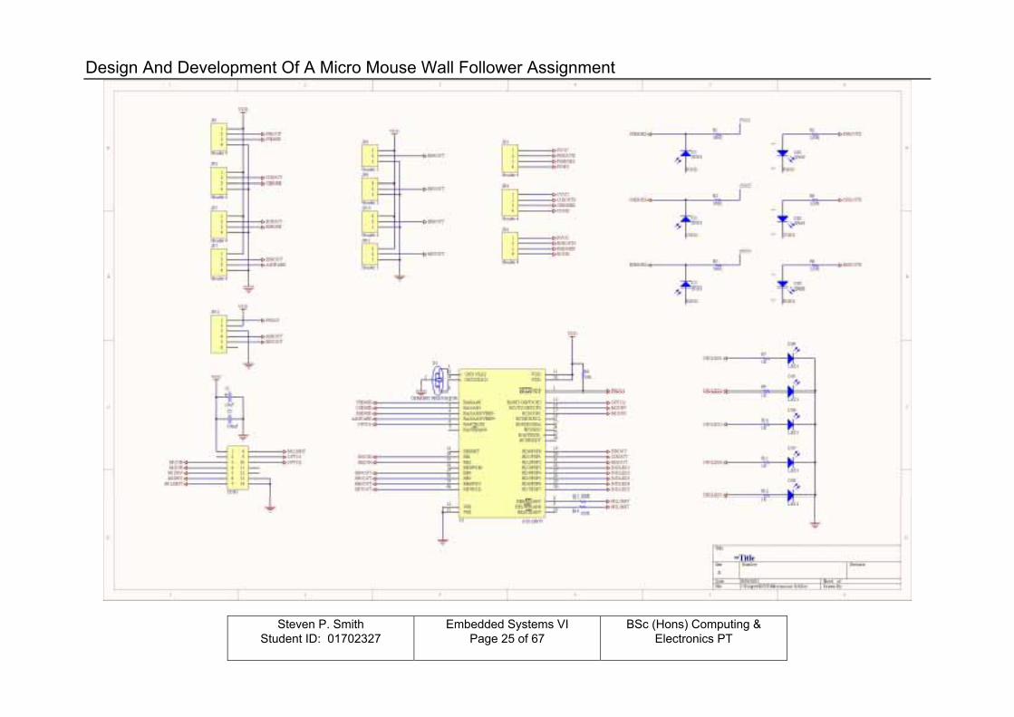
6.4 Additional Circuitry
The final addition to the circuit is the debugging LED arrangement. These LED�s are simply driven from spare outputs on the micro-controller and can be used by the software to indicate states to the user. The main use for the LED�s in our implementation is to show the measured distance from the wall after calculation, but is also used to show what mode the robot is in. For example when the robot is turning. The current limiting resistors have been chosen to reduce overall current consumption, but still give sufficient brightness during operation.
5V / 1000R = 5mA per LED
5 LED�s x 5mA = 25mA total consumption when all on
To avoid excessive current consumption careful operation of the LED�s should ensure that not all are operated simultaneously.
Design And Development Of A Micro Mouse Wall Follower Assignment
Steven P. Smith
Student ID: 01702327
Embedded Systems VI Page 25 of 67
BSc (Hons) Computing & Electronics PT

Design And Development Of A Micro Mouse Wall Follower Assignment
Steven P. Smith
Student ID: 01702327
Embedded Systems VI Page 26 of 67
BSc (Hons) Computing & Electronics PT
The circuit diagram shown previously was drawn using Protel DXP and after thorough visual checks were carried out, a net-list was built from the schematic layout. Once this has been generated a PCB layout can be implemented. To start the PCB layout Protel�s PCB wizard was used to choose the board size (x), the amount of layers (2, single layer was attempted but the auto router failed to route the board), and whether through-hole or surface mount components are to be used (through-hole). Once the PCB file has been created the first task is to modify the keep out layer to produce the odd shaped board that our application requires. The modified �keep-out� layer will prevent the auto router from laying tracks where we did not want them. The next task is to update the PCB file with the components from the schematic layout. This will produce a �rat�s nest� on the PCB layout which is simply all the required PCB footprints connected point to point ready for component placement. Care must be taken when the PCB footprints are placed on the board layout, to ensure that the PCB footprints have been chosen, and the correct pin layout is implemented, as we found out to our annoyance when building the board. The footprint chosen for the 14 pin header had a different pin configuration to the IDC connector required. This meant that the ribbon cable had to be directly soldered to the board rather that having the IDC socket mounted. Once the components are placed in their required positions the auto router can be started. The joy of the auto router is the speed in which the board can be routed (1-3 minutes using a reasonable spec PC ~500MHz). If the board produced is either unacceptable or cannot be routed because of component placement you can revert to the �rat�s nest�, adjust the component layout if necessary, and re-route. Once an acceptable board layout is produced, it can then be printed onto acetate sheet (top and bottom on separate sheets) ready for PCB production. The first attempt and final PCB layout, with silkscreen component layout is shown on the following pages. The first attempt was dropped, as it was decide by the group that there may be a requirement to remove the boards �ears� if the sensor system proved unsuitable. We could then implement the sensor system provided by Dr. Wilcox using the spare I/O mentioned earlier.

Design And Development Of A Micro Mouse Wall Follower Assignment
Steven P. Smith
Student ID: 01702327
Embedded Systems VI Page 27 of 67
BSc (Hons) Computing & Electronics PT
6.5 PCB Design � First Attempt Not to scale

Design And Development Of A Micro Mouse Wall Follower Assignment
Steven P. Smith
Student ID: 01702327
Embedded Systems VI Page 28 of 67
BSc (Hons) Computing & Electronics PT
6.6 PCB Design � Final Design Not to scale

Design And Development Of A Micro Mouse Wall Follower Assignment
Steven P. Smith
Student ID: 01702327
Embedded Systems VI Page 29 of 67
BSc (Hons) Computing & Electronics PT
7 PCB Build Phase To produce the Micro robot PCB the following process steps have been performed 7.1 Process Steps
1. Print layout art work to semitransparent 2. Apply semitransparent to the board 3. Expose board to ultraviolet ray 4. Etch board/clean 5. Drill
In order to produce the circuit design, time constraints involved with configuring the CAD software and defining libraries, had to be evaluated before the ultimate goal of printing the semi-transparent paper for board exposure could be successfully achieved. 7.2 Printing the Layout Several problems were experienced whilst attempting to print the circuit layout onto semitransparent paper and should be noted for future references. The semitransparent paper must be of rather good quality; this also requires that the printing technique is taken into consideration � for the purpose of this assignment a laser printer with a newly fitted toner was used at Gaydon Land Rover design and development centre. The developed schematic was saved as an Acrobat file and dissipated to all team members for assessment. The Acrobat Reader version originally used to print the transparencies failed to print the circuits to the correct dimensions; this was highlighted during the first test phase for the micro robot PCB. A later level of Acrobat Reader - version 5 � was later used. This enabled the "copies and adjustments" section from the print option window to be configured as shown below � please note the Acrobat Reader version previously used did not display this configurable option on the print window.
Acrobat print option window set-up
With the printing properties configured correctly, four board transparencies were produced for the next build stage.
Design And Development Of A Micro Mouse Wall Follower Assignment
Steven P. Smith
Student ID: 01702327
Embedded Systems VI Page 30 of 67
BSc (Hons) Computing & Electronics PT
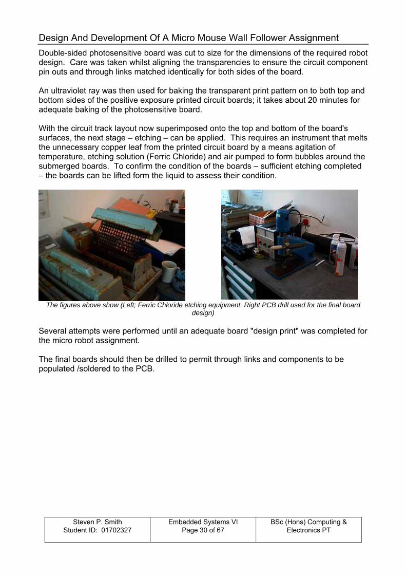
Double-sided photosensitive board was cut to size for the dimensions of the required robot design. Care was taken whilst aligning the transparencies to ensure the circuit component pin outs and through links matched identically for both sides of the board. An ultraviolet ray was then used for baking the transparent print pattern on to both top and bottom sides of the positive exposure printed circuit boards; it takes about 20 minutes for adequate baking of the photosensitive board. With the circuit track layout now superimposed onto the top and bottom of the board's surfaces, the next stage � etching � can be applied. This requires an instrument that melts the unnecessary copper leaf from the printed circuit board by a means agitation of temperature, etching solution (Ferric Chloride) and air pumped to form bubbles around the submerged boards. To confirm the condition of the boards � sufficient etching completed � the boards can be lifted form the liquid to assess their condition.
The figures above show (Left; Ferric Chloride etching equipment. Right PCB drill used for the final board
design) Several attempts were performed until an adequate board "design print" was completed for the micro robot assignment. The final boards should then be drilled to permit through links and components to be populated /soldered to the PCB.

Design And Development Of A Micro Mouse Wall Follower Assignment
Steven P. Smith
Student ID: 01702327
Embedded Systems VI Page 31 of 67
BSc (Hons) Computing & Electronics PT
8 Test sequence Boards created for the assignment undergo extensive test procedures before any interactions can be implemented. The following section will define each of the tests performed and purpose for their validity within the test specification. !! At no time shall the main PCB be connected to the motor drive assembly unless a PASS grade has been achieved by each of the endorsed test sequences defined below!! 8.1 Open circuit test Continuity tests shall be performed on all circuit links and connector bridging points detailed on the PCB schematic. 8.2 Short Circuit test Short circuit tests shall be performed on the PCB ONLY after "open circuit test data" has been successful achieved and a PASS grade is assigned for all test zones. Any deviations away from the specification shall be accessed and captured to their individually criticality before commencing the next subsequent test. All tracks shall be individually tested for insulation properties against all other non-related tracks. 8.3 Rectifications Any rectifications performed to the circuit board must be captured and documented to support future design phases, refer to Future Amendments. 8.4 Future Amendments Coincides with the Rectifications section, and details, which design elements requires revisiting should the next build phase be implemented. 8.5 Initial Board Test Condition
The two pictures above show the top and bottom conditions for the etched boards. Open and Short circuit tests are performed whilst the boards are in a component free state � as shown.

Design And Development Of A Micro Mouse Wall Follower Assignment
Steven P. Smith
Student ID: 01702327
Embedded Systems VI Page 32 of 67
BSc (Hons) Computing & Electronics PT
8.6 Test Definitions/Results The circuit board has been sectioned into test zones. Each zone shall depict the pins, which shall be tested during a particular test phase. At times tracks associated to the "pin under test" may terminate within an alternative zone; all pin circuits within the zone, which is under test, shall be tested till all possible connective arrangements have been investigated by the appropriate test phase. Any deviations, or pass/fail statuses MUST be captured. Only when all open and short tests have been completed and PASSED can the next test phase � in circuit component test - be applied. The following components were populated and soldered to the board:
• Micro carrier • Circuit resistors • Jumper connections and interface connectors
None populated components (These components shall be soldered to the board ONLY when all previous recommended actions have been successful completed).
• Infrared transmitting/receiving diodes • Resonator • Debugging LED's • Micro-controller
Open Circuit Tests TEST ZONE 1 2 3 4 5 6 7 Deviations None None None None None None None Pass/fail Pass Pass Pass Pass Pass Pass Pass Short Circuit Tests TEST ZONE 1 2 3 4 5 6 7 Deviations None None None None None None None Pass/fail Pass Pass Pass Pass Pass Pass Pass In Circuit Component Tests TEST ZONE
1
2
3
4
5
6
7
Deviations
None
None
None
Detected failures
associated to neighbouring zones- micro
interface
Pins
incorrectly assigned (con 1)
FCC68 footprint incorrect
Incorrect resistor values
Pass/fail Pass Pass Pass Fail Fail Fail Fail

Design And Development Of A Micro Mouse Wall Follower Assignment
Steven P. Smith
Student ID: 01702327
Embedded Systems VI Page 33 of 67
BSc (Hons) Computing & Electronics PT
8.7 Circuit Amendments Test Zone 4 Micro pin assignments to con 1 and FCC68 connector (JP12) incorrectly assigned � interface to motor board and ICD debugger FAIL - requires further investigation within test zones 5 & 6 Test Zone 5 Connector pins incorrectly assigned for the motor control circuit interface. Recommended action: Solder ribbon strip directly to PCB to allow correct interface connectivity + retest Test Zone 6 Footprint generated for connector type incorrect � connector type not supported within the software design component library. Recommended action: De-solder links from PCB, mount FCC68 connector and retrace terminals to specified pin allocations + retest. Test Zone 7 Resistor values incorrect for debug LED's, resistance measured 100 k ohm Recommended action: Replace with 1 k ohm resistors + retest

Design And Development Of A Micro Mouse Wall Follower Assignment
Steven P. Smith
Student ID: 01702327
Embedded Systems VI Page 34 of 67
BSc (Hons) Computing & Electronics PT
8.8 Test Zones
Test Zone 1 (Front sensor circuit)
Test Zone 2 (Centre and main sensor connectivity points)
Test Zone 3 (Rear sensors circuit)
Test Zone 4 (Micro interface)
Test Zone 5 (Board interface connection)
Test Zone 6 (Power control + ICD communications port)
Test Zone 7 (Debug circuitry)

Design And Development Of A Micro Mouse Wall Follower Assignment
Steven P. Smith
Student ID: 01702327
Embedded Systems VI Page 35 of 67
BSc (Hons) Computing & Electronics PT
8.9 Board Component Allocations
Above – Shows a semi-populated circuit board cut to shape. The grey connector was later removed – refer to in-circuit component test zone 5 for further information
Should all prior tests achieve a PASS status, or any deviations from the required specification be classified as acceptable then, and only then can the remaining components be soldered/placed to the PCB for validation. A simple software algorithm � next page - shall be coded to the micro to pulse each of the debugging LED's; this will verify ICD communication, resonator and LED/sensor circuit requirements. Transmitter and receiver sensor circuit's front, centre and rear shall be configured as output ports and pulsed in accordance with the debug LED's. A scope meter shall be used to ensure each test signal is detected within test zones 1, 2 and 3.

Design And Development Of A Micro Mouse Wall Follower Assignment
Steven P. Smith
Student ID: 01702327
Embedded Systems VI Page 36 of 67
BSc (Hons) Computing & Electronics PT
8.10 Test Algorithm
Start
Configure portsand set variables
number =0
Switch Micro portnumber HIGH
Wait for 2seconds
Switch Micro portnumber LOW
Wait for 2seconds
Increment portnumber
Is number>7
number =0
YES
NO

Design And Development Of A Micro Mouse Wall Follower Assignment
Steven P. Smith
Student ID: 01702327
Embedded Systems VI Page 37 of 67
BSc (Hons) Computing & Electronics PT
9 Final Assembly There are three main sub assembly units used in this project: The motor control assembly board and motors from the TIC.
The teams control and sensor board. The Nickel Cadmium battery pack as supplied by the college.

Design And Development Of A Micro Mouse Wall Follower Assignment
Steven P. Smith
Student ID: 01702327
Embedded Systems VI Page 38 of 67
BSc (Hons) Computing & Electronics PT
The controller board was added to the TIC�s motor assembly.
Next the power source (TIC�s battery pack) was added, creating a self-contained micro-mouse unit.

Design And Development Of A Micro Mouse Wall Follower Assignment
Steven P. Smith
Student ID: 01702327
Embedded Systems VI Page 39 of 67
BSc (Hons) Computing & Electronics PT
10 Controller - Software 10.1 Initial Software Structure Using the Ward-Mellor methodology, we drafted a context diagram giving an overview of the system and subsequent data and control flows we expected within the control architecture.
Micro MouseSystem
Left MotorControl
Right MotorControl
Port ControlRegisters
Front RangeSensor
Middle RangeSensor
Rear RangeSensor
Left_PWM
Left_Pulse
Left_Direction
Right_PWM
Right_Direction
Right_Pulse
Port ControlDataPWM Control
Data
Front_Sensor
Left_OverloadRight_Overload
Middle_Sensor
Rear_Sensor
Front_IR_Emitt-er Rear_IR_Emitter
Middle_IR_Emit-ter
In this application, the �Micro Mouse System� is equivalent to the software running within the 16F877 micro-controller and �Port Control Registers� its physical interface. The �Front, Middle and Rear Range Sensors� are the IR LED / IR Diode combinations used to detect an object and ascertain the distance to it. While the �Left and Right Motor Control� represent the motor assembly, including the control board , as supplied by the TIC.

Design And Development Of A Micro Mouse Wall Follower Assignment
Steven P. Smith
Student ID: 01702327
Embedded Systems VI Page 40 of 67
BSc (Hons) Computing & Electronics PT
Continuing the Ward-Mellor theme, a data flow diagram was generated to provide a more detailed outline of the functions that could be used for the control.
System Manager
1
Initalise
2
Voltage ToDistance(mm)Lookup Table
Motor Control
3
Sensor Decode
4
Fault Monitor
5
Straight LineControl
6
Turn LeftControl
7
Motor Operati-ng Parameters
Wall FollowerOr TurnSelector
8
Sensor_Data
Left_Pulse
Right_Pulse
Front_Sensor
Left_PWM
Left_Direction
Right_PWM
Right_Direction
Port ControlData
PWM ControlData
Left_Overload
Right_Overload
TInitialised
Middle_Sensor
Rear_Sensor
Voltage ToDistance(mm)
Front_IR_Emitt-er
Rear_IR_Emitter
Middle_IR_Emit-ter
E
E/D
E
Sensor_Data
Sensor_Data
Sensor_Data
Sensor_Data
Motor OperatingParameters
Motor OperatingParameters
Motor OperatingParameters
StraightOrTurn
T
E/D
E/D
Turn_Done
Fault
This is the proposed overall software organisation, with each process representing a function within the code.

Design And Development Of A Micro Mouse Wall Follower Assignment
Steven P. Smith
Student ID: 01702327
Embedded Systems VI Page 41 of 67
BSc (Hons) Computing & Electronics PT
The state diagram below models the code for the system manager control process, which is normally, and is true in this case, the main( ) function within a �C� program.
The function of this code is to �manage�, not to do. Therefore, it should be designed to co-ordinate the operation of sub-functions within a program, calling upon the relevant function to perform the necessary task. On completion of the task the sub-function reports back its completion by return back to the main( ) function, with or without data. The main( ) function will then determine which is the next action to be executed, either by sequence or decision based on data available. This does not consider interrupt routines as part of the sequence of events, has they are seen as an independent parallel function. Our only interest within this process is potentially the output from such an event, which would be represented by the contents of a variable.
ConfigureSystem
Drive MouseStraight
DetermineOperating Mode
Left Turn
END
Does It Needto Turn?
Is It In TheStart Position
Start-UpT: Initialise
"Initialised"E: "Sensor Decode"
E: "Wall FollowerOr Turn Selector"E: "Motor Control"
"StraightOrTur-n"=straight
E: "Straight Line Control"D: "Turn Left Control"
"StraightOrTur-n"=turn
E: "Turn Left Control"D: "Straight Line Control"
Check For Endof Wall
T: "Wall FollowerOr Turn Selector"
"Number Of CircuitsComplete"=true
D: "Motor Control"
"Turn_Done"=tr-ue
D: "Turn Left Control"
Repeat
"ReadyToStart"-=True
"ReadyToStart"-=False

Design And Development Of A Micro Mouse Wall Follower Assignment
Steven P. Smith
Student ID: 01702327
Embedded Systems VI Page 42 of 67
BSc (Hons) Computing & Electronics PT
The next phase of the Ward-Mellor process is to convert the previous diagrams into a Constantine diagram. This is a closer representation of the actual code.
MicroMouseSystem Manager
Initialise Fault Monitor Sensor DecodeWall Or Turn
Drive Straight Turn Corner
Motor ControlPWM ControllerPortConfiguration Motor Unit
Voltage ToDistance Table
Request_Init
Init_Done
Enable_MonitorFault Enable_Decode
Config_SetupnOut_Setup
Left_OL
Right_OL
Enable_Selector
Stop
Right_DirLeft_Speed
Left_Pulse
Right_Pulse
Sensor_Data
Sensor_Dat
Sensor_Data
Right_Dir
Left_Dir
Left_Speed
Right_Speed
Stop
Right_Dir
Left_Dir
Left_Dist
Right_Dist
Dist_Done
Stop
Enable_Straight
Stop
Enable_Turn
Turn_Done
Stop
mm_Value
Voltage_Value
However, there are limits to the CC5X compiler used for compiling the �C� code for programming the Microchips� 16F877 micro-controller. These include the amount of programme space available (8k reduced to 1k), and the levels that function calls can be nested.

Design And Development Of A Micro Mouse Wall Follower Assignment
Steven P. Smith
Student ID: 01702327
Embedded Systems VI Page 43 of 67
BSc (Hons) Computing & Electronics PT
Although the ideal system is to use the main( ) function in a supervisor manner, the previously explained limits affects our design, such that we need to produce a flatter structure. This reduces the need to load the stack, but does put a certain level of code back into the main( ) function.
Micro MouseSystem Mgr
I/O PortPWM Control
Voltage -Distance Table
Motor ControlRoutine
Sensor Decode
Motor ControlBoard
VoltageValue
mmValue
PortConfig
PWMConfig
Left_Speed
Right_Speed
Left-Fwd/Stop/Rev
Right-Fwd/Stop/Rev
Left_Dist
Right_Dist
FSense(Y/N) MSense(Y/N)RSense(Y/N)
FSense_Dist MSense_DistRSense_Dist
Left_PWM
Right_PWM
Left_Dir
Right_Dir
Right_Wheel_Pulse
Left_Wheel_Pulse

Design And Development Of A Micro Mouse Wall Follower Assignment
Steven P. Smith
Student ID: 01702327
Embedded Systems VI Page 44 of 67
BSc (Hons) Computing & Electronics PT
10.2 Calculating the PWM A PWM frequency of 10kHz was decided on from initial trials, which gave a good level of motor stability and resolution. The register PR2 contains the value that sets the PWM period for both of the CCP ports. The CCPR1L register along with bits CCP1X & CCP1Y contain the duty cycle for CCP1 port and CCPR2L, CCP2X and CCP2Y for CCP2 port, allowing a level of independent control.
This allows up to a 10 bit number to represent the duty cycle from 0 to 100%
prescaleTmrFoscPRPeriodPWM _24)12(_ ×××+=
(where Fosc represents the oscillators frequency) PWM frequency is defined as [1 / PWM period], which when substituted in the formula and it is transposed for PR2 results in:
1_2)/1(4
)_/1(2 −
××
=prescaleTmrFosc
FrequencyPWMPR
Example PWM frequencies and resolutions at 20MHz
PWM Frequency 1.22 kHz 4.88 kHz 19.53 kHz 78.12 kHz 156.3 kHz 208.3 kHz
Timer Prescaler (1,4,16) 16 4 1 1 1 1
PR2 Value 0xFFh 0xFFh 0xFFh 0x3Fh 0x1Fh 0x17h
Maximum Resolution (bits) 10 10 10 8 7 5.5
A Prescale value of 4 was chosen.
12414)20/1(4
)10/1(2 =−
××
=MHzkHzPR
Duty Cycle (bits) 9 8 7 6 5 4 3 2 1 0
CCPR?L
CC
P?X
CC
P?Y

Design And Development Of A Micro Mouse Wall Follower Assignment
Steven P. Smith
Student ID: 01702327
Embedded Systems VI Page 45 of 67
BSc (Hons) Computing & Electronics PT
To determine the range of values that can be used for the duty cycle, the resolution as to be calculated.
2log/_2)/1(
)_/1(log_
×
=prescaleTmrFosc
FrequencyPWMresolutionPWM
resolutionbitMHz
kHzresolutionPWM _99658.82log/4)20/1(
)10/1(log_ ≈=
×
=
Obviously if CCPR?L:CCP?X:CCP?Y are set to 0 then a 0% Duty Cycle is requested. A value of 500 will give a 100% Duty Cycle. 10.3 Developing The Code The code was broken down into 4 main areas, which were:
• initial setup/PORT configuration • system management • IR sensor feedback • drive function
It was decided quite early on to use mainly global data variables, rather local. This reduces the amount of data required to be passed between the different functions, especially interrupt routines, which is common to other areas of the code. For us this helped to simplify the code making it more readable, this is very important when developing code within a group. After the initial configuration, the main( ) function has two main roles. These are to sequence the sampling of the feedback values from the IR sensors, and based on the sensor values, control the output to the motors. The IR sensors feedback reading has two main constraints, which are only one analogue port can be active at any one time and two readings are required, first with the IR LED ON and secondly with the IR LED OFF. This generates the following sequence:
1. Configure front sensor�s analogue port AN0 and enable 2. Switch ON front IR LED 3. Wait time elapse 4. Read the value from analogue port AN0 5. Switch OFF front IR LED 6. Wait time elapse 7. Read the value from analogue port AN0 8. Subtract the two readings from each other to produce usable value 9. Configure middle sensor�s analogue port AN1 and enable 10. Switch ON middle IR LED 11. Wait time elapse 12. Read the value from analogue port AN1

Design And Development Of A Micro Mouse Wall Follower Assignment
Steven P. Smith
Student ID: 01702327
Embedded Systems VI Page 46 of 67
BSc (Hons) Computing & Electronics PT
13. Switch OFF middle IR LED 14. Wait time elapse 15. Read the value from analogue port AN1 16. Subtract the two readings from each other to produce usable value 17. Configure rear sensor�s analogue port AN2 and enable 18. Switch ON rear IR LED 19. Wait time elapse 20. Read the value from analogue port AN2 21. Switch OFF rear IR LED 22. Wait time elapse 23. Read the value from analogue port AN2 24. Subtract the two readings from each other to produce usable value 25. Repeat from step 1
This is achieved by using two nested counters. The first is a scan counter, �ScanCount�, that is used to sequence the events of configuring, IR LED control and reading the feedback value. The second counter, �SensorSeqr�, is used to poll between the front, middle and rear sensors. This changes the sequencer as below, but the functionality remains:
1. Configure sensor�s analogue port AN(SensorSeqr) and enable 2. Switch ON IR LED(SensorSeqr). 3. Wait time elapse. 4. Read the value from analogue port AN(SensorSeqr). 5. Switch OFF front IR LED(SensorSeqr). 6. Wait time elapse. 7. Read the value from analogue port AN(SensorSeqr). 8. Subtract the two readings from each other to produce usable value. 9. Increment SensorSeqr to next sensor, or if complete, back to first sensor. 10. Repeat from step1.
The tracking is processed each cycle of the program independently of the sensor processing routine. The sub functions included are:
• Motor control � This controls the direction and speed of the of the motors by setting the Duty Cycle.
• ConfigAnaloguePort � Depending on the SensorSeqr value, this will set-up the appropriate port.
• ReadIRDiode � Read the analogue value. • PulseIRLED � Use to set the state of the required infrared LED. • SetStatusLED � Sets the display LED�s to indicate the current process. These are
the micro-mouse�s position relative to the wall when tracking, or setting the two outer red and centre green LED�s ON to indicate it is turning.
Design And Development Of A Micro Mouse Wall Follower Assignment
Steven P. Smith
Student ID: 01702327
Embedded Systems VI Page 47 of 67
BSc (Hons) Computing & Electronics PT
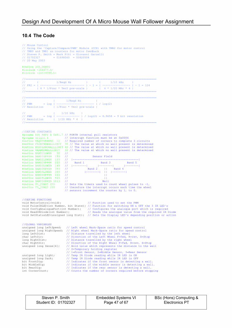
10.4 The Code // Mouse Control // Using the 'Capture/Compare/PWM' Module (CCP) with TMR2 for motor control // TMR0 and TMR1 as counters for motor feedback // Steven P. Smith = Mark Pitt = Giovanni Garzelli // 01702327 = 01698060 = 00820504 // 20 May 2003 #define ICD_DEBUG #include <16f877.h> #include <int16CXX.h> //================================================================================ // { 1/Reqd Hz } { 1/10 kHz } // PR2 = { --------------------------- } - 1 = { ----------------- } - 1 = 124 // { 4 * 1/Fosc * Tmr2 pre-scale } { 4 * 1/20 MHz * 4 } //================================================================================ //================================================================================ // { 1/Reqd Hz } // PWM = log { ----------------------- } / log(2) // Resolution { 1/Fosc * Tmr2 pre-scale } // { 1/10 kHz } // PWM = log { -------------- } / log(2) = 8.9658 = 9 bit resolution // Resolution { 1/20 MHz * 4 } //================================================================================ //DEFINE CONSTANTS #pragma bit RBPU @ 0x81.7 // PORTB internal pull resistors #pragma origin 4 // interrupt function must be at 0x0004 #define REQDCORNERS 12 // Required number of corners to complete 3 circuits #define FRONTNOWALLLIMIT 30 // The value at which no wall present is determined #define MIDDLENOWALLLIMIT 40 // The value at which no wall present is determined #define REARNOWALLLIMIT 30 // The value at which no wall present is determined #define BAND1LOWER 30 // #define BAND1UPPER 150 // Sensor Field #define BAND2LOWER 120 // |----------------------------------------| #define BAND2UPPER 200 // Band 1 Band 3 Band 5 #define BAND3LOWER 160 // |--------| |--------| |--------| #define BAND3UPPER 350 // Band 2 || Band 4 #define BAND4LOWER 300 // |--------| || |--------| #define BAND4UPPER 650 // || #define BAND5LOWER 500 // || #define BAND5UPPER 1023 // Wall #define T0_CONST 255 // Sets the timers used to count wheel pulses to -1, #define T1_CONST 255 // therefore the interrupt occurs each time the wheel // sensors increment the counter by 1, to 0. //DEFINE FUNCTIONS void MotorControl(void); // Function used to set the PWM void PulseIRLED(int Number, bit State); // Function for switching ON & OFF the 3 IR LED's void ConfigAnaloguePort(int Number); // Configures the analogue port which is required void ReadIRDiode(int Number); // Reads the analogue value from the required IR Diode void SetStatusLED(unsigned long Dist); // Sets the Display LED's depending position or action //GLOBAL VARIABLES unsigned long LeftSpeed; // Left wheel Mark-Space ratio for speed control unsigned long RightSpeed; // Right wheel Mark-Space ratio for speed control long LeftDist; // Distance travelled by the left wheel char LeftDir; // Direction of the Left Wheel F=fwd, R=rev, S=Stop long RightDist; // Distance travelled by the right wheel char RightDir; // Direction of the Right Wheel F=fwd, R=rev, S=Stop unsigned long Sense[4]; // Hold value which represents the distance to the wall // 0=Temporary holding register // 1=Front Sensor, 2=Middle Sensor, 3=Rear Sensor unsigned long Light; // Temp IR Diode reading while IR LED is ON unsigned long Dark; // Temp IR Diode reading while IR LED is OFF bit FrontDig; // Indicates if the front sensor is detecting a wall. bit MiddleDig; // Indicates if the middle sensor is detecting a wall. bit RearDig; // Indicates if the rear sensor is detecting a wall. int CornerCount; // Counts the number of corners required before stopping

Design And Development Of A Micro Mouse Wall Follower Assignment
Steven P. Smith
Student ID: 01702327
Embedded Systems VI Page 48 of 67
BSc (Hons) Computing & Electronics PT
unsigned Travelmode; // Tens 0x = No mode selected // 1x = Turn towards wall 10% // 2x = Turn towards wall 5% // 3x = Travel Straight // 4x = Turn away from wall 5% // 5x = Turn away from wall 10% // 6x = Left Turn // Units x0 --> x9 Steps within operation interrupt int_server(void) // interrupt function { int_save_registers // save status if (T0IF) // TMR0 overflow interrupt? { TMR0=T0_CONST; // Timer 0 register T0IF=0; // reset Timer 0 interrupt flag RightDist+=1; } if (TMR1IF) // TMR1 overflow interrupt? { TMR1H=255; TMR1L=T1_CONST; // Timer 1 register TMR1IF=0; // reset Timer 1 interrupt flag LeftDist+=1; } int_restore_registers // restore status } void main(void) { clearRAM(); // Set all of the variables to zero // Local variables for main routine unsigned long ScanCount; // Used to time slice events int SensorSeqr; // Used to sequence which sensor to sample, Front, Middle or Rear // Set up the required port ready for use // bits: 7654.3210 TRISD = 0b0000.0000; // Configure Port D bits 0-7 for output. TRISC = 0b0000.0000; // Configure Port C bits 0-7 for output. TRISB = 0b0011.0001; // Configure Port B bits for input/output. // Set up CCP ports mode of operation (PWM) // bits: 76.54.3210 CCP1CON = 0b00.00.1100; // bit 7,6 : Not Used CCP2CON = 0b00.00.1100; // bit 5,4 : PWM Duty cycle LSBs // bit 3,2,1,0: CCP mode selection (1100=PWM) // TIMER 2 CONFIGURATION // bits: 7.6543.2.10 T2CON = 0b0.0000.1.01; // bit 7 : Not Used // bit 6,5,4,3: Postscale // bit 2 : Timer On/Off // bit 1,0 : Prescale 1,4,16 // Set PWM PR2=124; // Overall value of 1 Duty cycle (ie 100%) // TIMER 0 CONFIGURATION (Pulse counter for Right hand wheel Opto) // bits: 7.6.5.4.3.210 OPTION = 0b0.0.1.0.1.000; // bit 7 : RBPU-Port B pull up resisters flag (N/A) // bit 6 : INTEDG-RB0/INT pin (N/A) // bit 5 : TOCS-Clk Source 0=Internal, 1=TOCKI // bit 4 : TOSE-Edge 0=Low-High, 1=High-Low // bit 3 : PSA-0=TMR0, 1=WDT Prescale Assignment // bits 2,1,0: PS0-2 Prescale (000=1:1 When using WDT)) TMR0 = T0_CONST; // Timer 0 register T0IE = 1; // enable TMR0 interrupt

Design And Development Of A Micro Mouse Wall Follower Assignment
Steven P. Smith
Student ID: 01702327
Embedded Systems VI Page 49 of 67
BSc (Hons) Computing & Electronics PT
// TIMER 1 CONFIGURATION (Pulse counter for Left hand wheel Opto) // bits: 76.54.3.2.1.0 T1CON = 0b00.00.0.0.1.1; // bits 7,6: Not used // bits 5,4: PreScaler, 00 = prescaler 1:1 // bit 3 : T1OSCEN-Oscillator enabled (when set to a 1) // bit 2 : T1SYNC-0=sync with external clock // bit 1 : TMR1CS-Clock source 0=int, 1=external // bit 0 : TMR1ON-enable timer (when set to a 1) TMR1H = 255; // Timer 1 High byte register (Preload with 255) TMR1L = T1_CONST; // Timer 1 Low byte register TMR1ON=1; // Timer 1 Enable TMR1IF=0; // reset Timer 1 interrupt flag TMR1IE = 1; // enable TMR1 interrupt PEIE = 1; // GIE = 1; // global interrupt enable // Delay to allow the ports to settle after initial configuration process unsigned long Delay; for(Delay=255;Delay>0;Delay--); //Set initial values LeftDist=0; LeftDir='S'; RightDist=0; RightDir='S'; LeftSpeed=0; RightSpeed=0; SensorSeqr=1; Travelmode=0; PulseIRLED(0,0); for(;;) // Loop forever { if(ScanCount==0)ConfigAnaloguePort(SensorSeqr); // Scan 0 - configure the req'd IR Diode port if(ScanCount==1)PulseIRLED(SensorSeqr,1); // Scan 1 - switch ON req'd IR LED if(ScanCount==498) // Scan 498 - read analogue value {ReadIRDiode(SensorSeqr); Light=Sense[0]; } if(ScanCount==499)PulseIRLED(SensorSeqr,0); // Scan 499 - switch OFF req'd IR LED if(ScanCount==998) // Scan 998 - read analogue value {ReadIRDiode(SensorSeqr); Dark=Sense[0]; } if(ScanCount==999) // Scan 999 - subtract the light & dark {Light=Dark-Light; // values to produce a reading which Sense[SensorSeqr]=Light; // considers ambient lighting and store } // against the appropriate sensor position FrontDig=0; // Reset front wall present variable, if(Sense[1]>=FRONTNOWALLLIMIT)FrontDig=1; // then set again if the wall is detected MiddleDig=0; // Reset front wall present variable, if(Sense[2]>=MIDDLENOWALLLIMIT)MiddleDig=1; // then set again if the wall is detected RearDig=0; // Reset front wall present variable, if(Sense[3]>=REARNOWALLLIMIT)RearDig=1; // then set again if the wall is detected if(Travelmode==0 && FrontDig==1) // If no mode and the front sensor is detecting the wall then {if(Sense[1]>BAND1LOWER && Sense[1]<BAND1UPPER)Travelmode=10; // depending on how close the if(Sense[1]>BAND2LOWER && Sense[1]<BAND2UPPER)Travelmode=20; // front sensor is to the wall, if(Sense[1]>BAND5LOWER && Sense[1]<BAND5UPPER)Travelmode=50; // the appropriate mode is set if(Sense[1]>BAND4LOWER && Sense[1]<BAND4UPPER)Travelmode=40; // which corresponds to the if(Sense[1]>BAND3LOWER && Sense[1]<BAND3UPPER)Travelmode=30; // required correction } if(MiddleDig==1 && Travelmode!=61 && FrontDig==0)Travelmode=70; // Approaching a corner, select // drive slow mode if(FrontDig==0 && MiddleDig==0 && RearDig==1)Travelmode=60; // Detected corner, select turn // corner mode if(Travelmode!=61 && FrontDig==0 && RearDig==0 && MiddleDig==0)Travelmode=0; // No wall detected, // Stop if(CornerCount==REQDCORNERS)Travelmode=0; // Stop once the req'd number of circuits have // been completed

Design And Development Of A Micro Mouse Wall Follower Assignment
Steven P. Smith
Student ID: 01702327
Embedded Systems VI Page 50 of 67
BSc (Hons) Computing & Electronics PT
if(Travelmode==0) // Stop mode {LeftDir='S'; // The left and right hand wheels have their direction set to 'S' LeftSpeed=0; // for stop and their PWM to 0. RightDir='S'; RightSpeed=0; } if(Travelmode==10) // Driving too far away from wall, servest correction {LeftDir='F'; // The left and right hand wheels have their direction set to 'F' LeftSpeed=130; // for forward. The left hand wheel PWM is set to the normal speed and RightDir='F'; // the right hand wheel PWM set to a higher value. RightSpeed=140; Travelmode=0; // The Travelmode is reset to 0 to allow a new mode to be selected } if(Travelmode==20) // Driving away from wall, correct {LeftDir='F'; // The left and right hand wheels have their direction set to 'F' LeftSpeed=130; // for forward. The left hand wheel PWM is set to the normal speed and RightDir='F'; // the right hand wheel PWM set to a higher value. RightSpeed=135; Travelmode=0; // The Travelmode is reset to 0 to allow a new mode to be selected } if(Travelmode==30) // On track drive straight {LeftDir='F'; // The left and right hand wheels have their direction set to 'F' LeftSpeed=130; // for forward. Both the left and right hand wheel PWM's are set to the RightDir='F'; // normal speed. RightSpeed=130; Travelmode=0; // The Travelmode is reset to 0 to allow a new mode to be selected } if(Travelmode==40) // Driving towards wall, correct {LeftDir='F'; // The left and right hand wheels have their direction set to 'F' LeftSpeed=130; // for forward. The left hand wheel PWM is set to the normal speed and RightDir='F'; // the right hand wheel PWM set to a lower value. RightSpeed=120; Travelmode=0; // The Travelmode is reset to 0 to allow a new mode to be selected } if(Travelmode==50) // Driving into wall, servest correction {LeftDir='F'; // The left and right hand wheels have their direction set to 'F' LeftSpeed=130; // for forward. The left hand wheel PWM is set to the normal speed and RightDir='F'; // the right hand wheel PWM set to a lower value. RightSpeed=110; Travelmode=0; // The Travelmode is reset to 0 to allow a new mode to be selected } if(Travelmode>=60 && Travelmode<=69) // Turn Left Routine {LeftDir='S'; // The left hand wheel's direction is set to 'S' to stop it along with LeftSpeed=0; // its PWM being set to 0. The right hand wheel has its direction set RightDir='F'; // to 'F' for forward travel with a PWM value. RightSpeed=120; Travelmode=61; // Travelmode is set to 61 to stop another selection until turn is complete if(Sense[1]>=BAND1LOWER) // Once the front sensor has detected the wall, the corners {CornerCount++; // turned count is incremented and the Travelmode is reset Travelmode=0; // to 0 to allow a new mode to be selected. } } if(Travelmode==70) // Travel slow, while the Middle Sensor passes the wall corner {LeftDir='F'; // The left and right hand wheels have their direction set to 'F' LeftSpeed=100; // for forward. Both the left and right hand wheel PWM's are set to RightDir='F'; // a slower speed than normal. RightSpeed=100; Travelmode=0; // The Travelmode is reset to 0 to allow a new mode to be selected } MotorControl(); // Unconditional call to the motor control function. if(FrontDig==1) // Call the display LED function using the front sensor {SetStatusLED(Sense[1]); // value while it is detecting the wall, otherwise use }else SetStatusLED(Sense[3]); // the rear sensors values. ScanCount++; // This section of code is used to sequence the events. The ScanCount if(ScanCount==1000) // is used to co-ordinate the reading of a sensor, while the SensorSeqr {ScanCount=0; // controls which sensor is to be processed. SensorSeqr++; } if(SensorSeqr>=4)SensorSeqr=1; // Once all have been processed, start at sensor 1 again. }// end of 'for' loop }// end of main()

Design And Development Of A Micro Mouse Wall Follower Assignment
Steven P. Smith
Student ID: 01702327
Embedded Systems VI Page 51 of 67
BSc (Hons) Computing & Electronics PT
void MotorControl(void) { unsigned long Temp; if(LeftDir=='S') {CCP1Y=0; // Reset CCP1's LSB bit 0 CCP1X=0; // Reset CCP1's LSB bit 1 CCPR1L=0; // Reset CCPR1L }else {CCP1Y=LeftSpeed.0; // Copy LeftSpeed LSB 0 to CCP1's LSB bit 0 CCP1X=LeftSpeed.1; // Copy LeftSpeed LSB 1 to CCP1's LSB bit 1 Temp=LeftSpeed/4; // Shift LeftSpeed 2 to the right to loose LSB's already CCPR1L=Temp; // copied, copying the remaining LeftSpeed to CCPR1L } if(LeftDir=='R') // If reverse direction is requested then the output is set to {PORTB.1=1; // reverse the polarity to the motor, otherwise reset the output. }else {PORTB.1=0; } if(RightDir=='S') {CCP2Y=0; // Reset CCP2's LSB bit 0 CCP2X=0; // Reset CCP2's LSB bit 1 CCPR2L=0; // Reset CCPR2L }else {CCP2Y=RightSpeed.0; // Copy RightSpeed LSB 0 to CCP2's LSB bit 0 CCP2X=RightSpeed.1; // Copy RightSpeed LSB 1 to CCP2's LSB bit 1 Temp=RightSpeed/4; // Shift RightSpeed 2 to the right to loose LSB's already CCPR2L=Temp; // copied, copying the remaining RightSpeed to CCPR2L } if(RightDir=='R') // If reverse direction is requested then the output is set to {PORTB.2=1; // reverse the polarity to the motor, otherwise reset the output. }else {PORTB.2=0; } }// End of motor control function void PulseIRLED(int Number, bit State) {if(Number==0) // Used to turn OFF all of the IR LED's {PORTD.0=0; PORTD.1=0; PORTD.2=0; } if(Number==1)PORTD.0=State; // Set the front IR LED to the required state. if(Number==2)PORTD.1=State; // Set the middle IR LED to the required state. if(Number==3)PORTD.2=State; // Set the rear IR LED to the required state. }// End of pulse IR LEDs function void ConfigAnaloguePort(int Number) { // ADCON0 bit representation // bits 7,6 : A/D Conversion clock selection (10=Fosc/32) // bits 5,4,3: Port select (000=AN0, 001=AN1, 010=AN2) // bit 2 : A/D status (1=Running, 0=Stopped) // bit 1 : Not Used // bit 0 : Enable ADC (when set to a 1) // bits: 76.543.21.0 if(Number==1)ADCON0 = 0b.11.000.00.1; //Port AN0 selected if(Number==2)ADCON0 = 0b.11.001.00.1; //Port AN1 selected if(Number==3)ADCON0 = 0b.11.010.00.1; //Port AN2 selected // bits: 7.654.3210 ADCON1 = 0b.0.000.0000; // bit 7 : A/D Results Format (0=left justify, 1=Right justify) // bits 5,4,3 : Not Used // bits 3,2,1,0: Configures the ports as digital or analogue // (0000=all 8 enabled as analogue) }// End of Analogue Port Configuration void ReadIRDiode(int Number) { GO=1; // Start conversion while(GO); // Wait until complete Sense[0]=(unsigned long)ADRESH*256; // Copy ADRESH to High byte Sense[0]=Sense[0]+ADRESL; // Copy ADRESL to Low byte Sense[0]=Sense[0]/64; // Move right 6 positions }// End of Read IR Diode function

Design And Development Of A Micro Mouse Wall Follower Assignment
Steven P. Smith
Student ID: 01702327
Embedded Systems VI Page 52 of 67
BSc (Hons) Computing & Electronics PT
void SetStatusLED(unsigned long Dist) { PORTD.3=0; // All the LED's are turned OFF. PORTD.4=0; PORTD.5=0; PORTD.6=0; PORTD.7=0; if(Dist>BAND1LOWER && Dist<BAND1UPPER)PORTD.7=1; // Depending on the distance to the wall if(Dist>BAND2LOWER && Dist<BAND2UPPER)PORTD.6=1; // then the appropriate display LED's are if(Dist>BAND3LOWER && Dist<BAND3UPPER)PORTD.5=1; // set ON. if(Dist>BAND4LOWER && Dist<BAND4UPPER)PORTD.4=1; if(Dist>BAND5LOWER && Dist<BAND5UPPER)PORTD.3=1; if(Travelmode>=60 && Travelmode<=69) // If the unit is turning, then set the two {PORTD.7=1; // outer and the middle display LED's to PORTD.5=1; // indicate the function being processed. PORTD.3=1; } }// End of Display LED’s Setting function
The final software version as evolved with our knowledge and experience through the development of this project, hence the reason for some of the deviations to plan.
The code was successfully compiled and loaded into the micro-controller. Note the number of words used is 915. Although the 16F877 as 8k available the �free� version of software we were using (CC5X), limited us to 1k.

Design And Development Of A Micro Mouse Wall Follower Assignment
Steven P. Smith
Student ID: 01702327
Embedded Systems VI Page 53 of 67
BSc (Hons) Computing & Electronics PT
11 Commissioning The programme was down loaded into the micro-controller, ready for the trial run around the maze.
For the first outing things looked quite promising, but bugs did exist: A few typing errors The wall sensor band limits had to be altered, the white gloss surface of the maze produced a different performance to our initial values. We moved the sensors away from the wall in 5mm increments building a new table of values, and then adjusted the values accordingly The micro-mouse over travelled the corners, resulting in it hitting the wall ahead, totally loosing detection of the wall or causing it to practically turn into the wall, making the recovery harder. For this we added a new slow forward travel mode. This was active when the front sensor was not detecting a wall, but the middle and rear sensors were. The motor speed values required changing. Initially
the software changed the outer wheel with regard to the error to a slower speed. After advice a few experiments we found that it was better to leave on motor at the running speed, and alter the other up or down depending on the error detected.

Design And Development Of A Micro Mouse Wall Follower Assignment
Steven P. Smith
Student ID: 01702327
Embedded Systems VI Page 54 of 67
BSc (Hons) Computing & Electronics PT
So after a few adjustments, trials and tribulations we were ready. And finally it worked, trundling down the straights and swinging around the corners. A very satisfying moment for the team.

Design And Development Of A Micro Mouse Wall Follower Assignment
Steven P. Smith
Student ID: 01702327
Embedded Systems VI Page 55 of 67
BSc (Hons) Computing & Electronics PT
12 Conclusion (Observations/Lessons Learnt) We have achieved the project criteria of producing a left hand wall follower, capable of negotiating the external wall of a rectangle. This has been the result of good teamwork, planning and perseverance. It has been a very enlightening project, giving rise to many different problems and solutions, not always obvious at the time, has discussed below. In the end did not use the wheel pulse detection, instead decided to use the IR sensors only. We reasoned that this would indicate the tracking error and when the mouse had completed a left hand turn. We had applied the K.I.S.S. principle (Kept It Simple, Stupid), which inadvertently solved a problem we had, that we did not realise at the time. This is wheel slip. The rear balance support affects the performance of the mouse by creating resistance to movement (friction). What we saw was the right hand wheel was turning, but the mouse did not move when attempting a left hand turn.
To remedy this problem, we manufactured a new support. This was a �L� bracket with a 10mm hole drill in it to locate a 11mm ball bear. The ball is held in place with an industrial two-part glue. From the initial trials conducted, it has appeared to significantly improve the situation.
Although materials such as metals and plastics may have a low co-efficiency of friction, if the material is soft, it will ware quickly, damaging its surface. With the potential grooves worn into the surface increasing the friction (and even �stiction� when pulling off i.e. resistance to the initial parting of surfaces), then this can cause a higher friction between the rear support and the running surface than that of the wheel and the running surface, resulting in wheel slippage. We believe the ball bearing offers a low co-efficiency of friction due to the surface finish, along with resistance to damage due to its hardened surface. Remember the problem. It was very easy to loose sight of the fact that all we had to do was navigate around a square/rectangle three times, following the wall to the left of the Micro Mouse unit.

Design And Development Of A Micro Mouse Wall Follower Assignment
Steven P. Smith
Student ID: 01702327
Embedded Systems VI Page 56 of 67
BSc (Hons) Computing & Electronics PT
Although we got the X-Y dimensions sorted for the position of the sensors, we forgot the Z dimension, which resulted in the improvised positioning. With the sensors suspended underneath like this, it resulted in them being susceptible to movement and damage. The change would be to mount them directly on to a PCB board, which is mounted vertically along the side of the unit, with added mechanical protection. The mark I Micro-mouse as produced what I believe to be a good foundation on which mark II can be developed. The main change would be the addition of more sensors, however not all of them would be analogue. From the usage of the sensors in mark I, only the front side sensor needed to be analogue as the other two were used as digital events, wall present/not present. The additional �Ahead� sensor would be analogue with a preceived three bands, �No Wall Present�, �Wall Present -Travel Slow� and �Stop�.
Feedback
System Manager
LH Rear Sensor
Right Hand Drive Unit
Feedback
Left Hand Drive Unit
LH Front Sensor
LH Middle Sensor
Band 1
Band 2
Band 3
Band 4
Band 5
RH Rear Sensor
RH Middle Sensor
RH Front Sensor
AheadSensor
Wall Present
No Wall Present No Wall Present
Wall Present
No Wall Present
Wall Present
No Wall Present
Wall Present
No Wall Present
Band 1
Band 2
Band 3
Band 4
Band 5
No Wall Present
Wall Present (Slow) Stop
No
Wal
l Pre
sent

Design And Development Of A Micro Mouse Wall Follower Assignment
Steven P. Smith
Student ID: 01702327
Embedded Systems VI Page 57 of 67
BSc (Hons) Computing & Electronics PT
The infrared sensors used in a digital fashion, would connect as shown in the diagram, using either an IR Diode or Phototransistor. Although this will require additional circuitry, it does remove the code required to process the data through an analogue port, and save an output for driving an indication LED. To navigate through a full maze, then the wheel feedback would be required. However, from the lessons already stated, then care must be taken to ensure false information is minimised. To achieve this I propose the third support to be a rotating ball (as in a PC mouse), and change the wheels to slightly wider, flat tyre type.
LM324PhotoTransistor
InfraredDiode
IndicationLED
220R 10k
470R
20k
SENSOR 1
VCC
Circuit shown using a Phototransistor

Design And Development Of A Micro Mouse Wall Follower Assignment
Steven P. Smith
Student ID: 01702327
Embedded Systems VI Page 58 of 67
BSc (Hons) Computing & Electronics PT
APPENDIX A - Original Specification Document The Course The course that the wall-follower must negotiate is to be 4 squares by 4-squares of the existing micromouse maze, with a total of 3 circuits of the so-formed rectangle. The groups will be given 3 runs, with the time of the best run being used to determine a winner. The Task: Design and develop a Wall-Follower, and present a formal report describing the design, construction and test phases. 1. First things first ..... prepare a block diagram showing the partitioning of the problem into a number of smaller, self-contained, and more easily understood tasks. This serves to not only remind you of what the assignment was about, but should also shock you into realising how little you have done on any of the major topic areas, and how little you actually know about any topic area at all (including partitioning of a problem). 2. Identify known material relevant to each topic, and reference this material in an effort to ‘flesh-out’ the report. In this way you should be able to differentiate between what you have been given, and what you have to do (or should have done) for yourselves. Put a lot of effort into ignoring the urge to ‘run-away.... run-away....”. 3. When you have run out of references, the bits left un-annotated are the bits that you actually have to WORK on. 4. Add sufficient detail to these bits to enable you to attempt a reasonable defence of your claim that: “ ...you were the only one doing any work in your group....” 5. Present a summary/conclusion that says what a brilliantly designed lab this was, how much you enjoyed it, and what a pleasure it will be to come back next year and do it again.

Design And Development Of A Micro Mouse Wall Follower Assignment
Steven P. Smith
Student ID: 01702327
Embedded Systems VI Page 59 of 67
BSc (Hons) Computing & Electronics PT
Some breakdown such as that above will clearly define the sections to the report. Reference sections should be mainly appendices. The main elements of the report will be the controller hardware and software – however, the other areas indicated MUST be discussed in some detail. The report should be a balanced discussion of all areas of the design and implementation of a wall-follower.
Wall-Follower
Drive System Sensors Controller Power Source
Robotic V1.5DocumentationPhysical Dimensions & CalculationsPWM, Direction etc.
Reference Assignment 2 –but with specificreference to the enddesign
Battery Voltage,Capacity, Surge Current capability,max discharge rateetc.
Hardware Software
Microcontroller
Support Circuitry
Interfacing requirements
Wall sensorsWheel SensorsPWMControl loopBattery conditionetc. etc.

Design And Development Of A Micro Mouse Wall Follower Assignment
Steven P. Smith
Student ID: 01702327
Embedded Systems VI Page 60 of 67
BSc (Hons) Computing & Electronics PT

Design And Development Of A Micro Mouse Wall Follower Assignment
Steven P. Smith
Student ID: 01702327
Embedded Systems VI Page 61 of 67
BSc (Hons) Computing & Electronics PT
APPENDIX B � Example Nickel-Cadmium Rechargeable Battery Data Sheet Although this not the battery used, the characteristics are similar, and so it can be used for reference purposes.

Design And Development Of A Micro Mouse Wall Follower Assignment
Steven P. Smith
Student ID: 01702327
Embedded Systems VI Page 62 of 67
BSc (Hons) Computing & Electronics PT
APPENDIX C � Example Nickel-Metal Hydride Rechargeable Battery Data Sheet

Design And Development Of A Micro Mouse Wall Follower Assignment
Steven P. Smith
Student ID: 01702327
Embedded Systems VI Page 63 of 67
BSc (Hons) Computing & Electronics PT
APPENDIX D � Example Alkaline Non-Rechargeable Battery Data Sheet

Design And Development Of A Micro Mouse Wall Follower Assignment
Steven P. Smith
Student ID: 01702327
Embedded Systems VI Page 64 of 67
BSc (Hons) Computing & Electronics PT

Design And Development Of A Micro Mouse Wall Follower Assignment
Steven P. Smith
Student ID: 01702327
Embedded Systems VI Page 65 of 67
BSc (Hons) Computing & Electronics PT
APPENDIX E � Glossary Of Battery Terms
Active Material Specific chemically reactive material at the positive or negative electrode that takes part in the charge and discharge reactions.
Air Cell Battery system, which utilizes oxygen in combination with, catalysed carbon as the cathode and zinc as the anode to produce electricity.
Alkaline Battery Primary battery, which employs alkaline aqueous solution for its electrolyte.
Ampere-Hours Product of current (amperes), multiplied by time (in hours) the circuit is closed (current flowing).
Anode The negative electrode. The electrode at which an oxidation reaction (loss of electrons) occurs.
ANSI American National Standards Institute sponsored by NEMA, National Electric Manufacturers Association and cover cell sizes, terminals and testing procedures.
Average Drain The average current withdrawn from a cell or battery during discharge; usually approximated by calculating the current at 50% depth of discharge.
Battery Technically, a battery consists of two or more series or parallel connected galvanic cells. Frequently, however, a single cell is called a battery.
Button Cell See miniature battery Capacity Output capability over a period of time; expressed in ampere-hours.
Carbon Zinc A generic term for primary dry batteries of the LeClanche or Zinc Chloride systems.
Cathode The positive electrode. The electrode at which a reduction reaction (gain of electrons) occurs.
Cell A primary galvanic unit, which converts chemical energy directly into electric energy. Typically consists of two electrodes of dissimilar material isolated from one another electronically in a common ironically conductive electrolyte.
Cell Reversal Reversing polarity of terminals of a cell or battery due to over-discharge.
Charge, State of Condition in terms of the rated capacity remaining at a given point in time.
Charging Process of supplying electrical energy for conversion to stored chemical energy.
Closed-circuit voltage (CCV)
Voltage as measured of a cell or battery under a specific discharge load and time interval.
Coin Cell See miniature battery
Collector Electronic connection between the battery electrode and the external circuit.
Constant Current Charging or discharging method in which current does not change appreciably in magnitude regardless of battery voltage or temperature.

Design And Development Of A Micro Mouse Wall Follower Assignment
Steven P. Smith
Student ID: 01702327
Embedded Systems VI Page 66 of 67
BSc (Hons) Computing & Electronics PT
Constant Power Power remains stable regardless of battery voltage. As battery voltage changes, the current is adjusted to maintain targeted power value. (See below for power definition.)
Constant Resistance Commonly found in devices, which maintain a constant resistance throughout the battery discharge. As the battery is drained, both voltage and current decline.
Continuous Test Regimen Charge and/or discharge profile that is defined without rest periods.
Cut-off Voltage Voltage at the end of useful discharge. Battery voltage below, which the connected equipment will not operate or below which operation is not recommended.
Cycle One sequence of activity. This can be a pulse or continuous drain.
Cylindrical Battery A battery whose height is greater than its diameter. The term cylindrical is also used to describe batteries made up of cylindrical cells.
Deep Discharge Discharge of the battery to below the specified voltage cut-off before the battery is replaced or recharged.
Depth of Discharge (DOD) The percent of rated capacity to which a cell or battery is discharged.
Discharge Withdrawal of electrical energy from a cell or battery, usually to operate connected equipment.
Discharge Rate The current at which a cell or battery is discharged. Drain Withdrawal of current from a cell or battery.
Drain, Heavy Generally, current that would discharge a battery within one day at room temperature.
Drain, Light Generally, current that would discharge a battery after one month at room temperature.
Drain, Moderate Current that would discharge a battery in approximately one week at room temperature.
Dry Battery A battery in which the electrolyte is immobilized, being either in the form of a paste or gel or absorbed into the separator material.
Duty Cycle The time duration and use frequency during which a battery is drained (i.e. 2 hours/day).
Electrode Conducting body at which the electrochemical reaction occurs.
Electrolyte May be solid or liquid. Usually an aqueous salt solution that permits ionic conduction between the positive and negative electrodes
Energy Output capability; ampere-hour capacity times average closed-circuit discharge voltage, expressed as watt-hours.
Energy Density Ratio of battery energy to weight or volume (watt-hours per kilogram or watt-hours per cubic centimetre).
Functional End Point (FEP)
Voltage below which battery-operated equipment will not function properly.
IEC International Electrochemical Commission. A worldwide organization for standardization in the electrical and electronic fields.
Impedance (Z) The total opposition that a battery offers to the flow of alternating current. Impedance is a combination of resistance and reactance.

Design And Development Of A Micro Mouse Wall Follower Assignment
Steven P. Smith
Student ID: 01702327
Embedded Systems VI Page 67 of 67
BSc (Hons) Computing & Electronics PT
Initial Drain Current that a cell or battery supplies when first placed on load. Also referred to as starting drain.
Internal Resistance (Ri) Opposition to direct current flow within a battery, with the battery as source, causing a drop in closed-circuit voltage proportional to the current drain from the battery.
Intermittent Test Regimen
Charge and/or discharge profile that is defined with specified rest periods.
LeClanche A Carbon Zinc battery with slightly acidic electrolyte consisting of ammonium chloride and zinc chloride in water.
Miniature Battery A button or coin shaped battery whose diameter is greater than its height. The term "Miniature" is also used to describe batteries made up of miniature cells.
Open-Circuit Voltage (OCV)
The no load voltage of a cell or battery measured with a high resistance voltmeter.
Polarization Electrical potential reduction of electrodes typically arising from prolonged or rapid discharge of the battery.
Primary A cell or battery designed to deliver its rated capacity once and be discarded; not designed to be recharged.
Rated Capacity The average capacity delivered by a cell or battery on a specified load and temperature to a voltage cutoff point, as designated by the manufacturer; usually an accelerated test approximating the cell or battery�s capacity in typical use.
Rate Sensitivity Typically refers to battery performance under various discharge loads with operating voltage being the defining characteristic
Rating Drain The specified current withdrawn form a cell or battery to determine its rating capacity.
Rechargeable Capable of being recharged; refers to secondary cells or batteries. Secondary A cell or battery designed to be recharged. Self Discharge Rate The rate at which a cell or battery loses its capacity when standing idle.
Service Maintenance The percent of fresh rated capacity remaining after a specified period of time.
Shelf-Life The amount of time a cell or battery will retain a specified percent of its rated capacity, typically under ambient storage conditions.
Silver Oxide Battery containing cathode of silver oxide, anode of zinc and highly alkaline electrolyte consisting of NaOH or KOH.
Trickle Charge A method of recharging in which a secondary battery is either continuously or intermittently connected to a constant current supply that maintains the battery in a fully or near full charged condition.
Zinc Air See Air Cell
Zinc Chloride A Carbon Zinc battery with a slightly acidic electrolyte consisting mainly of zinc chloride in water.


![Eee Vi Embedded Systems [10ee665] Notes](https://static.fdocuments.us/doc/165x107/577c7b3f1a28abe054979996/eee-vi-embedded-systems-10ee665-notes.jpg)
