Embedded Systems - IRISA · Sino French Laboratory of Informatics, Automation and Applied...
21
Sino French Laboratory of Informatics, Automation and Applied Mathematics Full System Simulation of Embedded Systems Vania JOLOBOFF INRIA FORMES Project at Tsinghua University Beijing, CHINA Xi'An NWPU Presentation 2 Embedded Systems Industrial Objectives Improve reliability and safety of embedded systems (HW + SW) Lower time to market with shorter validation cycle Full System Simulation 3
Transcript of Embedded Systems - IRISA · Sino French Laboratory of Informatics, Automation and Applied...

Sino French Laboratory of Informatics, Automation and Applied Mathematics
Full System Simulation of Embedded Systems
Vania JOLOBOFFINRIA
FORMES Project at Tsinghua University Beijing, CHINA
Xi'An NWPU Presentation 2
Embedded Systems
Industrial Objectives
Improve reliability and safety of embedded systems (HW + SW) Lower time to market with shorter validation cycle
Full System Simulation 3

Model Driven Engineering Chain
Validation/Verification is one step in the model driven engineering chain, but a critical one for products validation and certification
Full System Simulation 4
Others Model
Use Case Model
HW Functional Model
UML, AADL, B, etc
Software manually handcoded or tool generated
Hardware manually designed or generated
Simulation Verification
ProductSW Model
MathLab, Simulink, MAPLE, etc
Different types of Simulation
Mathematical / Physical Model SimulationExtremely valuable in the design/exploration phase to experiment new methods and algorithms
MathLab, Simulink
Hardware / Software SimulationDifferent types of simulation according to the goals
Verify the hardware design (VHDL ) : simulate the hardware at clock/gate and pin levelVerify the architecture and the software : simulate the hardware behavior with accuracy with respect to software, which does not mean simulate every hardware detail
5Full System Simulation
HW+SW Full System Simulation
Run the entire embedded application software over simulated hardware
CHALLENGE : With identical behavior and performance, at low cost
Analogy flight simulator
Full System Simulation 6
Application Software
running on Hardware Simulation
Flight SimulatorInput Control

Advantage of Full System Simulation
Software development can take place before the hardware is ready, therefore validation is fasterValidation is less costly and faster because many engineers can run validation tests on a PC instead of sharing a few HW prototypes.Some things can be done with simulation that can hardly be done with hardware
Verifying correct hardware initialization, simulating defective hardware, internal observations, etc.
Simulation tools can be connected with formal methods tools
Full System Simulation 7
Simulation Speed
Example SPEC INT 2000 Test Suite6 trillions instructionsOn a 3 GHz PC: 2000 seconds ~ 33 minutesOn a 3 Mips simulator 2,000,000 seconds ~ 70 days
Other examplesA program running in 1 second on a 3 GHz host runs in 50 minutes if simulated at 1 Mips.Simulating at 300+ Mips on a 3 GHz host means each target machine instruction is simulated with less than 10 instructions in the simulator host engine.
8Full System Simulation
Simulation Hardware Abstraction Level
Programmers’ View Untimed (Bit Accurate): The simulator implements the HW specification
as given to the SW developer. No timing is provided
Programmers’ View Timed : Same as untimed, but in addition provided estimated
timing for operations
Clock Cycle Accurate: the simulation is 100% accurate at signal level for each clock tick.
Register Transfer Level : emulation of the real hardware bit/pin level
Larger and slower
Smaller and faster
Unable to achieve > 10 Mips
Only way to achieve >100 Mips
9Full System Simulation

Full System Simulation 10
Full System Simulation : What is the good model ?
From the software point of viewSimulation must be fast enough to run the programs in a few minutes, possibly hours for very long sessions but not days…Simulation must be complete, must not validate one piece of software independently from the others
Because the problems come from integration…From the hardware point of view
Simulation must be as accurate as possibleCalibration of hardware throughput is importantIntegration of third party models must be possible
Full System Simulation 11
Simulation accuracy and speed
Ideal: to obtain 100% accuracy with real-time simulation speed. Embedded system real time 300 – 500 Mips
Cycle accurate HW models (VHDL) are much too slow for software validation…
Need higher level of abstraction
你是要快还是要准确?
Simulation requires standards
It is hard to build a complete system simulator from scratch
Many components, some of them very complexNecessity to re-use existing models
From corporate databases and librariesFrom Third-Parties
This can only be achieved if there are standard interfaces between the components
Full System Simulation 12
Simulation EngineSimulation Engine
Components from Party BComponents from Party B
New componentsNew components
Components from Party AComponents from Party A

Two standards for interoperability
SystemC : Simulate a set of hardware componentsTLM : Communication between components
Full System Simulation 13
SystemC in one lesson
Hardware components are elements working simultaneously (parallel) communicating through some wiring
SystemC (IEEE standard 1666) provides for simulation of parallel hardware components
ProcessorProcessor MemoryMemory Ethernet ControllerEthernet
ControllerGraphics ControllerGraphics Controller
USB Controller
USB Controller
BusBus
14Full System Simulation
SystemC in one lesson (2)
SystemC fundamental conceptsRepresentation
MODULE to implement a component (which may contain other MODULEs / componentsPORT to implement a communication point
ControlSC_THREAD to simulate parallel processessc_start() to start the simulation after all modules have been constructedsc_wait() to wait for something (time, event,…)sc_notify() to signal an eventA scheduler to schedule threads according to an algorithm described in the standard
15Full System Simulation

SystemC threads and scheduler
Processor
SC_THREAD do {Exec_instr()sc_wait(flag1);}
Processor
SC_THREAD do {Exec_instr()sc_wait(flag1);}
Ethernet Controller
SC_THREADdo {Process_network_packet();Notify_packet_arrived();sc_wait(flag2);}
Ethernet Controller
SC_THREADdo {Process_network_packet();Notify_packet_arrived();sc_wait(flag2);}
Graphics Controller
SC_THREADdo {Process_graphics_request();sc_wait(flag3);}
Graphics Controller
SC_THREADdo {Process_graphics_request();sc_wait(flag3);}
SystemC schedulerSystemC scheduler
16Full System Simulation
SystemC Use Cases
SystemC can be used for Bit accurate simulationCycle accurate simulationCycle accurate simulation with hardware synthesis
using a specific subset
Full System Simulation 17
SystemC scheduling
Algorithm steps through so called Delta-cycles that execute in no time
1. Initialization Phase2. Evaluate Phase: From the set of processes that are ready to run, select a process and resume its execution. The order in which processes are selected for execution from the set of processes that are ready to run is unspecified. The execution of a process may cause immediate event notifications to occur, possibly resulting in additional processes becoming ready to run in the same evaluate phase.3. Repeat step 2 for any other processes that are ready to run.4. Update Phase: Execute any pending calls to update() from calls to the request update() function executed in the evaluate phase.5. If there are pending delta-delay notifications, determine which processes are ready to run and go to step 2.6. If there are no more timed event notifications, the simulation is finished.7. Else, advance the current simulation time to the time of the earliest (next) pending timed event notification.8. Determine which processes become ready to run due to the events that have pending notifications at the current time. Go to tep 2.
Or the simulation stops by calling stop function.Full System Simulation 18
Communication Interface
Java Style Example
class Drawable { … getResolution() … }
interface Printable { … print (Drawable d) …
}
class Rectangle implements Printable {print(d) { print a rectangle on drawable d}
class Circle implements Printable {}print(d) { print a circle on drawable d}
RequireProvide
19Full System Simulation
Full System Simulation 20
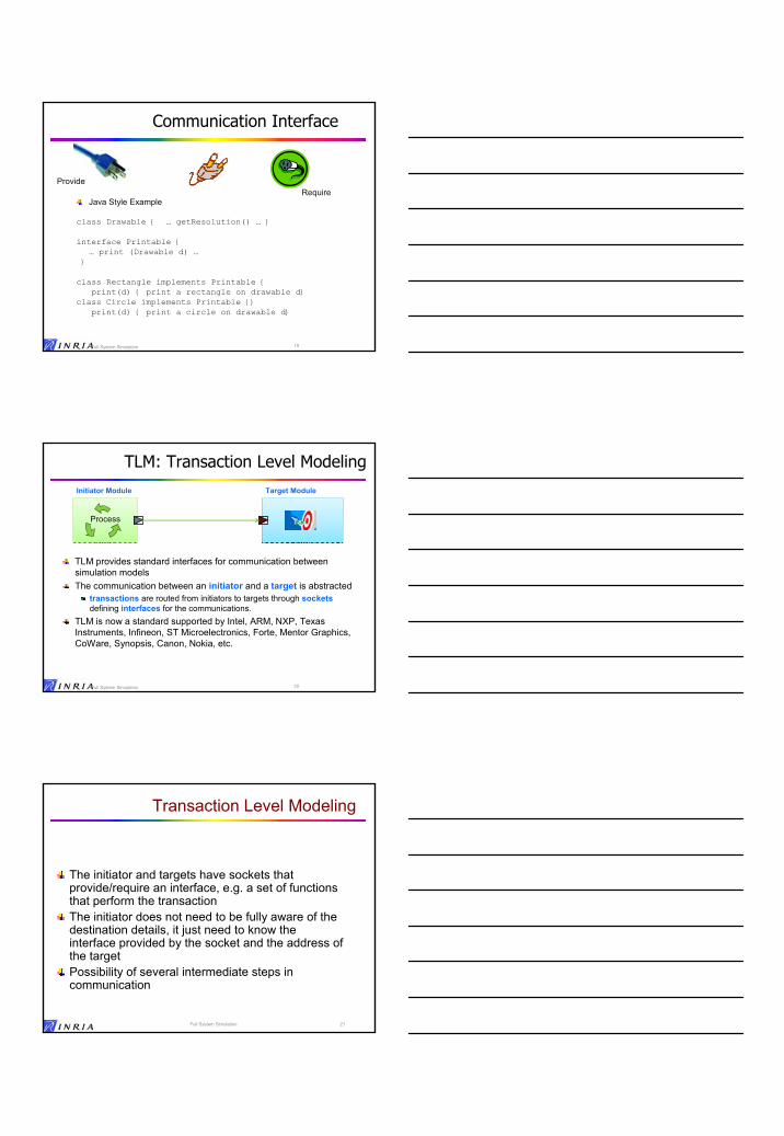
TLM: Transaction Level Modeling
TLM provides standard interfaces for communication between simulation modelsThe communication between an initiator and a target is abstracted
transactions are routed from initiators to targets through socketsdefining interfaces for the communications.
TLM is now a standard supported by Intel, ARM, NXP, Texas Instruments, Infineon, ST Microelectronics, Forte, Mentor Graphics, CoWare, Synopsis, Canon, Nokia, etc.
Initiator Module Target Module
Process
Transaction Level Modeling
The initiator and targets have sockets that provide/require an interface, e.g. a set of functions that perform the transactionThe initiator does not need to be fully aware of the destination details, it just need to know the interface provided by the socket and the address of the targetPossibility of several intermediate steps in communication
21Full System Simulation
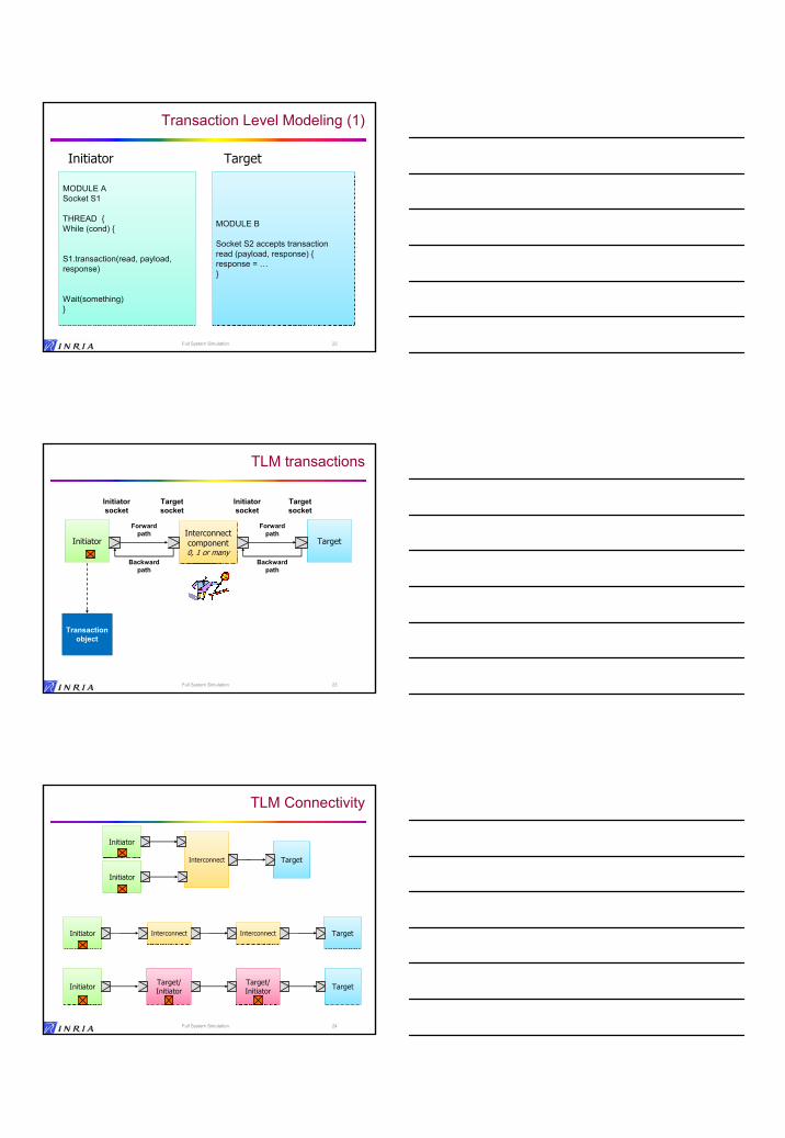
Transaction Level Modeling (1)
MODULE A Socket S1
THREAD {While (cond) {
S1.transaction(read, payload, response)
Wait(something)}
MODULE A Socket S1
THREAD {While (cond) {
S1.transaction(read, payload, response)
Wait(something)}
MODULE B
Socket S2 accepts transaction read (payload, response) { response = …}
MODULE B
Socket S2 accepts transaction read (payload, response) { response = …}
Initiator Target
22Full System Simulation
TLM transactions
Full System Simulation 23
InitiatorInitiatorInterconnect component0, 1 or many
Interconnect component0, 1 or many
TargetTarget
Initiator socket
Target socket
Initiator socket
Target socket
Forward path
Backward path
Forward path
Backward path
Transaction object
Transaction object
TLM Connectivity
Full System Simulation 24
Target/ InitiatorTarget/ Initiator
Target/ InitiatorTarget/ InitiatorInitiatorInitiator TargetTarget
InterconnectInterconnect TargetTargetInterconnectInterconnectInitiatorInitiator
TargetTargetInterconnectInterconnect
InitiatorInitiator
InitiatorInitiator

TLM Blocking vs Non-blocking Transport
Blocking transport interfaceIncludes timing annotationTypically used with loosely-timed coding styleForward path only
Non-blocking transport interfaceIncludes timing annotation and transaction phasesTypically used with approximately-timed coding styleCalled on forward and backward paths
Share the same transaction type for interoperability
Unified interface and sockets – can be mixed
25
TLM 2.0 Blocking Transport
26
template < typename TRANS = tlm_generic_payload >
class tlm_blocking_transport_if : public virtual sc_core::sc_interface {public:
virtual void b_transport ( TRANS& trans , sc_core::sc_time& t ) = 0;};
Timing annotationTransaction object
Transaction type
TLM 2.0 Blocking Transport
27
Initiator Target
b_transport(t, 0ns)Call
Simulation time = 100ns
Simulation time = 140ns wait(40ns)
Initiator is blocked until return from b_transport
Returnb_transport(t, 0ns)
b_transport(t, 0ns)Call
Returnb_transport(t, 0ns)

TLM 2.0 Non-blocking Transport
28
enum tlm_sync_enum { TLM_ACCEPTED, TLM_UPDATED, TLM_COMPLETED };
template < typename TRANS = tlm_generic_payload,typename PHASE = tlm_phase>
class tlm_fw_nonblocking_transport_if : public virtual sc_core::sc_interface {public:
virtual tlm_sync_enum nb_transport( TRANS& trans,PHASE& phase,sc_core::sc_time& t ) = 0;
};
Trans, phase and time arguments set by caller and modified by callee
TLM 2.0 Non Blocking Transport
29
Initiator TargetPhase
BEGIN_REQ
-, BEGIN_REQ, 0nsCall
Simulation time = 100ns
TLM_COMPLETED, END_RESP, 5ns Return
-, BEGIN_RESP, 0ns
BEGIN_RESP
Call
Simulation time = 150ns
TLM_UPDATED, END_REQ, 10nsReturn
END_REQ Simulation time = 110ns
Callee annotates delay to next transition, caller waits
END_RESP Simulation time = 155ns
Timing Annotation
30
InitiatorTarget
Phase
-, BEGIN_REQ, 10nsCall
TLM_ACCEPTED, -, - Return
Simulation time = 100ns
Simulation time = 110nsBEGIN_REQ
-, END_REQ, 10ns Call
Simulation time = 125ns
TLM_ACCEPTED, -, -Return
END_REQ Simulation time = 135ns
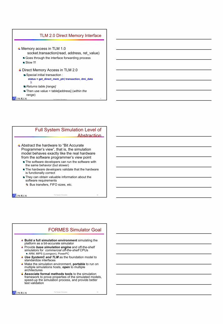
TLM 2.0 Direct Memory Interface
Memory access in TLM 1.0socket.transaction(read, address, ret_value)
Goes through the interface forwarding processSlow !!!
Direct Memory Access in TLM 2.0Special initial transaction :
status = get_direct_mem_ptr( transaction, dmi_data );
Returns table [range]Then use value = table[address] (within the range)
31Full System Simulation
Full System Simulation Level of Abstraction
Abstract the hardware to “Bit Accurate Programmer’s view”, that is, the simulation model behaves exactly like the real hardware from the software programmer’s view point
The software developers can run the software with the same behavior (but slower)The hardware developers validate that the hardware is functionally correctThey can obtain valuable information about the software requirements
Bus transfers, FIFO sizes, etc.
32Full System Simulation
Full System Simulation 33
FORMES Simulator Goal
Build a full simulation environment simulating the platform as a bit-accurate simulatorProvide base simulation engine and off-the-shelf simulators for commercial off-the-shelf CPUs
ARM, MIPS (Loongson), PowerPC Use SystemC and TLM as the foundation model to standardize interfacesMake the simulation environment, portable to run on multiple simulations hosts, open to multiple architectures Associate formal methods tools to the simulation framework to prove properties of the simulated models, speed-up the simulation process, and provide better test validation

Computer Architecture Reminder
Processors execute instructionsArithmetic / Logic instructions on integers or floating pointCondition and Branch instructionsMemory access instructionsPeripheral commands instructions (viewed as memory)
A processor may be interrupted by external devicesAn interrupt stops the current program and executes another program : the interrupt service routineAfter interrupt is handled it returns to normal executionOn virtually all processors, an instruction is atomic, it cannot be interrupted in the middle.
interrupts are checked before each instruction
Full System Simulation 34
Full System Simulation 35
Instruction Set Simulation (ISS)
Early simulation: Interpreted SimulationSimulate the instruction fetch/decode/execute of the target processorCode does essentially
do {instruction = Fetch (current_pc);Decode (instruction);Execute (instruction);
} until End Of Program
Inefficiency due to decode multiple times the same instructions : speed < 10 Mips
Simulated Memory Binary
instructionsData
FetchFetch DecodeDecode ExecuteExecute
How to do better ?
Translation:Translate in some way the executable code into another representation run on the simulation hostEliminate most of the decode time, speed up the execute timeCache the translated code for re-use
36Full System Simulation

Static Translation
Static translation compiles the target program into a host program
Fast but not flexibleDoes not handle all cases, for example dynamically loaded libraries, or self modifying codeBad throughput in development mode (cycle compile + simulation)
Full System Simulation 37
Target Executable Binary
Binary Translatiion
Host Executable
Using Binary Translation
Translation Analyzer and Generator
Host C Compiler
New C code
Using C Intermediate code
Host Executable
Dynamic (Cached) Translation
Translation:Eliminate most of the decode time, speed up the execute timeEntire compilation step included into simulation run-time.Cache the translated code for re-use
AdvantageHandles all cases, including self modifying code or code generating applicationsNo additional step required before running simulationNo problem to mix with other TLM modulesMuch faster simulation
InconvenientThe translation time is added to the simulation timeHowever possibilities to decrease translation time with some pre-compile steps…
Dynamic TranslationDynamic Translation Simulation time = translation time + execution time Simulation time = translation time + execution time
38Full System Simulation
CacheCache
Dynamic (Cached) Translation (2)
Translation can be done on segment or page basisSpeed increases significantly > 10 Mips
Simulated MemorySimulated Memory
Binary instructions
Binary instructions
Executable Intermediate
Representation
DataData
FetchFetch DecodeDecode
decoded?decoded?
ExecuteExecute
yesno
39Full System Simulation
TranslateTranslate
Full System Simulation 40
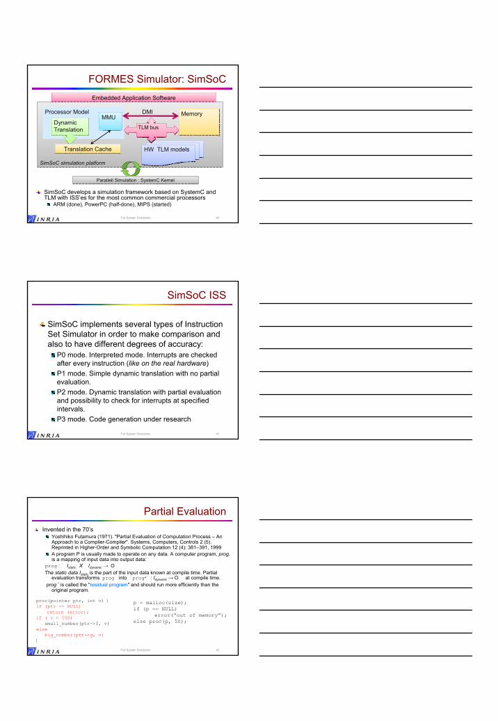
FORMES Simulator: SimSoC
SimSoC develops a simulation framework based on SystemC and TLM with ISS’es for the most common commercial processors
ARM (done), PowerPC (half-done), MIPS (started)
SimSoC simulation platformSimSoC simulation platform
HW TLM modelsHW TLM models
Embedded Application SoftwareEmbedded Application Software
TLM busTLM bus
Parallell Simulation : SystemC KernelParallell Simulation : SystemC Kernel
Processor Model
Dynamic TranslationDynamic Translation
MMUMMU MemoryMemoryDMI
Translation CacheTranslation Cache
SimSoC ISS
SimSoC implements several types of Instruction Set Simulator in order to make comparison and also to have different degrees of accuracy:
P0 mode. Interpreted mode. Interrupts are checked after every instruction (like on the real hardware)P1 mode. Simple dynamic translation with no partial evaluation. P2 mode. Dynamic translation with partial evaluation and possibility to check for interrupts at specified intervals.P3 mode. Code generation under research
41Full System Simulation
Partial EvaluationInvented in the 70’s
Yoshihiko Futamura (1971). "Partial Evaluation of Computation Process – An Approach to a Compiler-Compiler". Systems, Computers, Controls 2 (5). Reprinted in Higher-Order and Symbolic Computation 12 (4): 381–391, 1999A program P is usually made to operate on any data. A computer program, prog, is a mapping of input data into output data:
prog : Istatic X Idynamic → O The static data Istatic is the part of the input data known at compile time. Partial
evaluation transforms prog into prog* : Idynamic → O at compile time.prog * is called the "residual program" and should run more efficiently than the
original program.
Full System Simulation 42
proc(pointer ptr, int v) {if (ptr == NULL)
return (error);if ( v < 100)
small_number(ptr->f, v)else
big_number(ptr->g, v)}
p = malloc(size);if (p == NULL)
error(“out of memory”);else proc(p, 50);

Dynamic translation with partial evaluation
At instruction decoding time, you know which operation on which dataHence possible to use partial evaluation compilation techniques to translateUses more memory, but memory is cheap and caches are larger and larger
Full System Simulation 43
Partial Evaluation in Translation
Partial Evaluation Technique can be used in binary translationMany instructions to reach the internal switch case on example But this information is known at decoding time…
Possible to use partial evaluation
Can be specialized into multiple specialized functions with arguments evaluated at compile timeEach function uses many less instructions
significant performance enhancement
ExampleOperation(op, operand1, operand2)switch(op){
case ADD: switch(operand1){
case A:…case B: switch (operand2) {
case X: ..case Y:…
}}
break;case SUB:
substract codecase MUL:
multiplye code...}
Multiple “specialized” functionsADD_operandA_operandX() {}ADD_operandA_operandY() {}ADD_operandB_operandX() {}SUB_operandA_operandB() {}… etc …
Full System Simulation 44
SimSoC partial evaluation
Translate each machine instructions into a pseudo-instruction that contains a pointer to the partial evaluation residual function f, called the semantic function, with the dynamic input as argument.
Full System Simulation 45
Instruction 1Instruction 2Instruction 3….Instruction N
Instruction 1Instruction 2Instruction 3….Instruction N
f1(args1)f2(args2)f3(args3)….fN(argsN)
f1(args1)f2(args2)f3(args3)….fN(argsN)
Machine code
Pseudo Instructions
Generating Semantic Functions
The number of such semantics function is potentially very large (232 for 32 bits instructions) but finite, and in fact manageable corresponding to computer architectureExample ARM
15 condition modes, 2 post-operation mode, 11 operand modes, 3 addressing mode, 4 operations (and, or, eor, not)4*3*11*2*15 = 3960 functions for boolean instructions
Therefore semantic functions can be generated and compiled before simulation and loaded at run time. Full System Simulation 46
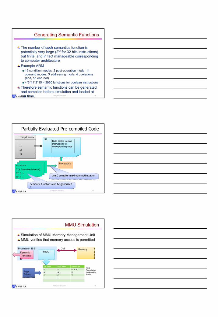
Full System Simulation 47
Partially Evaluated Pre-compiled Code
Processor.c
f1(){ Instruction behavior}
f2() {…}
f3() {…}
Processor.o
I1
I2
I3
I1
I2
I3
ISSISSBuild tables to map instructions to corresponding code
Target binary
Semantic functions can be generated !Semantic functions can be generated !
Use C compiler maximum optimization !Use C compiler maximum optimization !
MMU Simulation
Simulation of MMU Memory Management UnitMMU verifies that memory access is permitted
Full System Simulation 48
Processor ISSDynamic Translation
Dynamic Translation
MMUMMUMemoryMemoryDMI
Virt. Addr. Phys. Addr. Permission
a1 p1 R, W, X
a2 p2 R
a3 p3 W
… …
TLB Translation Look-aside Buffer
Page TablesPage Tables

Memory overwrite ?
Memory overwrite ?
Memory management
The program may be deleted or modified. The cache must remain coherent. Necessary to keep track of memory access and possibly invalidate cache.
Full System Simulation 4949Full System Simulation
no yes
CacheCacheSimulated MemorySimulated Memory
Binary instructions
Binary instructions
Executable Intermediate
Representation
DataData
FetchFetch DecodeDecode
decoded?decoded?
ExecuteExecute
yesno
TranslateTranslate
InvalidateInvalidate
MMU Simulation (2)
Because MMU associative hardware search is simulated with software table lookup, it is slow.Speed up solution:
Use a very large tableExample : for 32 bits virtual memory with pages of size 4K bytes (12 bits) use a 220 elements table to cache every page. Search done in one memory access.
Checking memory overwrite is slow if one test for every memory access instruction
Use host system memory protectionFull System Simulation 50
Simulation Speed Results
Interpreted Simple Dynamic
Translation
Dynamic Translation
with specialization
ARM32 no optimization
6.62 Mips 15.6 Mips 59.9 Mips
ARM32 max optimization
6.84 Mips 15.3 Mips 82.3 Mips
THUMB no optimization
5.01 Mips 17.3 Mips 65.4 Mips
THUMB max optimization
5.40 Mips 17.8 Mips 60.7 Mips
51Full System Simulation

Influence of Direct Memory Access
No dynamic translation Dynamic translation
no DMI with DMI no DMI with DMI
ARM32 no optimization
7.2 Mips 11.8 Mips 32 Mips 123 Mips
ARM32 max optimization
7.8 Mips 11.1 Mips 75 Mips 140 Mips
THUMB no optimization
5.9 Mips 10.8 Mips 61 Mips 123 Mips
THUMB max optimization
5.9 Mips 10 Mips 75 Mips 110 Mips
52Full System Simulation
FORMES Simulator status as of 2009/01
Simulation Framework developed for– ARM architecture (Arm Version 5) – PowerPC under development (2009) – MIPS targeted for 2010– Compliant with standard IEEE 1666 and TLM
Full System Simulation 53
60.7 Mips17.8 Mips5.40 MipsTHUMB –O3
65.4 Mips17.3 Mips5.01 MipsTHUMB –O0
82.3 Mips15.3 Mips6.84 Mips ARM32 –O3
59.9 Mips15.6 Mips6.62 Mips ARM32 –O0
Optimized Translation
Simple Translation
Interpreted
Over-specialization decreases performance…
Specialized Over-specialized
ARM32 no opt. 59.9 Mips 58.6 Mips
ARM32 max optimization 82.3 Mips 78.3 Mips
Reason: over-specialization creates tens of thousands of functions, each of them rarely used.
They do not all fit in the host cache….Cache thrashing on the host deteriorates performance.
Conclusion: specialize until the cache is full...
Full System Simulation 54
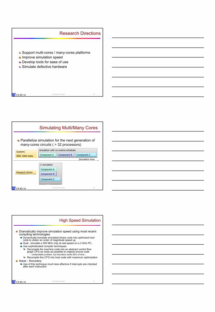
Research Directions
Support multi-cores / many-cores platformsImprove simulation speedDevelop tools for ease of useSimulate defective hardware
Full System Simulation 55
Simulating Multi/Many Cores
Parallelize simulation for the next generation of many-cores circuits ( > 32 processors)
Full System Simulation 56
// simulation// simulation
simulation with co-routine schedulersimulation with co-routine scheduler
Component AComponent A Component BComponent B Component CComponent CSystemC
IEEE 1666 today
SystemC
IEEE 1666 today
Research ActionResearch Action
Simulation time
Component AComponent A
Component BComponent B
Component CComponent C
High Speed Simulation
Dramatically improve simulation speed using most recent compiling technologies
Dynamically translate simulated binary code into optimized host code to obtain an order of magnitude speed upGoal : simulate a 300 MHz chip at real speed on a 3 GHz PC.Use sophisticated compiler techniques.
Decompile the machine code into an abstract control flow graph CFG as close as possible to original source code
– Undecidable problem, but heuristics works 80% of time…Recompile this CFG into host code with maximum optimization
Issue : AccuracyUse of this technique much less effective if interrupts are checked after each instruction
Full System Simulation 57

Code Generation
The machine code is first decompiled into a Control Flow Graphthen recompiled into host machine code and executed under control of execution engineTwo existing such simulators : Boston University, Edinburgh UniversityIntermediate solution : QEMU builds the CFG and generates a sequence of macro instructions
Full System Simulation 58
CacheCacheSimulated MemorySimulated Memory Binary
instructionsCFGData
FetchFetch Decode Decompile
Decode Decompile
decoded?decoded?
Execution engineyesno
invalidateOver Write ?
noyes
Native Host Code
Run Native
compile
Full System Simulation 59
Research : Parallelize Translation
On multi-processors simulation hosts, it is possible to translate not just-in-time (when necessary to execute an instruction) but in parallel ahead-of-timeThe translation time does not hurt performance when the process is parallel to the execution process
Since it does not hurt performance, the compilation can be made more complex with more optimizations
ResearchSimulation time // Simulation time //
translation time translation time
+ execution time + execution time Today simulation time == translation time
translation time
execution time execution time
Ease of Use
Currently, simulators are build by manually assembling components using SystemC interfaces:
Time consuming, errors, little flexibility…Research:
Generate the simulator(s) from a library of existing industry components models using a higher level tool, generating SystemC code, with some kind of type checking control to detect errors
Full System Simulation 60

Conclusion
Full System Simulation has achieved significant results but we are still far from simulating many-cores circuits at real speed. We have work to do …
Full System Simulation61
谢谢
FORMES: A joint project between INRIA and Tsinghua and Beihang University