Embedded Systems - HS 19 · Institut für Technische Informatik und Kommunikationsnetze...
16
Institut für T echnische Informatik und Kommunikationsnetze Dr. Jan Beutel Embedded Systems - HS 19 Lab 0 Date : 23.9.2019 Prelab – Filling the gaps Goals of this Lab You are expected to already be familiar with C programming. If not, your are strongly invited to carefully read through the C Programming Crash Course part of the Embedded System Companion. 1 You will need basic C knowledge to successfully go through the labs. The goal of this Prelab is to cover the additional background necessary for the forthcoming Embedded Systems labs. The first part of the lab is a crash course on the following topics: • Numeral systems • Ordering and Endianness • Generics types • C operators • Overflows The second part of the lab is a set of short programming tasks designed to highlight the specific problems and pitfalls one may fall into when working with embedded systems. Once you have completed these tasks, you will be good to go for the rest of the labs! 1 C programming for embedded systems Warning 1: Basic C programming You should already be familiar with C programming. If not, your are strongly invited to have a look at the C Programming Crash Course. a You will need basic C knowledge to successfully go through the labs. a https://lectures.tik.ee.ethz.ch/es/labs/companion.pdf Task 1: Warm-up In programming (like for many things), it is important to be precise with the terms one uses, otherwise it is difficult to understand one another. As a warm-up, let’s have a look at the simplest C program one can write: HelloWorld.c 1 https://lectures.tik.ee.ethz.ch/es/labs/companion.pdf 1
Transcript of Embedded Systems - HS 19 · Institut für Technische Informatik und Kommunikationsnetze...

Institut fürTechnische Informatik undKommunikationsnetze
Dr. Jan Beutel
Embedded Systems - HS 19
Lab 0Date : 23.9.2019
Prelab – Filling the gaps
Goals of this Lab
You are expected to already be familiar with C programming. If not, your are strongly invited to carefullyread through the C Programming Crash Course part of the Embedded System Companion. 1 You willneed basic C knowledge to successfully go through the labs.The goal of this Prelab is to cover the additional background necessary for the forthcoming EmbeddedSystems labs. The first part of the lab is a crash course on the following topics:
• Numeral systems• Ordering and Endianness• Generics types
• C operators• Overflows
The second part of the lab is a set of short programming tasks designed to highlight the specific problemsand pitfalls one may fall into when working with embedded systems.Once you have completed these tasks, you will be good to go for the rest of the labs!
1 C programming for embedded systems
Warning 1: Basic C programmingYou should already be familiar with C programming. If not, your are strongly invited to have a lookat the C Programming Crash Course. a You will need basic C knowledge to successfully go throughthe labs.
ahttps://lectures.tik.ee.ethz.ch/es/labs/companion.pdf
Task 1: Warm-upIn programming (like for many things), it is important to be precise with the terms one uses, otherwiseit is difficult to understand one another.As a warm-up, let’s have a look at the simplest C program one can write: HelloWorld.c
1https://lectures.tik.ee.ethz.ch/es/labs/companion.pdf
1

1 # include <stdio .h>2 # include <stdlib .h>34 int main ()5 {6 printf (" Hello world !\n");7 return 0;8 }
Clicker Questions – #1
Which lines in this program are ...
(a) processor instructions?
(b) preprocessor directives?
(c) function prototypes?
(d) part of a function definition?
Many embedded system programmers use C. Once again, you should be generally familiar with thelanguage (if not, go read up the C Programming Crash Course! 2). Moreover, embedded system pro-gramming also requires some “low-level” features of C which you may not know.The rest of this section gives a quick overview of what you should know. Some clicker questions at theend will verify that you understand the main concepts.
1.1 Numeral systems
A number can be represented in different numeral systems, corresponding to different bases (i.e., thenumber of different symbols usable). In embedded system programming, mainly three systems are used:binary, decimal, and hexadecimal.
Table 1: Main numeral systems for embedded programming
Numeral system Base Symbols Interpretation of “11”
Binary 2 0 1 3Decimal 10 0 1 2 3 4 5 6 7 8 9 11Hexadecimal 16 0 1 2 3 4 5 6 7 8 9 a b c d e f 17
Recap 1: Bits and SymbolsThe binary symbols (0 and 1) are also called bits.
All numeral systems work similarly. Each symbol correspond to a power of the base. The symbol’s valueis a multiplication factor.For example with an arbitrary base b:
153b = 3 ∗ b0 + 5 ∗ b1 + 1 ∗ b2
2https://lectures.tik.ee.ethz.ch/es/labs/companion.pdf
2

In the decimal format, when reading 153, you interpret it as 3 ∗ 1 + 5 ∗ 10 + 1 ∗ 100. This is base 10.It works exactly the same for the hexadecimal and binary systems.
15316 = 1 ∗ 162 + 5 ∗ 161 + 3 ∗ 160
= 1 ∗ 256 + 5 ∗ 16 + 3 ∗ 1= 339
10012 = 1 ∗ 23 + 0 ∗ 22 + 0 ∗ 21 + 1 ∗ 20
= 1 ∗ 8 + 0 + 0 + 1= 9
In C, one can use any of those systems to work on numbers, as long as you inform the compiler with a“header” before the number: “0x” for hexadecimal, “0b” for binary. Without precision, all numbers areinterpreted as decimal.
1 /* Equivalent definitions of the same number */2 int myNumber = 339; // myNumber in decimal3 int myNumber = 0x153; // myNumber in hexedecimal4 int myNumber = 0 b101010011 ; // myNumber in binary
Why can’t we just use decimal? Computers only understand 0 and 1. Therefore, binary is the“natural” numeral system of a computer. Moreover, embedded systems programmers often have to workat the “bit-level” (e.g., when dealing with registers). In practice, you may have an 8-bit register connectedto GPIO pins. To set the third pin to high, one must set the register equal to an integer value such that,in binary, the third bit equals 1. We will practice this in Task 5.
Relation between binary and hexadecimal The hexadeximal system is extremely common in pro-gramming, for a simple reason: it is compact, converts easily to binary and is easier to read.The idea is simple. One hexadecimal symbol can take 16 different values (from 0 to 15), which is thesame as a 4-symbol binary number. For example
in decimal 4 13 6 150b 0100 1101 0110 11110x 4 d 6 f
⇒ 0b 0100 1101 0110 1111 = 0x4d6f
Thus, two hexadecimal symbols “encode” one Byte, i.e., 8 bits.
1.2 Ordering consideration
Most and least significant bits The most significant bit (MSB) is the bit of a binary number havingthe greatest value (which depends on the number of bits: (2N−1 for a N -bit number), i.e., the left-mostone.Conversely, the least significant bit (LSB) is the bit of a binary number having the smallest value, whichis always 1, i.e., the right-most one.
1 // 0b _ _ _ _ _ _ _ _2 // ^ ^3 // MSB LSB
Endianness The endianness refers to the sequential order in which Bytes are arranged into largernumerical values when stored in memory or when transmitted (over a bus, the radio, etc.).In big-endian format, the most significant Byte (i.e., the Byte containing the MSB) is stored/sent first.In little-endian format, the least significant Byte (i.e., the Byte containing the LSB) is stored/sent first.
3

1.3 Generic integer types
The C programming language provides four different data types, e.g., char (for characters), int (forintegers), float and double (for fractionals). These types can be either signed or unsigned.A variable can contain any number within a range that depends on the number of bits reserved in memoryfor this variable. For example, with 8 bits, one can store any number within [0, 255] for an unsigned integeror [−128, +127] for a signed one.In C, the number of bits used to encode integer types is not fixed. This varies between implemen-tations (e.g., depending on the platform or the CPU). The problem is that when you declare an intvariable in C, it is not clear how many bits are then reserved in memory. Thus, if you run the sameprogram on different platforms, the size of an int can change, which may lead e.g., to overflows.To avoid this problem, embedded programmers use generic integer types (also called fixed-width integers).The idea is simple: the type uintN_t is used to store an unsigned integer number encoded with N bits.N can generally be 8, 16, 32, or 64. The following table summarizes these types and their value range.
Table 2: Ranges of 8, 16, and 32-bits fixed-width integer types
Unsigned types Signed typesType Min value Max value Type Min value Max value
uint8_t 0 255 int8_t -128 127uint16_t 0 65535 int16_t -32768 32767uint32_t 0 4294967295 int32_t -2147483648 2147483647
Recap 2: Standart Integer libraryThese generic types are defined in the stdint.h library. Don’t forget to include it in your project, orthe compiler will complain!
1.4 C Operators
The C language provides a wide range of operators that you should know about.
Arithmetic operators Addition (+) subtraction (-) multiplication (*) division (/) and modulo (%).
Recap 3: Integer division and moduloIn “normal” calculation, 9/4 = 2.25. However, in C, the result is 2. This is because the result of anoperation on integers in also an integer. The compiler neglects the term after the decimal point.The modulo operator (%) computes the remainder. If a = 9 is divided by b = 4, the remainder is 1(i.e., a%b = 1). The modulo operator can only be used with integers.
Increment and Decrement A short-hand notation; e.g., “a = a+1” and “a + +” are equivalent.
Assignment operators Another short-hand notation (see Table 3).
Tests Equal (==) Greater (>) Greater or equal (>=)Not equal (!=) Smaller (<) Smaller or equal (<=)
4
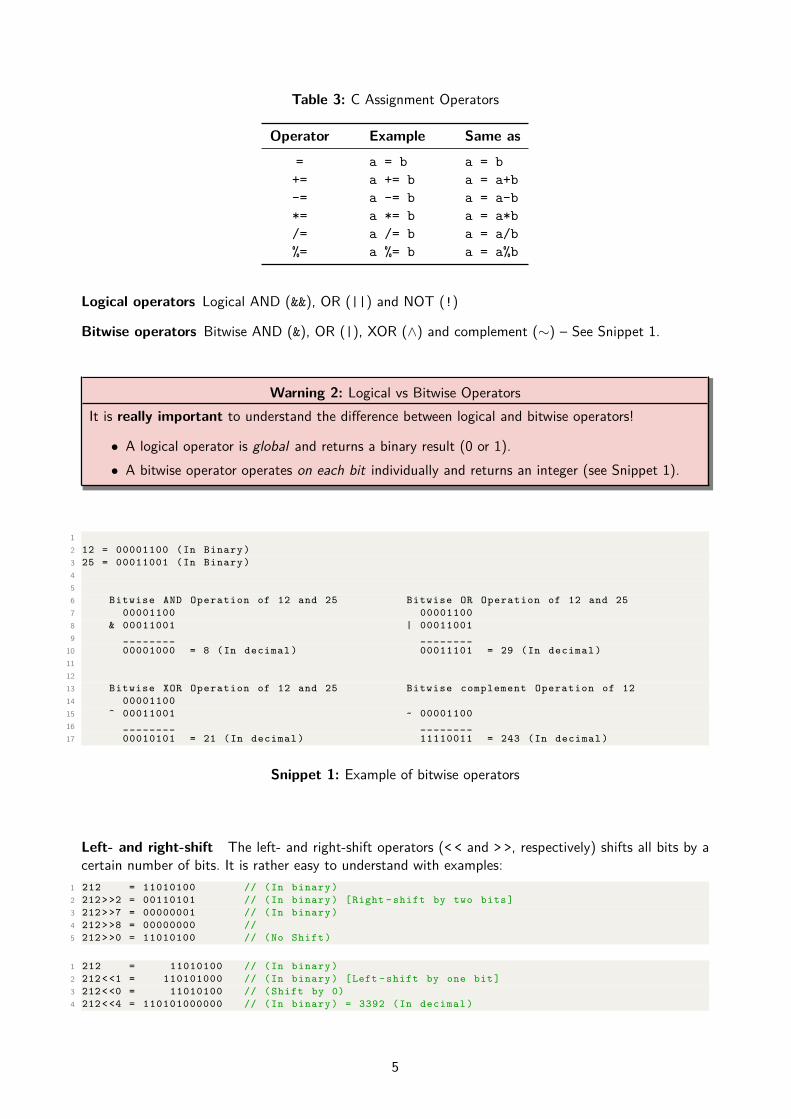
Table 3: C Assignment Operators
Operator Example Same as
= a = b a = b+= a += b a = a+b-= a -= b a = a-b*= a *= b a = a*b/= a /= b a = a/b%= a %= b a = a%b
Logical operators Logical AND (&&), OR (||) and NOT (!)
Bitwise operators Bitwise AND (&), OR (|), XOR (∧) and complement (∼) – See Snippet 1.
Warning 2: Logical vs Bitwise OperatorsIt is really important to understand the difference between logical and bitwise operators!
• A logical operator is global and returns a binary result (0 or 1).• A bitwise operator operates on each bit individually and returns an integer (see Snippet 1).
12 12 = 00001100 (In Binary )3 25 = 00011001 (In Binary )456 Bitwise AND Operation of 12 and 25 Bitwise OR Operation of 12 and 257 00001100 000011008 & 00011001 | 000110019 ________ ________
10 00001000 = 8 (In decimal ) 00011101 = 29 (In decimal )111213 Bitwise XOR Operation of 12 and 25 Bitwise complement Operation of 1214 0000110015 ^ 00011001 ~ 0000110016 ________ ________17 00010101 = 21 (In decimal ) 11110011 = 243 (In decimal )
Snippet 1: Example of bitwise operators
Left- and right-shift The left- and right-shift operators (< < and > >, respectively) shifts all bits by acertain number of bits. It is rather easy to understand with examples:
1 212 = 11010100 // (In binary )2 212 > >2 = 00110101 // (In binary ) [Right - shift by two bits]3 212 > >7 = 00000001 // (In binary )4 212 > >8 = 00000000 //5 212 > >0 = 11010100 // (No Shift )
1 212 = 11010100 // (In binary )2 212 < <1 = 110101000 // (In binary ) [Left - shift by one bit]3 212 < <0 = 11010100 // ( Shift by 0)4 212 < <4 = 110101000000 // (In binary ) = 3392 (In decimal )
5

Note that, as shown in the last example, a left-shift can lead to “increase” the number of bits. However,keep in mind that this may happen only if there is “room left” in memory. Consider the following example:
1 uint8_t b = 255 ; // b = 11111111 (In binary )2 printf ("%u\n", b); // Prints : ‘‘255’’3 printf ("%u\n", b << 4); // Creates a temporary variable of 12 bits and prints it.4 // -> Prints : ‘‘4080’’56 b = b << 4 ; // Left - shifts and assigns back to b, which is 8-bit long.7 // -> b = 11110000 (In binary )8 printf ("%u\n", b); // Prints : ‘‘240’’
In line 6, the bits of b are left-shifted by 4 bits then assigned back to b, which is only 8-bit long. Thus,only the least significant 8 bits are stored in b and eventually printed in line 8.Shifts are extremely useful when one needs to work on specific bits, e.g., on registers, like in the followingexample.
1 REG = ( REG | (0 x01 << 2 )); // Sets the third bit of REG to 12 // without modifying any of the other bits
sizeof The sizeof operator returns the size of data (constant, variables, array, structure etc) in Bytes,as illustrate below.
1 struct student { // the structure name2 char name [80]; // first variable : an array of characters3 float size; // second variable : an decimal value4 int8_t age; // third variable : an integer5 };6 printf ("%d bytes ",sizeof ( struct student )); // Prints ‘‘82 bytes ’’
1.5 Variable overflow
Standard computers possess plenty of memory and processing power. Contrary, embedded systems aregenerally more resource constrained. It is therefore important to carefully choose integer types: storing acounter value expected to range between 0 and 10 in a uint64_t wastes a lot of memory!However, one must be carefull with overflows. A variable is said to overflow when it is assigned a valuewhich is outside the range that its type can normally contain. For example, a uint8_t can contain anynumber between 0 and 255. What happens if you assign e.g., 300 to such variable?
1 uint8_t a = 300; // assign 300 , even though the max value is 2552 printf ("%u", a); // Prints : ‘‘44’’
The problem is similar to the previous example with the left-shift: 300 requires 9 bits to be written inbinary. As the variable “a” is only 8-bit long, only the least significant (lower) 8 bits of 300 will beassigned to “a”, that is 00101100, which is 44 in decimal (You may also note that 44 = 300%256).Also be careful with subtractions of unsigned integers. Negative values are not defined! If you assign anegative value, the variable “wraps-around”, like in the following example.
1 uint8_t a = 0;2 a--;3 printf ("%u", a); // Prints : ‘‘255’’
6

Clicker Questions – #2
1. How is 0b0110 written in decimal?(a) 10(b) 0d0110
(c) 6(d) 42
2. How is 0b1110 written in hexadecimal?(a) 0x0E(b) 0x10
(c) 0xE(d) 0xF
3. How is 0xC written in binary?
(a) 0b1010(b) 0b0110
(c) 0b1100(d) 0b1110
4. How is 0xD3 written in binary?
(a) 0b1001 0011(b) 0b1101 0101
(c) 0b1100 0011(d) 0b1101 0011
5. What is the output of the printf instruction (line 8)?1 int main ()2 {3 uint8_t counter = 10;4 /*5 * Some code ...6 */7 reset ( counter );8 printf ("%u", counter );9
10 return 0;11 }12 void reset ( uint8_t x)13 {14 x = 0;15 }
(a) 0(b) 10
(c) 42(d) Impossible to know
6. What is the value of sizeof(int)?(a) 1(b) 2
(c) 16(d) Impossible to know
7. What is the value of sizeof(uint16_t)?
(a) 1(b) 2
(c) 16(d) Impossible to know
8. Let us assume the following definition1 uint16_t REG = 0xC1;
Which instructions lead to REG = 0b 1100 0011?(a) REG = ( REG | (0x01 > > 1))
(b) REG = ( REG || (0x01 > > 1))
(c) REG = ( REG | (0x01 < < 1))
(d) REG = ( REG || (0x01 < < 1))
7

9. Consider the following program and select all correct statements among the following.1 int main ()2 {3 uint8_t *ptr;4 uint8_t x = 0;5 ptr = &x;67 printf ("%u", *ptr);8 printf ("%u", &ptr);9 printf ("%u", &x);
1011 return 0;12 }
(a) Line 7 prints the address of x.(b) Line 7 prints the value of x.(c) Line 7 prints the address of ptr.(d) Line 7 prints the value of prt.(e) Line 8 prints the address of x.(f) Line 8 prints the value of x.
(g) Line 8 prints the address of ptr.(h) Line 8 prints the value of prt.(i) Line 9 prints the address of x.(j) Line 9 prints the value of x.(k) Line 9 prints the address of ptr.(l) Line 9 prints the value of prt.
8

2 Putting it to practice
It is time to put all these notions into practice! We will start using the MSP-EXP432P401R LaunchPadDevelopment Kit which has been provided to you. For now, you just need to know how to plug it in (seeFigure 1). More details about what it is/what it contains will be given in Lab 1.
Figure 1: A basic overview of the MSP-EXP432P401R LaunchPad Development Board (left) and con-nected to a laptop via USB (right).
We use Code Composer Studio (CCS) as development environment. CCS can be started by typingccstudio into a terminal. It allows easy integration of the LaunchPad, software, etc. Furthermore, itmakes compiling of a whole project a one-click task by generating and executing the necessary makefiles,and features extensive debugging options (more details in the following labs).
Task 2: Your first embedded system program
Task 2.1: Flash your very first program!
• Download lab0.zip from the course website. 3
• Open CCS and import lab0.zip to your workspace (see Figure 4 in the Appendix).• Connect the LaunchPad to the Computer.• Build and flash the application ( , see Figure 5,6,7)
• Start the execution ( ) and observe the functionality of the program. What is the purpose of theapplication?
Warning 3: Creating a delay within a programIn this lab, we use an empty for-loop for delaying the program. Note that this is not a good solutionin practice. Timers should be used instead. We use this simple solution for now as timers will becovered later in Lab 2.
3https://lectures.tik.ee.ethz.ch/es/labs/lab0.zip
9

Task 2.2: Track the number of toggling operationsWe provide you with a custom uart_println function which prints to a terminal on your PC. Usethis function exactly as you would use the standard printf function in C. In Task 2.2 we will modifytask_2.c to keep track of the program execution by using a counter.
Recap 4: Print statement on embedded systemsWhy do we need a custom function to print? Monitoring the execution of an embedded program isa complex task (covered in more details in Lab 2). The standard printf function does not help inour setting. Think about it this way: The embedded platform is lying on your desk, and executes aprintf instruction; where would the string actually be printed?
• Stop the execution of the program ( ). Open task_2.c.• Declare a counter (uint32_t type) and initialize it to 0.• Within the while loop, after toggling
– Print out the counter value using the uart_println function.– Increment the counter.
• Build and debug your program. Open a terminal in CCS to see your prints (see Figure 9, 10and 11) then start the program execution. Observe the print statements in the terminal. It shouldlook similar to Figure 2.
Figure 2: Expected output of Task 2.2.
Task 3: Adaptive toggling delayWe now modify the value of the delay between successive togglings, until 25 toggling operations havebeen executed. The program then prints a “task completed” message.
• In main.c, comment out task_2 and uncomment task_3. Open task_3 and observe the codeprovided.
• Build, flash and execute the application.• Observe that the program never executes the “task completed” print statement. What is theproblem?
• Correct the code to obtain the desired behavior. It should look similar to Figure 3.• What is the effect of defining the delay variable as static? What would happen if we don’t?
10

Figure 3: Expected output of Task 3.
Task 4: Use your own functionIn Task 4, we encapsulate the increment and print of the counter value in a function calledprint_and_increment. Like in Task 3, the program must eventually exit the while loop and printthe “task completed” message.
• In main.c, comment out task_3 and uncomment task_4. Open task_4 and observe the codeprovided.
• The prototype of the print_and_increment function is given (see line 40). Complete the definitionof the function (starts at line 77) to implement the increment and print of the input argument(called value).
• Call your function in the while-loop at the placeholder. Rebuild, run, and observe the “task com-pleted” print statement. The output must be similar as for Task 3 (see Figure 3).
• In line 40, replace your function prototype by the following
1 void print_and_increment ( uint32_t * value );
Rewrite your function implementation and the call in the while-loop such that the program behaviorremains the same.
• What is the difference between the two function techniques? How are they called?
Task 5: Taking control of the LEDsIn Task 5 the LEDs which are toggling will be changed. We will do this by using an 8-bit unsigned integercalled activeLED. The MSP432 Lauchpad has 2 LEDs. One red LED (which we have been using so far)and one RGB LED. An RGB LED has three inputs which can be activated separately to get red, green,blue or any mix of these three colours.Setting bits of activeLED high and low controls which of the red LED and the RGB LED inputs toggles.The mapping to the bits of activeLED is described below.
1 /*2 * Define activeLED3 *4 * activeLED : (MSB) _____ _____ _____ _____ ________ _________ _______ _______ (LSB)5 * ** unused bits ** RGB_BLUE RGB_GREEN RGB_RED LED_RED6 *7 * Set the bits in activeLED to toggle the corresponding LEDs8 */9 // ----------------led1 ----------------
11

Task 5.1: Static setup of the toggling LEDs
• In main.c, comment out task_4 and uncomment task_5. Open task_5 and observe the codeprovided.
• Build, flash and execute the application. What happens?• Modify the value of activeLED to toggle both the red LED and the red RGB LED simultaneously.
Try to do this using four different ways:- Using a decimal number, e.g., activeLED = 65;- Using a hexadecimal number, e.g., activeLED = 0x0001;- Using a binary number, e.g., activeLED = 0b01101010;- Using predified macros, e.g., activeLED = LED_RED; (Hint: use bitwise operators)
Warning 4Of course, these are only examples. They do not produce the expected output. . .
• Modify the value of activeLED to toggle all the LEDs at once (the RGB LED should appearwhite).
• What LEDs will toggle if you set activeLED to 137? To 257? Try to predict then verify.
Task 5.2: Dynamic LED togglingIn this final task, the goal is to dynamically change the toggling LEDs depending on the value of thecounter according to the specification in Table 4. For example, if counter = 10, 10%3=1 thus theLED_RED and RGB_GREEN should toggle.
Table 4: Specification of the expected toggling pattern of the LEDs.
(counter % 3) = 0 1 2
LED_RED 1 1 1RGB_RED 1 0 0RGB_GREEN 0 1 0RGB_BLUE 0 0 1
Modify the code in task_5.c (where indicated by the placeholders) to execute the desired togglingpattern. Try doing this in two different ways:
• Using conditions (e.g., if statements).• Without conditions (e.g., using shift operators).
Congrat’s! If you managed all these tasks, you should now be 100% ready for the upcoming labs :-)
12

Appendix
Figure 4: How to import a CCS project into your workspace in the CCS using the Import Wizard(File→Import). If the source code should be copied to the workspace, the corresponding check mark hasto be set.
Figure 5: The standard view of the CCS. The button to build and start debugging a project is markedwith a blue circle.
13

Figure 6: The debug view of the CCS.
Figure 7: Control buttons for debugging in the CCS Debug View. From left to right: Start/ContinueExecution, Pause Execution, Terminate Execution, Step In, Step Over, Step Out.
14

Figure 8: The context menu in CCS allows easycode browsing with searches (Declarations, Ref-erences, Search Text) or other commands (i.e.Open Declaration). It opens by right-clickinga function or a variable. Alternatively, one canalso use the sequence Ctrl+Left Click.
Figure 9: To open the terminal view, go toView→Terminal.
15

Figure 10: The terminal view opens in the lower right corner where a new terminal view can be opened.
Figure 11: The menu opened after pressing the new terminal button allows the configuration of theserial connection.
16