Embedded System Design || Introduction
34
Chapter 1 INTRODUCTION In this chapter we will look at the emergence of system design theory, prac- tice and tools. We will first look into the needs of system-level design and the driving force behind its emergence: increase in design complexity and widen- ing of productivity gap. In order to find an answer to these challenges and find a systematic approach for system design, we must first define design-abstraction levels; this will allow us to talk about design-flow needs on processor and sys- tems levels of abstraction. An efficient design-flow will employ clear and clean semantics in its languages and modeling, which is also, required by synthesis and verification tools. We will then analyze the system-level design flow and define necessary models, define each model separately and its use in the sys- tem design flow. We will also discuss the components and tools necessary for system design. We will finish with prediction on future directions in system design and the prospects for system design practice and tools. 1.1 SYSTEM-DESIGN CHALLENGES Driven by ever-increasing market demands for new applications and by tech- nological advances that allow designers to put complete many-processor sys- tems on a single chip (MPSoCs), system complexities are growing at an almost exponential rate. Together with the challenges inherent in the embedded-system design process with its very tight constraints and market pressures, not the least of which is reliability, we are finding that traditional design methods, in which systems are designed directly at the low hardware or software levels, are fast becoming infeasible. This leads us to the well-known productivity gap gener- ated by the disparity between the rapid paces at which design complexity has increased in comparison to that of design productivity [99]. © Springer Science + Business Media, LLC 2009 1 D.D. Gajski et al., Embedded System Design: Modeling, Synthesis and Verification, DOI: 10.1007/978-1-4419-0504-8_1,
Transcript of Embedded System Design || Introduction

Chapter 1
INTRODUCTION
In this chapter we will look at the emergence of system design theory, prac-tice and tools. We will first look into the needs of system-level design and thedriving force behind its emergence: increase in design complexity and widen-ing of productivity gap. In order to find an answer to these challenges and find asystematic approach for system design, we must first define design-abstractionlevels; this will allow us to talk about design-flow needs on processor and sys-tems levels of abstraction. An efficient design-flow will employ clear and cleansemantics in its languages and modeling, which is also, required by synthesisand verification tools. We will then analyze the system-level design flow anddefine necessary models, define each model separately and its use in the sys-tem design flow. We will also discuss the components and tools necessary forsystem design. We will finish with prediction on future directions in systemdesign and the prospects for system design practice and tools.
1.1 SYSTEM-DESIGN CHALLENGESDriven by ever-increasing market demands for new applications and by tech-
nological advances that allow designers to put complete many-processor sys-tems on a single chip (MPSoCs), system complexities are growing at an almostexponential rate. Together with the challenges inherent in the embedded-systemdesign process with its very tight constraints and market pressures, not the leastof which is reliability, we are finding that traditional design methods, in whichsystems are designed directly at the low hardware or software levels, are fastbecoming infeasible. This leads us to the well-known productivity gap gener-ated by the disparity between the rapid paces at which design complexity hasincreased in comparison to that of design productivity [99].
© Springer Science + Business Media, LLC 2009
1D.D. Gajski et al., Embedded System Design: Modeling, Synthesis and Verification,DOI: 10.1007/978-1-4419-0504-8_1,

2 Introduction
One of the commonly-accepted solutions for closing the productivity gap asproposed by all major semiconductor roadmaps is to raise the level of abstrac-tion in the design process. In order to achieve the acceptable productivity gainsand to bridge the semantic gap between higher abstraction levels and low-levelimplementations, the goal now is to automate the system-design process asmuch as possible. We must apply design-automation techniques for modeling,simulation, synthesis, and verification to the system-design process. However,automation is not easy if a system-abstraction level is not well-defined, if com-ponents on any particular abstraction level are not well-known, if system-designlanguages do not have clear semantics, or if the design rules and modeling stylesare not clear and simple. In the following chapters, we will show how to answerfor those challenges through sound system-design theories, practices, and tools.
On the modeling and simulation side, several approaches exist for the vir-tual prototyping of complete systems. These approaches are typically basedon some variant of C-based description, such as C-based System-Level De-sign Languages (SLDLs) like SystemC [150] or SpecC [171]. These virtualprototypes can be assembled at various levels of detail and abstraction.
The most common approach in the system design of a many-processorplatform is to perform co-simulation of software (SW) and hardware (HW)components. Both standard and application-specific processors are simulatedon nstruction-set level with an Instruction Set Simulator (ISS). The customHW components or Intellectual Property (IP) components are modeled with atimed functional model and integrated together with the processor models intoa Transaction-Level Model (TLM) representing the platform communicationbetween components.
In algorithmic-level approaches in designing MPSoCs, we use domain-specific application modeling, which is based on more formalized models ofcomputation, such as process networks or process state machines. These mod-eling approaches are often supported by graphical capture of models in termsof block diagrams, which hide the details of any underlying internal language.On the other hand, the code can be generated in a specific target language suchas C by model-based-design tools from such graphical input.
Such simulation-centric approaches enable the horizontal integration of var-ious components in different application domains. However, approaches forthe vertical integration for system synthesis and verification across componentor domain boundaries are limited. At best, there are some solutions for the C-based synthesis of single custom hardware units. But no commercial solutionsfor synthesis and verification at the system level, across hardware and softwareboundaries, currently exist.
In order to understand system-level possibilities more fully, however, wemust step back and explain the different abstraction levels involved in systemdesign.

Abstraction Levels 3
Behavior(F u n c t i o n )
S t ru c t u re(N e t l i s t )
P hy s ic al(L a y o u t )
LogicC ir cu it
P r oce s s orS y s t e m
F( . . . )
F( . . . )
F( . . . )
F( . . . )
FIGURE 1.1 Y-Chart
1.2 ABSTRACTION LEVELSThe growing capabilities of silicon technology over the previous decades has
forced design methodologies and tools to move to higher levels of abstraction.In order to explain the relationship between different design methodologies ondifferent abstraction levels, we will use the Y-Chart, which was developed in1983 in order to explain differences between different design tools and differentdesign methodologies in which these tools were used [60].
1.2.1 Y-CHARTThe Y-Chart makes the assumption that each design, no matter how complex,
can be modeled in three basic ways, which emphasize different properties ofthe same design. As shown in Figure 1.1, the Y-Chart has three axes repre-senting three aspects of every design: behavior (sometimes called functionalityor specification), design structure (also called netlist or a block diagram), andphysical design (usually called layout or board design). Behavior represents adesign as a black box and describes its outputs in terms of its inputs over time.The black-box behavior does not indicate in any way how to build the blackbox or what its structure is. That is given on the structure axis, where the blackbox is represented as a set of components and connections. Naturally, the be-havior of the black box can be derived from its component behaviors and theirconnectivity. However, such a derived behavior may be difficult to understandsince it is obscured by the details of each component and connection. Physical

4 Introduction
design adds dimensionality to the structure. It specifies the size (height andwidth) of each component, the position of each component, as well as each portand connection on the silicon chip, printed circuit board, or any other container.
The Y-Chart can also represent design on different abstraction levels, whichare identified by concentric circles around the origin. Typically, four levels areused: circuit, logic, processor, and system levels. The name of each abstractionlevel is derived from the types of the components generated on that abstractionlevel. Thus the components generated on the circuit level are standard cellswhich consist of N-type or P-type transistors, while on the logic level we uselogic gates and flip-flops to generate register-transfer components. These arerepresented by storage components such as registers and register files and byfunctional units such as ALUs and multipliers. On the processor level, we gen-erate standard and custom processors, or special-hardware components suchas memory controllers, arbiters, bridges, routers, and various interface compo-nents. On the system level, we design standard or embedded systems consistingof processors, memories, buses, and other processor components.
On each abstraction level, we also need a database of components to be used inbuilding the structure for a given behavior. This process of converting the givenbehavior into a structure on each abstraction level is called synthesis. Once astructure is defined and verified, we can proceed to the next lower abstractionlevel by further synthesizing each of the components in the structure. On theother hand, if each component in the database is given with its structure andphysical dimensions, we can proceed with physical design, which consists offloorplanning, placement, and routing on the chip or PC board. Thus eachcomponent in the database may have up to three different models representingthree different axes in the Y-Chart: behavior or function; structure, whichcontains the components from the lower level of abstraction; and the physicallayout of its structure.
Fortunately, all three models for each component are not typically neededmost of the time. Most of the methodologies presently in use perform design orsynthesis on the system and processor levels, where every system componentexcept standard processors and memories is synthesized to the logic level, beforethe physical design is performed on the logic level. Therefore, for the top threeabstraction levels, we only need a functional model of each component withestimates of the key metrics such as performance, delay, power, cost, size,reliability, testability, etc. Once the design is represented in terms of logicgates and flip-flops, we can use standard cells for each logic component andperform layout placement and routing. On the other hand, some componentson the processor-and-system levels may be obtained as IPs and not synthesized.Therefore, their structure and physical design are known, at least partially, onthe level higher than logic level. In that case, the physical design then maycontain components of different sizes and from different levels of abstraction.

Abstraction Levels 5
In order to introduce system-level design methodologies we must look firstat the design process on each of processor and system abstraction levels.
FSM
s3
x = |a|; y = |b| x = (a * b) + z
s1 s2
z = m ax(x,y)
FIGURE 1.2 FSMD model
1.2.2 PROCESSOR-LEVEL BEHAVIORAL MODELWe design components of different granularity on each abstraction level.
On the processor level, we define and design computational components orprocessing elements (PEs). Each PE can be a dedicated or custom componentthat computes some specific functions, or it can be a general or standard PE thatcan compute any function specified in some standard programming language.The functionality or behavior of each PE can be specified in several differentways.
In the early days of computers, their functionality was specified with mathe-matical expressions or formulas. The functionality of a PE can be also specifiedwith an algorithm in some programming language, or with a flow chart in graph-ical form. Some simple control functionality, such as controllers or componentinterfaces, can be specified using the dominant model of computer science,called a Finite State Machine (FSM). A FSM is defined with a set of statesand a set of transitions from state to state, which are taken when some inputvariables reach the required value. Furthermore, each FSM generates some val-ues for output variables in each state or during each transition. A FSM modelcan be made clock-accurate if each state is considered to take one clock cycle.In general, a FSM model is useful for computations requiring several hundredstates at most.
The original FSM model uses binary variables for inputs and outputs. ThisFSM model can be extended using standard integer or floating-point variablesand computing their values in each state or during each transition by a set ofarithmetic expressions or programming statements. This way we can extend
6 Introduction
the FSM model to the model of a Finite State Machine with Data (FSMD)[61]. For example, Figure 1.2 shows a FSMD with three states, S1, S2, andS3, and with arcs representing state changes under different inputs. Each stateexecutes a computation represented by one or more arithmetic expressions orprogramming statements. For example, in state S1, the FSMD in Figure 1.2computes two functions, x = |a| and y = |b|, and in state S3 it computes thefunction z = max (x, y). A FSMD model is usually not clock-accurate sincecomputation in each state may take more than one clock cycle.
IF
IF
B B 1
B B 2 B B 3
Y
YN
N
FIGURE 1.3 CDFG model
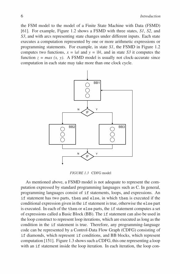
As mentioned above, a FSMD model is not adequate to represent the com-putation expressed by standard programming languages such as C. In general,programming languages consist of if statements, loops, and expressions. Anif statement has two parts, then and else, in which then is executed if theconditional expression given in the if statement is true, otherwise the else partis executed. In each of the then or else parts, the if statement computes a setof expressions called a Basic Block (BB). The if statement can also be used inthe loop construct to represent loop iterations, which are executed as long as thecondition in the if statement is true. Therefore, any programming-languagecode can be represented by a Control-Data Flow Graph (CDFG) consisting ofif diamonds, which represent if conditions, and BB blocks, which representcomputation [151]. Figure 1.3 shows such a CDFG, this one representing a loopwith an if statement inside the loop iteration. In each iteration, the loop con-
Abstraction Levels 7
struct executes BB1 and BB2 or BB3 depending on the value of the if statement.At the end, the loop is exited if all iterations are executed.
A CDFG shows explicitly the control dependencies between loop statements,if statements, and BBs, as well as the data dependences among operationsinside a BB. It can be converted to a FSMD by assigning a state to each BBand one state for the computation of each if conditional. Note that each statein such a FSMD may need several clock cycles to execute its assigned BBor if condition. Therefore, a CDFG can be considersd to be a FSMD withsuperstates, which require multiple clock cycles to execute.
A standard or custom PE can be also described with an Instruction Set(IS) flow chart that describes the fetch, decode, and execute stages of eachinstruction. A partial IS flow chart is given in Figure 1.4. The fetch stageconsists of fetching the new instruction into the Instruction Register (IR)(IR←Mem[PC]) and incrementing the Program Counter (PC ← PC + 1).In the decode stage, we decode the type and mode of the fetched instruction. InFigure 1.4, there are four types of instructions: register, memory, branch, andmiscellaneous instructions. In the case of memory instructions, there are fourmodes: immediate, direct, relative, and indirect. Each mode contains load andstore instructions. Each instruction execution is in turn described by a BB, whichmay take several clock cycles to execute, depending on the processor imple-mentation structure. For example, the memory-store instruction with indirectaddressing computes an Effective Address (EA) by fetching the next instructionpointed to by the PC and uses it to fetch the address of the memory locationin which the data will be stored (EA ← Mem[Mem[PC]]). Then it storesthe data from the Register File (RF) indicated by the Src1 part of the instruc-tion (RF [Src1]) into the memory at location EA (Mem[EA] ← RF [Src1]).Finally, it increments the PC (PC ← PC + 1) and goes to the fetch phase.
The above-described IS flow chart can be converted to a FSMD, where eachof the fetch, decode, and execute stages may need one or more states or clockcycles to execute.
In addition to FSMD, CDFG, and IS flow-chart models, other representationscan be used to specify the behavior of a PE. They provide differing types of theinformation needed for the synthesis of PEs. The guideline for choosing oneover the other is that more detailed information makes PE synthesis easier.
1.2.3 PROCESSOR-LEVEL STRUCTURAL MODELA processor’s behavioral model, whether defined by a program in C, CDFG,
FSMD, or by an IS, can be implemented with a set of register-transfer compo-nents; such a structural model usually consists of a controller and a datapath.A datapath consists of a set of storage elements (such as registers, register files,and memories), a set of functional units (such as ALUs, multipliers, shifters, and

8 Introduction
IR ← M e m [P C ]P C ← P C +I
3 2 1 0T y p e
Re g i s t e r I n s t r u c t i o n sM e m o r y I n s t r u c t i o n s
M o d e 3 2 1 0
RF [D e s t ] ← M e m [P C ]P C ← P C +1L/S
1 0
B r a n c h In s t r u c t i o n sM i s c . In s t r u c t i o n s
Lo a d D i r e c t
L/S1 0
E A ← M e m [P C ]RF [D e s t ] ← M e m [E A ]
P C ← P C +1
E A ← M e m [P C ]M e m [E A ] ← RF [Sr c 1]
P C ← P C +1
Lo a d
St o r e L/S
1 0
Re l a t i v e
E A ← M e m [P C ] + RF [Sr c 2]RF [D e s t ] ← M e m [E A ]
P C ← P C +1Lo a d
St o r e A R ← M e m [P C ] + RF [Sr c 2]M e m [A R] ← RF [Sr c 1]
P C ← P C +1L/S
1 0
In d i r e c t
E A ← M e m [M e m [P C ]] RF [D e s t ] ← M e m [E A ]
P C ← P C +1Lo a d
St o r e E A ← M e m [M e m [P C ]] M e m [E A ] ← RF [Sr c 1]
P C ← P C +1
Im m e d i a t e
FIGURE 1.4 Instruction-set flow chart
other custom functional units), and a set of busses. All of these register-transfercomponents may be allocated in different quantities and types and connectedarbitrarily through busses or a network-on-chip (NOC). Each component maytake one or more clock cycles to execute, each component may be pipelined,and each component may have input or output latches or registers. In addition,
Abstraction Levels 9
B1B2
A L U M e m o r y
R F / S c r a t c h p a d
M U L
B3
A G
PC
CW
Status
...
c o n s t
o f f s e t
s t a t u s
a d d r e s s
C M e m
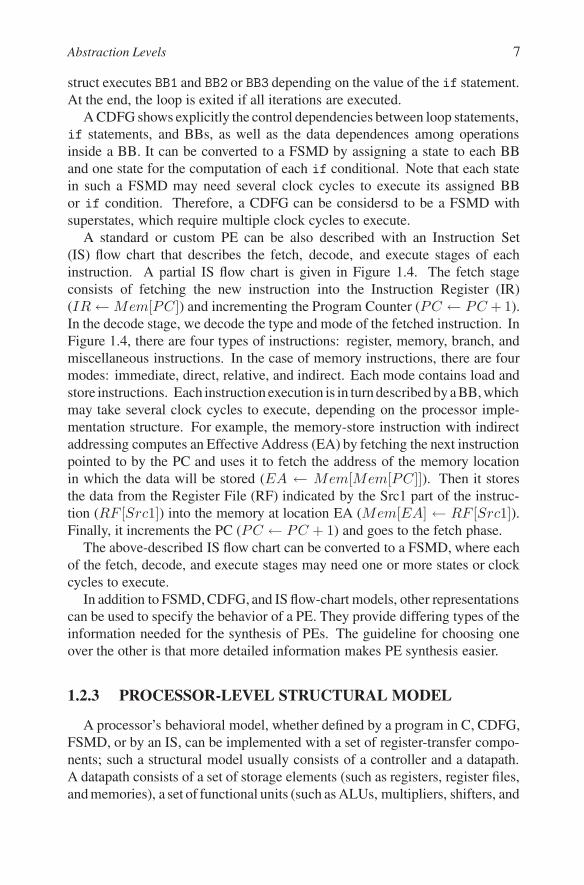
FIGURE 1.5 Processor structural model
the entire datapath can be pipelined in several stages in addition to compo-nents being pipelined by themselves. The choice of components and datapathstructure depends on the metrics to be optimized for particular implementation.
An example of such a datapath is shown in Figure 1.5. It consists of a setof registers and a Register file (RF) or a Scratchpad memory. These storageelements are connected to the functional units ALU and MUL, and to a Memoryby three busses, B1, B2, and B3. Each of these units has input and outputregisters. An ALU can execute an arithmetic or logic operation in one clockcycle from its input to its output register, while a two-stage pipelined multiplierMUL needs three clock cycles from its input to its output register. On the otherhand, Memory is not pipelined and requires two clock cycles from its addressregister to the output data register. In addition to pipelined functional units suchas the MUL, the whole datapath itself is pipelined. In such pipelined datapatheach operation may take several clock cycles to execute. For example, it takesthree clock cycles from the RF through the ALU input register, the ALU outputregister, and back to the RF. On the other hand, it takes five clock cycles throughthe MUL, since the MUL is pipelined itself. In order to speed up the executionfor complex expressions such as a(b+ c), the datapath allows (b+ c) to be sentdirectly to the MUL through a data-forwarding path without going back to RF.In Figure 1.5, such a path is shown going from the ALU output into the leftinput register of the MUL. At the same time, this path can also be implementedby a connection from the ALU output register to the left MUL input. In thiscase, we need a short bus, usually implemented with a selector, to select theALU output register or the MUL input register as the left inputs to the MUL. Asimilar selector is also shown for the Memory-address input, which may comefrom the address register or the MUL output register.
The controller defines the state of the processor clock cycle per clock cycleand issues the control signals for the datapath accordingly. The structure of the

10 Introduction
controller and its implementation depends on whether the processor is a stan-dard processor (such as Xeon, ARM, or a DSP) or a custom-design processoror Intellectual Property (IP) function specifically synthesized for a particularapplication and platform. In the case of a standard processor, the controller isprogrammable with a program counter (PC), program memory (PMem), and anaddress generator (AG) that defines the next address to be loaded into the PC.On each clock cycle, an instruction is fetched from the program memory at theaddress specified by the PC, loaded into an instruction register (IR), decoded,and then the decoded control signals are applied to the datapath for instructionexecution. The results of the conditional evaluation, called status signals, areapplied to the AG for selection of the next instruction. Like the datapath, thecontroller can be pipelined by introducing a status register and pipelining in-structions from the PC to the IR, through the Datapath and status register andthen back to the PC.
In the case of specific IPs or IF components, the controller could be imple-mented with hardwired logic gates. In terms of digital-design terminology, thePC is then called a State register, the program memory is called output logic,and the AG is called next-state logic.
In the case of specific custom processors, the controller can be implementedwith programmability concepts typical of standard processors, and control sig-nal generation of IP implementations. This is shown in Figure 1.5, in whichprogram memory is replaced with control memory (CMem) and instructionregister with control word register (CW). CMem stores decoded control wordsinstead of instructions. Figure 1.5 also illustrates how the whole processor ispipelined, including the control and datapath pipelining. On each clock cycle,one control word is fetched from CMem and stored in the CW register. Thenthe data in the RF are forwarded to a functional unit input register in the nextclock cycle, and after one or more clock cycles, the result is stored in the outputregister and/or in the status register. Finally, in the next clock cycle, the value inthe status register is used to select the new address for the PC, while the resultfrom the output register is stored back into the RF or forwarded to another inputregister.
Selecting components and the structure of a PE and defining register-transferoperations performed in each clock cycle is the task of processor-level synthesis.
1.2.4 PROCESSOR-LEVEL SYNTHESISSynthesis of standard processors starts with the instruction set (IS) of the
processor. In order to achieve the highest processor performance this processis done manually since standard processors try to achieve the highest perfor-mance and minimal power consumption at minimal cost. The second reason forsynthesizing processors manually is to minimize the design size and therefore

Abstraction Levels 11
Processor model
Component + connection selectionCy cle-a ccu r a te sch ed u ling
V a r ia b le b ind ingO per a tion B ind ing
B u s B ind ingContr oller S y nth esis
P r ocessor
Processor st ru ct u re
M od el R ef inement
B1B2
A L U M e m o r y
R F / S c r a t c h p a d
M U L
B3
A G
PC
CW
Status
...
c o n s t
o f f s e ts t a t u sa d d r e s s
C M e mIF
IF
B B 1
B B 2 B B 3
Y
YN
N
FIGURE 1.6 Processor synthesis
fabrication cost for high-volume production. In contrast, the design or synthesisof a custom processor or a custom IP starts with the C code of an algorithm,which is usually converted to the corresponding CDFG or FSMD model be-fore synthesis and ends up with a custom processor containing the number andtype of components connected as required by the given behavioral model. Thisgeneration is usually called high-level synthesis or register-transfer synthesisor occasionally just processor synthesis. It consists of five individual tasks.
(a) Allocation of components and connections. In processor synthesis, thecomponents are selected from the register-transfer library. It is impor-tant to select at least one component for each operation in the behavioralmodel. Also, it may be necessary to select components that implement somefrequently-used functions in the behavioral model. The library must alsoinclude a component’s characteristics and its metrics, which will be usedby the other synthesis tasks. The connectivity among components can beadded after binding and scheduling tasks; that way we end up with minimalconnectivity. However, we do not know the exact connectivity delays duringbinding and scheduling. Therefore, it is convenient to also add connections,buses, or a network on a chip, which will allow us to estimate more preciselyall the delays.

12 Introduction
(b) Cycle-accurate scheduling. All operations required in the behavioralmodel must be scheduled into cycles. In other words, for each operation,such as a = b op c, the variables b and c must be read from their storagecomponents and brought to the input of a functional unit that can executeoperation op, and after operation op is executed in the functional unit theresult must be brought to its storage destination. Furthermore, each BBin the given behavioral model may be scheduled into several clock cycleswhere some of the operations can even be scheduled in the same clock cycleif the datapath structure allows such parallelism. Note that each operationby itself may take several clock cycles in a pipelined datapath.
(c) Binding of variables, operations and transfers. Each variable must bebound to a storage unit. In addition, several variables with non-overlappinglife-times can be bound to the same storage units to save on storage cost.Operations in the behavioral model must be bound to one of the functionalunits capable of executing this operation. If there are several units with suchcapability, the binding algorithm must optimize the selection. Storage andfunctional unit binding also depends on connectivity binding, since for everyvariable and every operation in each clock cycle there must be a connectionbetween the storage component and the functional unit and back to a storagecomponent to which variables and operation are bound.
(d) Synthesis of controller. The controller can be programmable with a read-write program memory or just a read-only memory for fixed-functionalityIPs. The controller can be also implemented with logic gates for smallcontrol functions. As mentioned earlier, the program memory can storeinstructions or just control words which may be longer then instructions butrequire no decoding.
(e) Model refinement. A new processor model can be generated in severaldifferent styles with complete, partial, or no binding. For example, thestatement a = b + c executing in state (n) can be written:
(1) without any binding:a = b + c;
(2) with storage binding of a to RF(1), b to RF(3), and c to RF(4):RF(1) = RF(3) + RF(4);
(3) with storage and functional unit binding with + bound to ALU1:RF(1) = ALU1(+,RF(3),RF(4));
(4) or with storage, functional unit, and connectivity binding:Bus1 = RF(3); Bus2 = RF(4); Bus3 = ALU1
(+,Bus1,Bus2); RF(1) = Bus3;

Abstraction Levels 13
A structural model can be also written as a netlist of register-transfer compo-nents, in which each component is defined by its behavior from the componentlibrary.
Tasks (a), (b), and (c) can be performed together or in any specific order, butthey are interdependent. If they are performed together, the synthesis algorithmbecomes very complex and unpredictable. One strategy is to perform allocationfirst, followed by binding and then scheduling. Another possibility is to do acomplete allocation first, followed by storage binding, while combining unitand connectivity binding with scheduling.
Any of the above tasks can be performed manually or automatically. If theyare all done automatically, we call the above process processor-level or high-level synthesis. On the other hand, if (a) to (d) are performed manually andonly (e) is done automatically, we call the process model refinement. Obviously,many other strategies are possible, as demonstrated by the number of design-automation tools available that perform some of the above tasks automaticallyand leave the rest for the designer to complete.
c1
P5
P3
P4
dP1
P2
d
c2
FIGURE 1.7 System behavioral model
1.2.5 SYSTEM-LEVEL BEHAVIORAL MODELProcessor-level behavioral models such as the CDFG can be used for speci-
fying a single processor, but will not suffice for describing a complete systemthat consist of many communicating processors. A system-level model mustrepresent multiple processes running in parallel in SW and HW. The easiestway to do this is to use a model which retains the concept of states and transi-tions as in a FSM but which extends the computation in each state to includeprocesses or procedures written in a programming language such as C/C++.Furthermore, in order to represent a many-processor platform working in paral-lel or in pipelined mode, we must introduce concurrency and pipelining. Sinceprocesses in a system run concurrently, we need a synchronization mechanismfor data exchange, such as the concept of a channel, to encapsulate data com-

14 Introduction
munication. Also, we need a model which supports hierarchy, so as to allowdesigners to write complex system specifications without difficulty. Figure 1.7illustrates such a model of hierarchical sequential-parallel processes, which isusually called a Process State Machine (PSM). This particular PSM is a system-level behavior or system specification, consisting of processes P1 to P5. Thesystem starts with P1, which in turn triggers process P2 if condition d is true, oranother process consisting of P3, P4, and P5 if condition d is not true. P3 andP4 run sequentially and in parallel with P5, as indicated by the vertical dashedline. When either P2 is finished or the sequential-parallel composition of P3,P4, and P5 is finished, the execution ends.
1.2.6 SYSTEM STRUCTURAL MODELA system-level structural model is a block diagram or a netlist of system
components used for computation, storage, and communication. ProcessingElements (PEs) can be standard processors or custom-made processors. Theycan also be application-specific processors or any other imported IPs or special-functions hardware components. Storage components are local or shared mem-ories which may also be included in other processing components. Commu-nication Elements (CE) are buses or routers possibly connected in a Network-on-Chip (NOC). If input-output protocols of some system component do notmatch, we will need to insert Interface Components (IF) such as transducers,bridges, arbiters, and interrupt controllers. Figure 1.8 shows a simple systemplatform consisting of a CPU processor with a local memory, an IP component,a specially-designed custom HW component (HW), and the shared memory(Mem). They are all connected through two buses, the CPU bus and IP bus.Since CPU and IP buses use different protocols, a special IF unit (Bridge) isincluded. The HW unit has the IF for the CPU bus protocol already built intoit. Since the CPU bus has CPU and HW components competing for the bus,a special IF component (Arbiter) is added to grant bus access to one of therequesting components.
A system structural model is generated from the given behavioral model bythe process called system synthesis.
1.2.7 SYSTEM SYNTHESISSystem synthesis starts with system-level behavioral model, such as the one
shown in Figure 1.7, and generates the system structure, which consists of stan-dard or custom PEs, CEs, and SW/HW IF components, as shown in Figure 1.8.Standard components, including their functionality and structure, can be foundin the system-level component library, while custom components must be de-

Abstraction Levels 15
Bridg
e
P1 P3
CPU M e m
H W I P
P5
C 1, C 2C 1, C 2Ar
biter
P4P2
C 1, C 2C 1, C 2CPU B u s I P B u s
FIGURE 1.8 System structural model
fined and synthesized on the processor level before they can be included in thelibrary. According to the given definition, the behavioral model is a usually acomposition of two objects: processes and channels. The structural model, onthe other hand, uses different objects: processes are executed by PEs such asstandard processors, custom processors, and IPs, and channels are implementedby buses or NoCs with well-defined protocols. The behavioral model can beconverted into an optimized system platform by the following set of tasks, asshown in Figure 1.9:
(a) Profiling and estimation. Synthesis starts by profiling the application codein each process and collecting statistics about types and frequency of op-erations, bus transfers, function calls, memory accesses, and about otherstatistics that are then used to estimate design metrics for the optimizationof the platform or application code. These estimated metrics include per-formance, cost, bus traffic, power consumption, memory sizes, security,reliability, fault tolerance, among others;
(b) Component and connection allocation. Next, components from the libraryof standard and custom processors, memories, IPs, and custom-functionalitycomponents must be allocated and connected with buses through bridges orrouters. It is also possible to start with a completely defined platform, whichis very useful for application and system software upgrades and productversioning;
(c) Process and channel binding. Processes are assigned to PEs, variablesto memories (local and global), and channels to busses. This requires anoptimized partitioning of processes, variables, and connection traffic to min-imize the platform-design metrics;

16 Introduction
(d) Process scheduling. Parallel processes running on the same PE must bestatically or dynamically scheduled. This requires generating a real-timeoperating system for dynamic scheduling;
(e) IF component insertion. Required IF components must be inserted intothe platform from a library or synthesized on the processor level beforebeing added to the library. Such additional SW IF components includesystem firmware components such as device drivers, routing, messaging andinterrupt routines, and HW IF components to connect platform componentswith incompatible protocols and facilitate communication synchronizationor message queuing. Examples of these HW IF components would includeinterrupt controllers and memory controllers.
(f) Model refinement. The final step in converting a behavioral model into anoptimized system platform consists of refining the behavioral model intoa structural model in order to reflect all the platform decisions, as well asadding newly synthesized SW, HW, and IF components.
Profiling + EstimationC omp one nt A lloc ation
M od e l R e fine me nt
Proc e ss + C h anne l B ind ingS W / H W I F D e finition
S y ste m
S c h e d u lingC onne c tion A lloc ation
c1
P5
P3
P4
dP1
P2
d
c2
Bridg
e
P1 P3
CPU M e m
H W I P
P5
C 1, C 2C 1, C 2
Arbit
er
P4P2
C 1, C 2C 1, C 2CPU B u s I P B u s
FIGURE 1.9 System synthesis
The above tasks can be performed automatically or manually. Tasks (b)-(e) are usually performed by designers, while tasks (a) and (f) are better doneautomatically since they require too many pain-staking and error-prone statis-tical accounting or code construction. Once the refinement is performed, the

System Design Methodology 17
structural model can be validated by simulation quite efficiently since all thecomponent behaviors are described by high-level functional models. More for-mal verification of the behavioral and structural models is also possible if weformalize the refinement rules.
In order to generate a cycle-accurate model, however, we must replace eachfunctional model of each component with a cycle-accurate structural model forcustom HW or IS model for standard processors executing compiled applicationcode. Once we have this model, we can refine it further into a cycle-accuratemodel by performing RTL synthesis for custom processors or custom IFs, andby compiling the processes assigned to standard processors to the instruction-setlevel and inserting an IS simulator to execute the compiled instruction stream.We also have to synthesize system software or firmware for the standard andcustom processors. After RTL/IS refinement, we end up with a cycle-accuratemodel of the entire system. This model can be downloaded to a FPGA board byusing standard CAD tools provided by the board supplier. This way we can ob-tain a system prototype. If all synthesis and refinement tasks are automated, thesystem prototype can be generated in a few weeks, depending on the expertiseof the system and application designers.
Specs
A l g o r i t h m s
Capture & S i m ul ate
Specs
A l g o r i t h m s
D es c ri b e & S y n th es i z e
E x ecu t a b l e Spec
A l g o r i t h m s
S pec i f y , E x pl o re & R ef i n e
A r ch i t ect u r eN et w o r kSW /H WL o g i cP h y si ca l
S W ? S W ?
D esi g nL o g i cP h y si ca l
D esi g nL o g i cP h y si ca l
M a n u f a ct u r i n g M a n u f a ct u r i n g M a n u f a ct u r i n g
1 9 6 0 's 1 9 8 0 's 2 0 0 0 's
Functionality
S i m ulate S i m ulate
D e s cr i b e
A l g o r ith m s
C onne ctiv ityP r otocols
P e r f or m ance
T im ing
S ys te m G ap
FIGURE 1.10 Evolution of design flow over the past 50 years

18 Introduction
1.3 SYSTEM DESIGN METHODOLOGYDesign flow has been changing with the increase in system complexity over
the past half-century. We can indicate several periods which resulted in drasticchanges in design flow, tools, and methodology, as shown in Figure 1.10.
(a) Capture-and-Simulate methodology (1960s to 1980s). In this method-ology, software and hardware design was separated by a so-called systemgap. SW designers tested some algorithms and occasionally wrote therequirements document and the initial specification. This specificationwas given to the HW designers, who began the system design with ablock diagram based off of it. They did not, however, know whethertheir design would satisfy the specification until the gate-level design wasproduced. When the gate netlist was captured and simulated, designerscould determine whether the system worked as specified. Usually thiswas not the case, and therefore the specification was usually changed toaccommodate implementation capabilities. This approach started the myththat specification is never complete. It took many years for designers torealize that a specification is independent from its implementation, meaningthat specification can be always upgraded, as can its implementation.
The main obstacle to closing the system gap between SW and HW , andtherefore between specification and implementation, was the design flowin which designers waited until the gate level design was finished beforeverifying the system specification. In such a design flow there were toomany levels of abstraction between system specification and gate leveldesign for SW designers to get involved.
Since designers captured the design description at the end of the designcycle for simulation purposes only, this methodology is called capture-and-simulate. Note that there was no verifiable documentation before thecaptured gate level design, since most of the design decisions were storedinformally in the designers’ minds.
(b) Describe-and-Synthesize methodology (late 1980s to late 1990s).The 1980s brought us tools for logic synthesis which have significantlyaltered design flow, since the behavior and structure of a design wereboth captured on the logic level. Designers specified first what theywanted in Boolean equations or FSM descriptions, and then the synthesistools generated the implementation in terms of a logic-level netlists. Inthis methodology therefore, the behavior or function comes first, andthe structure or implementation comes afterwards. Moreover, both of

System Design Methodology 19
these descriptions are simulatable, which is an marked improvement overCapture-and-Simulate methodology, because it permits much more efficientverification; it makes it possible to verify the descriptions’ equivalencesince both descriptions can in principle be reduced to a canonical form.However, today’s designs are too large for this kind of equivalence checking.
By the late 1990s, the logic level had been abstracted to the Register-TransferLevel (RTL) with the introduction of cycle-accurate modeling and synthesis.Therefore, we now have two abstraction levels (RTL and logic levels) andtwo different models on each level (behavioral and structural). However,the system gap still persists because there was not relation between RTL andhigher system level.
(c) Specify, Explore-and-Refine methodology (early 2000s to present). Inorder to close this gap, we must increase the level of abstraction fromthe RTL to the system level (SL) and to introduce a methodology thatincludes both SW and HW. On the SL, we can start with an executablespecification that represents the system behavior; we can then extend thesystem-level methodology to include several models with different detailsthat correspond to different design decisions. Each model is used to provesome system property: functionality, application algorithms, connectivity,communication, synchronization, coherence, routing, performance, orsome design metric such as performance, power, and so on. So we mustdeal with several models in order to verify the impact of design decisionson every metric starting from an executable specification down to theRTL and further to the physical design. We can consider each model asa specification for the next level model, in which more implementationdetail is added after more design decisions are made. We can label this aSpecify-Explore-Refine (SER) methodology [63, 100], in that it consists ofa sequence of models in which each model is a refinement of the previous.Thus SER methodology follows the natural design process in which de-signers specify the intent first, then explore possibilities, and finally refinethe model according to their decisions. SER flow can therefore be viewedas several iterations of the basic Describe-and-Synthesize methodology.
In order to define a reasonable SER methodology, we need to overview thestatus of methodologies presently in use, their shortcomings, and how toupgrade them to the system level. More detailed explanations will be givenin Chapter 2.

20 Introduction
case X i sw h en X1=>
. . .
w h en X2=>
F i n i t e s t a t e m a c h i n e
C o n t r o l l e r
3.4 152.7 15----
L o o k -u p t a b l e
M e m o r y
FIGURE 1.11 Missing semantics
1.3.1 MISSING SEMANTICSWith the introduction of system-level abstraction, designers must generate
even more models. One obvious solution is to automatically refine one modelinto another. However, that requires well-defined model semantics, or, in otherwords, a good understanding what a given model means. This is not as simpleas it sounds, since design methodologies and the EDA industry have been dom-inated by simulation-based methodologies in the past. For example, the modelswritten in Hardware Description Languages (HDLs) (such as Verilog, VHDL,SystemC, and others) are simulateble, but they are not really synthesizable orverifiable. They can result in ambiguities that make automated synthesis andverification impossible, due to the unclear semantics involved. Only a well-defined subset of these languages may be synthesizable or verifiable.
As an example of this problem, we can look in Figure 1.11 at a simple casestatement available in any hardware or system modeling language. This typeof case statement can be used to model a FSM in which every case such as X1,X2, ..., represents a state in which all its next states are defined. This type ofcase statement can also be used to model a look-up table, in which every caseX1, X2, ..., indicates a location in the memory that contains a value in the table.Therefore, we can use the same case statement with the same variables andformat to describe two completely different components. Unfortunately, FSMsand look-up tables require completely different implementations: a FSM canbe implemented with a controller or with logic gates, while a look-up table isusually implemented with some kind of memory. It is also possible to implementa FSM with a memory or a table using logic gates. However, this would not bea very efficient implementation, and it would not be acceptable to any designer.So a model which uses case statements to model FSMs and tables is good for

System Design Methodology 21
simulation but not for implementation because neither a designer nor a synthesistool can determine which type of structure was described by the case statement.
The lesson is that contemporary modeling languages allow modelers to de-scribe the design in many different ways and to use the same description fordifferent designs details. But for automatic refinement, synthesis, and verifica-tion, we need clean and unambiguous semantic which uniquely represents allthe system concepts in a given model. Such a clean semantic is missing frommost of the simulation-oriented languages. In order to have well-defined se-mantics, we need to introduce some form of formalism to models and modelinglanguages.
1.3.2 MODEL ALGEBRAWe can see than that in order to find an acceptable methodology and develop
adequate system design tools, we need to clearly define the semantics of thedifferent design models and the rules for model refinement. Generally speak-ing, every model is a set of objects and composition rules. In order to find anadequate model structure, we can look to some standard, well-defined algo-rithmic structures such as arithmetic algebra, which consists of objects such asnumbers and operations such as addition and multiplication; we can representthis as, numbering here
Algebra :< objects, operations >
Algebra’s composition rules allow for the creation of hierarchical expressionssuch as a ∗ (b + c) and their transformation. For example, by multiplying awith the (b + c) we get a new expression numbering here
a ∗ (b + c) = a ∗ b + a ∗ c
The equivalence of these two expressions allows designers to perform op-timization using arithmetic algebra rules. The expression on the left requiresone multiplier and one adder and may take two clock cycles, assuming eachoperation takes one clock cycle. On the other hand, the expression on the rightrequires two multipliers and one adder; it may also take two clock cycles tocomplete. In this case, the expression on the left requires fewer resources forthe same execution time. In case we are limited to only one adder and one multi-plier, the expression on the right would take three clock cycles. In this case, theexpression on the left would execute faster for the given resources. Thus, arith-metic algebra allows for the creation of expressions and their transformation toequivalent expressions for the optimization of some design metrics.
We can also create model algebra consisting of modeling objects and com-position rules similar to those of arithmetic algebra, in that numbering here
ModelAlgebra :< objects, compositions >

22 Introduction
P1
P2 P3
P1
P2 P3
PE 1 PE 2
=
FIGURE 1.12 Model equivalence
The most important objects for a model are processes or behaviors and com-munication channels. Using model algebra composition rules, objects can becomposed hierarchically in sequential and concurrent fashion. The left sideof Figure 1.12 for example shows a sequential composition of process P1 fol-lowed by a concurrent composition of processes P2 and P3. After decidingthat the system platform will have two processing elements, PE1 and PE2, andmapping P1 and P2 to PE1, and P3 to PE2, the original model must be refinedto reflect these platform and mapping decisions. The necessary transforma-tions include the introduction of another level into the hierarchy to reflect thegiven platform architecture and a new communication channel for data transfer.The new channel, in addition to transferring data, preserves the sequentialityof P1 and P3, since data is transferred after P1 finished and P3 can not startbefore data becomes available. Thus the model on the right side is equivalent tothe model on the left side. Thus, model algebra allows creation of models andproving their equivalence by allowing model transformations that preserve theirexecution semantics. In other words, model algebra is an enabling technologyfor system synthesis and verification.
Model algebra also enables the development of a Specify-Explore-Refine(SER) methodology, as shown in Figure 1.13. With model algebra in place, wecan define the semantic and style of each model and define a model transforma-tion or refinement for each design decision. Therefore, after some estimationand exploration, a design decision can be made which will in turn result in amodel transformation that preserves execution equivalence. A model transfor-mation usually results in the replacement of one object by several other objectsor in a re-composition of some objects. In case of system-level design, as shownin Figure 1.13, we start with the system executable specification, generate sev-eral intermediate models, and end up with a cycle-accurate model that can bedownloaded to a FPGA board with standard FPGA tools or synthesized into anASIC with adequate ASIC tools.

System-Level Models 23
System specification mod el
C ycl e accu r ate impl ementation mod el
SER
Intermediate models
Design decisions
M odel r ef inem ent
R ep l a cem ent or r e-com p osit ion
FIGURE 1.13 SER Methodology
1.4 SYSTEM-LEVEL MODELSIn the most common industrial-system design flow today, designers are using
different modeling styles and different numbers of models to demonstrate thevalidity of their software or hardware. The key question facing a designer ishow many models are really needed. At one extreme is the argument that weneed one model for each level of abstraction and each design metric. Sincedifferent metrics are used by different design groups, this strategy will result inmany incompatible models in the same organization and will eventually breakdown the product design flow. At the other extreme, some designers claim thatone model is good enough for several abstraction levels and many metrics. Thisstrategy generates a very complex and overly-detailed model, while degradingits comprehensibility and, therefore decreasing design productivity.
In order to identify the minimum number of models necessary for systemdesign, we must look into the profiles and expertise of the designers of suchsystems. There are three types of designers: application, system, and imple-mentation designers.
Application designers have a good knowledge of their application domain,application structures, and application algorithms, but only a basic knowledgeof system design and technology;
System designers have a good knowledge of system organizations, multi-processor architectures and their operations, and system-level SW and HW, butoverview knowledge of application and implementation technology;

24 Introduction
Implementation designers have a specialized knowledge of specific com-ponents, implementation methods and technology on abstraction levels belowthan the system level, but minimal knowledge of application or overall systemoperation.
According to these three levels of design expertise, at least three systemmodels are necessary for system design:
(a) Specification Model (SM) is used by application designers to prove thattheir algorithms work on a given system platform. They also modify itfor more efficient task and channel partitioning, mapping, and schedulingonce a possible platform is defined. This model is also used for adding newfeatures, functions, and upgrades after the initial deployment of the productinto the market.
(b) Transaction-Level Model (TLM) is used by system designers to estimatedesign metrics (such as performance, cost, traffic, communication, powerconsumption, reliability, among others) and to explore different implemen-tations (component selection, connectivity, system firmware, operating-system selection, and different types of interfaces).
(c) Cycle-Accurate Model (CAM) is used by HW designers to verify the cor-rectness of the generated system HW components (such as custom pro-cessors, interfaces, memory controllers, interrupt controllers, bridges, ar-biters, and similar components) and by SW designers to verify the systemfirmware (such as task scheduling, data transfer, synchronization, interruptprocedures, and routing).
Given the ongoing advances in technology and systems, the distinction be-tween HW and SW designers is blurring; every embedded system includes bothhardware and software, and furthermore, what is in hardware today could bemoved to software in the next version of the product and vice versa. Any ofabove three essential models can be used by either of the application, SW orHW groups depending on the company’s organization. Since the above modelsare defined according to designers’ expertise, we may want to explore whateach of these models contains and how it is used.
The SM contains the application code and the system requirements, as shownin Figure 1.7, in which the application code is defined by a PSM model of com-putation. This model is used to specify application algorithms and to optimizethe application code for mapping to a platform when the platform is defined. Inother words, the application code must be broken down into processes commu-nicating through channels in a way that will optimize local communication andminimize long-distance communication after platform mapping. Similarly, theapplication code must be divided into processes whose computation structurewill match the PE types in the platform so as to facilitate performance opti-

System-Level Models 25
mization. In the same way, the application code can be restructured to matchother design metrics. This code restructuring may take several iterations.
Platform architecture consists of a set of PEs and a set of CEs selected fromthe library or defined by the user, as shown in Figure 1.8. The platform ar-chitecture can be given with the SM or defined partially or completely duringthe system synthesis process shown in Figure 1.9. More components or con-nections can be added or modified at a later stage for the optimization of somemetrics. During synthesis, processes are mapped to the architecture’s PEs, thatis, its CPUs, HW components, and IPs. Variables are mapped to memory com-ponents, either local to PEs or shared. Channels between processes are mappedto routes consisting of buses and bridges, as described in the previous sections.
CPU Bus
P1 P3
O S
P5
CPU M e m
I PH W
I P Bus
Br i d g e
P4P2
FIGURE 1.14 System TLM
The given or generated platform with its mapped application processes andchannels defines the system structure after system synthesis, as shown previ-ously in Figure 1.9. This system structure is usually modeled with a TLM,which Figure 1.14 illustrates. This TLM has the same components as Fig-ure 1.9 but with added bus interface functions and with channels combined intobuses. Channels C1 and C2 use the CPU bus and the IP bus through the bridge,which converts the CPU bus protocol into IP bus protocol. On the system soft-ware side, the CPU has the operating system (OS) model added, as well ascommunication drivers for the CPU bus.
The TLM can be un-timed or timed. For the timed TLM, we need to profilethe application code and generate performance estimates for each process onits corresponding component, in addition to estimating the time needed to sendeach message on its corresponding route. For example, for a message sent from

26 Introduction
P3 to P5, we must add time estimates for the message transfer over the CPUbus, protocol conversion in the bridge and the transfer over the IP bus.
As mentioned earlier, a TLM is used to explore different SM structures,different platform architectures, each with different numbers and types of com-ponents and different SM mappings to platform architectures. For example,we may want to restructure a SM for a given platform and a given mapping.On the other hand, for any given SM and component library, we may try togenerate an optimal platform for some given metric. Similarly, for a given SMand platform, we may try to find an optimal mapping for a given metric. Inan extreme case, we may want to simultaneously optimize the SM structureor application code, platform architecture, and the mapping for one or severalmetrics. As mentioned earlier, TLMs allow us to perform quickly and withreasonable accuracy each of these disparate optimization scenarios, which willbe described in more detail in Chapter 4.
CPU Mem
B r i d g e
H W I P
A r b i t erHALR T O SEXE I C
Program
FIGURE 1.15 System CAM
A TLM serves for exploration of the platform structure and estimation ofsystem quality metrics. It is a system-level model. In order to generate aprototype or a product we need to lower the abstraction level to the processorlevel and generate a CAM of the entire system, example of which is shownin Figure 1.15. From a TLM model, we can generate the CAM by refiningthe functionality of each component to the cycle-accurate or register-transferlevel (RTL) description. For custom HW components we need to generate RTLusing processor-level synthesis that has been described in Figure 1.6. For IFcomponents such as arbiters, interrupt controllers, memory controllers, and CDcomponents, such as bridges and routers, we can use the same processor-level

Platform Design 27
synthesis. In case of IP components we can replace functional description withthe RTL description that is provided by the IP suppliers. In case of standardprocessors we can compile application and system code into an instructionstream to be executed on the processor’s RTL model or IS model. In case ofsystem prototyping, the instruction stream is executed on the processor availableon the prototyping board. CAM model also includes models of system SWincluding communication drivers, libraries, and RTOS.
Depending on the prototype target, the CAM must include all files that willbe needed by the respective FPGA board design tools. These files and the CAMmodel are exported to the FPGA design environment where implementation de-signers compile the SW and perform synthesis for the HW components. Finally,a bit-stream is generated that directly programs the FPGA with the prototype.This programmed FPGA typically has a hyper-terminal user interface that canbe used to debug the prototype.
In a different scenario, a CAM can co-simulate with an instruction-set sim-ulator and a hardware-description language simulator. In this case, an ISS isinserted and all the SW code is compiled into binaries and simulated with theinserted ISS while the hardware is simulated on the RTL level in Verilog orVHDL with an appropriate co-simulator.
Each of these different model types, SM, TLM, and CAM, has a place inevery system design-flow. Their roles in different design methodologies willbe elaborated in Chapter 2 and Chapter 3.
1.5 PLATFORM DESIGNToday’s platforms come in a variety of forms and shapes. Usually they have
one or more standard processors, a processor for multi-media, several differ-ent specialty IPs, and a multitude of special IFs for different communicationstandards. Although platforms today use a variety of components, platformstructure is not standardized. System-design automation is possible if we canlimit the number of components and the structure of each platform.
In order to do that we can identify a small number of necessary componenttypes:
(a) processing components (PEs), such as standard or custom processors, forcomputation tasks;
(b) storage components, such as local and global memories, for data storage;
(c) communication components (CEs), such as transducers and bridges, forthe communication of data, temporary buffering of data, and translation ofone communication protocol into another;

28 Introduction
(d) interface components (IFs), such as arbiters for bus traffic regulation, DMAcontrollers for speeding up memory traffic, interrupt controllers for synchro-nization, UARTs, and others.
Bus2Bus1 Bus3
A r b i t e r 1
P E 1 AP E 1 A
T r a n sd uc e r 2-3
A r b i t e r 2
A r b i t e r 3P E 1 BP E 1 B
M e m o r y 1M e m o r y 1
P E 2A( M a st e r )P E 2A( M a st e r )
P E 3AP E 3A
M e m o r y 3M e m o r y 3
Interrupt1.1
Interrupt2 .1
P E 2B( S l a v e )P E 2B( S l a v e )
T r a n sd uc e r 1 -2T r a n sd uc e r 1 -2 Interrupt2 .2
Interrupt3 .1Interrupt3 .2
I FI FI FI F
FIGURE 1.16 Platform architecture
These four component types could be sufficient for any platform, althoughsome others (analog components, sensors) may be added for specific applicationfunctions. Basic connectivity can be accomplished with buses and transducersto convert one protocol into another if necessary. Transducers can also be usedfor routing if they can compute possible routes or if the routing is encoded in themessage. Such transducers are sometimes called routers; they can be combinedinto a variety of networks-on-chips (NOCs).
Using components (a) through (d) we can construct any system platform.Figure 1.16 gives an example of such a platform. It consists of three buses,Bus1, Bus2, and Bus3, with an arbiter on every bus. Bus1 has two PEs, PE1A and PE 1B, and one memory. Bus2 has also two PEs, PE 2A and PE 2B,where PE 2A is the bus muster. Bus3 on the other hand has one PE and onememory. There are two transducers: Transducer 1-2 between Bus1 and Bus2,and Transducer 2-3 between Bus2 and Bus3. In order for PE 1A to send amessage to PE 3A, the message must be routed through both transducers.
We can build any platform structure using PEs as computation components,memories as storage components, and buses as connectivity components. We

System Design Tools 29
can build more complex system connectivity structures by using transducers asrouters and building complex NoCs with such transducers. Finally, we concludethat four component types (a) through (d) are sufficient to build a platform of anycomplexity. The simplicity of the platform construction rules as demonstratedin Figure 1.16 enables system design automation for modeling, synthesis, andverification.
Model A
Model B
E s t i m a t i ont ool
E s t i m a t i ont ool
S y n t h es i st ool
S y n t h es i st ool
C om p on en tli b r a r y
C om p on en tli b r a r y
S i m u la t i ont ool
S i m u la t i ont oolG U I V er i f y
t oolV er i f yt ool
ti
R ef i n em en tt ool
R ef i n em en tt ool
Transforms:t1t2...
tn
FIGURE 1.17 General system environment
1.6 SYSTEM DESIGN TOOLSIn order to explore system design automation, we must look at basic system
design needs and some possible generic system tools. Using a Specify-Explore-Refine methodology, system models can be generated automatically as long asfor every design decision we can define a sequence of transformations thatwill refine the given model accordingly. Therefore, for every pair of models(such as Model A and Model B in Figure 1.17), we may make several designdecisions at once and apply a transformation sequences to refine the model. Thetool that performs that refinement is called the refinement tool. Obviously, wecan verify that the applied transformations will preserve execution equivalenceusing a verify tool that will verify each sequence of transformations. The newModel B can be also simulated and the results compared with the results fromModel A by way of a simulation tool.

30 Introduction
The design decisions which guide the refinement are made by the designerthrough a GUI, which also includes selecting the proper components for the de-sign refinement from a component library. The refinement tool may also selectcomponents during the refinement transformations when a functional descrip-tion is replaced with a structural description. In order for a designer to makecorrect design decisions, an estimation tool provides the values of different met-rics obtained from Model A. The same metrics are also provided to a synthesistool which can make design decisions automatically in case the designers arenot available or are not experienced enough to do so. This synthesis tool usesdifferent algorithms to optimize a design according to the given requirementsand metrics provided by the estimation tool.
This kind of general environment is easy to visualize or implement as longas the abstraction levels of Model A and Model B do not differ significantly inabstraction levels and Model B can be derived from model A through set ofwell-defined design decisions and the corresponding transformations. In thecase that the two models are written without clear and well-defined semantics,or without a well thought-out transformation sequence, model-based synthesisand verification is not possible.
In order to develop good automation tools, we must look at the system designprocess in general, and the system models that we described in the previoussections in particular. We identified three basic models: SM, TLM, and CAMfor three types of system designers. Therefore, we will need at least two typesof tools:
(a) a front-end tool, which is a tool for application developers who want totest their product concepts. It captures system behavior with a MoC in astandard language such as C, C++, SystemC, Matlab, UML or a similargraphic representation as an input, and it generates a functional or a timedTLM to use in design-space exploration;
(b) a back-end tool, which is a tool for SW and HW system and implementationdesigners to use in creating the SW and HW details for a given platform andfor a particular application. Such tool may take the TLM model from thefront-end and generate a CAM or PCAM in a HDL for the HW and an ISmodel for the SW, to be used for co-simulation with a HDL/IS co-simulator.The HW model can be synthesized with RTL tools while the compiled SWinstruction stream can be downloaded to selected processors in the prototypeor the final implementation of the system platform.
This sort of generic system-development tool is shown in Figure 1.18. Itconsists of a Front-End stage and a Back-End stage, which are supported bytwo types of interfaces.
The Front-End consists of two elements, System Capture and Platform De-velopment. System capture may be a graphical user interface which captures

System Design Tools 31
DecisionU ser
I nt er f a ce ( DU I )
V a l i d a t ionU ser
I nt er f a ce ( V U I )
TIMED
C r e a t e
Ma p
C o m p i l e
R e p l a c e
S e l e c t
P a r t i t i o n
C o m p i l e
De b u g g e r
S t i m u l a t e
V e r i f y
Application Tools : Compilers/Debuggers Commercial Tools : F P G A, AS I C
C Y C L E A C C U R A TE
V e r i f y
S i m u l a t e
C h e c k
C o m p i l e
Front – E ndSystem Capture + Platform Development
SW Development + H W DevelopmentB a c k – E nd
TLM
C A M
FIGURE 1.18 System tools
the definition of the platform architecture and the product application code witha SM. The Platform Development tool generates timed TLMs of the platformarchitecture which executes the product application captured by the capturetool. In order to generate a timed TLM, the Front-End tool uses an estimatorfor estimating computation time for each PE and communication time for eachmessage on a particular message route. Such timed TLMs provide reliablemetrics for early exploration of design choices. In addition, TLMmay provideestimates of other metrics, such as power, cost, and reliability. If these metricsare not satisfactory, a designer may change the type and number of components,the number and type of connections, and/or the mapping of the application codeonto different PEs and CEs. The TLM generated by the Platform Developmenttool models the platform structure and HW, as well as SW components such asRTOS.
In the Back-End, the HW Development component is used to generate acycle-accurate or RTL description of the HW components, which can be furtherrefined by commercially-available tools for ASIC or FPGA manufacturing.SW Development generates the firmware necessary to run communication andapplication SW on the platform.

32 Introduction
The Validation User Interface (VUI) is used to debug and validate the devel-oped SW and HW. To do this it uses standard tools such as compilers, debuggers,simulators, and verifiers. These validations can be done on both the TLM andCAM levels, with different validation tools for each level.
Decision User Interface (DUI) is used by designers to evaluate the qualityof the metrics generated by the estimators and to make decisions concerningplatform creation, component and connectivity selection, task scheduling, SWand HW component partitioning, model creation, and other system design de-cisions. The DUI must therefore be supported by a component database whichstores models of different components on different abstraction levels. Simi-larly, the DUI may include a synthesis tool that can generate some of designdecisions and optimize the platform for some given metrics in order to speedup system development.
The benefit of an increase in abstraction levels and possible automation is aproductivity increase of several orders of magnitude. Since models are gener-ated automatically, designers do not have to learn modeling languages or spendtime in model development. Designers make only design decisions while themodels get refined automatically. Since there is no manual involvement from thedesigner, models preserve well-defined semantics and are, therefore, synthesiz-able and verifiable with automatic tools. Furthermore, such model automationfacilitates the trend towards globally-distributed design teams, since any designchange introduced at any location can be estimated and verified automaticallyat any other location. It also enables cooperation between component suppliersand product integrators, as, for instance, in the automotive market, where manysuppliers provide hundreds of electronic control units to car manufacturers forintegration into a vehicle; model automation enables efficient negotiation andcoordinated discussion regarding integrators requirements and component sup-plier offerings. In addition to the productivity benefits, the main benefit ofmodel automation is that it does not require high-level design expertise, whichallows many application experts without detailed knowledge of embedded sys-tem design to develop systems and upgrades for their products. This also speedsup the deployment of products to the market since long redesign processes canbe avoided.
1.7 SUMMARYThe concepts presented so far seem reasonable but the main question still
remains: "Do they work?" Let’s look at them one at the time.We described a methodology that is based on well-defined models, design
decisions, and model transformations. Simple models and clear semanticsworked in the past as an enabler for the progress to the next level of abstraction.
Summary 33
For example, in 1960s, we had many different logic design styles, from resistor-transistor logic (RTL), to diode-transistor logic (DTL), to transistor-transistorlogic (TTL), and so on. Real progress in design productivity only came whenwe reduced the number of components on the chip to two types of transistors,P-type and N-type, and incorporated them into CMOS logic, which is still inuse today.
Another example of simple and clear semantics comes from the experiencesin layout design. The real progress in layout floorplanning, placement androuting algorithms, and layout tools was made when we reduced logic gates tostandard cells and routing to channel routing. Again, this simplification madelayout tools more efficient and acceptable by designers. Logic synthesis pro-vides another example of efficiency introduced by a clear and simple semantics;here the real progress was made when number of components was reduced tosimple NAND, NOR, and NOT gates. It also worked on RTL level, when thecontroller design was reduced to the FSM model for a datapath structure that wasmanually specified by the designer. Unfortunately, the definition of a simpleand clear semantics for the processor-level design, consisting of a custom con-troller and a custom datapath, is still not available. There are many C-to-RTLsynthesis tools based on FSMD models with a variety of synthesis algorithmsproviding results of varying quality. This indicates that there is still a need for aclarifying and simplifying high-level synthesis methodology and the accompa-nying tools. On the next abstraction level, the system level automation is still inits infancy. In order to automate system design, which would be the ideal, weneeded to simplify even more the components, models, and tools involved. Forthat reason, we described a possible strategy called model algebra to properlydefine models and refinements.
As proof for the success of this approach, we point to several academicand commercial system tools that have been developed for automatic modelgeneration, synthesis, and verification. The preliminary evidence testifies thatthese tools result in productivity improvements of several orders of magni-tude. In addition, the clear semantics we advocate allow easy managementof globally-distributed projects, since upgrades made anywhere in the worldcan be checked and verified everywhere. They also allows for easy productversioning and the timely creation of product derivatives, which will result inshorter time-to-market and more profitability.
As mentioned above, the complexities of embedded systems are forcing thedesign and design automation communities to rethink the design flow, modeling,synthesis, and verification of such systems. In addition, these complexities arealso requiring a more substantial and deeper change in industry and academia.The distinction between HW and SW is disappearing. What is in software in oneproduct could be in hardware in the next version of the same product. Therefore,designers of systems must be equally knowledgeable in both: SW and HW.

34 Introduction
Likewise, academia must start teaching courses in which the implementationof computing and communication concepts is presented in SW and HW in thesame course. That requires the restructuring of many courses, particularly incomputer science and computer engineering programs. In the long run, thecomputer science and computer engineering departments at our universitieswill be combined.
Similarly, the disappearing difference between SW and HW requires changesin the organizational structure of system design and manufacturing companies inany application domain. The present separation of application, system design,and SW and HW groups is not efficient. Likewise, the current simulation-based design flow is not sustainable since it requires designers to first learnthe modeling language, develop models, and then verify the design, which alltogether takes too long and decreases design productivity. The system-designmethodology of the near future must be based on solid scientific principles toenable its easy use and deployment.
In addition, the design and tool community must start changing their viewof generic design practices to concentrate on applications’ embedded systemsand their specific needs. The 1000x productivity will not come without someserious experiments. After several years of work, we are glad to see the light atthe end of the tunnel. In the succeeding chapters, we will present system designpractices that have been proven in some real success stories though always withthe understanding that more work lies ahead.