
Email From: Williams, Charles R. [Charles.Williams@pgnmail ... · FORMS: REINFORCEMENTS: EMBEDDED...
24
Franke, Mark From: Sent: To: Cc: Subject: Attachments: Williams, Charles R. [[email protected]] Tuesday, November 24, 2009 7:08 AM Lake, Louis; Thomas, George; [email protected] Herrin, Dennis W. Refute 2.7 for Review FM 2.X.ppt; Pour7291-mechanical vibration.pdf; Pour362RB-mechanical vibration.pdf; Pour528RBElevl03-mechanical vibration.pdfPour674RB-mechanical vibration.pdf; S Pour713RB-mechanical vibration.pdf; Erlin PHike Petro report 05101976.pdf; Core Bore #5 Final CTL Petrographic Report 059169 C856 (2).pdf; Interview Willie Easman.doc Mr Lake, I am resending due to difficulty with opening/reading the previous attachments. Again, this is prelim. Call me with questions. It looks like I will need to send each one as separate emails to keep from mixing documents. Thank you, Vf Charles Williams 919-516-7417
Transcript of Email From: Williams, Charles R. [Charles.Williams@pgnmail ... · FORMS: REINFORCEMENTS: EMBEDDED...
Franke, Mark
From:Sent:To:Cc:Subject:Attachments:
Williams, Charles R. [[email protected]]Tuesday, November 24, 2009 7:08 AMLake, Louis; Thomas, George; [email protected], Dennis W.Refute 2.7 for ReviewFM 2.X.ppt; Pour7291-mechanical vibration.pdf; Pour362RB-mechanical vibration.pdf;Pour528RBElevl03-mechanical vibration.pdfPour674RB-mechanical vibration.pdf; SPour713RB-mechanical vibration.pdf; Erlin PHike Petro report 05101976.pdf; Core Bore #5Final CTL Petrographic Report 059169 C856 (2).pdf; Interview Willie Easman.doc
Mr Lake,I am resending due to difficulty with opening/reading the previous attachments. Again, this is prelim. Call me withquestions. It looks like I will need to send each one as separate emails to keep from mixing documents.
Thank you, Vf
Charles Williams
919-516-7417

2.7 Inadequate Vibration during PourD0 May identify additional perspective on this issue
as RCA related efforts proceeds
Description:Concrete, especially low slump concrete, requires rigorous mechanical intervention in order to spreadthrough the forms and move around tightly spaced reinforcement. Vibration helps remove excess entrappedair and water. However, excessive vibration could result in segregation of concrete constituents, while toolittle vibration could result in voids and aggregate pockets even when the concrete slump is within spec.
Data to be Collected and Analyzed:(1) Vibration inspection reports. A sample is provided in Exhibit 1.(2) Existence of voids and aggregate pockets. (Exhibit"2zand Willie Easman interview.)(3) Segregation of concrete constituents. (Exhibit 2)(4) Conduct interviews of former plant employees if available. (Exhibit 3)
Verified Refuting Evidence: Verified Supporting Evidence:1. Adequate mechanical vibration provided. (Ex 1).2. Visual and Petrographic observations showrelatively dense matrix with air voids that do notappear excessive. (Ex. 2)3. Although several NCRs addressed voids andaggregate pockets that required corrections andwere repaired, they are more a manifestation ofslump issues than vibration (See FM 2.3 and Easmaninterview)Reviewed by: Dr. Avi Mor, 352-795-6486, ext 1030 -P11 CR3 Team Office
P • r~ •n • fdct~ , •0g.D
11/23/2009 net rclcase to a third Pzai• t a,-y
PeFR:55$ef1
Form FP-4
•PITTSBU H TESTING LABOFNORYEEiE" E ESTABLISHED oSel
•* PITTSBURGH, PA. .Order No. TA-7732AS A MUTUA.L PROTECTION TO CLIENTS. THE PUBPLIC AND OURSELVES. ALL REPORTSARE SUBMITTEO AS THE CONFIDENTIAL PROPERTY OF CLIENTS. AND AUTHORIZATION Report No.
,C FOR PUSLICATION OF STATEMENTS, CONCLUSIONS OR EXTRACTS FROM OR REGARDING
T4R}v OUR REPORTS IS RESERVED PENDING OUR-Y'RI•EN APPROVAL. Date 2172
REPORT
of CONCRETE PLACEMENT
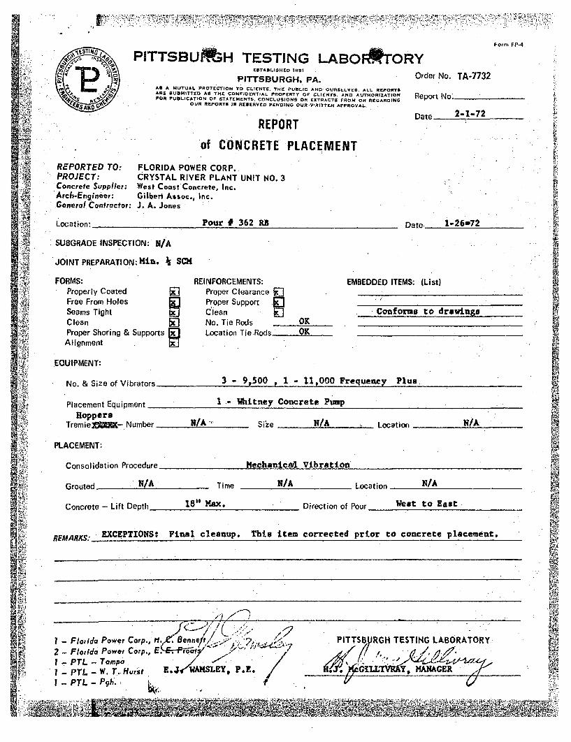
REPORTED TO: FLORIDA POWER CORP.X PROJECT: CRYSTAL RIVER PLANT UNIT NO. 3
Concrete Supplier: West Coast Concrete, Inc.• Arch-Engineer: Gilbert Assoc., Inc.General Contractor: J. A. Jones A
Location: Pour # 362 RB Date 1-26-72
.:-Z SUBGRADE INSPECTION: N/A
JOINT PREPARATION: Ki. 7, SCH $
FORMS: REINFORCEMENTS: EMBEDDED ITEMS: (List)Properly Coated [] Proper Clearance __
Free From Holes jJ Proper Support ."
Seams Tight Cflean Conforms to drawingsClean No. Tie Rods OKProper Shoring & Supports jJ Location Tie.Rods OKAlignment[]
EQUIPMENT:
No. & Size of Vibrators 3- 91500 P 1 - 11,000 Frequency Plus,
Placement Equipment 1 - Witney Concrete PumpHoppers
TremieX•= -Number N/A - Size N/A Location N/A
PLACEMENT:
Consolidation Procedure Sechanical Vibration
NIAGrouted Time N/A Location N/A
18", ma.Ws" oEsConcrete - Lift Depth 18" ' Direction of Pour West to East
EXCEPTIONS: Final cleanup. This item corrected prior to concrete placement.REMARKS:
Corp., H..,' B'
1 -Florida Power Corp., fl.,•,Benne/t.<':. ., PITTSBUYRHTESTING LABORATORY
2 - Florida Power Corp., E. ro tI PTL- Tampa , , '", //.I -PTL - W. TI. Hurst E. WAMSLEY, P.E G1' Y_______________
I PTL -Pgh.:
Rv 01

,-,,, 7,,7
Form FP-4
P I PITTS BU H TESTING LABO ORYn ESTABLISHED 1881 A
PITTSBURGH, PA. Order No. TA-7732• As A MUTUAL PROTECTION TO CLIENTS. THE PUBLIC AND OURSELVES. ALL REPORTS
ARE UBOMITTED AS THE CONFIDENTIAL PROPERTY OF CLIENTE. AND AUTHORIZATION Report No; _ _
!4, . .FOR PUBLICATION OF STATEMENTS, CONCLUSIONS OR EXTRACTS FROM OR REGARDINGOUR REPORTS IS RESERVED PENDING OUR-'WRITTEN APPROVAL. . De 1•:• . ~ ~Date: 2-1-72... . ,
• .. REPORT
of CONCRETE PLACEMENT
REPORTED TO: FLORIDA POWER CORP..PROJECT: CRYSTAL RIVER PLANT UNIT NO. 3Concrete Supplier: West Coast Concrete, Inc.Arch-Engineer: Gilbert Assoc., Inc.General Contractor: J. A. JonesLocation: ]Pour # 362 RB Date 1-26-72
SUBGRADE INSPECTION: N/AJOINT PREPARATION:.Hin SCH
FORMS: REINFORCEMENTS: EMBEDDED ITEMS: (List)Properly Coated Proper Clearance [ '.Free From Holes jJ Proper Support -0"Seams Tight Clean Conforms to drawings-Clean No. Tie Rods OKProper Shoring & Supports 01 Location Tie.Rods OK -
- Alignment
EGUIPMENT;
No. & Size of Vibrators 3- 9t500 1 1 - 11,000 Frequency Plus.
Placement Equipment -I -Whitney Concrete Pump
HoppersTremiejC=- Number N/A Size N/A Location N/A
PLACEMENT:
Consolidation Procedure Mechanicer Vibration
Grouted . Time N/A Location N/A
Concrete - Lift Depth 18" HSX. Direction of Pour l to East
EXCEPTIONS: Final cleanup. This item corrected prior to concrete placement.REMARKS: ECPIN I ,
FloridaPower Corp., H,,,Benne ,.", PITTSBURGH TESTING LABORATORY:
• 2 - F lo rid a P o w e r C o rp ., E . "• ..: l • o fI/. , , /
I - PTL - W. T. Hurst E. WAHSLEY, I• .. GlMA
I - PTL - Pgh.

PITTSBURGH "" rSTING LABORATORYPITTSBUJRGH, PA. 0rc
AU A .&Y'!.JAL PPOTtCTION TO Ct ?ENT%~. TF PIJOILJC ANDO 0U9~.ILVt$. ALL REPIOMTAR VIJSMIYItD AN THE CONFIDENTIAL PPOP94TY OF CL:CN!S. ANDO AUJTMOMIZAlioft RFOR PVIjULCATiON Or :TAT IMENITS. CONdCLUSIONS 00 IN1TRACT8 PROM Oft *NSA"ON "'a
OUR REPO 16 IP RESERVED PINDING OUIN WRITTEN APPROVAL
REPU1TDe
Form FP-4
der No. TA-7732
ort No.
te 7-21-72
of CONCRETE PLACEMENT
REPORTED TO:PROJECT:Concrete Supplier:Are&.Engi,,.er:General Contractor:
FLORIDA POWER CORP.CRYSTAL RIVER PLANT UNIT NO. 3West Coast Concrete, Inc.Gilbert Assoc., Inc.J. A. Jones
Pour # 32., 7.BI - Date -25 July 72Otton:
SUBORADE INSPECTION: IT/A
JOINT PREPARATION: C
FORMS:Properly CoatedFree Fro,-- Hoies
Seams T"hntCleanProper Shoring & SupportsAlignment
REINFORCEMENTS:Procer CearanceProDer Support r-1Clean 1ZNo. Tie Rods 0_ _
Location Tie Rods_ __ _
EMBEDDED ITEMS: (L ist)<
Cor~for-s- to davn
EQUIPMENT:
A
No. & Size of Vibrators 6 - 10,511 Frequency Plus
2 - 6" Wittney Conc~rete PuiipusPlacement Equipment
Tremie Pipes - Number NI Size NIA _ .Location K/A
L. PLACEMENT:
Consolidation Procedure Mpcý-arllcll V:!ýZaýýior -
Grouted N/A Time NIA Location NiA
Concrete - Lift Depth !311 ma( Direction of Pour 30'j. to N.E.
REMMKS: -EXCT -71NS: F'nal clean-.:, reno---vl c-f excess vate-. Bot~h Etemes car~rctod ?rt?
to placermwnt of comcretr.
I - Floride Pewet Coo. i4he .4v~' x I
I - Flordao Power Ca'r-' E. It, Proof sI -PTL -Tampa / I
I - PmL - F-0.
PITTSIURGKt TES;TIN4 LAGORATORY
.Ji.J. KcCILLIVRAY, KWAf."tl
4
q
P1TTZZURZGH TESTING LA23ORATORY£DTAB-IWHrD T001
Ort._PITTSBURGH, PA,.._0
AID A MUTUAL PROTECTION TO CLI ENT5. THE PUSLI C AND OURSELVES. ALL REPORTSARE OU:MITTEO AS THE CONFIDZNTIAL PROPERTY OF CL.F ENT&. AND AUTHORIZATION " ReFOR PU LICATION OF .TATiM•EHTS, CONCLUIiON5 OR EXFIACOVS FROM OR RtGAROINO
OUR REPORT IS R1RESERVED PENDINO OUR V'RITTEN APPROVAL,
REPORT Da
Form FP-4
der No. TA-7732
port No._ _ __
te
of CO1MCFETE PLACEMIENT
REPORTED TO:PROJECT:Concreta Supplier:Arch-Engineer:General Contractor:
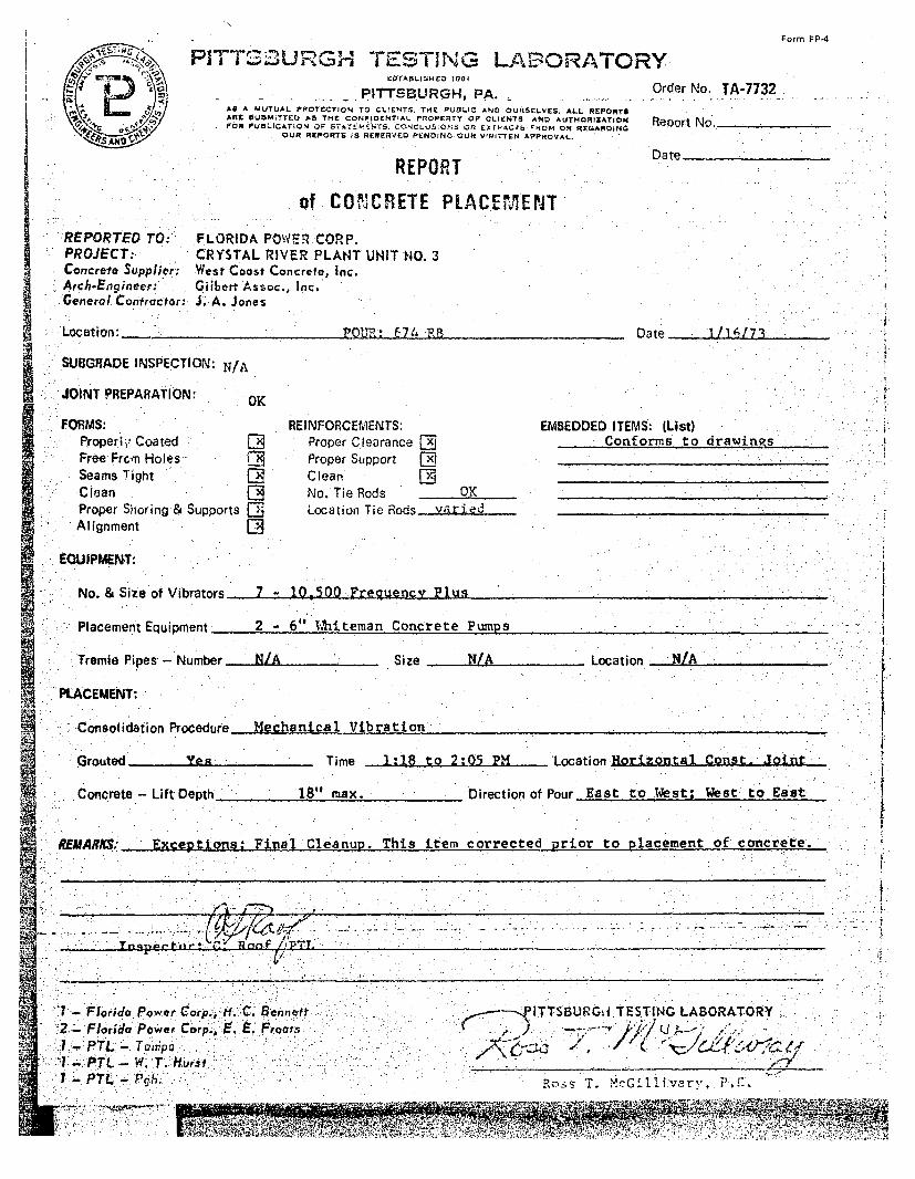
FLORIDA POWER CORP.CRYSTAL RIVER PLANT UNIT NO. 3West Coast Concrete, Inc.Giibert, Assoc., Inc.J. A. Jones
Location: 'P01• M 714 'RR Date 111617',
SUBGRADE INSPECTION: N/A
JOINT PREPARATION: OK
FORMS:Properiy CoatedFree Frcrn HolesSeams TightCleanProper Shoring& SupportsAlignment
REINFORCEMENTS:Proper Clearance FRProper Support CEClean INNo. Tie Rods OK
Location Tie Rods varied
EMBEDDED ITEMS: (List)Conforms to drawings
EQUIPMENT:
No. & Size of Vibrators
Placement Equipment
7 - 10500 Frequency Plus
2 - 6" hIAteman Concrete Pumps
Tremie Pipes - Number N/A Size N/A Location NIA ,,
PLACEMENT:
Consolidation Procedure Mechanical Vibration
,, , i
Grouted Yen Time 1:18 to 2:05 PM Location Horizontal Const. Joint
West to EastConcrete - Lift Depth 18" max. Direction of Pour East to West;
RFMARKM Vve-nt~fnna Final ýCleantin Thlis item corrected nrior to placement oficoncrete I
-.. -- - - *.... ..-.-. ~ Iv 4: nrý T
.............
'1-FhoridoTPower C'orP., i.'C. aennett
2- FlOrida Power C orp.: E..E. Froaiý s1.-.PTL. Twnpr.
j: PtL- 'T.TJHvir"I -PTrL - flh.'
<------.PITTSBURG•i TESTING LABORATORY
Ross T. MczG1ll.1tvary, P.F.
A'" '1 11, Mll g
" a P ý "''ý '4190 1
dffi mtý'$r 4-'nw. I ý 1, 'ý -,,1_11,"I"', ,,011. -N" I NO

* .3: ~ - ~ -5,
Fafrn, FP-4
PITTSBURGH TESTING LABORATORY
PITTSBURGH. PA-OdfNo A73AS A M4UTUAL PRýrrrCT?0o TO CL)FPNTS. V.C P.j&I'C A% OIJPSELV'ES. ALL xcraorsA. E a Ub:;fCO All T.'( CONrtOEHTIAL O905TRI OF Cý. ENS AVZ) &tTHORt2ITIO.4F P~LIC&ION OF SATEXrT FM-. CONCLUS.OF-S OR EXF4I FROM OR RtGAR~iNG,
OUR REPOPMT 13 Ktu KVCD PIKOING OýýA "*rrrtI- APPPOIVA4.
REPORT
of CONCRETE PLACEMENT
REPORTED TO: FLORIDA POWER CORP.PROJECT. CRYSTAL RIVER PLANT UNIT NO. 3Concrete Supplier. West Cioost Concret, Inc.Arch-Engineer: Gilbert Assoc., Inc."Generol Contractor: J. A. jones
InspectorC. zý5Ol PT
'Lod, tio:- ' : :,. .. " '. .- O T ".7 -- FOUR. .P -3te,-'UBGRADE INSPECT"I' : .N : . . . , . .- . '. - " .... . -
OI. P R ION: O -.. .......... ............... ."...
JOINT PREPARATION: OK {!
FORMS:Properly CoatedFree Fro'm HolesSeams TightCleanProper Shoring &Alignment
Supports ED~I
FiEINFORCEMENTS:Proper Clearance 17Proper Support oxClean ".No. Tie Rods 0LKLocation Tie Rods Var-i Pri
EMBEDDED ITEMS: (List)eonfor~e d to 6_r avdin •s('anform-.d to d-Aydnc-s
EQUiPMENT:
No. & Size of V.ibrators 5 -10,500 and 1 - 12,500 Freaousncy Plus
Placement Equi pmernt 2 - 6:1 %h-i tecrian Concrete Pum.ps
Tremie Pipes - Number NA _ size NA -Location NA
PLACEMMIT:
Consolidation Procedinre 4echran~ical Vibration
Grouted Yes Time 11:15 AM - 12:20 FIM Location Hor. Const. Jt.
Concrete - Lift Depth_ 18' Direction of Pour E to N; W to E
REM~ARKS:- BxcptiLons: None
CC: 2 -FPC Qu~alidty Recards
3- F T L_BTSTBURGH TMITNG LABORATORY
Ross T. VGLlvaP
ATT.AC1MIJNENT. C"u.2
ERLIN, HIME ASSOCIATES
MATERIALS AND CONCRETE CONSULTANTS
-tI *KI BOULEVARD 1312) 272.7730
,. l'• ILLINOIS 60062 /
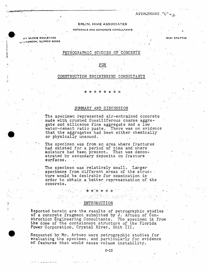
PETROGRAPHIC STUDIES OF CONCRETE
FOR
CONSTRUCTION ENGINEERING CONSULTANTS
SUMMARY AND DISCUSSION
*The specimen represented air-entrained concrete.made with crushed fossiliferous coarse aggre-gate and'siliceous fine aggregate and a lowwater-cement ratio paste. There was no evidencethat the aggregates had been either chemicallyor physically unsound.
The specimen was from an area where fractureshad existed for a period of time and wheremoisture had been present. That was demon-strated by secondary deposits on fracturesurfaces.
The specimen was relatively small. Largerspecimens fr.om different areas of the struc-ture would be desirable for examination inorder to obtain a better representation of theconcrete.
INTRODUCTION
Reported herein are the results of petrographic studiesof a concrete fragment submitted by J. Artuso of Con-struction Engineering Consultants. The specimen is fromthe dome of the containment structure of the FloridaPower Corporation,'Crystal River, Unit III.
Requested by Mr. Artuso were petrographic studies forevaluating the specimen, and particularly for evidenceof features that would cause volume instability.
C-12
I
ERLIN, HIME ASSOCIATES - MATERIALS AND CONCRETE CONSULTANTS
STUDIES
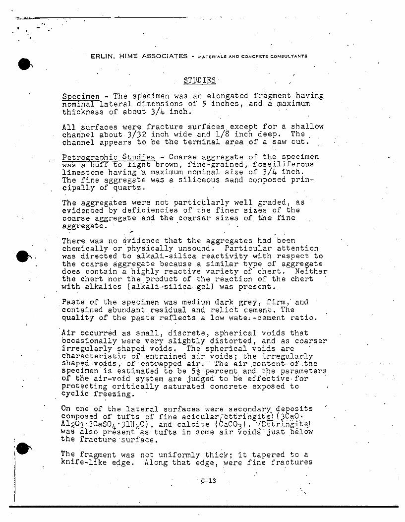
Specimen - The sp~ecimen was an elongated fragment havingnominal lateral dimensions of 5 inches, and a maximumthickness of about 3/4 inch.
All surfaces were fracture surfaces except for a shallowchannel about 3/32 inch wide and 1/8 inch deep. Thechannel appears to be the terminal area of a saw cut.
Petrographic Studies - Coarse aggregate of the specimenwas a buff to light brown, fine-grained, fossiliferouslimestone having a maximum nominal size of 3/4 inch.The fine aggregate was a siliceous sand composed prin-cipally of quartz.
The aggregates were not particdiarly well graded, asevidenced by deficiencies of the finer sizes of thecoarse aggregate and the coarser sizes of the fineaggregate.
There was no evidence that the aggregates had beenchemically or physically unsound. Particular attentionwas directed to alkali-silica reactivity with respect tothe coarse aggregate because a similar type of aggregatedoes contain a highly reactive variety of chert. Neitherthe chert nor the product of the reaction of the chertwith alkalies (alkali-silica gel) was present.
Paste of the specirhen was medium dark grey', firm, andcontained abundant residual and relict cement. Thequality of the paste reflects a low watei-cement ratio.
Air occurred as small, discrete, spherical voids thatbccasionally were very slightly distorted, and as coarserirregularly shaped voids. The spherical voids arecharacteristic of entrained air voids; the irregularlyshaped voids,: of entrapped air., The air content of :thespecimen is estimated to be 52 percent and the parametersof the air-void system are judged to be effective forprotecting critically saturated concrete exposed tocyclic freezing.
On one of the lateral surfaces were secondary depositscomposed of tufts of fine aciculari-ttringit (3CaO.A20"3CaSO4 "31H 2 0), and calcite (6TCa 3 ) •Ettringite)was also present as tufts in some air void sjust belowthe fracture-surface.
The fragment was not uniformly thick; it tapered to aknife-like edge. Along that edge, were fine fractures
' c-13
ERLIN, HIME ASSOCIATES - MATERIALS AND CONCRETE CONSULTANTS
oriented subparallel to the long axis of the fragment.The fractures transected coarse aggregate particles. Onthose fracture s-urfaces were secondary deposits similarto those described above.
The secondary compounds demonstrate that the fragmentwas from an area where fractures present for a periodof time had been exposed to moisture.
.May 10, 1976 Erlin, Hime Associates, Inc.
by Bernard Erlin, PresidentPetrographer
O"
c-14

0 0DIRECT TENSILE STRENGTH TEST RESULTS
AREA -,SO. TN.
NOMINALDIAMETER
TN.
TOTALLOADLBS.-•WV P.S.I- REMARKS
Granite aggregate -8.19 3 1/4 3400 415concrete
5000 p.s.i. value ......8.14 3 1/4 3200 390
Crystal River Cores Average 400 p.s.i.
-Pr 10.69 3 3/4 2500 230 All CoarseN Pour XVI
__aggregate soft
M.Pour XVIII 1-0.69 3 3/4 4600 430 Hard Coarseaggregate excepu.two soft pieces
L Pour XV 10.69 3 3/4 5400 505 All hard coarseaggregate
L Pour 9B 10.69 3 3/4 5400 485 Most coarseaggregate hard
P Pour XIII 10.69 3 3/4 5400 505 All hard coarseaggregate
Pour XII :10.63 3 3/4 3800 3W All small soft
_ _ coarse aggregate-Average 420 p.s.i.
Ln
kote: The Granite Aggregate concrete cores fractured surfaces indicated all coarse aggregatewas hard and dense and several pieces of the CA pulled out of the Matrix, indicatinggreater tensile strength than the Matrix. There was no pull out of the Crystal Rivercoarse aggregate - all fractured at the fractured surface.
C?
Ct
tj

ATTACHMENT E
Preliminary Report ofCrystal River Coarse Aggregate
Sieve
1
3/4
1/2
3/8
4
8
Pan
Wgt. Ret.
0
1.0
15.8
28.4
35.8
36.3
37.3
% Passing
100
97
58
24
ASTM Spec# 67
100
90-100
4
3
20-55
0-10
0-5
C-117
C-131
C-123
C-29
C-142
C-235
C-88
C-127
Test
200 Wash Loss
Los Angeles Abrasion
Lightweight Pieces in Aggregate
Unit Weight of Aggregate
Friable Particles
Soft Particles
Soundness (Sodium Sulphate) "
Specific Gravity and Absorption
Result ASTM Specification
1.3% (Primarily 1% Max*dust of fracture)
42 % 50% Max
0.2% 0.5% Max
85.68 lbs/cu. ft. No Spec
Later 5.0% Max
Later 5.0% Max
Later 12.0% Max
Later No Spec
*This limit may be increased to 1.5% if the material finer than a No. 200 consistsessential of dust from fracture
C-16
Copy No. 1
Report forProgress Energy
CTLGroup Project No. 059169
.Petrographic Examination of Concrete HalfCore from Delaminated Containment Wall,Crystal River, Florida
November 2, 2009
Submitted by:
Derek Brown
COA #4731
5400 Old Orchard RoadSkokie, Illinois 60077-1030(847) 965-7500
9030 Red Branch Road, Suite 110Columbia, Maryland 21045
www.CTLGroup.com
R e s u I t s
CTI i G~oup is a~~i r dh
Building Knowledge, Delivering Results. wwwCTLGroiup.cxo
REPORT OF PETROGRAPHIC EXAMINATION
Date: November 2, 2009
CTLGroup Project No.: 059169
Petrographic Examination of Concrete Half Core from Delaminated Containment Wall,Crystal River, Florida
One saw cut half concrete core labeled Core #5 (Figs. 1 and 2) was received on October 27,
2009 from Mr. Jerzy Zemajtis, Project Manager, CTLGroup on behalf of Mr. Paul Fagan of
Progress Energy, Crystal River, Florida. According to Mr. Zemajtis, the core represents the
outer portion of concrete from a containment wall and the core is fractured at its inner surface at
a delamination that was found to be present when access was gained to the wall interior. The
delamination is approximately at a depth of 200 mm (8.0 in.) where horizontal post tensioning
ducts are present.
Petrographic examination (ASTM C856-04) of the core was requested in order to determine, if
possible, if the delamination is a recent feature, or alternatively if it occurred at some earlier time
in the age of the structure.
FINDINGS AND CONCLUSIONS
The following findings result from the petrographic examination.
Based on the general appearance, and both the physical and microstructural properties, the
fracture at the point of delamination is most likely a fairly recent event. However, it is not
possible to be completely definitive about the time frame since an older fracture, if subsequently
well protected from air and moisture ingress, may also have similar characteristics.
The fracture surface passes through, not around the aggregates particles, is moderately hard,
and does not exhibit loose surface debris. There is an absence of significant microcracking in
the general vicinity of the fracture, and only limited evidence of surface deposits (slight
efflorescence).
Cerp;,tu Offic oi 54100 Oid (Oichwd R(oad Skokie, linois 60077-1030. Phon e: 347-965-7500 Fmx: 847-96,5-6541
Wastih~h~iS DC Ofiea: 9030 Fted 1l3iaich Road, Suite 110 Co lm~bia Maryland 21045-2003 Phone: 410-997-0400 Fax: 410-997-8480
C'ILGrorup is aoregistered iib/a of Consiructiop 7"ethnoloy, Laborawories. Inc.
Progress Energy Page 2 of 10Crystal River November 2, 2009CTLGroup Project No. 059169
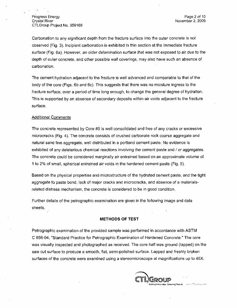
Carbonation to any significant depth from the fracture surface into the outer concrete is not
observed (Fig. 3). Incipient carbonation is exhibited in thin section at the immediate fracture
surface (Fig. 6a). However, an older delamination surface that was not exposed to air due to the
depth of outer concrete, and other possible wall coverings, may also have such an absence of
carbonation.
The cement hydration adjacent to the fracture is well advanced and comparable to that of the
body of the core (Figs. 6b and 6c). This suggests that there was no moisture ingress to the
fracture surface, over a period of time long enough, to change the general degree of hydration.
This is supported by an absence of secondary deposits within air voids adjacent to the fracture
surface.
Additional Comments
The concrete represented by Core #5 is well consolidated and free of any cracks or excessive
microcracks (Fig. 4). The concrete consists of crushed carbonate rock coarse aggregate and
natural sand fine aggregate, well distributed in a portland cement paste. No evidence is
exhibited of any deleterious chemical reactions involving the cement paste and / or aggregates.
The concrete could be considered marginally air entrained based on an approximate volume of
1 to 2% of small, spherical entrained air voids in the hardened cement paste (Fig. 5).
Based on the physical properties and microstructure of the hydrated cement paste, and the tight
aggregate to paste bond, lack of major cracks and microcracks, and absence of a materials-
related distress mechanism, the concrete is considered to be in good condition.
Further details of the petrographic examination are given in the following image and data
sheets.
METHODS OF TEST
Petrographic examination of the provided sample was performed in accordance with ASTM
C 856-04, "Standard Practice for Petrographic Examination of Hardened Concrete." The core
was visually inspected and photographed as received. The core half was ground (lapped) on the
saw cut surface to produce a smooth, flat, semi-polished surface. Lapped and freshly broken
surfaces of the concrete were examined using a stereomicroscope at magnifications up to 45X.
Progress Energy Page 3 of 10Crystal River November 2, 2009CTLGroup Project No. 059169
For thin-section study, small rectangular blocks were cut from the core inner surface fracture
region and within the body of the core. One side of each block was lapped to produce a smooth,
flat surface. The blocks were cleaned and dried, and the prepared surfaces mounted on
separate ground glass microscope slides with epoxy resin. After the epoxy hardened, the
thickness of the mounted blocks was reduced to approximately 20 ptm (0.0008 in.). The resulting
thin sections were examined using a polarized-light (petrographic) microscope at magnifications
up to 400X to study aggregate and paste mineralogy and microstructure.
Estimated water-cement ratio (w/c), when reported, is based on observed concrete and paste
properties including, but not limited to: 1) relative amounts of residual (unhydrated and partially
hydrated) portland cement clinker particles, 2) amount and size of calcium hydroxide crystals,
3) paste hardness, color, and luster, 4) paste-aggregate bond, and 5) relative absorbency of
paste as indicated by the readiness of a freshly fractured surface to absorb applied water
droplets. These techniques have been widely used by industry professionals to estimate w/c.
Depth and pattern of paste carbonation was initially determined by application of a pH indicator
solution (phenolphthalein) to freshly cut and original fractured concrete surfaces. The solution
imparts a deep magenta stain to high pH, non-carbonated paste. Carbonated paste does not
change color. The extent of paste carbonation was confirmed in thin-section.
Derek BrownSenior MicroscopistMicroscopy Group
DB/DB
Notes: 1. Results refer specifically to the sample submitted.2. This report may not be reproduced except in its entirety.3. The sample will be retained for 30 days, after which it will be discarded unless we hear
otherwise from you.
Middij g Knn.vte~dqP Dr.1wricng Re-s ý vwA.,' Go i0 :_

Progress EnergyCrystal RiverCTLGroup Project No. 059169
Page 4 of 10November 2, 2009
la. Curved surface. Outer end is to the left.
lb. Saw cut surface. Outer end is to the left
Fig. 1 Side views of Core #5, as received for examination.
T"'GROUPMAJ"d~ Knewk-dqo OeAh#.vN RwwI!s

Progress EnergyCrystal RiverCTLGroup Project No. 059169
Page 5 of 10November 2, 2009
2a. Inner end.
2b. Outer end.
Fig. 2 End views of Core #5, as received for examination.
G"ICROUP
Progress EnergyCrystal RiverCTLGroup Project No. 059169
Page 6 of 10November 2, 2009
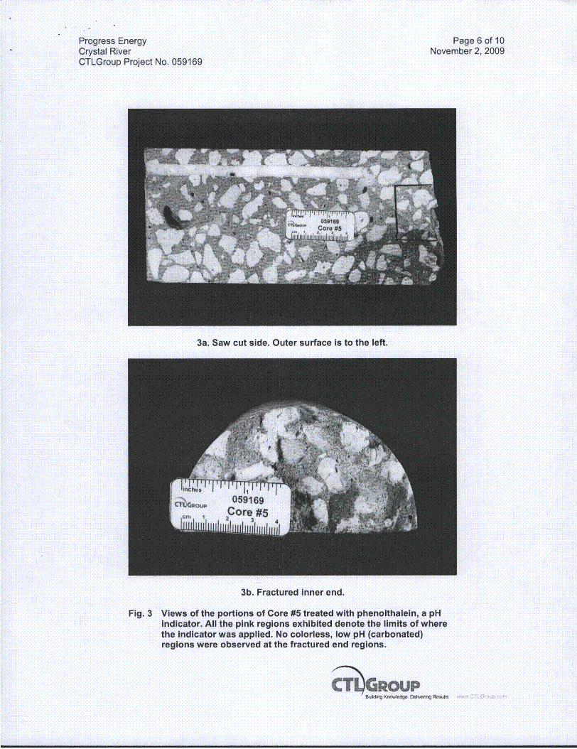
3a. Saw cut side. Outer surface is to the left.
3b. Fractured inner end.
Fig. 3 Views of the portions of Core #5 treated with phenolthalein, a pHIndicator. All the pink regions exhibited denote the limits of wherethe Indicator was applied. No colorless, low pH (carbonated)regions were observed at the fractured end regions.
1nC*1q " DMomg Rest*%~

Progress EnergyCrystal RiverCTLGroup Project No. 059169
Page 7 of 10November 2, 2009
Fig. 4 View of the lapped surface of a portion of Core #5 showing thegeneral appearance of the concrete.
Fig. 5 View of the concrete hardened air-void system of Core #5illustrating the moderate quantity of both coarse and fine air voids.Scale is millimeter Increments.
GROPBul'dýq h onwMd ~vln Rmuft

Progress Energy Page 8 of 10Crystal River November 2, 2009CTLGroup Project No. 059169
6a. Crossed-polarized lightview of the paste adjacentto the inner fracturedsurface. Only Incipientcarbonation is Indicated bythe speckled highbirefringence colors in thepaste. Carbonate fines arearrowed yellow. Width ofview is approximately0.5 mm.
6b. Plane-polarized light viewof the paste adjacent to theinner fractured surface
(same field of view as 6a.).A low to moderate numberof unhydrated and partiallyhydrated cement particles(arrowed red) are exhibitedby the paste. The amountis comparable to that inthe body of the core in Fig.6c. below. Width of view isapproximately 0.5 mm.
6c. Plane-polarized light viewof the paste in the body ofthe core. A low tomoderate number ofunhydrated and partiallyhydrated cement particles
4(arrowed red) are exhibitedby the paste. The amountis comparable to that nearthe fracture surface In Fig.6b. above Width of view isapproximately 0.5 mm.
Fig. 6 Transmitted light photomicrographs of the thin sections of Core #5 illustrating significantfeatures,
T IGROUP

Progress Energy Page 9 of 10Crystal River November 2, 2009CTLGroup Project No. 059169
PETROGRAPHIC EXAMINATION OF HARDENED CONCRETE, ASTM C 856
STRUCTURE: Containment wall DATE RECEIVED: October 27, 2009
LOCATION: Crystal River EXAMINED BY: Derek Brown
SAMPLE
Client Identification: Core #5.
CTLGroup Identification: 2452601.
Dimensions: Core diameter = 95 mm (3.75 in.). Core length = approximately 197 mm (7.75in.); partial wall thickness.
Top End: Even, slightly rough formed surface.
Bottom End: Uneven and rough, fractured core end.
Cracks, Joints, Large Voids: Text.
Reinforcement: None observed in the core supplied.
AGGREGATES
Coarse: Crushed rock Composed of carbonate rock type.
Fine: Natural quartz sand.
Gradation & Top Size: Visually appears evenly graded to an observed top size of 18 mm(0.75 in.).
Shape, Texture, Distribution: Coarse- Sub rounded to angular, slightly irregular to rough,evenly distributed. Fine- Rounded to sub angular, slightly smooth to somewhat rough, evenlydistributed
PASTE
Color: Medium gray, uniform coloration throughout the length of the core.
Hardness: Moderately hard at the outer surface and in the body of the core. At the fracturesurface the paste is also moderately hard.
Luster: Subvitreous.
Paste-Aggregate Bond: Tight. Freshly fractured surfaces pass through aggregate particles.
Air Content: Estimated 2 to 4% total. Approximately 1 to 2% of the total air is largerentrapped air voids of up to 3 mm (0.12 in.) in size, plus a few large voids of 4 to 10 mm (0.16

Progress Energy Page 10 of 10Crystal River November 2, 2009CTLGroup Project No. 059169
to 0.4 in.). Somewhat uneven distribution of voids. Marginally air entrained based on the verylow volume of moderate to small sized spherical air voids in the hardened cement paste.
Depth of Carbonation: 4 to 5 mm (0.16 to 0.20 in.) as measured from the outer surface.Negligible when measured from the inner fractured core surface.
Calcium Hydroxide*: Estimated 6 to 12% of small to medium sized crystals evenlydistributed throughout the paste, and around aggregate to paste interfaces. Estimation of thevolume is difficult due to the presence of calcite fines in the cement paste.
Residual Portland Cement Clinker Particles*: Estimated 4 to 8%. Some large cementparticles, particularly belite clusters, of up to 0.15 mm in size suggest a portland cement asproduced more than 30 years ago.
Supplementary Cementitious Materials*: None observed by the core supplied.
Secondary Deposits: None observed either in the body of the core and or near the fracturesurface.
MICROCRACKING: A small number of medium length (5 to 10 mm), randomly orientatedmicrocracks are evenly distributed throughout the body of the core. At the fractured end of thecore there was no observed increase in microcracking relative to the body of the core.
ESTIMATED WATER-CEMENT RATIO: Moderate to moderately high (0.50 to 0.60) butestimation may be biased upwards due to the well advanced degree of hydration / apparent oldage of the concrete.
MISCELLANEOUS:
1. Water droplets applied to freshly fractured surfaces were somewhat slowly absorbed bythe hardened cement paste.
2. Some small areas of the inner fractured surface of the core, as received, exhibit a thinwhite haze of efflorescence-like substance suggesting leaching of lime in solution fromwithin the core, or alternatively, moisture on or flowing past the fractured surface at thedelamination position within the wall.
3. A moderate volume of fine calcite particles is present within the hardened cement paste,most likely from coarse aggregate crusher fines.
percent by volume of paste
Gaild , KnrmON1go OIving Rtlw :. "ww {2 LGt ,
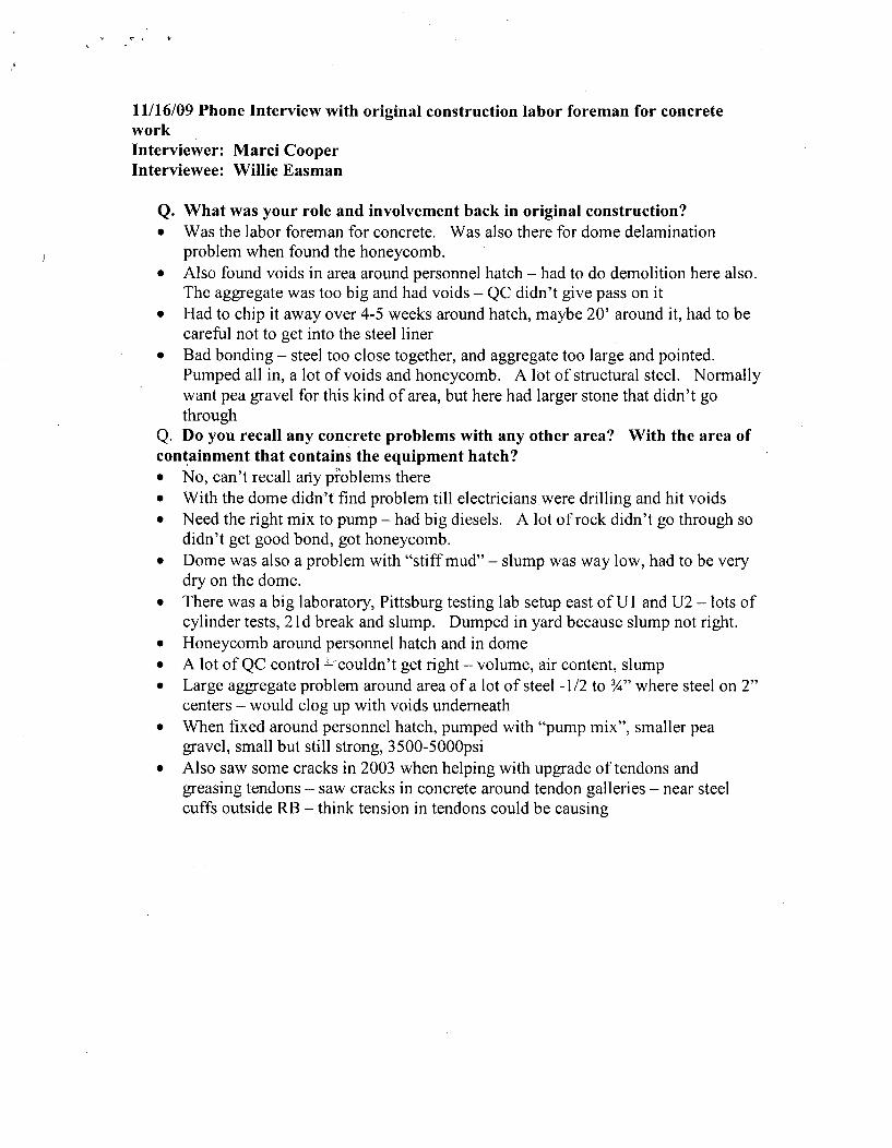
11/16/09 Phone Interview with original construction labor foreman for concreteworkInterviewer: Marci CooperInterviewee: Willie Easman
Q. What was your role and involvement back in original construction?" Was the labor foreman for concrete. Was also there for dome delamination
problem when found the honeycomb." Also found voids in area around personnel hatch - had to do demolition here also.
The aggregate was too big and had voids - QC didn't give pass on it* Had to chip it away over 4-5 weeks around hatch, maybe 20' around it, had to be
careful not to get into the steel liner" Bad bonding - steel too close together, and aggregate too large and pointed.
Pumped all in, a lot of voids and honeycomb. A lot of structural steel. Normallywant pea gravel for this kind of area, but here had larger stone that didn't gothrough
Q. Do you recall any concrete problems with any other area? With the area ofcontainment that contains the equipment hatch?* No, can't recall any pioblems there* With the dome didn't find problem till electricians.were drilling and hit voids* Need the right mix to pump - had big diesels. A lot of rock didn't go through so
didn't get good bond, got honeycomb.* Dome was also a problem with "stiff mud" - slump was way low, had to be very
dry on the dome.* There was a big laboratory, Pittsburg testing lab setup east of U I and U2 - lots of
cylinder tests, 21d break and slump. Dumped in yard because slump not right.* Honeycomb around personnel hatch and in dome* A lot of QC control L-couldn't get right - volume, air content, slump* Large aggregate problem around area of a lot of steel -1/2 to ¾" where steel on 2"
centers - would clog up with voids underneath* When fixed around personnel hatch, pumped with "pump mix", smaller pea
gravel, small but still strong, 3500-5000psio Also saw some cracks in 2003 when helping with upgrade of tendons and
greasing tendons - saw cracks in concrete around tendon galleries - near steelcuffs outside RB - think tension in tendons could be causing


![COELI DÈSUPER CopioneUnificato.pdf · 4 Nitida stella [1:00] - (Anunziata) Anonimo afff32 F =150 3 jj jj jj eii jj jj jj jj i ji j i ji j i ji j eiizz bfff32 j j j i j j j j i j](https://static.fdocuments.us/doc/165x107/5fde88e826cc8964f53d1e56/coeli-d-copioneunificatopdf-4-nitida-stella-100-anunziata-anonimo-afff32.jpg)


