EM–134 1GR-FE ENGINE MECHANICAL – ENGINE … Toyota FJ Cruiser...EM–134 1GR-FE ENGINE...
32
EM–134 1GR-FE ENGINE MECHANICAL – ENGINE UNIT EM DISASSEMBLY HINT: • Thoroughly clean all the disassembled parts before reassembly. • Before installing the parts, apply new engine oil to all sliding and rotating surfaces. • Replace all gaskets, O-rings and oil seals with new parts. 1. REMOVE ENGINE HANGERS (a) Remove the 2 bolts and No. 1 engine hanger. (b) Remove the 2 bolts and No. 2 engine hanger. 2. REMOVE ENGINE COOLANT TEMPERATURE SENSOR (a) Remove the engine coolant temperature sensor and gasket. 3. REMOVE WATER BY-PASS JOINT RR (a) Remove the 2 bolts, 4 nuts and the water by-pass rear joint. (b) Remove the 2 gaskets from the cylinder head. (c) Remove the O-ring from the outlet pipe. 4. REMOVE CAMSHAFT TIMING OIL CONTROL VALVE ASSEMBLY (for Bank 1) (a) Remove the bolt and camshaft timing oil control valve. No. 1 No. 2 A072941E02 A126460 A121043 A126464
Transcript of EM–134 1GR-FE ENGINE MECHANICAL – ENGINE … Toyota FJ Cruiser...EM–134 1GR-FE ENGINE...
EM–134 1GR-FE ENGINE MECHANICAL – ENGINE UNIT
EM
DISASSEMBLYHINT:• Thoroughly clean all the disassembled parts before
reassembly.• Before installing the parts, apply new engine oil to all
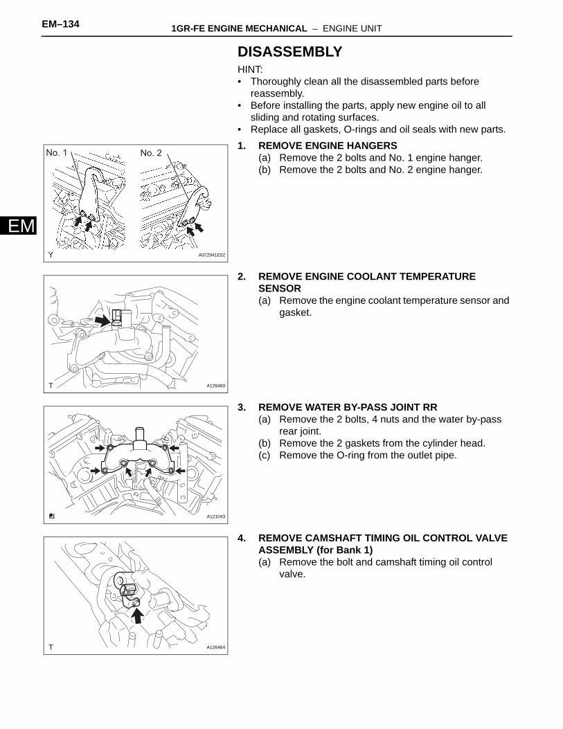
sliding and rotating surfaces.• Replace all gaskets, O-rings and oil seals with new parts.1. REMOVE ENGINE HANGERS
(a) Remove the 2 bolts and No. 1 engine hanger.(b) Remove the 2 bolts and No. 2 engine hanger.
2. REMOVE ENGINE COOLANT TEMPERATURE SENSOR(a) Remove the engine coolant temperature sensor and
gasket.
3. REMOVE WATER BY-PASS JOINT RR(a) Remove the 2 bolts, 4 nuts and the water by-pass
rear joint.(b) Remove the 2 gaskets from the cylinder head.(c) Remove the O-ring from the outlet pipe.
4. REMOVE CAMSHAFT TIMING OIL CONTROL VALVE ASSEMBLY (for Bank 1)(a) Remove the bolt and camshaft timing oil control
valve.
No. 1 No. 2
A072941E02
A126460
A121043
A126464
1GR-FE ENGINE MECHANICAL – ENGINE UNIT EM–135
M
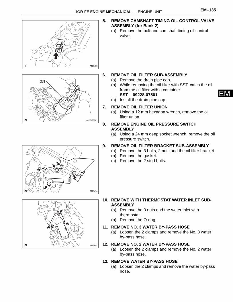
E5. REMOVE CAMSHAFT TIMING OIL CONTROL VALVE ASSEMBLY (for Bank 2)(a) Remove the bolt and camshaft timing oil control
valve.
6. REMOVE OIL FILTER SUB-ASSEMBLY(a) Remove the drain pipe cap.(b) While removing the oil filter with SST, catch the oil
from the oil filter with a container.SST 09228-07501
(c) Install the drain pipe cap.
7. REMOVE OIL FILTER UNION(a) Using a 12 mm hexagon wrench, remove the oil
filter union.
8. REMOVE ENGINE OIL PRESSURE SWITCH ASSEMBLY(a) Using a 24 mm deep socket wrench, remove the oil
pressure switch.9. REMOVE OIL FILTER BRACKET SUB-ASSEMBLY
(a) Remove the 3 bolts, 2 nuts and the oil filter bracket.(b) Remove the gasket.(c) Remove the 2 stud bolts.
10. REMOVE WITH THERMOSTAT WATER INLET SUB-ASSEMBLY(a) Remove the 3 nuts and the water inlet with
thermostat.(b) Remove the O-ring.
11. REMOVE NO. 3 WATER BY-PASS HOSE(a) Loosen the 2 clamps and remove the No. 3 water
by-pass hose.
12. REMOVE NO. 2 WATER BY-PASS HOSE(a) Loosen the 2 clamps and remove the No. 2 water
by-pass hose.
13. REMOVE WATER BY-PASS HOSE(a) Loosen the 2 clamps and remove the water by-pass
hose.
A126463
A122120E01
A120414
A121042
EM–136 1GR-FE ENGINE MECHANICAL – ENGINE UNIT
EM
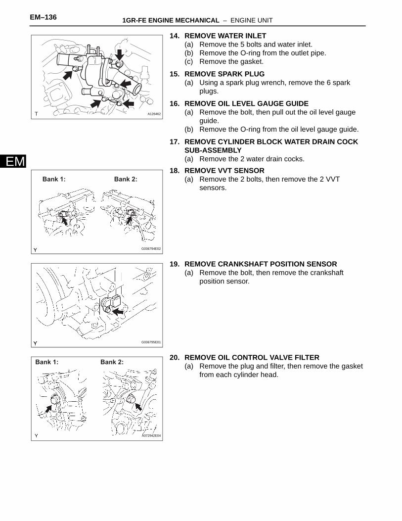
14. REMOVE WATER INLET(a) Remove the 5 bolts and water inlet.(b) Remove the O-ring from the outlet pipe.(c) Remove the gasket.
15. REMOVE SPARK PLUG(a) Using a spark plug wrench, remove the 6 spark
plugs.
16. REMOVE OIL LEVEL GAUGE GUIDE(a) Remove the bolt, then pull out the oil level gauge
guide.(b) Remove the O-ring from the oil level gauge guide.
17. REMOVE CYLINDER BLOCK WATER DRAIN COCK SUB-ASSEMBLY(a) Remove the 2 water drain cocks.
18. REMOVE VVT SENSOR(a) Remove the 2 bolts, then remove the 2 VVT
sensors.
19. REMOVE CRANKSHAFT POSITION SENSOR(a) Remove the bolt, then remove the crankshaft
position sensor.
20. REMOVE OIL CONTROL VALVE FILTER(a) Remove the plug and filter, then remove the gasket
from each cylinder head.
A126462
Bank 1: Bank 2:
G036794E02
G036795E01
Bank 2:Bank 1:
A072942E04

1GR-FE ENGINE MECHANICAL – ENGINE UNIT EM–137
M
E21. REMOVE CYLINDER HEAD COVER SUB-ASSEMBLY LH(a) Remove the 10 bolts, 3 seal washers and 2 nuts,
then remove the cylinder head cover.(b) Remove the gasket from the cylinder head cover.(c) Remove the ventilation valve from the cylinder head
cover.
22. REMOVE CYLINDER HEAD COVER SUB-ASSEMBLY(a) Remove the 10 bolts, 3 seal washers and 2 nuts,
then remove the cylinder head cover.(b) Remove the gasket from the cylinder head cover.
23. REMOVE CRANKSHAFT PULLEY(a) Turn the crankshaft pulley until its groove and the
"0" timing mark of the timing chain cover are aligned.
(b) Check that the timing marks of the camshaft timing gears are aligned with the timing marks located on the No. 1 and No. 2 bearing caps as shown in the illustration.If not, turn the crankshaft 1 complete revolution (360°) and align the timing marks as above.
A072944E01
A072943E01
A072945E01
Bank 1:
Bank 2:
Timing Marks
Timing Marks
Timing Marks
G036831E02
EM–138 1GR-FE ENGINE MECHANICAL – ENGINE UNIT
EM
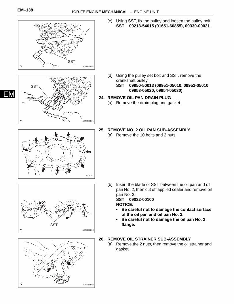
(c) Using SST, fix the pulley and loosen the pulley bolt.SST 09213-54015 (91651-60855), 09330-00021
(d) Using the pulley set bolt and SST, remove the crankshaft pulley.SST 09950-50013 (09951-05010, 09952-05010,
09953-05020, 09954-05030)24. REMOVE OIL PAN DRAIN PLUG
(a) Remove the drain plug and gasket.
25. REMOVE NO. 2 OIL PAN SUB-ASSEMBLY(a) Remove the 10 bolts and 2 nuts.
(b) Insert the blade of SST between the oil pan and oil pan No. 2, then cut off applied sealer and remove oil pan No. 2.SST 09032-00100NOTICE:• Be careful not to damage the contact surface
of the oil pan and oil pan No. 2.• Be careful not to damage the oil pan No. 2
flange.
26. REMOVE OIL STRAINER SUB-ASSEMBLY(a) Remove the 2 nuts, then remove the oil strainer and
gasket.
SSTA072947E02
SST
A072948E01
A126351
SST
A072950E02
A072951E03
1GR-FE ENGINE MECHANICAL – ENGINE UNIT EM–139
M
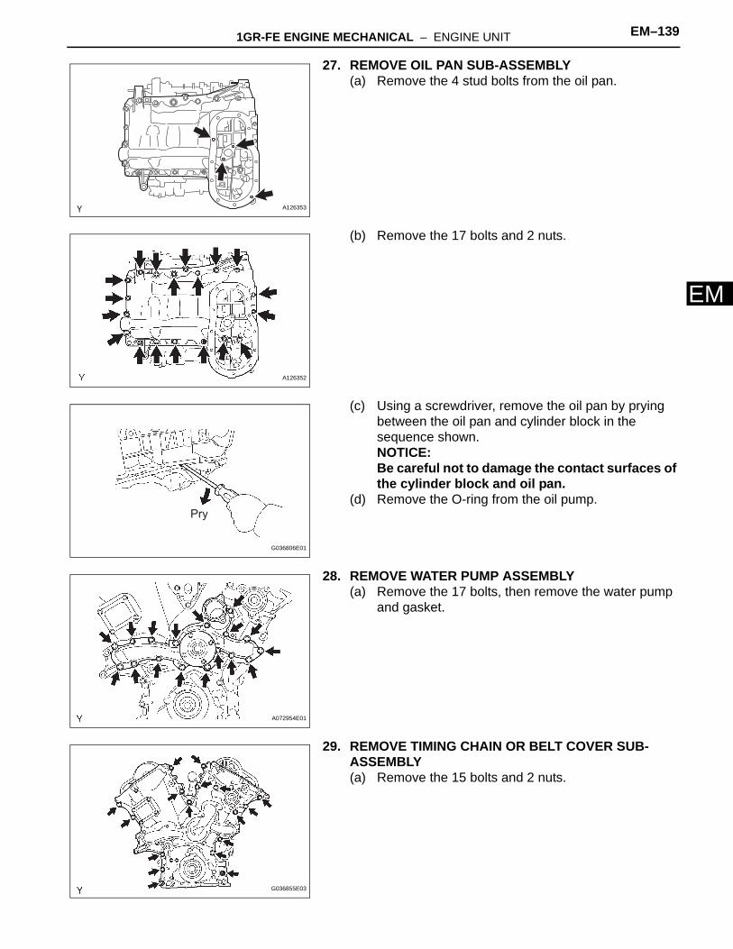
E27. REMOVE OIL PAN SUB-ASSEMBLY(a) Remove the 4 stud bolts from the oil pan.
(b) Remove the 17 bolts and 2 nuts.
(c) Using a screwdriver, remove the oil pan by prying between the oil pan and cylinder block in the sequence shown.NOTICE:Be careful not to damage the contact surfaces of the cylinder block and oil pan.
(d) Remove the O-ring from the oil pump.
28. REMOVE WATER PUMP ASSEMBLY(a) Remove the 17 bolts, then remove the water pump
and gasket.
29. REMOVE TIMING CHAIN OR BELT COVER SUB-ASSEMBLY(a) Remove the 15 bolts and 2 nuts.
Y A126353
A126352
Pry
G036806E01
A072954E01
G036855E03

EM–140 1GR-FE ENGINE MECHANICAL – ENGINE UNIT
EM
(b) Remove the timing chain cover by prying between the timing chain cover, cylinder head and cylinder block with a screwdriver.NOTICE:Be careful not to damage the contact surfaces of the timing chain cover, cylinder block and cylinder head.
(c) Remove the 4 bolts and timing chain cover plate.(d) Remove the O-ring from the cylinder head LH.
30. REMOVE NO. 1 CHAIN TENSIONER ASSEMBLYNOTICE:• Never rotate the crankshaft with the chain
tensioner removed.• When rotating the camshaft with the timing chain
removed, rotate the crankshaft counterclockwise 40° from the TDC first.
(a) While turning the stopper plate of the tensioner upward, push in the plunger of the chain tensioner as shown in the illustration.
(b) While turning the stopper plate of the tensioner downward, insert a bar of φ 3.5 mm (0.138 in.) into the holes in the stopper plate and tensioner to fix the stopper plate.
(c) Remove the 2 bolts, then remove the chain tensioner.
31. REMOVE CHAIN TENSIONER SLIPPER32. REMOVE IDLE SPROCKET ASSEMBLY
(a) Using a 10 mm hexagon wrench, remove the No. 2 idle gear shaft, No. 1 idle gear and No. 1 idle gear shaft.
33. REMOVE NO. 2 CHAIN VIBRATION DAMPER(a) Remove the 2 No. 2 chain vibration dampers.
34. REMOVE CHAIN SUB-ASSEMBLY35. REMOVE CRANKSHAFT TIMING GEAR OR
SPROCKET
G036859E01
Stopper PlateStopper Plate
Push
A072958E02
G036860E01
G036844E01
1GR-FE ENGINE MECHANICAL – ENGINE UNIT EM–141
M
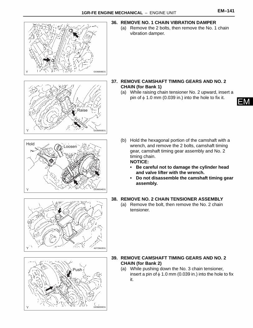
E36. REMOVE NO. 1 CHAIN VIBRATION DAMPER(a) Remove the 2 bolts, then remove the No. 1 chain
vibration damper.
37. REMOVE CAMSHAFT TIMING GEARS AND NO. 2 CHAIN (for Bank 1)(a) While raising chain tensioner No. 2 upward, insert a
pin of φ 1.0 mm (0.039 in.) into the hole to fix it.
(b) Hold the hexagonal portion of the camshaft with a wrench, and remove the 2 bolts, camshaft timing gear, camshaft timing gear assembly and No. 2 timing chain.NOTICE:• Be careful not to damage the cylinder head
and valve lifter with the wrench.• Do not disassemble the camshaft timing gear
assembly.
38. REMOVE NO. 2 CHAIN TENSIONER ASSEMBLY(a) Remove the bolt, then remove the No. 2 chain
tensioner.
39. REMOVE CAMSHAFT TIMING GEARS AND NO. 2 CHAIN (for Bank 2)(a) While pushing down the No. 3 chain tensioner,
insert a pin of φ 1.0 mm (0.039 in.) into the hole to fix it.
G036808E01
Raise
G036850E01
HoldLoosen
G036834E01
A072962E01
Push
G036835E01

EM–142 1GR-FE ENGINE MECHANICAL – ENGINE UNIT
EM
(b) Hold the hexagonal portion of the camshaft with a wrench, and remove the 2 bolts, camshaft timing gear, camshaft timing gear assembly and No. 2 timing chain.NOTICE:• Be careful not to damage the cylinder head
and valve lifter with the wrench.• Do not disassemble the camshaft timing gear
assembly.
40. REMOVE NO. 3 CHAIN TENSIONER ASSEMBLY(a) Remove the bolt, then remove the No. 3 chain
tensioner.
41. INSPECT CAMSHAFT THRUST CLEARANCE(a) Using a dial indicator, measure the thrust clearance
while moving the camshaft back and forth.Standard thrust clearance:
0.04 to 0.09 mm (0.016 to 0.035 in.)Maximum thrust clearance:
0.11 mm (0.0043 in.)If the thrust clearance is greater than the maximum, replace the camshafts.If necessary, replace the camshaft bearing caps and cylinder head as a set.
42. REMOVE CAMSHAFTSNOTICE:Keep the camshaft level while it is being removed. The camshaft thrust clearance is very small and failing to keep it level could crack or damage the cylinder head journal surface, which receives the thrust force. This could subsequently lead the camshaft to seize or break. Perform the following steps to avoid such problems.(a) Remove the camshafts of bank 1.
(1) Rotate the camshafts counterclockwise using a wrench so that cam lobes of No. 1 cylinder face in the directions as shown in the illustration.
LoosenHold
G036836E01
A072965E01
A075624E01
Bank 1:
A072966E05

1GR-FE ENGINE MECHANICAL – ENGINE UNIT EM–143
M
E(2) Using several steps, uniformly loosen and remove the 16 bearing cap bolts in the sequence shown in the illustration.
(3) Remove the 8 bearing caps, then remove the 2 camshafts.
(b) Remove the camshafts of bank 2.(1) Using several steps, uniformly loosen and
remove the 16 bearing cap bolts in the sequence shown in the illustration.
(2) Remove the 8 bearing caps, then remove the 2 camshafts.
43. REMOVE NO. 1 CAMSHAFT BEARING(a) Remove the No. 1 camshaft bearing from the No. 1
camshaft bearing cap.
44. REMOVE NO. 2 CAMSHAFT BEARING(a) Remove the No. 2 camshaft bearing from the
cylinder head for bank 1.
45. INSPECT CAMSHAFT OIL CLEARANCE(a) Clean the camshaft bearing caps, camshaft
bearings and camshaft journals.(b) Install the camshaft bearing.(c) Place the camshaft on the cylinder head.(d) Lay a strip of Plastigage across each camshaft
journal.(e) Install the camshaft bearing caps.
NOTICE:Do not turn the camshafts.
(f) Remove the camshaft bearing caps.(g) Measure the Plastigage at its widest point.
Standard oil clearance (Bank 1)
Standard oil clearance (Bank 2)
1
2
3
46
7
8
5 9
10
11
12
14
15
13
16
Bank 1:
A072967E12
3
64
7
9
8
5
2
1
10
11
12
13
14
15
16
Bank 2:
A072968E11
A076279E01
Plastigage
A075622E02
A075623E01
Camshaft Bearing Cap Specification
No. 1 (Intake) 0.008 to 0.038 mm (0.0003 to 0.0015 in.)
No. 1 (Exhaust) 0.040 to 0.079 mm (0.0016 to 0.0031 in.)
Others 0.025 to 0.062 mm (0.0010 to 0.0024 in.)
Camshaft Bearing Cap Specification
No. 1 0.040 to 0.079 mm (0.0016 to 0.0031 in.)
EM–144 1GR-FE ENGINE MECHANICAL – ENGINE UNIT
EM
Maximum oil clearance (Bank 1)
Maximum oil clearance (Bank 2):0.10 mm (0.0039 in.)
If the oil clearance is greater than the maximum, replace the camshaft bearings and/or camshafts.If necessary, replace the camshaft bearing caps and cylinder head together.Reference
(h) Remove the Plastigage completely.(i) Remove the camshafts.(j) Remove the camshaft bearing.
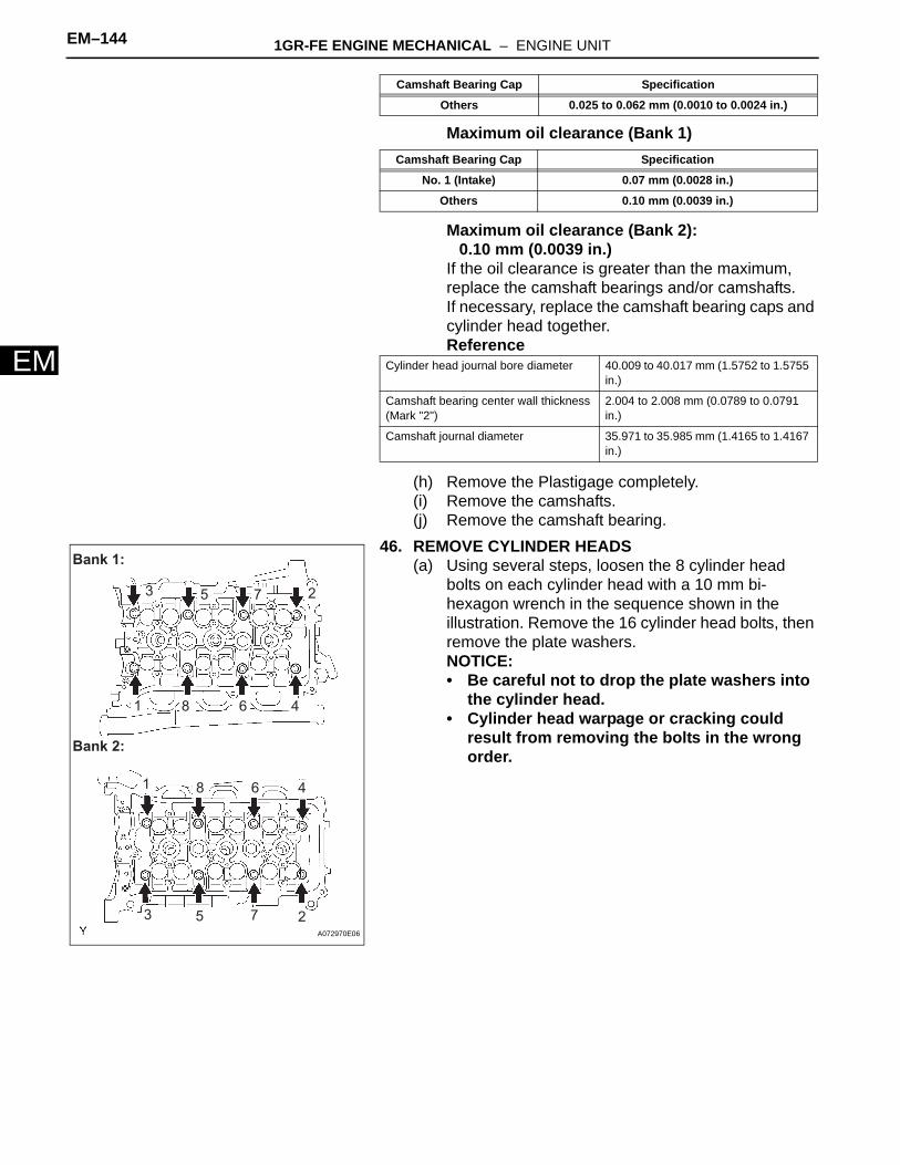
46. REMOVE CYLINDER HEADS(a) Using several steps, loosen the 8 cylinder head
bolts on each cylinder head with a 10 mm bi-hexagon wrench in the sequence shown in the illustration. Remove the 16 cylinder head bolts, then remove the plate washers.NOTICE:• Be careful not to drop the plate washers into
the cylinder head.• Cylinder head warpage or cracking could
result from removing the bolts in the wrong order.
Others 0.025 to 0.062 mm (0.0010 to 0.0024 in.)
Camshaft Bearing Cap Specification
No. 1 (Intake) 0.07 mm (0.0028 in.)
Others 0.10 mm (0.0039 in.)
Cylinder head journal bore diameter 40.009 to 40.017 mm (1.5752 to 1.5755 in.)
Camshaft bearing center wall thickness (Mark "2")
2.004 to 2.008 mm (0.0789 to 0.0791 in.)
Camshaft journal diameter 35.971 to 35.985 mm (1.4165 to 1.4167 in.)
Camshaft Bearing Cap Specification
1
3 5 27
6 4
1
8
8
25
46
73
Bank 1:
Bank 2:
A072970E06
1GR-FE ENGINE MECHANICAL – ENGINE UNIT EM–145
M
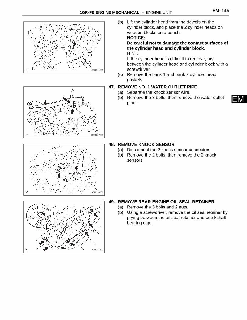
E(b) Lift the cylinder head from the dowels on the cylinder block, and place the 2 cylinder heads on wooden blocks on a bench.NOTICE:Be careful not to damage the contact surfaces of the cylinder head and cylinder block.HINT:If the cylinder head is difficult to remove, pry between the cylinder head and cylinder block with a screwdriver.
(c) Remove the bank 1 and bank 2 cylinder head gaskets.
47. REMOVE NO. 1 WATER OUTLET PIPE(a) Separate the knock sensor wire.(b) Remove the 3 bolts, then remove the water outlet
pipe.
48. REMOVE KNOCK SENSOR(a) Disconnect the 2 knock sensor connectors.(b) Remove the 2 bolts, then remove the 2 knock
sensors.
49. REMOVE REAR ENGINE OIL SEAL RETAINER(a) Remove the 5 bolts and 2 nuts.(b) Using a screwdriver, remove the oil seal retainer by
prying between the oil seal retainer and crankshaft bearing cap.
A072971E01
G036807E01
A076270E01
Pry
A076247E02
EM–146 1GR-FE ENGINE MECHANICAL – ENGINE UNIT
EM
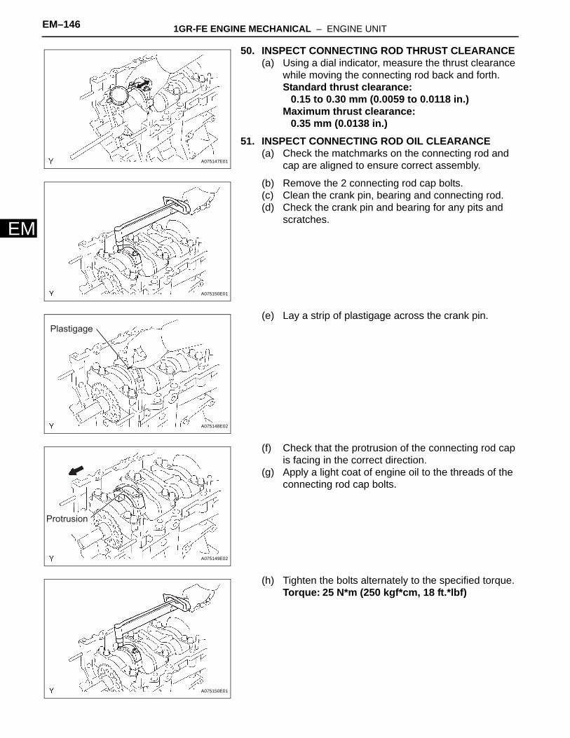
50. INSPECT CONNECTING ROD THRUST CLEARANCE(a) Using a dial indicator, measure the thrust clearance
while moving the connecting rod back and forth.Standard thrust clearance:
0.15 to 0.30 mm (0.0059 to 0.0118 in.)Maximum thrust clearance:
0.35 mm (0.0138 in.)51. INSPECT CONNECTING ROD OIL CLEARANCE
(a) Check the matchmarks on the connecting rod and cap are aligned to ensure correct assembly.
(b) Remove the 2 connecting rod cap bolts.(c) Clean the crank pin, bearing and connecting rod.(d) Check the crank pin and bearing for any pits and
scratches.
(e) Lay a strip of plastigage across the crank pin.
(f) Check that the protrusion of the connecting rod cap is facing in the correct direction.
(g) Apply a light coat of engine oil to the threads of the connecting rod cap bolts.
(h) Tighten the bolts alternately to the specified torque.Torque: 25 N*m (250 kgf*cm, 18 ft.*lbf)
A075147E01
A075150E01
Plastigage
A075148E02
Protrusion
A075149E02
A075150E01
1GR-FE ENGINE MECHANICAL – ENGINE UNIT EM–147
M
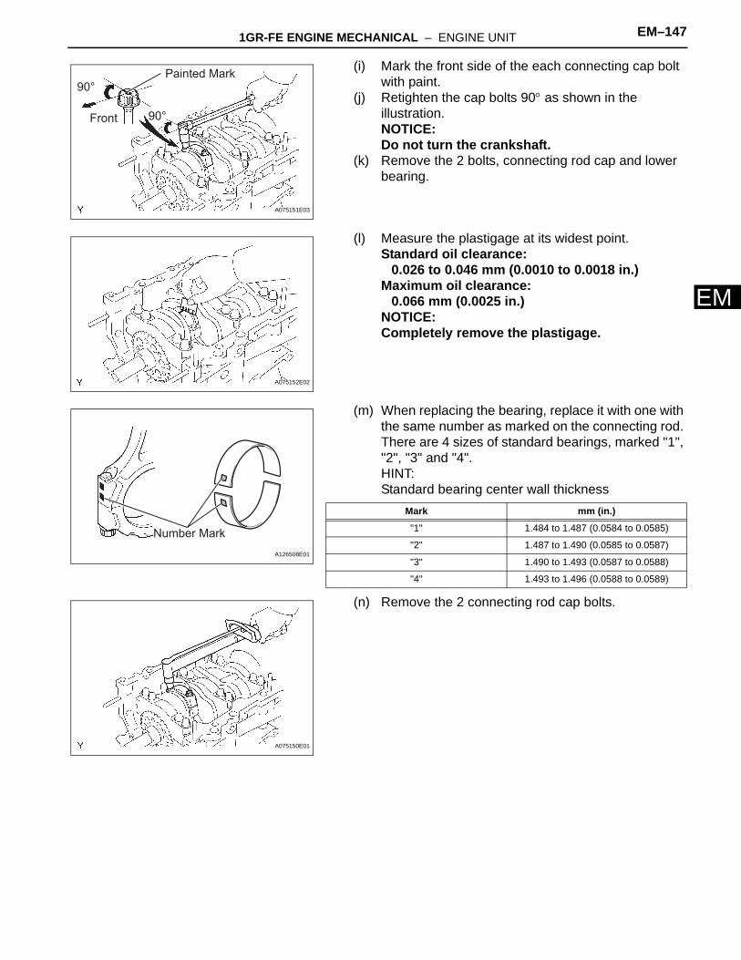
E(i) Mark the front side of the each connecting cap bolt with paint.
(j) Retighten the cap bolts 90° as shown in the illustration.NOTICE:Do not turn the crankshaft.
(k) Remove the 2 bolts, connecting rod cap and lower bearing.
(l) Measure the plastigage at its widest point.Standard oil clearance:
0.026 to 0.046 mm (0.0010 to 0.0018 in.)Maximum oil clearance:
0.066 mm (0.0025 in.)NOTICE:Completely remove the plastigage.
(m) When replacing the bearing, replace it with one with the same number as marked on the connecting rod. There are 4 sizes of standard bearings, marked "1", "2", "3" and "4".HINT:Standard bearing center wall thickness
(n) Remove the 2 connecting rod cap bolts.
90°
90°Front
Painted Mark
A075151E03
A075152E02
Number Mark
A126508E01
Mark mm (in.)
"1" 1.484 to 1.487 (0.0584 to 0.0585)
"2" 1.487 to 1.490 (0.0585 to 0.0587)
"3" 1.490 to 1.493 (0.0587 to 0.0588)
"4" 1.493 to 1.496 (0.0588 to 0.0589)
A075150E01

EM–148 1GR-FE ENGINE MECHANICAL – ENGINE UNIT
EM
52. REMOVE PISTON SUB-ASSEMBLY WITH CONNECTING ROD(a) Using a ridge reamer, remove all the carbon from
the top of the cylinder.(b) Push in the piston, connecting rod assembly and
upper bearing through the top of the cylinder block.HINT:• Keep the bearings, connecting rod and cap
together.• Arrange the piston and connecting rod in the
correct order.
53. REMOVE CONNECTING ROD BEARING54. REMOVE PISTON RING SET
(a) Using a piston ring expander, remove the 2 compression rings.
(b) Remove the 2 side rails and oil ring by hand.
55. REMOVE HOLE SNAP RING(a) Using a small screwdriver, pry out the 2 snap rings.
56. REMOVE WITH PISTON SUB-ASSEMBLY(a) Gradually heat the piston to approximately 80°C
(176°F).
A076043E01
A076044E01
P012403E01
80°C (176°F)
A076045E07
1GR-FE ENGINE MECHANICAL – ENGINE UNIT EM–149
M
E(b) Using a plastic-faced hammer and brass bar, lightly tap out the piston pin and remove the connecting rod.HINT:• The piston and pin are a matched set.• Arrange the pistons, pins, rings, connecting rods
and bearings in the correct order.
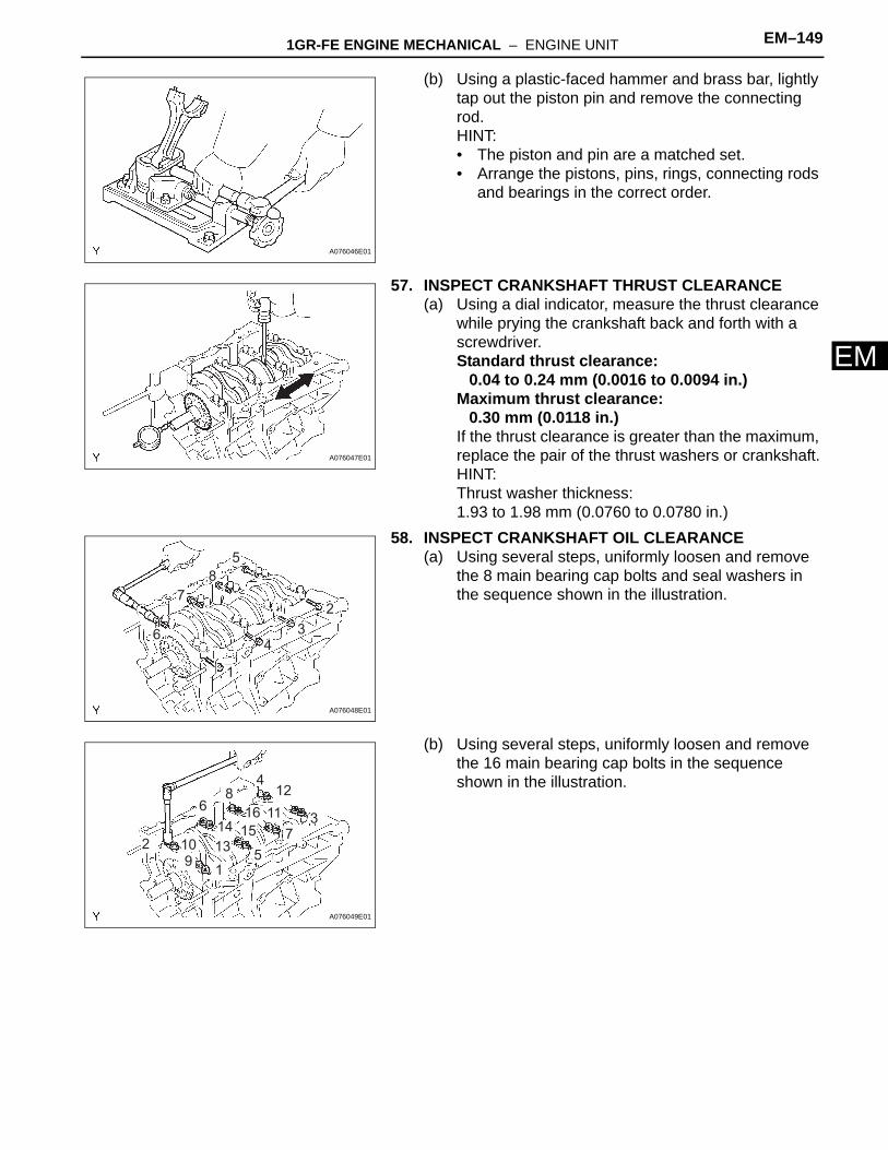
57. INSPECT CRANKSHAFT THRUST CLEARANCE(a) Using a dial indicator, measure the thrust clearance
while prying the crankshaft back and forth with a screwdriver.Standard thrust clearance:
0.04 to 0.24 mm (0.0016 to 0.0094 in.)Maximum thrust clearance:
0.30 mm (0.0118 in.)If the thrust clearance is greater than the maximum, replace the pair of the thrust washers or crankshaft.HINT:Thrust washer thickness:1.93 to 1.98 mm (0.0760 to 0.0780 in.)
58. INSPECT CRANKSHAFT OIL CLEARANCE(a) Using several steps, uniformly loosen and remove
the 8 main bearing cap bolts and seal washers in the sequence shown in the illustration.
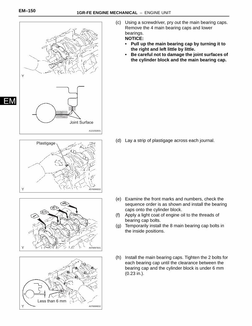
(b) Using several steps, uniformly loosen and remove the 16 main bearing cap bolts in the sequence shown in the illustration.
A076046E01
A076047E01
6
1
7
8
5
2
34
A076048E01
1
3
2 109
4
5
6
7
8
13
14
12
11
15
16
A076049E01
EM–150 1GR-FE ENGINE MECHANICAL – ENGINE UNIT
EM
(c) Using a screwdriver, pry out the main bearing caps. Remove the 4 main bearing caps and lower bearings.NOTICE:• Pull up the main bearing cap by turning it to
the right and left little by little.• Be careful not to damage the joint surfaces of
the cylinder block and the main bearing cap.
(d) Lay a strip of plastigage across each journal.
(e) Examine the front marks and numbers, check the sequence order is as shown and install the bearing caps onto the cylinder block.
(f) Apply a light coat of engine oil to the threads of bearing cap bolts.
(g) Temporarily install the 8 main bearing cap bolts in the inside positions.
(h) Install the main bearing caps. Tighten the 2 bolts for each bearing cap until the clearance between the bearing cap and the cylinder block is under 6 mm (0.23 in.).
Joint Surface
A121032E01
Plastigage
A076066E02
A076067E01
Less than 6 mmA076069E02
1GR-FE ENGINE MECHANICAL – ENGINE UNIT EM–151
M
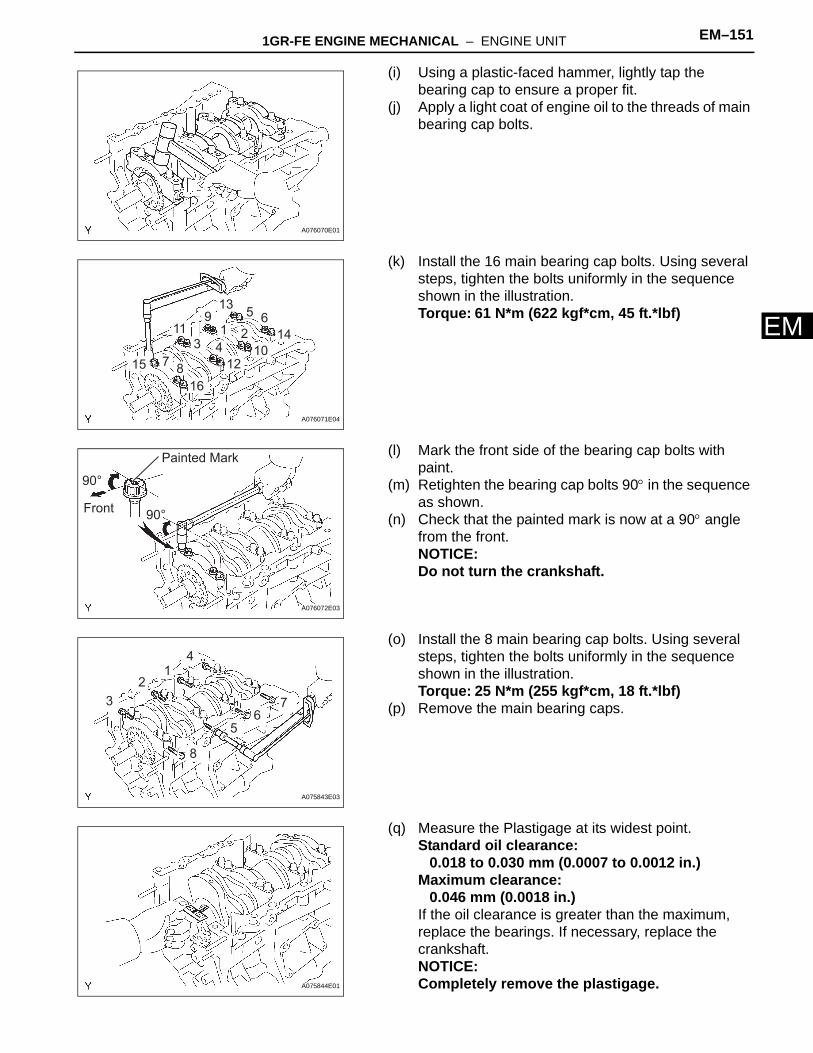
E(i) Using a plastic-faced hammer, lightly tap the bearing cap to ensure a proper fit.
(j) Apply a light coat of engine oil to the threads of main bearing cap bolts.
(k) Install the 16 main bearing cap bolts. Using several steps, tighten the bolts uniformly in the sequence shown in the illustration.Torque: 61 N*m (622 kgf*cm, 45 ft.*lbf)
(l) Mark the front side of the bearing cap bolts with paint.
(m) Retighten the bearing cap bolts 90° in the sequence as shown.
(n) Check that the painted mark is now at a 90° angle from the front.NOTICE:Do not turn the crankshaft.
(o) Install the 8 main bearing cap bolts. Using several steps, tighten the bolts uniformly in the sequence shown in the illustration.Torque: 25 N*m (255 kgf*cm, 18 ft.*lbf)
(p) Remove the main bearing caps.
(q) Measure the Plastigage at its widest point.Standard oil clearance:
0.018 to 0.030 mm (0.0007 to 0.0012 in.)Maximum clearance:
0.046 mm (0.0018 in.)If the oil clearance is greater than the maximum, replace the bearings. If necessary, replace the crankshaft.NOTICE:Completely remove the plastigage.
A076070E01
715
1 23 4
65
8
9
14
13
10
11
12
16
A076071E04
Painted Mark
Front
90°
90°
A076072E03
3 7
12
4
56
8
A075843E03
A075844E01
EM–152 1GR-FE ENGINE MECHANICAL – ENGINE UNIT
EM
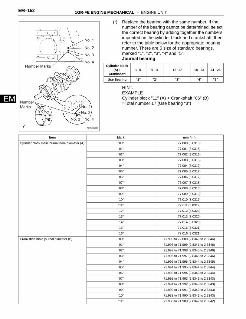
(r) Replace the bearing with the same number. If the number of the bearing cannot be determined, select the correct bearing by adding together the numbers imprinted on the cylinder block and crankshaft, then refer to the table below for the appropriate bearing number. There are 5 size of standard bearings, marked "1", "2", "3", "4" and "5".Journal bearing
HINT:EXAMPLECylinder block "11" (A) + Crankshaft "06" (B)=Total number 17 (Use bearing "3")
Number Marks
Number
Marks
No. 1
No. 1
No. 2
No. 2
No. 3
No. 3
No. 4
No. 4
A075845E03
Cylinder block (A) +
Crankshaft0 -5 6 -11 12 -17 18 - 23 24 - 28
Use Bearing "1" "2" "3" "4" "5"
Item Mark mm (in.)
Cylinder block main journal bore diameter (A) "00" 77.000 (3.0315)
"01" 77.001 (3.0315)
"02" 77.002 (3.0316)
"03" 77.003 (3.0316)
"04" 77.004 (3.0317)
"05" 77.005 (3.0317)
"06" 77.006 (3.0317)
"07" 77.007 (3.0318)
"08" 77.008 (3.0318)
"09" 77.009 (3.0319)
"10" 77.010 (3.0319)
"11" 77.011 (3.0319)
"12" 77.012 (3.0320)
"13" 77.013 (3.0320)
"14" 77.014 (3.0320)
"15" 77.015 (3.0321)
"16" 77.016 (3.0321)
Crankshaft main journal diameter (B) "00" 71.999 to 72.000 (2.8346 to 2.8346)
"01" 71.998 to 71.999 (2.8346 to 2.8346)
"02" 71.997 to 71.998 (2.8345 to 2.8346)
"03" 71.996 to 71.997 (2.8345 to 2.8346)
"04" 71.995 to 71.996 (2.8344 to 2.8345)
"05" 71.994 to 71.995 (2.8344 to 2.8344)
"06" 71.993 to 71.994 (2.8343 to 2.8344)
"07" 71.992 to 71.993 (2.8343 to 2.8343)
"08" 71.991 to 71.992 (2.8343 to 2.8343)
"09" 71.990 to 71.991 (2.8343 to 2.8343)
"10" 71.989 to 71.990 (2.8342 to 2.8343)
"11" 71.988 to 71.989 (2.8342 to 2.8342)
1GR-FE ENGINE MECHANICAL – ENGINE UNIT EM–153
M
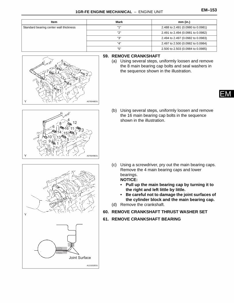
E59. REMOVE CRANKSHAFT(a) Using several steps, uniformly loosen and remove
the 8 main bearing cap bolts and seal washers in the sequence shown in the illustration.
(b) Using several steps, uniformly loosen and remove the 16 main bearing cap bolts in the sequence shown in the illustration.
(c) Using a screwdriver, pry out the main bearing caps. Remove the 4 main bearing caps and lower bearings.NOTICE:• Pull up the main bearing cap by turning it to
the right and left little by little.• Be careful not to damage the joint surfaces of
the cylinder block and the main bearing cap.(d) Remove the crankshaft.
60. REMOVE CRANKSHAFT THRUST WASHER SET61. REMOVE CRANKSHAFT BEARING
Standard bearing center wall thickness "1" 2.488 to 2.491 (0.0980 to 0.0981)
"2" 2.491 to 2.494 (0.0981 to 0.0982)
"3" 2.494 to 2.497 (0.0982 to 0.0983)
"4" 2.497 to 2.500 (0.0982 to 0.0984)
"5" 2.500 to 2.503 (0.0984 to 0.0985)
Item Mark mm (in.)
6
1
7
8
5
2
34
A076048E01
1
3
2 109
4
5
6
7
8
13
14
12
11
15
16
A076049E01
Joint Surface
A121032E01
EM–154 1GR-FE ENGINE MECHANICAL – ENGINE UNIT
EM
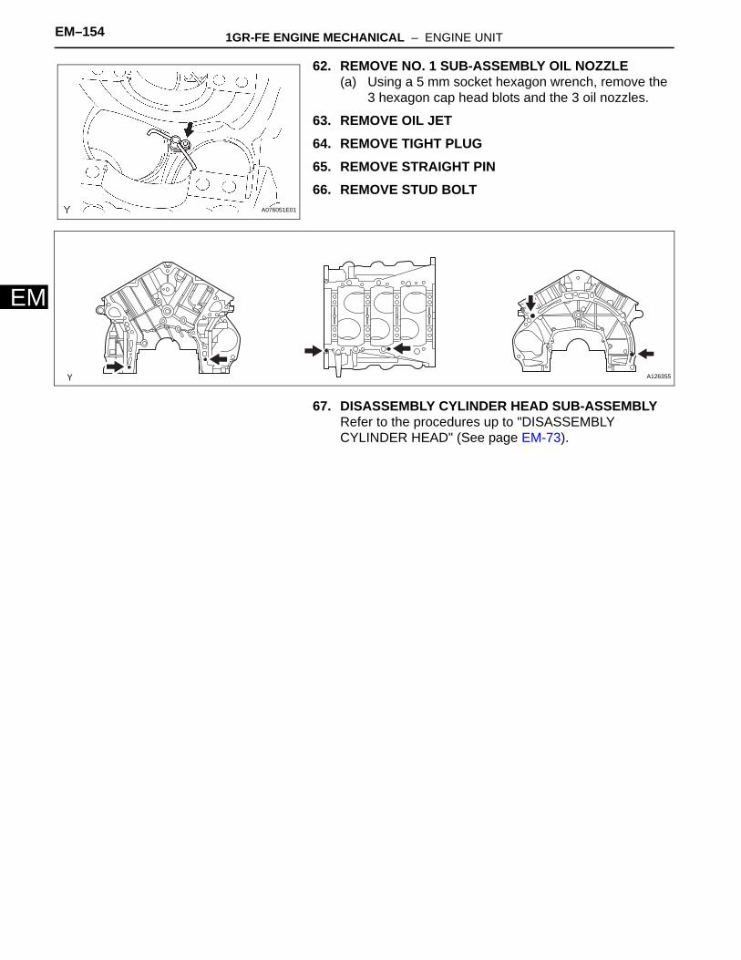
62. REMOVE NO. 1 SUB-ASSEMBLY OIL NOZZLE(a) Using a 5 mm socket hexagon wrench, remove the
3 hexagon cap head blots and the 3 oil nozzles.
63. REMOVE OIL JET64. REMOVE TIGHT PLUG65. REMOVE STRAIGHT PIN66. REMOVE STUD BOLT
67. DISASSEMBLY CYLINDER HEAD SUB-ASSEMBLYRefer to the procedures up to "DISASSEMBLY CYLINDER HEAD" (See page EM-73).
A076051E01
Y A126355
1GR-FE ENGINE MECHANICAL – ENGINE UNIT EM–155
M
EINSPECTION1. INSPECT CAMSHAFTS (See page EM-47)2. INSPECT CAMSHAFT TIMING GEAR ASSEMBLY
(See page EM-47)3. INSPECT CYLINDER HEAD SET BOLT (See page EM-
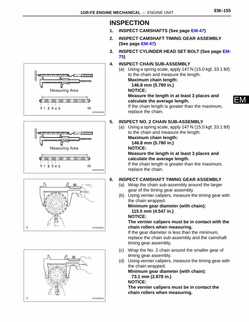
75)4. INSPECT CHAIN SUB-ASSEMBLY
(a) Using a spring scale, apply 147 N (15.0 kgf, 33.1 lbf) to the chain and measure the length.Maximum chain length:
146.8 mm (5.780 in.)NOTICE:Measure the length in at least 3 places and calculate the average length.If the chain length is greater than the maximum, replace the chain.
5. INSPECT NO. 2 CHAIN SUB-ASSEMBLY(a) Using a spring scale, apply 147 N (15.0 kgf, 33.1 lbf)
to the chain and measure the length.Maximum chain length:
146.8 mm (5.780 in.)NOTICE:Measure the length in at least 3 places and calculate the average length.If the chain length is greater than the maximum, replace the chain.
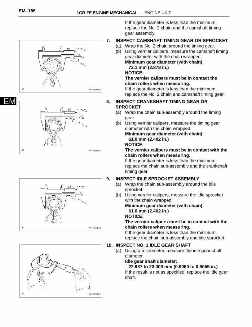
6. INSPECT CAMSHAFT TIMING GEAR ASSEMBLY(a) Wrap the chain sub-assembly around the larger
gear of the timing gear assembly.(b) Using vernier calipers, measure the timing gear with
the chain wrapped.Minimum gear diameter (with chain):
115.5 mm (4.547 in.)NOTICE:The vernier calipers must be in contact with the chain rollers when measuring.If the gear diameter is less than the minimum, replace the chain sub-assembly and the camshaft timing gear assembly.
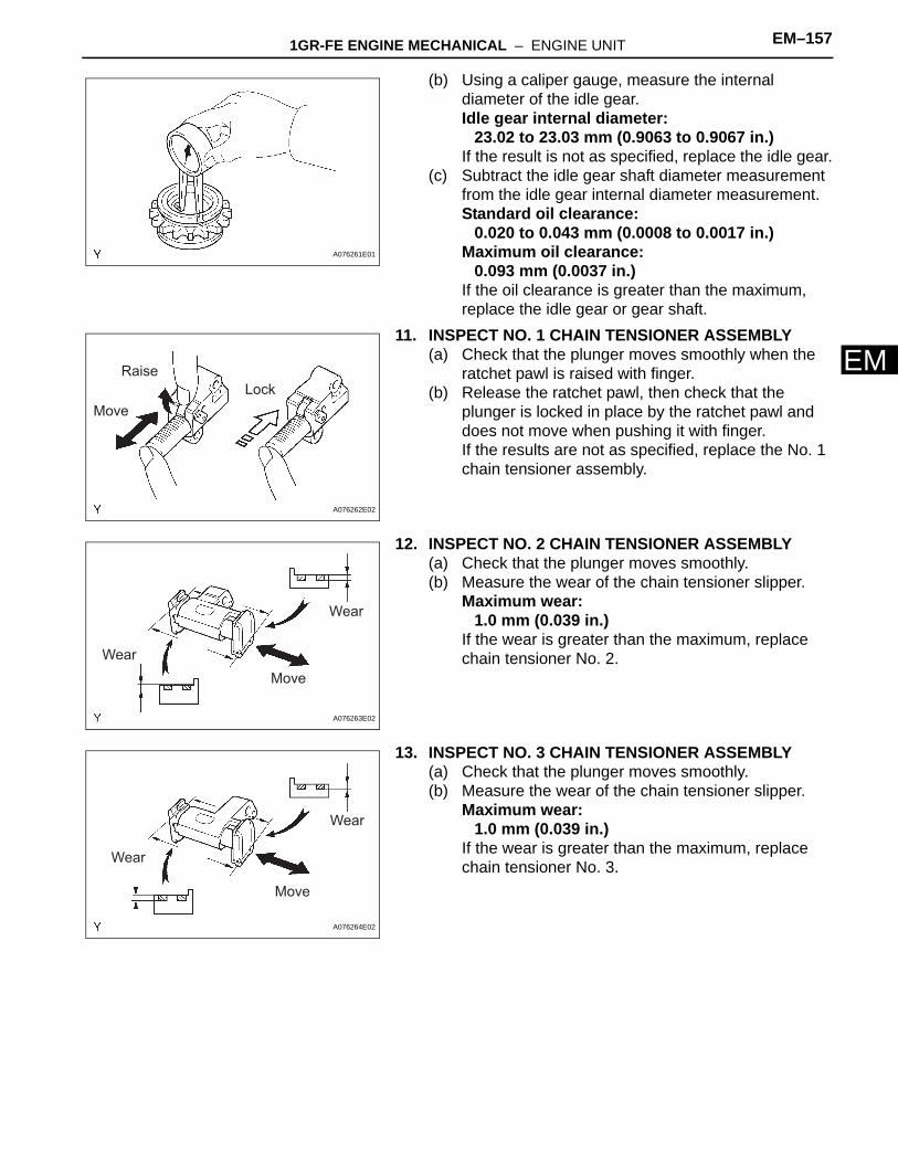
(c) Wrap the No. 2 chain around the smaller gear of timing gear assembly.
(d) Using vernier calipers, measure the timing gear with the chain wrapped.Minimum gear diameter (with chain):
73.1 mm (2.878 in.)NOTICE:The vernier calipers must be in contact the chain rollers when measuring.
Measuring Area
A053044E02
Measuring Area
A053044E02
A076255E01
A076256E01
EM–156 1GR-FE ENGINE MECHANICAL – ENGINE UNIT
EM
If the gear diameter is less than the minimum, replace the No. 2 chain and the camshaft timing gear assembly.
7. INSPECT CAMSHAFT TIMING GEAR OR SPROCKET(a) Wrap the No. 2 chain around the timing gear.(b) Using vernier calipers, measure the camshaft timing
gear diameter with the chain wrapped.Minimum gear diameter (with chain):
73.1 mm (2.878 in.)NOTICE:The vernier calipers must be in contact the chain rollers when measuring.If the gear diameter is less than the minimum, replace the No. 2 chain and camshaft timing gear.
8. INSPECT CRANKSHAFT TIMING GEAR OR SPROCKET(a) Wrap the chain sub-assembly around the timing
gear.(b) Using vernier calipers, measure the timing gear
diameter with the chain wrapped.Minimum gear diameter (with chain):
61.0 mm (2.402 in.)NOTICE:The vernier calipers must be in contact with the chain rollers when measuring.If the gear diameter is less than the minimum, replace the chain sub-assembly and the crankshaft timing gear.
9. INSPECT IDLE SPROCKET ASSEMBLY(a) Wrap the chain sub-assembly around the idle
sprocket.(b) Using vernier calipers, measure the idle sprocket
with the chain wrapped.Minimum gear diameter (with chain):
61.0 mm (2.402 in.)NOTICE:The vernier calipers must be in contact with the chain rollers when measuring.If the gear diameter is less than the minimum, replace the chain sub-assembly and idle sprocket.
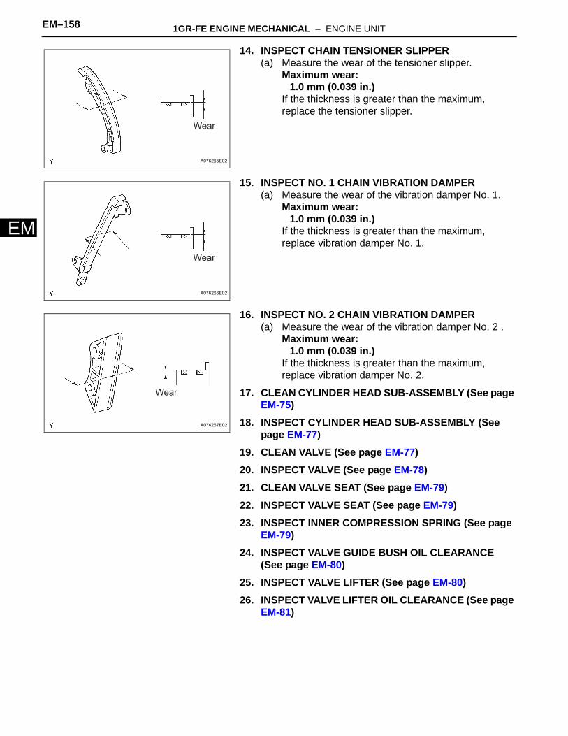
10. INSPECT NO. 1 IDLE GEAR SHAFT(a) Using a micrometer, measure the idle gear shaft
diameter.Idle gear shaft diameter:
22.987 to 23.000 mm (0.9050 to 0.9055 in.)If the result is not as specified, replace the idle gear shaft.
A076257E01
A076258E01
A076259E01
A076260E01
1GR-FE ENGINE MECHANICAL – ENGINE UNIT EM–157
M
E(b) Using a caliper gauge, measure the internal diameter of the idle gear.Idle gear internal diameter:
23.02 to 23.03 mm (0.9063 to 0.9067 in.)If the result is not as specified, replace the idle gear.
(c) Subtract the idle gear shaft diameter measurement from the idle gear internal diameter measurement.Standard oil clearance:
0.020 to 0.043 mm (0.0008 to 0.0017 in.)Maximum oil clearance:
0.093 mm (0.0037 in.)If the oil clearance is greater than the maximum, replace the idle gear or gear shaft.
11. INSPECT NO. 1 CHAIN TENSIONER ASSEMBLY(a) Check that the plunger moves smoothly when the
ratchet pawl is raised with finger.(b) Release the ratchet pawl, then check that the
plunger is locked in place by the ratchet pawl and does not move when pushing it with finger.If the results are not as specified, replace the No. 1 chain tensioner assembly.
12. INSPECT NO. 2 CHAIN TENSIONER ASSEMBLY(a) Check that the plunger moves smoothly.(b) Measure the wear of the chain tensioner slipper.
Maximum wear:1.0 mm (0.039 in.)
If the wear is greater than the maximum, replace chain tensioner No. 2.
13. INSPECT NO. 3 CHAIN TENSIONER ASSEMBLY(a) Check that the plunger moves smoothly.(b) Measure the wear of the chain tensioner slipper.
Maximum wear:1.0 mm (0.039 in.)
If the wear is greater than the maximum, replace chain tensioner No. 3.
A076261E01
Raise
Move
Lock
A076262E02
Move
Wear
Wear
A076263E02
Move
Wear
Wear
A076264E02
EM–158 1GR-FE ENGINE MECHANICAL – ENGINE UNIT
EM
14. INSPECT CHAIN TENSIONER SLIPPER(a) Measure the wear of the tensioner slipper.
Maximum wear:1.0 mm (0.039 in.)
If the thickness is greater than the maximum, replace the tensioner slipper.
15. INSPECT NO. 1 CHAIN VIBRATION DAMPER(a) Measure the wear of the vibration damper No. 1.
Maximum wear:1.0 mm (0.039 in.)
If the thickness is greater than the maximum, replace vibration damper No. 1.
16. INSPECT NO. 2 CHAIN VIBRATION DAMPER(a) Measure the wear of the vibration damper No. 2 .
Maximum wear:1.0 mm (0.039 in.)
If the thickness is greater than the maximum, replace vibration damper No. 2.
17. CLEAN CYLINDER HEAD SUB-ASSEMBLY (See page EM-75)
18. INSPECT CYLINDER HEAD SUB-ASSEMBLY (See page EM-77)
19. CLEAN VALVE (See page EM-77)20. INSPECT VALVE (See page EM-78)21. CLEAN VALVE SEAT (See page EM-79)22. INSPECT VALVE SEAT (See page EM-79)23. INSPECT INNER COMPRESSION SPRING (See page
EM-79)24. INSPECT VALVE GUIDE BUSH OIL CLEARANCE
(See page EM-80)25. INSPECT VALVE LIFTER (See page EM-80)26. INSPECT VALVE LIFTER OIL CLEARANCE (See page
EM-81)
Wear
A076265E02
Wear
A076266E02
Wear
A076267E02
1GR-FE ENGINE MECHANICAL – ENGINE UNIT EM–159
M
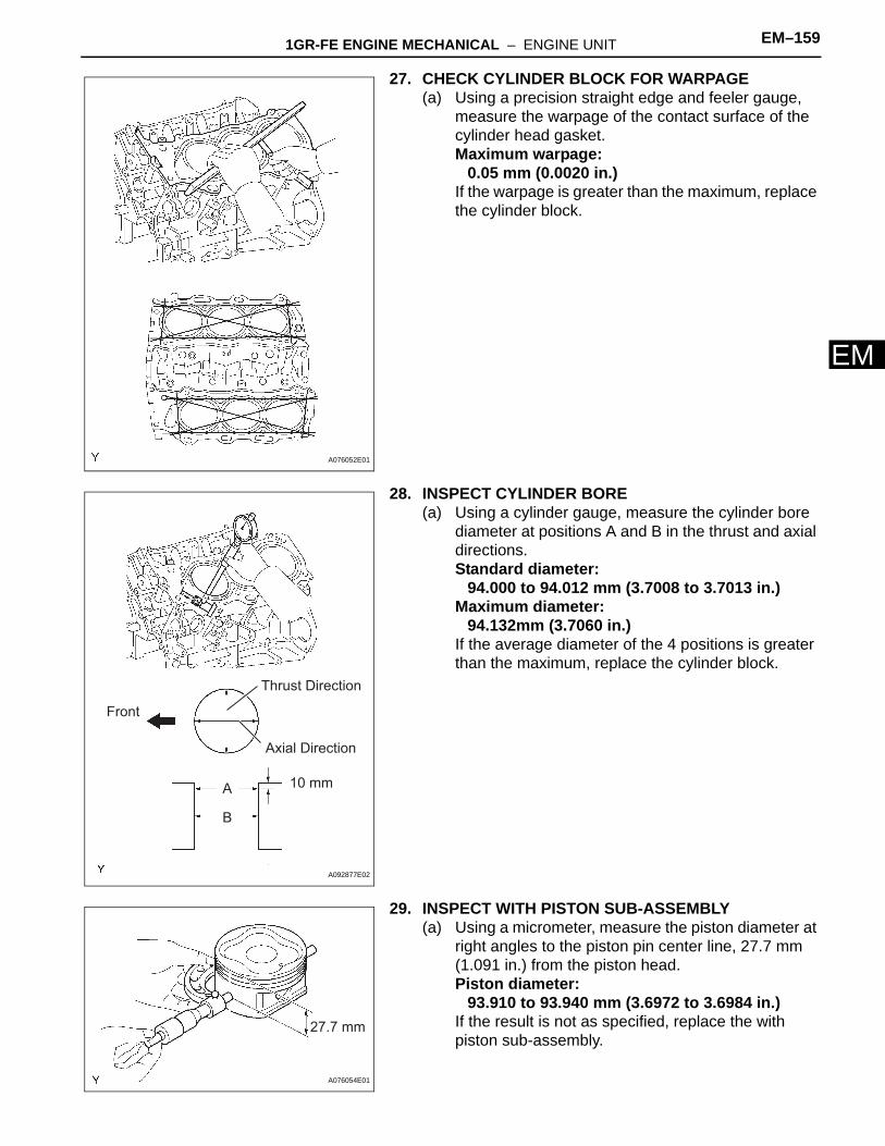
E27. CHECK CYLINDER BLOCK FOR WARPAGE(a) Using a precision straight edge and feeler gauge,
measure the warpage of the contact surface of the cylinder head gasket.Maximum warpage:
0.05 mm (0.0020 in.)If the warpage is greater than the maximum, replace the cylinder block.
28. INSPECT CYLINDER BORE(a) Using a cylinder gauge, measure the cylinder bore
diameter at positions A and B in the thrust and axial directions.Standard diameter:
94.000 to 94.012 mm (3.7008 to 3.7013 in.)Maximum diameter:
94.132mm (3.7060 in.)If the average diameter of the 4 positions is greater than the maximum, replace the cylinder block.
29. INSPECT WITH PISTON SUB-ASSEMBLY(a) Using a micrometer, measure the piston diameter at
right angles to the piston pin center line, 27.7 mm (1.091 in.) from the piston head.Piston diameter:
93.910 to 93.940 mm (3.6972 to 3.6984 in.)If the result is not as specified, replace the with piston sub-assembly.
A076052E01
Thrust Direction
Axial Direction
10 mmA
B
Front
A092877E02
27.7 mm
A076054E01
EM–160 1GR-FE ENGINE MECHANICAL – ENGINE UNIT
EM
30. INSPECT PISTON OIL CLEARANCE(a) Subtract the piston diameter measurement from the
cylinder bore diameter measurement.Standard oil clearance:
0.060 to 0.102 mm (0.0031 to 0.0040 in.)Maximum oil clearance:
0.13 mm (0.0051 in.)If the oil clearance is greater than the maximum, replace all the 6 pistons. If necessary, replace the cylinder block.
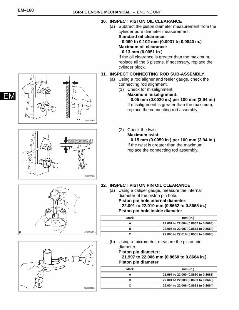
31. INSPECT CONNECTING ROD SUB-ASSEMBLY(a) Using a rod aligner and feeler gauge, check the
connecting rod alignment.(1) Check for misalignment.
Maximum misalignment:0.05 mm (0.0020 in.) per 100 mm (3.94 in.)
If misalignment is greater than the maximum, replace the connecting rod assembly.
(2) Check the twist.Maximum twist:
0.15 mm (0.0059 in.) per 100 mm (3.94 in.)If the twist is greater than the maximum, replace the connecting rod assembly.
32. INSPECT PISTON PIN OIL CLEARANCE(a) Using a caliper gauge, measure the internal
diameter of the piston pin hole.Piston pin hole internal diameter:
22.001 to 22.010 mm (0.8662 to 0.8665 in.)Piston pin hole inside diameter
(b) Using a micrometer, measure the piston pin diameter.Piston pin diameter:
21.997 to 22.006 mm (0.8660 to 0.8664 in.)Piston pin diameter
Z000064E01
Z000065E01
A013490E01
Mark mm (in.)
A 22.001 to 22.004 (0.8662 to 0.8663)
B 22.005 to 22.007 (0.8663 to 0.8664)
C 22.008 to 22.010 (0.8665 to 0.8665)
EM00227E01
Mark mm (in.)
A 21.997 to 22.000 (0.8660 to 0.8661)
B 22.001 to 22.003 (0.8661 to 0.8663)
C 22.004 to 22.006 (0.8663 to 0.8664)

1GR-FE ENGINE MECHANICAL – ENGINE UNIT EM–161
M
E(c) Using a caliper gauge, measure the internal diameter of the connecting rod bushing.Bushing internal diameter:
22.005 to 22.014 mm (0.8663 to 0.8667 in.)Bushing internal diameter
(d) Subtract the piston pin diameter measurement from the piton pin hole diameter measurement.Standard oil clearance:
0.001 to 0.007 mm (0.00004 to 0.00028 in.)Maximum oil clearance:
0.040 mm (0.0016 in.)(e) If the oil clearance is greater than the maximum,
replace the bushing. If necessary, replace the piston and piston pin together.
(f) Subtract the piston pin diameter measurement from the bushing inside diameter measurement.Standard oil clearance:
0.005 to 0.011 mm (0.0002 to 0.0004 in.)Maximum oil clearance:
0.050 mm (0.0020 in.)(g) If the oil clearance is greater than the maximum,
replace the bushing. If necessary, replace the connecting rod and piston pin together.
33. INSPECT RING GROOVE CLEARANCE(a) Using a feeler gauge, measure the clearance
between a new piston ring and the wall of the ring groove.Ring groove clearance
A076055E01
Mark mm (in.)
A 22.005 to 22.008 (0.8663 to 0.8665)
B 22.009 to 22.011 (0.8665 to 0.8666)
C 22.012 to 22.014 (0.8666 to 0.8667)
Front Mark
Piston Pin
Hole Inside
Diameter
Mark
Front Mark
Connecting Rod
Bushing Inside
Diameter Mark
A076391E02
A076056E01
Piston ring Specification
No. 1 0.02 to 0.07 mm (0.0008 to 0.0028 in.)
No. 2 0.02 to 0.06 mm (0.0008 to 0.0024 in.)
Oil 0.07 to 0.15 mm (0.0028 to 0.0060 in.)
EM–162 1GR-FE ENGINE MECHANICAL – ENGINE UNIT
EM
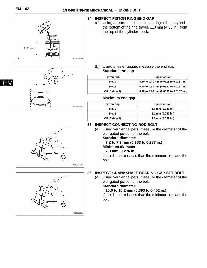
34. INSPECT PISTON RING END GAP(a) Using a piston, push the piston ring a little beyond
the bottom of the ring travel, 110 mm (4.33 in.) from the top of the cylinder block.
(b) Using a feeler gauge, measure the end gap.Standard end gap
Maximum end gap
35. INSPECT CONNECTING ROD BOLT(a) Using vernier calipers, measure the diameter of the
elongated portion of the bolt.Standard diameter:
7.2 to 7.3 mm (0.283 to 0.287 in.)Minimum diameter:
7.0 mm (0.276 in.)If the diameter is less than the minimum, replace the bolt.
36. INSPECT CRANKSHAFT BEARING CAP SET BOLT(a) Using vernier calipers, measure the diameter of the
elongated portion of the bolt.Standard diameter:
10.0 to 10.2 mm (0.393 to 0.402 in.)If the diameter is less than the minimum, replace the bolt.
110 mm
A076057E02
A037355E01
Piston ring Specification
No. 1 0.30 to 0.40 mm (0.0118 to 0.0157 in.)
No. 2 0.40 to 0.50 mm (0.0157 to 0.0197 in.)
Oil (Side rail) 0.10 to 0.40 mm (0.0039 to 0.0157 in.)
Piston ring Specification
No. 1 1.0 mm (0.039 in.)
No. 2 1.1 mm (0.043 in.)
Oil (Side rail) 1.0 mm (0.039 in.)
A015065E01
A015065E01
1GR-FE ENGINE MECHANICAL – ENGINE UNIT EM–163
M
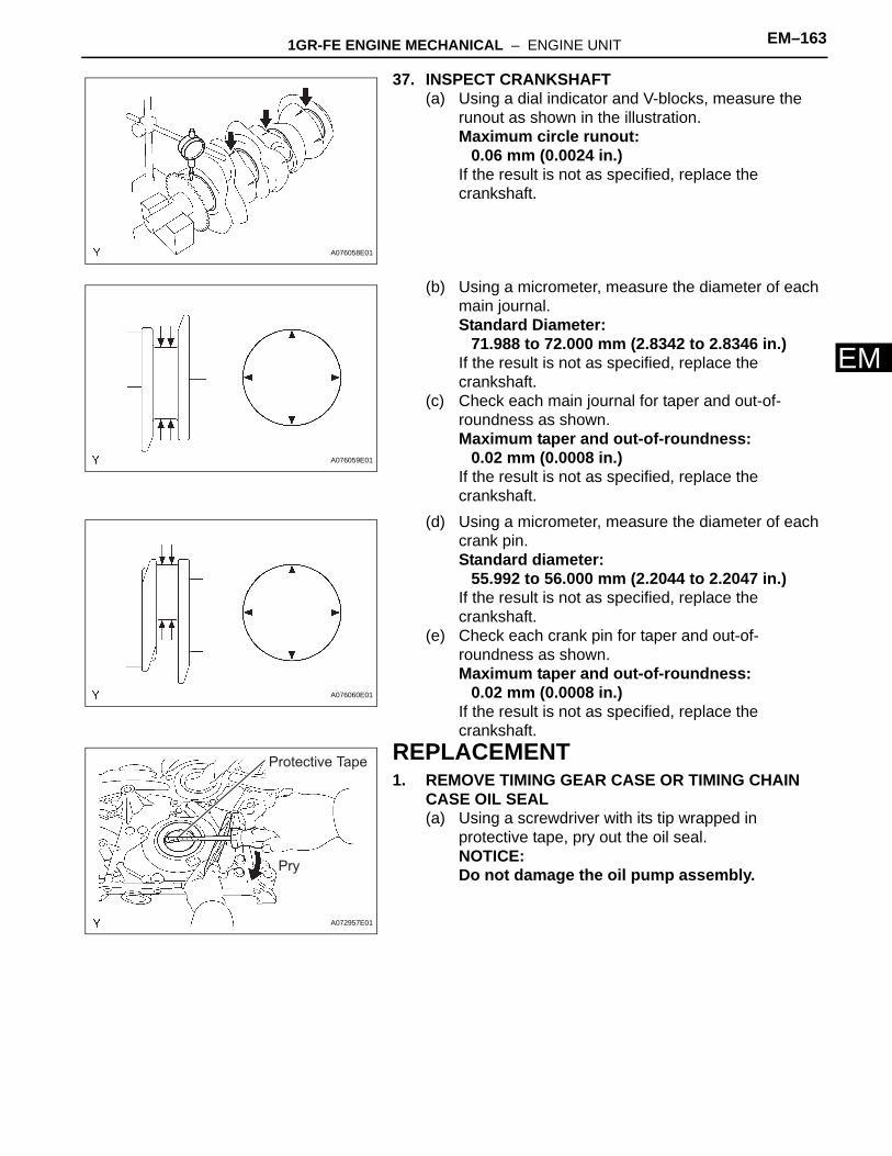
E37. INSPECT CRANKSHAFT(a) Using a dial indicator and V-blocks, measure the
runout as shown in the illustration.Maximum circle runout:
0.06 mm (0.0024 in.)If the result is not as specified, replace the crankshaft.
(b) Using a micrometer, measure the diameter of each main journal.Standard Diameter:
71.988 to 72.000 mm (2.8342 to 2.8346 in.)If the result is not as specified, replace the crankshaft.
(c) Check each main journal for taper and out-of-roundness as shown.Maximum taper and out-of-roundness:
0.02 mm (0.0008 in.)If the result is not as specified, replace the crankshaft.
(d) Using a micrometer, measure the diameter of each crank pin.Standard diameter:
55.992 to 56.000 mm (2.2044 to 2.2047 in.)If the result is not as specified, replace the crankshaft.
(e) Check each crank pin for taper and out-of-roundness as shown.Maximum taper and out-of-roundness:
0.02 mm (0.0008 in.)If the result is not as specified, replace the crankshaft.
REPLACEMENT1. REMOVE TIMING GEAR CASE OR TIMING CHAIN
CASE OIL SEAL(a) Using a screwdriver with its tip wrapped in
protective tape, pry out the oil seal.NOTICE:Do not damage the oil pump assembly.
A076058E01
A076059E01
A076060E01
Protective Tape
Pry
A072957E01
EM–164 1GR-FE ENGINE MECHANICAL – ENGINE UNIT
EM
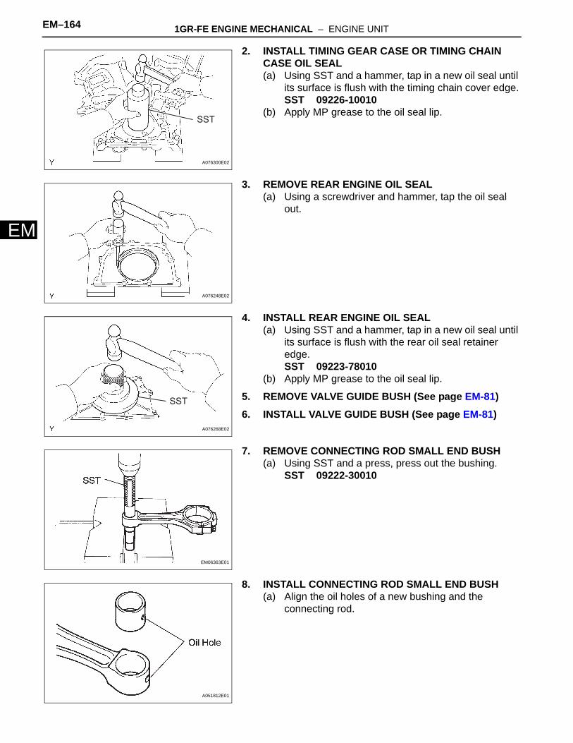
2. INSTALL TIMING GEAR CASE OR TIMING CHAIN CASE OIL SEAL(a) Using SST and a hammer, tap in a new oil seal until
its surface is flush with the timing chain cover edge.SST 09226-10010
(b) Apply MP grease to the oil seal lip.
3. REMOVE REAR ENGINE OIL SEAL(a) Using a screwdriver and hammer, tap the oil seal
out.
4. INSTALL REAR ENGINE OIL SEAL(a) Using SST and a hammer, tap in a new oil seal until
its surface is flush with the rear oil seal retainer edge.SST 09223-78010
(b) Apply MP grease to the oil seal lip.
5. REMOVE VALVE GUIDE BUSH (See page EM-81)6. INSTALL VALVE GUIDE BUSH (See page EM-81)
7. REMOVE CONNECTING ROD SMALL END BUSH(a) Using SST and a press, press out the bushing.
SST 09222-30010
8. INSTALL CONNECTING ROD SMALL END BUSH(a) Align the oil holes of a new bushing and the
connecting rod.
SST
A076300E02
A076248E02
SST
A076268E02
EM06363E01
A051812E01
1GR-FE ENGINE MECHANICAL – ENGINE UNIT EM–165
M
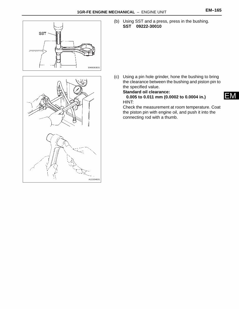
E(b) Using SST and a press, press in the bushing.SST 09222-30010
(c) Using a pin hole grinder, hone the bushing to bring the clearance between the bushing and piston pin to the specified value.Standard oil clearance:
0.005 to 0.011 mm (0.0002 to 0.0004 in.)HINT:Check the measurement at room temperature. Coat the piston pin with engine oil, and push it into the connecting rod with a thumb.
EM06363E01
A121034E01