EM31-MK2 Quick Setup Summary
16
EM31-MK2 Uses electromagnetic inductive technique that facilitates conductivity measurements without needing to be in contact with the ground. Real time readout through RS232 output port. Maps any subsurface anomaly that causes a change in the conductivity of the ground. Effective in areas of high surface resistivity [ex. gravel or sand]
Transcript of EM31-MK2 Quick Setup Summary
EM31-MK2
Uses electromagnetic inductive technique that facilitates conductivity measurements without needing to be in contact with the ground.
Real time readout through RS232 output port.
Maps any subsurface anomaly that causes a change in the conductivity of the ground.
Effective in areas of high surface resistivity [ex. gravel or sand]
EM31-MK2 STATS

Coil Spacing:
3.66 meters
Frequency:
9.8 kHz
Range:
Conductivity = 10, 100, 1K mS/m
In-Phase = ± 20 ppt
Resolution:
± 0.1% of Full Scale
Accuracy:
± 5% at 20 mS/m
Noise:
Conductivity = 0.1 mS/m
In-Phase = 0.03 ppt
Storage:
Two Component = 10,000 records
One Component = 16,500 records
Depth of exploration:
~6 meters
Apparent Conductivity:
millisiemens per metre (mS/m)
In-Phase Ratio:
Parts per thousand (ppt.)
Ratio of secondary magnetic field to the primary magnetic field.

1) CHECK THE BATTERIES a. SET MODE SWITCH→ OPERb. SET RANGE SWITCH→ BATT
c. ABSOLUTE VALUES = >4.4 (then the batteries are good) If absolute values are less than < 4.4 then the batteries must be
changed. [8 C Cell Disposables]

PROBLEM
Field PC (polycorder) doesn’t recognize its connection to the EM31-MK2 when they are connected.
THE BATTERIES ARE COMPLETELY DEAD
This is the result of the EM31-MK2 being left on for an extended period of time.
This senario can be confusing. The EM31-MK2 has no status indicators and therefore the only
method of checking the batteries is connecting the Field PC/Polycorder and reading the battery values through the DAT31W program.
If the batteries in the EM31-MK2 have been completely drained the Field PC (polycorder) will not recognize the connection of the EM-31.
If this condition is not recognized the user will embark on a long troublshooting process that will fail to fix the issue.
For this reason →The first troubleshooting step for any connection problem between the Field PC (polycorder) and the EM31-MK2 should be to replace the batteries in the EM31-MK2 (8 Disposable C Cells) and try the connection process and battery check again.

2. CHECK THE ZERO READING
Insert The Transmitter Tube.
Align red dots + guide pin and engage the clamps. BE VERY CAREFUL not to bend the pins and DO NOT drop the
tube. Hold instrument ~1 meter off of the ground
b. SET MODE SWITCH→ OPERc. SET RANGE SWITCH→ 1,000 mS/m
If the Conductivity Reading is Outside Of ± 1.0
REFER TO EM-31 Manual for DC Zero Control. DC Control is inside the battery compartment. This value rarely needs for adjustment.

3. CHECK THE IN-PHASE READING
Connect The Receiver Tube
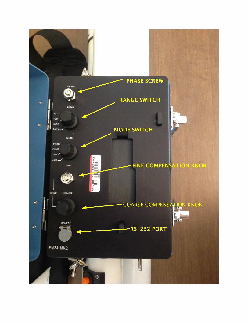
BE VERY CAREFUL DO NOT DROP TUBE OR BEND THE PINS!
a. SET MODE SWITCH→ OPERb. SET RANGE SWITCH→ 100 mS/m
Unless ground conductivity is greater than >100 mS/m If ground conductivity is greater than >100 mS/m
set the RANGE SWITCH→ 1000 mS/m. [EM-31 Manual Page 12]

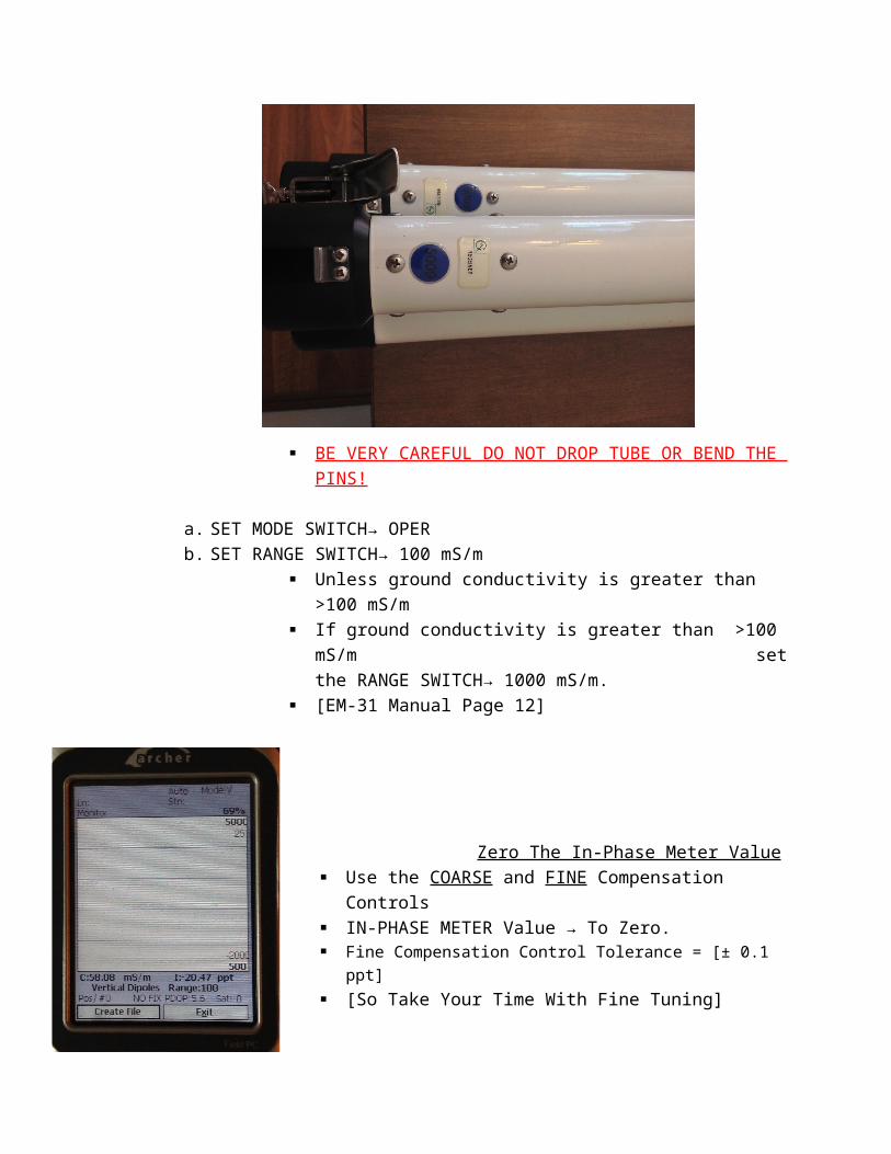
Zero The In-Phase Meter Value Use the COARSE and FINE Compensation Controls IN-PHASE METER Value → To Zero. Fine Compensation Control Tolerance = [± 0.1 ppt] [So Take Your Time With Fine Tuning]
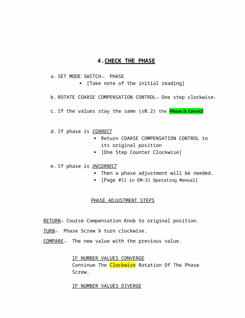
4. CHECK THE PHASE
a. SET MODE SWITCH→ PHASE [Take note of the initial reading]
b. ROTATE COARSE COMPENSATION CONTROL→ One step clockwise.
c. If the values stay the same (±0.2) the Phase Is Correct
d. If phase is CORRECT Return COARSE COMPENSATION CONTROL to its original
position [One Step Counter Clockwise]
e. If phase is INCORRECT Then a phase adjustment will be needed. [Page #11 in EM-31 Operating Manual]
PHASE ADJUSTMENT STEPS
RETURN→ Course Compensation Knob to original position.
TURN→ Phase Screw ¼ turn clockwise.
COMPARE→ The new value with the previous value.
IF NUMBER VALUES CONVERGE Continue The Clockwise Rotation Of The Phase Screw.
IF NUMBER VALUES DIVERGE Continue The Counter Clockwise Rotation Of The Phase Screw Until The Values Begin To Approach Nominal Value Of (± 0.2).
MAKE SURE THE PHASE SCREW NUT IS TIGHTENED AFTER THIS PROCESS
5. CHECK THE SENSITIVITY
a. SET MODE SWITCH→ COMP
b. ROTATE COARSE COMPENSATION CONTROL→ One Step Clockwise
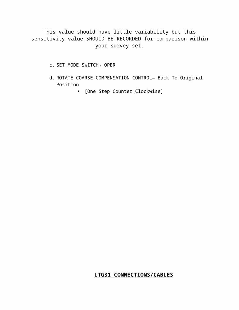
The Conductivity Value should change approximately ≈ 22-26 mS/m.
This value should have little variability but this sensitivity value SHOULD BE RECORDED for comparison within your survey set.
c. SET MODE SWITCH→ OPER
d. ROTATE COARSE COMPENSATION CONTROL→ Back To Original Position [One Step Counter Clockwise]
LTG31 CONNECTIONS/CABLES
The polycorder program GPS31 requires a cable connectiong the polycorder to the GPS Data Logger.
See [Figure 3] In LTG31 Manual

This EM31-MK2 setup is outfitted with a logger that is mounted in the instrument panel and therefore requires a two wire cable (Type 1).
INSERT PIN CONNECTOR
DIAGRAM (figure #1 & #3)
ARCHER FIELD-PC WITH GPS XF101
PROCESSOR
INTEL Xscale PXA270 520 MHz
Memory/Data
128 MB low power RAM
512 MB flash storage
OS
Microsoft Windows Mobile 6.1
PORTS
COM 1, RS-232C 9-pin D connectors
USB Host (Full A), USB Client (Mini B)
EM31 ARCHER PROGRAM