EM2510 with AMNC-F User Pre-installation Guide · EM2510 User Pre-installation Guide ©Amada...
28
EM2510 User Pre-installation Guide ©Amada America, Inc. Print Date 03/16/2004 Revision 1.0 This document available on the World Wide Web at http://www.amada.com Page 1 of 28 EM2510 with AMNC-F User Pre-installation Guide Amada America Inc. 7025 Firestone Blvd. Buena Park CA. 90621 Phone: (714) 739 2111 Fax.: (714) 739 4099 Email [email protected]
Transcript of EM2510 with AMNC-F User Pre-installation Guide · EM2510 User Pre-installation Guide ©Amada...
EM2510 User Pre-installation Guide ©Amada America, Inc.
Print Date 03/16/2004 Revision 1.0 This document available on the World Wide Web at http://www.amada.com Page 1 of 28
EM2510 with AMNC-F User Pre-installation Guide
Amada America Inc. 7025 Firestone Blvd.
Buena Park CA. 90621 Phone: (714) 739 2111
Fax.: (714) 739 4099 Email [email protected]

EM2510 User Pre-installation Guide ©Amada America, Inc.
Print Date 03/16/2004 Revision 1.0 This document available on the World Wide Web at http://www.amada.com Page 2 of 28
Warning �� Qualified personnel must complete all work. �� Do not apply power to the EM2510 until an Amada Engineer is present
and has instructed you to do so. �� Considerable effort has been made to ensure that this manual is free
of inaccuracies and omissions. However, as we are constantly improving our product, some of the data contained herein may be out of date. Please check our Internet site, http://www.amada.com, for the latest release of this document.

EM2510 User Pre-installation Guide ©Amada America, Inc.
Print Date 03/16/2004 Revision 1.0 This document available on the World Wide Web at http://www.amada.com Page 3 of 28
Contents Introduction...................................................................................................................................................................................... 4
Motion Package Specifications........................................................................................................................................................ 5
Punching System Specifications ..................................................................................................................................................... 5
AMNC-F Controller .......................................................................................................................................................................... 6
Ram Control Features: .................................................................................................................................................................... 6
Electrical Requirements................................................................................................................................................................... 7 Optional Equipment..................................................................................................................................................................... 7 Installing the Electrical Power Supply ......................................................................................................................................... 8
Pneumatic Requirements ................................................................................................................................................................ 9 Optional Equipment..................................................................................................................................................................... 9 Installing the Air Supply............................................................................................................................................................... 9
Planning the Location of the Machine ........................................................................................................................................... 10 Moving the EM2510 .................................................................................................................................................................. 10 Plan View – EM 2510 with recommended Maintenance/Safety areas. ..................................................................................... 11 Detailed Plan View - EM 2510................................................................................................................................................... 12 Elevation View – EM 2510 ........................................................................................................................................................ 13 Plan View – EM 2510................................................................................................................................................................ 14
Foundation Requirements ............................................................................................................................................................. 15
Foundation Anchoring Procedure.................................................................................................................................................. 16 Ideal Foundation Plan View ...................................................................................................................................................... 17 Ideal Foundation Elevation View............................................................................................................................................... 17 Alternative Anchoring Method (Amada Machine Mounts with Drilled Hole, Anchor Rod and Adhesive)................................... 18 Drilled Hole with Anchor Rod and Adhesive Mounting Procedure ............................................................................................ 19
Removing the Protective Coating .................................................................................................................................................. 21
Machine Leveling........................................................................................................................................................................... 22 Rocking Test ............................................................................................................................................................................. 23 Floor Condition: Crowned.......................................................................................................................................................... 24 Floor Condition: Sloped............................................................................................................................................................. 25 Leveling Procedure ................................................................................................................................................................... 26
EM2510 User Pre-installation Guide ©Amada America, Inc.
Print Date 03/16/2004 Revision 1.0 This document available on the World Wide Web at http://www.amada.com Page 4 of 28
Introduction This manual describes the tasks that the purchaser of a EM2510 must complete before calling the service organization to complete the installation and operator training. An overview of the preparations is as follows: �� Plan the location of the EM2510 in the shop, taking into account all the maintenance areas indicated on the floor plan. See
page 10, Planning the Location of the Machine, for details. �� Prepare the EM2510 floor or foundation as required. See page 15, Foundation Requirements, for details. �� Uncrate the EM2510 and place on the foundation. �� Install the electrical supply. See page 7, Electrical Requirements, for details �� Install the pneumatic supply. See page 9, Pneumatic Requirements, for details. �� Remove the protective coating from the surface of the EM2510 See page 21, Removing the Protective Coating, for details. Note: It is the purchaser’s responsibility to install any safety devices to ensure the safety area.
EM2510 User Pre-installation Guide ©Amada America, Inc.
Print Date 03/16/2004 Revision 1.0 This document available on the World Wide Web at http://www.amada.com Page 5 of 28
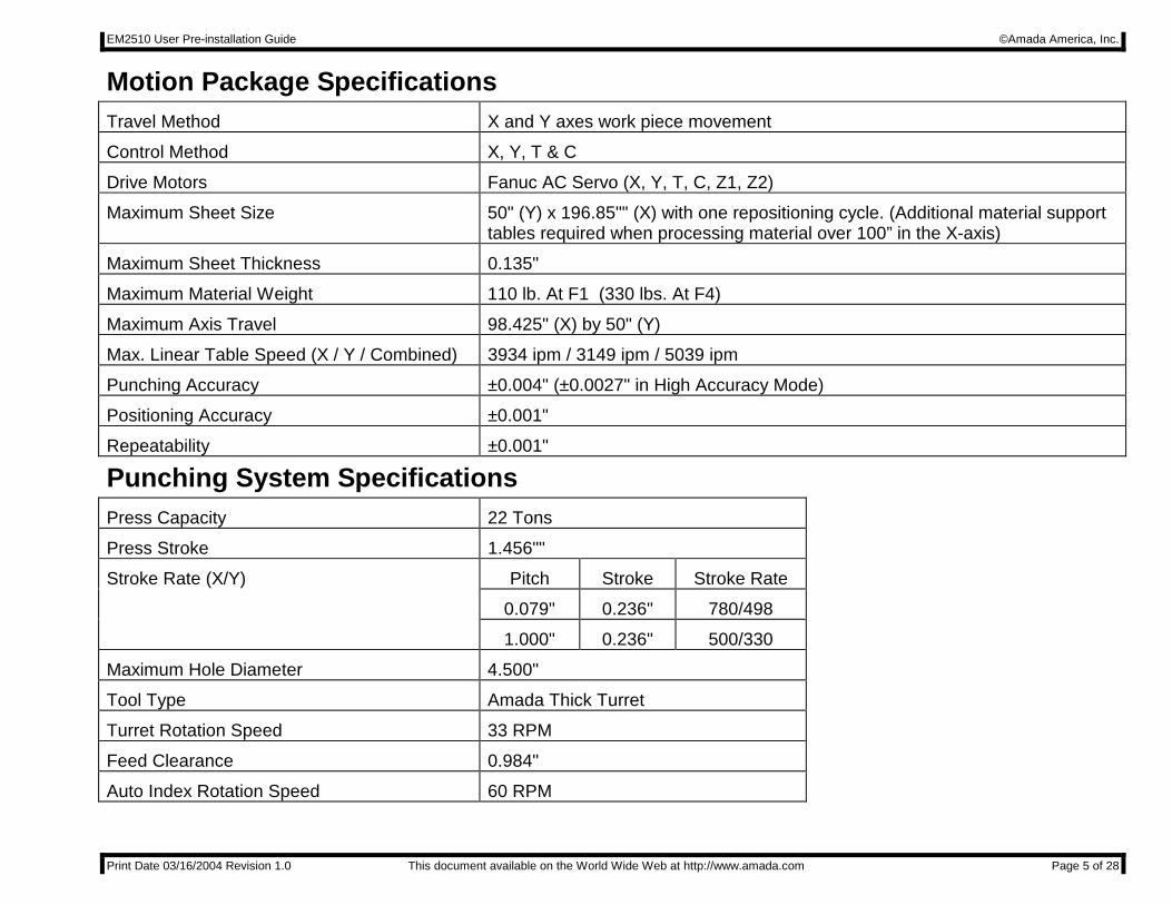
Motion Package Specifications Travel Method X and Y axes work piece movement
Control Method X, Y, T & C
Drive Motors Fanuc AC Servo (X, Y, T, C, Z1, Z2)
Maximum Sheet Size 50" (Y) x 196.85"" (X) with one repositioning cycle. (Additional material support tables required when processing material over 100” in the X-axis)
Maximum Sheet Thickness 0.135"
Maximum Material Weight 110 lb. At F1 (330 lbs. At F4)
Maximum Axis Travel 98.425" (X) by 50" (Y)
Max. Linear Table Speed (X / Y / Combined) 3934 ipm / 3149 ipm / 5039 ipm
Punching Accuracy ±0.004" (±0.0027" in High Accuracy Mode)
Positioning Accuracy ±0.001"
Repeatability ±0.001"
Punching System Specifications Press Capacity 22 Tons
Press Stroke 1.456""
Stroke Rate (X/Y) Pitch Stroke Stroke Rate
0.079" 0.236" 780/498
1.000" 0.236" 500/330
Maximum Hole Diameter 4.500"
Tool Type Amada Thick Turret
Turret Rotation Speed 33 RPM
Feed Clearance 0.984"
Auto Index Rotation Speed 60 RPM

EM2510 User Pre-installation Guide ©Amada America, Inc.
Print Date 03/16/2004 Revision 1.0 This document available on the World Wide Web at http://www.amada.com Page 6 of 28
AMNC-F Controller Model AMNC-F
Control Function X, Y, T , C, Z1, &Z2
Input Method Floppy Disk, CD ROM, USB, Ethernet, MDI, DNC
Minimum Command Unit 0.001" (X, Y) 0.010 (C)
Minimum Travel Unit 0.001" (X, Y) 0.010 (C)
Operating Modes Automatic, MDI & Manual
Display Modes Program Contents, Position Information, Program Check, Turret load, Program Set-up, Parameters, Tool Hit Counter, Self Diagnostics
Interlock Displays Door Open, Clamp Open, X-Gauge block up.
Ram Control Features:
Ram Cycle Patterns 277 Total Punching 3 Nibbling 1 Forming 250 Marking 10 Knockouts 10 Slotting 4
Minimum Programmable Increment 0.001”
EM2510 User Pre-installation Guide ©Amada America, Inc.
Print Date 03/16/2004 Revision 1.0 This document available on the World Wide Web at http://www.amada.com Page 7 of 28
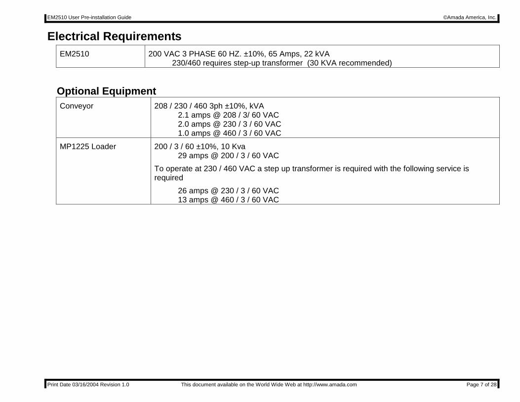
Electrical Requirements EM2510 200 VAC 3 PHASE 60 HZ. ±10%, 65 Amps, 22 kVA
230/460 requires step-up transformer (30 KVA recommended)
Optional Equipment Conveyor 208 / 230 / 460 3ph ±10%, kVA
2.1 amps @ 208 / 3/ 60 VAC 2.0 amps @ 230 / 3 / 60 VAC 1.0 amps @ 460 / 3 / 60 VAC
MP1225 Loader 200 / 3 / 60 ±10%, 10 Kva 29 amps @ 200 / 3 / 60 VAC To operate at 230 / 460 VAC a step up transformer is required with the following service is required 26 amps @ 230 / 3 / 60 VAC 13 amps @ 460 / 3 / 60 VAC

EM2510 User Pre-installation Guide ©Amada America, Inc.
Print Date 03/16/2004 Revision 1.0 This document available on the World Wide Web at http://www.amada.com Page 8 of 28
Installing the Electrical Power Supply The EM2510 should be supplied from a power line separate from those for welding machines or other machines that produce electrical noise. The EM2510 electrical inlet is 75" above floor level at the rear of the AMNC-F control.
EM2510 electrical enclosure:
POWER CABLE INLET
Main power connection

EM2510 User Pre-installation Guide ©Amada America, Inc.
Print Date 03/16/2004 Revision 1.0 This document available on the World Wide Web at http://www.amada.com Page 9 of 28
Pneumatic Requirements EM2510 80 psi @ 8.8 ft³/min.
Optional Equipment MP1225 Loader 75 psi @ 31.8 ft3/min.
Installing the Air Supply The EM2510 requires connection to a compressed air system by hose or pipe. The compressed air must be clean and dry. The minimum pipe inside diameter is ½".
The air inlet is approximately 16" above the floor level at the front-left side of the EM2510.
EM2510 User Pre-installation Guide ©Amada America, Inc.
Print Date 03/16/2004 Revision 1.0 This document available on the World Wide Web at http://www.amada.com Page 10 of 28
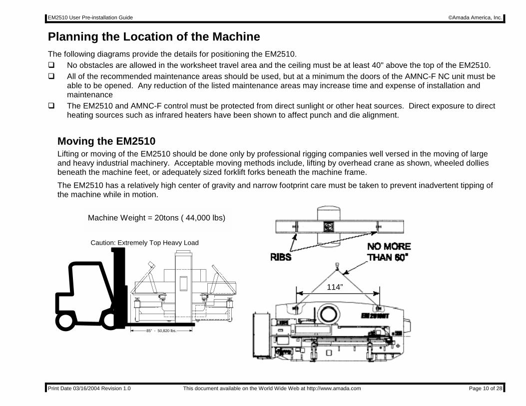
Planning the Location of the Machine The following diagrams provide the details for positioning the EM2510. �� No obstacles are allowed in the worksheet travel area and the ceiling must be at least 40" above the top of the EM2510. �� All of the recommended maintenance areas should be used, but at a minimum the doors of the AMNC-F NC unit must be
able to be opened. Any reduction of the listed maintenance areas may increase time and expense of installation and maintenance
�� The EM2510 and AMNC-F control must be protected from direct sunlight or other heat sources. Direct exposure to direct heating sources such as infrared heaters have been shown to affect punch and die alignment.
Moving the EM2510 Lifting or moving of the EM2510 should be done only by professional rigging companies well versed in the moving of large and heavy industrial machinery. Acceptable moving methods include, lifting by overhead crane as shown, wheeled dollies beneath the machine feet, or adequately sized forklift forks beneath the machine frame. The EM2510 has a relatively high center of gravity and narrow footprint care must be taken to prevent inadvertent tipping of the machine while in motion.
85" - 50,820 lbs.
Caution: Extremely Top Heavy Load
114”
Machine Weight = 20tons ( 44,000 lbs)
EM2510 User Pre-installation Guide ©Amada America, Inc.
Print Date 03/16/2004 Revision 1.0 This document available on the World Wide Web at http://www.amada.com Page 11 of 28
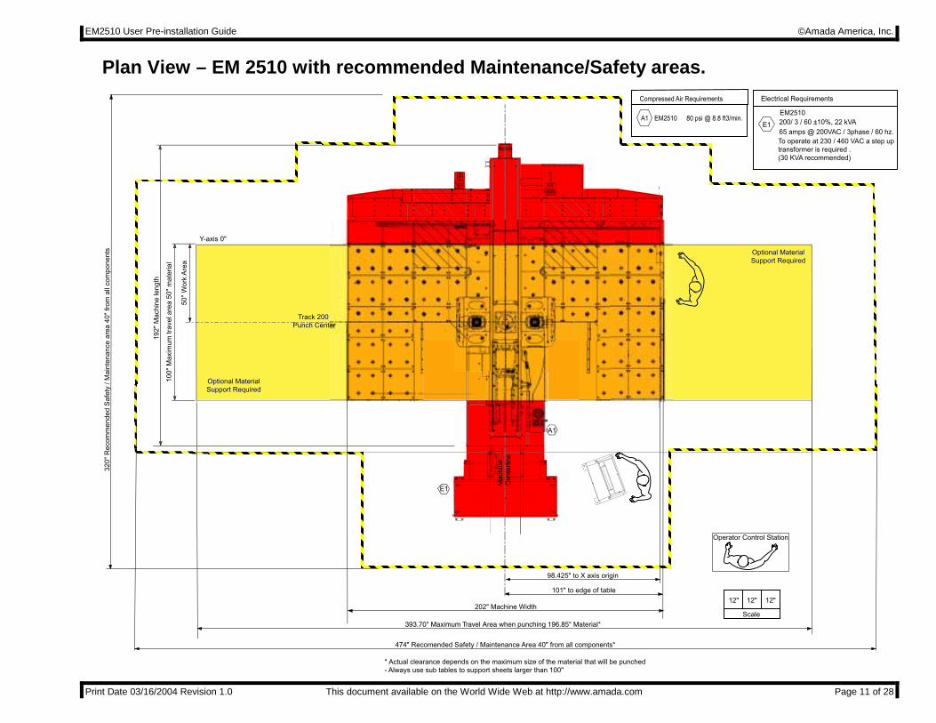
Plan View – EM 2510 with recommended Maintenance/Safety areas.
EM2510 User Pre-installation Guide ©Amada America, Inc.
Print Date 03/16/2004 Revision 1.0 This document available on the World Wide Web at http://www.amada.com Page 12 of 28
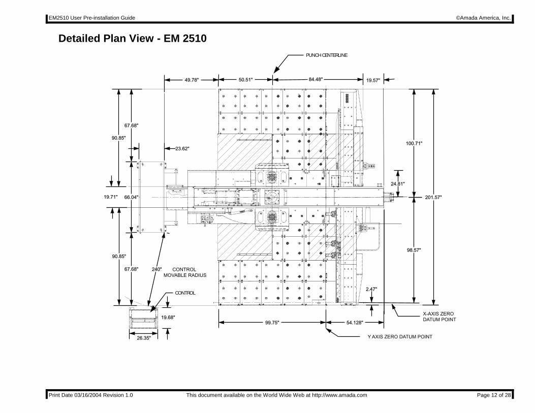
Detailed Plan View - EM 2510 PUNCH CENTERLINE
CONTROL
CONTROL MOVABLE RADIUS
54.128"99.75"
23.62"
49.78" 50.51" 84.48" 19.57"
26.35"
19.68"
90.85"
67.68"
66.04"19.71"
90.85"
67.68"
100.71"
201.57"
2.47"
98.57"
24.81"
X-AXIS ZERODATUM POINT
Y AXIS ZERO DATUM POINT
240"
EM2510 User Pre-installation Guide ©Amada America, Inc.
Print Date 03/16/2004 Revision 1.0 This document available on the World Wide Web at http://www.amada.com Page 13 of 28
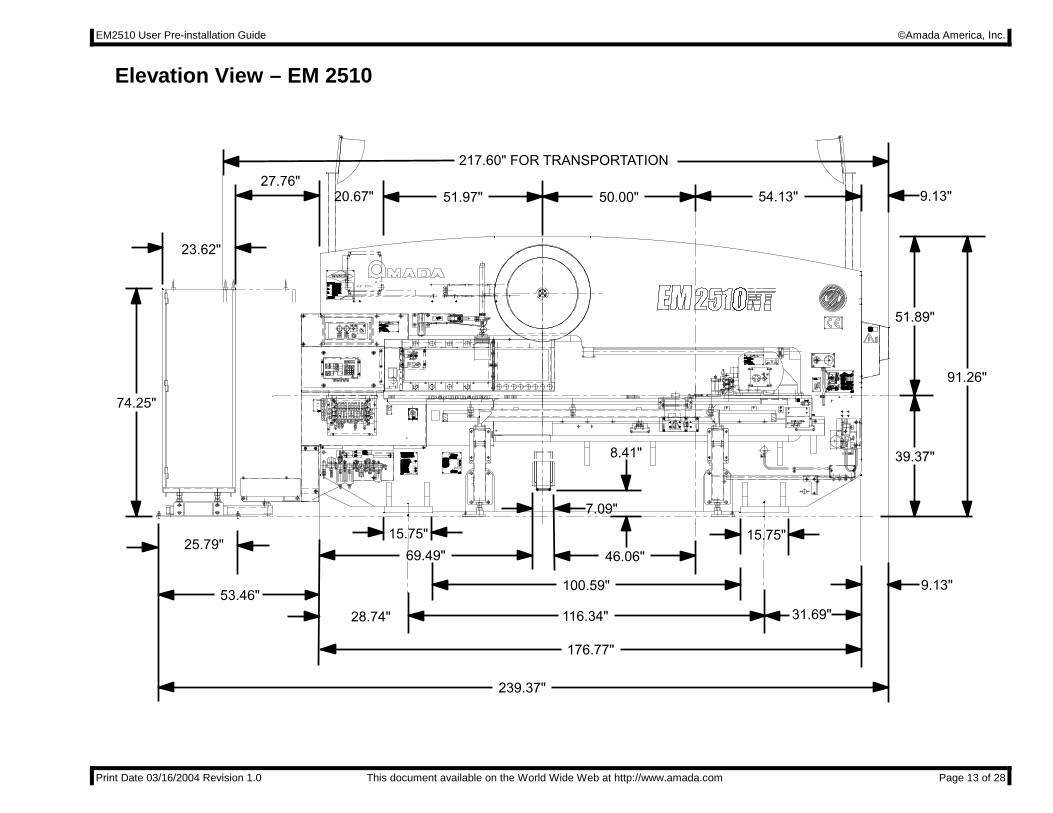
Elevation View – EM 2510
HIHILOWLOW
PR
R
RP
R
A
B
A
B
A
B
A
B
A
B
A
B
A
B
A
B
A
B
A
B
68222546822254
Y AXIS Y AXIS GUIDE NUTGUIDE NUT
68200656820065
h m c d w @ o h mi t o o d q j
x @ ‘ w h ra d ‘ q h m f
h m c d w @ o h mi k n v d q j
r s q h j d q
POUR CONSERVER UN FONCTIONNEMENT EN TOUTEPOUR CONSERVER UN FONCTIONNEMENT EN TOUTESECURITE,N’UTILISER QUE DES PIECES DE RECHANGESECURITE,N’UTILISER QUE DES PIECES DE RECHANGED’ORIGINE.D’ORIGINE.
TO ENSURE CONTINUED SAFE WORKING USE ONLYTO ENSURE CONTINUED SAFE WORKING USE ONLYAUTHORIZED REPLACEMENT PARTS.AUTHORIZED REPLACEMENT PARTS.
GUTE FUNKTION UND SICHEREIT IST NUR MIT ORIGINALGUTE FUNKTION UND SICHEREIT IST NUR MIT ORIGINALERSATZTEILEN MOGLICHERSATZTEILEN MOGLICH
OVERALL RESPONSE TIME+IMMATERIAL GUARDOVERALL RESPONSE TIME+IMMATERIAL GUARDTEMPS DE REPONSE MACHINE+BARRAGE.TEMPS DE REPONSE MACHINE+BARRAGE.
GESAMTREAKTIONSZEIT+LICHTVORHANG.GESAMTREAKTIONSZEIT+LICHTVORHANG.
DISTANCE MINI DE SECURITE.DISTANCE MINI DE SECURITE.MINIMUM SEPARATION DISTANCE.MINIMUM SEPARATION DISTANCE.KLEINSTER SICHERHEITSABSTAND.KLEINSTER SICHERHEITSABSTAND.
LONGUEUR DU CHAMP PROTEGE.LONGUEUR DU CHAMP PROTEGE.WIDTH GUARDED AREA.WIDTH GUARDED AREA.GROSSTE SCHUTZFELDBREITE.GROSSTE SCHUTZFELDBREITE.
TEMPS D’ARRET MACHINE.TEMPS D’ARRET MACHINE.STOPPING TIME.STOPPING TIME.NACHLAUFZEIT.NACHLAUFZEIT.
DISTANCE D’ARREET MACHINE.DISTANCE D’ARREET MACHINE.STOPPING DISTANCE.STOPPING DISTANCE.NACHLAUFWEG.NACHLAUFWEG.
o d q @ ‘ r r h b t q ‘ q d @ t m @ e t m y h n m ‘ l d m s nb n l o k d s ‘ l d m s d @ r h b t q n D @ t s h k h y y ‘ q dr n k n @ o ‘ q s h @ c h @ q h b ‘ l a h n @ n q h f h m ‘ k h D
TEMPO DI RISPOSTA MACCHINA+BARRIERA.TEMPO DI RISPOSTA MACCHINA+BARRIERA.
DISTANZA MINIMA DI SICUREZZA.DISTANZA MINIMA DI SICUREZZA.
LUNGHEZZA AREA PROTETTA.LUNGHEZZA AREA PROTETTA.
TEMPO DI ARRESTO MACCHINA.TEMPO DI ARRESTO MACCHINA.
DISTANZA DI ARRESTO MACCHINA.DISTANZA DI ARRESTO MACCHINA.
msms
m
i j
msms
mmmm
l ‘ c d @ h mi ‘ o ‘ m65930046593004
WEIGHT/POIDSWEIGHT/POIDSAPPROXIMATIF/APPROXIMATIF/MASCHINENGEWICHT/PESOMASCHINENGEWICHT/PESO
CNCCNCTURRETTURRETPUNCHPUNCHPRESS/POINCONNEUSEPRESS/POINCONNEUSEACNCN
CAPACITY/FORCECAPACITY/FORCEPOINCONNAGE/POINCONNAGE/MAX.STANZKRAFT/CAPACITAMAX.STANZKRAFT/CAPACITA
r d q h ‘ k @ m D ^ m D r d q h d ^ r d q h d m @ m q D ^m D r d q h d
kVAkVA
kNkN
CNCCNCREVOLVERSTANZPRESSE/PUNZONATRICEREVOLVERSTANZPRESSE/PUNZONATRICECNCCNCATORRETTATORRETTA
MODEL/MODELE/MODELL/MODELLOMODEL/MODELE/MODELL/MODELLO
m D n e@s t q q d s@r s ‘ s h n m r ^ m n l a q d@c n t s h k r ^q d u n k u d q r s ‘ s h n m d m ^ m D r s ‘ y h n m h@s n q q d s s ‘
c ‘ s d@l ‘ m t e ‘ b s t q d c ^ c ‘ s d@c d@e ‘ a q h b ‘ s h n m ^o q n c t j s h n m r c ‘ s t l ^ c ‘ s ‘@e ‘ a a q h b ‘ y h n m d
POWERPOWERREQUIRED/PUISSANCE/REQUIRED/PUISSANCE/MAX.ANSCHLUSSLEISTUNG/POTENZAMAX.ANSCHLUSSLEISTUNG/POTENZARICHIESTARICHIESTA
68264156826415l ‘ c d @ h m @ i ‘ o ‘ m
l ‘ m t e ‘ b s t q d c @ a x
‘ l ‘ c ‘ @ l ‘ b g h m h b r @ b n D C k s c
123.ISHIDA,ISEHARA-SHI,123.ISHIDA,ISEHARA-SHI,KANAGAWA PREF.,JAPANKANAGAWA PREF.,JAPAN
‘ @ b D C k
200.ISHIDA,ISEHARA-SHI,200.ISHIDA,ISEHARA-SHI,KANAGAWA PREF.,JAPANKANAGAWA PREF.,JAPAN
Y-AXIS MOTORY-AXIS MOTOR
MOTORE ASSE-YMOTORE ASSE-Y
Y-ACHSEN MOTORY-ACHSEN MOTOR
MOTEUR AXE-YMOTEUR AXE-Y
AIR PRESSUREAIR PRESSURE
PRESSION DE AIRPRESSION DE AIR
LUFTDRUCKLUFTDRUCK
PRESSIONE ARIAPRESSIONE ARIA
65930026593002
F¥R¥L 1L 1
TURRET JOG ONTURRET JOG ON
TO PREVENT SERIOUS BODY INJURYTO PREVENT SERIOUS BODY INJURY
USE THIS MACHINE WITHOUT GUARDS OR SAFETYUSE THIS MACHINE WITHOUT GUARDS OR SAFETY
DEVICES THAT ARE INTENDED TO PREVENT HANDSDEVICES THAT ARE INTENDED TO PREVENT HANDS
FROM REMAINING IN DIE SPASE.FROM REMAINING IN DIE SPASE.
OPERATE,SERVICE OR ADJUST THIS MACHINE,OROPERATE,SERVICE OR ADJUST THIS MACHINE,OR
INSTALL DIES,WITHOUT PROPER INSIRUCTIONINSTALL DIES,WITHOUT PROPER INSIRUCTION
AND WITHOUT FIRST READING AND UNDERSTAND-AND WITHOUT FIRST READING AND UNDERSTAND-
MACHINE MANUAL.MACHINE MANUAL.
ING THE INSTRUCTIONS IN THE OPERATORS ORING THE INSTRUCTIONS IN THE OPERATORS OR
INSTALL PUNCHES & DIES WITHOUT OPENINGINSTALL PUNCHES & DIES WITHOUT OPENING
TOOL CHANGE GUARD OR WHILE NOT IN PROPERTOOL CHANGE GUARD OR WHILE NOT IN PROPER
TOOL CHANGE POSITION.TOOL CHANGE POSITION.
WORK SAFETY AT ALL TIMESWORK SAFETY AT ALL TIMES
DO NOT REMOVE THIS SIGN FROM THIS MACHINEDO NOT REMOVE THIS SIGN FROM THIS MACHINE
NEVERNEVER
NEVERNEVER
NEVERNEVER
DANGERDANGER
s @
@ D
CHECK CLEAR AREACHECK CLEAR AREA
BEFORE OPERATION BEFORE OPERATION
STOP BUTTON STOP BUTTON
@ @ @ D
TOOL CHANGE SWITCH ON TOOL CHANGE SWITCH ON
TOOL CHANGE DOOR TOOL CHANGE DOOR
1.1.
2.2.
3.3.
@ @ @ @ @ @ @ @ @ @ @ @ @ @ @ @ @ D
@ @ @ @ @ @ @ @ @ @ @ @ @ @ @ @ @ @ D
o @ @ @ @ @ @ @ @ @ @ @ @ @ @
s @ @ @ @ @ @ @ @ @ @ @ @ @ @ @ @ @ @ @ @
@ @ @ @ @ @ @ @ @ @ @ @ @ @ @ @ @ @ D
Beware ofBeware of
pinchingpinching
MAXIMUM LOADMAXIMUM LOAD30 Kg30 Kg
SHELLSHELL TELLUS OIL 32TELLUS OIL 32
MOBILUX EP 0MOBILUX EP 0
TERESSTIC 33TERESSTIC 33
ALVANIA GREASE 2ALVANIA GREASE 2
B
FREQUENCYFREQUENCYr n t q b dLUBRICATION POINTLUBRICATION POINT
GREASE NIPPLEGREASE NIPPLEa
s ‘ a k d @ f t h c d @ m t s
1 1
@ R STRIKERSTRIKER
b@ S
@ X
P O
CLAMPCLAMP
A
P P
Y AXIS BEARINGY AXIS BEARING
C
P Q
Y AXIS GUIDE NUTY AXIS GUIDE NUT
‘
P R TOOLS & LIFTER COLLARTOOLS & LIFTER COLLAR
A
OIL BATHOIL BATH
P S LUBRICATORLUBRICATOR
GREASE NIPPLEGREASE NIPPLE
P T
Y AXIS GEAR BOXY AXIS GEAR BOX A
QUARTERLYQUARTERLY
=
q d o k d m h r g
==
X AXIS GUIDE NUTX AXIS GUIDE NUT =
q d r d q u n h q
MONTHLYMONTHLY
==
C
=
=
OIL GUNOIL GUN
C
= =
‘ t s n l ‘ s h b @ f q d ‘ r d @ o t l o
LIDOK EP 0LIDOK EP 0EXXONEXXONMOBILMOBIL
DTE OIL LIGHTDTE OIL LIGHT MOBILUX 2MOBILUX 2
A
LUBRICATIONLUBRICATION
INDEX PIN (UPPER)INDEX PIN (UPPER)
a
=
P U
o t m b g e n q l h m f
q d o k d m h r gOIL MISTOIL MIST
C
C
ƒƒ @ q d e d q @ s n @ n o d q ‘ s n q r @ l ‘ m t ‘ k
ALVANIA EP GREASE R0ALVANIA EP GREASE R0
‘
m
P V
OIL GUNOIL GUN
@ W
MAKEMAKE
LIDOK EP 2LIDOK EP 2
68702216870221
=C
@ Q B =INDEX PIN (LOWER)INDEX PIN (LOWER)
DAILYDAILY
=
UPPER,LOWER CHAINUPPER,LOWER CHAIN
=Y AXIS BALL NUTY AXIS BALL NUT =@ V
=
C
X AXIS BALL NUTX AXIS BALL NUT =@ U =C
X AXIS BEARINGX AXIS BEARING =@ T C
=
TYPETYPE
MONTHLYMONTHLY
n o s h n m
1717
P
4
R
P S
P T
8
Q
P O
P Q
P O
P R
P P
P U
U
T
V
9
5
50.00"51.97"20.67"27.76"
23.62"
74.25"
53.46"
69.49"
15.75"
28.74"
239.37"
100.59"
116.34"
176.77"
31.69"
9.13"
15.75"
9.13"54.13"
217.60" FOR TRANSPORTATION
39.37"
91.26"
51.89"
46.06"
7.09"
25.79"
8.41"
EM2510 User Pre-installation Guide ©Amada America, Inc.
Print Date 03/16/2004 Revision 1.0 This document available on the World Wide Web at http://www.amada.com Page 14 of 28
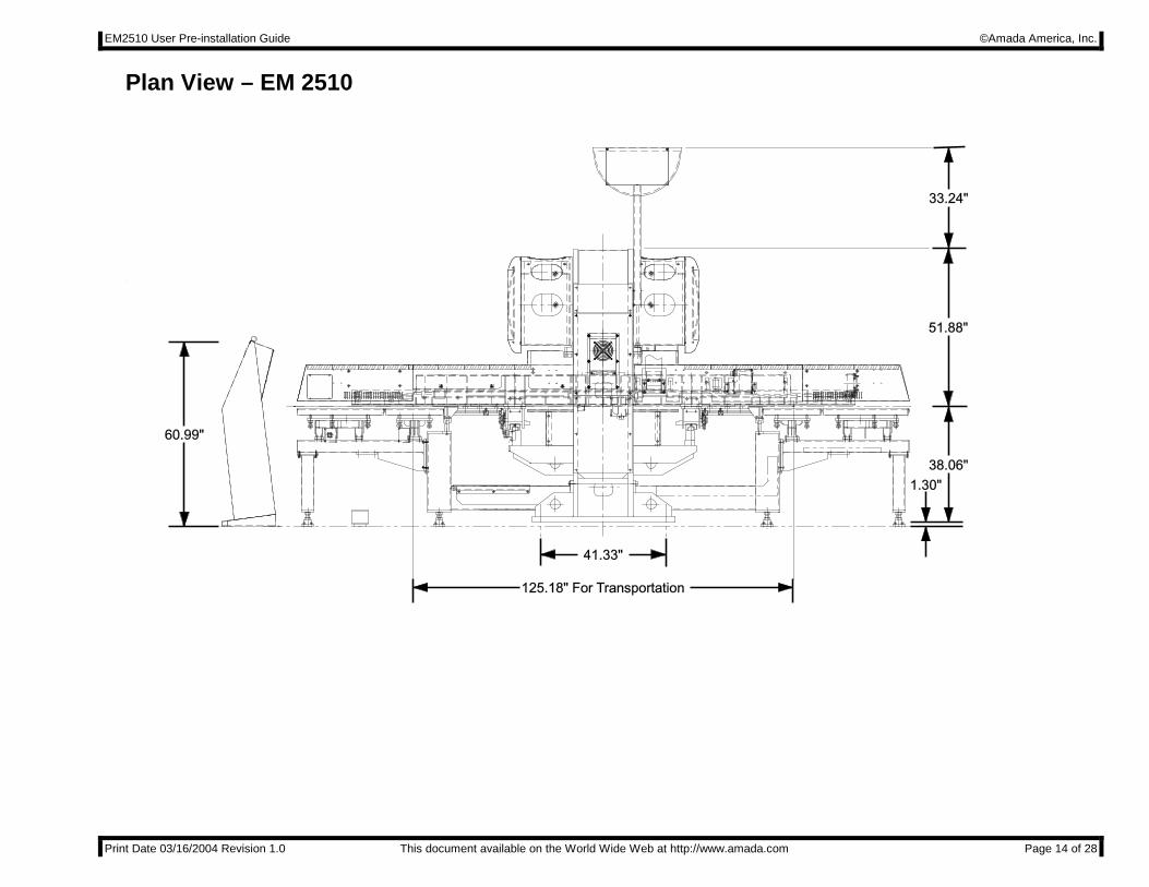
Plan View – EM 2510
M1
2X
35
M1
2X
35
M1
2X
35
M1
2X
35
M12X35 M12X35 M12X35 M12X35
41.33"
125.18" For Transportation
60.99"
1.30"38.06"
51.88"
33.24"
EM2510 User Pre-installation Guide ©Amada America, Inc.
Print Date 03/16/2004 Revision 1.0 This document available on the World Wide Web at http://www.amada.com Page 15 of 28
Foundation Requirements The EM2510 does not require a special foundation to perform as expected, however there are minimum requirements that an existing floor must meet in order to assure machine reliability and tool life. If the existing floor does not meet the following minimum requirements, plans for a recommended foundation are given in the section Foundation Anchoring Procedure of this document. The minimum acceptable floor conditions to assure a successful installation are: �� The area of the floor where the machine frame is to be located must be a single, homogeneous slab in good condition.
There must be no cracks or other signs of deterioration of the floor. �� The floor must be 4" to 6" thick. �� The floor must be capable of supporting 3.5 tons/ft². �� The floor must be level to 0.032"/ft. It is the customer’s responsibility to determine that the floor meets these minimum requirements. Placing the machine on an inadequate, cracked floor, or straddling seams in a floor may be grounds for voiding the machine warranty! If there is any question that the floor is not adequate, then a new machine location or new foundation must be considered. Amada America, Inc. does not recommend the use of vibration isolating mounts under the machine feet, as these devices have been shown to increase the vibration within the machine frame, increasing the likelihood of vibration related problems. Solid leveling devices are acceptable provided they incorporate a means of anchoring the machine to the floor.
Special Note: This document details several methods of anchoring the EM2510 to a new foundation or an existing floor. These methods are designed to install the EM2510 as a stand-alone machine using the “AY” base plates, which are included with the machine, or, installation using optional Amada Machine Mounts (Spherical Seat Wedge Mounts). Installation or use of additional options such as leveling pads or material handling systems may dictate other methods of anchoring or foundation design not shown in this document. Before committing to a specific method of anchoring the EM2510, confirm that the chosen method is compatible with all purchased optional items and planned expansion.
EM2510 User Pre-installation Guide ©Amada America, Inc.
Print Date 03/16/2004 Revision 1.0 This document available on the World Wide Web at http://www.amada.com Page 16 of 28
Foundation Anchoring Procedure An ideal foundation is given on the following pages. This foundation must be used if the existing floor cannot meet the minimum requirements to support the machine. The foundation must consist of a single, homogeneous slab. The foundation must be level to within 0.032" / ft. Anchoring the EM2510 to the floor using the anchor-bolts supplied is essential to ensure reliable performance. Amada generally recommends that the foundation have a minimum load bearing capacity of 3.5 ton/ft2. It is the purchaser’s responsibility to determine that the foundation meets these requirements. Please note the following: �� The machine is shipped with “AY Plates” for anchoring to the floor using customer supplied anchor bolts. �� A second method using optional Amada Machine Mounts (Spherical Seat Wedge Mounts) and epoxy anchor bolts is also
available. The Amada Machine mounts make achieving and maintaining the correct level of the machine easier and faster.

EM2510 User Pre-installation Guide ©Amada America, Inc.
Print Date 03/16/2004 Revision 1.0 This document available on the World Wide Web at http://www.amada.com Page 17 of 28
Ideal Foundation Plan View
Machine Centerline
Existing Floor
Existing Floor
New Foundation
36."Machine Foot Bolt Centerline
Machine Foot Bolt Centerline
188"
72"
36."116.34"
41.34"
20.67"
144"
12 - Anchor Bolts - 0.5" Dia. x 5" Supplied by Customer
"AY" Plates (4)
Ideal Foundation Elevation View
Floorline
116.4"
24"
12"
Cement
Crushed Stone

EM2510 User Pre-installation Guide ©Amada America, Inc.
Print Date 03/16/2004 Revision 1.0 This document available on the World Wide Web at http://www.amada.com Page 18 of 28
Alternative Anchoring Method (Amada Machine Mounts with Drilled Hole, Anchor Rod and Adhesive) This machine mounting method should be used with the optional Amada Machine mounts (Spherical Seat Wedge Mounts). Alternative Floor Bolt Mounting Method Plan View:
Machine Centerline
41.34" Main Frame Anchor Hole LocationCenterpoint of 1 1/8" drilled hole
20.67"
116.34" Main Frame Anchor Hole LocationCenterpoint of 1 1/8" drilled hole
Floor Line
Machine Foot
Machine Frame
Machine Foot
1" x 16" anchor bolt
Sperical Seat Wedge Mount (Amada Machine Mounts)
5.5"
6.00"

EM2510 User Pre-installation Guide ©Amada America, Inc.
Print Date 03/16/2004 Revision 1.0 This document available on the World Wide Web at http://www.amada.com Page 19 of 28
Drilled Hole with Anchor Rod and Adhesive Mounting Procedure Step 1. Pre-Drill the four Anchor Rod holes in the existing floor prior to placing the
machine. The holes should be drilled approximately 6” deep. See Alternative Floor Bolt Mounting Method Plan View (Drilled Hole with Adhesive Anchor Rod) for correct layout dimensions. Existing Floor
Step 2. Set the Amada Machine Leveling pads over the drilled holes
Existing Floor
Step 3. Set the machine on the machine leveling plates.
Existing Floor
Step 4 Level the machine frame by adjusting the Amada machine leveling pads.
See Leveling the Machine section for correct procedure.

EM2510 User Pre-installation Guide ©Amada America, Inc.
Print Date 03/16/2004 Revision 1.0 This document available on the World Wide Web at http://www.amada.com Page 20 of 28
Step 5 Fill each of the Anchor Rod holes to within 2 inches of the floor surface with the Adhesive compound. Do not overfill.
Existing Floor
Step 6 Attach the hex nut and flat washer on the Anchor Rod and place the
Anchor Rod into the drilled hole. Using a twisting motion to move the Anchor Rod through the epoxy compound, seat the flat washer and hex nut against the top of the machine foot.
Existing Floor
Step 7 Allow the Adhesive to harden for 24 hours.
Step 8. Tighten the 4 hex nuts.
Existing Floor
EM2510 User Pre-installation Guide ©Amada America, Inc.
Print Date 03/16/2004 Revision 1.0 This document available on the World Wide Web at http://www.amada.com Page 21 of 28
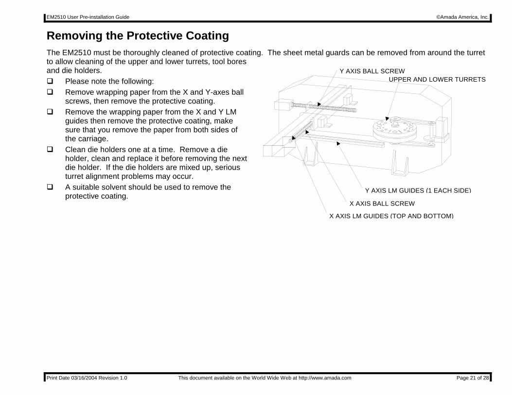
Y AXIS BALL SCREW
X AXIS BALL SCREW
Y AXIS LM GUIDES (1 EACH SIDE)
X AXIS LM GUIDES (TOP AND BOTTOM)
UPPER AND LOWER TURRETS
Removing the Protective Coating The EM2510 must be thoroughly cleaned of protective coating. The sheet metal guards can be removed from around the turret to allow cleaning of the upper and lower turrets, tool bores and die holders. �� Please note the following: �� Remove wrapping paper from the X and Y-axes ball
screws, then remove the protective coating. �� Remove the wrapping paper from the X and Y LM
guides then remove the protective coating, make sure that you remove the paper from both sides of the carriage.
�� Clean die holders one at a time. Remove a die holder, clean and replace it before removing the next die holder. If the die holders are mixed up, serious turret alignment problems may occur.
�� A suitable solvent should be used to remove the protective coating.
EM2510 User Pre-installation Guide ©Amada America, Inc.
Print Date 03/16/2004 Revision 1.0 This document available on the World Wide Web at http://www.amada.com Page 22 of 28
Machine Leveling Proper Machine leveling is critical to the EM2510 performing as designed.
Materials and tools required: Supplied with the machine:
Assorted thickness machine leveling shim stock Anchor bolts Supplied by Amada Service: Spirit level capable of reading 0.0005"/ft One (1) 12 ton hydraulic bottle jack
Not supplied: Additional shim stock of 0.005" thickness may be required to achieve a properly leveled machine.
EM2510 User Pre-installation Guide ©Amada America, Inc.
Print Date 03/16/2004 Revision 1.0 This document available on the World Wide Web at http://www.amada.com Page 23 of 28
Rocking Test After the machine frame has been leveled the use of the following G-code is necessary to determine that the machine frame is properly leveled and balanced. Should the machine frame vibrate or move excessively during the rocking test the machine frame must be re-leveled using the procedure in this manual. Should the proper leveling technique not eliminate the excessive frame motion, consideration must be given to relocation of the machine or replacement of the existing floor with an adequate foundation.
Repeat test with X-axis movement values of 0.500", 1.000", and 4.000" G92X98.425Y50. G06A.100B0 N1 G91G70X-.25Tttt(Use any valid tool number) G70X.25 M97P1 G50
EM2510 User Pre-installation Guide ©Amada America, Inc.
Print Date 03/16/2004 Revision 1.0 This document available on the World Wide Web at http://www.amada.com Page 24 of 28
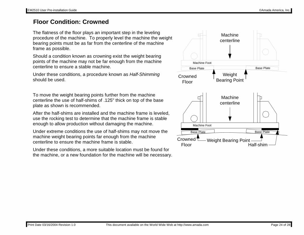
Floor Condition: Crowned The flatness of the floor plays an important step in the leveling procedure of the machine. To properly level the machine the weight bearing points must be as far from the centerline of the machine frame as possible. Should a condition known as crowning exist the weight bearing points of the machine may not be far enough from the machine centerline to ensure a stable machine. Under these conditions, a procedure known as Half-Shimming should be used.
CrownedFloor
WeightBearing Point
Machinecenterline
Base Plate Base Plate
Machine Foot
To move the weight bearing points further from the machine centerline the use of half-shims of .125" thick on top of the base plate as shown is recommended. After the half-shims are installed and the machine frame is leveled, use the rocking test to determine that the machine frame is stable enough to allow production without damaging the machine. Under extreme conditions the use of half-shims may not move the machine weight bearing points far enough from the machine centerline to ensure the machine frame is stable. Under these conditions, a more suitable location must be found for the machine, or a new foundation for the machine will be necessary.
CrownedFloor
Weight Bearing Point
Machinecenterline
Half-shim
Base Plate Base Plate
Machine Foot

EM2510 User Pre-installation Guide ©Amada America, Inc.
Print Date 03/16/2004 Revision 1.0 This document available on the World Wide Web at http://www.amada.com Page 25 of 28
Floor Condition: Sloped The slope of the floor plays an important step in the leveling procedure of the machine. To properly level the machine the weight bearing points must be as far from the centerline of the machine frame as possible. Should the floor slope excessively the weight bearing points of the machine may not be far enough from the machine centerline to ensure a stable machine. Under these conditions, a procedure known as Half-Shimming should be used.
Sloped FloorWeight Bearing Point
Machinecenterline
Shim
Base PlateBase Plate
Machine Foot
To move the weight bearing points further from the machine centerline the use of half-shims of .125" thick on top of the base plate and leveling shims as shown is recommended. After the half-shims are installed and the machine frame is leveled, use the rocking test to determine that the machine frame is stable enough to allow production without damaging the machine. Under extreme conditions the use of half-shims may not move the machine weight bearing points far enough from the machine centerline to ensure the machine frame is stable. Under these conditions a more suitable location must be found for the machine, or a new foundation for the machine will be necessary.
Sloped FloorWeight Bearing Point
Machinecenterline
Base PlateBase Plate
Machine Foot
Half-shim
Shim
EM2510 User Pre-installation Guide ©Amada America, Inc.
Print Date 03/16/2004 Revision 1.0 This document available on the World Wide Web at http://www.amada.com Page 26 of 28
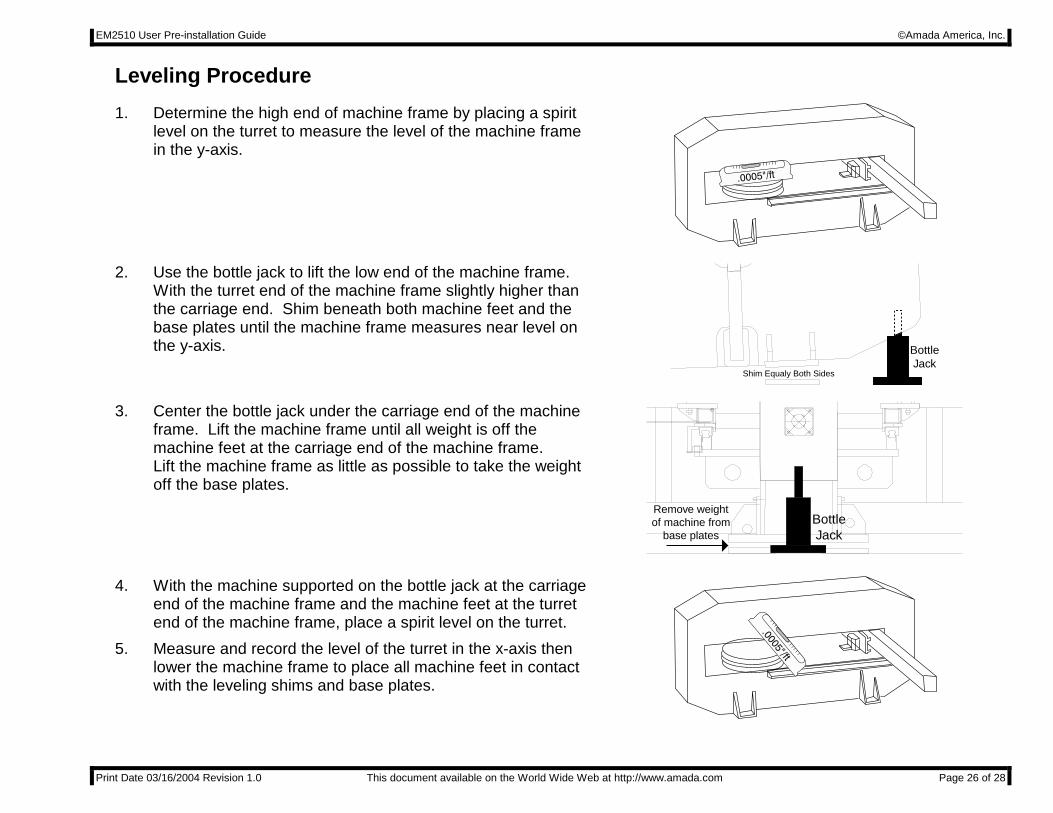
Leveling Procedure 1. Determine the high end of machine frame by placing a spirit
level on the turret to measure the level of the machine frame in the y-axis.
2. Use the bottle jack to lift the low end of the machine frame. With the turret end of the machine frame slightly higher than the carriage end. Shim beneath both machine feet and the base plates until the machine frame measures near level on the y-axis.
Shim Equaly Both Sides
BottleJack
3. Center the bottle jack under the carriage end of the machine frame. Lift the machine frame until all weight is off the machine feet at the carriage end of the machine frame. Lift the machine frame as little as possible to take the weight off the base plates.
Remove weightof machine from
base platesBottleJack
4. With the machine supported on the bottle jack at the carriage end of the machine frame and the machine feet at the turret end of the machine frame, place a spirit level on the turret.
5. Measure and record the level of the turret in the x-axis then lower the machine frame to place all machine feet in contact with the leveling shims and base plates.

EM2510 User Pre-installation Guide ©Amada America, Inc.
Print Date 03/16/2004 Revision 1.0 This document available on the World Wide Web at http://www.amada.com Page 27 of 28
6. Lift the turret end of the machine frame to allow shimming between the machine feet and base plates to level the machine frame in the x-axis.
7. Repeat steps 3 to 5 until the machine frame measures level to 0.0005"/ft in step 5, then continue.
Shim tolevel X-axis
BottleJack
8. With the weight of the carriage end of the machine supported by the bottle jack. Monitor the level of the turret in the x-axis, as the bottle jack is slowly lowered to place the carriage end machine feet in contact with the base plates. Any change in the level indicates that the carriage end of the machine needs to be leveled. Remove weight
of machine frombase plates
BottleJack
9. Lift the carriage end of the machine frame to allow shimming between the machine feet and base plates to level the carriage end of the machine frame in the x-axis direction.
10. Repeat steps 8 and 9 until no difference in level is noted when the machine weight is on or off of the base plates and shims, then continue. Shim to
level X-axis
BottleJack
11. With all of the machine feet setting on the shims and base plates place the spirit level on the turret to measure and note the level of the machine frame in the y-axis.

EM2510 User Pre-installation Guide ©Amada America, Inc.
Print Date 03/16/2004 Revision 1.0 This document available on the World Wide Web at http://www.amada.com Page 28 of 28
12. Using the bottle jack lift the low end of the machine frame and shim equally under both machine feet to level the machine frame in the y-axis.
13. Repeat step 11 to 12 until the machine frame measures level to 0.0005"/ft in the y-axis then continue.
Shim Equaly Both Sides
BottleJack
14. Run the machine using the rocking test G-code to determine that the machine frame is leveled adequately. Should excessive movement of the machine frame be noticed check for the conditions discussed in Floor Condition Crowned and Floor Condition Sloped.
15. Tighten the anchor bolt nuts to prevent the machine frame from moving when in use. Monitor the machine level while tightening the anchor bolts to assure the machine level is not changed.