EM MultiV5 OutdoorUnits 01 17 - DMG · PDF fileMULTI V 5 Outdoor Unit Engineering Manual ......
100
ENGINEERING MANUAL Variable Refrigerant Flow Outdoor Units 6.0 to 42.0 Tons
Transcript of EM MultiV5 OutdoorUnits 01 17 - DMG · PDF fileMULTI V 5 Outdoor Unit Engineering Manual ......

ENGINEERING MANUAL
Variable Refrigerant Flow Outdoor Units6.0 to 42.0 Tons

For continual product development, LG Electronics U.S.A., Inc. reserves the right to change specifications without notice. © LG Electronics U.S.A., Inc.
This document, as well as all reports, illustrations, data, information, and other materials are the property of LG Electronics U.S.A., Inc., and are
disclosed by LG Electronics U.S.A., Inc. only in confidence. This document is for design purposes only.
A summary list of safety precautions is on page 3.
To access additional technical documentation such as submittals, indoor unit engineering manuals, installation, service, product data performance, general best practice, and building ventilation manuals, as well as white
papers, catalogs, LATS software programs, and more, log in to www.lghvac.com.
PROPRIETARY DATA NOTICE
TABLE OF CONTENTS
TABLE OF SYMBOLS
DANGER This symbol indicates an imminently hazardous situation which, if not avoided, will result in death or serious injury.
WARNING This symbol indicates a potentially hazardous situation which, if not avoided, could result in death or serious injury.
CAUTION This symbol indicates a potentially hazardous situation which, if not avoided, may result in minor or moderate injury.
This symbol indicates situations that may result in equipment or property damage accidents only.
This symbol indicates an action that should not be performed.
Unit Nomenclature ........................................................................................................................................................................................ 4
LG Air Conditioner Technical Solution (LATS) ......................................................................................................................................... 5-6
Outdoor Unit Product Data ...................................................................................................................................................................... 7-71Mechanical Specifications ...................................................................................................................................................................... 9-10Features ................................................................................................................................................................................................... 10General Data ....................................................................................................................................................................................... 11-19Electrical Data ..................................................................................................................................................................................... 20-21Connection Limitations .............................................................................................................................................................................. 22Dimensions .......................................................................................................................................................................................... 23-24Wiring Diagrams .................................................................................................................................................................................. 25-32Refrigerant Flow Diagrams ................................................................................................................................................................... 33-58Acoustic Data ...................................................................................................................................................................................... 59-64Accessories ......................................................................................................................................................................................... 65-71
Heat Recovery Unit Product Data ......................................................................................................................................................... 72-80Mechanical Specifications ......................................................................................................................................................................... 73General Data ............................................................................................................................................................................................ 74Electrical Data .......................................................................................................................................................................................... 74Dimensions .......................................................................................................................................................................................... 75-77Wiring Diagram ......................................................................................................................................................................................... 78Refrigerant Flow Diagram ......................................................................................................................................................................... 79Accessories .............................................................................................................................................................................................. 80
Electrical Connections .......................................................................................................................................................................... 81-84System for Heat Pump Operation .............................................................................................................................................................. 82System for Heat Recovery Operation ........................................................................................................................................................ 83DIP Switch Settings For Use With Gen 4 Indoor Units ............................................................................................................................... 84
Placement Considerations .................................................................................................................................................................... 85-98Piping Limitations ................................................................................................................................................................................. 86-91Selecting the Best Location for Outdoor Unit(s) .................................................................................................................................... 92-93Outdoor Unit Clearance Requirements .......................................................................................................................................................94Installing Outdoor Units Indoors ........................................................................................................................................................... 95-96Selecting the Best Location / Clearance Requirements for Heat Recovery Unit(s) ................................................................................ 97-98

4 | INTRODUCTION
MU
LTI V
5 O
utdo
or U
nit E
ngin
eerin
g M
anua
l
©
Outdoor Units (ODU)
ARU M 072 B T 5
Generation5 = Fifth
Airflow ConfigurationT = Top Discharge
Electrical RatingsB = 208–230V/60Hz/3Ph D = 460V/60Hz/3Ph
Nominal Capacity (Nominal cooling capacity in Btu/h)
TypeM = Combination (Heat Pump or Heat Recovery)
FamilyARU = Multi V Outdoor Unit (Refrigerant R410A)
Heat Recovery Units (HRU)PRHR 02 2A
Series Number2A = Series Number
Number of Ports02 = Two Ports 03 = Three Ports 04 = Four Ports
FamilyPRHR = Multi V Heat Recovery (HR) unit (Refrigerant R410A)
072 = 72,000 096 = 96,000 121 = 121,000 144 = 144,000 168 = 168,000
192 = 192,000 216 = 216,000 241 = 240,000 264 = 264,000 288 = 288,000
312 = 312,000 336 = 336,000 360 = 360,000 384 = 384,000 408 = 408,000
432 = 432,000 456 = 456,000 480 = 480,000 504 = 504,000
UNIT NOMENCLATUREOutdoor Units and Heat Recovery Units
E
EfficiencyE = High Efficiency

INTRODUCTION | 5
Introduction
©
LG Air Conditioner Technical Solution (LATS) SoftwareA properly designed and installed refrigerant piping system is critical to the optimal performance of LG air-conditioning systems. To assist engineers, LG offers, free of charge, LG Air Conditioner Technical Solution (LATS) software—a total design solution for LG air conditioning systems.
To reduce the risk of designing an improper applied system or one that will not operate correctly, LG requires that LATS software be used on all projects.
FormatsLATS is available to LG customers in three user interfaces: LATS HVAC, LATS CAD2, and LATS REVIT. All three LATS formats are available through www.myLGHVAC.com, or contact an LG Sales Representative.
LATS HVAC is a Windows®-based application that aids engineers in designing LG Variable Refrigerant Flow (VRF), Multi F / Multi F MAX, Single-Zone, and Energy Recovery Ventilator (ERV) systems.*Windows® is a registered mark of Microsoft® Corporation.
LATS CAD2 combines the LG LATS program with AutoCAD® software**. It permits engineers to layout and validate LG Multi V Variable Refrigerant Flow (VRF), Multi F / Multi F MAX, Single-Zone, and Energy Recovery Ventilator (ERV) systems directly into CAD drawings.LATS Revit integrates the LG LATS program with Revit® software**. It permits engineers to layout and validate Multi V VRF systems directly into Revit drawings.**AutoCAD® and Revit® are both registered marks of Autodesk, Inc.
FeaturesAll LG product design criteria have been loaded into the program, making LATS simple to use: double click or drag and drop the com-ponent choices. Build systems in Tree Mode where the refrigerant system can be viewed. Switch to a Schematic diagram to see the electrical and communications wiring.LATS software permits the user to input region data, indoor and outdoor design temperatures, modify humidity default values, zoning, specify type and size outdoor units and indoor units, and input air flow and external static pressure (ESP) for ducted indoor units.
The program can also:
LG AIR CONDITIONER TECHNICAL SOLUTION (LATS)
• Import building loads from a separate Excel file.• Present options for outdoor unit auto selection.• Automatically calculate component capacity based on design
conditions for the chosen region.• Verify if the height differences between the various system
components are within system limits.• Provide the correct size of each refrigerant piping segment and LG
Y-Branches and Headers.
• Adjust overall piping system length when elbows are added.• Check for component piping limitations and flag if any parameters
are broken.• Factor operation and capacity for defrost operation.• Calculate refrigerant charge, noting any additional trim charge.• Suggest accessories for indoor units and outdoor units.• Run system simulation.
Features depend on which LATS program is being used, and the type of system being designed.
Figure 1: Example of LATS CAD2.

6 | INTRODUCTION
MU
LTI V
5 O
utdo
or U
nit E
ngin
eerin
g M
anua
l
©
LATS Generates a Complete Project ReportLATS software also generates a report containing project design parameters, cooling and heating design day system component perfor-mance, and capacity data. The report includes system combination ratio and refrigerant charge calculations; and provides detailed bill of material, including outdoor units, indoor units, control devices, accessories, refrigerant pipe sizes segregated by building, by system, by pipe size, and by pipe segments. LATS can generate an Excel GERP report that can imported into the LG SOPS pricing and ordering system.
Proper Design to Install ProcedureLG encourages a two report design-to-install-procedure. After the design engineer determines building / zone loads and other details, the engineer opens the LATS program and inputs the project’s infor-mation. When the design is complete, the “Auto Piping” and “System Check” functions should be used to verify piping sizes, limitations, and if any design errors are present. If errors are found, engineers should adjust the design, and run Auto Piping and System Check again. When the design passes the checks, then the engineer prints out a project “Shop Drawing” (LATS Tree Diagram) and provides it to the installing contractor. The contractor should follow the LATS Tree Diagram when building the piping system, but oftentimes the design changes on the building site:
• Architect has changed location and/or purpose of room(s).• Outdoor unit cannot be placed where originally intended.• Structural elements prevent routing the piping as planned.• Air conditioning system conflicts with other building systems
(plumbing, gas lines, etc.).
The contractor must mark any deviation from the design on the Shop Drawing, including as-built straight lines and elbows. This “Mark Up” drawing should be returned to the design engineer or Rep, who should input contractor changes into the LATS file. (Copy the original LATS software file, save and rename as a separate file, and modify all piping lengths by double-clicking on each length and editing information.) Like the shop drawing, the Auto Piping and System Check should also be run on this new “As Built” drawing. The design engineer or Rep must then provide the final As Built file to the contractor. The Mark Up version must be compared to the As Built version for:
• Differences in pipe diameter(s). If incorrect diameters have been installed, the piping must be changed out. If pipe diameters have changed,check to see if Y-Branches will also need to be changed.
• Changes to outdoor unit and indoor unit capacities. Capacities changes may impact line length changes.• Additional refrigerant charge quantity (“Trim Charge”). Trim charge will change if piping lengths and diameters change. The As Built version
must reflect installed piping lengths to ensure correct trim charge.
All documents submitted by the contractor, as well as the Shop Drawing and the As Built Drawing files must be provided for commissioning purposes. Model and serial numbers for all system components must also be submitted. If the steps previously detailed are not followed, and all documents are not provided to the commissioning agent, the project runs the risk of not being commissioned and voiding any limited warranty LG offers on the equipment.
LG AIR CONDITIONER TECHNICAL SOLUTION (LATS)
Figure 2: Example of a LATS Tree Diagram.

OUTDOOR UNIT PRODUCT DATAMechanical Specifications on page 9Features on page 10General Data on page 11Electrical Data on page 20Connection Limitations on page 22Dimensions on page 23Wiring Diagrams on page 25Refrigerant Flow Diagrams on page 33Acoustic Data on page 59Accessories on page 65

8 | ODU PRODUCT DATA
MU
LTI V
5 O
utdo
or U
nit E
ngin
eerin
g M
anua
l
©
Multi V 5 Outdoor Units
MECHANICAL SPECIFICATIONS
Multi V 5 Outdoor UnitsGeneralLG Multi V 5 Variable Refrigerant Flow (VRF) outdoor unit can be configured to operate as a Heat Pump system or a Heat Recovery System. Single, dual, or triple frame outdoor unit combinations are connected to indoor units with a single refrigerant piping system using factory designed and supplied Y-branches, Headers, and/or Heat Recovery Units and have integrated controls.The system is capable of being designed for minimum piping and maximum design flexibility. Each Heat Recovery Unit piping port is independently capable of operating in either heating or cooling mode regard-less of the mode of other piping ports on the same heat recovery unit or in the system. The Heat Recovery Unit is capable of changing mode of individual indoor units or zones (cooling to heating or heating to cooling) within a maximum time frame of three (3) minutes to ensure indoor temperature can be properly maintained. LG components are manufactured in a facility registered to ISO 9001 and ISO 14001, which is a set of standards applying to environmental protection set by the International Organization for Standardization (ISO). The units are Electrical Testing Laboratories (ETL) listed and bear the ETL label. All internal wiring is in accordance with the National Electrical Code (NEC).
Temperature RangesHeat Pump ConfigurationIn Heat Pump configuration, the system can operate in heating only mode (i.e. all indoor units in heating mode) from -13°F to 61°F outdoor ambient wet bulb. Heat Pump systems can operate in cooling mode from 5°F to 122°F outdoor ambient dry bulb. Optional low am-bient cooling kit extends the cooling only operating range (i.e., all indoor units in cooling mode) down to -9.9°F. See the Multi V 5 Installation Manual for DIP switch settings for Heat Pump operation.
Heat Recovery ConfigurationIn Heat Recovery configuration, the system can operate in heating only mode (i.e. all indoor units in heating mode) from -13°F to 61°F out-door ambient wet bulb. Heat Recovery systems can operate in cooling only mode from 5°F to 122°F outdoor ambient dry bulb. Optional low ambient cooling kit extends cooling only operation range (i.e. all indoor units in cooling mode) down to -9.9°F. Heat Recovery synchronous operation range is 14°F to 81°F outdoor ambient dry bulb. See the Multi V 5 Installation Manual for DIP switch settings for Heat Recovery operation.
Casing / FrameOutdoor units are constructed with galvanized steel, bonderized and finished with baked enamel paint. Each frame has a removable inspec-tion panel to allow access to service tool connections, DIP switches, auto addressing, and error codes. The entire front panel of the outdoor unit is removable for maintenance.Outdoor unit frames are completely factory assembled, piped and wired. Dual and triple frame outdoor units are field piped with factory designed and supplied outdoor unit Y-branch kits to manifold them together into a single refrigerant circuit.
Refrigerant SystemThe refrigeration system consists of a single refrigeration circuit and uses R410A refrigerant. The outdoor unit is provided with factory installed components, including a refrigerant strainer, check valves, oil separator, oil level sensor, accumulator, four-way reversing valves, electronically controlled expansion valve (EEV), high and low side charging ports, high pressure safety switch, service valves, and interconnecting piping. Also included is an integral subcooler assembly consisting of a double spiral tube-type subcooling heat exchanger and EEV providing modulation of up to 23ºF subcooling.
Compressors-
digitally controlled inverter-driven hermetic scroll compressors to modulate capacity (variable from 12 to 150Hz). An internal thermal over-load, and a factory-mounted 60 watt crankcase heater are included on all compressors.
Outdoor Unit CoilThe outdoor unit coils are of a nonferrous construction with louvered aluminum fins on copper tubing, and are protected by a metal guard. Coil fins have a factory applied corrosion resistant Black Fin™ and hydrophilic coating.

ODU PRODUCT DATA | 9
Outdoor U
nit Product D
ata
©
Multi V 5 Outdoor Units
MECHANICAL SPECIFICATIONS
Fans and MotorsAll outdoor unit frames <80MBh include one direct drive, variable speed, biomimetic enhanced, propeller type fan. All outdoor unit frames >80MBh include two direct drive, variable speed, biomimetic enhanced, propeller type fans.All fan motors have inherent protection, permanently lubricated bearings, and are variable speed with a maximum speed up to 1,150 rpm.Fan guards are provided to limit contact with moving parts. All Heat Pump / Heat Recovery outdoor units have vertical discharge airflow.Optional air guides can be field installed to change discharge airflow from vertical to horizontal.
ElectricalOutdoor units are available in 208-230V/60 Hz/3-phase or 460V/60 Hz/3-phase. The unit controls include current protection logic.
ControlsOutdoor units are factory wired with necessary electrical control components, integral microprocessors, printed circuit boards, thermistors, sensors, terminal blocks, and lugs for power wiring.The control circuit between the indoor units, heat recovery units, and outdoor unit is a variable low voltage DC communication completed using a two conductor, stranded, and shielded cable for the RS-485 daisy chain communication wiring.Microprocessor-based algorithms provide component protection, soft-start capability, refrigeration system pressure, temperature, defrost, and ambient control.
System FeaturesAdvanced Smart Load ControlAutomatically adjusts system target pressures based on outdoor temperature and humidity for increased cooling performance.
Intelligent HeatingBy monitoring the outdoor ambient humidity, the target high refrigerant pressure and compressor frequency can be reduced to extend heating operation, delay defrost operation initialization, and reduce power consumption.
HiPOR™ (High Pressure Oil Return)Refrigerant oil is captured from the compressor discharge by the centrifugal oil separator and then returned to the compressor through a separate oil injection pipe, preventing efficiency loss inherent in returning oil to the suction side of the compressor.
Smart Oil ControlActively monitors the oil level inside each compressor and only initiates an oil return cycle to flush oil in the piping system back to the com-pressor oil sump when the oil level is too low, preventing the need for timed oil return cycles while maintaining proper oil level.
Active Refrigerant ControlDepending on the operating mode and conditions, the system refrigerant level is automatically adjusted for increased part load and heating operation efficiency.
Variable Path Heat Exchanger
Vapor InjectionIn heating mode, warm refrigerant vapor discharged by the subcooling heat exchanger is injected into the compressor scroll chamber, im-proving heating performance at low outdoor ambient conditions.
Advanced PCB CoolingImproved cooling performance of the inverter drive control board by using liquid refrigerant instead of heat pipe or heat sink cooling methods using outdoor fan airflow.

10 | ODU PRODUCT DATA
MU
LTI V
5 O
utdo
or U
nit E
ngin
eerin
g M
anua
l
©
GENERAL DATA
Unit Model Number ARUM072BTE56.0 Ton
ARUM096BTE58.0 Ton
ARUM121BTE510.0 Ton
ARUM144BTE512.0 Ton
Individual Component Model Numbers - - - -Cooling PerformanceNominal Cooling Capacity (Btu/h)1 72,000 96,000 120,000 144,000Rated Cooling Capacity (Btu/h)2 69,000 92,000 114,000 138,000
Heating PerformanceNominal Heating Capacity (Btu/h)1 81,000 108,000 135,000 162,000Rated Heating Capacity (Btu/h)2 77,000 103,000 129,000 154,000
Operating RangeCooling (°F DB) 5 to 122 5 to 122 5 to 122 5 to 122Heating (°F WB) -13 to +61 -13 to +61 -13 to +61 -13 to +61Synchronous — Cooling Based (°F DB) 14 to 81 14 to 81 14 to 81 14 to 81Synchronous — Heating Based (°F WB) 14 to 61 14 to 61 14 to 61 14 to 61
CompressorInverter Quantity HSS DC Scroll x 1 HSS DC Scroll x 1 HSS DC Scroll x 1 HSS DC Scroll x 2Oil/Type PVE / FVC68D PVE / FVC68D PVE / FVC68D PVE / FVC68D
Fan (Top Discharge)Type Propeller (BLDC) Propeller (BLDC) Propeller (BLDC) Propeller (BLDC)Motor Output (kW) x Qty. 1.5 x 1 0.9 x 2 0.9 x 2 0.9 x 2Motor/Drive Brushless Digitally Controlled / Direct
Operating Range (RPM) Cooling 0 - 1,000 0 - 1,150 0 - 1,150 0 - 1,150Heating 80 - 1,000 80 - 1,150 80 - 1,150 80 - 1,150
Maximum Air Volume (CFM) 8,470 11,300 11,300 11,300Unit DataRefrigerant Type R410A R410A R410A R410ARefrigerant Control/Location EEV / Indoor Unit EEV / Indoor Unit EEV / Indoor Unit EEV / Indoor UnitFactory Charge lbs. of R410A 14.3 23.2 23.2 26.5Max. No. Indoor Units/System3 13 16 20 24Sound Pressure dB(A)4 58.0 58.0 59.0 60.0Net Unit Weight (lbs.) 430 507 507 639Shipping Weight (lbs.) 452 534 534 666Communication Cables5,6 2 x 18 2 x 18 2 x 18 2 x 18
Heat ExchangerMaterial and Fin Coating Copper Tube / Aluminum Fin and Black Coated Fin™ / HydrophilicRows/Fins per inch 2 / 17 2 / 17 2 / 17 3 / 17
Piping for Heat Recovery Operation7
Liquid Line Connection (in., OD) 3/8 Braze 3/8 Braze 1/2 Braze 1/2 BrazeLow Pressure Vapor Line Connection (in., OD) 3/4 Braze 7/8 Braze 1-1/8 Braze 1-1/8 BrazeHigh Pressure Vapor Line Connection (in., OD) 5/8 Braze 3/4 Braze 3/4 Braze 7/8 Braze
Piping for Heat Pump Operation7
Liquid Line Connection (in., OD) 3/8 Braze 3/8 Braze 1/2 Braze 1/2 BrazeVapor Line Connection (in., OD) 3/4 Braze 7/8 Braze 1-1/8 Braze 1-1/8 Braze
Table 1: Single Frame 208-230V Outdoor Units.
1Nominal capacity applied with non-ducted indoor units, and is rated 0 ft. above sea level with 25 ft. of refrigerant line per indoor unit and a 0 ft. level difference between outdoor and indoor units. All capaci-ties are net with a Combination Ratio between 95–105%. Nominal cooling capacity rating obtained with air entering the indoor unit at 80ºF dry bulb (DB) and 67ºF wet bulb (WB) and outdoor ambient conditions of 95ºF dry bulb (DB) and 75ºF wet bulb (WB). Nominal heating capacity rating obtained with air entering the indoor unit at 70ºF dry bulb (DB) and 59ºF wet bulb (WB) and outdoor ambient conditions of 47ºF dry bulb (DB) and 43ºF wet bulb (WB).2Rated capacity is certified under AHRI Standard 1230. See www.ahrinet.org for information.3The System Combination Ratio must be between 50–130%.4Sound pressure levels are tested in an anechoic chamber under ISO Standard 3745.
5Communication cable to be minimum 18 AWG, 2-conductor, stranded, shielded or unshielded, and must comply with applicable local and national codes. If shielded, ensure the communication cable is properly grounded to chassis at the master ODU only. Do not ground the ODU-IDU (or HRU) communication cable at any other point.6Power wiring is field provided, solid or stranded, and must comply with the applicable local and nation-al codes. See page 20 for detailed electrical data.7LG requires that LATS software be used on all projects to ensure correct line sizing. Designer must verify the shop drawing design against the as built design using LATS. Contractor must also use LG manufactured Y-Branch and Header Kits only.

ODU PRODUCT DATA | 11
Outdoor U
nit Product D
ata
©
GENERAL DATA
Table 2: Single Frame 208-230V Outdoor Units, continued.
Unit Model Number ARUM168BTE514.0 Ton
ARUM192BTE516.0 Ton
ARUM216BTE518.0 Ton
ARUM241BTE520.0 Ton
Individual Component Model Numbers - - - -Cooling PerformanceNominal Cooling Capacity (Btu/h)1 168,000 192,000 216,000 240,000Rated Cooling Capacity (Btu/h)2 160,000 184,000 206,000 222,000
Heating PerformanceNominal Heating Capacity (Btu/h)1 189,000 216,000 243,000 243,000Rated Heating Capacity (Btu/h)2 180,000 206,000 230,000 230,000
Operating RangeCooling (°F DB) 5 to 122 5 to 122 5 to 122 5 to 122Heating (°F WB) -13 to +61 -13 to +61 -13 to +61 -13 to +61Synchronous — Cooling Based (°F DB) 14 to 81 14 to 81 14 to 81 14 to 81Synchronous — Heating Based (°F WB) 14 to 61 14 to 61 14 to 61 14 to 61
CompressorInverter Quantity HSS DC Scroll x 2 HSS DC Scroll x 2 HSS DC Scroll x 2 HSS DC Scroll x 2Oil/Type PVE / FVC68D PVE / FVC68D PVE / FVC68D PVE / FVC68D
Fan (Top Discharge)Type Propeller (BLDC) Propeller (BLDC) Propeller (BLDC) Propeller (BLDC)Motor Output (kW) x Qty. 0.9 x 2 0.9 x 2 0.9 x 2 0.90 x 2Motor/Drive Brushless Digitally Controlled / Direct
Operating Range (RPM) Cooling 0 - 1,150 0 - 1,150 0 - 1,150 0 - 1,150Heating 80 - 1,150 80 - 1,150 80 - 1,150 80 - 1,150
Maximum Air Volume (CFM) 11,300 11,300 11,300 11,300Unit DataRefrigerant Type R410A R410A R410A R410ARefrigerant Control/Location EEV / Indoor Unit EEV / Indoor Unit EEV / Indoor Unit EEV / Indoor UnitFactory Charge lbs. of R410A 26.5 30.9 37.5 37.5Max. No. Indoor Units/System3 29 32 35 39Sound Pressure dB(A)4 61.0 62.0 64.0 65.0Net Unit Weight (lbs.) 639 659 666 666Shipping Weight (lbs.) 666 688 694 694Communication Cables5,6 2 x 18 2 x 18 2 x 18 2 x 18
Heat ExchangerMaterial and Fin Coating Copper Tube / Aluminum Fin and Black Coated Fin™ / HydrophilicRows/Fins per inch 3 / 17 3 / 17 3 / 17 3 / 17
Piping for Heat Recovery Operation7
Liquid Line Connection (in., OD) 5/8 Braze 5/8 Braze 5/8 Braze 5/8 BrazeLow Pressure Vapor Line Connection (in., OD) 1-1/8 Braze 1-1/8 Braze 1-1/8 Braze 1-3/8 BrazeHigh Pressure Vapor Line Connection (in., OD) 7/8 Braze 1-1/8 Braze 1-1/8 Braze 1-1/8 Braze
Piping for Heat Pump Operation7
Liquid Line Connection (in., OD) 5/8 Braze 5/8 Braze 5/8 Braze 5/8 BrazeVapor Line Connection (in., OD) 1-1/8 Braze 1-1/8 Braze 1-1/8 Braze 1-3/8 Braze
1Nominal capacity applied with non-ducted indoor units, and is rated 0 ft. above sea level with 25 ft. of refrigerant line per indoor unit and a 0 ft. level difference between outdoor and indoor units. All capaci-ties are net with a Combination Ratio between 95–105%. Nominal cooling capacity rating obtained with air entering the indoor unit at 80ºF dry bulb (DB) and 67ºF wet bulb (WB) and outdoor ambient conditions of 95ºF dry bulb (DB) and 75ºF wet bulb (WB). Nominal heating capacity rating obtained with air entering the indoor unit at 70ºF dry bulb (DB) and 59ºF wet bulb (WB) and outdoor ambient conditions of 47ºF dry bulb (DB) and 43ºF wet bulb (WB).2Rated capacity is certified under AHRI Standard 1230. See www.ahrinet.org for information.3The System Combination Ratio must be between 50–130%.4Sound pressure levels are tested in an anechoic chamber under ISO Standard 3745.
5Communication cable to be minimum 18 AWG, 2-conductor, stranded, shielded or unshielded, and must comply with applicable local and national codes. If shielded, ensure the communication cable is properly grounded to chassis at the master ODU only. Do not ground the ODU-IDU (or HRU) communication cable at any other point.6Power wiring is field provided, solid or stranded, and must comply with the applicable local and nation-al codes. See page 20 for detailed electrical data.7LG requires that LATS software be used on all projects to ensure correct line sizing. Designer must verify the shop drawing design against the as built design using LATS. Contractor must also use LG manufactured Y-Branch and Header Kits only.

12 | ODU PRODUCT DATA
MU
LTI V
5 O
utdo
or U
nit E
ngin
eerin
g M
anua
l
©
Unit Model Number ARUM264BTE522.0 Ton
ARUM288BTE524.0 Ton
ARUM312BTE526.0 Ton
ARUM336BTE528.0 Ton
Individual Component Model Numbers ARUM096BTE5 + ARUM168BTE5
ARUM096BTE5 + ARUM192BTE5
ARUM096BTE5 + ARUM216BTE5
ARUM121BTE5 + ARUM216BTE5
Cooling PerformanceNominal Cooling Capacity (Btu/h)1 264,000 288,000 312,000 336,000Rated Cooling Capacity (Btu/h)2 252,000 276,000 298,000 320,000
Heating PerformanceNominal Heating Capacity (Btu/h)1 297,000 324,000 351,000 378,000Rated Heating Capacity (Btu/h)2 283,000 309,000 333,000 359,000
Operating RangeCooling (°F DB) 5 to 122 5 to 122 5 to 122 5 to 122Heating (°F WB) -13 to +61 -13 to +61 -13 to +61 -13 to +61Synchronous — Cooling Based (°F DB) 14 to 81 14 to 81 14 to 81 14 to 81Synchronous — Heating Based (°F WB) 14 to 61 14 to 61 14 to 61 14 to 61
CompressorInverter Quantity HSS DC Scroll x 3 HSS DC Scroll x 3 HSS DC Scroll x 3 HSS DC Scroll x 3Oil/Type PVE / FVC68D PVE / FVC68D PVE / FVC68D PVE / FVC68D
Fan (Top Discharge)Type Propeller (BLDC) Propeller (BLDC) Propeller (BLDC) Propeller (BLDC)Motor Output (kW) x Qty. 0.90 x 2 + 0.90 x 2 0.90 x 2 + 0.90 x 2 0.90 x 2 + 0.90 x 2 0.90 x 2 + 0.90 x 2Motor/Drive Brushless Digitally Controlled / Direct
Operating Range (RPM) Cooling 0 - 1,150 0 - 1,150 0 - 1,150 0 - 1,150Heating 80 - 1,150 80 - 1,150 80 - 1,150 80 - 1,150
Maximum Air Volume (CFM) 22,600 22,600 22,600 22,600Unit DataRefrigerant Type R410A R410A R410A R410ARefrigerant Control/Location EEV / Indoor Unit EEV / Indoor Unit EEV / Indoor Unit EEV / Indoor UnitFactory Charge lbs. of R410A 23.2 + 26.5 23.2 + 30.9 23.2 + 37.5 23.2 + 37.5Max. No. Indoor Units/System3 42 45 52 55Sound Pressure dB(A)4 63.0 63.0 65.0 65.0Net Unit Weight (lbs.) 507 + 639 507 + 659 507 + 666 507 + 666Shipping Weight (lbs.) 534 + 666 534 + 688 534 + 694 534 + 694Communication Cables5,6 2 x 18 2 x 18 2 x 18 2 x 18
Heat ExchangerMaterial and Fin Coating Copper Tube / Aluminum Fin and Black Coated Fin™ / HydrophilicRows/Fins per inch 2 / 17 + 3 / 17 2 / 17 + 3 / 17 2 / 17 + 3 / 17 2 / 17 + 3 / 17
Piping for Heat Recovery Operation7
Liquid Line Connection (in., OD) 3/8 & 5/8 Braze 3/8 & 5/8 Braze 3/8 & 5/8 Braze 1/2 & 5/8 BrazeLow Pressure Vapor Line Connection (in., OD) 7/8 & 1-1/8 Braze 7/8 & 1-1/8 Braze 7/8 & 1-1/8 Braze 1-1/8 & 1-1/8 BrazeHigh Pressure Vapor Line Connection (in., OD) 3/4 & 7/8 Braze 3/4 & 1-1/8 Braze 3/4 & 1-1/8 Braze 3/4 & 1-1/8 Braze
Piping for Heat Pump Operation7
Liquid Line Connection (in., OD) 3/8 & 5/8 Braze 3/8 & 5/8 Braze 3/8 & 5/8 Braze 1/2 & 5/8 BrazeVapor Line Connection (in., OD) 7/8 & 1-1/8 Braze 7/8 & 1-1/8 Braze 7/8 & 1-1/8 Braze 1-1/8 & 1-1/8 Braze
Table 3: Dual Frame 208-230V Outdoor Units.
GENERAL DATA
1Nominal capacity applied with non-ducted indoor units, and is rated 0 ft. above sea level with 25 ft. of refrigerant line per indoor unit and a 0 ft. level difference between outdoor and indoor units. All capaci-ties are net with a Combination Ratio between 95–105%. Nominal cooling capacity rating obtained with air entering the indoor unit at 80ºF dry bulb (DB) and 67ºF wet bulb (WB) and outdoor ambient conditions of 95ºF dry bulb (DB) and 75ºF wet bulb (WB). Nominal heating capacity rating obtained with air entering the indoor unit at 70ºF dry bulb (DB) and 59ºF wet bulb (WB) and outdoor ambient conditions of 47ºF dry bulb (DB) and 43ºF wet bulb (WB).2Rated capacity is certified under AHRI Standard 1230. See www.ahrinet.org for information.3The System Combination Ratio must be between 50–130%.4Sound pressure levels are tested in an anechoic chamber under ISO Standard 3745.
5Communication cable to be minimum 18 AWG, 2-conductor, stranded, shielded or unshielded, and must comply with applicable local and national codes. If shielded, ensure the communication cable is properly grounded to chassis at the master ODU only. Do not ground the ODU-IDU (or HRU) communication cable at any other point.6Power wiring is field provided, solid or stranded, and must comply with the applicable local and nation-al codes. See page 20 for detailed electrical data.7LG requires that LATS software be used on all projects to ensure correct line sizing. Designer must verify the shop drawing design against the as built design using LATS. Contractor must also use LG manufactured Y-Branch and Header Kits only.

ODU PRODUCT DATA | 13
Outdoor U
nit Product D
ata
©
GENERAL DATA
Combination Unit Model Number ARUM360BTE530.0 Ton
ARUM384BTE532.0 Ton
ARUM408BTE534.0 Ton
Individual Component Model Numbers ARUM144BTE5 + ARUM216BTE5
ARUM168BTE5 + ARUM216BTE5
ARUM192BTE5 + ARUM216BTE5
Cooling PerformanceNominal Cooling Capacity (Btu/h)1 360,000 384,000 408,000Rated Cooling Capacity (Btu/h)2 344,000 366,000 390,000
Heating PerformanceNominal Heating Capacity (Btu/h)1 405,000 432,000 459,000Rated Heating Capacity (Btu/h)2 384,000 410,000 436,000
Operating RangeCooling (°F DB) 5 to 122 5 to 122 5 to 122Heating (°F WB) -13 to +61 -13 to +61 -13 to +61Synchronous — Cooling Based (°F DB) 14 to 81 14 to 81 14 to 81Synchronous — Heating Based (°F WB) 14 to 61 14 to 61 14 to 61
CompressorInverter Quantity HSS DC Scroll x 4 HSS DC Scroll x 4 HSS DC Scroll x 4Oil/Type PVE / FVC68D PVE / FVC68D PVE / FVC68D
Fan (Top Discharge)Type Propeller (BLDC) Propeller (BLDC) Propeller (BLDC)Motor Output (kW) x Qty. 0.90 x 2 + 0.90 x 2 0.90 x 2 + 0.90 x 2 0.90 x 2 + 0.90 x 2Motor/Drive Brushless Digitally Controlled / Direct
Operating Range (RPM) Cooling 0 - 1,150 0 - 1,150 0 - 1,150Heating 80 - 1,150 80 - 1,150 80 - 1,150
Maximum Air Volume (CFM) 22,600 22,600 22,600Unit DataRefrigerant Type R410A R410A R410ARefrigerant Control/Location EEV / Indoor Unit EEV / Indoor Unit EEV / Indoor UnitFactory Charge lbs. of R410A 26.5 + 37.5 26.5 + 37.5 30.9 + 37.5Max. No. Indoor Units/System3 58 61 64Sound Pressure dB(A)4 66.0 66.0 66.0Net Unit Weight (lbs.) 639 + 666 639 + 666 659 + 666Shipping Weight (lbs.) 666 + 694 666 + 694 688 + 694Communication Cables5,6 2 x 18 2 x 18 2 x 18
Heat ExchangerMaterial and Fin Coating Copper Tube / Aluminum Fin and Black Coated Fin™ / HydrophilicRows/Fins per inch 3 / 17 x 2 3 / 17 x 2 3 / 17 x 2
Piping for Heat Recovery Operation7
Liquid Line Connection (in., OD) 1/2 & 5/8 Braze 5/8 & 5/8 Braze 5/8 & 5/8 BrazeLow Pressure Vapor Line Connection (in., OD) 1-1/8 & 1-1/8 Braze 1-1/8 & 1-1/8 Braze 1-1/8 & 1-1/8 BrazeHigh Pressure Vapor Line Connection (in., OD) 7/8 & 1-1/8 Braze 7/8 & 1-1/8 Braze 1-1/8 & 1-1/8 Braze
Piping for Heat Pump Operation7
Liquid Line Connection (in., OD) 1/2 & 5/8 Braze 5/8 & 5/8 Braze 5/8 & 5/8 BrazeVapor Line Connection (in., OD) 1-1/8 & 1-1/8 Braze 1-1/8 & 1-1/8 Braze 1-1/8 & 1-1/8 Braze
Table 4: Dual Frame 208-230V Outdoor Units, continued.
1Nominal capacity applied with non-ducted indoor units, and is rated 0 ft. above sea level with 25 ft. of refrigerant line per indoor unit and a 0 ft. level difference between outdoor and indoor units. All capaci-ties are net with a Combination Ratio between 95–105%. Nominal cooling capacity rating obtained with air entering the indoor unit at 80ºF dry bulb (DB) and 67ºF wet bulb (WB) and outdoor ambient conditions of 95ºF dry bulb (DB) and 75ºF wet bulb (WB). Nominal heating capacity rating obtained with air entering the indoor unit at 70ºF dry bulb (DB) and 59ºF wet bulb (WB) and outdoor ambient conditions of 47ºF dry bulb (DB) and 43ºF wet bulb (WB).2Rated capacity is certified under AHRI Standard 1230. See www.ahrinet.org for information.3The System Combination Ratio must be between 50–130%.4Sound pressure levels are tested in an anechoic chamber under ISO Standard 3745.
5Communication cable to be minimum 18 AWG, 2-conductor, stranded, shielded or unshielded, and must comply with applicable local and national codes. If shielded, ensure the communication cable is properly grounded to chassis at the master ODU only. Do not ground the ODU-IDU (or HRU) communication cable at any other point.6Power wiring is field provided, solid or stranded, and must comply with the applicable local and nation-al codes. See page 20 for detailed electrical data.7LG requires that LATS software be used on all projects to ensure correct line sizing. Designer must verify the shop drawing design against the as built design using LATS. Contractor must also use LG manufactured Y-Branch and Header Kits only.

14 | ODU PRODUCT DATA
MU
LTI V
5 O
utdo
or U
nit E
ngin
eerin
g M
anua
l
©
Combination Unit Model Number ARUM432BTE536.0 Ton
ARUM456BTE538.0 Ton
ARUM480BTE540.0 Ton
ARUM504BTE542.0 Ton
Individual Component Model NumbersARUM121BTE5 +ARUM121BTE5 +ARUM192BTE5
ARUM121BTE5 + ARUM121BTE5 +ARUM216BTE5
ARUM121BTE5 + ARUM144BTE5 +ARUM216BTE5
ARUM121BTE5 +ARUM168BTE5 +ARUM216BTE5
Cooling PerformanceNominal Cooling Capacity (Btu/h)1 432,000 456,000 480,000 504,000Rated Cooling Capacity (Btu/h)2 412,000 434,000 458,000 480,000
Heating PerformanceNominal Heating Capacity (Btu/h)1 486,000 513,000 540,000 567,000Rated Heating Capacity (Btu/h)2 460,000 488,000 513,000 539,000
Operating RangeCooling (°F DB) 5 to 122 5 to 122 5 to 122 5 to 122Heating (°F WB) -13 to +61 -13 to +61 -13 to +61 -13 to +61Synchronous — Cooling Based (°F DB) 14 to 81 14 to 81 14 to 81 14 to 81Synchronous — Heating Based (°F WB) 14 to 61 14 to 61 14 to 61 14 to 61
CompressorInverter Quantity HSS DC Scroll x 4 HSS DC Scroll x 4 HSS DC Scroll x 5 HSS DC Scroll x 5Oil/Type PVE / FVC68D PVE / FVC68D PVE / FVC68D PVE / FVC68D
Fan (Top Discharge)Type Propeller (BLDC) Propeller (BLDC) Propeller (BLDC) Propeller (BLDC)Motor Output (kW) x Qty. 0.90x2 + 0.90x2 + 0.90x2 0.90x2 + 0.90x2 + 0.90x2 0.90x2 + 0.90x2 + 0.90x2 0.90x2 + 0.90x2 + 0.90x2Motor/Drive Brushless Digitally Controlled / Direct
Operating Range (RPM) Cooling 0 - 1,150 0 - 1,150 0 - 1,150 0 - 1,150Heating 80 - 1,150 80 - 1,150 80 - 1,150 80 - 1,150
Maximum Air Volume (CFM) 33,900 33,900 33,900 33,900Unit DataRefrigerant Type R410A R410A R410A R410ARefrigerant Control/Location EEV / Indoor Unit EEV / Indoor Unit EEV / Indoor Unit EEV / Indoor UnitFactory Charge lbs. of R410A 23.2 + 23.2 + 30.9 23.2 + 23.2 + 37.5 23.2 + 26.5 + 37.5 23.2 + 26.5 + 37.5Max. No. Indoor Units/System3 64 64 64 64Sound Pressure dB(A)4 66.0 66.0 67.0 67.0Net Unit Weight (lbs.) 507 + 507 + 659 507 + 507 + 666 507 + 639 + 666 507 + 639 + 666Shipping Weight (lbs.) 534 + 534 + 688 534 + 534 + 694 534 + 666 + 694 534 + 666 + 694Communication Cables5,6 2 x 18 2 x 18 2 x 18 2 x 18
Heat ExchangerMaterial and Fin Coating Copper Tube / Aluminum Fin and Black Coated Fin™ / HydrophilicRows/Fins per inch 2/17 x 2 + 3/17 2 / 17 x 2 + 3 / 17 2 / 17 + 3 / 17 x 2 2 / 17 + 3 / 17 x 2
Piping for Heat Recovery Operation7
Liquid Line Connection (in., OD) 1/2 & 1/2 & 5/8 Braze 1/2 & 1/2 & 5/8 Braze 1/2 & 1/2 & 5/8 Braze 1/2 & 5/8 & 5/8 BrazeLow Pressure Vapor Line Conn. (in., OD) 1-1/8 & 1-1/8 & 1-1/8 Braze 1-1/8 & 1-1/8 & 1-1/8 Braze 1-1/8 & 1-1/8 & 1-1/8 Braze 1-1/8 & 1-1/8 & 1-1/8 BrazeHigh Pressure Vapor Line Conn. (in., OD) 3/4 & 3/4 & 1-1/8 Braze 3/4 & 3/4 & 1-1/8 Braze 3/4 & 7/8 & 1-1/8 Braze 3/4 & 7/8 & 1-1/8 Braze
Piping for Heat Pump Operation7
Liquid Line Connection (in., OD) 1/2 + 1/2 + 5/8 Braze 1/2 & 1/2 & 5/8 Braze 1/2 & 1/2 & 5/8 Braze 1/2 & 5/8 & 5/8 BrazeVapor Line Connection (in., OD) 1-1/8 & 1-1/8 & 1-1/8 Braze 1-1/8 & 1-1/8 & 1-1/8 Braze 1-1/8 & 1-1/8 & 1-1/8 Braze 1-1/8 & 1-1/8 & 1-1/8 Braze
Table 5: Triple Frame 208-230V Outdoor Units.
GENERAL DATA
1Nominal capacity applied with non-ducted indoor units, and is rated 0 ft. above sea level with 25 ft. of refrigerant line per indoor unit and a 0 ft. level difference between outdoor and indoor units. All capaci-ties are net with a Combination Ratio between 95–105%. Nominal cooling capacity rating obtained with air entering the indoor unit at 80ºF dry bulb (DB) and 67ºF wet bulb (WB) and outdoor ambient conditions of 95ºF dry bulb (DB) and 75ºF wet bulb (WB). Nominal heating capacity rating obtained with air entering the indoor unit at 70ºF dry bulb (DB) and 59ºF wet bulb (WB) and outdoor ambient conditions of 47ºF dry bulb (DB) and 43ºF wet bulb (WB).2Rated capacity is certified under AHRI Standard 1230. See www.ahrinet.org for information.3The System Combination Ratio must be between 50–130%.4Sound pressure levels are tested in an anechoic chamber under ISO Standard 3745.
5Communication cable to be minimum 18 AWG, 2-conductor, stranded, shielded or unshielded, and must comply with applicable local and national codes. If shielded, ensure the communication cable is properly grounded to chassis at the master ODU only. Do not ground the ODU-IDU (or HRU) communication cable at any other point.6Power wiring is field provided, solid or stranded, and must comply with the applicable local and nation-al codes. See page 20 for detailed electrical data.7LG requires that LATS software be used on all projects to ensure correct line sizing. Designer must verify the shop drawing design against the as built design using LATS. Contractor must also use LG manufactured Y-Branch and Header Kits only.

ODU PRODUCT DATA | 15
Outdoor U
nit Product D
ata
©
Unit Model Number ARUM072DTE56.0 Ton
ARUM096DTE58.0 Ton
ARUM121DTE510.0 Ton
ARUM144DTE512.0 Ton
Individual Component Model Numbers - - - -Cooling PerformanceNominal Cooling Capacity (Btu/h)1 72,000 96,000 120,000 144,000Rated Cooling Capacity (Btu/h)2 69,000 92,000 114,000 138,000
Heating PerformanceNominal Heating Capacity (Btu/h)1 81,000 108,000 135,000 162,000Rated Heating Capacity (Btu/h)2 77,000 103,000 129,000 154,000
Operating RangeCooling (°F DB) 5 to 122 5 to 122 5 to 122 5 to 122Heating (°F WB) -13 to +61 -13 to +61 -13 to +61 -13 to +61Synchronous — Cooling Based (°F DB) 14 to 81 14 to 81 14 to 81 14 to 81Synchronous — Heating Based (°F WB) 14 to 61 14 to 61 14 to 61 14 to 61
CompressorInverter Quantity HSS DC Scroll x 1 HSS DC Scroll x 1 HSS DC Scroll x 1 HSS DC Scroll x 2Oil/Type PVE / FVC68D PVE / FVC68D PVE / FVC68D PVE / FVC68D
Fan (Top Discharge)Type Propeller (BLDC) Propeller (BLDC) Propeller (BLDC) Propeller (BLDC)Motor Output (kW) x Qty. 1.2 x 1 0.9 x 2 0.9 x 2 0.9 x 2Motor/Drive Brushless Digitally Controlled / Direct
Operating Range (RPM) Cooling 0 - 1,000 0 - 1,150 0 - 1,150 0 - 1,150Heating 80 - 1,000 80 - 1,150 80 - 1,150 80 - 1,150
Maximum Air Volume (CFM) 8,470 11,300 11,300 11,300Unit DataRefrigerant Type R410A R410A R410A R410ARefrigerant Control/Location EEV / Indoor Unit EEV / Indoor Unit EEV / Indoor Unit EEV / Indoor UnitFactory Charge lbs. of R410A 14.3 23.2 23.2 26.5Max. No. Indoor Units/System3 13 16 20 24Sound Pressure dB(A)4 58.0 58.0 59.0 60.0Net Unit Weight (lbs.) 430 507 507 639Shipping Weight (lbs.) 452 534 534 666Communication Cables5,6 2 x 18 2 x 18 2 x 18 2 x 18
Heat ExchangerMaterial and Fin Coating Copper Tube / Aluminum Fin and Black Coated Fin™ / HydrophilicRows/Fins per inch 2 / 17 2 / 17 2 / 17 3 / 17
Piping for Heat Recovery Operation7
Liquid Line Connection (in., OD) 3/8 Braze 3/8 Braze 1/2 Braze 1/2 BrazeLow Pressure Vapor Line Connection (in., OD) 3/4 Braze 7/8 Braze 1-1/8 Braze 1-1/8 BrazeHigh Pressure Vapor Line Connection (in., OD) 5/8 Braze 3/4 Braze 3/4 Braze 7/8 Braze
Piping for Heat Pump Operation7
Liquid Line Connection (in., OD) 3/8 Braze 3/8 Braze 1/2 Braze 1/2 BrazeVapor Line Connection (in., OD) 3/4 Braze 7/8 Braze 1-1/8 Braze 1-1/8 Braze
GENERAL DATA
Table 6: Single Frame 460V Outdoor Units.
1Nominal capacity applied with non-ducted indoor units, and is rated 0 ft. above sea level with 25 ft. of refrigerant line per indoor unit and a 0 ft. level difference between outdoor and indoor units. All capaci-ties are net with a Combination Ratio between 95–105%. Nominal cooling capacity rating obtained with air entering the indoor unit at 80ºF dry bulb (DB) and 67ºF wet bulb (WB) and outdoor ambient conditions of 95ºF dry bulb (DB) and 75ºF wet bulb (WB). Nominal heating capacity rating obtained with air entering the indoor unit at 70ºF dry bulb (DB) and 59ºF wet bulb (WB) and outdoor ambient conditions of 47ºF dry bulb (DB) and 43ºF wet bulb (WB).2Rated capacity is certified under AHRI Standard 1230. See www.ahrinet.org for information.3The System Combination Ratio must be between 50–130%.4Sound pressure levels are tested in an anechoic chamber under ISO Standard 3745.
5Communication cable to be minimum 18 AWG, 2-conductor, stranded, shielded or unshielded, and must comply with applicable local and national codes. If shielded, ensure the communication cable is properly grounded to chassis at the master ODU only. Do not ground the ODU-IDU (or HRU) communication cable at any other point.6Power wiring is field provided, solid or stranded, and must comply with the applicable local and nation-al codes. See page 21 for detailed electrical data.7LG requires that LATS software be used on all projects to ensure correct line sizing. Designer must verify the shop drawing design against the as built design using LATS. Contractor must also use LG manufactured Y-Branch and Header Kits only.

16 | ODU PRODUCT DATA
MU
LTI V
5 O
utdo
or U
nit E
ngin
eerin
g M
anua
l
©
Unit Model Number ARUM168DTE514.0 Ton
ARUM192DTE516.0 Ton
ARUM216DTE518.0 Ton
ARUM241DTE520.0 Ton
Individual Component Model Numbers - - - -Cooling PerformanceNominal Cooling Capacity (Btu/h)1 168,000 192,000 216,000 240,000Rated Cooling Capacity (Btu/h)2 160,000 184,000 206,000 222,000
Heating PerformanceNominal Heating Capacity (Btu/h)1 189,000 216,000 243,000 243,000Rated Heating Capacity (Btu/h)2 180,000 206,000 230,000 230,000
Operating RangeCooling (°F DB) 5 to 122 5 to 122 5 to 122 5 to 122Heating (°F WB) -13 to +61 -13 to +61 -13 to +61 -13 to +61Synchronous — Cooling Based (°F DB) 14 to 81 14 to 81 14 to 81 14 to 81Synchronous — Heating Based (°F WB) 14 to 61 14 to 61 14 to 61 14 to 61
CompressorInverter Quantity HSS DC Scroll x 2 HSS DC Scroll x 2 HSS DC Scroll x 2 HSS DC Scroll x 2Oil/Type PVE / FVC68D PVE / FVC68D PVE / FVC68D PVE / FVC68D
Fan (Top Discharge)Type Propeller (BLDC) Propeller (BLDC) Propeller (BLDC) Propeller (BLDC)Motor Output (kW) x Qty. 0.9 x 2 0.9 x 2 0.9 x 2 0.9 x 2Motor/Drive Brushless Digitally Controlled / Direct
Operating Range (RPM) Cooling 0 - 1,150 0 - 1,150 0 - 1,150 0 - 1,150Heating 80 - 1,150 80 - 1,150 80 - 1,150 80 - 1,150
Maximum Air Volume (CFM) 11,300 11,300 11,300 11,300Unit DataRefrigerant Type R410A R410A R410A R410ARefrigerant Control/Location EEV / Indoor Unit EEV / Indoor Unit EEV / Indoor Unit EEV / Indoor UnitFactory Charge lbs. of R410A 26.5 30.9 37.5 37.5Max. No. Indoor Units/System3 29 32 35 39Sound Pressure dB(A)4 61.0 62.0 64.0 65.0Net Unit Weight (lbs.) 639 659 666 666Shipping Weight (lbs.) 666 688 694 694Communication Cables5,6 2 x 18 2 x 18 2 x 18 2 x 18
Heat ExchangerMaterial and Fin Coating Copper Tube / Aluminum Fin and Black Coated Fin™ / HydrophilicRows/Fins per inch 3 / 17 3 / 17 3 / 17 3 / 17
Piping for Heat Recovery Operation7
Liquid Line Connection (in., OD) 5/8 Braze 5/8 Braze 5/8 Braze 5/8 BrazeLow Pressure Vapor Line Connection (in., OD) 1-1/8 Braze 1-1/8 Braze 1-1/8 Braze 1-3/8 BrazeHigh Pressure Vapor Line Connection (in., OD) 7/8 Braze 1-1/8 Braze 1-1/8 Braze 1-1/8 Braze
Piping for Heat Pump Operation7
Liquid Line Connection (in., OD) 5/8 Braze 5/8 Braze 5/8 Braze 5/8 BrazeVapor Line Connection (in., OD) 1-1/8 Braze 1-1/8 Braze 1-1/8 Braze 1-3/8 Braze
Table 7: Single Frame 460V Outdoor Units, continued.
GENERAL DATA
1Nominal capacity applied with non-ducted indoor units, and is rated 0 ft. above sea level with 25 ft. of refrigerant line per indoor unit and a 0 ft. level difference between outdoor and indoor units. All capaci-ties are net with a Combination Ratio between 95–105%. Nominal cooling capacity rating obtained with air entering the indoor unit at 80ºF dry bulb (DB) and 67ºF wet bulb (WB) and outdoor ambient conditions of 95ºF dry bulb (DB) and 75ºF wet bulb (WB). Nominal heating capacity rating obtained with air entering the indoor unit at 70ºF dry bulb (DB) and 59ºF wet bulb (WB) and outdoor ambient conditions of 47ºF dry bulb (DB) and 43ºF wet bulb (WB).2Rated capacity is certified under AHRI Standard 1230. See www.ahrinet.org for information.3The System Combination Ratio must be between 50–130%.4Sound pressure levels are tested in an anechoic chamber under ISO Standard 3745.
5Communication cable to be minimum 18 AWG, 2-conductor, stranded, shielded or unshielded, and must comply with applicable local and national codes. If shielded, ensure the communication cable is properly grounded to chassis at the master ODU only. Do not ground the ODU-IDU (or HRU) communication cable at any other point.6Power wiring is field provided, solid or stranded, and must comply with the applicable local and nation-al codes. See page 21 for detailed electrical data.7LG requires that LATS software be used on all projects to ensure correct line sizing. Designer must verify the shop drawing design against the as built design using LATS. Contractor must also use LG manufactured Y-Branch and Header Kits only.
ODU PRODUCT DATA | 17
Outdoor U
nit Product D
ata
©
GENERAL DATA
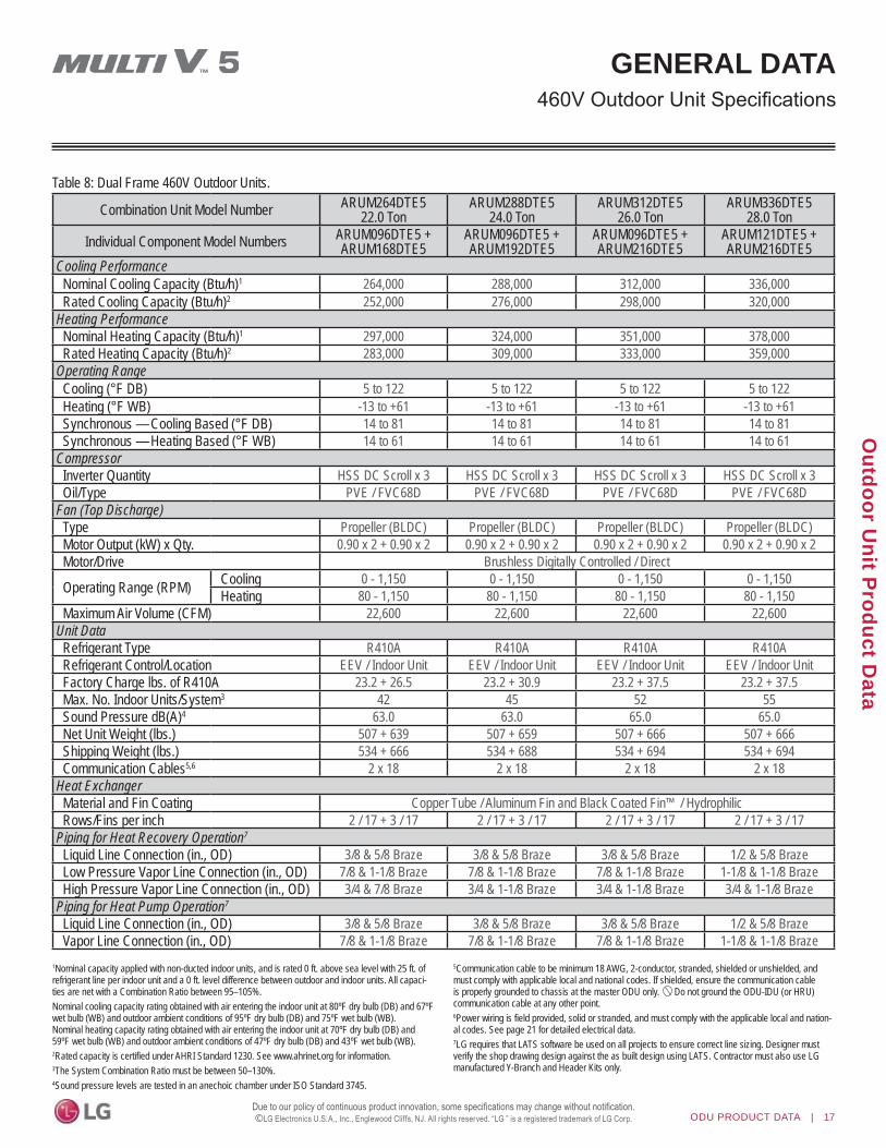
Combination Unit Model Number ARUM264DTE522.0 Ton
ARUM288DTE524.0 Ton
ARUM312DTE526.0 Ton
ARUM336DTE528.0 Ton
Individual Component Model Numbers ARUM096DTE5 + ARUM168DTE5
ARUM096DTE5 + ARUM192DTE5
ARUM096DTE5 + ARUM216DTE5
ARUM121DTE5 + ARUM216DTE5
Cooling PerformanceNominal Cooling Capacity (Btu/h)1 264,000 288,000 312,000 336,000Rated Cooling Capacity (Btu/h)2 252,000 276,000 298,000 320,000
Heating PerformanceNominal Heating Capacity (Btu/h)1 297,000 324,000 351,000 378,000Rated Heating Capacity (Btu/h)2 283,000 309,000 333,000 359,000
Operating RangeCooling (°F DB) 5 to 122 5 to 122 5 to 122 5 to 122Heating (°F WB) -13 to +61 -13 to +61 -13 to +61 -13 to +61Synchronous — Cooling Based (°F DB) 14 to 81 14 to 81 14 to 81 14 to 81Synchronous — Heating Based (°F WB) 14 to 61 14 to 61 14 to 61 14 to 61
CompressorInverter Quantity HSS DC Scroll x 3 HSS DC Scroll x 3 HSS DC Scroll x 3 HSS DC Scroll x 3Oil/Type PVE / FVC68D PVE / FVC68D PVE / FVC68D PVE / FVC68D
Fan (Top Discharge)Type Propeller (BLDC) Propeller (BLDC) Propeller (BLDC) Propeller (BLDC)Motor Output (kW) x Qty. 0.90 x 2 + 0.90 x 2 0.90 x 2 + 0.90 x 2 0.90 x 2 + 0.90 x 2 0.90 x 2 + 0.90 x 2Motor/Drive Brushless Digitally Controlled / Direct
Operating Range (RPM) Cooling 0 - 1,150 0 - 1,150 0 - 1,150 0 - 1,150Heating 80 - 1,150 80 - 1,150 80 - 1,150 80 - 1,150
Maximum Air Volume (CFM) 22,600 22,600 22,600 22,600Unit DataRefrigerant Type R410A R410A R410A R410ARefrigerant Control/Location EEV / Indoor Unit EEV / Indoor Unit EEV / Indoor Unit EEV / Indoor UnitFactory Charge lbs. of R410A 23.2 + 26.5 23.2 + 30.9 23.2 + 37.5 23.2 + 37.5Max. No. Indoor Units/System3 42 45 52 55Sound Pressure dB(A)4 63.0 63.0 65.0 65.0Net Unit Weight (lbs.) 507 + 639 507 + 659 507 + 666 507 + 666Shipping Weight (lbs.) 534 + 666 534 + 688 534 + 694 534 + 694Communication Cables5,6 2 x 18 2 x 18 2 x 18 2 x 18
Heat ExchangerMaterial and Fin Coating Copper Tube / Aluminum Fin and Black Coated Fin™ / HydrophilicRows/Fins per inch 2 / 17 + 3 / 17 2 / 17 + 3 / 17 2 / 17 + 3 / 17 2 / 17 + 3 / 17
Piping for Heat Recovery Operation7
Liquid Line Connection (in., OD) 3/8 & 5/8 Braze 3/8 & 5/8 Braze 3/8 & 5/8 Braze 1/2 & 5/8 BrazeLow Pressure Vapor Line Connection (in., OD) 7/8 & 1-1/8 Braze 7/8 & 1-1/8 Braze 7/8 & 1-1/8 Braze 1-1/8 & 1-1/8 BrazeHigh Pressure Vapor Line Connection (in., OD) 3/4 & 7/8 Braze 3/4 & 1-1/8 Braze 3/4 & 1-1/8 Braze 3/4 & 1-1/8 Braze
Piping for Heat Pump Operation7
Liquid Line Connection (in., OD) 3/8 & 5/8 Braze 3/8 & 5/8 Braze 3/8 & 5/8 Braze 1/2 & 5/8 BrazeVapor Line Connection (in., OD) 7/8 & 1-1/8 Braze 7/8 & 1-1/8 Braze 7/8 & 1-1/8 Braze 1-1/8 & 1-1/8 Braze
Table 8: Dual Frame 460V Outdoor Units.
1Nominal capacity applied with non-ducted indoor units, and is rated 0 ft. above sea level with 25 ft. of refrigerant line per indoor unit and a 0 ft. level difference between outdoor and indoor units. All capaci-ties are net with a Combination Ratio between 95–105%. Nominal cooling capacity rating obtained with air entering the indoor unit at 80ºF dry bulb (DB) and 67ºF wet bulb (WB) and outdoor ambient conditions of 95ºF dry bulb (DB) and 75ºF wet bulb (WB). Nominal heating capacity rating obtained with air entering the indoor unit at 70ºF dry bulb (DB) and 59ºF wet bulb (WB) and outdoor ambient conditions of 47ºF dry bulb (DB) and 43ºF wet bulb (WB).2Rated capacity is certified under AHRI Standard 1230. See www.ahrinet.org for information.3The System Combination Ratio must be between 50–130%.4Sound pressure levels are tested in an anechoic chamber under ISO Standard 3745.
5Communication cable to be minimum 18 AWG, 2-conductor, stranded, shielded or unshielded, and must comply with applicable local and national codes. If shielded, ensure the communication cable is properly grounded to chassis at the master ODU only. Do not ground the ODU-IDU (or HRU) communication cable at any other point.6Power wiring is field provided, solid or stranded, and must comply with the applicable local and nation-al codes. See page 21 for detailed electrical data.7LG requires that LATS software be used on all projects to ensure correct line sizing. Designer must verify the shop drawing design against the as built design using LATS. Contractor must also use LG manufactured Y-Branch and Header Kits only.

18 | ODU PRODUCT DATA
MU
LTI V
5 O
utdo
or U
nit E
ngin
eerin
g M
anua
l
©
Combination Unit Model Number ARUM360DTE530.0 Ton
ARUM384DTE532.0 Ton
ARUM408DTE534.0 Ton
Individual Component Model Numbers ARUM144DTE5 +ARUM216DTE5
ARUM168DTE5 + ARUM216DTE5
ARUM192DTE5 + ARUM216DTE5
Cooling PerformanceNominal Cooling Capacity (Btu/h)1 360,000 384,000 408,000Rated Cooling Capacity (Btu/h)2 344,000 366,000 390,000
Heating PerformanceNominal Heating Capacity (Btu/h)1 405,000 432,000 459,000Rated Heating Capacity (Btu/h)2 384,000 410,000 436,000
Operating RangeCooling (°F DB) 5 to 122 5 to 122 5 to 122Heating (°F WB) -13 to +61 -13 to +61 -13 to +61Synchronous — Cooling Based (°F DB) 14 to 81 14 to 81 14 to 81Synchronous — Heating Based (°F WB) 14 to 61 14 to 61 14 to 61
CompressorInverter Quantity HSS DC Scroll x 4 HSS DC Scroll x 4 HSS DC Scroll x 4Oil/Type PVE / FVC68D PVE / FVC68D PVE / FVC68D
Fan (Top Discharge)Type Propeller (BLDC) Propeller (BLDC) Propeller (BLDC)Motor Output (kW) x Qty. 0.90 x 2 + 0.90 x 2 0.90 x 2 + 0.90 x 2 0.90 x 2 + 0.90 x 2Motor/Drive Brushless Digitally Controlled / Direct
Operating Range (RPM) Cooling 0 - 1,150 0 - 1,150 0 - 1,150Heating 80 - 1,150 80 - 1,150 80 - 1,150
Maximum Air Volume (CFM) 22,600 22,600 22,600Unit DataRefrigerant Type R410A R410A R410ARefrigerant Control/Location EEV / Indoor Unit EEV / Indoor Unit EEV / Indoor UnitFactory Charge lbs. of R410A 26.5 + 37.5 26.5 + 37.5 30.9 + 37.5Max. No. Indoor Units/System3 58 61 64Sound Pressure dB(A)4 66.0 66.0 66.0Net Unit Weight (lbs.) 639 + 666 639 + 666 659 + 666Shipping Weight (lbs.) 666 + 694 666 + 694 688 + 694Communication Cables5,6 2 x 18 2 x 18 2 x 18
Heat ExchangerMaterial and Fin Coating Copper Tube / Aluminum Fin and Black Coated Fin™ / HydrophilicRows/Fins per inch 3 / 17 x 2 3 / 17 x 2 3 / 17 x 2
Piping for Heat Recovery Operation7
Liquid Line Connection (in., OD) 1/2 & 5/8 Braze 5/8 & 5/8 Braze 5/8 & 5/8 BrazeLow Pressure Vapor Line Connection (in., OD) 1-1/8 & 1-1/8 Braze 1-1/8 & 1-1/8 Braze 1-1/8 & 1-1/8 BrazeHigh Pressure Vapor Line Connection (in., OD) 7/8 & 1-1/8 Braze 7/8 & 1-1/8 Braze 1-1/8 & 1-1/8 Braze
Piping for Heat Pump Operation7
Liquid Line Connection (in., OD) 1/2 & 5/8 Braze 5/8 & 5/8 Braze 5/8 & 5/8 BrazeVapor Line Connection (in., OD) 1-1/8 & 1-1/8 Braze 1-1/8 & 1-1/8 Braze 1-1/8 & 1-1/8 Braze
Table 9: Dual Frame 460V Outdoor Units, continued.
GENERAL DATA
1Nominal capacity applied with non-ducted indoor units, and is rated 0 ft. above sea level with 25 ft. of refrigerant line per indoor unit and a 0 ft. level difference between outdoor and indoor units. All capaci-ties are net with a Combination Ratio between 95–105%. Nominal cooling capacity rating obtained with air entering the indoor unit at 80ºF dry bulb (DB) and 67ºF wet bulb (WB) and outdoor ambient conditions of 95ºF dry bulb (DB) and 75ºF wet bulb (WB). Nominal heating capacity rating obtained with air entering the indoor unit at 70ºF dry bulb (DB) and 59ºF wet bulb (WB) and outdoor ambient conditions of 47ºF dry bulb (DB) and 43ºF wet bulb (WB).2Rated capacity is certified under AHRI Standard 1230. See www.ahrinet.org for information.3The System Combination Ratio must be between 50–130%.4Sound pressure levels are tested in an anechoic chamber under ISO Standard 3745.
5Communication cable to be minimum 18 AWG, 2-conductor, stranded, shielded or unshielded, and must comply with applicable local and national codes. If shielded, ensure the communication cable is properly grounded to chassis at the master ODU only. Do not ground the ODU-IDU (or HRU) communication cable at any other point.6Power wiring is field provided, solid or stranded, and must comply with the applicable local and nation-al codes. See page 21 for detailed electrical data.7LG requires that LATS software be used on all projects to ensure correct line sizing. Designer must verify the shop drawing design against the as built design using LATS. Contractor must also use LG manufactured Y-Branch and Header Kits only.

ODU PRODUCT DATA | 19
Outdoor U
nit Product D
ata
©
Combination Unit Model Number ARUM432DTE536.0 Ton
ARUM456DTE538.0 Ton
ARUM480DTE540.0 Ton
ARUM504DTE542.0 Ton
Individual Component Model NumbersARUM121DTE5 + ARUM121DTE5 + ARUM192DTE5
ARUM121DTE5 +ARUM121DTE5 + ARUM216DTE5
ARUM121DTE5 +ARUM144DTE5 +ARUM216DTE5
ARUM121DTE5 +ARUM168DTE5 +ARUM216DTE5
Cooling PerformanceNominal Cooling Capacity (Btu/h)1 432,000 456,000 480,000 504,000Rated Cooling Capacity (Btu/h)2 412,000 434,000 458,000 480,000
Heating PerformanceNominal Heating Capacity (Btu/h)1 486,000 513,000 540,000 567,000Rated Heating Capacity (Btu/h)2 460,000 488,000 513,000 539,000
Operating RangeCooling (°F DB) 5 to 122 5 to 122 5 to 122 5 to 122Heating (°F WB) -13 to +61 -13 to +61 -13 to +61 -13 to +61Synchronous — Cooling Based (°F DB) 14 to 81 14 to 81 14 to 81 14 to 81Synchronous — Heating Based (°F WB) 14 to 61 14 to 61 14 to 61 14 to 61
CompressorInverter Quantity HSS DC Scroll x 4 HSS DC Scroll x 4 HSS DC Scroll x 5 HSS DC Scroll x 5Oil/Type PVE / FVC68D PVE / FVC68D PVE / FVC68D PVE / FVC68D
Fan (Top Discharge)Type Propeller (BLDC) Propeller (BLDC) Propeller (BLDC) Propeller (BLDC)Motor Output (kW) x Qty. 0.90x2 + 0.90x2 + 0.90x2 0.90x2 + 0.90x2 + 0.90x2 0.90x2 + 0.90x2 + 0.90x2 0.90x2 + 0.90x2 + 0.90x2Motor/Drive Brushless Digitally Controlled / Direct
Operating Range (RPM) Cooling 0 - 1,150 0 - 1,150 0 - 1,150 0 - 1,150Heating 80 - 1,150 80 - 1,150 80 - 1,150 80 - 1,150
Maximum Air Volume (CFM) 33,900 33,900 33,900 33,900Unit DataRefrigerant Type R410A R410A R410A R410ARefrigerant Control/Location EEV / Indoor Unit EEV / Indoor Unit EEV / Indoor Unit EEV / Indoor UnitFactory Charge lbs. of R410A 23.2 + 23.2 + 30.9 23.2 + 23.2 + 37.5 23.2 + 26.5 + 37.5 23.2 + 26.5 + 37.5Max. No. Indoor Units/System3 64 64 64 64Sound Pressure dB(A)4 66.0 66.0 67.0 67.0Net Unit Weight (lbs.) 507 + 507 + 659 507 + 507 + 666 507 + 639 + 666 507 + 639 + 666Shipping Weight (lbs.) 534 + 534 + 688 534 + 534 + 694 534 + 666 + 694 534 + 666 + 694Communication Cables5,6 2 x 18 2 x 18 2 x 18 2 x 18
Heat ExchangerMaterial and Fin Coating Copper Tube / Aluminum Fin and Black Coated Fin™ / HydrophilicRows/Fins per inch 2/17 x 2 + 3/17 2 / 17 x 2 + 3 / 17 2 / 17 + 3 / 17 x 2 2 / 17 + 3 / 17 x 2
Piping for Heat Recovery Operation7
Liquid Line Connection (in., OD) 1/2 & 1/2 & 5/8 Braze 1/2 & 1/2 & 5/8 Braze 1/2 & 1/2 & 5/8 Braze 1/2 & 5/8 & 5/8 BrazeLow Pressure Vapor Line Conn. (in., OD) 1-1/8 & 1-1/8 & 1-1/8 Braze 1-1/8 & 1-1/8 & 1-1/8 Braze 1-1/8 & 1-1/8 & 1-1/8 Braze 1-1/8 & 1-1/8 & 1-1/8 BrazeHigh Pressure Vapor Line Conn. (in., OD) 3/4 & 3/4 & 1-1/8 Braze 3/4 & 3/4 & 1-1/8 Braze 3/4 & 7/8 & 1-1/8 Braze 3/4 & 7/8 & 1-1/8 Braze
Piping for Heat Pump Operation7
Liquid Line Connection (in., OD) 1/2 & 1/2 & 5/8 Braze 1/2 & 1/2 & 5/8 Braze 1/2 & 1/2 & 5/8 Braze 1/2 & 5/8 & 5/8 BrazeVapor Line Connection (in., OD) 1-1/8 & 1-1/8 & 1-1/8 Braze 1-1/8 & 1-1/8 & 1-1/8 Braze 1-1/8 & 1-1/8 & 1-1/8 Braze 1-1/8 & 1-1/8 & 1-1/8 Braze
Table 10: Triple Frame 460V Outdoor Units.
GENERAL DATA
1Nominal capacity applied with non-ducted indoor units, and is rated 0 ft. above sea level with 25 ft. of refrigerant line per indoor unit and a 0 ft. level difference between outdoor and indoor units. All capaci-ties are net with a Combination Ratio between 95–105%. Nominal cooling capacity rating obtained with air entering the indoor unit at 80ºF dry bulb (DB) and 67ºF wet bulb (WB) and outdoor ambient conditions of 95ºF dry bulb (DB) and 75ºF wet bulb (WB). Nominal heating capacity rating obtained with air entering the indoor unit at 70ºF dry bulb (DB) and 59ºF wet bulb (WB) and outdoor ambient conditions of 47ºF dry bulb (DB) and 43ºF wet bulb (WB).2Rated capacity is certified under AHRI Standard 1230. See www.ahrinet.org for information.3The System Combination Ratio must be between 50–130%.4Sound pressure levels are tested in an anechoic chamber under ISO Standard 3745.
5Communication cable to be minimum 18 AWG, 2-conductor, stranded, shielded or unshielded, and must comply with applicable local and national codes. If shielded, ensure the communication cable is properly grounded to chassis at the master ODU only. Do not ground the ODU-IDU (or HRU) communication cable at any other point.6Power wiring is field provided, solid or stranded, and must comply with the applicable local and nation-al codes. See page 21 for detailed electrical data.7LG requires that LATS software be used on all projects to ensure correct line sizing. Designer must verify the shop drawing design against the as built design using LATS. Contractor must also use LG manufactured Y-Branch and Header Kits only.

20 | ODU PRODUCT DATA
MU
LTI V
5 O
utdo
or U
nit E
ngin
eerin
g M
anua
l
©
ELECTRICAL DATA208-230V Outdoor Unit Electrical Data
Nom. Tons
Unit Model Nos.
Compressor (Comp.) Condenser Fan Motor(s) MCA MOCP RFA
Comp. Qty.
Motor Amps
Fan Qty.
Amps
Motor RLA (Ea.)FLA (Ea.)
Frame Frame Frame
1 2 3 1 2 3 1 2 3Frame
1 2 3 Frame1 2 3Comp.
AComp.
BComp.
AComp.
BComp.
AComp.
B6.0 ARUM072BTE5 1 14.1 - - - - - 1 5.0 - - 22.6 - - 35 - - 35 - -8.0 ARUM096BTE5 1 16.4 - - - - - 2 8.0 - - 28.5 - - 40 - - 40 - -
10.0 ARUM121BTE5 1 18.3 - - - - - 2 8.0 - - 30.9 - - 40 - - 40 - -12.0 ARUM144BTE5 2 19.8 18.3 - - - - 2 8.0 - - 51.1 - - 70 - - 70 - -14.0 ARUM168BTE5 2 21.2 19.1 - - - - 2 8.0 - - 53.6 - - 70 - - 70 - -16.0 ARUM192BTE5 2 23.3 20.8 - - - - 2 8.0 - - 57.9 - - 80 - - 80 - -18.0 ARUM216BTE5 2 24.3 21.9 - - - - 2 8.0 - - 60.3 - - 80 - - 80 - -20.0 ARUM241BTE5 2 25.6 23.2 - - - - 2 8.0 - - 63.2 - - 80 - - 80 - -22.0 ARUM264BTE5 3 21.2 19.1 16.4 - - - 4 8.0 8.0 - 53.6 28.5 - 70 40 - 70 40 -24.0 ARUM288BTE5 3 23.3 20.8 16.4 - - - 4 8.0 8.0 - 57.9 28.5 - 80 40 - 80 40 -26.0 ARUM312BTE5 3 24.3 21.9 16.4 - - - 4 8.0 8.0 - 60.3 28.5 - 80 40 - 80 40 -28.0 ARUM336BTE5 3 24.3 21.9 18.3 - - - 4 8.0 8.0 - 60.3 30.9 - 80 40 - 80 40 -30.0 ARUM360BTE5 4 24.3 21.9 19.8 18.3 - - 4 8.0 8.0 - 60.3 51.1 - 80 70 - 80 70 -32.0 ARUM384BTE5 4 24.3 21.9 21.2 19.1 - - 4 8.0 8.0 - 60.3 53.6 - 80 70 - 80 70 -34.0 ARUM408BTE5 4 24.3 21.9 23.3 20.8 - - 4 8.0 8.0 - 60.3 57.9 - 80 80 - 80 80 -36.0 ARUM432BTE5 4 23.3 20.8 18.3 - 18.3 - 6 8.0 8.0 8.0 57.9 30.9 30.9 80 40 40 80 40 4038.0 ARUM456BTE5 4 24.3 21.9 18.3 - 18.3 - 6 8.0 8.0 8.0 60.3 30.9 30.9 80 40 40 80 40 4040.0 ARUM480BTE5 5 24.3 21.9 19.8 18.3 18.3 - 6 8.0 8.0 8.0 60.3 51.1 30.9 80 70 40 80 70 4042.0 ARUM504BTE5 5 24.3 21.9 21.2 19.1 18.3 - 6 8.0 8.0 8.0 60.3 53.6 30.9 80 70 40 80 70 40
For component model nos. see the specification tables on p. 10-14.Voltage tolerance is 187V to 253V.Maximum allowable voltage unbalance is 2%.MCA = Minimum Circuit Ampacity.
Maximum Overcurrent Protection (MOCP) is calculated as follows: (Largest motor FLA x 2.25) + (Sum of other motor FLA) rounded down to the nearest standard fuse size. RFA = Recommended Fuse Amps.*SCCR rating: 5kA RMS Symmetrical.
Table 11: 208-230V, 60Hz, 3-Phase Outdoor Units.

ODU PRODUCT DATA | 21
Outdoor U
nit Product D
ata
©
ELECTRICAL DATA460V Outdoor Unit Electrical Data
Table 12: 460V, 60Hz, 3-Phase Outdoor Units.
Nom. Tons
Unit Model Nos.
Compressor (Comp.) Condenser Fan Motor(s) MCA MOCP RFA
Comp. Qty.
Motor Amps
Fan Qty.
Amps
Motor RLA (Ea.)FLA (Ea.)
Frame Frame Frame
1 2 3 1 2 3 1 2 3Frame
1 2 3 Frame1 2 3Comp.
AComp.
BComp.
AComp.
BComp.
AComp.
B6.0 ARUM072DTE5 1 7.8 - - - - - 1 3.0 - - 12.8 - - 20 - - 20 - -8.0 ARUM096DTE5 1 9.1 - - - - - 2 5.0 - - 16.4 - - 25 - - 25 - -
10.0 ARUM121DTE5 1 10.7 - - - - - 2 5.0 - - 18.4 - - 25 - - 25 - -12.0 ARUM144DTE5 2 10.3 8.5 - - - - 2 5.0 - - 26.4 - - 35 - - 35 - -14.0 ARUM168DTE5 2 11.4 9.2 - - - - 2 5.0 - - 28.5 - - 35 - - 35 - -16.0 ARUM192DTE5 2 14.8 12.2 - - - - 2 5.0 - - 35.7 - - 50 - - 50 - -18.0 ARUM216DTE5 2 15.5 13.9 - - - - 2 5.0 - - 38.3 - - 50 - - 50 - -20.0 ARUM241DTE5 2 16.9 15.3 - - - - 2 5.0 - - 41.4 - - 50 - - 50 - -22.0 ARUM264DTE5 3 11.4 9.2 9.1 - - - 4 5.0 5.0 - 28.5 16.4 - 35 25 - 35 25 -24.0 ARUM288DTE5 3 14.8 12.2 9.1 - - - 4 5.0 5.0 - 35.7 16.4 - 50 25 - 50 25 -26.0 ARUM312DTE5 3 15.5 13.9 9.1 - - - 4 5.0 5.0 - 38.3 16.4 - 50 25 - 50 25 -28.0 ARUM336DTE5 3 15.5 13.9 10.7 - - - 4 5.0 5.0 - 38.3 18.4 - 50 25 - 50 25 -30.0 ARUM360DTE5 4 15.5 13.9 10.3 8.5 - - 4 5.0 5.0 - 38.3 26.4 - 50 35 - 50 35 -32.0 ARUM384DTE5 4 15.5 13.9 11.4 9.2 - - 4 5.0 5.0 - 38.3 28.5 - 50 35 - 50 35 -34.0 ARUM408DTE5 4 15.5 13.9 14.8 12.2 - - 4 5.0 5.0 - 38.3 35.7 - 50 50 - 50 50 -36.0 ARUM432DTE5 4 14.8 12.2 10.7 - 10.7 - 6 5.0 5.0 5.0 35.7 18.4 18.4 50 25 25 50 25 2538.0 ARUM456DTE5 4 15.5 13.9 10.7 - 10.7 - 6 5.0 5.0 5.0 38.3 18.4 18.4 50 25 25 50 25 25 40.0 ARUM480DTE5 5 15.5 13.9 10.3 8.5 10.7 - 6 5.0 5.0 5.0 38.3 26.4 18.4 50 35 25 50 35 25 42.0 ARUM504DTE5 5 15.5 13.9 11.4 9.2 10.7 - 6 5.0 5.0 5.0 38.3 28.5 18.4 50 35 25 50 35 25
For component model nos. see the specification tables on p. 15-19.Voltage tolerance is 414V to 528V.Maximum allowable voltage unbalance is 2%.MCA = Minimum Circuit Ampacity.
Maximum Overcurrent Protection (MOCP) is calculated as follows: (Largest motor FLA x 2.25) + (Sum of other motor FLA) rounded down to the nearest standard fuse size. RFA = Recommended Fuse Amps.*SCCR rating: 5kA RMS Symmetrical.

22 | ODU PRODUCT DATA
MU
LTI V
5 O
utdo
or U
nit E
ngin
eerin
g M
anua
l
©
Outdoor Unit Model No.Nominal Cooling
(Btu/h)
Indoor UnitsSum of Indoor Unit Nominal Cooling Capacities (Btu/h)
208-230V 460V Max. Qty. Min. Capacity (Btu/h) (50%)*
Max. Capacity (Btu/h) (130%)
ARUM072BTE5 ARUM072DTE5 72,000 13 36,000 93,600ARUM096BTE5 ARUM096DTE5 96,000 16 48,000 124,800ARUM121BTE5 ARUM121DTE5 120,000 20 60,000 156,000ARUM144BTE5 ARUM144DTE5 144,000 24 72,000 187,200ARUM168BTE5 ARUM168DTE5 168,000 29 84,000 218,400ARUM192BTE5 ARUM192DTE5 192,000 32 96,000 249,600ARUM216BTE5 ARUM216DTE5 216,000 35 108,000 280,800ARUM241BTE5 ARUM241DTE5 240,000 39 120,000 312,000ARUM264BTE5 ARUM264DTE5 264,000 42 132,000 343,200ARUM288BTE5 ARUM288DTE5 288,000 45 144,000 374,400ARUM312BTE5 ARUM312DTE5 312,000 52 156,000 405,600ARUM336BTE5 ARUM336DTE5 336,000 55 168,000 436,800ARUM360BTE5 ARUM360DTE5 360,000 58 180,000 468,000ARUM384BTE5 ARUM384DTE5 384,000 61 192,000 499,200ARUM408BTE5 ARUM408DTE5 408,000 64 204,000 530,400ARUM432BTE5 ARUM432DTE5 432,000 64 216,000 561,600ARUM456BTE5 ARUM456DTE5 456,000 64 228,000 592,800ARUM480BTE5 ARUM480DTE5 480,000 64 240,000 624,000ARUM504BTE5 ARUM504DTE5 504,000 64 252,000 655,200
Table 13: Outdoor Unit Connection Limitations.
CONNECTION LIMITATIONS

ODU PRODUCT DATA | 23
Outdoor U
nit Product D
ata
©
DIMENSIONSARUM072BTE5 / DTE5
7/8” Diameter Leak Test Hole
L9
L10
L9 6 – 1/2
5 – 9/16L10
L11
L12
L13
L14L15
L11
L12
8 – 5/8
6 – 7/16
L13 24 – 5/8
L14
L15
26 – 7/16
29 – 3/16
Two (2) 7/8” Diameter Wire Routing Holes (Bottom)
Piping Routing Holes (Bottom); two - ø2-5/8”, ø2-1/8”
Power Cord Routing Hole (Bottom); two (2) - ø2”
M5M6M7M8M9
M10M11
M12
M13
M14
M15
M5
M8M7M6
M9M10M11M12M13M14M15
13 – 1/8”12 – 5/16”11 – 3/4”
9 – 11/16”9 – 5/16”7 – 5/16”6 – 3/16”6 – 13/16”4 – 1/2”
3 – 11/16”3”
Right Side ViewLeft Side View

24 | ODU PRODUCT DATA
MU
LTI V
5 O
utdo
or U
nit E
ngin
eerin
g M
anua
l
©
DIMENSIONSARUM096BTE5 / DTE5, 121BTE5 / DTE5, 144BTE5 / DTE5,168BTE5 / DTE5, 192BTE5 / DTE5, 216BTE5 / DTE5, 241BTE5 / DTE5
M5
M8M7M6
M9M10M11M12M13M14M15
11 – 15/16”11 – 1/16”10 – 1/2”8 – 7/16”8 – 1/8”6 – 1/16”
4 – 15/16”7 – 1/2”
4 – 13/16”4 – 5/16”
3”
L9
L107/8” Diameter Leak Test Hole
Left Side ViewL9
L10
L11
L12
L13L14
6 – 1/2”
5 – 9/16”
L11
L12
8 – 5/8
6 – 7/16
9 – 15/16”
L13
L14
3 – 5/8”
Right Side View
Two (2) 7/8” Diameter Wire Routing Holes (Bottom)
M5M6M7
M8M9
M10M11
M12
M13
M15
M14
M16
Power Cord Routing Hole (Bottom); two (2) - ø2”
Holes (Bottom); two - ø2-5/8,” ø2-1/8”
M163 – 5/8”
PipingRouting
Multi-FrameConfigurationsPlease refer to multi-frameplacement information andpiping rules in theMulti V 5 EngineeringManual and the Multi V 5Installation Manual.

ODU PRODUCT DATA | 25
Outdoor U
nit Product D
ata
©
WIRING DIAGRAMS
ARUM072BTE5208-230V Outdoor Units
10/6

26 | ODU PRODUCT DATA
MU
LTI V
5 O
utdo
or U
nit E
ngin
eerin
g M
anua
l
©
WIRING DIAGRAMS208-230V Outdoor UnitsARUM096BTE5 / ARUM121BTE5
10/6

ODU PRODUCT DATA | 27
Outdoor U
nit Product D
ata
©
WIRING DIAGRAMS208-230V Outdoor Units
ARUM144BTE5 / ARUM168BTE5
12/6

28 | ODU PRODUCT DATA
MU
LTI V
5 O
utdo
or U
nit E
ngin
eerin
g M
anua
l
©
ARUM192BTE5 / ARUM216BTE5 / ARUM241BTE5
WIRING DIAGRAMS208-230V Outdoor Units
12/1

ODU PRODUCT DATA | 29
Outdoor U
nit Product D
ata
©
WIRING DIAGRAMS
ARUM072DTE5460V Outdoor Units
10/6

30 | ODU PRODUCT DATA
MU
LTI V
5 O
utdo
or U
nit E
ngin
eerin
g M
anua
l
©
WIRING DIAGRAMS
ARUM096DTE5 / ARUM121DTE5460V Outdoor Units
10/6

ODU PRODUCT DATA | 31
Outdoor U
nit Product D
ata
©
ARUM144DTE5 / ARUM168DTE5
WIRING DIAGRAMS460V Outdoor Units
12/1

32 | ODU PRODUCT DATA
MU
LTI V
5 O
utdo
or U
nit E
ngin
eerin
g M
anua
l
©
ARUM192DTE5 / ARUM216DTE5 / ARUM241DTE5
WIRING DIAGRAMS460V Outdoor Units
12/1

ODU PRODUCT DATA | 33
Outdoor U
nit Product D
ata
©
REFRIGERANT FLOW DIAGRAMSARUM072BTE5 / DTE5, ARUM096BTE5 / DTE5, ARUM121BTE5 / DTE5
Heat Pump Operation — Cooling Mode
Heat Pump – Cooling Mode
M M
s
s
s
s
s
s
s
SCEEV
EEV
Indoor Unit Indoor Unit
Indoor HEX EEVIndoor HEX
Fan Fan
MM
Fan
*6 ton unitonly has 1 fan
MotorOutdoorTemperature
Sensor
Outdoor Unit HEXTemperature Sensor
Outdoor Unit HEXTemperature Sensor
OutdoorUnit HEX
TemperatureSensor
V
4-Way Valve 2
High PressureSensor
4-Way Valve 1
SuctionTemperatureSensor
ReceiverReceiverOutlet
LowPressure Sensor
CompDischarge
Temperatue Sensor
Oil Separator
Liquid PipeTemperature Sensor
Low Pressure Vapor Pipe
High Pressure Vapor Pipe
Liquid Pipe
InverterComp
Sub-Cooling CircuitOutlet Temperature Sensor
Sub-Cooling HEX
Sub-Cooling Circuit InletTemperature Sensor
Accum
Pressure Switch
Upper OutdoorEEV Close
Lower OutdoorEEV Receiver
InletSCSuction
Oil Return
Heatsink
Active PathValve
Comp Vapor Injection
Pressure Sensor
Pressure Switch
Temperature SensorRemarks
SVC Valve
Check Valve
EEV
Solenoid Valve
Strainer
High Temperature High Pressure VaporHigh Temperature High Pressure LiquidHigh Temperature High Pressure Liquid (Conditional)Low Temperature Low Pressure Vapor
Lower Hotapor Valve
Upper HotVapor ValveClose
Close

34 | ODU PRODUCT DATA
MU
LTI V
5 O
utdo
or U
nit E
ngin
eerin
g M
anua
l
©
REFRIGERANT FLOW DIAGRAMSARUM072BTE5 / DTE5, ARUM096BTE5 / DTE5, ARUM121BTE5 / DTE5 Heat Pump Operation — Heating Mode
Heat Pump – Heating Mode
M M
s
s
s
s
s
s
s
SCEEV
EEV
Indoor Unit Indoor Unit
Indoor HEX EEVIndoor HEX
Fan Fan
MOutdoor
TemperatureSensor
Outdoor Unit HEXTemperature Sensor
Outdoor Unit HEXTemperature Sensor
OutdoorUnit HEX
TemperatureSensor
Lower HotVapor Valve
4-Way Valve 2
High PressureSensor
4-Way Valve 1
SuctionTemperatureSensor
ReceiverReceiverOutlet
LowPressure Sensor
CompDischarge
Temperatue Sensor
Oil Separator
Liquid PipeTemperature Sensor
Low Pressure Vapor PipeHigh Pressure Vapor Pipe
Liquid Pipe
InverterComp
Sub-Cooling CircuitOutlet Temperature Sensor
Sub-Cooling HEX
Sub-Cooling Circuit InletTemperature Sensor
Accum
Pressure Switch
Upper HotVapor Valve
Upper Outdoor EEV
Low OutdoorEEV Receiver
InletSCSuction
Oil Return
Heatsink
Active PathValve
Comp Vapor Injection
Pressure Sensor
Pressure Switch
Temperature SensorRemarks
SVC Valve
Check Valve
EEV
Solenoid Valve
Strainer
M
Fan
*6 ton unitonly has 1 fan
Motor
High Temperature High Pressure VaporHigh Temperature High Pressure LiquidHigh Temperature High Pressure Liquid (Conditional)Low Temperature Low Pressure Vapor

ODU PRODUCT DATA | 35
Outdoor U
nit Product D
ata
©
REFRIGERANT FLOW DIAGRAMSARUM072BTE5 / DTE5, ARUM096BTE5 / DTE5, ARUM121BTE5 / DTE5
Heat Pump Operation — Oil Return and Defrost
Heat Pump – Oil Return and Defrost Operation
s
s
s
s
s
s
s
Pressure Sensor
Pressure Switch
Temperature SensorRemarks
SVC Valve
Check Valve
EEV
Solenoid Valve
Strainer
M M
SCEEV
EEV
Indoor Unit Indoor Unit
Indoor HEX EEVIndoor HEX
MOutdoorTemperature
Sensor
Outdoor Unit HEXTemperature Sensor
Outdoor Unit HEXTemperature Sensor
OutdoorUnit HEX
TemperatureSensor
Lower HotVapor Valve
4-Way Valve 2
High PressureSensor
4-Way Valve 1
SuctionTemperatureSensor
ReceiverReceiverOutlet
LowPressure Sensor
CompDischarge
Temperatue Sensor
Oil Separator
Liquid PipeTemperature Sensor
Low Pressure Vapor PipeHigh Pressure Vapor Pipe
Liquid Pipe
InverterComp
Sub-Cooling CircuitOutlet Temperature Sensor
Sub-Cooling HEX
Sub-Cooling Circuit InletTemperature Sensor
Accum
Pressure Switch
Upper HotVapor ValveClose
Upper OutdoorEEV Close
Lower OutdoorEEV Receiver
InletSCSuction
Oil Return
Heatsink
Active PathValve
Comp Vapor Injection
M
Fan
*6 ton unitonly has 1 fan
Motor
High Temperature High Pressure VaporHigh Temperature High Pressure LiquidHigh Temperature High Pressure Liquid (Conditional)Low Temperature Low Pressure Vapor
Close

36 | ODU PRODUCT DATA
MU
LTI V
5 O
utdo
or U
nit E
ngin
eerin
g M
anua
l
©
REFRIGERANT FLOW DIAGRAMSARUM072BTE5 / DTE5, ARUM096BTE5 / DTE5, ARUM121BTE5 / DTE5 Heat Pump Operation — Lower Heat Exchanger Defrost
Heat Pump – Lower HEX Defrost Operation
s
s
s
s
s
s
s
M M
SCEEV
EEV
Indoor Unit Indoor Unit
Indoor HEX EEVIndoor HEX
Fan Fan
MOutdoor
TemperatureSensor
Outdoor Unit HEXTemperature Sensor
Outdoor Unit HEXTemperature Sensor
OutdoorUnit HEX
TemperatureSensor
Lower HotVapor Valve
4-Way Valve 2
High PressureSensor
4-Way Valve 1
SuctionTemperatureSensor
ReceiverReceiverOutlet
LowPressure Sensor
CompDischarge
Temperatue Sensor
Oil Separator
Liquid PipeTemperature Sensor
Low Pressure Vapor Pipe
High Pressure Vapor Pipe
Liquid Pipe
InverterComp
Sub-Cooling CircuitOutlet Temperature Sensor
Sub-Cooling HEX
Sub-Cooling Circuit InletTemperature Sensor
Accum
Pressure Switch
Upper HotVapor Valve
Upper Outdoor EEV
Low OutdoorEEV Receiver
InletSCSuction
Oil Return
Heatsink
Active PathValve
Comp Vapor Injection
Pressure Sensor
Pressure Switch
Temperature SensorRemarks
SVC Valve
Check Valve
EEV
Solenoid Valve
Strainer
M
Fan
*6 ton unitonly has 1 fan
Motor
High Temperature High Pressure VaporHigh Temperature High Pressure LiquidHigh Temperature High Pressure Liquid (Conditional)Low Temperature Low Pressure Vapor

ODU PRODUCT DATA | 37
Outdoor U
nit Product D
ata
©
REFRIGERANT FLOW DIAGRAMSARUM072BTE5 / DTE5, ARUM096BTE5 / DTE5, ARUM121BTE5 / DTE5
Heat Pump Operation — Upper Heat Exchanger Defrost
Heat Pump – Upper HEX Defrost Operation
s
s
s
s
s
s
s
M M
SCEEV
EEV
Indoor Unit Indoor Unit
Indoor HEX EEVIndoor HEX
Fan Fan
MOutdoor
TemperatureSensor
Outdoor Unit HEXTemperature Sensor
Outdoor Unit HEXTemperature Sensor
OutdoorUnit HEX
TemperatureSensor
Lower HotVapor Valve
4-Way Valve 2
High PressureSensor
4-Way Valve 1
SuctionTemperatureSensor
ReceiverReceiverOutlet
LowPressure Sensor
CompDischarge
Temperatue Sensor
Oil Separator
Liquid PipeTemperature Sensor
Low Pressure Vapor PipeHigh Pressure Vapor Pipe
Liquid Pipe
InverterComp
Sub-Cooling CircuitOutlet Temperature Sensor
Sub-Cooling HEX
Sub-Cooling Circuit InletTemperature Sensor
Accum
Pressure Switch
Upper HotVapor Valve
Upper Outdoor EEV
Low OutdoorEEV Receiver
InletSCSuction
Oil Return
Heatsink
Active PathValve
Comp Vapor Injection
Pressure Sensor
Pressure Switch
Temperature SensorRemarks
SVC Valve
Check Valve
EEV
Solenoid Valve
Strainer
M
Fan
*6 ton unitonly has 1 fan
Motor
High Temperature High Pressure VaporHigh Temperature High Pressure LiquidHigh Temperature High Pressure Liquid (Conditional)Low Temperature Low Pressure Vapor

38 | ODU PRODUCT DATA
MU
LTI V
5 O
utdo
or U
nit E
ngin
eerin
g M
anua
l
©
REFRIGERANT FLOW DIAGRAMSARUM144BTE5/DTE5, 168BTE5/DTE5, 192BTE5/DTE5, 216BTE5/DTE5, 241BTE5/DTE5Heat Pump Operation — Cooling Mode
Heat Pump – Cooling Mode
MM
s s
s
s
s
s
s
s
s
EEV
Indoor Unit
Indoor HEX
Fan
EEV
Indoor Unit
Indoor HEX
Fan
MM
Fan
MotorOutdoor
TemperatureSensor
Outdoor Unit HEXTemperature Sensor
Outdoor Unit HEXTemperature Sensor
OutdoorUnit HEX
TemperatureSensor
4-Way Valve 2
High PressureSensor
4-Way Valve 1
SuctionTemperatureSensor
ReceiverReceiverOutlet
LowPressure Sensor
Comp 1Discharge
Temperatue Sensor
Comp 2Discharge
Temperatue Sensor
Oil Separator Oil Separator
Liquid PipeTemperature Sensor
Low Pressure Vapor PipeHigh Pressure Vapor Pipe
Liquid Pipe
InverterComp 1
OilBalance
OilBalance
Sub-Cooling CircuitOutlet Temperature Sensor
Sub-Cooling HEX
Sub-Cooling Circuit InletTemperature Sensor
SCEEV
Accum
Pressure Switch
Lower OutdoorEEV Receiver
InletSCSuction
Oil Return
Heatsink
Active PathValve
Comp 1 Vapor Injection
InverterComp 2
Comp 2 Vapor Injection
Pressure Sensor
Pressure Switch
Temperature SensorRemarks
SVC Valve
Check Valve
EEV
Solenoid Valve
Strainer
High Temperature High Pressure VaporHigh Temperature High Pressure LiquidHigh Temperature High Pressure Liquid (Conditional)Low Temperature Low Pressure Vapor
Lower HotVapor Valve
Upper HotVapor ValveClose
Upper OutdoorEEV Close
Close
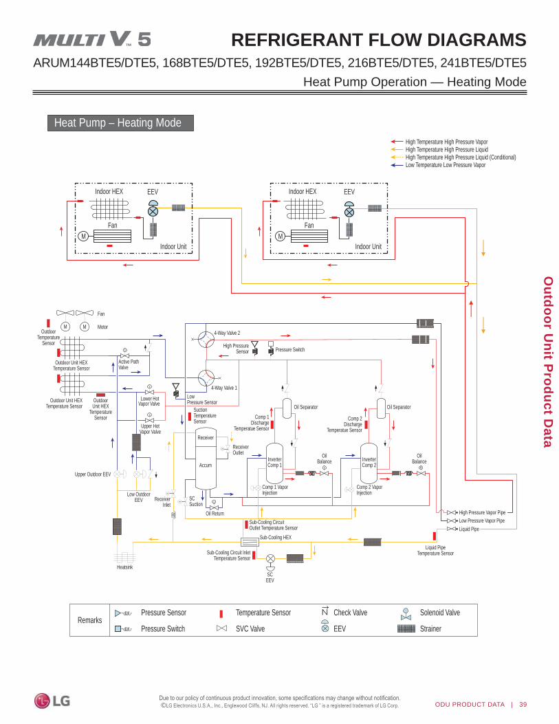
ODU PRODUCT DATA | 39
Outdoor U
nit Product D
ata
©
REFRIGERANT FLOW DIAGRAMSARUM144BTE5/DTE5, 168BTE5/DTE5, 192BTE5/DTE5, 216BTE5/DTE5, 241BTE5/DTE5
Heat Pump Operation — Heating Mode
Heat Pump – Heating Mode
s s
s
s
s
s
s
s
s
MM
s
EEV
Indoor Unit
Indoor HEX
Fan
EEV
Indoor Unit
Indoor HEX
Fan
MM
Fan
MotorOutdoor
TemperatureSensor
Outdoor Unit HEXTemperature Sensor
Outdoor Unit HEXTemperature Sensor
OutdoorUnit HEX
TemperatureSensor
Lower HotVapor Valve
4-Way Valve 2
High PressureSensor
4-Way Valve 1
SuctionTemperatureSensor
ReceiverReceiverOutlet
LowPressure Sensor
Comp 1Discharge
Temperatue Sensor
Comp 2Discharge
Temperatue Sensor
Oil Separator Oil Separator
Liquid PipeTemperature Sensor
Low Pressure Vapor PipeHigh Pressure Vapor Pipe
Liquid Pipe
InverterComp 1
OilBalance
OilBalance
Sub-Cooling CircuitOutlet Temperature Sensor
Sub-Cooling HEX
Sub-Cooling Circuit InletTemperature Sensor
SCEEV
Accum
Pressure Switch
Upper HotVapor Valve
Upper Outdoor EEV
Low OutdoorEEV Receiver
InletSCSuction
Oil Return
Heatsink
Active PathValve
Comp 1 Vapor Injection
InverterComp 2
Comp 2 Vapor Injection
Pressure Sensor
Pressure Switch
Temperature SensorRemarks
SVC Valve
Check Valve
EEV
Solenoid Valve
Strainer
High Temperature High Pressure VaporHigh Temperature High Pressure LiquidHigh Temperature High Pressure Liquid (Conditional)Low Temperature Low Pressure Vapor

40 | ODU PRODUCT DATA
MU
LTI V
5 O
utdo
or U
nit E
ngin
eerin
g M
anua
l
©
REFRIGERANT FLOW DIAGRAMSARUM144BTE5/DTE5, 168BTE5/DTE5, 192BTE5/DTE5, 216BTE5/DTE5, 241BTE5/DTE5Heat Pump Operation — Oil Return and Defrost
Heat Pump – Oil Return and Defrost Operation
s s
s
s
s
s
s
s
s
MM
EEV
Indoor Unit
Indoor HEX
Fan
EEV
Indoor Unit
Indoor HEX
Fan
MM
Fan
MotorOutdoor
TemperatureSensor
Outdoor Unit HEXTemperature Sensor
Outdoor Unit HEXTemperature Sensor
OutdoorUnit HEX
TemperatureSensor
4-Way Valve 2
High PressureSensor
4-Way Valve 1
SuctionTemperatureSensor
ReceiverReceiverOutlet
LowPressure Sensor
Comp 1Discharge
Temperatue Sensor
Comp 2Discharge
Temperatue Sensor
Oil Separator Oil Separator
Liquid PipeTemperature Sensor
Low Pressure Vapor Pipe
High Pressure Vapor Pipe
Liquid Pipe
InverterComp 1
OilBalance
OilBalance
Sub-Cooling CircuitOutlet Temperature Sensor
Sub-Cooling HEX
Sub-Cooling Circuit InletTemperature Sensor
SCEEV
Accum
Pressure Switch
Lower OutdoorEEV Receiver
InletSCSuction
Oil Return
Heatsink
Active PathValve
Comp 1 Vapor Injection
InverterComp 2
Comp 2 Vapor Injection
Pressure Sensor
Pressure Switch
Temperature SensorRemarks
SVC Valve
Check Valve
EEV
Solenoid Valve
Strainer
High Temperature High Pressure VaporHigh Temperature High Pressure LiquidHigh Temperature High Pressure Liquid (Conditional)Low Temperature Low Pressure Vapor
Lower HotVapor Valve
Upper HotVapor ValveClose
Upper OutdoorEEV Close
Close

ODU PRODUCT DATA | 41
Outdoor U
nit Product D
ata
©
Heat Pump Operation — Lower Heat Exchanger Defrost
REFRIGERANT FLOW DIAGRAMSARUM144BTE5/DTE5, 168BTE5/DTE5, 192BTE5/DTE5, 216BTE5/DTE5, 241BTE5/DTE5
Heat Pump – Lower HEX Defrost Operation
s s
s
s
s
s
s
s
s
MM
EEV
Indoor Unit
Indoor HEX
Fan
EEV
Indoor Unit
Indoor HEX
Fan
MM
Fan
MotorOutdoor
TemperatureSensor
Outdoor Unit HEXTemperature Sensor
Outdoor Unit HEXTemperature Sensor
OutdoorUnit HEX
TemperatureSensor
Lower HotVapor Valve
4-Way Valve 2
High PressureSensor
4-Way Valve 1
SuctionTemperatureSensor
ReceiverReceiverOutlet
LowPressure Sensor
Comp 1Discharge
Temperatue Sensor
Comp 2Discharge
Temperatue Sensor
Oil Separator Oil Separator
Liquid PipeTemperature Sensor
Low Pressure Vapor Pipe
High Pressure Vapor Pipe
Liquid Pipe
InverterComp 1
OilBalance
Sub-Cooling CircuitOutlet Temperature Sensor
Sub-Cooling HEX
Sub-Cooling Circuit InletTemperature Sensor
SCEEV
Accum
Pressure Switch
Upper HotVapor Valve
Upper Outdoor EEV
Low OutdoorEEV Receiver
InletSCSuction
Oil Return
Heatsink
Active PathValve
Comp 1 Vapor Injection
InverterComp 2
Comp 2 Vapor Injection
Pressure Sensor
Pressure Switch
Temperature SensorRemarks
SVC Valve
Check Valve
EEV
Solenoid Valve
Strainer
High Temperature High Pressure VaporHigh Temperature High Pressure LiquidHigh Temperature High Pressure Liquid (Conditional)Low Temperature Low Pressure Vapor

42 | ODU PRODUCT DATA
MU
LTI V
5 O
utdo
or U
nit E
ngin
eerin
g M
anua
l
©
Heat Pump Operation — Upper Heat Exchanger Defrost
REFRIGERANT FLOW DIAGRAMSARUM144BTE5/DTE5, 168BTE5/DTE5, 192BTE5/DTE5, 216BTE5/DTE5, 241BTE5/DTE5
Heat Pump – Upper HEX Defrost Operation
s s
s
s
s
s
s
s
s
MM
EEV
Indoor Unit
Indoor HEX
Fan
EEV
Indoor Unit
Indoor HEX
Fan
MM
Fan
MotorOutdoor
TemperatureSensor
Outdoor Unit HEXTemperature Sensor
Outdoor Unit HEXTemperature Sensor
OutdoorUnit HEX
TemperatureSensor
Lower HotVapor Valve
4-Way Valve 2
High PressureSensor
4-Way Valve 1
SuctionTemperatureSensor
ReceiverReceiverOutlet
LowPressure Sensor
Comp 1Discharge
Temperatue Sensor
Comp 2Discharge
Temperatue Sensor
Oil Separator Oil Separator
Liquid PipeTemperature Sensor
Low Pressure Vapor Pipe
High Pressure Vapor Pipe
Liquid Pipe
InverterComp 1
OilBalance
OilBalance
Sub-Cooling CircuitOutlet Temperature Sensor
Sub-Cooling HEX
Sub-Cooling Circuit InletTemperature Sensor
SCEEV
Accum
Pressure Switch
Upper HotVapor Valve
Upper Outdoor EEV
Low OutdoorEEV Receiver
InletSCSuction
Oil Return
Heatsink
Active PathValve
Comp 1 Vapor Injection
InverterComp 2
Comp 2 Vapor Injection
Pressure Sensor
Pressure Switch
Temperature SensorRemarks
SVC Valve
Check Valve
EEV
Solenoid Valve
Strainer
High Temperature High Pressure VaporHigh Temperature High Pressure LiquidHigh Temperature High Pressure Liquid (Conditional)Low Temperature Low Pressure Vapor

ODU PRODUCT DATA | 43
Outdoor U
nit Product D
ata
©
REFRIGERANT FLOW DIAGRAMSARUM072BTE5 / DTE5, ARUM096BTE5 / DTE5, ARUM121BTE5 / DTE5
Heat Recovery Operation — Cooling Mode
Heat Recovery – Cooling Mode
s
s
s
s
s
s
s
HR unit
EEV
Indoor Unit
Indoor Unit
Indoor Unit
Indoor Unit
Indoor HEX
Indoor HEX
Indoor HEX
Indoor HEX
Fan
Fan
Fan
Fan
EEV
EEV
EEV
s
s
s
s
s
s
s
MM
Fan
*6 ton unitonly has 1 fan
MotorOutdoor
TemperatureSensor
Outdoor Unit HEXTemperature Sensor
Outdoor Unit HEXTemperature Sensor
OutdoorUnit HEX
TemperatureSensor
Lower HotVapor Valve
4-Way Valve 2
High PressureSensor
4-Way Valve 1
SuctionTemperatureSensor
ReceiverReceiverOutlet
LowPressure Sensor
CompDischarge
Temperatue Sensor
Oil Separator
Liquid PipeTemperature Sensor
Low Pressure Vapor Pipe
High Temperature High Pressure VaporHigh Temperature High Pressure LiquidHigh Temperature High Pressure Liquid (Conditional)Low Temperature Low Pressure Vapor
High Pressure Vapor Pipe
Liquid Pipe
InverterComp
Sub-Cooling CircuitOutlet Temperature Sensor
Sub-Cooling HEX
Sub-Cooling Circuit InletTemperature Sensor
SCEEV
Accum
Pressure Switch
Upper HotVapor Valve
Upper OutdoorEEV Close
Lower OutdoorEEV Receiver
InletSCSuction
Oil Return
Heatsink
Active PathValve
Comp Vapor Injection
Pressure Sensor
Pressure Switch
Temperature SensorRemarks
SVC Valve
Check Valve
EEV
Solenoid Valve
Strainer
sss
s
s
s
Close
Close

44 | ODU PRODUCT DATA
MU
LTI V
5 O
utdo
or U
nit E
ngin
eerin
g M
anua
l
©
REFRIGERANT FLOW DIAGRAMSARUM072BTE5 / DTE5, ARUM096BTE5 / DTE5, ARUM121BTE5 / DTE5 Heat Recovery Operation — Heating Mode
Heat Recovery – Heating Mode
ss
s
s
s
s
s
s
s
ss
ss
HR unit
EEV
s
s
s
s
s
s
s
M
Heatsink SCEEV
Indoor Unit
Indoor HEX
Fan
EEV
Indoor Unit
Indoor HEX
Fan
EEV
Indoor Unit
Indoor HEX
Fan
EEV
Indoor Unit
Indoor HEX
Fan
OutdoorTemperature
Sensor
Outdoor Unit HEXTemperature Sensor
Outdoor Unit HEXTemperature Sensor
OutdoorUnit HEX
TemperatureSensor
4-Way Valve 2
High PressureSensor
4-Way Valve 1
SuctionTemperatureSensor
ReceiverReceiverOutlet
LowPressure Sensor
CompDischarge
Temperatue Sensor
Oil Separator
Low Pressure Vapor Pipe
High Pressure Vapor Pipe
Liquid Pipe
Liquid PipeTemperature Sensor
InverterComp
Sub-Cooling CircuitOutlet Temperature Sensor
Sub-Cooling HEX
Sub-Cooling Circuit InletTemperature Sensor
Pressure Sensor
Pressure Switch
Temperature SensorRemarks
SVC Valve
Check Valve
EEV
Solenoid Valve
Strainer
Accum
Pressure Switch
ReceiverInlet
SCSuction
Oil Return
Active PathValve
Comp Vapor Injection
M
Fan
*6 ton unitonly has 1 fan
Motor
High Temperature High Pressure VaporHigh Temperature High Pressure LiquidHigh Temperature High Pressure Liquid (Conditional)Low Temperature Low Pressure Vapor
Lower HotVapor Valve
Upper HotVapor Valve
Upper OutdoorEEV Close
Lower OutdoorEEV
Close
Close

ODU PRODUCT DATA | 45
Outdoor U
nit Product D
ata
©
REFRIGERANT FLOW DIAGRAMSARUM072BTE5 / DTE5, ARUM096BTE5 / DTE5, ARUM121BTE5 / DTE5
Heat Recovery Operation — Cooling-Based Simultaneous Mode
Heat Recovery – Cooling-Based Simultaneous Operation
ss
s
s
s
s
s
s
s
ss
ss
HR unit
s
s
s
s
s
s
s
SCEEV
EEV
Indoor Unit
Indoor HEX
Fan
EEV
Indoor Unit
Indoor HEX
Fan
EEV
Indoor Unit
Indoor HEX
Fan
EEV
Indoor Unit
Indoor HEX
Fan
MOutdoor
TemperatureSensor
Outdoor Unit HEXTemperature Sensor
Outdoor Unit HEXTemperature Sensor
OutdoorUnit HEX
TemperatureSensor
4-Way Valve 2
High PressureSensor
4-Way Valve 1
SuctionTemperatureSensor
ReceiverReceiverOutlet
LowPressure Sensor
CompDischarge
Temperatue Sensor
Oil Separator
Liquid PipeTemperature Sensor
Low Pressure Vapor Pipe
High Pressure Vapor Pipe
Liquid Pipe
InverterComp
Sub-Cooling CircuitOutlet Temperature Sensor
Sub-Cooling HEX
Sub-Cooling Circuit InletTemperature Sensor
Accum
Pressure Switch
ReceiverInlet
SCSuction
Oil Return
Heatsink
Active PathValve
Comp Vapor Injection
Pressure Sensor
Pressure Switch
Temperature SensorRemarks
SVC Valve
Check Valve
EEV
Solenoid Valve
Strainer
M
Fan
*6 ton unitonly has 1 fan
Motor
High Temperature High Pressure VaporHigh Temperature High Pressure LiquidHigh Temperature High Pressure Liquid (Conditional)Low Temperature Low Pressure Vapor
Lower HotVapor Valve
Upper HotVapor Valve
Upper OutdoorEEV Close
Lower OutdoorEEV
Close
Close

46 | ODU PRODUCT DATA
MU
LTI V
5 O
utdo
or U
nit E
ngin
eerin
g M
anua
l
©
REFRIGERANT FLOW DIAGRAMSARUM072BTE5 / DTE5, ARUM096BTE5 / DTE5, ARUM121BTE5 / DTE5 Heat Recovery Operation — Heating-Based Simultaneous Mode
Heat Recovery – Heating-Based Simultaneous Operation
ss
s
s
s
s
s
s
s
ss
ss
HR unit
s
s
s
s
s
s
s
SCEEV
EEV
Indoor Unit
Indoor HEX
Fan
EEV
Indoor Unit
Indoor HEX
Fan
EEV
Indoor Unit
Indoor HEX
Fan
EEV
Indoor Unit
Indoor HEX
Fan
MOutdoor
TemperatureSensor
Outdoor Unit HEXTemperature Sensor
Outdoor Unit HEXTemperature Sensor
OutdoorUnit HEX
TemperatureSensor
4-Way Valve 2
High PressureSensor
4-Way Valve 1
SuctionTemperatureSensor
ReceiverReceiverOutlet
LowPressure Sensor
CompDischarge
Temperatue Sensor
Oil Separator
Liquid PipeTemperature Sensor
Low Pressure Vapor Pipe
High Pressure Vapor Pipe
Liquid Pipe
InverterComp
Sub-Cooling CircuitOutlet Temperature Sensor
Sub-Cooling HEX
Sub-Cooling Circuit InletTemperature Sensor
Accum
Pressure Switch
ReceiverInlet
SCSuction
Oil Return
Heatsink
Active PathValve
Comp Vapor Injection
Pressure Sensor
Pressure Switch
Temperature SensorRemarks
SVC Valve
Check Valve
EEV
Solenoid Valve
Strainer
M
Fan
*6 ton unitonly has 1 fan
Motor
High Temperature High Pressure VaporHigh Temperature High Pressure LiquidHigh Temperature High Pressure Liquid (Conditional)Low Temperature Low Pressure Vapor
Lower HotVapor Valve
Upper HotVapor Valve
Upper OutdoorEEV Close
Lower OutdoorEEV
Close
Close

ODU PRODUCT DATA | 47
Outdoor U
nit Product D
ata
©
REFRIGERANT FLOW DIAGRAMSARUM072BTE5 / DTE5, ARUM096BTE5 / DTE5, ARUM121BTE5 / DTE5
Heat Recovery Operation — Balanced Simultaneous Mode
Heat Recovery – Balanced Simultaneous Operation
ss
s
s
s
s
s
s
s
ss
ss
HR unit
s
s
s
s
s
s
s
SCEEV
EEV
Indoor Unit
Indoor HEX
Fan
EEV
Indoor Unit
Indoor HEX
Fan
EEV
Indoor Unit
Indoor HEX
Fan
EEV
Indoor Unit
Indoor HEX
Fan
MOutdoorTemperature
Sensor
Outdoor Unit HEXTemperature Sensor
Outdoor Unit HEXTemperature Sensor
OutdoorUnit HEX
TemperatureSensor
4-Way Valve 2
High PressureSensor
4-Way Valve 1
SuctionTemperatureSensor
ReceiverReceiverOutlet
LowPressure Sensor
CompDischarge
Temperatue Sensor
Oil Separator
Liquid PipeTemperature Sensor
Low Pressure Vapor Pipe
High Pressure Vapor Pipe
Liquid Pipe
InverterComp
Sub-Cooling CircuitOutlet Temperature Sensor
Sub-Cooling HEX
Sub-Cooling Circuit InletTemperature Sensor
Accum
Pressure Switch
ReceiverInlet
SCSuction
Oil Return
Heatsink
Active PathValve
Comp Vapor Injection
Pressure Sensor
Pressure Switch
Temperature SensorRemarks
SVC Valve
Check Valve
EEV
Solenoid Valve
Strainer
M
Fan
*6 ton unitonly has 1 fan
Motor
High Temperature High Pressure VaporHigh Temperature High Pressure LiquidHigh Temperature High Pressure Liquid (Conditional)Low Temperature Low Pressure Vapor
Lower HotVapor Valve
Upper HotVapor Valve
Upper OutdoorEEV Close
Lower OutdoorEEV
Close
Close

48 | ODU PRODUCT DATA
MU
LTI V
5 O
utdo
or U
nit E
ngin
eerin
g M
anua
l
©
REFRIGERANT FLOW DIAGRAMSARUM072BTE5 / DTE5, ARUM096BTE5 / DTE5, ARUM121BTE5 / DTE5 Heat Recovery Operation — Oil Return and Defrost
Heat Recovery – Oil Return and Defrost Operation
ss
s
s
s
s
s
s
s
ss
ss
HR unit
s
s
s
s
s
s
s
M
SCEEV
EEV
Indoor Unit
Indoor HEX
Fan
EEV
Indoor Unit
Indoor HEX
Fan
EEV
Indoor Unit
Indoor HEX
Fan
EEV
Indoor Unit
Indoor HEX
Fan
OutdoorTemperature
Sensor
Outdoor Unit HEXTemperature Sensor
Outdoor Unit HEXTemperature Sensor
OutdoorUnit HEX
TemperatureSensor
4-Way Valve 2
High PressureSensor
4-Way Valve 1
SuctionTemperatureSensor
ReceiverReceiverOutlet
LowPressure Sensor
CompDischarge
Temperatue Sensor
Oil Separator
Liquid PipeTemperature Sensor
Low Pressure Vapor Pipe
High Pressure Vapor Pipe
Liquid Pipe
InverterComp
Sub-Cooling CircuitOutlet Temperature Sensor
Sub-Cooling HEX
Sub-Cooling Circuit InletTemperature Sensor
Accum
Pressure Switch
SCSuction
Oil Return
Active PathValve
ReceiverInlet
Comp Vapor Injection
Pressure Sensor
Pressure Switch
Temperature SensorRemarks
SVC Valve
Check Valve
EEV
Solenoid Valve
Strainer
Heatsink
M
Fan
*6 ton unitonly has 1 fan
Motor
High Temperature High Pressure VaporHigh Temperature High Pressure LiquidHigh Temperature High Pressure Liquid (Conditional)Low Temperature Low Pressure Vapor
Lower HotVapor Valve
Upper HotVapor Valve
Upper OutdoorEEV Close
Lower OutdoorEEV
Close
Close

ODU PRODUCT DATA | 49
Outdoor U
nit Product D
ata
©
REFRIGERANT FLOW DIAGRAMSARUM072BTE5 / DTE5, ARUM096BTE5 / DTE5, ARUM121BTE5 / DTE5
Heat Recovery Operation — Lower Heat Exchanger Defrost
Heat Recovery – Lower HEX Defrost Operation
s
s
s
s
s
s
s
OutdoorTemperature
Sensor
Outdoor Unit HEXTemperature Sensor
Outdoor Unit HEXTemperature Sensor
OutdoorUnit HEX
TemperatureSensor
4-Way Valve 2
High PressureSensor
4-Way Valve 1
SuctionTemperatureSensor
ReceiverReceiverOutlet
LowPressure Sensor
CompDischarge
Temperatue Sensor
Oil Separator
Liquid PipeTemperature Sensor
Low Pressure Vapor Pipe
High Pressure Vapor Pipe
Liquid Pipe
InverterComp
Sub-Cooling CircuitOutlet Temperature Sensor
Sub-Cooling HEX
Sub-Cooling Circuit InletTemperature Sensor
SCEEV
Accum
Pressure Switch
ReceiverInlet
SCSuction
Oil Return
Heatsink
Active PathValve
Comp Vapor Injection
Pressure Sensor
Pressure Switch
Temperature SensorRemarks
SVC Valve
Check Valve
EEV
Solenoid Valve
Strainer
M M
Fan
*6 ton unitonly has 1 fan
Motor
ss
s
s
s
s
s
s
s
ss
ss
HR unit
EEV
Indoor Unit
Indoor HEX
Fan
EEV
Indoor Unit
Indoor HEX
Fan
EEV
Indoor Unit
Indoor HEX
Fan
EEV
Indoor Unit
Indoor HEX
Fan
High Temperature High Pressure VaporHigh Temperature High Pressure LiquidHigh Temperature High Pressure Liquid (Conditional)Low Temperature Low Pressure Vapor
Lower HotVapor Valve
Upper HotVapor Valve
Upper OutdoorEEV Close
Lower OutdoorEEV
Close
Close

50 | ODU PRODUCT DATA
MU
LTI V
5 O
utdo
or U
nit E
ngin
eerin
g M
anua
l
©
REFRIGERANT FLOW DIAGRAMSARUM072BTE5 / DTE5, ARUM096BTE5 / DTE5, ARUM121BTE5 / DTE5 Heat Recovery Operation — Upper Heat Exchanger Defrost
Heat Recovery – Upper HEX Defrost Operation
s
s
s
s
s
s
s
SCEEV
MOutdoor
TemperatureSensor
Outdoor Unit HEXTemperature Sensor
Outdoor Unit HEXTemperature Sensor
OutdoorUnit HEX
TemperatureSensor
4-Way Valve 2
High PressureSensor
4-Way Valve 1
SuctionTemperatureSensor
ReceiverReceiverOutlet
LowPressure Sensor
CompDischarge
Temperatue Sensor
Oil Separator
Liquid PipeTemperature Sensor
Low Pressure Vapor Pipe
High Pressure Vapor Pipe
Liquid Pipe
InverterComp
Sub-Cooling CircuitOutlet Temperature Sensor
Sub-Cooling HEX
Sub-Cooling Circuit InletTemperature Sensor
Accum
Pressure Switch
SCSuction
Oil Return
Heatsink
Active PathValve
ReceiverInlet
Comp Vapor Injection
Pressure Sensor
Pressure Switch
Temperature SensorRemarks
SVC Valve
Check Valve
EEV
Solenoid Valve
Strainer
M
Fan
*6 ton unitonly has 1 fan
Motor
ss
s
s
s
s
s
s
s
ss
ss
HR unit
EEV
Indoor Unit
Indoor HEX
Fan
EEV
Indoor Unit
Indoor HEX
Fan
EEV
Indoor Unit
Indoor HEX
Fan
EEV
Indoor Unit
Indoor HEX
Fan
High Temperature High Pressure VaporHigh Temperature High Pressure LiquidHigh Temperature High Pressure Liquid (Conditional)Low Temperature Low Pressure Vapor
Lower OutdoorEEV
Lower HotVapor Valve
Upper HotVapor Valve
Upper OutdoorEEV Close
Close
Close

ODU PRODUCT DATA | 51
Outdoor U
nit Product D
ata
©
ARUM144BTE5/DTE5, 168BTE5/DTE5, 192BTE5/DTE5, 216BTE5/DTE5, 241BTE5/DTE5
REFRIGERANT FLOW DIAGRAMS
Heat Recovery Operation — Cooling Mode
Heat Recovery – Cooling Mode
ss
s
s
s
s
s
s
s
ss
ss
HR unit
s s
s
s
s
s
s
s
s
EEV
Indoor Unit
Indoor Unit
Indoor Unit
Indoor Unit
Indoor HEX
Indoor HEX
Indoor HEX
Indoor HEX
Fan
Fan
Fan
Fan
EEV
EEV
EEV
MOutdoor
TemperatureSensor
Outdoor Unit HEXTemperature Sensor
Outdoor Unit HEXTemperature Sensor
OutdoorUnit HEX
TemperatureSensor
4-Way Valve 2
High PressureSensor
4-Way Valve 1
SuctionTemperatureSensor
ReceiverReceiverOutlet
LowPressure Sensor
OilBalance
OilBalance
Comp 1Discharge
Temperatue SensorComp 2
DischargeTemperatue Sensor
Oil Separator Oil Separator
Liquid PipeTemperature Sensor
Low Pressure Vapor Pipe
High Pressure Vapor Pipe
Liquid Pipe
InverterComp 1
InverterComp 2
Sub-Cooling CircuitOutlet Temperature Sensor
Sub-Cooling HEX
Sub-Cooling Circuit InletTemperature Sensor
SCEEV
Accum
Pressure Switch
Lower OutdoorEEV Receiver
InletSCSuction
Oil Return
Heatsink
Active PathValve
Comp 1 Vapor Injection
Comp 2 Vapor Injection
Pressure Sensor
Pressure Switch
Temperature SensorRemarks
SVC Valve
Check Valve
EEV
Solenoid Valve
Strainer
M
Fan
Motor
High Temperature High Pressure VaporHigh Temperature High Pressure LiquidHigh Temperature High Pressure Liquid (Conditional)Low Temperature Low Pressure Vapor
Lower HotVapor Valve
Upper HotVapor Valve
Upper OutdoorEEV Close
Close
Close

52 | ODU PRODUCT DATA
MU
LTI V
5 O
utdo
or U
nit E
ngin
eerin
g M
anua
l
©
Heat Recovery Operation — Heating ModeARUM144BTE5/DTE5, 168BTE5/DTE5, 192BTE5/DTE5, 216BTE5/DTE5, 241BTE5/DTE5
REFRIGERANT FLOW DIAGRAMS
Heat Recovery – Heating Mode
ss
s
s
s
s
s
s
s
ss
ss
HR unit
s s
s
s
s
s
s
s
s
EEV
Indoor Unit
Indoor HEX
Fan
EEV
Indoor Unit
Indoor HEX
Fan
EEV
Indoor Unit
Indoor HEX
Fan
EEV
Indoor Unit
Indoor HEX
Fan
MM
Fan
MotorOutdoor
TemperatureSensor
Outdoor Unit HEXTemperature Sensor
Outdoor Unit HEXTemperature Sensor
OutdoorUnit HEX
TemperatureSensor
4-Way Valve 2
High PressureSensor
4-Way Valve 1
SuctionTemperatureSensor
ReceiverReceiverOutlet
LowPressure Sensor
OilBalance
OilBalance
Comp 1Discharge
Temperatue SensorComp 2
DischargeTemperatue Sensor
Oil Separator Oil Separator
Liquid PipeTemperature Sensor
Low Pressure Vapor PipeHigh Pressure Vapor Pipe
Liquid Pipe
InverterComp 1
InverterComp 2
Sub-Cooling CircuitOutlet Temperature Sensor
Sub-Cooling HEX
Sub-Cooling Circuit InletTemperature Sensor
SCEEV
Accum
Pressure Switch
ReceiverInlet
SCSuction
Oil Return
Heatsink
Active PathValve
Comp 1 Vapor Injection
Comp 2 Vapor Injection
Pressure Sensor
Pressure Switch
Temperature SensorRemarks
SVC Valve
Check Valve
EEV
Solenoid Valve
Strainer
High Temperature High Pressure VaporHigh Temperature High Pressure LiquidHigh Temperature High Pressure Liquid (Conditional)Low Temperature Low Pressure Vapor
Lower HotVapor Valve
Upper HotVapor Valve
Upper OutdoorEEV Close
Lower OutdoorEEV
Close
Close

ODU PRODUCT DATA | 53
Outdoor U
nit Product D
ata
©
Heat Recovery Operation — Cooling-Based Simultaneous ModeARUM144BTE5/DTE5, 168BTE5/DTE5, 192BTE5/DTE5, 216BTE5/DTE5, 241BTE5/DTE5
REFRIGERANT FLOW DIAGRAMS
Heat Recovery – Cooling-Based Simultaneous Operation
ss
s
s
s
s
s
s
s
ss
ss
HR unit
s s
s
s
s
s
s
s
s
EEV
Indoor Unit
Indoor HEX
Fan
EEV
Indoor Unit
Indoor HEX
Fan
EEV
Indoor Unit
Indoor HEX
Fan
EEV
Indoor Unit
Indoor HEX
Fan
MM
Fan
MotorOutdoor
TemperatureSensor
Outdoor Unit HEXTemperature Sensor
Outdoor Unit HEXTemperature Sensor
OutdoorUnit HEX
TemperatureSensor
4-Way Valve 2
High PressureSensor
4-Way Valve 1
SuctionTemperatureSensor
ReceiverReceiverOutlet
LowPressure Sensor
OilBalance
OilBalance
Comp 1Discharge
Temperatue SensorComp 2
DischargeTemperatue Sensor
Oil Separator Oil Separator
Liquid PipeTemperature Sensor
Low Pressure Vapor PipeHigh Pressure Vapor Pipe
Liquid Pipe
InverterComp 1
InverterComp 2
Sub-Cooling CircuitOutlet Temperature Sensor
Sub-Cooling HEX
Sub-Cooling Circuit InletTemperature Sensor
SCEEV
Accum
Pressure Switch
ReceiverInlet
SCSuction
Oil Return
Heatsink
Active PathValve
Comp 1 Vapor Injection
Comp 2 Vapor Injection
Pressure Sensor
Pressure Switch
Temperature SensorRemarks
SVC Valve
Check Valve
EEV
Solenoid Valve
Strainer
High Temperature High Pressure VaporHigh Temperature High Pressure LiquidHigh Temperature High Pressure Liquid (Conditional)Low Temperature Low Pressure Vapor
Lower OutdoorEEV
Lower HotVapor Valve
Upper HotVapor Valve
Upper OutdoorEEV Close
Close
Close

54 | ODU PRODUCT DATA
MU
LTI V
5 O
utdo
or U
nit E
ngin
eerin
g M
anua
l
©
Heat Recovery Operation — Heating-Based Simultaneous ModeARUM144BTE5/DTE5, 168BTE5/DTE5, 192BTE5/DTE5, 216BTE5/DTE5, 241BTE5/DTE5
REFRIGERANT FLOW DIAGRAMS
Heat Recovery – Heating-Based Simultaneous Operation
ss
s
s
s
s
s
s
s
ss
ss
HR unit
s s
s
s
s
s
s
s
s
EEV
Indoor Unit
Indoor HEX
Fan
EEV
Indoor Unit
Indoor HEX
Fan
EEV
Indoor Unit
Indoor HEX
Fan
EEV
Indoor Unit
Indoor HEX
Fan
MM
Fan
MotorOutdoor
TemperatureSensor
Outdoor Unit HEXTemperature Sensor
Outdoor Unit HEXTemperature Sensor
OutdoorUnit HEX
TemperatureSensor
4-Way Valve 2
High PressureSensor
4-Way Valve 1
SuctionTemperatureSensor
ReceiverReceiverOutlet
LowPressure Sensor
OilBalance
OilBalance
Comp 1Discharge
Temperatue SensorComp 2
DischargeTemperatue Sensor
Oil Separator Oil Separator
Liquid PipeTemperature Sensor
Low Pressure Vapor PipeHigh Pressure Vapor Pipe
Liquid Pipe
InverterComp 1
InverterComp 2
Sub-Cooling CircuitOutlet Temperature Sensor
Sub-Cooling HEX
Sub-Cooling Circuit InletTemperature Sensor
SCEEV
Accum
Pressure Switch
ReceiverInlet
SCSuction
Oil Return
Heatsink
Active PathValve
Comp 1 Vapor Injection
Comp 2 Vapor Injection
Pressure Sensor
Pressure Switch
Temperature SensorRemarks
SVC Valve
Check Valve
EEV
Solenoid Valve
Strainer
High Temperature High Pressure VaporHigh Temperature High Pressure LiquidHigh Temperature High Pressure Liquid (Conditional)Low Temperature Low Pressure Vapor
Lower HotVapor Valve
Upper HotVapor Valve
Upper OutdoorEEV Close
Lower OutdoorEEV
Close
Close

ODU PRODUCT DATA | 55
Outdoor U
nit Product D
ata
©
Heat Recovery Operation — Balanced Simultaneous ModeARUM144BTE5/DTE5, 168BTE5/DTE5, 192BTE5/DTE5, 216BTE5/DTE5, 241BTE5/DTE5
REFRIGERANT FLOW DIAGRAMS
Heat Recovery – Balanced Simultaneous Operation
ss
s
s
s
s
s
s
ss
ss
HR unit
s s
s
s
s
s
s
s
s
EEV
Indoor Unit
Indoor HEX
Fan
EEV
Indoor Unit
Indoor HEX
Fan
EEV
Indoor Unit
Indoor HEX
Fan
EEV
Indoor Unit
Indoor HEX
Fan
MM
Fan
MotorOutdoor
TemperatureSensor
Outdoor Unit HEXTemperature Sensor
Outdoor Unit HEXTemperature Sensor
OutdoorUnit HEX
TemperatureSensor
4-Way Valve 2
High PressureSensor
4-Way Valve 1
SuctionTemperatureSensor
ReceiverReceiverOutlet
LowPressure Sensor
OilBalance
OilBalance
Comp 1Discharge
Temperatue SensorComp 2
DischargeTemperatue Sensor
Oil Separator Oil Separator
Liquid PipeTemperature Sensor
Low Pressure Vapor PipeHigh Pressure Vapor Pipe
Liquid Pipe
InverterComp 1
InverterComp 2
Sub-Cooling CircuitOutlet Temperature Sensor
Sub-Cooling HEX
Sub-Cooling Circuit InletTemperature Sensor
SCEEV
Accum
Pressure Switch
ReceiverInlet
SCSuction
Oil Return
Heatsink
Active PathValve
Comp 1 Vapor Injection
Comp 2 Vapor Injection
Pressure Sensor
Pressure Switch
Temperature SensorRemarks
SVC Valve
Check Valve
EEV
Solenoid Valve
Strainer
High Temperature High Pressure VaporHigh Temperature High Pressure LiquidHigh Temperature High Pressure Liquid (Conditional)Low Temperature Low Pressure Vapor
Lower HotVapor Valve
Upper HotVapor Valve
Upper OutdoorEEV Close
Lower OutdoorEEV
Close
Close
s

56 | ODU PRODUCT DATA
MU
LTI V
5 O
utdo
or U
nit E
ngin
eerin
g M
anua
l
©
ARUM144BTE5/DTE5, 168BTE5/DTE5, 192BTE5/DTE5, 216BTE5/DTE5, 241BTE5/DTE5
REFRIGERANT FLOW DIAGRAMS
Heat Recovery Operation — Oil Return and Defrost
Heat Recovery – Oil Return and Defrost Operation
ss
s
s
s
s
s
s
s
ss
ss
HR unit
s s
s
s
s
s
s
s
s
EEV
Indoor Unit
Indoor HEX
Fan
EEV
Indoor Unit
Indoor HEX
Fan
EEV
Indoor Unit
Indoor HEX
Fan
EEV
Indoor Unit
Indoor HEX
Fan
MM
Fan
MotorOutdoor
TemperatureSensor
Outdoor Unit HEXTemperature Sensor
Outdoor Unit HEXTemperature Sensor
OutdoorUnit HEX
TemperatureSensor
4-Way Valve 2
High PressureSensor
4-Way Valve 1
SuctionTemperatureSensor
ReceiverReceiverOutlet
LowPressure Sensor
OilBalance
OilBalance
Comp 1Discharge
Temperatue SensorComp 2
DischargeTemperatue Sensor
Oil Separator Oil Separator
Liquid PipeTemperature Sensor
Low Pressure Vapor Pipe
High Pressure Vapor Pipe
Liquid Pipe
InverterComp 1
InverterComp 2
Sub-Cooling CircuitOutlet Temperature Sensor
Sub-Cooling HEX
Sub-Cooling Circuit InletTemperature Sensor
SCEEV
Accum
Pressure Switch
ReceiverInlet
SCSuction
Oil Return
Heatsink
Active PathValve
Comp 1 Vapor Injection
Comp 2 Vapor Injection
Pressure Sensor
Pressure Switch
Temperature SensorRemarks
SVC Valve
Check Valve
EEV
Solenoid Valve
Strainer
High Temperature High Pressure VaporHigh Temperature High Pressure LiquidHigh Temperature High Pressure Liquid (Conditional)Low Temperature Low Pressure Vapor
Lower OutdoorEEV
Lower HotVapor Valve
Upper HotVapor Valve
Upper OutdoorEEV Close
Close
Close

ODU PRODUCT DATA | 57
Outdoor U
nit Product D
ata
©
ARUM144BTE5/DTE5, 168BTE5/DTE5, 192BTE5/DTE5, 216BTE5/DTE5, 241BTE5/DTE5
REFRIGERANT FLOW DIAGRAMS
Heat Recovery Operation — Lower Heat Exchanger Defrost
Heat Recovery – Lower HEX Defrost Operation
s s
s
s
s
s
s
s
s
MM
Fan
MotorOutdoor
TemperatureSensor
Outdoor Unit HEXTemperature Sensor
Outdoor Unit HEXTemperature Sensor
OutdoorUnit HEX
TemperatureSensor
4-Way Valve 2
High PressureSensor
4-Way Valve 1
SuctionTemperatureSensor
ReceiverReceiverOutlet
LowPressure Sensor
OilBalance
OilBalance
Comp 1Discharge
Temperatue Sensor
Comp 2Discharge
Temperatue Sensor
Oil Separator Oil Separator
Liquid PipeTemperature Sensor
Low Pressure Vapor Pipe
High Pressure Vapor Pipe
Liquid Pipe
InverterComp 1
InverterComp 2
Sub-Cooling CircuitOutlet Temperature Sensor
Sub-Cooling HEX
Sub-Cooling Circuit InletTemperature Sensor
SCEEV
Accum
Pressure Switch
ReceiverInlet
SCSuction
Oil Return
Heatsink
Active PathValve
Comp 1 Vapor Injection
Comp 2 Vapor Injection
Pressure Sensor
Pressure Switch
Temperature SensorRemarks
SVC Valve
Check Valve
EEV
Solenoid Valve
Strainer
ss
s
s
s
s
s
s
s
ss
ss
HR unit
EEV
Indoor Unit
Indoor HEX
Fan
EEV
Indoor Unit
Indoor HEX
Fan
EEV
Indoor Unit
Indoor HEX
Fan
EEV
Indoor Unit
Indoor HEX
Fan
High Temperature High Pressure VaporHigh Temperature High Pressure LiquidHigh Temperature High Pressure Liquid (Conditional)Low Temperature Low Pressure Vapor
Lower OutdoorEEV
Lower HotVapor Valve
Upper HotVapor Valve
Upper OutdoorEEV Close
Close
Close

58 | ODU PRODUCT DATA
MU
LTI V
5 O
utdo
or U
nit E
ngin
eerin
g M
anua
l
©
Heat Recovery Operation — Upper Heat Exchanger DefrostARUM144BTE5/DTE5, 168BTE5/DTE5, 192BTE5/DTE5, 216BTE5/DTE5, 241BTE5/DTE5
REFRIGERANT FLOW DIAGRAMS
Heat Recovery – Upper HEX Defrost Operation
s s
s
s
s
s
s
s
s
MM
Fan
MotorOutdoor
TemperatureSensor
Outdoor Unit HEXTemperature Sensor
Outdoor Unit HEXTemperature Sensor
OutdoorUnit HEX
TemperatureSensor
4-Way Valve 2
High PressureSensor
4-Way Valve 1
SuctionTemperatureSensor
ReceiverReceiverOutlet
LowPressure Sensor
OilBalance
OilBalance
Comp 1Discharge
Temperatue Sensor
Comp 2Discharge
Temperatue Sensor
Oil Separator Oil Separator
Liquid PipeTemperature Sensor
Low Pressure Vapor PipeHigh Pressure Vapor Pipe
Liquid Pipe
InverterComp 1
InverterComp 2
Sub-Cooling CircuitOutlet Temperature Sensor
Sub-Cooling HEX
Sub-Cooling Circuit InletTemperature Sensor
SCEEV
Accum
Pressure Switch
ReceiverInlet
Oil Return
Heatsink
Active PathValve
Comp 1 Vapor Injection
Comp 2 Vapor Injection
Pressure Sensor
Pressure Switch
Temperature SensorRemarks
SVC Valve
Check Valve
EEV
Solenoid Valve
Strainer
SCSuction
ss
s
s
s
s
s
s
s
ss
ss
HR unit
EEV
Indoor Unit
Indoor HEX
Fan
EEV
Indoor Unit
Indoor HEX
Fan
EEV
Indoor Unit
Indoor HEX
Fan
EEV
Indoor Unit
Indoor HEX
Fan
High Temperature High Pressure VaporHigh Temperature High Pressure LiquidHigh Temperature High Pressure Liquid (Conditional)Low Temperature Low Pressure Vapor
Lower OutdoorEEV
Lower HotVapor Valve
Upper HotVapor Valve
Upper OutdoorEEV Close
Close
Close

ODU PRODUCT DATA | 59
Outdoor U
nit Product D
ata
©
ACOUSTIC DATASound Pressure Levels
Outdoor Unit Models dB(A)Nominal Tons 208-230V 460V6 ARUM072BTE5 ARUM072DTE5 58.0 8 ARUM096BTE5 ARUM096DTE5 58.0
10 ARUM121BTE5 ARUM121DTE5 59.0 12 ARUM144BTE5 ARUM144DTE5 60.0 14 ARUM168BTE5 ARUM168DTE5 61.0 16 ARUM192BTE5 ARUM192DTE5 62.0 18 ARUM216BTE5 ARUM216DTE5 64.0 20 ARUM241BTE5 ARUM241DTE5 65.0 22 ARUM264BTE5 ARUM264BTE5 63.0 24 ARUM288BTE5 ARUM288DTE5 63.0 26 ARUM312BTE5 ARUM312DTE5 65.0 28 ARUM336BTE5 ARUM336DTE5 65.0 30 ARUM360BTE5 ARUM360DTE5 66.0 32 ARUM384BTE5 ARUM384DTE5 66.0 34 ARUM408BTE5 ARUM408DTE5 66.0 36 ARUM432BTE5 ARUM432DTE5 66.0 38 ARUM456BTE5 ARUM456DTE5 66.0 40 ARUM480BTE5 ARUM480DTE5 67.0 42 ARUM504BTE5 ARUM504DTE5 67.0
•
• Measurements taken with no attenuation and units operating at fullload normal operating condition.
• Sound level will vary depending on a range of factors such asconstruction (acoustic absorption coefficient) of particular area inwhich the equipment is installed.
• Sound level may be increased in static pressure mode or if an airguide is used.
• Sound levels are measured in dB(A)±3.• Tested in anechoic chamber per ISO Standard 3745.
Table 14: Outdoor Unit Sound Pressure Levels. Figure 3: Sound Pressure Measurement Location.
3.3 feet
3.3 feet
ARUM072BTE5 / DTE5 ARUM096BTE5 / DTE5 ARUM121BTE5 / DTE5Figure 4: ARUM072-096-121BTE5 / DTE5 Sound Pressure Levels.

60 | ODU PRODUCT DATA
MU
LTI V
5 O
utdo
or U
nit E
ngin
eerin
g M
anua
l
©
ACOUSTIC DATASound Pressure Levels
ARUM216BTE5 / DTE5 ARUM241BTE5 / DTE5 ARUM264BTE5 / DTE5
ARUM288BTE5 / DTE5 ARUM312BTE5 / DTE5 ARUM336BTE5 / DTE5
ARUM144BTE5 / DTE5 ARUM168BTE5 / DTE5 ARUM192BTE5 / DTE5Figure 5: ARUM144-168-192BTE5 / DTE5 Sound Pressure Levels.
Figure 6: ARUM216-241-264BTE5 / DTE5 Sound Pressure Levels.
Figure 7: ARUM288-312-336BTE5 / DTE5 Sound Pressure Levels.

ODU PRODUCT DATA | 61
Outdoor U
nit Product D
ata
©
ACOUSTIC DATASound Pressure Levels
ARUM360BTE5 / DTE5 ARUM384BTE5 / DTE5 ARUM408BTE5 / DTE5
ARUM432BTE5 / DTE5 ARUM456BTE5 / DTE5 ARUM480BTE5 / DTE5
10
20
30
40
50
60
70
80
90
SPL
(dB
re 2
0Pa
)
Octave Band Center Frequency (Hz)
Noise Criteria (NC)
NC-15
NC-70
NC-65
NC-60
NC-55
NC-50
NC-45
NC-40
NC-35
NC-30
NC-25
NC-20
Rating: NC-44-
ARUM504BTE5 / DTE5
Figure 8: ARUM360-384-408BTE5 / DTE5 Sound Pressure Levels.
Figure 9: ARUM432-456-480BTE5 / DTE5 Sound Pressure Levels.
Figure 10: ARUM504BTE5 / DTE5 Sound Pressure Levels.

62 | ODU PRODUCT DATA
MU
LTI V
5 O
utdo
or U
nit E
ngin
eerin
g M
anua
l
©
ACOUSTIC DATASound Power Levels
Table 15: Outdoor Unit Sound Power Levels. • Data is valid under diffuse field conditions.• Data is valid under nominal operating conditions.• Sound level may be increased in static pressure mode or if air
guide is used.• Sound power level is measured using rated conditions, and tested
in a reverberation room per ISO 3741 standards.• Sound level will vary depending on a range of factors such as
construction (acoustic absorption coefficient) of particular area in which the equipment is installed.
• 2
Outdoor Unit Models dB(A)Nominal Tons 208-230V 460V6 ARUM072BTE5 ARUM072DTE5 77.0 8 ARUM096BTE5 ARUM096DTE5 78.0
10 ARUM121BTE5 ARUM121DTE5 79.0 12 ARUM144BTE5 ARUM144DTE5 83.0 14 ARUM168BTE5 ARUM168DTE5 85.0 16 ARUM192BTE5 ARUM192DTE5 87.0 18 ARUM216BTE5 ARUM216DTE5 88.0 20 ARUM241BTE5 ARUM241DTE5 88.0 22 ARUM264BTE5 ARUM264BTE5 86.0 24 ARUM288BTE5 ARUM288DTE5 87.0 26 ARUM312BTE5 ARUM312DTE5 88.0 28 ARUM336BTE5 ARUM336DTE5 88.0 30 ARUM360BTE5 ARUM360DTE5 89.0 32 ARUM384BTE5 ARUM384DTE5 89.0 34 ARUM408BTE5 ARUM408DTE5 90.0 36 ARUM432BTE5 ARUM432DTE5 89.038 ARUM456BTE5 ARUM456DTE5 89.0 40 ARUM480BTE5 ARUM480DTE5 89.0 42 ARUM504BTE5 ARUM504DTE5 90.0
Figure 11: ARUM072-096-121BTE5 / DTE5 Sound Power Levels.ARUM072BTE5 / DTE5 ARUM096BTE5 / DTE5 ARUM121BTE5 / DTE5

ODU PRODUCT DATA | 63
Outdoor U
nit Product D
ata
©
ACOUSTIC DATASound Power Levels
Figure 12: ARUM144-168-192BTE5 / DTE5 Sound Power Levels.
Figure 13: ARUM216-241-264BTE5 / DTE5 Sound Power Levels.
Figure 14: ARUM288-312-336BTE5 / DTE5 Sound Power Levels.
ARUM144BTE5 / DTE5 ARUM168BTE5 / DTE5 ARUM192BTE5 / DTE5
ARUM216BTE5 / DTE5 ARUM241BTE5 / DTE5 ARUM264BTE5 / DTE5
ARUM288BTE5 / DTE5 ARUM312BTE5 / DTE5 ARUM336BTE5 / DTE5

64 | ODU PRODUCT DATA
MU
LTI V
5 O
utdo
or U
nit E
ngin
eerin
g M
anua
l
©
Figure 15: ARUM360-384-408BTE5 / DTE5 Sound Power Levels.
Figure 16: ARUM432-456-480BTE5 / DTE5 Sound Power Levels.
Figure 17: ARUM504BTE5 / DTE5 Sound Power Levels.
ARUM432BTE5 / DTE5 ARUM456BTE5 / DTE5 ARUM480BTE5 / DTE5
20
30
40
50
60
70
80
90
100
PWL
(dB
re 1
Pa )
Octave Band Center Frequency (Hz)
Noise Criteria (NR)
NR-70
NR-65
NR-60
NR-55
NR-50
NR-45
NR-40
NR-35
NR-30
NR-75
NR-80
NR-85
NR-90
ARUM360BTE5 / DTE5 ARUM384BTE5 / DTE5 ARUM408BTE5 / DTE5
ARUM504BTE5 / DTE5
ACOUSTIC DATASound Power Levels

ODU PRODUCT DATA | 65
Outdoor U
nit Product D
ata
©
ACCESSORIES
Indoor Unit Y-Branches for Heat Pump Operation
Vapor pipe Liquid pipeUnit: Inch
Models
ARBLN01621
ARBLN03321
ARBLN07121
ARBLN14521
I.D. 5/8
I.D. 5/8I.D. 5/8
16-1/415-3//8
I.D. 3/4
I.D. 3/4
I.D. 3/4
I.D. 3/4
O.D. 5/8
I.D. 1/2
I.D. 5/8
I.D. 5/8I.D. 5/8 I.D. 1/2
I.D. 1/2 I.D. 1/2
I.D. 1/2I.D. 1/2
I.D. 1/2 I.D. 1/2
I.D. 1/2
I.D. 1/2
I.D. 1/2O.D. 1/2
O.D. 1/2O.D. 1/2
I.D. 1/2
I.D. 1/2
I.D. 1/2
I.D. 1/2
I.D. 1/2
11-1/211-1/16
11-1/211-1/16
2-15/16 2-15/16
2-15/16
2-3/4
2-3/4
2-3/4
2-3/4
2-3/4
I.D. 5/8
I.D. 5/8
I.D. 1
I.D. 1
O.D. 1
3-3/16 4-3/8
4-3/84-3/8
4-3/8
13-1/1612-5/8
18-9/1620-3/8
4-15/16
14-5/815-1/2
3-5/16
3-5/16
5-1/8
I.D. 5/8I.D. 1-5/8
I.D. 1-5/8
I.D. 1-5/8
I.D. 1-1/2
I.D. 1-1/2
I.D. 1-1/2O.D. 1-1/2
O.D. 5/8
1 2
2
3
3
2
2
33
2
3
3
3
14-13/1615-215/16
4-3/4 4-3/4
4-3/4
4-3/4
3-9/16
3-9/16
I.D. 5/8
I.D. 5/8
2
3
1
2 1 3 3
16-3/817-1/2
O.D. 5/8
I.D. 5/8I.D. 3/4
I.D. 3/4 I.D. 3/4
I.D. 3/4
I.D. 3/4
I.D. 3/4
I.D. 3/4
I.D. 3/4
I.D. 5/8
I.D. 5/8I.D. 3/4
I.D. 3/4
O.D. 3/4
O.D. 3/4
O.D. 3/4O.D. 3/4
3-3/16
2
3
1
2 3 3
2
1 2
3-13/16
3-13/16
I.D. 7/8
I.D. 7/8
I.D. 7/8
I.D. 7/8
I.D. 7/8
I.D. 7/8
I.D. 7/8
I.D. 7/8
O.D. 7/8
O.D. 7/8
I.D. 7/8
I.D. 7/8
I.D. 1/4
I.D. 1/4I.D. 1/4
I.D. 1/4
I.D. 1/4
I.D. 1/4
I.D. 1/4)
1
1
1
1
I.D. 1-3/8
I.D. 1-3/8
I.D. 1-3/8
I.D. 1-3/8
O.D. 1-3/8
I.D. 1-1/8
I.D. 1-1/8
I.D. 1-1/8
I.D. 1-1/8
I.D. 1-1/8
O.D. 1-1/8
I.D. 1-1/8
O.D. 1-1/4I.D. 1-1/4
I.D. 1-1/4
I.D. 3/8I.D. 3/8
I.D. 3/8
I.D. 3/8
I.D. 3/8
I.D. 3/8
I.D. 3/8I.D. 3/8
I.D. 3/8
I.D. 3/8
O.D. 3/8
Indoor Unit Y-Branches

66 | ODU PRODUCT DATA
MU
LTI V
5 O
utdo
or U
nit E
ngin
eerin
g M
anua
l
©
ACCESSORIES
Indoor Unit Y-branches for Heat Recovery Operation
Models Low-Pressure Vapor Pipe High-Pressure Vapor PipeLiquid pipe
ARBLB01621
ARBLB03321
ARBLB07121
ARBLB14521
I.D. 5/8
I.D. 5/8I.D. 5/8
16-1/415-3/8
I.D. 3/4
I.D. 3/4
I.D. 3/4
I.D. 3/4
O.D. 5/8
I.D. 1/2
I.D. 5/8
I.D. 5/8
I.D. 5/8
I.D. 5/8
I.D. 5/8I.D. 5/8I.D. 1/2
I.D. 1/2
I.D. 1/2I.D. 1/2
I.D. 1/2
I.D. 1/2
I.D. 1/2
I.D. 1/2
I.D. 1/2
I.D. 1/2
I.D. 1/2 I.D. 1/2
I.D. 1/2
I.D. 1/2
I.D. 1/2
I.D. 1/2
O.D. 1/2O.D. 1/2
O.D. 1/2O.D. 1/2
I.D 1/2
I.D. 1/2O.D. 1/2
I.D. 1/2
I.D. 1/2
I.D. 1/2
I.D. 1/2
11-1/211-1/16
11-1/211-1/16
2-15/16 2-15/16
2-15/16
2-15/16
2-3/4
2-3/4
2-3/4
2-3/4
2-3/42-3/4
2-3/4
2-3/4
2-3/4
I.D. 5/8
I.D. 5/8
I.D. 1
I.D. 1
I.D. 1
I.D. 1
I.D. 1
O.D. 1
O.D. 1
I.D. 1
I.D. 1
I.D. 1
O.D. 1
3-3/16 4-3/8 4-3/8
4-3/8
4-3/84-3/8
4-3/8
4-3/8
13-1/1612-5/8
18-9/1620-3/8
4-15/16
14-5/815-1/2
3-5/16
3-5/16
5-1/8
I.D. 5/8I.D. 1-5/8
I.D.1-5/8
I.D. 1-5/8
I.D. 1-1/2
I.D. 1-1/2
I.D. 1-1/2O.D. 1-1/2
O.D. 5/8
1 2
2
3
3
2
2
33
2
3
3
3
14-13/1615-15/16
4-3/4 4-3/4
4-3/4
4-3/4
4-3/4
3-9/16
3-9/16
I.D. 5/8
I.D. 5/8
2
3
1
2 1 3 3
16-3/817-1/2
O.D. 5/8
I.D. 5/8I.D. 3/4
I.D. 3/4 I.D. 3/4
I.D. 3/4
I.D. 3/4
I.D. 3/4
I.D. 3/4
I.D. 3/4
I.D. 3/4
I.D. 3/4
I.D. 3/4
I.D. 3/4
I.D. 5/8
I.D. 5/8I.D. 3/4
I.D. 3/4
I.D. 3/4
O.D. 3/4
O.D. 3/4 O.D. 3/4
O.D. 3/4
O.D. 3/4
O.D. 3/4O.D. 3/4
3-3/16 3-3/16
2
3
3
3
3
3
3 2
2
2
3 2
3
3
3
1
2
21
2 3 3
2
1 2
I.D. 5/8
14-11/1613-13/16
O.D. 5/8
17-1/216-9/16
3-13/16
3-13/163-13/16
3-13/16
I.D.5/8
I.D. 7/8
I.D. 7/8
I.D. 7/8 I.D. 7/8
I.D. 7/8
I.D. 7/8
I.D. 7/8
I.D. 7/8
I.D. 7/8
I.D. 7/8
I.D. 7/8
I.D. 7/8
I.D. 7/8
O.D. 7/8
O.D. 7/8
I.D. 7/8
I.D. 7/8I.D. 7/8
I.D. 7/8
O.D. 5/8
I.D. 1/4
I.D. 1/4I.D. 1/4
I.D. 1/4
I.D. 1/4
I.D. 1/4
I.D. 1/4
1
1
1
1
1516-1/8
I.D. 5/8I.D. 5/8
I.D. 5/8
17-7/819-3/8
4-3/8
I.D. 1-3/8
I.D. 1-3/8
I.D. 1-3/8
I.D. 1-3/8
I.D. 1-3/8
O.D. 1-3/8
I.D. 1-1/8I.D. 1-1/8
I.D. 1-1/8
I.D. 1-1/8
I.D. 1-1/8
I.D. 1-1/8
I.D. 1-1/8
I.D. 1-1/8I.D. 1-1/8
O.D. 1-1/8
I.D. 1-1/8
I.D. 1-1/4
O.D. 1-1/4I.D. 1-1/4
I.D. 1-1/4
I.D. 1-1/4
I.D. 1-1/4
Unit: Inch
I.D. 3/8I.D. 3/8
I.D. 3/8
I.D. 3/8
I.D. 3/4
I.D. 3/8
I.D. 3/8
I.D. 3/8
I.D. 3/8
I.D. 3/8
I.D. 3/8
I.D. 3/8I.D. 3/8
I.D. 3/8
I.D. 3/8
I.D. 3/8
I.D. 3/8
O.D. 3/8
Indoor Unit Y-Branches

ODU PRODUCT DATA | 67
Outdoor U
nit Product D
ata
©
ACCESSORIES
Outdoor Unit Y-branches for Heat Pump OperationFor Dual-Frame Systems
For Triple-Frame Systems
Outdoor Unit Y-Branches
Multi-FrameConnectorCombination Vapor pipe Liquid pipe
ARCNN21
Unit: inch
5-1/8
I.D. 1-1/2O.D.1-3/8I.D. 1-5/8
16-3/816-1/16
4-3/8I.D. 1-3/8 I.D. 1-1/4
I.D. 1-1/8 I.D. 1-1/8
I.D. 1-1/8
I.D. 7/8
4-3/4
I.D. 7/8I.D.3/4
O.D. 1-1/8
13-1/1612-3/8
O.D. 3/4O.D. 5/8
4/3 .D.I
I.D. 5/8
I.D. 5/8
I.D. 5/8
I.D. 7/8
4-3/8
I.D. 1/2
I.D. 1/2
I.D. 1/2
I.D. 3/8
2-3/4
3-5/16
I.D. 3/8
Combination specification Vapor pipe Liquid pipe
ARCNN21
ARCNN31B
B
5-1/8
I.D. 1-1/2O.D.1-3/8I.D. 1-5/8
16-3/816-1/16
4-3/8I.D. 1-3/8 I.D. 1-1/4
I.D. 1-1/8 I.D. 1-1/8
I.D. 1-1/8
I.D. 7/8
4-3/4
I.D. 7/8I.D.3/4
O.D. 1-1/8
13-1/1612-3/8
O.D. 3/4O.D. 5/8
4/3 .D.I
I.D. 5/8
I.D. 5/8
I.D. 5/8
I.D. 7/8
4-3/8
I.D. 1/2
I.D. 1/2
I.D. 1/2
I.D. 3/8
2-3/4
3-5/16
I.D. 3/8
I.D. 1-3/8
O.D. 1-3/8
4-15/16
1613-15/16
4-3/8I.D. 1-5/8
I.D. 1-1/8
4-3/4
I.D. 1-5/8 I.D. 7/8
I.D. 3/4
O.D.1-1/8
I.D. 1-3/8
I.D. 1-1/2
O.D. 3/4 O.D. 3/4
I.D. 5/8
I.D.7/8
I.D. 1/2
13-3/1611-1/16
3-5/16
I.D. 3/8O.D. 3/4
I.D. 5/8O.D. 1/2I.D. 1/2 I.D. 1/4
X2
4-3/8 4-3/8
Multi-FrameConnector
Unit: inch

68 | ODU PRODUCT DATA
MU
LTI V
5 O
utdo
or U
nit E
ngin
eerin
g M
anua
l
©
ACCESSORIES
Outdoor Unit Y-branches for Heat Recovery OperationFor Dual-Frame Systems
For Triple-Frame Systems
Outdoor Unit Y-Branches
Combination specification Low-Pressure Vapor Pipe Liquid Pipe High-Pressure Vapor PipeMulti-FrameConnector
ARCNB21
Unit: inch
5-1/8
16-3/84.2
I.D. 1-1/8 I.D. 1-1/8
I.D. 1-3/8
I.D. 1-5/8I.D. 1-1/2
O.D. 1-3/8
I.D. 1-1/4I.D. 7/8
I.D.1-1/8
4-3/8
4-3/4I.D. 3/4
I.D. 7/8O.D. 1-1/8
I.D. 5/8 I.D. 5/8
I.D. 5/8
I.D. 3/4 I.D. 1/2
I.D. 1/2
I.D. 3/8
13-1/16
2-3/4
12-3/8
I.D. 7/8 O.D. 3/4
3-5/16
I.D. 1/2
4-3/8
O.D. 5/8 I.D. 3/8
O.D. 1 I.D. 7/8 I.D. 3/4
4-3/4
X2
O.D. 3/4I.D. 5/8
I.D. 1/2
4-3/8
O.D.1 I.D.7/8
3-/16
O.D. 1/2 I.D. 3/8
2-3/4
17-7/819-5/16
4-3/8I.D. 1-1/8
I.D.1-3/8I.D. 1-1/8
I.D.1-1/4I.D. 1I.D. 1-1/4
I.D. 1I.D. 1-1/8I.D.1-1/4
Combination specification
ARCNB21
ARCNB31
Liquid Pipe
hcni :tinU
Low-Pressure Vapor Pipe High-Pressure Vapor Pipe
B
B A
A
Multi-FrameConnector
5-1/8
16-3/84.2
I.D. 1-1/8 I.D. 1-1/8
I.D. 1-3/8
I.D. 1-5/8I.D. 1-1/2
O.D. 1-3/8
I.D. 1-1/4I.D. 7/8
I.D.1-1/8
4-3/8
4-3/4I.D. 3/4
I.D. 7/8O.D. 1-1/8
I.D. 5/8 I.D. 5/8
I.D. 5/8
I.D. 3/4 I.D. 1/2
I.D. 1/2
I.D. 3/8
13-1/16
2-3/4
12-3/8
I.D. 7/8 O.D. 3/4
3-5/16
I.D. 1/2
4-3/8
O.D. 5/8 I.D. 3/8
O.D. 1 I.D. 7/8 I.D. 3/4
4-3/4
X2
O.D. 3/4I.D. 5/8
I.D. 1/2
4-3/8
O.D.1 I.D.7/8
3-/16
O.D. 1/2 I.D. 3/8
2-3/4
17-7/819-5/16
4-3/8I.D. 1-1/8
I.D.1-3/8I.D. 1-1/8
I.D.1-1/4I.D. 1I.D. 1-1/4
I.D. 1I.D. 1-1/8I.D.1-1/4
16
4-3/8
4-15/16
13-15/16
I.D. 1-3/8I.D.1-5/8
I.D. 1-1/2
I.D.1-5/8 O.D.1-3/8 I.D.1-1/8
I.D. 1-3/8
4-3/4
I.D.3/4
I.D. 7/8O.D. 1-1/8
I.D. 3/8
3-5/16
I.D. 5/8
I.D.3/4 I.D. 3/4
I.D.1/2
I.D.7/8
13-3/1611-1/16
O.D. 3/4I.D. 5/8
O.D. 1/2I.D. 1/2 I.D. 1/4
X2
4-3/8 4-3/8
18-9/1620-3/8
4-15/16
I.D. 1-5/8
I.D. 1-1/2
I.D. 1-1/2I.D. 1-3/8
I.D. 1-3/8
I.D. 1-3/8I.D. 1-1/8
5-1/8I.D. 1/2
I.D.3/4
I.D. 7/8
I.D. 1-5/8 I.D.1-1/2I.D.1-5/8O.D. 1-3/8O.D. 1-1/2
O.D. 1-1/8O.D. 5/8
3-9/16
2-3/4 4-3/4
4-3/4
I.D. 3/4 I.D. 5/8O.D. 7/8
I.D. 1-1/8I.D. 7/8

ODU PRODUCT DATA | 69
Outdoor U
nit Product D
ata
©
ACCESSORIES
Unit: Inch
4 branch
ARBL054
7 branch
ARBL057
4 branch
ARBL104
7 branch
ARBL107
10 branch
ARBL1010
10 branch
ARBL2010
Models Vapor pipe Liquid pipe14-3/16
21-1/4 21-1/4
4-3/4
I.D. 5/8
I.D. 1/2I.D. 1/2
I.D. 5/8
I.D. 5/8I.D. 3/4
4-3/414-3/16
I.D. 3/8I.D. 3/8
I.D. 1/4I.D. 1/4
I.D. 3/8I.D. 1/2
5-15/16
5-15/16
5-15/16 5-15/16
5-15/16
15-3/46-5/16
I.D. 5/8
I.D. 1/2
I.D. 3/4
I.D. 5/8
I.D 7/8I.D. 1-1/8 I.D. 1
4-3/44-3/4
4-3/4 4-3/4
4-3/4
4-3/4
4-3/4
4-3/4 4-3/4
4-3/4
I.D. 5/8
I.D. 1/2
I.D. 5/8
I.D. 1/2
I.D. 5/8I.D. 3/4
4-3/4I.D. 1/4
I.D. 3/8
I.D. 3/8I.D. 1/2
6-5/1622-7/8
I.D. 3/4
I.D. 5/8
ID15.88(5/8)
ID12.7(1/2)
I.D. 5/8
I.D. 1/2
I.D. 7/8I.D. 1-1/8 I.D. 1
27-9/16
4-3/4I.D. 1/4
I.D. 3/8I.D. 3/8
I.D. 1/4
I.D. 3/8I.D. 1/2
I.D. 5/8
I.D. 1/2
4-3/4
28-3/8
I.D. 1/4
I.D. 3/8
I.D. 3/8
I.D. 1/4
I.D. 1/2I.D. 3/8
4-1/421-1/2
27-9/16
I.D. 1/4
I.D. 3/8 I.D. 3/4I.D. 5/8
I.D. 3/8
I.D. 1/4
4-3/4
4-3/4
6-5/16
29-7/8
I.D. 3/4
I.D. 5/8
I.D. 7/8I.D. 1-1/8I.D. 1
7-3/16
30-9/16
I.D. 3/4
I.D. 5/8
I.D. 5/8
I.D. 1/2
I.D. 1-1/8I.D. 1-1/4I.D. 1-3/8
5-15/16
5-15/165-15/16
5-15/16
5-15/16
5-15/16
5-15/16
4-3/4
4-3/4
14-3/16
I.D. 3/8I.D. 3/8
I.D. 1/4I.D. 1/4
I.D. 3/8I.D. 1/2
Headers for Heat Pump and Heat Recovery Operation
Headers

70 | ODU PRODUCT DATA
MU
LTI V
5 O
utdo
or U
nit E
ngin
eerin
g M
anua
l
©
ACCESSORIES
Air Guides(ZAGDKA51A and ZAGDKA52A)Optional air guides are available for Multi V 5 outdoor units to change the discharge direction from vertical to horizontal.
Use ZAGDKA51A air guides with the following models: 6-ton Outdoor Units ARUM072BTE5 / ARUM072DTE5.
Use ZAGDKA52A air guides with the following models: 8-ton to 20-ton Outdoor Units ARUM096BTE5 / ARUM096DTE5, ARUM121BTE5 / ARUM121DTE5, ARUM144BTE5 / ARUM144DTE5,ARUM168BTE5 / ARUM168DTE5, ARUM192BTE5 / ARUM192DTE5, ARUM216BTE5 / ARUM216DTE5, ARUM241BTE5 / ARUM241DTE5.
Hail Guard Kits(ZHGDKA51A and ZHGDKA52A)Optional hail guard kits help protect the heat exchangers in Multi V 5 outdoor units.
Each kit includes:
Use ZHGDKA51A with the following Multi V 5 models:6-ton Outdoor Units ARUM072BTE5 / ARUM072DTE5.
Use ZHGDKA52A with the following Multi V 5 models:8-ton to 20-ton Outdoor Units ARUM096BTE5 / ARUM096DTE5, ARUM121BTE5 / ARUM121DTE5, ARUM144BTE5 / ARUM144DTE5,ARUM168BTE5 / ARUM168DTE5, ARUM192BTE5 / ARUM192DTE5, ARUM216BTE5 / ARUM216DTE5, ARUM241BTE5 / ARUM241DTE5.
Contact an LG Sales Representative to verify how many kits are needed for the dual and triple frame combination outdoor units.
• Right wind baffle• Left wind baffle
• Rear wind baffle• (50) #10 x 1/2 self-drilling hex head screws
Low Ambient Baffle Kits(ZLABKA51A and ZLABKA52A)Optional low ambient baffle kits allow for Multi V 5 outdoor unit operation down to -9.9°F in cooling mode. When used with heat recovery operation, low ambient cooling to -9.9°F is possible only when all indoor units are operating in cooling mode. The low ambient wind baffle kit does not impact synchronous operating range.
Each kit includes:
Use ZLABKA51A with the following Multi V 5 models:6-ton Outdoor Units ARUM072BTE5 / ARUM072DTE5.
Use ZLABKA52A with the following Multi V 5 models:8-ton to 20-ton Outdoor Units ARUM096BTE5 / ARUM096DTE5, ARUM121BTE5 / ARUM121DTE5, ARUM144BTE5 / ARUM144DTE5,ARUM168BTE5 / ARUM168DTE5, ARUM192BTE5 / ARUM192DTE5, ARUM216BTE5 / ARUM216DTE5, ARUM241BTE5 / ARUM241DTE5.
Contact an LG Sales Representative to verify how many kits are needed for the dual and triple frame combination outdoor units.
• Right wind baffle• Left wind baffle• Rear wind baffle• Top discharge elbow with motorized damper and 24V damper
actuator
• (50) #10 x 1/2 self-drilling hex head screws• Sealtite connector (for routing of actuator control and power wiring
down to outdoor unit electrical box)• PRVC2 Control kit is a required accessory (sold separately)

ODU PRODUCT DATA | 71
Outdoor U
nit Product D
ata
©
OUTDOOR UNIT ACCESSORIES
• Actual inverter compressor speed• Target inverter compressor speed• Actual outdoor fan speed• Target outdoor unit fan speed• Actual superheat• Target superheat• Actual subcooler circuit superheat• Target subcooler circuit superheat• Main EEV position• Subcooling EEV position• Inverter compressor current transducer
value• Outdoor air temperature• Actual high pressure/saturation temperature• Actual low pressure/saturation temperature• Suction temperature• Inverter compressor discharge temperature• Constant speed compressor discharge
temperature• Front outdoor coil pipe temperature• Back outdoor coil pipe temperature• Liquid line pipe temperature• Subcooler inlet temperature• Subcooler outlet temperature• Average indoor unit (IDU) pipe temperature• Inverter compressor operation indicator
light• Four-way reversing valve operation
indicator light• Pressure graph showing actual low pres-
sure and actual high pressure levels• Error code display• Operating mode indicator• Target high pressure• Target low pressure• PCB (printed circuit board) version
• Softwareversion
• Installername
• Model no.of outdoor units
• Site name• Total number of connected indoor units• Communication indicator lights• Indoor unit capacity• Indoor unit operating mode• Indoor unit fan speed• Indoor unit EEV position• Indoor unit room temperature• Indoor unit inlet pipe temperature• Indoor unit outlet pipe temperature• Indoor unit error code
LG Monitoring View (LGMV) Diagnostic Software and CableLGMV software allows the service technician or commissioning agent to connect a computer USB port to the outdoor unit main printed circuit board (PCB) using an accessory cable without the need for a separate interface device. The main screen for LGMV shall allow user to view the following real time data on one screen:
Additional screens can be accessed by tabs on the main screen: 1. Cycleview: Graphic of internal components including:
2. Graph: Full screen graph of actual high and low pressures and high and low pressure limits. Asliding bar enables user to go back in time and view data.
3. Control IDU: Enables user to turn on all IDU’s default setpoints of 86°F in heat mode or 64°F in coolmode.
4. Setting: Converts metric values to imperial values.5. Making Data: Recording of real time data to a separate file created to be stored on the user’s computer.6. Loading Data: Recorded data from a saved “.CSV” file can be loaded to create an LGMV session.7. Electrical Data: The lower half of main screen is changed to show the following:
Figure 18: MV Cycleview.
• Compressors showing actual speeds• EEVs• Indoor Units• Liquid injection valves
• Temperature and pressure sensors• Four-way reversing valve• Outdoor fans showing status and speeds
• Inverter compressor- Amps- Volts- Power Hz- Inverter control board fan Hz
• Constant compressor- Current transducer value- Phase
In lieu of connecting to the outdoor unit, user has the option to connect to the indoor unit with the use of a USB to RS-485 connector kit. When connected through the indoor unit, user will not be able to record data.This software can be used to both commission new systems and troubleshoot existing systems. LGMV data can be recorded to a “.CSV” file and emailed to an LG representative to assist with diagnostic evaluations.Recommended Minimum PC Configuration:
• CPU: Pentium® IV 1.6 GHz• Operating System: Windows® NT/2000/XP/Vista• Main Memory: 256 MB
• Hard Disk: 600 MB when operating• Web Browser: Internet Explorer® 5.0
LGMV is available in different formats, including Mobile LGMV, which is an app for use on wireless devices. Contact your LG Sales Representative for more information.

HEAT RECOVERY UNIT PRODUCT DATAMechanical Specifications on page 73General Data on page 74Electrical Data on page 74Dimensions on page 75Wiring Diagrams on page 78Refrigerant Flow Diagram on page 79Accessories on page 80

HRU PRODUCT DATA | 73
Heat R
ecovery Unit Product D
ata
©
Four-port Heat Recovery Unit.Multi V Heat Recovery UnitsGeneralMulti V heat recovery units are for use with Multi V heat recovery outdoor units to permit simultaneous heating and cooling operation. Heat recovery units have two (2), three (3), or four (4) ports for connections to indoor units. Each port is capable of connecting from one (1) indoor unit up to eight (8) indoor units up to a maximum nominal
recovery unit ports twinned together with a Y-branch kit.Heat recovery ports can operate in heating or cooling mode independently, regardless of the mode of any other port on the unit or in the system except where heat recovery unit ports are twinned. Heat recovery units contain one double spiral subcooling heat exchanger per port, are internally insulated, and do not require a condensate drain.
Casing and ConstructionHeat recovery units are completely factory assembled, internally piped, wired, and are designed for indoor installation. Casing is constructed of galvanized steel, and houses piping, valves and controls to divert refrigerant controlling each port to operate in either heating or cooling mode. Heat recovery units contain one double spiral subcooling heat exchanger per port, are internally insulated, and do not require a con-densate drain.
Refrigerant ValvesEach heat recovery port is circuited with two two-position solenoid valves to control R410A refrigerant flow path to allow indoor units to oper-ate in heating or cooling mode.
Refrigerant PipingUnits can be piped in series and / or parallel to optimize cost between material and labor. Up to 16 heat recovery units can be piped in series, parallel, or a combination of series and parallel to optimize cost between material and labor. Any series string of heat recovery ports/units can connect up to 192MBh of indoor unit nominal capacity.
• Indoor units up to 131 equivalent feet of piping length from the Heat Recovery unit to which it is connected. • Indoor units up to 295 equivalent feet of piping length from the first branch. • Difference between highest and lowest elevation indoor units piped to separate parallel heat recovery units (HRUs) up to 131 feet in
elevation.• Difference between highest and lowest heat recovery units piped in parallel up to 49 feet in elevation. • Difference between highest and lowest elevation heat recovery units piped in series up to 16 feet in elevation.• Elevation difference of series connected heat recovery units cannot exceed 16 feet.
All refrigerant lines from the outdoor unit to the heat recovery units, and from the heat recovery units to the indoor units must be separately field insulated.
ElectricalHeat recovery units require 208-230V, 1-phase, 60 Hz electrical power, and are capable of operation within ±10% of nominal voltage.
ControlsHeat recovery units include factory-installed control boards with integral microprocessors. Heat recovery unit control boards communicate with the main control board in the outdoor unit and interface with the VRF equipment controls system. The control circuit between the indoor units, heat recovery units and the outdoor unit is RS-485 daisy chain communication over two-conductor, stranded and shielded, 18 AWG cable.
MECHANICAL SPECIFICATIONSHeat Recovery Units

74 | HRU PRODUCT DATA
MU
LTI V
5 O
utdo
or U
nit E
ngin
eerin
g M
anua
l
©
Model PRHR022A PRHR032A PRHR042ANumber of Ports 2 3 4Max. Connectable No. of Indoor Units 16 24 32Max. Connectable No. of Indoor Units on each port 8 8 8Max. Port Capacity (each port) Btu/h 54,000 54,000 54,000Max. Unit Capacity (sum of ports) Btu/h 192,000 192,000 192,000Net Weight lbs. 40 45 49Dimensions (W x H x D) inches 17-7/8 x 8-5/8 x 18-15/16Casing Galvanized steel plate
Connecting Pipes
To Indoor UnitsLiquid Pipe (inches) 3/8Vapor Pipe (inches) 5/8
To OutdoorUnits
Liquid (inches) 3/8 1/2 5/8Low-pressure Vapor (inches) 7/8 1-1/8 1-1/8High-pressure Vapor (inches) 3/4 7/8 7/8
Insulation Material Polyethylene
CurrentMinimum Circuit Amps (MCA) 0.1 0.15 0.2Maximum Fuse Amps (MFA) 15
Power Supply 1Ø, 208-230V, 60Hz
Heat recovery units can only be used with LG systems piped for heat recovery operation.
Table 16:
GENERAL DATA
Figure 19: Two-Port Heat Recovery Unit. Figure 20: Three-Port Heat Recovery Unit.
Unit Model No. V / Hz / PhInput (kW)
Cooling HeatingPRHR022A 208-230 / 60 / 1 0.026 0.026PRHR032A 208-230 / 60 / 1 0.033 0.033PRHR042A 208-230 / 60 / 1 0.040 0.040
Table 17: Heat Recovery Unit Electrical Data.
Figure 21: Four-Port Heat Recovery Unit.

HRU PRODUCT DATA | 75
Heat R
ecovery Unit Product D
ata
©
HEAT RECOVERY UNIT DIMENSIONSPRHR022A

76 | HRU PRODUCT DATA
MU
LTI V
5 O
utdo
or U
nit E
ngin
eerin
g M
anua
l
©
PRHR032A
HEAT RECOVERY UNIT DIMENSIONS

HRU PRODUCT DATA | 77
Heat R
ecovery Unit Product D
ata
©
PRHR042AHEAT RECOVERY UNIT DIMENSIONS

78 | HRU PRODUCT DATA
MU
LTI V
5 O
utdo
or U
nit E
ngin
eerin
g M
anua
l
©
WIRING DIAGRAMPRHR022A, PRHR032A, PRHR042A

HRU PRODUCT DATA | 79
Heat R
ecovery Unit Product D
ata
©
REFRIGERANT FLOW DIAGRAM
A : Switch operation between cooling and heating.B : Decreases noise following subcooling operation between inlet of one indoor unit and outlet of another indoor unit during simultaneous operation. C : Prevents liquid from entering high-pressure vapor valve and heat recovery unit during cooling mode.D : Controls pressure between the high and low pressure vapor pipes during simultaneous operation.
PRHR022A, PRHR032A, PRHR042A
Low-Pressure Vapor Pipe
Liquid Pipe
Liquid pipe
Vapor pipe
Liquid pipe
Vapor pipe
Liquid pipe
Vapor pipe
Liquid pipe
Vapor pipe
Solenoid
EEV
Sensor
High-Pressure Vapor Pipe

80 | HRU PRODUCT DATA
MU
LTI V
5 O
utdo
or U
nit E
ngin
eerin
g M
anua
l
©
ACCESSORIES
Combining Heat Recovery Ports for Large Indoor Units It is necessary to combine two ports on a system designed for heat recovery operation when installing a single indoor unit with a capacity exceeding 54,000 Btu/h. Two neighboring heat recovery ports are combined using a reverse Y-branch that is then connected to the one large indoor unit.
Kit ModelNo. Vapor Pipe Dimensions Liquid Pipe Dimensions
Unit: Inch
ARBLN0332116-1/415-3/8
I.D. 3/4
I.D. 3/4
I.D. 3/4 I.D. 1/2
I.D. 1/2
2-3/4
I.D. 5/8
I.D. 5/8
I.D. 1
I.D. 1
O.D. 1
3-3/16 4-3/8
3-5/16
2
3
3O.D. 3/4O.D. 3/4
1 2
I.D. 7/8I.D. 7/8
I.D. 7/8
I.D. 1-1/8
1
I.D. 1/2
I.D. 1/2I.D. 1/2
13-1/16 12-5/8
I.D. 1/4
I.D. 1/4
I.D. 3/8
I.D. 3/8
I.D. 3/8
2-15/16
Vapor PipeModel No.
Liquid PipeModel No.
AJR54072902AJR54072906
Y-Branch

ELECTRICAL CONNECTIONSSystem for Heat Pump Operation on page 82System for Heat Recovery Operation on page 83DIP Switch Settings For Use With Gen 4 Indoor Units on page 84

82 | ELECTRICAL CONNECTIONS
MU
LTI V
5 O
utdo
or U
nit E
ngin
eerin
g M
anua
l
©
Figure 22: Example of a Typical Heat Pump Operation Power Wiring and Communications Cable Schematic.
SYSTEM FOR HEAT PUMP OPERATION, 208-230V AND 460V
Switch
Communication Line (2-wire Cable) Power Line
(3-wire Cable)
Communication Line (3-wire Cable)
Power Line (2-wire Cable)
Power Line (2-wire Cable)
Power Line (2-wire Cable)
Power Line(2-wire Cable)
Power Line(2-wire Cable)
Master
Indoor Units
Power supply3 Phase 3 Wires
60Hz 208-230V or60Hz 460V
Power supply1 Phase 60Hz
208-230V
Main SwitchSlave1 Slave2
Switch Switch
FusedDisconnect
Pull box(Installeroption)
Pull box(Installeroption)
Pull box(Installer option)
R(L1) S(L2) T(L3) R(L1) S(L2) T(L3) R(L1) S(L2) T(L3)
L1 L2
FusedDisconnect
FusedDisconnect
Disconnect
• Ground wiring is required to prevent accidental electrical shock during current leakage, communication problems from electrical noise, and motor current leakage.
• Install a main shutoff switch that interrupts all power sources simultaneously. There is risk of fire, electric shock, explosion, physical injury or death.
• Communications cable between master outdoor unit and indoor units is 18-2, stranded, shielded or unshielded. If shielded, must be ground-ed to chassis at outdoor unit only. Inadequate connections may generate heat, cause a fire, and physical injury or death.
• The GND terminal at the main PCB is a negative terminal for dry contact, not a ground. Inadequate connections may generate heat, cause a fire, and physical injury or death.
WARNING
• Make sure that the terminal numbers of master outdoor unit and slave outdoor unit(s) match (A to A, B to B). The system will malfunction if not properly wired.
• Maintain polarity throughout the communication network. The system will malfunction if not properly wired.• If the system operates in reversed phase, it may break the compressors and other components. • If there is a possibility of reversed phase, phase loss, momentary blackout, or the power goes on and off while the system is operating, install
Heat Pump OperationCommunications Cable Between Master Outdoor Unit and Indoor Unit
B
SODU IDU CENTRAL DRY1 DRY2 GND 12 V
A B A B A
Master Outdoor Unit Communication Terminal Block
B
SODU IDU CENTRAL DRY1 DRY2 GND 12 V
A B A B A
B
DRY1 DRY2 GND 12 V
A B A B A
B
DRY1 DRY2 GND 12 V
A B A
4(B)3(A) 4(B)3(A)
B A
Communications Cable Between Master Outdoor Unit and Slave Outdoor Unit(s)Master Outdoor Unit Communication Terminal Block
Slave 1 Outdoor Unit Communication Terminal Block
Slave 2 Outdoor Unit Communication Terminal Block
Indoor Unit Indoor Unit
SODU IDU CENTRAL
SODU IDU CENTRAL

ELECTRICAL CONNECTIONS | 83
Electrical Connections
©
Figure 23: Example of a Typical Heat Recovery Operation Power Wiring and Communications Cable Schematic.
WARNING
Heat Recovery Unit
3(A) 4(B)A B 3(A) 4(B)
B
SODU IDU CENTRAL DRY1 DRY2 GND 12 V
A B A B A
B
DRY1 DRY2 GND 12 V
A B A B A
B
DRY1 DRY2 GND 12 V
A B AB A
Heat Recovery OperationCommunications Cable Between Master Outdoor Unit and Heat Recovery Units / Indoor Units
Communications Cable Between Master Outdoor Unit and Slave Outdoor Unit(s)
B
SODU IDU CENTRAL DRY1 DRY2 GND 12 V
A B A B A
Master Outdoor Unit Communication Terminal BlockMaster Outdoor Unit Communication Terminal Block
Slave 1 Outdoor Unit Communication Terminal Block
Slave 2 Outdoor Unit Communication Terminal Block
Indoor Unit Indoor Unit
SODU IDU CENTRAL
SODU IDU CENTRAL
Switch
Communication Line(2-wire Cable)
Power Line (3-wire Cable)
Communication Line (3-wire Cable)
Power Line (2-wire Cable)
Power Line (2-wire Cable)
Power Line (2-wire Cable)
Power Line (2-wire Cable)
Master
Indoor Units
Power supply3 Phase 3 Wires
60Hz 208-230V or60Hz 460V
Power supply1 Phase 60Hz
208-230V
Main Switch
Slave1 Slave2
Switch Switch
Pull box(Installeroption)
Pull box(Installeroption)
Pull box(Installeroption)
Power Line (2-wire Cable)
HR unit
R(L1) S(L2) T(L3 R) (L1) S(L2) T(L3 R) (L1) S(L2) T(L3)
L1 L2
FusedDisconnect
FusedDisconnect
FusedDisconnect
Disconnect
SYSTEM FOR HEAT RECOVERY OPERATION, 208-230V AND 460V
• Ground wiring is required to prevent accidental electrical shock during current leakage, communication problems from electrical noise, and motor current leakage.
• Install a main shutoff switch that interrupts all power sources simultaneously. There is risk of fire, electric shock, explosion, physical injury or death.
• Communications cable between master outdoor unit and indoor units is 18-2, stranded, shielded or unshielded. If shielded, must be ground-ed to chassis at outdoor unit only. Inadequate connections may generate heat, cause a fire, and physical injury or death.
• The GND terminal at the main PCB is a negative terminal for dry contact, not a ground. Inadequate connections may generate heat, cause a fire, and physical injury or death.
• Make sure that the terminal numbers of master outdoor unit and slave outdoor unit(s) match (A to A, B to B). The system will malfunction if not properly wired.
• Maintain polarity throughout the communication network. The system will malfunction if not properly wired.• If the system operates in reversed phase, it may break the compressors and other components. • If there is a possibility of reversed phase, phase loss, momentary blackout, or the power goes on and off while the system is operating, install

84 | ELECTRICAL CONNECTIONS
MU
LTI V
5 O
utdo
or U
nit E
ngin
eerin
g M
anua
l
©
DIP SWITCH SETTINGS FOR USE WITH GEN 4 INDOOR UNITS
Generation 4 EquipmentThe latest versions of LG’s indoor units are designated Generation 4 (Gen 4). For Gen 4 indoor units to operate with Gen 4 indoor unit fea-tures, the air conditioning system must meet the following requirements:• All indoor units, heat recovery units, and air / water source units
must be Gen 4 or higher.• All air / water source units must have Gen 4 or higher software
installed.• Air / water source units DIP switch 3 must be set to ON
(factory default setting is OFF).• All controllers must support Gen 4 indoor unit features.
The figure at right shows the outdoor unit DIP switch. The "System Component Combinations and Operation Status" table lists how combining different components will affect system operation. The "Serial Numbers or Air / Water Source Units with Gen 4 or Higher Software" table lists the serial numbers of air and water source units that have Gen 4 or higher software. All air and water source units, indoor units, heat recovery units, and controllers in a system must be Gen 4 compatible or the system will not operate with Gen 4 indoor unit features.
Air / Water Source Units* Indoor Unit(s)** Heat Recovery Unit(s) Outdoor Unit DIP
Switch No. 3 Operation Status
Gen 4 or Higher Gen 4 ONLY Model 2A ONLY Must be ON System will operate WITH Gen. 4 indoor unit features.Gen 4 or Higher Gen 4 ONLY Model 2A ONLY OFF System will operate but WITHOUT Gen. 4 indoor unit features.
Gen 4 or Higher Gen 4 ONLY Any combination of Models 1A, 2A
Must be OFF(factory default)
Does NOT include Gen. 4 features. System will not operate ifDIP Switch No. 3 is ON, and an error code will be
generated.Gen 4 or Higher Any combination of
Gen 2 and Gen 4 Model 2A ONLY Must be OFF(factory default)
Gen 4 or Higher Any combination of Gen 2 and Gen 4
Any combination ofModels 1A, 2A
Must be OFF(factory default)
Gen 2 Any combination of Gen 2 and Gen 4
Any combination of Models 0A****,
1A, 2AN/A*** Does not include Gen. 4 features.
Figure 24: Location and Setting of Outdoor Unit DIP Switch 3.
1 2 765431 2 76543
ON
OFF 1 2 765431 2 76543
ON
OFF
Air/Water Source Unit DIP Switch No. 3
Table 18: System Component Combinations and Operation Status.
*Gen 4 or Higher Air / Water Source Units = Multi V 5, Multi V IV or Multi V Water IV with Gen 4 or Higher software (see table below for Gen4 or higher serial numbers) or Multi V S.Gen 2 Air / Water Source Units = Multi V II, Multi V III, Multi V IV without Gen. 4 software, Multi V Water II, Multi V Water IV without Gen. 4software, Multi V Mini, Multi V Water Mini, or Multi V Space II.**Gen 4 Indoor Units model numbers end in “4”; Gen 2 Indoor Units model numbers end in “2” or an “A”, including Hydro Kit.***DIP Switch No. 3 on Gen 2 air / water source units is not related to Gen 4 features as it is with Gen 4 air / water source units.****0A Model Heat Recovery units are not for use with Multi V 5, Multi V IV, Multi V Water IV, or Multi V III heat recovery systems.
Air / Water Source Unit Model Type
Multi V Air Source Heat Pump
Multi V Air Source Heat Recovery
Multi V IV Water Source Heat Pump
Multi V IV Water Source Heat Recovery
Serial Number of Air / Water Source Units with
Gen 4 or Higher Software502********* and Higher 503********* and Higher 504********* and Higher
Table 19: Serial Numbers of Air / Water Source Units with Gen 4 or Higher Software.

PIPING LIMITATIONS AND PLACEMENT CONSIDERATIONSPiping Limitations on page 86Selecting the Best Location for Outdoor Unit(s) on page 92Outdoor Unit Clearance Requirements on page 94Installing Outdoor Units Indoors on page 95Selecting the Best Location / Clearance Requirements for Heat Recovery Unit(s) on page 97

86 | LIMITS / PLACEMENT
MU
LTI V
5 O
utdo
or U
nit E
ngin
eerin
g M
anua
l
©
PIPING LIMITATIONSFor Systems Designed for Heat Pump Operation
Figure 25: Typical Heat Pump System Building Layout with Piping Limitations.
Length Total pipe length Longest actual pipe length Equivalent pipe length1
Longest pipe length after first branch
Elevation1
Elevation2
height1 16.4 feetDistance between Outdoor Unit to Outdoor Unit
Distance between two Y-branches / Headers
Table 20: Piping Limitations for Heat Pump Operation (See next page).
Elevation Differential ODU to IDU: 360'
Elevation Differential IDU to IDU: 131'
Long
est p
ipe
leng
th a
fter f
irst b
ranc
h: 1
31' (
295'
cond
itiona
l)Lo
nges
t pip
e le
ngth
: 656
' act
ual (
738'
equi
v.)
Max. Total Equivalent Piping Length: 3,280'
Following pages present Multi V 5 piping limitations and are for illustrative purposes only. Designers MUST use LATS when designing LG VRF systems.
1Assume equivalent pipe length of Y-branch is 1.6 feet, and equivalent pipe length of header is 3.3 feet.

LIMITS / PLACEMENT | 87
Piping Lim
itations and Placem
ent Considerations
©
heigh
t1: 1
6-7/16
feet
Slave 2 ODUSlave 1 ODU
Master ODU
To Indoor UnitsY-Branch
To Outdoor Units
Eleva
tion1
: fe
et
Y-Branch
Elevation2:
Length: 492 feet (656 feet conditional application)
IDUIDU IDU IDU
IDU
Example of Pipe Sizing When Installing a Heat Pump SystemExample: Five (5) indoor Units Connected ODU: Outdoor Units.IDU: Indoor Units.A: Main Pipe from Outdoor Unit to Y-branch.B: Y-branch to Y-branch.C: Y-branch to Indoor Unit.
• Always reference the LATS Multi V software report. • Larger-capacity outdoor units must be the master in a multi-frame system. • Master outdoor unit capacity must be greater than or equal to the slave1 outdoor unit capacity, and, where applicable, slave1 outdoor unit
capacity must be greater than or equal to the slave2 outdoor unit capacity. • Connection piping from branch to branch cannot exceed the main pipe diameter (A) used by the outdoor unit. • Install the header branches so that the pipe distances between the between the connected indoor units are minimized. Large differences in
pipe distances can cause indoor unit performances to fluctuate. • Y-branches and other header branches cannot be installed downstream of the initial header branch.
ODU Capacity (ton)
Pipe diameter when pipe length is <295 feet (Standard)
Pipe diameter when pipe length is Pipe diameter when height differential
Liquid pipe (inches OD)
Vapor pipe (inches OD)
Liquid pipe (inches OD)
Vapor pipe (inches OD)
Liquid pipe (inches OD
Vapor pipe (inches OD)
6 3/8Ø 3/4Ø 1/2Ø 7/8Ø 1/2Ø No Increase8 3/8Ø 7/8Ø 1/2Ø 1-1/8Ø 1/2Ø No Increase
10-12 1/2Ø 1-1/8Ø 5/8Ø No Increase 5/8Ø No Increase14-18 5/8Ø 1-1/8Ø 3/4Ø No Increase 3/4Ø No Increase
20 5/8Ø 1-3/8Ø 3/4Ø No Increase 3/4Ø No Increase22-28 3/4Ø 1-3/8Ø 7/8Ø No Increase 7/8Ø No Increase30-42 3/4Ø 1-5/8Ø 7/8Ø No Increase 7/8Ø No Increase
Table 21: Main Pipe (A) Diameters from Outdoor Unit to First Y-branch / Header Branch.
PIPING LIMITATIONSFor Systems Designed for Heat Pump Operation
Following pages present Multi V 5 piping limitations and are for illustrative purposes only. Designers MUST use LATS when designing LG VRF systems.

88 | LIMITS / PLACEMENT
MU
LTI V
5 O
utdo
or U
nit E
ngin
eerin
g M
anua
l
©
PIPING LIMITATIONSFor Systems Designed for Heat Pump OperationFollowing pages present Multi V 5 piping limitations and are for illustrative purposes only. Designers MUST use LATS when designing LG VRF systems.
1For the first branch pipe, use the branch pipe that matches main pipe A diameter.
Downstream Total Capacity of IDUs (Btu/h) Liquid pipe (inches OD) Vapor pipe (inches OD)1/4Ø 1/2Ø3/8Ø 5/8Ø3/8Ø 3/4Ø3/8Ø 7/8Ø1/2Ø 1-1/8Ø5/8Ø 1-1/8Ø5/8Ø 1-3/8Ø3/4Ø 1-3/8Ø3/4Ø 1-5/8Ø
Table 22: Pipe Diameters (B) from Y-branch to Y-branch / Header.
If the pipe (B) diameters after the first branch are bigger than the main pipe (A) diameters, pipe (B) must changed to match main pipe (A) sizes. Example: When an indoor unit combination ratio of 120% is connected to a 22-ton outdoor unit: Outdoor unit main pipe (A) diameters: 1-3/8Ø inches (vapor) and 5/8Ø inches (liquid).1. Pipe (B) diameters: 1-3/8Ø (vapor) and 3/4Ø (liquid) (after the first branch, when indoor unit combination ratio is 120% [26 tons]).2. After the first branch, pipe (B) diameters must be changed to 1-3/8Ø inches (vapor) and 5/8Ø inches (liquid) to match main pipe (A)
sizes.
Instead of using the total indoor unit capacity to choose main pipe (A) diameters, use outdoor unit capacity to choose downstream main pipe (A) diameters. Do not permit connection pipes (B) from branch to branch to exceed main pipe (A) diameters as indicated by outdoor unit capacity. Example: When an indoor unit combination ratio of 120% is connected to a 20-ton outdoor unit (24 tons), and indoor unit with a 7,000 Btu/h capacity is located at the first branch:
1. Main pipe (A) diameters on a 20-ton outdoor unit: 1-1/8Ø inches (vapor) and 5/8Ø inches (liquid).2. Pipe diameters between first and second branches, however, are: 1-3/8Ø (vapor) and 3/4Ø (liquid) (connected downstream indoor unit
capacity is 20 tons).3. If main pipe (A) diameters of a 20-ton outdoor unit are 1-1/8Ø (vapor) and 5/8Ø (liquid), then the pipe diameters between the first and
second branches must be changed to match.
Conditional ApplicationsConditional application are computed in LATS. See below for an explanation of when pipes are upsized.If the equivalent length between the first Y-branch to the farthest indoor unit is >131 feet (up to 295 feet maximum): • Pipe segment diameters between the first Y-branch and the second Y-branch must be sized up by one. This applies to both liquid and vapor
pipes. If the next size up is not available, or if the piping segment diameters are the same as main pipe (A) diameters, sizing up is not possible.
• • •
feet.
Indoor Unit Capacity1 Liquid pipe (inches OD) Vapor pipe (inches OD)1/4Ø 1/2Ø3/8Ø 5/8Ø3/8Ø 3/4Ø
Table 23: Indoor Unit Connecting Pipe from Branch (C).
19,600-24,200 Btu/h 4-way 3 feet x 3 feet Cassette and 15,400-24,200 Btu/h High Static Ducted indoor units have 3/8Ø (liquid) and 5/8Ø (vapor).

LIMITS / PLACEMENT | 89
Piping Lim
itations and Placem
ent Considerations
©
Figure 26: Typical Heat Recovery System Building Layout with Piping Limitations.
PIPING LIMITATIONSFor Systems Designed for Heat Recovery Operation
Following pages present Multi V 5 piping limitations and are for illustrative purposes only. Designers MUST use LATS when designing LG VRF systems.
Table 24: Piping Limitations for Heat Recovery Operation (See next page).
Length Total pipe length Longest actual pipe length Equivalent pipe length1
Longest pipe length after first branch
Elevation1
Elevation2
Elevation3 49 feetElevation4 49 feet
height1Distance between Outdoor Unit to Outdoor Unit
Distance between two Y-branches / HeadersHeight differential between two Heat Recovery Units if installed with a Y-branch
Height differential between two series-piped Heat Recovery Units
Elev
ation
Diffe
rent
ial H
RU to
HRU
: 49'
Max. Total Equivalent Piping Length: 3,280'
Elevation Differential Two IDUs Connected to One HRU: 49'
Elevation Differential ODU to IDU: 360'Elevation Differential IDU to IDU: 131'Lo
nges
t pipe
leng
th: 65
6' ac
tual (7
38' e
quiv.
)
Elev
ation
Diffe
rent
ialHR
U to
IDU:
49'
1Assume equivalent pipe length of Y-branch is 1.6 feet, and equivalent pipe length of header is 3.3 feet.

90 | LIMITS / PLACEMENT
MU
LTI V
5 O
utdo
or U
nit E
ngin
eerin
g M
anua
l
©
ODU Capacity
(ton)
Standard Pipe Diameter
Liquid Pipe (inches OD)
Low Pressure Vapor Pipe (inches OD)
High Pressure Vapor Pipe (inches OD)
Liquid Pipe (inches OD)
Low Pressure Vapor Pipe (inches OD)
High Pressure Vapor Pipe (inches OD)
6 3/8Ø 3/4Ø 5/8Ø 1/2Ø No Increase No Increase8 3/8Ø 7/8Ø 3/4Ø 1/2Ø No Increase No Increase
10 1/2Ø 1-1/8Ø 3/4Ø 5/8Ø No Increase No Increase12 1/2Ø 1-1/8Ø 7/8Ø 5/8Ø No Increase No Increase
14-16 5/8Ø 1-1/8Ø 7/8Ø 3/4Ø No Increase No Increase18-20 5/8Ø 1-3/8Ø 1-1/8Ø 3/4Ø No Increase No Increase22-28 3/4Ø 1-3/8Ø 1-1/8Ø 7/8Ø No Increase No Increase30-42 3/4Ø 1-5/8Ø 1-1/8Ø 7/8Ø No Increase No Increase
Table 25: Main Pipe (A) Diameters from Outdoor Unit to First Y-branch.
Example: Triple-frame system, four (4) heat recovery units, one (1) header, and twelve (12) indoor units connectedODU: Outdoor Units.HRU: Heat Recovery Units.IDU: Indoor units. A: Main Pipe from Outdoor Unit to First Y-branch.B: Heat Recovery Unit to Heat Recovery Unit, Y-branch to Heat Recovery Unit, Heat Recovery Unit to Header, or Y-branch to Y-branch.C: Heat Recovery Unit / Header to Indoor Unit.
PIPING LIMITATIONSFor Systems Designed for Heat Recovery OperationFollowing pages present Multi V 5 piping limitations and are for illustrative purposes only. Designers MUST use LATS when designing LG VRF systems.
• Always reference the LATS Multi V software report.
• Larger-capacity outdoor units must be the master in a multi-frame system.
• Master outdoor unit capacity must be greater than or equal to the slave1 outdoor unit capac-ity, and, where applicable, slave1 outdoor unit capacity must be greater than or equal to the slave2 outdoor unit capacity.
• Connection piping from branch to branch cannot exceed the main pipe diameter (A) used by the outdoor unit. • Install the header branches or heat recovery units so that the pipe distances between the between the connected indoor units are mini-
mized. Large differences in pipe distances can cause indoor unit performances to fluctuate. • Y-branches and other header branches cannot be installed downstream of the initial header branch. • • If large capacity indoor units (>12,000 Btu/h with piping sizes >5/8Ø / 3/8Ø) are installed, the valve group setting must be used. (Refer to
the PCB of the heat recovery unit for the valve group control setting.)
Example of Pipe Sizing When Installing a Heat Recovery System
Case 1: Maximum height is 131 feet if installed with a Y-branch.Case 2: Maximum height is 16 feet in heat recovery control unit series connection.
*
Elev
ation
1
Elev
ation
2
Master ODU
Slave1ODU
Slave2ODU
Case 1
Case 2
A
Y-branch (first)
B
C
Closest IDU
CHRU
C
CB
B
CC
C CB
B C
C xHeader
C C
To Indoor UnitsToOutdoor Unit
Y-branchhe
ight1
B
Y-branch (second)
HRU
HRU
HRU
IDU
IDU
IDU
IDU
IDU
IDU
IDU
IDU IDU IDU FarthestIDU
Brazedcap
49 fe
et
16 fe
etEl
evat
ion3
Elev
ation
4

LIMITS / PLACEMENT | 91
Piping Lim
itations and Placem
ent Considerations
©
Downstream IDU total capacity (Btu/h) Liquid pipe (inches OD)
Vapor pipe (inches OD)Low pressure High pressure
1/4Ø 1/2Ø 3/8Ø<54,600 3/8Ø 5/8Ø 1/2Ø<76,400 3/8Ø 3/4Ø 5/8Ø<114,700 3/8Ø 7/8Ø 3/4Ø<172,000 1/2Ø 1-1/8Ø 7/8Ø<229,400 5/8Ø 1-1/8Ø 7/8Ø<248.500 5/8Ø 1-3/8Ø 1-1/8Ø<344,000 3/4Ø 1-3/8Ø 1-1/8Ø<592,500 3/4Ø 1-5/8Ø 1-3/8Ø
Table 26: Refrigerant Pipe (B) Diameters between Y-branches and Y-branches / Heat Recovery Unit / Headers.
Table 27: Indoor Unit Connecting Pipe from Branch (C).Indoor Unit Capacity1 Liquid pipe (inches OD) Vapor pipe (inches OD)
1/4Ø 1/2Ø3/8Ø 5/8Ø3/8Ø 3/4Ø3/8Ø 7/8Ø
19,600-24,200 Btu/h 4-way 3 feet x 3 feet Cassette and 15,400-24,200 Btu/h High Static Ducted IDUs have 3/8Ø (liquid) and 5/8Ø (vapor).
PIPING LIMITATIONSFor Systems Designed for Heat Recovery Operation
Following pages present Multi V 5 piping limitations and are for illustrative purposes only. Designers MUST use LATS when designing LG VRF systems.
Conditional Applications Conditional applications are computed in LATS. See below for an explanation of when pipes are upsized.If the equivalent length between the first Y-branch to the farthest indoor unit is >131 feet (maximum 295 feet):• Pipe segment diameters between the first branch and the last branch must be sized up by one. This applies to both liquid and low / high
vapor pipes. If the next size up is not available, or if the pipe segment diameters are the same as main pipe (A) diameters, sizing up is not possible.
• While calculating total refrigerant piping length, pipe (B) segment lengths between the first Y-branch and second Y-branch, and between the second Y-branch and the heat recovery unit must be calculated by two.
• •
feet.

92 | LIMITS / PLACEMENT
MU
LTI V
5 O
utdo
or U
nit E
ngin
eerin
g M
anua
l
©
PLACEMENT CONSIDERATIONSSelecting the Best Location for the Outdoor Unit(s)
CAUTIONWhen deciding on a location to place the outdoor unit, be sure to choose an area where run-off from defrost will not accumulate and freeze on sidewalks or driveways, which may create unsafe conditions. Properly install and insulate any drain hoses to prevent the hose from freezing, cracking, leaking, and causing unsafe conditions from frozen condensate.
DANGERSelecting the Best Location for the Outdoor Unit(s)
• Do not install the unit in an area where combustible gas may generate, flow, stagnate, or leak. These conditions can cause a fire, result-ing in bodily injury or death.
• Do not install the unit in a location where acidic solution and spray (sulfur) are often used as it can cause bodily injury or death.• Do not use the unit in environments where oil, steam, or sulfuric gas are present as it can cause bodily injury or death.
CAUTIONWhen deciding on a location to place the outdoor unit, be sure to choose an area where run-off from defrost will not accumulate and freeze on sidewalks or driveways, which may create unsafe conditions. Properly install and insulate any drain hoses to prevent the hose from freezing, cracking, leaking, and causing unsafe conditions from frozen condensate.
Install a fence to prevent vermin from crawling into the unit or unauthorized individuals from accessing it.
Select a location for installing the outdoor unit that will meet the following conditions:• Where there is enough strength to bear the weight of the outdoor unit.• A location that allows for optimum air flow and is easily accessible for inspection, maintenance, and service.• Where piping between the outdoor unit and indoor unit(s) / heat recovery units are within allowable limits.• Include space for drainage to ensure condensate flows properly out of the unit when it is in heating mode. Avoid placing the outdoor unit in
a low-lying area where water could accumulate.• If the outdoor unit is installed in a highly humid environment (near an ocean, lake, etc.), ensure that the site is well-ventilated and has a lot
of natural light (Example: Install on a rooftop).
Don’ts• Where it will be subjected to direct thermal radiation from other heat sources, or an area that would expose the outdoor unit to heat or
steam like discharge from boiler stacks, chimneys, steam relief ports, other air conditioning units, kitchen vents, plumbing vents, and other sources of extreme temperatures.
• Where high-frequency electrical noise / electromagnetic waves will not affect operation. • Where operating sound from the unit will disturb inhabitants of surrounding buildings.• Where the unit will be exposed to direct, strong winds.• Where the discharge of one outdoor unit will blow into the inlet side of an adjacent unit (when installing multiple outdoor units).
Planning for Snow and IceTo ensure the outdoor unit operates properly, certain measures are required in locations where there is a possibility of heavy snowfall or severe windchill or cold: 1. Prepare for severe winter wind chills and heavy snowfall, even in areas of the country where these are unusual phenomena.2. Position the outdoor unit so that its airflow fans are not buried by direct, heavy snowfall. If snow piles up and blocks the airflow, the
system may malfunction.3. Remove any snow that has accumulated four (4) inches or more on the top of the outdoor unit.4. In climates that may experience significant snow buildup, mount the outdoor unit on a raised, field-provided platform or stand. The raised
support platform must be high enough to allow the unit to remain above possible snow drifts, and must be higher than the maximum antici-pated snowfall for the location.
5. Design the mounting base to prevent snow accumulation on the platform in front or back of the unit frame.6. Provide a field fabricated snow protection hood to keep snow and ice and/or drifting snow from accumulating on the coil surfaces. 7. Install a hail guard kit and air guide accessories (sold separately) to prevent snow or rain from accumulating on the fan inlet / outlet guards. 8. Consider tie-down requirements in case of high winds or where required by local codes.

LIMITS / PLACEMENT | 93
Piping Lim
itations and Placem
ent Considerations
©
Oceanside Installation Precautions
• Avoid installing the outdoor unit where it would be directly exposed to ocean winds.• Install the outdoor unit on the side of the building opposite from direct ocean winds.• Select a location with good drainage.• Periodically clean dust or salt particles off of the heat exchanger with water.
PLACEMENT CONSIDERATIONSSelecting the Best Location for the Outdoor Unit(s)
The system may take longer to provide heat, or heating performance will be reduced in winter if the outdoor unit is installed:1. In a narrow, shady location.2. Near a location that has a lot of ground moisture.3. In a highly humid environment.4. In an area in which condensate does not drain properly.
Planning for Snow and Ice, continued.
Tie-Downs and Wind RestraintsThe strength of Multi V frames is adequate to be used with field-provided wind restraint tie-downs. The overall tie-down configuration must be approved by a local professional engineer. Always refer to local code when designing a wind restraint system.
Ocean windsOcean winds
Ocean winds
WindbreakerAdditional anti-corrosion treatment may need to be applied to the outdoor unit at oceanside locations.
If the outdoor unit must be placed in a location where it would be subjected to direct ocean winds, install a concrete wind-breaker strong enough to block any winds. Windbreaker height and width should be more than 150% of the outdoor unit, and be installed at least 27-1/2 inches away from the outdoor unit to allow for airflow.
performance.
Choose an area where run-off from defrost mode will not accumulate and freeze on sidewalks or driveways. Properly install and insulate any drain hoses to prevent the hose from freezing, cracking, leaking, and damaging the outdoor unit.

94 | LIMITS / PLACEMENT
MU
LTI V
5 O
utdo
or U
nit E
ngin
eerin
g M
anua
l
©
PLACEMENT CONSIDERATIONSOutdoor Unit Clearance Requirements
Outdoor Unit Installation SpaceProper airflow through the outdoor unit coil is critical for proper unit operation. When installing the outdoor unit, consider service, inlet, and outlet, and minimum allowable space requirements as illustrated in the diagrams below.
Description Installation Area Example No. 1A 1 A
A 1"B "C 1"D "
A "B 4"C "D "
A 1"B "C 1"D "E 1"
A "B 4"C "D "E 4"
A 1"B "C 1"D "E 1"F 36"
Unit(s) is (are) Enclosed by Four (4) Walls
A "B 4"C "D "E 4"F "
A 1"B "C 1"D "E 1"F "
A "B 4"C "D 4"E 4"F "
A 1"B "C 1"D "F 36"
A "B "C "D "F "
A 1"B "C 1"D "E 1"F 48"
A 1"B "C 1"D "E 1"F 71"
A "B "C "D "E 4"F 36"
A "B "C "D "E 4"F 48"
A 1"B "
A 8"B "E 16"
Front
Front
Front Front
FrontFront
Front Front
Front
Front
Front Front
FrontFront
Front
Front
Front Front Front
FrontFrontFront
No Limitations on Wall Height
No Limitations on Wall Height
Unit(s) is (are) Facing Away From EachOther(To the Rear)
Are Enclosed By Walls

LIMITS / PLACEMENT | 95
Piping Lim
itations and Placem
ent Considerations
©
Wall Height Limitations (When the Unit[s] is [are] Surrounded by Four [4] Walls)
60 in
ches
20 in
.
>10 inches
>45°
>2 inches
• Wall height at the front of the outdoor unit must be 60 inches.• Wall height at the inlet side of the outdoor unit must be • There are no height limitations for the walls at the sides of the outdoor unit.• If the wall heights at the front and inlet sides of the outdoor unit are higher than allowable limits, additional space must be included. - Additional space on the inlet side by 1/2 of h1. - Additional space on the front side by 1/2 of h2. - h1 = A (the actual height) - 60. - h2 = B (the actual height) - 20.
Front
Fron
t
Outdoor Unit Installation Space, continued.
PLACEMENT CONSIDERATIONSInstalling Outdoor Units Indoors
Installing Outdoor Units IndoorsLG Multi V outdoor units are engineered to be mounted outdoors and include technology designed to minimize the negative effects of winter weather’s freezing rain, sleet, and snow. Some building projects, however, necessitate placing the HVAC outdoor units indoors:• Lack of ground space.• Lack of an appropriate outdoor location that meets system design requirements.• When mounting on the roof is not an option due to a lack of roof space.• Roof warranty will be voided if mechanical equipment is placed on the membrane.• On retrofit projects, a former chiller/boiler/air handler equipment room, mechanical area, or penthouse already exists.• Where a project has vertical, self-contained VAV air handlers on each floor (in lieu of a centralized mechanical room).• To curtail the potential need for redundant zone heating devices such as wall-fin radiators or duct heaters.• In extremely cold environments where there is a significant amount of run-time at temperatures well below freezing outside the outdoor unit
ambient air temperature range published in this engineering manual.
Benefits of Installing Outdoor Units Indoors• Shelters the outdoor unit from direct exposure to prevailing winds that decrease the heating capability of the outdoor unit.• Protects equipment from freezing precipitation and/or potential ice build-up that could hinder unit operation.• Maintains coil heat transfer efficiency by reducing the number of and shortening the cycle time for defrost operation. • Easier maintenance and servicing during inclement weather.• When mounted in a fully enclosed space, limiting the ambient air temperature may allow the Multi V system designer to eliminate oversizing
the outdoor unit to compensate for loss of capacity at low ambient temperatures. • May also curtail the need to provide inefficient redundant zone heating devices such as wall-fin radiators and second-stage ancillary heat-
ing devices.
Design Considerations Include:• Enclosure types and elements such as louvers, rain hoods, dampers and controls, heating methods and sizing of heating devices• Heating strategies• Duct design• Condensate handling

96 | LIMITS / PLACEMENT
MU
LTI V
5 O
utdo
or U
nit E
ngin
eerin
g M
anua
l
©
General Guidelines• Follow ASHRAE 62.1 design guidelines.• Depending on the project / application, a roof over the outdoor units in combination with a wind break may be all that is necessary.• Consider the potential for snow accumulation near louvers/roof openings. Outside air intakes and discharge ducts/louvers should be engi-
neered to clear anticipated snow accumulation levels by at least one (1) foot.• In situations where operation is anticipated at temperatures of -13°F and lower, ancillary heat should be provided to heat the outdoor unit
coils to assure continuous compressor operation and heating.
It may be necessary to use an air guide accessory to prevent discharge air from short-cycling back to the coil inlet.• Another option is to field manufacture ductwork and mount on top of the unit to encompass the outdoor unit fan discharge and connect to
the exterior discharge grille on the building. • Avoid using a single duct on multi-fan units to prevent short cycling. Provide a dedicated duct for each outdoor unit fan discharge.• Consider the direction of prevailing winds and opening placement. If possible, locate inlet openings upwind of discharge openings and other
exhaust outlets.• When inlet and outlet openings are placed on the same wall, minimum distance between the two openings should be approximately three
(3) feet (minimum distance varies significantly with variations in outlet opening face velocity).• If roof-mounted ventilation openings are used, strategically locate the inlet ventilation opening(s) upwind of the outlet opening(s).• Discharge and supply ductwork should be designed to avoid weather related long periods of water entrainment and the potential for micro-
bial growth.
Provide a means to drain the condensate generated during heating mode and defrost cycle in addition to rainwater that infiltrates the inlet louver enclosed area. • Install a field-provided drain pan under the outdoor units and provide a path to a nearby floor drain.• If the ambient air temperature is expected to drop below 32°F in the enclosure, heat the bottom surface of the pan, drain line, and floor
drain so that the condensate does not freeze before reaching the drain.
Allow for ventilation intake and exhaust air based on maximum outdoor unit fan capacity.• Select the size, type and orientation of architectural louvers with adequate “net free area” face velocity to ensure the total external static
pressure from the outdoor unit fan does not exceed design limitations (see specification data tables). • No obstructions should be placed in front of the louver that could hamper the free flow (throw) of air.• Roof top openings and / or discharge and supply louvers should be equipped with screens to prevent bird and insect infiltration.
As always, the best solution for each project balances acceptable heating performance (considering local weather conditions), capital costs, life cycle energy consumption, and limitations set forth by local building codes. For more detailed information on how to design indoor spaces for LG Multi V outdoor units, see the white paper “Air-Source VRF Mechanical Room Design Considerations for Outdoor Unit Placement in Enclosures” on www.lghvac.com..
PLACEMENT CONSIDERATIONSInstalling Outdoor Units Indoors
For detailed placement considerations and installation requirements for indoor units, refer to its Indoor Unit Engineering and / or Installation Manuals.

LIMITS / PLACEMENT | 97
Piping Lim
itations and Placem
ent Considerations
©
PLACEMENT CONSIDERATIONSSelecting the Best Location / Clearance Requirements for the Heat Recovery Unit(s)
Select an installation space for the heat recovery unit that meets the following conditions:• Install the heat recovery unit indoors in a level and upright position.• Ensure there is enough space in the installation area for service access.• Install the heat recovery unit in a location where any sound it may generate will not disturb occupants in the surrounding rooms.• Install the refrigerant piping and electrical wiring system in an easily accessible location.
Dont’s• Refrigerant pipes must not exceed lengths specified by LG Electronics.• Do not install the heat recovery unit in a location where it would be subjected to strong radiation heat from heat sources.• Avoid an installation environment where oil splattering or vapor spray may occur.• Avoid an installation environment where high-frequency electric noise could occur.• Condensate drain piping is not required.
1Locate the inspection door at the control box side of the heat recovery unit.2If reducers are used, space for service access must be increased to match the dimensions of the reducer.
54
6
17-7/86-7/8 6-7/8
8-5/8
7-3/16
16-1/22-7/16 5-7/16
4-7/8
5-1/1
6
1-3/16
2-3/8
Inspection door(servicing space)
18-15/16
13-5
/8
1
2
3
7
17-3
/4
17-3/4
1
Cap the pipes at the end of series-connected branches of heat recovery units. 11-13/16
more
11-13/16more
11-13/16more
17-3/4more
Servicing space Servicing space
Servicing space Servicing space
3-15/16 more(Servicing space)
3-15/16 more(Servicing space)
2 2
TagNo. Part Name Connection Size(in.)/Type
PRHR022A PRHR032A PRHR042A1 Low pressure vapor pipe
connection port 7/8 Braze 1-1/8 Braze 1-1/8 Braze
2 High pressure vapor pipeconnection port 3/4 Braze 7/8 Braze 7/8 Braze
3 Liquid pipe connectionport 3/8 Braze 1/2 Braze 5/8 Braze
4 Indoor unit vapor pipeconnection port 5/8 Braze 5/8 Braze 5/8 Braze
5 Indoor unit liquid pipeconnection port 3/8 Braze 3/8 Braze 3/8 Braze
6 Control box – – –7 Hanger bracket 3/8 or 5/16 3/8 or 5/16 3/8 or 5/16
Figure 27: Dimensions for Heat Recovery Units.
Heat recovery units are for use with systems designed for heat recovery operation only.
Figure 28: Minimum Service Clearances for Heat Recovery Units.
Table 28: Heat Recovery Unit Parts.

98 | LIMITS / PLACEMENT
MU
LTI V
5 O
utdo
or U
nit E
ngin
eerin
g M
anua
l
©
PRHR032A (Three [3] ports)PRHR022A (Two [2] ports) PRHR042A (Four [4] ports)
1 2 31
21
324
Figure 29: Heat Recovery Unit Types.
1. Each heat recovery unit has a capacity up to 192,000 Btu/h.2. Heat recovery units connected in series have a total capacity up to 192,000 Btu/h per series string. Series string is defined as heat
recovery units piped in series.3. Elevation difference between heat recovery units connected in series is permitted, but should not exceed 16 feet.4. Each port on the heat recovery unit has a capacity up to 54,000 Btu/h.5. Each port can be connected to a maximum of eight (8) indoor units. When multiple indoor units are connected to one port, all indoor units
on that port must operate in the same mode (cooling or heating).6. If an indoor unit larger than 54,000 Btu/h is to be used, two (2) ports must be twinned using a reverse Y-branch. 7. Connect largest indoor unit to first port of the heat recovery unit. 8. Elevation difference between the heat recovery unit and the indoor unit(s) should not exceed 49 feet.
PLACEMENT CONSIDERATIONSSelecting the Best Location / Clearance Requirements for the Heat Recovery Unit(s)

To access additional technical documentation such as submittals, indoor unit engineering manuals, installation, service, product data performance, general best practice, and building ventilation manuals, as well as white
papers, catalogs, LATS software programs, and more, log in to www.lghvac.com.

LG Electronics, U.S.A., Inc.Commercial Air Conditioning Division4300 North Point ParkwayAlpharetta, Georgia 30022www.lghvac.com New Issue: EM_MultiV5_OutdoorUnits_01_17
20001747 ISO 9001: 2008
LG ELECTRONICS INC.
LG Electronics Commercial Products Support1-888-865-3026 USA
Follow the prompts for commercial A/C products.