elsevier APEN 7411 - CORE · Unlike in Pelton turbines, the jets of Turgo turbines are directed to...
23
1 Introduction The Turgo hydro turbine belongs to the impulse turbines class, along with Pelton and Cross Flow machines, in which the energy exchange is based on the kinetic energy of the water that enters and leaves the turbine at atmospheric pressure. The Turgo impulse turbine was invented and patented by Eric Crewdson, in 1919. The operating range is similar to the Pelton turbine but it is more suitable for medium heads and operates efficiently over a wide range of flow rates (Fig. 1). Development of the Turgo Impulse turbine: Past and Present present D.S. Benzon a G.A. Aggidis a, ⁎ [email protected] J.S. Anagnostopoulos b a Lancaster University Renewable Energy Group and Fluid Machinery Group, Engineering Department, Engineering Building, Bailrigg, Lancaster, Lancs LA1 4YR, UK b School of Mechanical Engineering, National Technical University of Athens, Athens, Greece ⁎ Corresponding author. Tel.: +44 1524593052, mobile: +44 7813697630. Abstract The Turgo Impulse turbine provides a unique and novel solution to increasing the capacity of a hydraulic impulse turbine while maintaining the nozzle and spear injector system (as used in Pelton turbines) for flow regulation. This has produced a turbine which operates in the higher flow ranges usually reserved for Francis machines while maintaining a relatively flat efficiency curve, characteristic of impulse machines. Since its invention nearly 100 years ago, the Turgo turbine has been installed in thousands of locations across the globe. The majority of the development of the Turgo turbine design has been through the use of paper based and experimental studies however recent advances in computational fluid dynamics (CFD) tools have allowed the simulation of the complex, highly turbulent, multiphase flows associated with impulse turbines and some work has been done in applying this to the Turgo design. This review looks at the development of the of the Turgo turbine since its invention in 1919 and includes the paper-based analyses, experimental studies and the more recent CFD analyses carried out on the design. Keywords: Turgo turbines; Impulse turbines; Hydropower; Hydraulic design; Numerical modelling elsevier_APEN_7411
Transcript of elsevier APEN 7411 - CORE · Unlike in Pelton turbines, the jets of Turgo turbines are directed to...

1 IntroductionThe Turgo hydro turbine belongs to the impulse turbines class, along with Pelton and Cross Flow machines, in which the energy exchange is based on the kinetic energy of the water that enters and leaves the turbine at atmospheric
pressure. The Turgo impulse turbine was invented and patented by Eric Crewdson, in 1919. The operating range is similar to the Pelton turbine but it is more suitable for medium heads and operates efficiently over a wide range of flow rates (Fig.
1).
Development of the Turgo Impulse turbine: Past and Presentpresent
D.S. Benzona
G.A. Aggidisa, ⁎
J.S. Anagnostopoulosb
aLancaster University Renewable Energy Group and Fluid Machinery Group, Engineering Department, Engineering Building, Bailrigg, Lancaster, Lancs LA1 4YR, UK
bSchool of Mechanical Engineering, National Technical University of Athens, Athens, Greece
⁎Corresponding author. Tel.: +44 1524593052, mobile: +44 7813697630.
Abstract
The Turgo Impulse turbine provides a unique and novel solution to increasing the capacity of a hydraulic impulse turbine while maintaining the nozzle and spear injector system (as used in Pelton turbines) for flow regulation.
This has produced a turbine which operates in the higher flow ranges usually reserved for Francis machines while maintaining a relatively flat efficiency curve, characteristic of impulse machines.
Since its invention nearly 100 years ago, the Turgo turbine has been installed in thousands of locations across the globe. The majority of the development of the Turgo turbine design has been through the use of paper based
and experimental studies however recent advances in computational fluid dynamics (CFD) tools have allowed the simulation of the complex, highly turbulent, multiphase flows associated with impulse turbines and some work has
been done in applying this to the Turgo design. This review looks at the development of the of the Turgo turbine since its invention in 1919 and includes the paper-based analyses, experimental studies and the more recent CFD
analyses carried out on the design.
Keywords: Turgo turbines; Impulse turbines; Hydropower; Hydraulic design; Numerical modelling
elsevier_APEN_7411
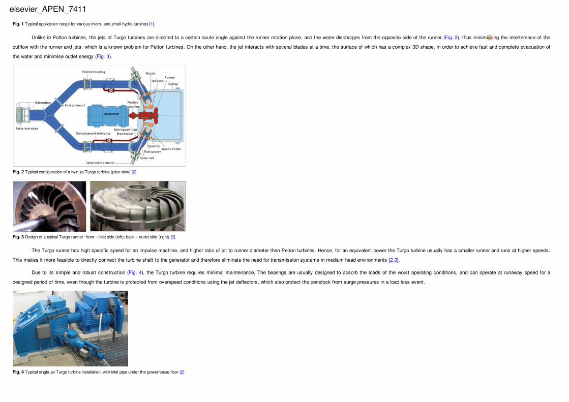
Unlike in Pelton turbines, the jets of Turgo turbines are directed to a certain acute angle against the runner rotation plane, and the water discharges from the opposite side of the runner (Fig. 2), thus minimiszing the interference of the
outflow with the runner and jets, which is a known problem for Pelton turbines. On the other hand, the jet interacts with several blades at a time, the surface of which has a complex 3D shape, in order to achieve fast and complete evacuation of
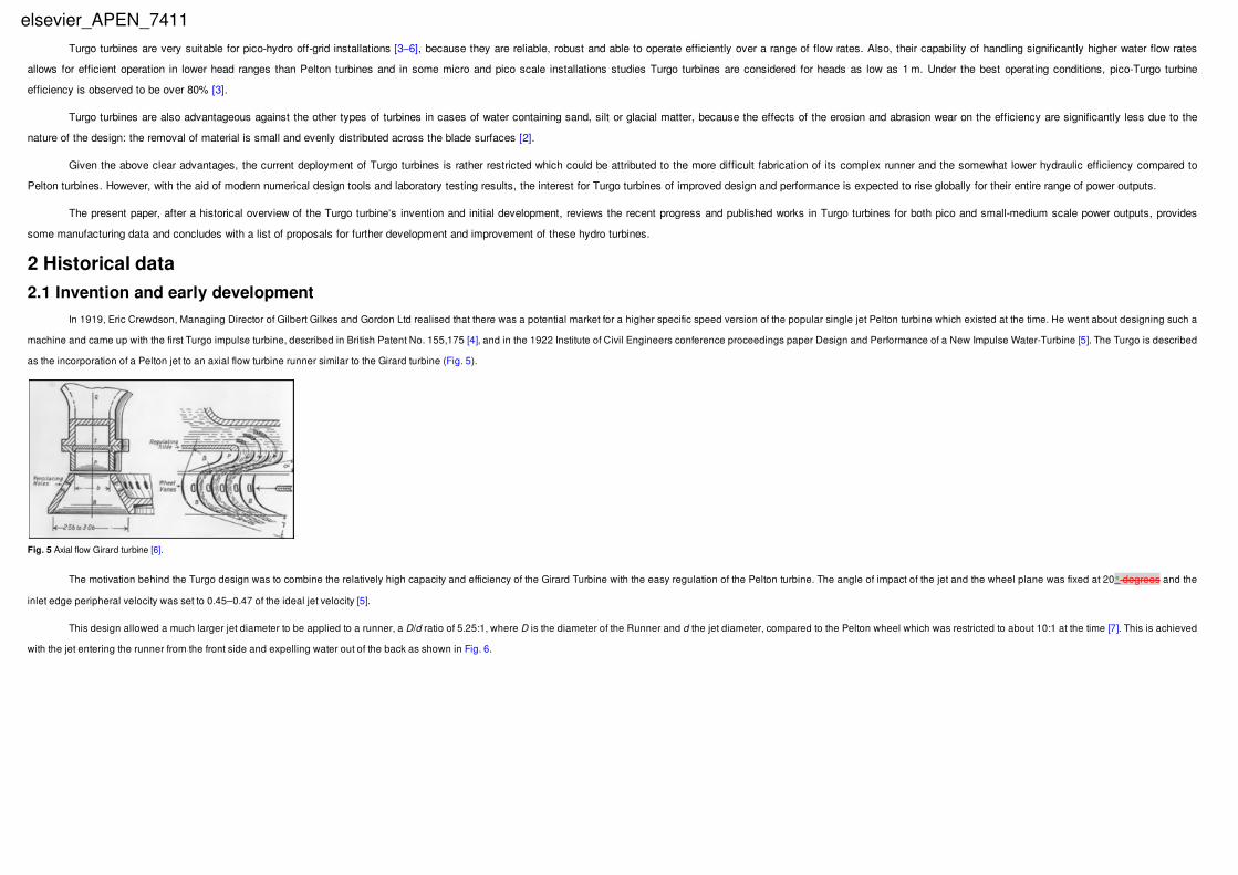
the water and minimise outlet energy (Fig. 3).
The Turgo runner has high specific speed for an impulse machine, and higher ratio of jet to runner diameter than Pelton turbines. Hence, for an equivalent power the Turgo turbine usually has a smaller runner and runs at higher speeds.
This makes it more feasible to directly connect the turbine shaft to the generator and therefore eliminate the need for transmission systems in medium head environments [2,3].
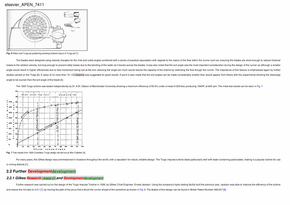
Due to its simple and robust construction (Fig. 4), the Turgo turbine requires minimal maintenance. The bearings are usually designed to absorb the loads of the worst operating conditions, and can operate at runaway speed for a
designed period of time, even though the turbine is protected from overspeed conditions using the jet deflectors, which also protect the penstock from surge pressures in a load loss event.
Fig. 1 Typical application range for various micro- and small-hydro turbines [1].
Fig. 2 Typical configuration of a twin jet Turgo turbine (plan view) [2].
Fig. 3 Design of a typical Turgo runner: front – inlet side (left); back – outlet side (right) [2].
Fig. 4 Typical single-jet Turgo turbine installation, with inlet pipe under the powerhouse floor [2].
elsevier_APEN_7411
Turgo turbines are very suitable for pico-hydro off-grid installations [3–6], because they are reliable, robust and able to operate efficiently over a range of flow rates. Also, their capability of handling significantly higher water flow rates
allows for efficient operation in lower head ranges than Pelton turbines and in some micro and pico scale installations studies Turgo turbines are considered for heads as low as 1 m. Under the best operating conditions, pico-Turgo turbine
efficiency is observed to be over 80% [3].
Turgo turbines are also advantageous against the other types of turbines in cases of water containing sand, silt or glacial matter, because the effects of the erosion and abrasion wear on the efficiency are significantly less due to the
nature of the design: the removal of material is small and evenly distributed across the blade surfaces [2].
Given the above clear advantages, the current deployment of Turgo turbines is rather restricted which could be attributed to the more difficult fabrication of its complex runner and the somewhat lower hydraulic efficiency compared to
Pelton turbines. However, with the aid of modern numerical design tools and laboratory testing results, the interest for Turgo turbines of improved design and performance is expected to rise globally for their entire range of power outputs.
The present paper, after a historical overview of the Turgo turbine’s invention and initial development, reviews the recent progress and published works in Turgo turbines for both pico and small-medium scale power outputs, provides
some manufacturing data and concludes with a list of proposals for further development and improvement of these hydro turbines.
2 Historical data2.1 Invention and early development
In 1919, Eric Crewdson, Managing Director of Gilbert Gilkes and Gordon Ltd realised that there was a potential market for a higher specific speed version of the popular single jet Pelton turbine which existed at the time. He went about designing such a
machine and came up with the first Turgo impulse turbine, described in British Patent No. 155,175 [4], and in the 1922 Institute of Civil Engineers conference proceedings paper Design and Performance of a New Impulse Water-Turbine [5]. The Turgo is described
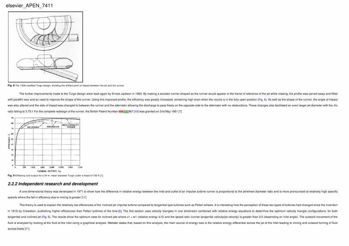
as the incorporation of a Pelton jet to an axial flow turbine runner similar to the Girard turbine (Fig. 5).
The motivation behind the Turgo design was to combine the relatively high capacity and efficiency of the Girard Turbine with the easy regulation of the Pelton turbine. The angle of impact of the jet and the wheel plane was fixed at 20° degrees and the
inlet edge peripheral velocity was set to 0.45–0.47 of the ideal jet velocity [5].
This design allowed a much larger jet diameter to be applied to a runner, a D/d ratio of 5.25:1, where D is the diameter of the Runner and d the jet diameter, compared to the Pelton wheel which was restricted to about 10:1 at the time [7]. This is achieved
with the jet entering the runner from the front side and expelling water out of the back as shown in Fig. 6.
Fig. 5 Axial flow Girard turbine [6].
elsevier_APEN_7411
The blades were designed using velocity triangles for the inlet and outlet angles combined with a series of practical assumption with regards to the nature of the flow within the runner such as: ensuring the blades are short enough to reduce frictional
losses to the relative velocity, but long enough to prevent eddy losses due to the bending of the water as it travels across the blades. It was also noted that the exit angle was the most important consideration during the design of the runner as although a smaller
angle would result in higher efficiencies due to less momentum being lost at the exit, reducing the angle too much would reduce the capacity of the turbine by restricting the flow though the runner. The importance of this feature is emphasised again by further
studies carried on the Turgo [8]. A value of no more than 10–15° degrees was suggested for good results. A point is also made that the exit angles can be made considerably smaller than would appear from theory with the experiments showing the discharge
angle to be courser than the exit angle of the blade [5].
The 1920 Turgo turbine was tested independently by Dr. A. H. Gibson of Manchester University showing a maximum efficiency of 83.5% under a head of 200 feet, producing 106HP, at 640 rpm. The initial test results can be seen in Fig. 7.
For many years, this Gilkes design was commissioned in locations throughout the world, with a reputation for robust, reliable design. The Turgo impulse turbine deals particularly well with water containing particulates, making it a popular turbine for use
in mining districts [7].
2.2 Further Developmentdevelopment
2.2.1 Gilkes Research research and Developmentdevelopment
Further research was carried out on the design of the Turgo Impulse Turbine in 1936, by Gilkes’ Chief Engineer, Ernest Jackson. Using the company’s hydro testing facility built the previous year, Jackson was able to improve the efficiency of the turbine
and reduce the D/d ratio to 4.5:1 [7], by moving the path of the jet so that it struck the runner ahead of the centreline as shown in Fig. 8. The details of this design can be found in British Patent Number 468,557 [9].
Fig. 6 Pelton and Turgo jet positioning showing inclined nature of Turgo jet [7].
Fig. 7 Test results from 1920 Crewdson Turgo design carried out at Afon Calettwr [5].
elsevier_APEN_7411
The further improvements made to the Turgo design were lead again by Ernest Jackson in 1960. By making a wooden runner shaped as the runner would appear in the frame of reference of the jet while rotating, the profile was carved away and filled
with paraffin wax and so used to improve the shape of the runner. Using this improved profile, the efficiency was greatly increased, remaining high even when the nozzle is in the fully open position (Fig. 9). As well as the shape of the runner, the angle of impact
was also altered and the side of impact was changed to between the runner and the alternator allowing the discharge to pass freely on the opposite side to the alternator with no obstructions. These changes also facilitated an even larger jet diameter with the D/d
ratio falling to 3.75:1 For the complete redesign of the runner, the British Patent Number 938 938,967 [10] was granted on 2nd May 1961 [7].
2.2.2 Independent research and development
A one-dimensional theory was developed in 1971 to show how the difference in relative energy between the inlet and outlet of an impulse turbine runner is proportional to the jet/wheel diameter ratio and is more pronounced at relatively high specific
speeds where the fall in efficiency due to mixing is greater [11].
This theory is used to explain the relatively low efficiencies of the ’inclined jet’ impulse turbine compared to tangential type turbines such as Pelton wheels. It is interesting how the perception of these two types of turbines had changed since the invention
in 1919 by Crewdson, publishing higher efficiencies than Pelton turbines of the time [5]. The first section uses velocity triangles in one dimension combined with relative energy equations to determine the optimum velocity triangle configurations, for both
tangential and inclined jet (Fig. 8). The results show the optimum case for inclined jets where v1 = w1 (relative energy is 0) and the speed ratio (runner tangential velocity/jet velocity) is greater than 0.5 (depending on inlet angle). The outward movement of the
fluid is analysed by looking at the fluid at the inlet using a graphical analysis. Webster states that, based on this analysis, the main source of energy loss is the relative energy differential across the jet at the inlet leading to mixing and outward turning of fluid
across blade [11].
Fig. 8 The 1936 modified Turgo design, showing the shifted point of impact between the jet and the runner.
Fig. 9 Efficiency and output for a 24 in. mean diameter Turgo under a head of 750 ft [7].
elsevier_APEN_7411

Further research was carried out in 1972, looking at the flow patterns relating to jet-type turbines using both graphical and experimental techniques. The paper looks at the jet cross sections cut out by Pelton and Turgo turbines and how they interact with
various runners. A dimensional analysis is carried out first followed by experimental measurements of flow patterns relating to different rectangular and semi-circular cross sections [8].
Further work was carried out in 1973 where the flow at the outlet of a Turgo runner is analysed experimentally, showing the outlet velocity and flow distributions at various locations and comparing these to theoretical conditions at the inlet. The injector is
mounted vertically in this experimental setup, with the runner shaft inclined at the design angle. Fig. 10 shows the distribution of absolute outlet velocities calculated by measuring the position of droplets with a stroboscope at the intersection points of a grid
covering the outlet flow region. The outlet flow region is defined by taking angles from 000° to -125°0, with 0°0 parallel to the jet axis in the plane parallel to the runner face. These angles are measured at 9 equidistant positions (1–9) from the hub to the ring along
the curved rim of the bucket. This three dimensional region is plotted in two dimensions by developing the curved rim of the bucket into a straight line [12].
These experimental results show a much higher degree of lateral spreading than theory states which may be a result of viscous forces within the fluid. The author shows some improvements are possible by moving the jet radially outwards at the inlet
and carried out tests showing a 4% increase in efficiency [12].
3 Recent development and applicationsTurgo turbine applications can be found today in two main operating regions, Micro range and Small-Medium range. Micro hydro turbines, ranging from very small power, 100–200 W (also known as pico-hydro turbines) up to about
100–300 kW [13], are used in remote, non-interconnected locations to provide power for small rural communities or small factories. Low construction cost and easy maintenance are the principal desirable characteristics for these turbines,
leading to relatively simplified blade designs (Fig. 11), that can be shaped from a half symmetric part of a Pelton bucket to a simple tablespoon. As a result, their hydrodynamic design is not optimum and the hydraulic efficiency of the runners is
relatively low.
Fig. 10 Experimental absolute velocities at the outlet of the Turgo runner in feet/s [12].
elsevier_APEN_7411
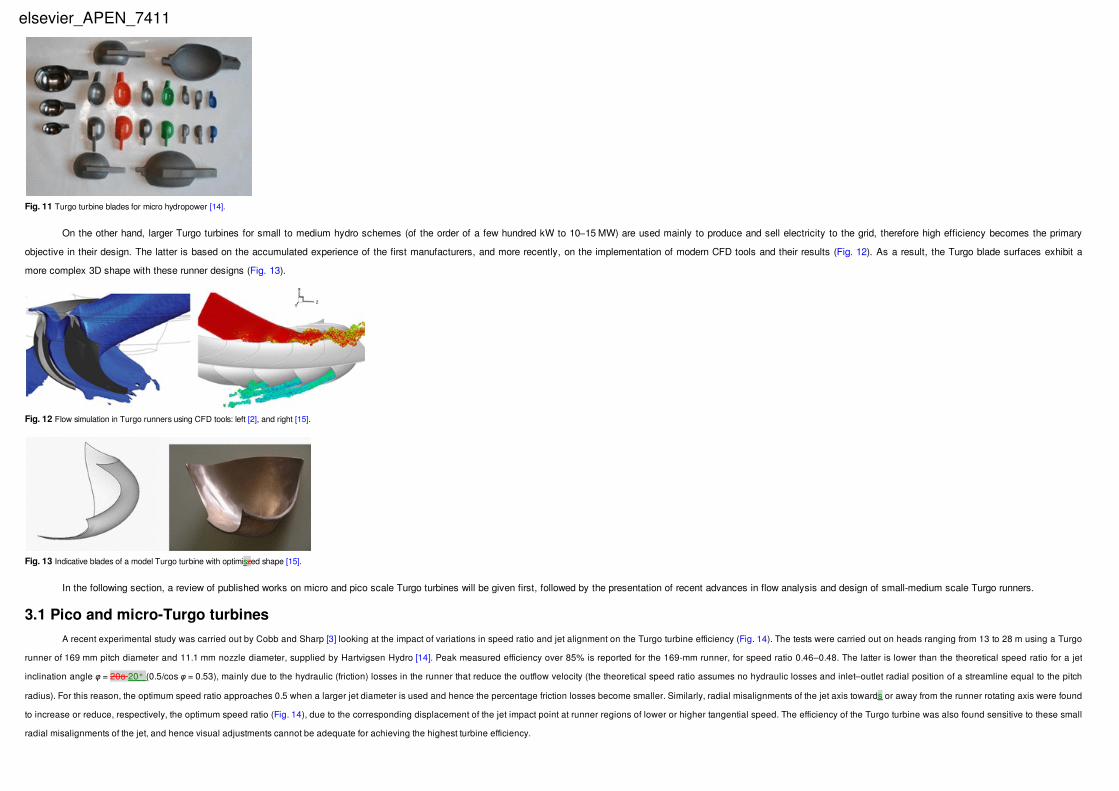
On the other hand, larger Turgo turbines for small to medium hydro schemes (of the order of a few hundred kW to 10–15 MW) are used mainly to produce and sell electricity to the grid, therefore high efficiency becomes the primary
objective in their design. The latter is based on the accumulated experience of the first manufacturers, and more recently, on the implementation of modern CFD tools and their results (Fig. 12). As a result, the Turgo blade surfaces exhibit a
more complex 3D shape with these runner designs (Fig. 13).
In the following section, a review of published works on micro and pico scale Turgo turbines will be given first, followed by the presentation of recent advances in flow analysis and design of small-medium scale Turgo runners.
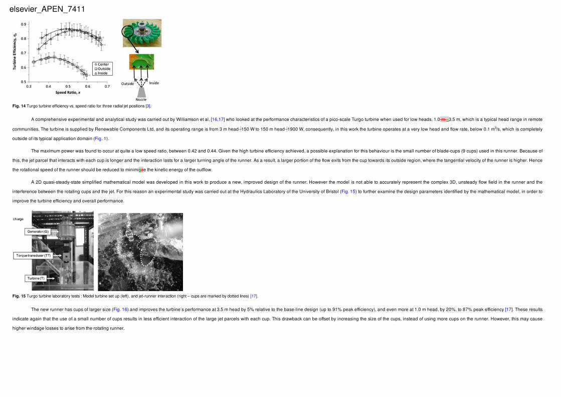
3.1 Pico and micro-Turgo turbinesA recent experimental study was carried out by Cobb and Sharp [3] looking at the impact of variations in speed ratio and jet alignment on the Turgo turbine efficiency (Fig. 14). The tests were carried out on heads ranging from 13 to 28 m using a Turgo
runner of 169 mm pitch diameter and 11.1 mm nozzle diameter, supplied by Hartvigsen Hydro [14]. Peak measured efficiency over 85% is reported for the 169-mm runner, for speed ratio 0.46–0.48. The latter is lower than the theoretical speed ratio for a jet
inclination angle φ = 20o 20° (0.5/cos φ = 0.53), mainly due to the hydraulic (friction) losses in the runner that reduce the outflow velocity (the theoretical speed ratio assumes no hydraulic losses and inlet–outlet radial position of a streamline equal to the pitch
radius). For this reason, the optimum speed ratio approaches 0.5 when a larger jet diameter is used and hence the percentage friction losses become smaller. Similarly, radial misalignments of the jet axis towards or away from the runner rotating axis were found
to increase or reduce, respectively, the optimum speed ratio (Fig. 14), due to the corresponding displacement of the jet impact point at runner regions of lower or higher tangential speed. The efficiency of the Turgo turbine was also found sensitive to these small
radial misalignments of the jet, and hence visual adjustments cannot be adequate for achieving the highest turbine efficiency.
Fig. 11 Turgo turbine blades for micro hydropower [14].
Fig. 12 Flow simulation in Turgo runners using CFD tools: left [2], and right [15].
Fig. 13 Indicative blades of a model Turgo turbine with optimiszed shape [15].
elsevier_APEN_7411
A comprehensive experimental and analytical study was carried out by Williamson et al. [16,17] who looked at the performance characteristics of a pico-scale Turgo turbine when used for low heads, 1.0 m-–3.5 m, which is a typical head range in remote
communities. The turbine is supplied by Renewable Components Ltd, and its operating range is from 3 m head- 150 W to 150 m head- 1900 W, consequently, in this work the turbine operates at a very low head and flow rate, below 0.1 m3/s, which is completely
outside of its typical application domain (Fig. 1).
The maximum power was found to occur at quite a low speed ratio, between 0.42 and 0.44. Given the high turbine efficiency achieved, a possible explanation for this behaviour is the small number of blade-cups (9 cups) used in this runner. Because of
this, the jet parcel that interacts with each cup is longer and the interaction lasts for a larger turning angle of the runner. As a result, a larger portion of the flow exits from the cup towards its outside region, where the tangential velocity of the runner is higher. Hence
the rotational speed of the runner should be reduced to minimisze the kinetic energy of the outflow.
A 2D quasi-steady-state simplified mathematical model was developed in this work to produce a new, improved design of the runner. However the model is not able to accurately represent the complex 3D, unsteady flow field in the runner and the
interference between the rotating cups and the jet. For this reason an experimental study was carried out at the Hydraulics Laboratory of the University of Bristol (Fig. 15) to further examine the design parameters identified by the mathematical model, in order to
improve the turbine efficiency and overall performance.
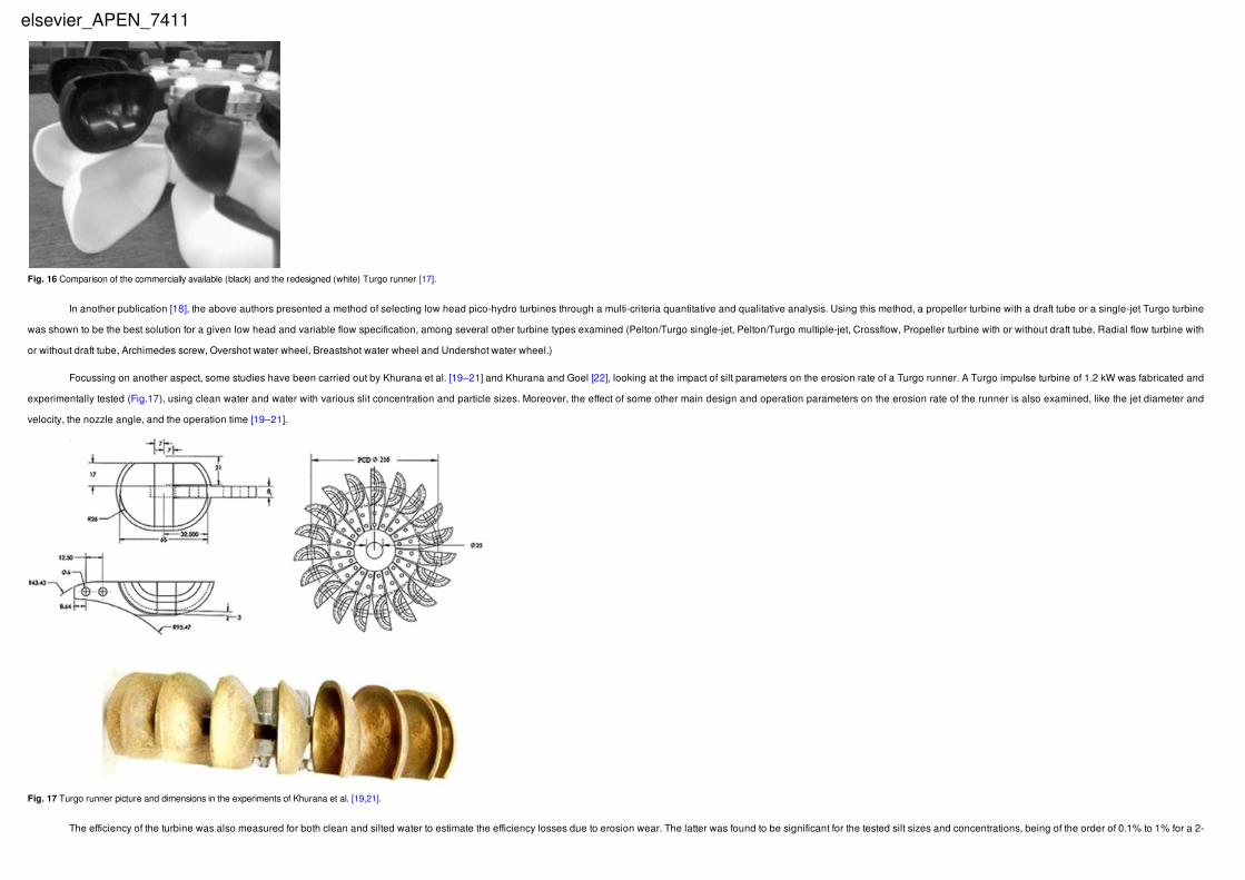
The new runner has cups of larger size (Fig. 16) and improves the turbine’s performance at 3.5 m head by 5% relative to the base-line design (up to 91% peak efficiency), and even more at 1.0 m head, by 20%, to 87% peak efficiency [17]. These results
indicate again that the use of a small number of cups results in less efficient interaction of the large jet parcels with each cup. This drawback can be offset by increasing the size of the cups, instead of using more cups on the runner. However, this may cause
higher windage losses to arise from the rotating runner.
Fig. 14 Turgo turbine efficiency vs. speed ratio for three radial jet positions [3].
Fig. 15 Turgo turbine laboratory tests : Model turbine set up (left), and jet-runner interaction (right – cups are marked by dotted lines) [17].
elsevier_APEN_7411
In another publication [18], the above authors presented a method of selecting low head pico-hydro turbines through a multi-criteria quantitative and qualitative analysis. Using this method, a propeller turbine with a draft tube or a single-jet Turgo turbine
was shown to be the best solution for a given low head and variable flow specification, among several other turbine types examined (Pelton/Turgo single-jet, Pelton/Turgo multiple-jet, Crossflow, Propeller turbine with or without draft tube, Radial flow turbine with
or without draft tube, Archimedes screw, Overshot water wheel, Breastshot water wheel and Undershot water wheel.)
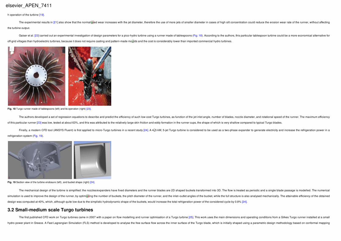
Focussing on another aspect, some studies have been carried out by Khurana et al. [19–21] and Khurana and Goel [22], looking at the impact of silt parameters on the erosion rate of a Turgo runner. A Turgo impulse turbine of 1.2 kW was fabricated and
experimentally tested (Fig.17), using clean water and water with various slit concentration and particle sizes. Moreover, the effect of some other main design and operation parameters on the erosion rate of the runner is also examined, like the jet diameter and
velocity, the nozzle angle, and the operation time [19–21].
The efficiency of the turbine was also measured for both clean and silted water to estimate the efficiency losses due to erosion wear. The latter was found to be significant for the tested silt sizes and concentrations, being of the order of 0.1% to 1% for a 2-
Fig. 16 Comparison of the commercially available (black) and the redesigned (white) Turgo runner [17].
Fig. 17 Turgo runner picture and dimensions in the experiments of Khurana et al. [19,21].
elsevier_APEN_7411
h operation of the turbine [19].
The experimental results in [21] also show that the normaliszed wear increases with the jet diameter, therefore the use of more jets of smaller diameter in cases of high silt concentration could reduce the erosion wear rate of the runner, without affecting
the turbine output.
Gaiser et al. [23] carried out an experimental investigation of design parameters for a pico-hydro turbine using a runner made of tablespoons (Fig. 18). According to the authors, this particular tablespoon turbine could be a more economical alternative for
off-grid villages than hydroelectric turbines, because it does not require casting and pattern-made moulds and the cost is considerably lower than imported commercial hydro turbines.
The authors developed a set of regression equations to describe and predict the efficiency of such low-cost Turgo turbines, as function of the jet inlet angle, number of blades, nozzle diameter, and rotational speed of the runner. The maximum efficiency
of this particular runner [23] was low, tested at about 63%, and this was attributed to the relatively large skin friction and eddy formation in the runner cups, the shape of which is very shallow compared to typical Turgo blades.
Finally, a modern CFD tool (ANSYS Fluent) is first applied to micro-Turgo turbines in a recent study [24]. A 4,.5 kW, 5-jet Turgo turbine is considered to be used as a two-phase expander to generate electricity and increase the refrigeration power in a
refrigeration system (Fig. 19).
The mechanical design of the turbine is simplified: the nozzles/expanders have fixed diameters and the runner blades are 2D shaped buckets transformed into 3D. The flow is treated as periodic and a single blade passage is modelled. The numerical
simulation is used to improve the design of the runner, by optimiszing the number of buckets, the pitch diameter of the runner, and the inlet–outlet angles of the bucket, while the full structure is also analysed mechanically. The attainable efficiency of the obtained
design was computed at 40%, which, although quite low due to the simplistic hydrodynamic shape of the buckets, would increase the total refrigeration power of the considered cycle by 0.8% [24].
3.2 Small-medium scale Turgo turbinesThe first published CFD work on Turgo turbines came in 2007 with a paper on flow modelling and runner optimisation of a Turgo turbine [25]. This work uses the main dimensions and operating conditions from a Gilkes Turgo runner installed at a small
hydro power plant in Greece. A Fast Lagrangian Simulation (FLS) method is developed to analyse the free surface flow across the inner surface of the Turgo blade, which is initially shaped using a parametric design methodology based on conformal mapping
Fig. 18 Turgo runner made of tablespoons (left) and its operation (right) [23].
Fig. 19 Section view of the turbine enclosure (left), and bucket shape (right) [24].
elsevier_APEN_7411
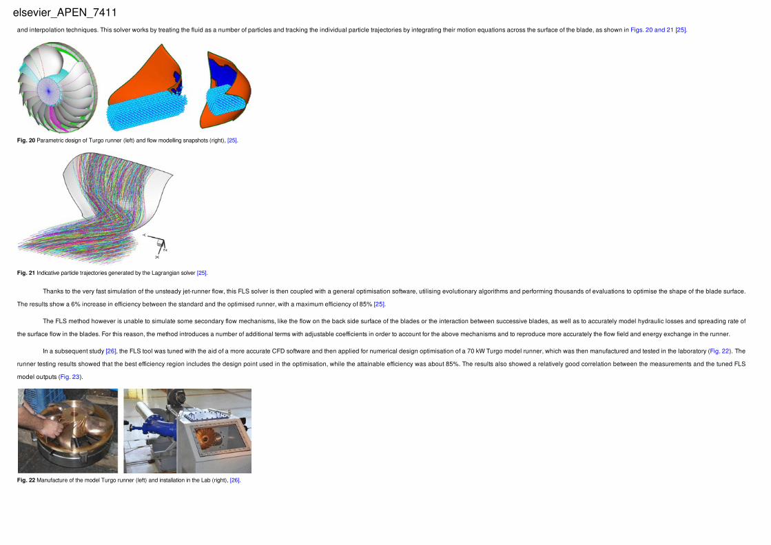
and interpolation techniques. This solver works by treating the fluid as a number of particles and tracking the individual particle trajectories by integrating their motion equations across the surface of the blade, as shown in Figs. 20 and 21 [25].
Thanks to the very fast simulation of the unsteady jet-runner flow, this FLS solver is then coupled with a general optimisation software, utilising evolutionary algorithms and performing thousands of evaluations to optimise the shape of the blade surface.
The results show a 6% increase in efficiency between the standard and the optimised runner, with a maximum efficiency of 85% [25].
The FLS method however is unable to simulate some secondary flow mechanisms, like the flow on the back side surface of the blades or the interaction between successive blades, as well as to accurately model hydraulic losses and spreading rate of
the surface flow in the blades. For this reason, the method introduces a number of additional terms with adjustable coefficients in order to account for the above mechanisms and to reproduce more accurately the flow field and energy exchange in the runner.
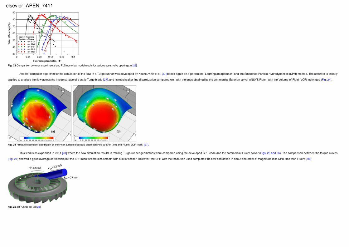
In a subsequent study [26], the FLS tool was tuned with the aid of a more accurate CFD software and then applied for numerical design optimisation of a 70 kW Turgo model runner, which was then manufactured and tested in the laboratory (Fig. 22). The
runner testing results showed that the best efficiency region includes the design point used in the optimisation, while the attainable efficiency was about 85%. The results also showed a relatively good correlation between the measurements and the tuned FLS
model outputs (Fig. 23).
Fig. 20 Parametric design of Turgo runner (left) and flow modelling snapshots (right), [25].
Fig. 21 Indicative particle trajectories generated by the Lagrangian solver [25].
Fig. 22 Manufacture of the model Turgo runner (left) and installation in the Lab (right), [26].
elsevier_APEN_7411
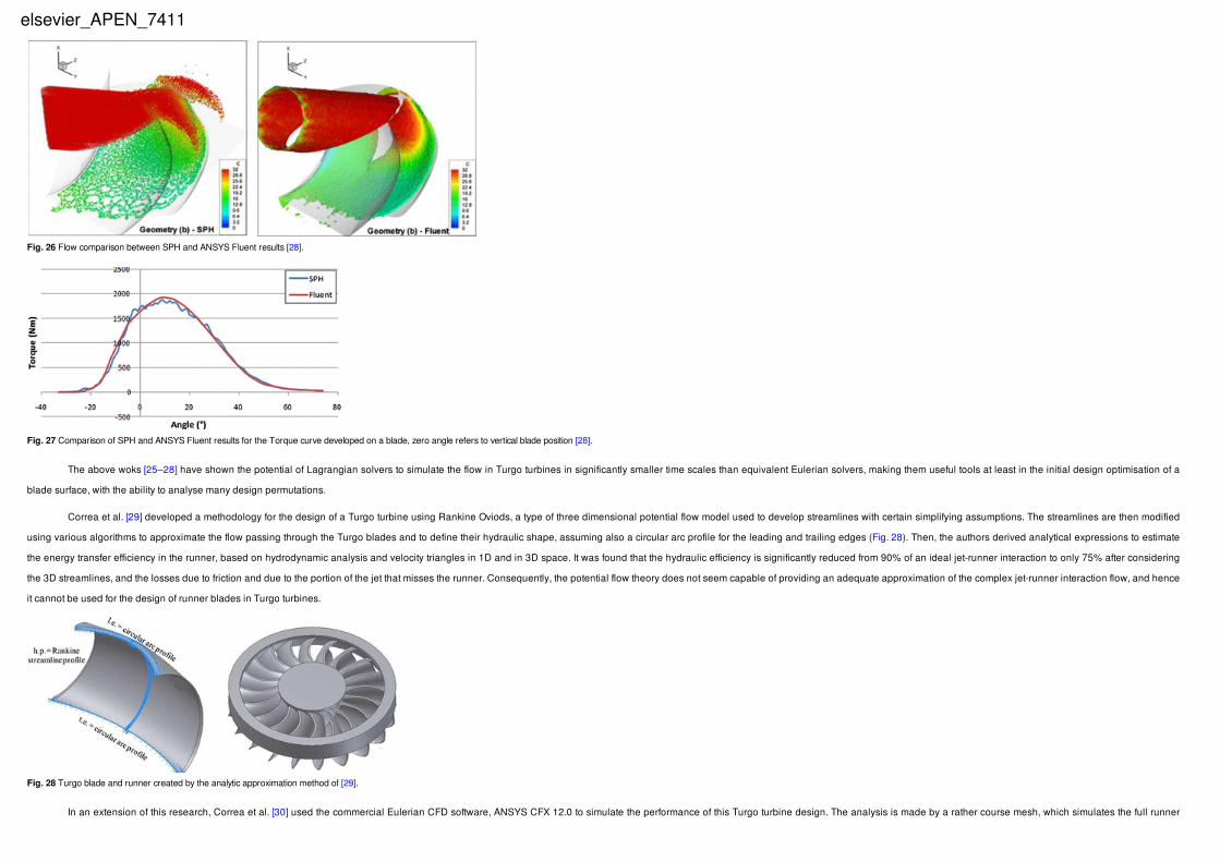
Another computer algorithm for the simulation of the flow in a Turgo runner was developed by Koukouvinis et al. [27] based again on a particulate, Lagrangian approach, and the Smoothed Particle Hydrodynamics (SPH) method. The software is initially
applied to analyse the flow across the inside surface of a static Turgo blade [27], and its results after fine discretization compared well with the ones obtained by the commercial Eulerian solver ANSYS Fluent with the Volume-of-Fluid (VOF) technique (Fig. 24).
This work was expanded in 2011 [28] where the flow simulation results in rotating Turgo runner geometries were compared using the developed SPH code and the commercial Fluent solver (Figs. 25 and 26). The comparison between the torque curves
(Fig. 27) showed a good average correlation, but the SPH results were less smooth with a lot of scatter. However, the SPH with the resolution used completes the flow simulation in about one order of magnitude less CPU time than Fluent [28].
Fig. 23 Comparison between experimental and FLS numerical model results for various spear valve openings, α [26].
Fig. 24 Pressure coefficient distribution on the inner surface of a static blade obtained by SPH (left) and Fluent-VOF (right) [27].
Fig. 25 Jet-runner set up [28].
elsevier_APEN_7411
The above woks [25–28] have shown the potential of Lagrangian solvers to simulate the flow in Turgo turbines in significantly smaller time scales than equivalent Eulerian solvers, making them useful tools at least in the initial design optimisation of a
blade surface, with the ability to analyse many design permutations.
Correa et al. [29] developed a methodology for the design of a Turgo turbine using Rankine Oviods, a type of three dimensional potential flow model used to develop streamlines with certain simplifying assumptions. The streamlines are then modified
using various algorithms to approximate the flow passing through the Turgo blades and to define their hydraulic shape, assuming also a circular arc profile for the leading and trailing edges (Fig. 28). Then, the authors derived analytical expressions to estimate
the energy transfer efficiency in the runner, based on hydrodynamic analysis and velocity triangles in 1D and in 3D space. It was found that the hydraulic efficiency is significantly reduced from 90% of an ideal jet-runner interaction to only 75% after considering
the 3D streamlines, and the losses due to friction and due to the portion of the jet that misses the runner. Consequently, the potential flow theory does not seem capable of providing an adequate approximation of the complex jet-runner interaction flow, and hence
it cannot be used for the design of runner blades in Turgo turbines.
In an extension of this research, Correa et al. [30] used the commercial Eulerian CFD software, ANSYS CFX 12.0 to simulate the performance of this Turgo turbine design. The analysis is made by a rather course mesh, which simulates the full runner
Fig. 26 Flow comparison between SPH and ANSYS Fluent results [28].
Fig. 27 Comparison of SPH and ANSYS Fluent results for the Torque curve developed on a blade, zero angle refers to vertical blade position [28].
Fig. 28 Turgo blade and runner created by the analytic approximation method of [29].
elsevier_APEN_7411
with 20 blades as well as the casing, with just over 2 million elements, corresponding to roughly 100 k elements per blade passage.
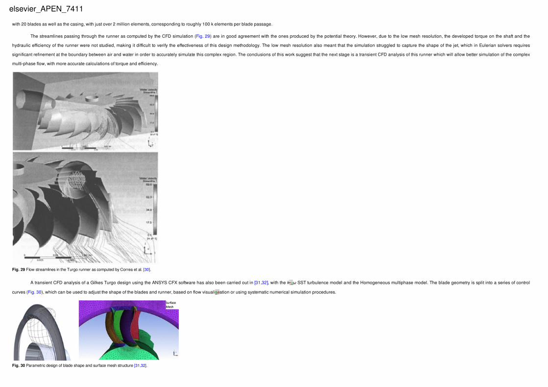
The streamlines passing through the runner as computed by the CFD simulation (Fig. 29) are in good agreement with the ones produced by the potential theory. However, due to the low mesh resolution, the developed torque on the shaft and the
hydraulic efficiency of the runner were not studied, making it difficult to verify the effectiveness of this design methodology. The low mesh resolution also meant that the simulation struggled to capture the shape of the jet, which in Eulerian solvers requires
significant refinement at the boundary between air and water in order to accurately simulate this complex region. The conclusions of this work suggest that the next stage is a transient CFD analysis of this runner which will allow better simulation of the complex
multi-phase flow, with more accurate calculations of torque and efficiency.
A transient CFD analysis of a Gilkes Turgo design using the ANSYS CFX software has also been carried out in [31,32], with the k-–ω SST turbulence model and the Homogeneous multiphase model. The blade geometry is split into a series of control
curves (Fig. 30), which can be used to adjust the shape of the blades and runner, based on flow visualiszation or using systematic numerical simulation procedures.
Fig. 29 Flow streamlines in the Turgo runner as computed by Correa et al. [30].
Fig. 30 Parametric design of blade shape and surface mesh structure [31,32].
elsevier_APEN_7411
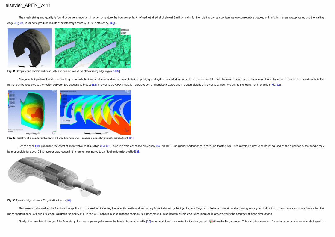
The mesh sizing and quality is found to be very important in order to capture the flow correctly. A refined tetrahedral of almost 3 million cells, for the rotating domain containing two consecutive blades, with inflation layers wrapping around the trailing
edge (Fig. 31) is found to produce results of satisfactory accuracy (±1% in efficiency, [32]).
Also, a technique to calculate the total torque on both the inner and outer surface of each blade is applied, by adding the computed torque data on the inside of the first blade and the outside of the second blade, by which the simulated flow domain in the
runner can be restricted to the region between two successive blades [32]. The complete CFD simulation provides comprehensive pictures and important details of the complex flow field during the jet-runner interaction (Fig. 32).
Benzon et al. [33], examined the effect of spear valve configuration (Fig. 33), using injectors optimised previously [34], on the Turgo runner performance, and found that the non-uniform velocity profile of the jet caused by the presence of the needle may
be responsible for about 0.8% more energy losses in the runner, compared to an ideal uniform jet profile [33].
This research showed for the first time the application of a real jet, including the velocity profile and secondary flows induced by the injector, to a Turgo and Pelton runner simulation, and gives a good indication of how these secondary flows affect the
runner performance. Although this work validates the ability of Eulerian CFD solvers to capture these complex flow phenomena, experimental studies would be required in order to verify the accuracy of these simulations.
Finally, the possible blockage of the flow along the narrow passage between the blades is considered in [35] as an additional parameter for the design optimiszation of a Turgo runner. This study is carried out for various runners in an extended specific
Fig. 31 Computational domain and mesh (left), and detailed view at the blades trailing edge region [31,32].
Fig. 32 Indicative CFD results for the flow in a Turgo turbine runner: Pressure profiles (left); velocity profiles (right) [31].
Fig. 33 Typical configuration of a Turgo turbine injector [33].
elsevier_APEN_7411

speed range, and showed that the attainable efficiency is higher for low to medium specific speeds, whereas it reduces drastically for high specific speed runners. For given site characteristics (water flow rate and head), such runners have relatively small pitch
diameter and high rotating speed, while their blades become shorter (small wrap angle) in order to reduce the flow blockage effects, and hence they are less efficient to transfer the fluid energy. Moreover, it was observed that in that case the axial and radial
velocity components of the exit flow velocity become significant, and hence the outflow kinetic energy losses increase. For the same reason, the optimum speed ratio for high specific speed runners does not depend only on the tangential velocity components,
and it may take values even above the theoretical ones (almost 0.6, compared to theoretical 0.55 for a jet inclination angle of 25° deg [35]).
3.3 Turgo turbine manufacturersThe construction of a Turgo runner is more difficult than a Pelton, and the blades of the runner are generally more fragile than Pelton buckets. Moreover, the hydraulic efficiency of a Turgo runner is much more sensitive to the geometric design of the
blades, which have a complex 3D shape. Hence, a non-optimum runner design may attain considerably lower efficiencies than a corresponding conventional Pelton runner.
For these reasons, until the end of the 20th century, Turgo turbines for small hydropower plants, ranging from a few hundred kW up to 10 MW, were constructed and installed only by Gilbert Gilkes and Gordon Ltd who owned the patent rights.
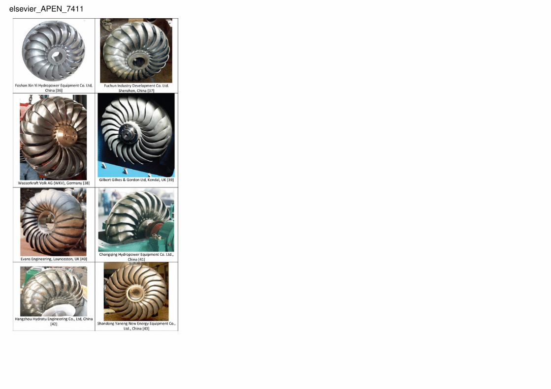
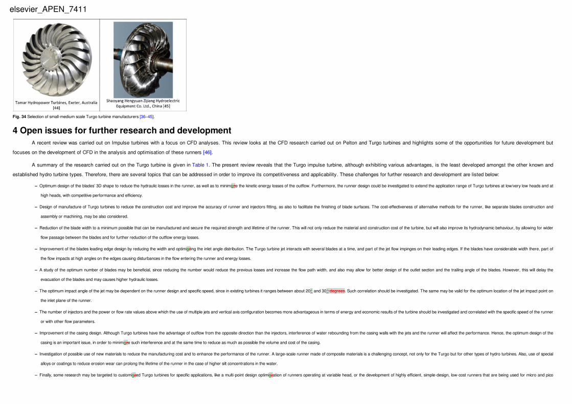
After the expiration of this patent [10] in 1983, several other manufacturers, most of which are based in China, have started to include small and medium Turgo turbines (up to 10–15 MW) in their product range. Most of these designs are based on the
original Gilkes Turgo design, and hence the various runners are similar, though there are clear differences, as shown in Fig. 34. According to the computational results from flow simulation, these observable differences may lead to considerable variations in
efficiency. The latter is not usually provided by the manufacturers, but in some cases it can be computed through the head, flow rate and power output data, and is found to range between 75% and 85%, depending mainly on the power (higher for larger hydro
turbines), but also on the specific manufacturer. Most of these manufacturers do not implement CFD in their runner design. Therefore, there is a significant margin for further improvements in performance and efficiency of their products.
elsevier_APEN_7411
elsevier_APEN_7411
4 Open issues for further research and developmentA recent review was carried out on Impulse turbines with a focus on CFD analyses. This review looks at the CFD research carried out on Pelton and Turgo turbines and highlights some of the opportunities for future development but
focuses on the development of CFD in the analysis and optimisation of these runners [46].
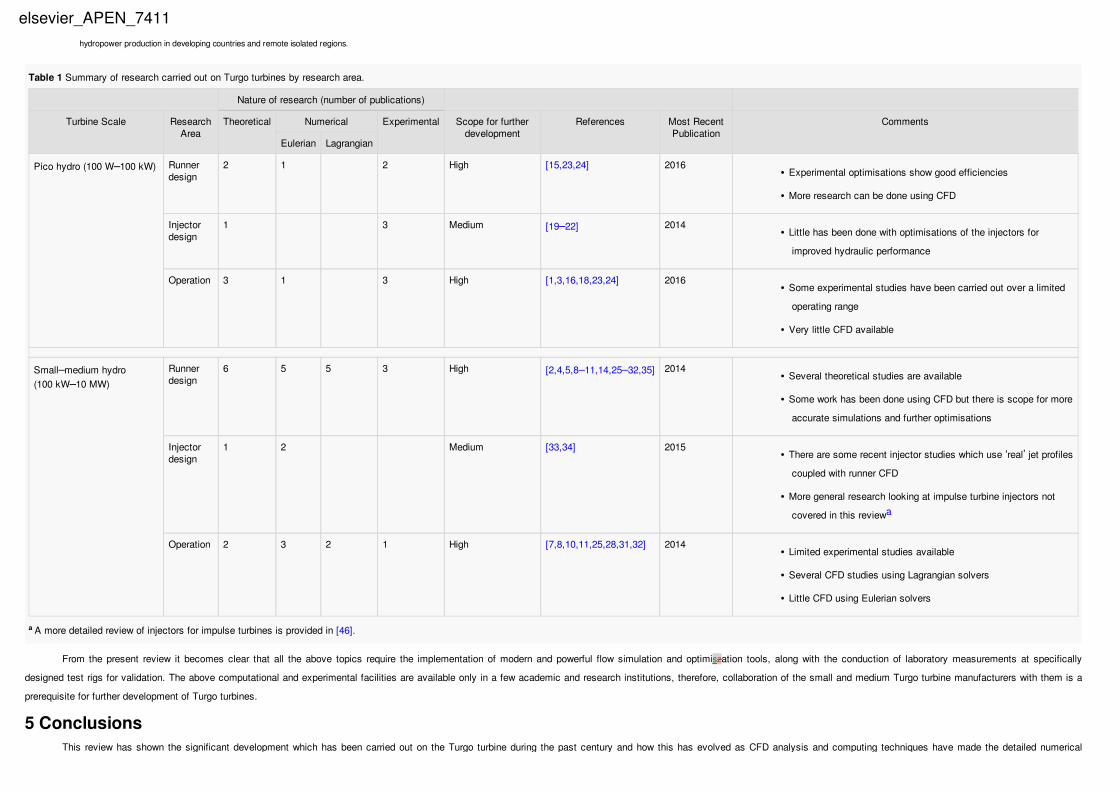
A summary of the research carried out on the Turgo turbine is given in Table 1. The present review reveals that the Turgo impulse turbine, although exhibiting various advantages, is the least developed amongst the other known and
established hydro turbine types. Therefore, there are several topics that can be addressed in order to improve its competitiveness and applicability. These challenges for further research and development are listed below:
– Optimum design of the blades’ 3D shape to reduce the hydraulic losses in the runner, as well as to minimisze the kinetic energy losses of the outflow. Furthermore, the runner design could be investigated to extend the application range of Turgo turbines at low/very low heads and at
high heads, with competitive performance and efficiency.
– Design of manufacture of Turgo turbines to reduce the construction cost and improve the accuracy of runner and injectors fitting, as also to facilitate the finishing of blade surfaces. The cost-effectiveness of alternative methods for the runner, like separate blades construction and
assembly or machining, may be also considered.
– Reduction of the blade width to a minimum possible that can be manufactured and secure the required strength and lifetime of the runner. This will not only reduce the material and construction cost of the turbine, but will also improve its hydrodynamic behaviour, by allowing for wider
flow passage between the blades and for further reduction of the outflow energy losses.
– Improvement of the blades leading edge design by reducing the width and optimiszing the inlet angle distribution. The Turgo turbine jet interacts with several blades at a time, and part of the jet flow impinges on their leading edges. If the blades have considerable width there, part of
the flow impacts at high angles on the edges causing disturbances in the flow entering the runner and energy losses.
– A study of the optimum number of blades may be beneficial, since reducing the number would reduce the previous losses and increase the flow path width, and also may allow for better design of the outlet section and the trailing angle of the blades. However, this will delay the
evacuation of the blades and may causes higher hydraulic losses.
– The optimum impact angle of the jet may be dependent on the runner design and specific speed, since in existing turbines it ranges between about 20° and 30° degrees. Such correlation should be investigated. The same may be valid for the optimum location of the jet impact point on
the inlet plane of the runner.
– The number of injectors and the power or flow rate values above which the use of multiple jets and vertical axis configuration becomes more advantageous in terms of energy and economic results of the turbine should be investigated and correlated with the specific speed of the runner
or with other flow parameters.
– Improvement of the casing design. Although Turgo turbines have the advantage of outflow from the opposite direction than the injectors, interference of water rebounding from the casing walls with the jets and the runner will affect the performance. Hence, the optimum design of the
casing is an important issue, in order to minimisze such interference and at the same time to reduce as much as possible the volume and cost of the casing.
– Investigation of possible use of new materials to reduce the manufacturing cost and to enhance the performance of the runner. A large-scale runner made of composite materials is a challenging concept, not only for the Turgo but for other types of hydro turbines. Also, use of special
alloys or coatings to reduce erosion wear can prolong the lifetime of the runner in the case of higher silt concentrations in the water.
– Finally, some research may be targeted to customiszed Turgo turbines for specific applications, like a multi-point design optimiszation of runners operating at variable head, or the development of highly efficient, simple-design, low-cost runners that are being used for micro and pico
Fig. 34 Selection of small-medium scale Turgo turbine manufacturers [36–45].
elsevier_APEN_7411
hydropower production in developing countries and remote isolated regions.
Table 1 Summary of research carried out on Turgo turbines by research area.
Nature of research (number of publications)
Turbine Scale ResearchArea
Theoretical Numerical Experimental Scope for furtherdevelopment
References Most RecentPublication
Comments
Eulerian Lagrangian
Pico hydro (100 W–100 kW) Runnerdesign
2 1 2 High [15,23,24] 2016• Experimental optimisations show good efficiencies
• More research can be done using CFD
Injectordesign
1 3 Medium [19–22] 2014• Little has been done with optimisations of the injectors for
improved hydraulic performance
Operation 3 1 3 High [1,3,16,18,23,24] 2016• Some experimental studies have been carried out over a limited
operating range
• Very little CFD available
Small–medium hydro(100 kW–10 MW)
Runnerdesign
6 5 5 3 High [2,4,5,8–11,14,25–32,35] 2014• Several theoretical studies are available
• Some work has been done using CFD but there is scope for more
accurate simulations and further optimisations
Injectordesign
1 2 Medium [33,34] 2015• There are some recent injector studies which use ‘real’ jet profiles
coupled with runner CFD
• More general research looking at impulse turbine injectors not
covered in this reviewa
Operation 2 3 2 1 High [7,8,10,11,25,28,31,32] 2014• Limited experimental studies available
• Several CFD studies using Lagrangian solvers
• Little CFD using Eulerian solvers
a A more detailed review of injectors for impulse turbines is provided in [46].
From the present review it becomes clear that all the above topics require the implementation of modern and powerful flow simulation and optimiszation tools, along with the conduction of laboratory measurements at specifically
designed test rigs for validation. The above computational and experimental facilities are available only in a few academic and research institutions, therefore, collaboration of the small and medium Turgo turbine manufacturers with them is a
prerequisite for further development of Turgo turbines.
5 ConclusionsThis review has shown the significant development which has been carried out on the Turgo turbine during the past century and how this has evolved as CFD analysis and computing techniques have made the detailed numerical
elsevier_APEN_7411
This review has shown the significant development which has been carried out on the Turgo turbine during the past century and how this has evolved as CFD analysis and computing techniques have made the detailed numerical
calculation of the associated flows possible.
It has shown that although we are beginning to use CFD for the analysis of this complex case, it has yet to be utilised to its full potential. A complete analysis of the Turgo turbine using CFD, capturing the high speed, highly turbulent,
multiphase flow across the blades is yet to be carried out. Research on Pelton turbines have shown that using Eulerian techniques it is possible to develop a CFD model which can accurately describe the flow across the Turgo runner, calculate
the torque developed and the efficiency, and capture small changes in the design in a reasonable timescale.
With the continual improvements to computer processing speeds and CFD codes, these complex simulations are being run in shorter times and it is predicted that the future development of the Turgo turbine will be based around these
numerical analyses.
Combining the above computer tools with laboratory testing of Turgo turbine models, several targets for further design improvement may be realised, and can be expected to enhance the performance, application range and
competitiveness of Turgo turbines.
References[1]
Fraenkel P, Paish O, Bokalders V, Harvey A, Brown A, Edwards R. Micro-hydro power: a guide for development workers. In: S.E.I., editors. Immediate Technology Publications in association with the Stockholm Environment
Institute, London; 1991.
[2]
Gilkes. Gilkes Turgo impulse hydro turbine; 2015. <http://www.gilkes.com/user_uploads/turgo%20paper2.pdf> [accessed 01.04.14].
[3]
B.R. Cobb and K.V. Sharp, Impulse (Turgo and Pelton) turbine performance characteristics and their impact on pico-hydro installations, Renewable Energy 50, 2013, 959–964.
[4]
Gilbert Gilkes & Gordon Ltd. Improvements in water turbines. United Kingdom Patent; 1920.
[5]
Crewdson E. Design and performance of a new impulse water-turbine. In: Minutes of proceedings of the institution of civil engineers; 1922. p. 396–407.
[6]
A.H. Gibson, Hydraulics and its applications, 1908, D. van Nostrand Company.
[7]
Wilson PN. A high speed impulse turbine; 1967.
[8]
Webster J. Flow patterns related to jet-type impulse turbines; 1972.
[9]
Gilbert Gilkes & Gordon Ltd. Improvements in water turbines. United Kingdom Patent; 1937.
[10]
Gilbert Gilkes & Gordon Ltd. Improvements in water turbines. United Kingdom Patent; 1963.
[11]
J. Webster, Analysis of jet type impulse turbines, Water Power (August), 1971, P287–P292.
elsevier_APEN_7411

[12]
J. Webster, Hydraulic impulse turbines of high specific speed, Water Power (July), 1973, P250–P260.
[13]
Harvey A. Micro-hydro design manual. In: Intermediate Technology Publications, editor. Warwickshire, UK; 1993.
[14]
Hartvigsen Hydro. Turgo Runners; 2015. <http://h-hydro.com/New_Site/turgo-runners/> [13/08/15].
[15]
Anagnostopoulos J. Hydroaction: development and laboratory testing of improved Action and Matrix hydro turbines designed by advanced analysis and optimization tools. In: Presented at the Small hydro going smart
conference, Brussels; 2011.
[16]
Williamson SJ, Stark BH, Booker JD. Experimental optimisation of a low-head pico hydro turgo turbine, on sustainable energy technologies. In: Presented at the 3rd IEEE international conference; 2012.
[17]
S.J. Williamson, B.H. Stark and J.D. Booker, Performance of a low-head pico-hydro turgo turbine, Appl Energy 102, 2013, 1114–1126.
[18]
S.J. Williamson, B.H. Stark and J.D. Booker, Low head pico hydro turbine selection using a multi-criteria analysis, Renewable Energy 61, 2014, 43–50.
[19]
S. Khurana, V. Kumar and A. Kumar, Effect of nozzle angle and silt parameters on erosion and performance of Turgo impulse turbine, Int J Therm Technol 2, 2012, 204–208.
[20]
S. Khurana, V. Kumar and A. Kumar, The effect of nozzle angle on erosion and the performance of Turgo impulse turbines, Int J Hydropow Dams 2013.
[21]
S. Khurana, Varun and A. Kumar, Effect of silt particles on erosion of Turgo impulse turbine blades, Int J Ambient Energy 35, 2014, 155–162, [2014/07/03 2013].
[22]
S. Khurana and V. Goel, Effect of jet diameter on erosion of Turgo impulse turbine runner, J Mech Sci Technol 28, 2014, 4539–4546.
[23]
K. Gaiser, P. Erickson, P. Stroeve and J.-P. Delplanque, An experimental investigation of design parameters for pico-hydro Turgo turbines using a response surface methodology, Renewable Energy 85, 2016, 406–418.
[24]
Aaraj Youssef, Mortanda Sorina, Clodic Denis, Nemer M. Design of a Turgo two-phase turbine runner. In: Presented at the 15th international refrigeration and air conditioning conference, Purdue, Indiana; 2014.
[25]
J.S. Anagnostopoulos and D.E. Papantonis, Flow modelling and runner design optimization in Turgo water turbines, World Acad Sci Eng Technol 28, 2007, 206–211.
[26]
Anagnostopoulos JS, Koukouvinis PK, Stamatelos FG, Papantonis DE. Optimal design and experimental validation of a Turgo model hydro turbine, vol. 2. In: Proceedings of the 11th Biennial conference on Engineering
Systems Design and Analysis (ESDA), ASME, Nantes, France, July 2–4, 2012. p. 157–66.
[27]
elsevier_APEN_7411

Koukouvinis P, Anagnostopoulos JS, Papantonis DE. SPH modelling of a Turgo turbine. SPHERIC newsletter 11th issue, December 2010.
[28]
P.K. Koukouvinis, J.S. Anagnostopoulos and D.E. Papantonis, SPH method used for flow predictions at a Turgo impulse turbine: comparison with fluent, World Acad Sci Eng Technol 5 (7), 2011, 528–535.
[29]
Correa J, Andrade JD, Noguera R, Croquer S, Jeanty F, Asuaje M. Design procedure for a Turgo type turbine using a three-dimensional potential flow. In: Presented at the ASME Turbo Expo 2012: turbine technical
conference and exposition, Copenhagen, Denmark, June 11–15, 2012.
[30]
Correa J, Andrade JD, Asuaje M. A preliminary analysis of a Turgo type turbine CFD simulation designed with an integrated dimensional methodology. In: Presented at the 24th symposium on fluid machinery, Rio Grande,
Puerto Rico, USA, July 8–12, 2012.
[31]
Benzon D, Aggidis GA, Martin J, Scott J, Watson A. State of the art & current research on Turgo impulse turbines. In: Presented at the 13th annual Africa utility week/clean power Africa, Cape Town; 2013.
[32]
Benzon D. Using CFD in the analysis of Impulse turbines with a focus on the high capacity Turgo. In: Presented at the 14th annual Africa utility week/clean power Africa, Cape Town; 2014.
[33]
D. Benzon, A. Židonis, A. Panagiotopoulos, G.A. Aggidis, J.S. Anagnostopoulos and D.E. Papantonis, Numerical investigation of the spear valve configuration on the performance of Pelton and Turgo turbine injectors and runners, J Fluids
Eng 137, 2015, 111201–111201.
[34]
D. Benzon, A. Židonis, A. Panagiotopoulos, G.A. Aggidis, J.S. Anagnostopoulos and D.E. Papantonis, Impulse turbine injector design improvement using Computational Fluid Dynamics, ASME J Fluids Eng 2014.
[35]
Anagnostopoulos JS, Aggidis G, Papantonis DE. Parametric design and optimization of Turgo turbine runners. In: Presented at HYDRO 2015 conference, Bordeaux, France, October 22–24, 2015.
[36]
Foshan Xin Yi Hydropower Equipment Co. Ltd. Small hydro turbines; 2015. <http://www.smallhydroturbines.com/> [06/08/15].
[37]
Fuchun Industry Development Co. Ltd. Turgo turbine; 2015. <http://hydropowerturbine.sell.curiousexpeditions.org/c698796-turgo-turbine> [06/08/15].
[38]
Wasserkraft Volk AG. Turgo turbines; 2015. <http://www.wkv-ag.com/en/produkte/turbinen-komplettanlagen/turgo-turbines.html> [06/08/15].
[39]
Gilkes. HCTI turbine design manual, ed. Pages from TDM 825 Turgo: Gilbert Gilkes and Gordon Ltd; 2012.
[40]
Evans Engineering. Tangenital flow turbines; 2015. <http://evans-engineering.co.uk/tangenital.cfm> [06/08/15]
[41]
Chongqing Hydropower Equipment Co. Ltd. Turgo turbine; 2015. <http://www.cchpe.net/ProductInfo.aspx?get=32> [06/08/15].
[42]
elsevier_APEN_7411

Queries and Answers
Query: Your article is registered as a regular item and is being processed for inclusion in a regular issue of the journal. If this is NOT correct and your article belongs to a Special Issue/Collection please contact
[email protected] immediately prior to returning your corrections.
Answer: YES THIS IS CORRECT
Query: The author names have been tagged as given names and surnames (surnames are highlighted in teal color). Please confirm if they have been identified correctly.
Answer: YES THESE ARE CORRECT
Query: The decimal comma has been changed to a decimal point in the term ‘4,5 kW’. Please check, and correct if necessary.
Answer: THANK YOU FOR THE CORRECTION
Query: Please check Refs. [13,21,25,39] have been set correctly.
Answer: Yes
Query: Please check the reference citations have been placed in Fig. 34 caption in order to crossref, and correct if necessary.
Answer: Yes
Hangzhou Hydrotu Engineering Co. Ltd., Turgo hydro turbine; 2015. <http://www.hydrotu.com/supplier-turgo_hydro_turbine-11597.html> [06/08/15].
[43]
Shandong Yaneng New Energy Equipment Co. Ltd. Turgo turbines; 2015. <http://sdyaneng.en.tradeatchina.com> [06/08/2015].
[44]
Tamar Hydropower Turbines. Turgo hydro turbines; 2015. <http://www.southerncross.pentair.com/Hydro_Turbines_and_Controls/turgo-hydro-turbines> [06/08/2015].
[45]
Shaoyang Hengyuan Zijiang Hydroelectric Equipment Co. Ltd. Turgo turbine; 2015. <http://www.syzjsd.com/en/products2.asp?id=644> [06/08/2015].
[46]
A. Zidonis, D. Benzon and G. Aggidis, Development of hydro impulse turbines and new opportunities, Renew Sustain Energy Rev 51, 2015, 1624–1635.
Highlights
• Examines the Turgo operating range, principle and benefits over other turbine types.
• Presents the Turgo impulse turbine development from its invention until today.
• Reviews Turgo Pico-Micro & Small-Medium scale turbine applications & manufacturers.
• Highlights open issues for further research and development of the Turgo turbine.
• How modern tools for analysis and R&D can be implemented for Turgo’s next steps.
elsevier_APEN_7411