Elongation of Plastic Hinges in Ductile RC Members: Model ...
12
Journal of Advanced Concrete Technology Vol. 9, No. 3, 327-338, October 2011 / Copyright © 2011 Japan Concrete Institute 327 Scientific paper Elongation of Plastic Hinges in Ductile RC Members: Model Verification Brian H. H. Peng 1 , Rajesh P. Dhakal 2 , Richard C. Fenwick 2 , Athol J. Carr 3 and Des K. Bull 3 Received 22 March 2011, accepted 8 July 2011 Abstract This paper follows on from a companion paper which described the development of a plastic hinge element that can capture elongation of plastic hinges and its effect on other aspects of cyclic response of ductile RC members. In this paper, some experimental elongation data available in literature are used to verify the effectiveness of this newly- developed plastic hinge element. The experimental results compiled in this study are examined to determine the effect of axial force on the behavior of reinforced concrete members; especially on the amount of plastic hinge elongation. Comparisons of the analytical predictions with experimental results show that the proposed model predicts elongation of plastic hinges satisfactorily. The ability to predict elongation in plastic hinges is a significant advancement in assess- ing the seismic performance assessment of RC structures. 1. Introduction Extensive experimental studies on seismic performance of reinforced concrete (RC) members have been re- ported around the world. However, elongation within the plastic hinges is not always measured in the experi- ments. Over the last three decades, experimental studies on RC beams (Fenwick et al. 1981; Issa 1997; Matti 1998; Walker and Dhakal 2009) and frames (McBride et al. 1996; Wuu 1996) in New Zealand have shown that ductile RC beam plastic hinges designed in accordance with ACI 318M-05 (2005), typically elongate between 2 and 5 percent of the beam depth before strength degra- dation occurs. This level of elongation can have signifi- cant effects on the seismic performance of RC buildings, as illustrated in Fig. 1. The figure plots the schematic displacement pattern at the bottom storey of a RC frame arising from different deformation mechanisms. It can be seen in the figure that elongation of beam plastic hinges changes the moment and shear force distribution within the frame and increases the maximum column deformation, shear force and moment demand. Research on RC frames containing precast-prestressed flooring systems have also shown that elongation of plastic hinges and its interaction with floors can cause localized failures such as unseating of precast floor units from their supporting beams. It can also increase the flexural strength of beams (Fenwick et al. 2005, 2006). Although elongation of plastic hinges has been found to have a significant influence on the seismic perform- ance of RC buildings, it is generally overlooked in de- sign and analysis due to a lack of satisfactory analytical models capable of predicting elongation response of beam plastic hinges. To overcome this shortcoming a research project has been undertaken to develop a suit- able plastic hinge element that can be used to predict flexure, shear and elongation response of plastic hinges. The development of the plastic hinge element is de- scribed in detail in a companion paper (Peng et al. 2010). This paper focuses on the verification and appli- cation of the developed model. Experimental results on elongation of plastic hinges are compiled from literature, and analytical models using the newly developed plastic hinge element are set up to replicate the tests. For veri- fication of the plastic hinge element, experimental re- sults obtained from literature are compared with ana- lytical predictions. The experimental results are also scrutinized to investigate the effect of different axial force levels on the seismic performance of ductile RC beams. 2. Experimental cantilever beam tests To verify the plastic hinge element developed in this research, experimental data was obtained from cantile- ver beam tests carried out at the University of Auckland (Fenwick et al. 1981; Issa 1997; Matti 1998) and Uni- versity of Canterbury (Walker 2007). These tests were conducted to examine the effect of axial load, shear span, area of top and bottom reinforcement, concrete and steel strength and stirrup spacing on the perform- ance of RC members subjected to inelastic cyclic load- ing. The typical set up of the cantilever beam tests is illustrated in Fig. 2a where L is the span length and Δ and P are the displacement at the load point and axial force applied to the beams. The central block was bolted down to the strong floor with two cantilever beams ex- tended to both sides, where each beam was tested sepa- rately. Additional steel bars were welded to the longitu- 1 Structural Engineer, Holmes Consulting Group, Wellington, New Zealand. 2 Associate Professor, Department of Civil and Natural Resources Engineering, University of Canterbury, Christchurch, New Zealand. E-mail: [email protected] 3 Professor, Department of Civil and Natural Resources Engineering, University of Canterbury, Christchurch, New Zealand.
Transcript of Elongation of Plastic Hinges in Ductile RC Members: Model ...

Journal of Advanced Concrete Technology Vol. 9, No. 3, 327-338, October 2011 / Copyright © 2011 Japan Concrete Institute 327
Scientific paper
Elongation of Plastic Hinges in Ductile RC Members: Model Verification Brian H. H. Peng1, Rajesh P. Dhakal2, Richard C. Fenwick2, Athol J. Carr3 and Des K. Bull3
Received 22 March 2011, accepted 8 July 2011
Abstract This paper follows on from a companion paper which described the development of a plastic hinge element that can capture elongation of plastic hinges and its effect on other aspects of cyclic response of ductile RC members. In this paper, some experimental elongation data available in literature are used to verify the effectiveness of this newly-developed plastic hinge element. The experimental results compiled in this study are examined to determine the effect of axial force on the behavior of reinforced concrete members; especially on the amount of plastic hinge elongation. Comparisons of the analytical predictions with experimental results show that the proposed model predicts elongation of plastic hinges satisfactorily. The ability to predict elongation in plastic hinges is a significant advancement in assess-ing the seismic performance assessment of RC structures.
1. Introduction
Extensive experimental studies on seismic performance of reinforced concrete (RC) members have been re-ported around the world. However, elongation within the plastic hinges is not always measured in the experi-ments. Over the last three decades, experimental studies on RC beams (Fenwick et al. 1981; Issa 1997; Matti 1998; Walker and Dhakal 2009) and frames (McBride et al. 1996; Wuu 1996) in New Zealand have shown that ductile RC beam plastic hinges designed in accordance with ACI 318M-05 (2005), typically elongate between 2 and 5 percent of the beam depth before strength degra-dation occurs. This level of elongation can have signifi-cant effects on the seismic performance of RC buildings, as illustrated in Fig. 1. The figure plots the schematic displacement pattern at the bottom storey of a RC frame arising from different deformation mechanisms. It can be seen in the figure that elongation of beam plastic hinges changes the moment and shear force distribution within the frame and increases the maximum column deformation, shear force and moment demand. Research on RC frames containing precast-prestressed flooring systems have also shown that elongation of plastic hinges and its interaction with floors can cause localized failures such as unseating of precast floor units from their supporting beams. It can also increase the flexural strength of beams (Fenwick et al. 2005, 2006).
Although elongation of plastic hinges has been found
to have a significant influence on the seismic perform-ance of RC buildings, it is generally overlooked in de-sign and analysis due to a lack of satisfactory analytical models capable of predicting elongation response of beam plastic hinges. To overcome this shortcoming a research project has been undertaken to develop a suit-able plastic hinge element that can be used to predict flexure, shear and elongation response of plastic hinges. The development of the plastic hinge element is de-scribed in detail in a companion paper (Peng et al. 2010). This paper focuses on the verification and appli-cation of the developed model. Experimental results on elongation of plastic hinges are compiled from literature, and analytical models using the newly developed plastic hinge element are set up to replicate the tests. For veri-fication of the plastic hinge element, experimental re-sults obtained from literature are compared with ana-lytical predictions. The experimental results are also scrutinized to investigate the effect of different axial force levels on the seismic performance of ductile RC beams.
2. Experimental cantilever beam tests
To verify the plastic hinge element developed in this research, experimental data was obtained from cantile-ver beam tests carried out at the University of Auckland (Fenwick et al. 1981; Issa 1997; Matti 1998) and Uni-versity of Canterbury (Walker 2007). These tests were conducted to examine the effect of axial load, shear span, area of top and bottom reinforcement, concrete and steel strength and stirrup spacing on the perform-ance of RC members subjected to inelastic cyclic load-ing. The typical set up of the cantilever beam tests is illustrated in Fig. 2a where L is the span length and Δ and P are the displacement at the load point and axial force applied to the beams. The central block was bolted down to the strong floor with two cantilever beams ex-tended to both sides, where each beam was tested sepa-rately. Additional steel bars were welded to the longitu-
1Structural Engineer, Holmes Consulting Group, Wellington, New Zealand. 2Associate Professor, Department of Civil and Natural Resources Engineering, University of Canterbury, Christchurch, New Zealand. E-mail: [email protected] 3Professor, Department of Civil and Natural Resources Engineering, University of Canterbury, Christchurch, New Zealand.

328 B. H. H. Peng, R. P. Dhakal, R. C. Fenwick, A. J. Carr and D. K. Bull / Journal of Advanced Concrete Technology Vol. 9, No. 3, 327-338, 2011
dinal reinforcement passing through the central block to prevent yield penetrating into the support. The typical beam sections employed in these experiments are illus-trated in Fig. 2b and Fig. 2c where R and D stand for round and deformed bars respectively and H stands for Grade 500 bar with a design yield stress of 500 MPa. The number following the letters represents the diame-ter of reinforcing bars in millimeters.
A grid of linear potentiometers was mounted on each beam as illustrated in Fig. 3. These potentiometers were fixed to studs that were welded on the beam bars. Measurements from these linear potentiometers were used to find the deformation patterns along the beam. The deformation can be divided into three categories;
deflection due to flexural rotation, Δf, deflection due to shear deformation, Δs, and elongation of the beam. Equations for calculating these deformation components are given below where δbi and δti are the deformation of the bottom and top linear potentiometers at the ith grid, li is the distance between the center of the ith grid to the load point on the beam, δDbi and δDti are the deforma-tions of the diagonal potentiometers at the ith grid, φi is the angle of the diagonal potentiometer to the horizontal plane at the ith grid, and h is the distance between the top and bottom reinforcement. These symbols are also illustrated in Fig. 3 where a positive value indicates that the linear potentiometer is extending.
Sway Beam elongation Total deformation
Fig. 1 Frame deformation considering beam elongation.
P
Δ
High tensile bolts
Strong floor
Central block Cantilever beam
L
(a) Test set-up
25 mm clear spacing
R10
R6
30 mm clear cover to reinforcement
D20
200
500
HR10
37.5 mm clear cover to reinforcement
250
400
D25
(b) Fenwick et al (1981), Issa (1997) & Matti (1998) (c) Walker (2007)
Fig. 2 Typical test arrangement and beam configuration (unit in mm).

B. H. H. Peng, R. P. Dhakal, R. C. Fenwick, A. J. Carr and D. K. Bull / Journal of Advanced Concrete Technology Vol. 9, No. 3, 327-338, 2011 329
1
nbi ti
f ii
lh
δ δΔ=
−= ×∑ (1)
1 2sin
nDbi Dti
si
δ δΔφ=
−= ∑ (2)
1Beam elongaiton
2
nbi ti
i
δ δ=
+= ∑ (3)
The displacement loading sequence adopted by Fen-wick et al. (1981), Issa (1997) and Matti (1998) is illus-trated in Fig. 4. It started with two elastic cycles where the loading was force-controlled. A maximum force
corresponding to 75% of the calculated theoretical nominal flexural strength of the beam, Mn, was applied in each direction. From these two cycles, the average yield displacement corresponding to a displacement ductility of 1, μ1, was assessed. The loading history after these elastic cycles was displacement controlled. In general, two cycles at displacement ductility of two, μ2, followed by two cycles at displacement ductility of four, μ4, and two to four cycles at displacement ductility of six, μ6, were applied to the beams. The loading history adopted by Walker (2007) was drift-controlled. Two cycles were applied at each drift level with the peak drift amplitude increased in increments of 0.5% drift after the initial elastic cycles. The drift was defined as the applied vertical beam displacement at the load point divided by the length of the shear span. The tests were terminated when force sustained at a peak displacement was less than 80% of the maximum force.
The measured material properties of the selected beams are summarized in Table 1, where fvy is the yield stress of shear reinforcement, fy and fu are the yield and ultimate stress of the longitudinal bars respectively, and fc
’ is the concrete compressive strength. Beams AA1 and AA2 were tested by Walker (2007), beams 2A, 1A, 1B were tested by Fenwick et al (1981), beams M1 and M2 were tested by Matti (1998) and beams S1A, S1B, S2A and I1B were reported by Issa (1997).
Table 2 summarizes the calculated material and sec-tion properties of the beams where Myc is the theoretical flexural strength of the beam where the compression reinforcement has previously been yielded in tension as described in the companion paper (Peng et al. 2010), L is the length of shear span, Vyc is the shear force corre-sponding to the theoretical flexural strength, Myc, and εy, εsh and εu are the yield, strain hardening and ultimate strains of the longitudinal reinforcement, respectively.
The concrete tensile strength, ft, and the Young’s modulus of concrete, Ec, are calculated based on NZS 3101:2006 (2006) and are given below. Note that the
δb2 δb3 δb4 δb1
δt1 δt2 δt3 δt4
h
l1 l2
l3 l4
δDt1
δDb1 φ4
load point
linear potentiometers
Fig. 3 Instrumentation attached on the beam.
-6
-4
-2
0
2
4
6
0
Disp
lace
men
t Duc
tility μ4
μ2
0
-μ2
-μ4
-μ6
μ6
Elastic
Fig. 4 Typical loading history applied in the beam tests.
Table 1 Stirrup arrangement and measured material properties for the selected beams.
Test Axial force (kN) Stirrups arrangement fvy
(MPa) fy
(MPa) fu
(MPa) fc
’
(MPa)
2A 0 2R10 + R6 @ 100c/c 298(1) 357(2) 306 459 37.6 S1A 0 2R10 + R6 @ 100c/c 344(1) 391(2) 331.6 476 37 1A 0 2R10 + R6 @ 100c/c 298(1) 357(2) 311 460 33.2 1B 0 2R10 + R6 @ 100c/c 298(1) 357(2) 311 460 42.1
AA1 0 HR10 @ 175c/c 445 350 525 41.5 AA2 0 HR10 @ 100c/c 445 350 525 42.2 S1B -500* 2R10 + R6 @ 100c/c 344(1) 391(2) 331.6 478 37 M1 -200* 3R6 @ 55c/c 377 318 577 29.4 S2A -100* 2R10 + R6 @ 100c/c 344(1) 391(2) 331.6 478 37.8 M2 75 3R6 @ 55c/c 377 318 577 29.4 I1B 125 3R6 @ 55c/c 331 320.7 474 40
(1) Yield stress for R10 stirrup. (2) Yield stress for R6 stirrup. * Negative value implies axial compression force.

330 B. H. H. Peng, R. P. Dhakal, R. C. Fenwick, A. J. Carr and D. K. Bull / Journal of Advanced Concrete Technology Vol. 9, No. 3, 327-338, 2011
units in these equations are in MPa. The effective con-crete compressive stress of the diagonal strut, fc
’(D), is
taken as 0.34 fc’ following the recommendations of To et
al (2001).
'0.36t cf f= (4)
'3320 6900c cE f= + (5)
3. Analytical model
3.1 Model development The newly-developed plastic hinge element is encoded into a time history analysis program RUAUMOKO2D (Carr 2004) to predict the cyclic response of the beams. To simulate the experiments, an analytical model of the tested cantilever beam is set up as illustrated in Fig. 5 where LP is the length of the plastic hinge element. The cantilever beam is divided into two regions, the elastic region and the plastic hinge region. The elastic region is modeled using an elastic beam element. Shear deforma-tion of the elastic beam is considered in the analysis with the shear modulus taken as 0.4Ec as recommended in NZS 3101:2006 (2006). The effective moment of inertia of the elastic beam is taken as 0.4Ig as recom-mended in NZS 3101:2006 (2006) where Ig is the mo-ment of inertia based on the gross section.
The plastic region is modeled using the plastic hinge element developed in this study, which is described in detail in the companion paper (Peng et al. 2010). The plastic hinge element consists of a layer of longitudinal and diagonal axial springs connected between rigid links at the two ends. The longitudinal concrete and steel springs are used to represent the flexural behavior, and the diagonal concrete springs are used to represent the diagonal compression struts in the web. The material models of concrete and steel springs are based on path-dependent averaged stress-strain relationship developed by Maekawa et al. (2003) and Dhakal and Maekawa (2002), respectively.
The plastic hinge element is controlled by two key parameters; LP, the length of the plastic hinge element and Lyield, the length of the steel springs. The length of the plastic hinge element is an important parameter as it controls the proportion of the longitudinal component of the force in the diagonal springs, thereby influencing the magnitude of the flexural compression force in the rein-forcement and hence the overall elongation that devel-ops. The length of the plastic hinge element is chosen such that it includes enough number of stirrups required to resist the shear demand. The length of the steel springs controls the flexural stiffness and the strain hardening rate of the plastic hinge element, and it should be taken as the actual length over which the rein-forcement yields. Theoretical background of the me-chanics related to these two parameters together with the derivations of expressions to estimate these lengths are discussed in the companion paper (Peng et al. 2010).
3.2 Parametric study Sensitivity analyses were carried out to examine the effect of modeling parameters such as incremental load-ing/displacement size, mesh size, length of plastic hinge element, effective steel length, area of diagonal strut, effective concrete compressive strength and concrete contact stresses on the predicted beam response. The observations from the parametric study are summarized below:
Table 2 Calculated material and section properties for the selected beams.
Test Myc (kNm)
L (mm)
Vyc (kN) εsh / εy εu / εy
2A 185 1500 123 13 130 S1A 200 1500 133 14 62 1A 188 1500 125 14 130 1B 188 1500 125 14 130
AA1 155 1420 109 10 80 AA2 155 1420 109 10 80 S1B 296 1500 197 14 62 M1 230 1500 153 14 116 S2A 219 1500 146 14 62 M2 177 1500 118 14 116 I1B 170 1500 113 20 154
L
LP
Δ
PRigid link
Diagonal spring
Steel spring Length = Lyield Concrete spring
Fig. 5 Analytical model for cantilever beam.

B. H. H. Peng, R. P. Dhakal, R. C. Fenwick, A. J. Carr and D. K. Bull / Journal of Advanced Concrete Technology Vol. 9, No. 3, 327-338, 2011 331
(1) Very small incremental loading/displacement step size is required for convergence; especially at regions where there is a sudden change in stiffness associated with closing of the gap in the diagonal springs; for ex-ample, shear pinching regions.
(2) The predicted response is not very sensitive to the size of the mesh. In general, 5 concrete layers are re-quired for convergence. However, 10 concrete layers were used in this study.
(3) Length of the plastic hinge element, LP, and the effective steel length, Lyield, can significantly alter the predicted response of a beam. Hence, these lengths should be carefully evaluated. Theoretical basis for cal-culating these parameters are described in the compan-ion paper (Peng et al. 2010).
(4) The concrete compressive strength of the diagonal springs does not influence the response of plastic hinge. This is because the strength of the concrete diagonals is much higher than the shear force applied in the beam and the diagonals remained linear elastic throughout the entire loading history.
(5) The area, and hence the stiffness, of the diagonal struts has little effect on the overall response. This is because the vertical beam displacement due to elastic shortening of these diagonal struts is very small com-pared to other actions such as flexural rotation and shear displacement arising from plastic hinge elongation.
(6) During the strain reversal from large tensile strains, cracked concrete surfaces come in contact and develop compressive stress while the absolute strain is still positive (tensile). This phenomenon is called the contact stress effect. The tensile strain at which the con-tact stress effect is initiated in the longitudinal concrete spring is found to have a minor influence on the elonga-tion, whereas the contact stress effect in the diagonal springs is found to have a minor influence on the amount of shear pinching. The parameters for contact stresses were chosen based on engineering judgment. These values were held constant throughout the analy-ses to ensure that the results are not affected by manipu-lating these parameters.
4. Comparison between experimental and analytical results
The input parameters for the plastic hinge element are summarized in Table 3, where θ is the angle of the di-agonal struts to the horizontal plane, D is the effective depth of the diagonal springs specified in the companion paper (Peng et al. 2010), Mmax is the maximum moment sustained in the beam, My1 is the theoretical first yield moment (this is only used to compare with Myc), and Lts is the length of tension shift described in the companion paper (Peng et al. 2010). Here, the yield penetration into the support is taken as the un-welded length within the central block, which is equal to 50 mm.
4.1 Beams with no axial force Comparisons between the analytical predictions and the experimental results for beam 2A (Fenwick et al. 1981) are shown in Fig. 6, where part (a) compares the elonga-tion history. It can be seen in this figure that the analyti-cal elongation matches well with the experimental re-sults. In general, the following trends can be observed: (i) in the elastic cycles, the beam elongates by a small amount but the elongation is fully recovered when the load is released; (ii) elongation increases when more than one displacement cycle of the same amplitude is applied, but the magnitude of increase in elongation reduces as the number of displacement cycles at the same amplitude increases; and (iii) during unloading from a peak displacement, elongation remains more or less constant until the displacement is reversed back into the opposite direction, after which the elongation starts to increase. This observation, however, is not true for beams with substantial axial compression force.
Figure 6b compares the experimental and analytical shear force versus displacement relationships at the loading point. It can be seen that the analysis predicts the elastic stiffness, yield displacement, yield force and ultimate force accurately. However, strength degrada-tion observed in the experiment in the large displace-ment cycles is not fully captured in the analysis. This is because the steel model does not take into account
Table 3 Calculated plastic hinge properties for the selected beams.
Test Lp (mm)
θ (degree)
D (mm)
Mmax (kNm)
My1 (kNm)
Lts (mm)
Lyield (mm)
2A 220 60 190.5 217 187 192 463 S1A 210 61.3 192.9 233 203 192 452 1A 220 60 190.5 233 190 192 532 1B 220 60 190.5 227 190 192 498
AA1 280 47 205 170 159 150 328 AA2 160 61.9 141 179 159 150 390 S1B 300 52 236 326 290 192 380 M1 264 55.5 218 286 230 192 535 S2A 224 59.7 193 265 221 192 502 M2 204 62 180 228 180 192 578 I1B 221 60.1 192 243 173 192 696

332 B. H. H. Peng, R. P. Dhakal, R. C. Fenwick, A. J. Carr and D. K. Bull / Journal of Advanced Concrete Technology Vol. 9, No. 3, 327-338, 2011
buckling of reinforcing bars during unloading from a large tensile strain. A more accurate steel model that takes into account buckling of reinforcement at large tensile strain would greatly improve the strength degra-dation prediction.
Pinching in the force-displacement relationship is un-derestimated in the analysis after μ4 cycles as shear deformation in the plastic hinges is captured only par-tially by the analysis. Shear deformation in the plastic hinges arises due to two main mechanisms (Fenwick and Thom 1982); i) elongation of plastic hinges; and ii) inelastic extension of stirrups. These deformation com-ponents can be described using truss analogy as shown in Fig. 7, where part (a) shows the shear deformation component arising from elongation of plastic hinges. The solid line shows the shear deformation correspond-ing to elongation at the peak applied displacement. When the applied displacement reverses, the diagonal, D1, gets stretched. As concrete does not carry any stress in tension due to opening of the diagonal cracks, the elongation of diagonal D1 does not resist any shear force. On the other hand diagonal D2, which had been stretched substantially in tension, has to shorten until the diagonal cracks close so that it can resist compres-sion and contribute to shear resistance. The closure of the diagonal cracks resulted in a shear displacement without much change in force; thereby inducing a pinched hysteresis loop in the force-displacement dia-gram.
Shear deformation from stirrup extension is illus-trated in Fig. 7b. In this case, two diagonals (D1 and D3) elongate and cannot resist any shear force when the applied displacement reverses, whereas the other two diagonals (D2 and D4) shorten; thereby slowly closing the diagonal cracks. Before these cracks close com-pletely for the shear force to pick up, there is a phase where the vertical movement of the beam does not sus-tain appreciable force, which contributes to the shear
pinching behavior. The proposed plastic hinge element automatically takes into account shear deformation from beam elongation, but it does not consider shear defor-mation from extension of the stirrups. Tests have shown that the inelastic extension of stirrups can be appreciable (Wuu 1996; McBride et al. 1996; Issa 1997; Matti 1998; Walker 2007).
Figure 8a compares the experimental and analytical shear force versus shear deformation curves for beam 2A. The shear deformation measured in the experiment is roughly 50% of the total deformation at the end of the test. As can be seen in the figure, shear deformation increases significantly during the repeated μ6 cycles in
0
2
4
6
8
10
12
14
16
-60 -40 -20 0 20 40 60Applied Displacement (mm)
Elon
gatio
n (m
m)
Analysis Experiment
-200
-150
-100
-50
0
50
100
150
200
-60 -40 -20 0 20 40 60
Applied Displacement (mm)
Shea
r For
ce (k
N)
Analysis Experiment
(a) Elongation history (b) Force-displacement response
Fig. 6 Comparison between analytical and experimental results for beam 2A.
θ
Beam elongation
D1
D2
Gap due to diagonal cracks
(a) Shear deformation arising from beam elongation
Segment 1 Segment 2
Stirrup extension Stirrup
extension
D2
D1 D3
D4 Gap due to
diagonal cracks
(b) Shear deformation arising from stirrup extension Fig. 7 Schematic diagram showing shear deformation components in the plastic hinge.

B. H. H. Peng, R. P. Dhakal, R. C. Fenwick, A. J. Carr and D. K. Bull / Journal of Advanced Concrete Technology Vol. 9, No. 3, 327-338, 2011 333
the experiment. The analysis captures only a portion of the total shear deformation (more than half in the initial cycles and less than half at the end of the test). As ex-plained earlier, the analytically predicted shear deforma-tion corresponds to only one of its two sources (i.e. shear deformation due to elongation). An attempt is cur-rently being made to develop a simple method to ac-count for the other source (i.e. shear deformation due to the stirrup yielding) in the analysis.
Figure 8b shows the experimental and analytical moment rotation relationship of the plastic hinge. As can be seen in the figure, the model predicts the load-ing/unloading stiffness, yield/ultimate moment, and yield rotation well. As the model does not capture shear deformation from stirrup extension, the rotation is un-derstandably over-predicted in the analysis. In the ex-periment, the rotation decreased during the repeated cycles of the same displacement ductility; this is due to an increase in shear deformation. In the analytical pre-diction, this phenomenon is not profound because of its inability to capture the total shear deformation accu-rately.
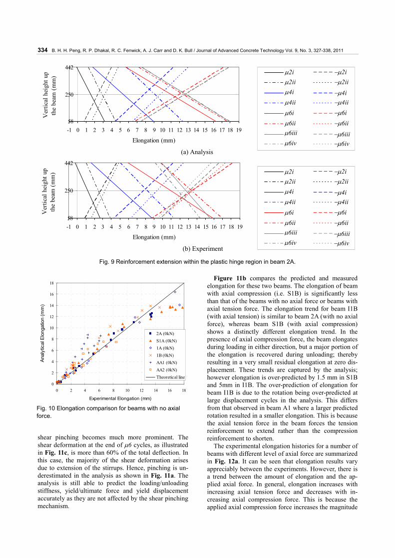
The deformation of the top and bottom longitudinal reinforcement within the plastic hinge region at the peak displacement ductility is plotted in Fig. 9. It can be seen that the analytical reinforcement extension compares satisfactorily with the experimental results up to the first cycle of displacement ductility 6. The analytical rotation after this displacement cycle is larger than the experi-mental rotation. It should be noted that a larger rotation in the analysis does not necessarily lead to a larger elongation. In this case, a larger predicted rotation forced the compression steel to yield back rather than the tension steel to extend. This is because the force required to extend the tension reinforcement, in the strain hardening region, is much greater than that to shorten the compression reinforcement and the concrete. Therefore, larger predicted rotation in this case reduces
elongation of the plastic hinge. Comparisons of the elongation history, force-
displacement and moment-rotation relationships for the other five beams tested with no axial force led to similar observations. The analytical and experimental elonga-tions for all six beams are summarized in Fig. 10. In this figure with a perfect match, the points would all lie on top of the solid line. In general, the analytical elongation for ductile beams matches satisfactorily with the ex-perimental results till near the end of the test where elongation is slightly under-predicted in the analysis except for a nominally ductile beam AA1 (Walker, 2007). This is due to the rotation being over-predicted in the analysis; thereby forcing the compression rein-forcement to yield back, which consequently retards the elongation.
4.2 Beams with different level of axial forces To cover the effect of a wide range of axial force on the general behavior of plastic hinges, the analytical and experimental results from two tests are discussed in de-tail. The first one, beam S1B (Issa 1997), was subjected to an axial compression force of 500 kN (equal to 0.14Agf’c), and the second, beam I1B (Issa 1997), was subjected to an axial tension force of 125 kN. Compari-sons between experimental and analytical results for these two beams are presented in Fig. 11.
It can be seen from the shear force versus shear dis-placement relationship in Fig. 11c that the pinching be-havior reduces dramatically in beam S1B where there is moderate axial compression force. In this case, the measured shear deformation contributes approximately 15% of the total deflection at the end of μ6 cycles. Most of the shear deformation arises due to elongation of plastic hinges, which is captured by the analysis. There-fore the predicted force-displacement relationship matches well with the experiment. On the other hand, in beam I1B where an axial tension force was applied, the
-200
-150
-100
-50
0
50
100
150
200
-30 -20 -10 0 10 20 30Shear Displacement (mm)
Shea
r For
ce (k
N)
Analysis Experiment
-300
-200
-100
0
100
200
300
-0.04 -0.03 -0.02 -0.01 0 0.01 0.02 0.03 0.04Rotation (rads)
Mom
ent (
kNm
)
Analysis Experiment
(a) Shear force-shear displacement response (b) Moment-rotation response
Fig. 8 Shear and flexural behaviors of beam 2A.
334 B. H. H. Peng, R. P. Dhakal, R. C. Fenwick, A. J. Carr and D. K. Bull / Journal of Advanced Concrete Technology Vol. 9, No. 3, 327-338, 2011
shear pinching becomes much more prominent. The shear deformation at the end of μ6 cycles, as illustrated in Fig. 11c, is more than 60% of the total deflection. In this case, the majority of the shear deformation arises due to extension of the stirrups. Hence, pinching is un-derestimated in the analysis as shown in Fig. 11a. The analysis is still able to predict the loading/unloading stiffness, yield/ultimate force and yield displacement accurately as they are not affected by the shear pinching mechanism.
Figure 11b compares the predicted and measured elongation for these two beams. The elongation of beam with axial compression (i.e. S1B) is significantly less than that of the beams with no axial force or beams with axial tension force. The elongation trend for beam I1B (with axial tension) is similar to beam 2A (with no axial force), whereas beam S1B (with axial compression) shows a distinctly different elongation trend. In the presence of axial compression force, the beam elongates during loading in either direction, but a major portion of the elongation is recovered during unloading; thereby resulting in a very small residual elongation at zero dis-placement. These trends are captured by the analysis; however elongation is over-predicted by 1.5 mm in S1B and 5mm in I1B. The over-prediction of elongation for beam I1B is due to the rotation being over-predicted at large displacement cycles in the analysis. This differs from that observed in beam A1 where a larger predicted rotation resulted in a smaller elongation. This is because the axial tension force in the beam forces the tension reinforcement to extend rather than the compression reinforcement to shorten.
The experimental elongation histories for a number of beams with different level of axial force are summarized in Fig. 12a. It can be seen that elongation results vary appreciably between the experiments. However, there is a trend between the amount of elongation and the ap-plied axial force. In general, elongation increases with increasing axial tension force and decreases with in-creasing axial compression force. This is because the applied axial compression force increases the magnitude
D2i -D2iD2ii -D2iiD4i -D4iD4ii -D4iiD6i -D6iD6ii -D6iiD6iii -D6iiiD6iv -D6iv
D2i -D2iD2ii -D2iiD4i -D4iD4ii -D4iiD6i -D6iD6ii -D6iiD6iii -D6iiiD6iv -D6iv
μ2i −μ2iμ2ii −μ2iiμ4i −μ4iμ4ii −μ4iiμ6i −μ6iμ6ii −μ6iiμ6iii −μ6iiiμ6iv −μ6iv
μ2i −μ2iμ2ii −μ2iiμ4i −μ4iμ4ii −μ4iiμ6i −μ6iμ6ii −μ6iiμ6iii −μ6iiiμ6iv −μ6iv
58
250
442
-1 0 1 2 3 4 5 6 7 8 9 10 11 12 13 14 15 16 17 18 19
Elongation (mm)
Ver
tical
hei
ght u
pth
e be
am (m
m)
(a) Analysis
58
250
442
-1 0 1 2 3 4 5 6 7 8 9 10 11 12 13 14 15 16 17 18 19
Elongation (mm)
Ver
tical
hei
ght u
pth
e be
am (m
m)
(b) Experiment
Fig. 9 Reinforcement extension within the plastic hinge region in beam 2A.
0
2
4
6
8
10
12
14
16
18
0 2 4 6 8 10 12 14 16 18
Experimental Elongation (mm)
Anal
ytic
al E
long
atio
n (m
m)
2A (0kN)S1A (0kN)1A (0kN)1B (0kN)AA1 (0kN)AA2 (0kN)Theoretical line
Fig. 10 Elongation comparison for beams with no axial force.

B. H. H. Peng, R. P. Dhakal, R. C. Fenwick, A. J. Carr and D. K. Bull / Journal of Advanced Concrete Technology Vol. 9, No. 3, 327-338, 2011 335
of the flexural compression force relative to the flexural tension force in the reinforcement. Hence the compres-sion reinforcement has to yield back further and the extension of tensile reinforcement is restrained during
load reversals. This consequently reduces the overall beam elongation.
The analytical and experimental elongation compari-son for beams with different level of axial force is illus-
0
1
2
3
4
5
6
7
-60 -40 -20 0 20 40 60
Applied Displacement (mm)
Elon
gatio
n (m
m)
-250-200
-150-100
-50
050
100150
200250
-60 -40 -20 0 20 40 60
Applied Displacement (mm)
Shea
r For
ce (k
N)
(c) Force-shear displacement response
-200
-150
-100
-50
0
50
100
150
200
-80 -60 -40 -20 0 20 40 60 80
Applied Displacement (mm)
Shea
r For
ce (k
N)
0
5
10
15
20
25
30
-80 -40 0 40 80
Applied Displacement (mm)
Elon
gatio
n (m
m)
-200
-150
-100
-50
0
50
100
150
200
-60 -40 -20 0 20 40 60
Shear Displacement (mm)
Shea
r For
ce (k
N)
-250-200-150
-100-50
050
100150
200250
-10 -5 0 5 10
Shear Displacement (mm)
Shea
r For
ce (k
N)
5 0 0
Analysis Experiment5 0 0
Analysis Experiment
5 0 0
Analysis Experiment5 0 0
Analysis Experiment
5 0 0
Analysis Experiment5 0 0
Analysis Experiment
Fig. 11 Comparison between analytical and experimental results for beams S1B and I1B
Beam S1B with Axial Compression Force Beam I1B with Axial Tension Force
(b) Elongation history
(a) Force-displacement response

336 B. H. H. Peng, R. P. Dhakal, R. C. Fenwick, A. J. Carr and D. K. Bull / Journal of Advanced Concrete Technology Vol. 9, No. 3, 327-338, 2011
trated in Fig. 12b. The figure shows that the analytical elongation matched reasonably well with the experi-mental results with the exception of beam M2. The elongation measured in beam M2, which sustained an axial tension force, is smaller than the average elonga-tion measured for beams with no axial force, which de-fies the general trend. Hence, it is suspected that there may be some errors with the experimental measure-ments in this test.
5. Discussions
Comparisons of the analytical and experimental results have indicated that the proposed plastic hinge element enables elongation of plastic hinges in ductile RC mem-bers to be taken into account in FEA. This element is also found to be capable of predicting important aspects of hysteresis response such as yield and peak forces, yield displacement, initial and unloading/reloading stiff-ness for beams sustaining different levels of axial force. The force-displacement response predicted in the analy-sis using the plastic hinge element is a natural outcome of the generic concrete and reinforcing bar models, which do not require any calibration. This is an added advantage to the current approach where the beam/frame elements in the nonlinear models are re-quired to be calibrated to yield the desired hysteresis response.
To take advantage of these added capabilities of the newly-developed plastic hinge element, a new approach for frame analysis using this element is proposed. In the proposed analytical approach, frames are modeled using a combination of elastic elements and the newly-developed plastic hinge elements in potential plastic hinge regions as shown in Fig. 13. As mentioned earlier, the plastic hinge elements are analyzed using path–
dependent stress-strain relationships of concrete and reinforcing bars, whereas the elastic elements are ana-lyzed using elastic moment-curvature relationships of the section (or force-displacement relationships of the element). This is different from the current normal prac-tice of modeling all members of a frame using frame elements, which are analyzed using nonlinear moment curvature relationships calibrated to match the desired cyclic hysteretic behavior.
Although the verifications for beams with different levels of axial force have shown promising results, the proposed plastic hinge element has room for improve-ment. As shear deformation from stirrup extension is not modeled in the analysis, the shear pinching behavior in the force-displacement response is under-estimated and the rotation is over-predicted by the analysis at large displacement cycles. This leads to larger energy dissipa-tion, which increases hysteretic damping and reduces the peak displacement in time-history analysis. Re-search is being conducted to incorporate shear deforma-tion due to stirrup extension into the plastic hinge ele-ment.
It should be noted that while shear deformation is un-der-estimated in the analysis, its effect on elongation is not dramatic. Incorporating shear deformation due to stirrup yielding, which consequently reduces the pre-dicted rotation, may only change elongation predictions slightly. Bigger rotations predicted at large displacement cycles may not directly increase elongation. In the case where no axial force is applied to the beam, a larger rotation often leads to a reduction in elongation predic-tion. Whereas when axial tension force is applied, a larger rotation will increase elongation prediction.
The length of plastic hinge element LP in the current model is calculated assuming the shear resistance of concrete in plastic hinges is negligible. This may not be
0
5
10
15
20
25
Applied Displacement Cycle
Exp
erim
enta
l Mea
sure
d E
long
atio
n (m
m) S1B (-500kN)
M1 (-200kN)
S2A (-100kN)
M2 (+75kN)
I1B (+125kN)
μ4i μ2i μ6i μ6iii 0
5
10
15
20
25
0 5 10 15 20 25
Experimental Elongation (mm)
Ana
lytic
al E
long
atio
n (m
m)
S1B (-500kN)
M1 (-200kN)
S2A (-100kN)
M2 (+75kN)
I1B (+125kN)
Theoretical line
(a) Experimental elongation summary (b) Elongation comparison
Fig. 12 Elongation for beams with different level of axial force.

B. H. H. Peng, R. P. Dhakal, R. C. Fenwick, A. J. Carr and D. K. Bull / Journal of Advanced Concrete Technology Vol. 9, No. 3, 327-338, 2011 337
the case when an appreciable axial compression force is applied to the beam. More research is required to exam-ine the shear contribution of concrete in plastic hinges with different levels of axial force. This will enable more realistic and accurate quantification of the plastic hinge length, which is an important parameter in the plastic hinge element. Moreover, the angle of the diago-nal cracks at the low moment end of plastic hinges for calculating the length of the tension shift effect is as-sumed to be constant for different levels of axial force. This may not be the case when appreciable axial com-pression/tension force is applied to the beam. More re-search is needed to quantify the length of the tension shift effect with different levels of axial force.
6. Conclusions
A plastic hinge element developed in a companion paper has been verified using cantilever beam test results available in literature. Comparisons of the analytical predictions and experimental results of ductile RC beams with different level of axial force have shown that elongation and cyclic response of the beams can be satisfactorily predicted by the proposed plastic hinge element. The relationship between the applied axial force and beam elongation was also captured by the plastic hinge element. Nevertheless, the shear response of the plastic hinge element could be improved by in-corporating shear deformation due to stirrup extension in its formulation.
Unlike the conventional analysis approach using nonlinear beam/frame elements, which require calibra-tion to yield a desired hysteresis response, the use of the proposed plastic hinge element enables cyclic behavior of RC structure to be predicted based on general mate-rial models that do not require calibration. In addition,
as current analytical approaches are unable to predict elongation and inelastic shear deformation, the proposed element offers a significant advancement in analytical prediction of RC behavior.
References American Concrete Institute, (2005). “Building code
requirements for structural concrete and commentary (ACI 318M-05).” Farmington Hills, MI.
Carr, A. J., (2004). “RUAUMOKO2D - Inelastic Dynamic Analysis.” Department of Civil Engineering, University of Canterbury, Christchurch, New Zealand.
Dhakal R. P. and Maekawa, K., (2002). “Path-dependent cyclic stress-strain relationship of reinforcing bar including buckling.” Engineering Structures, 24(11), 1383-1396.
Fenwick, R. C., Bull, D. K., MacPherson, C. and Lindsay, R., (2006). “The influence of diaphragms on strength of beams.” Proceedings of the New Zealand Society for Earthquake Engineering Conference, Napier, New Zealand.
Fenwick, R. C., Davidson, B. J. and Lau, D. B. N., (2005). “Interaction between ductile RC perimeter frames and floor slabs containing precast units.” Proceedings of the New Zealand Society for Earthquake Engineering Conference, Wairakei, New Zealand.
Fenwick, R. C., Tankut A. T. and Thom, C. W., (1981). “The deformation of reinforced concrete beams subjected to inelastic cyclic loading: experimental results.” Research Report, Department of Civil Engineering, University of Auckland, Auckland, New Zealand.
Fenwick, R. C. and Thom, C. W., (1982). “Shear deformation in reinforced concrete beams subjected to inelastic cyclic loading.” Research Report,
Proposed ApproachCurrent approach
Plastic hinge elements Elastic elements
Nonlinear frame elements
Frame to be analyzed
Fig. 13 Proposed frame analysis approach.

338 B. H. H. Peng, R. P. Dhakal, R. C. Fenwick, A. J. Carr and D. K. Bull / Journal of Advanced Concrete Technology Vol. 9, No. 3, 327-338, 2011
Department of Civil Engineering, University of Auckland, Auckland, New Zealand.
Issa, M. S., (1997). “The deformations of reinforced concrete beams containing plastic hinges in the presence of axial compression or tension load.” Master Thesis, Department of Civil Engineering, University of Auckland, Auckland, New Zealand.
Maekawa, K., Pimanmas, A. and Okamura, H., (2003). “Nonlinear Mechanics of Reinforced Concrete.” Spon Press, London, 721 pp.
Matti, N. A., (1998). “Effect of axial loads on the behaviour of reversing plastic hinges in reinforced concrete beams.” Master Thesis, Department of Civil Engineering, University of Auckland, Auckland, New Zealand.
McBride, A., Fenwick, R. C. and Davidson, B. J., (1996). “The influence of slabs on the lateral cyclic behaviour of ductile concrete frames.” Research Report, Department of Civil Engineering, University of Auckland, Auckland, New Zealand.
Peng, B. H. H., Dhakal, R. P., Fenwick, R. C., Carr, A. J. and Bull, D. K., (2011). “Elongation of plastic hinges in ductile RC members: model development.”
Journal of Advanced Concrete Technology, 9(3), 315-326.
Standards New Zealand., (2006). Concrete Structures Standard: NZS 3101:2006. Wellington, New Zealand.
To, N. H. T., Ingham, J. M. and Sritharan, S., (2001). “Monotonic non-linear analysis of reinforced concrete knee joints using strut-and-tie computer models.” Bulletin of the New Zealand Society for Earthquake Engineering, 34(3), 169-190.
Walker, A., (2007). “Assessment of material strain limits for defining different forms of plastic hinge region in concrete structures.” Master Thesis, Department of Civil Engineering, University of Canterbury, Christchurch, New Zealand.
Walker, A. F. and Dhakal, R. P., (2009). “Assessment of material strain limits for defining plastic regions in concrete structures.” Bulletin of the New Zealand Society of Earthquake Engineering, 42(2), 86-95.
Wuu, P. J. Y., (1996). “Deformations in plastic hinge zone of RC beam in ductile frame structures subjected to inelastic cyclic loading.” Master Thesis, Department of Civil Engineering, University of Auckland, Auckland, New Zealand.